


Cissell MANCONS, Suzie II, Mr. Cissell, Ms. Cissell, Sensi-Form User Manual

Form
Finishers
Models:
Suzie II
Mr. Cissell
Ms. Cissell
Sensi-Form
CISSELL MANUFACTURING COMPANY
HEADQUARTERS PHONE: (502) 587-1292
831 SOUTH FIRST ST. SALES FAX: (502) 585-3625
P.O. BOX 32270 SERVICE/PARTS FAX: (502) 681-1275
LOUISVILLE, KY 40232-2270
THIS MANUAL MUST BE GIVEN TO THE EQUIPMENT OWNER.
MANCONS 8/00 IH

WARRANTY
The Cissell Manufacturing Company (Cissell) warrants all new equipment (and the original parts thereof)
to be free from defects in material or workmanship for a period of one (1) year from the date of sale thereof
to an original purchaser for use, except as hereinafter provided. With respect to non-durable parts normally
requiring replacement in less than one (1) year due to normal wear and tear, including, but not limited to,
cloth goods, valve discs, hoses, and iron cords, and with respect to all new repair or replacement parts for
Cissell equipment for which the one (1) year warranty period has expired, or for all new repair or
replacement parts for equipment other than Cissell equipment, the warranty period is limited to ninety (90)
days from date of sale. The warranty period on each new replacement part furnished by Cissell in fulfillment
of the warranty on new equipment or parts shall be for the unexpired portion of the original warranty period
on the part replaced.
With respect to electric motors, coin meters and other accessories furnished with the new equipment, but
not manufactured by Cissell, the warranty is limited to that provided by the respective manufacturer.
Cissell's total liability arising out of the manufacture and sale of new equipment and parts, whether under
the warranty or caused by Cissell's negligence or otherwise, shall be limited to Cissell repairing or replacing,
at its option, any defective equipment or part returned f.o.b. Cissell's factory, transportation prepaid, within
the applicable warranty period and found by Cissell to have been defective, and in no event shall Cissell be
liable for damages of any kind, whether for any injury to persons or property or for any special or
consequential damages. The liability of Cissell does not include furnishing (or paying for) any labor such
as that required to service, remove or install; to diagnose troubles; to adjust, remove or replace defective
equipment or a part; nor does it include any responsibility for transportation expense which is involved
therein.
The warranty of Cissell is contingent upon installation and use of its equipment under normal operating
conditions. The warranty is void on equipment or parts; that have been subjected to misuse, accident, or
negligent damage; operated under loads, pressures, speeds, electrical connections, plumbing, or conditions
other than those specified by Cissell; operated or repaired with other than genuine Cissell replacement
parts; damaged by fire, flood, vandalism, or such other causes beyond the control of Cissell; altered or
repaired in any way that effects the reliability or detracts from its performance, or; which have had the
identification plate, or serial number, altered, defaced, or removed.
No defective equipment or part may be returned to Cissell for repair or replacement without prior written
authorization from Cissell. Charges for unauthorized repairs will not be accepted or paid by Cissell.
CISSELL MAKES NO OTHER EXPRESS OR IMPLIED WARRANTY, STATUTORY OR OTHERWISE,
CONCERNING THE EQUIPMENT OR PARTS INCLUDING, WITHOUT LIMITATION, A WARRANTY
OF FITNESS FOR A PARTICULAR PURPOSE, OR A WARRANTY OF MERCHANTABILITY. THE
WARRANTIES GIVEN ABOVE ARE EXPRESSLY IN LIEU OF ALL OTHER WARRANTIES, EXPRESS
OR IMPLIED. CISSELL NEITHER ASSUMES, NOR AUTHORIZES ANY PERSON TO ASSUME FOR IT,
ANY OTHER WARRANTY OR LIABILITY IN CONNECTION WITH THE MANUFACTURE, USE OR SALE
OF ITS EQUIPMENT OR PARTS.
For warranty service, contact the Distributor from whom the Cissell equipment or part was purchased. If
the Distributor cannot be reached, contact Cissell.
Page 1

TABLE OF CONTENTS
Cissell Equipment Warranty ................................................................................................. 1
Specifications and Dimensions ............................................................................................. 3
Installation Instructions......................................................................................................... 4
Operation and Safety Precautions ....................................................................................... 5
Operation-Controls........................................................................................................6
Service Chart and Maintenance ......................................................................................... 7-8
Revolving Form Adjustment.........................................................................................8
Instructions for Removing and Replacing Bag............................................................9
Instructions for Tying Lower Tie String ............................................................................ 1 0
Replacement Form Bags ........................................................................................................ 1 1
Instructions for Adjsting Height of Revolving Form...................................................12
Mr. Cissell Form Assembly Parts ...................................................................................... 13-14
Waist, Hip, and Lower Control Parts .................................................................................. 15
Base and Blower Parts ........................................................................................................... 16
Ms. Cissell and Sensi Form Parts ..................................................................................... 17-18
Suzie II Parts................................................................................................................19
Front and Rear Paddle Assembly.................................................................................20
Steam Column and Piping Parts ......................................................................................... 21
Condenser and Spray Gun Parts ...................................................................................... 22-23
Damper Assembly Parts......................................................................................................... 2 4
Control Panel and Electrical Parts...................................................................................... 2 5
Wiring Diagrams.................................................................................................................. 26-28
Page 2
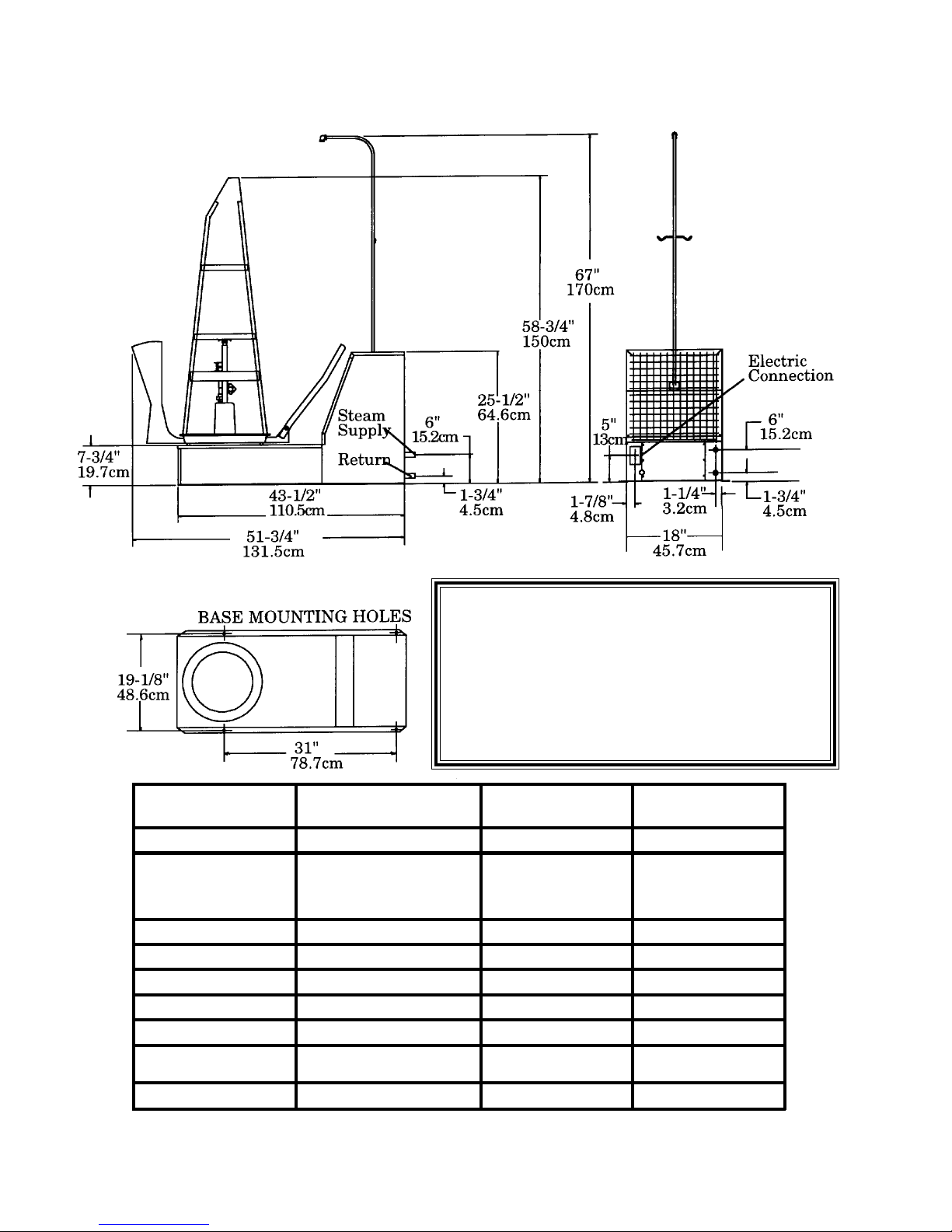
OVERALL DIMENSIONS
NOTE:
Shown with Mr. Cissell Form. To figure the height from
floor, add 7-3/4 (19.7cm) to the form heights listed
below.
Mr. Cissell - 51 (130cm)
Ms. Cissell - 58-7/8 (150cm)
Sensi-Form - 58-7/8 (150cm)
Suzie II - 59-1/4 (150.49 cm)
SPECIFICATIONS
Electrical
Maxi m um Op er at i ng P re ss ure 100 P.S.I. (6.9 Bars) 100 P.S.I. (6.9 Bars) 100 P.S.I. (6.9 Bars)
Boiler Horsepower Required 2.5 H.P. ( 1.9 kw ) 2 H .P. (1. 5 kw) 2 H .P. (1. 5 kw)
Stea m Supp ly & R etur n Line s 1/2" (1 . 27 cm) 1/ 2" (1 . 27 cm) 1/ 2" (1 . 27 cm)
Net Weight 220 lb s . (1 00 kg ) 220 lb s . (1 00 kg ) 220 lb s . (1 00 kg )
Ship ping Weight 250 lbs . (113 kg ) 250 lbs. (113 kg) 250 lbs . (113 kg )
Export Sh ipp ing Dimens io ns
Export Crate Volu me 61 Cubic Feet (1.73 m
MS. CISSELL, SENSI- FORM
CF600
1 H. P. Moto r
115V, 50/60 Hz., 1 Ph, 12 Amps
230V, 50 /6 0 Hz . , 1 Ph , 6 Am ps
61" x 25" x 69"
(155 cm x 64 cm x 175 cm)
3
) 61 Cu bic Fe et ( 1.7 3 m 3) 61 C u bic Fe et (1. 7 3 m 3)
MR. CISSELL
CF100
1 H.P. Motor
115V, 60 Hz. , 1 Ph , 6 Am ps
230V, 60 Hz. , 1 Ph , 3 Am ps
230V, 50 Hz. , 1 Ph , 3 Am ps
61" x 25" x 69"
(155 cm x 64 cm x 175 cm)
SUZIE II
1 H. P. Moto r
115V, 6 0 Hz. , 1 Ph , 6 Amps
230V, 6 0 Hz. , 1 Ph , 3 Amps
115V, 5 0 Hz. , 1 Ph . 3 Amps
61" x 25" x 69"
(155 cm x 64 cm x 175 cm)
Page 3
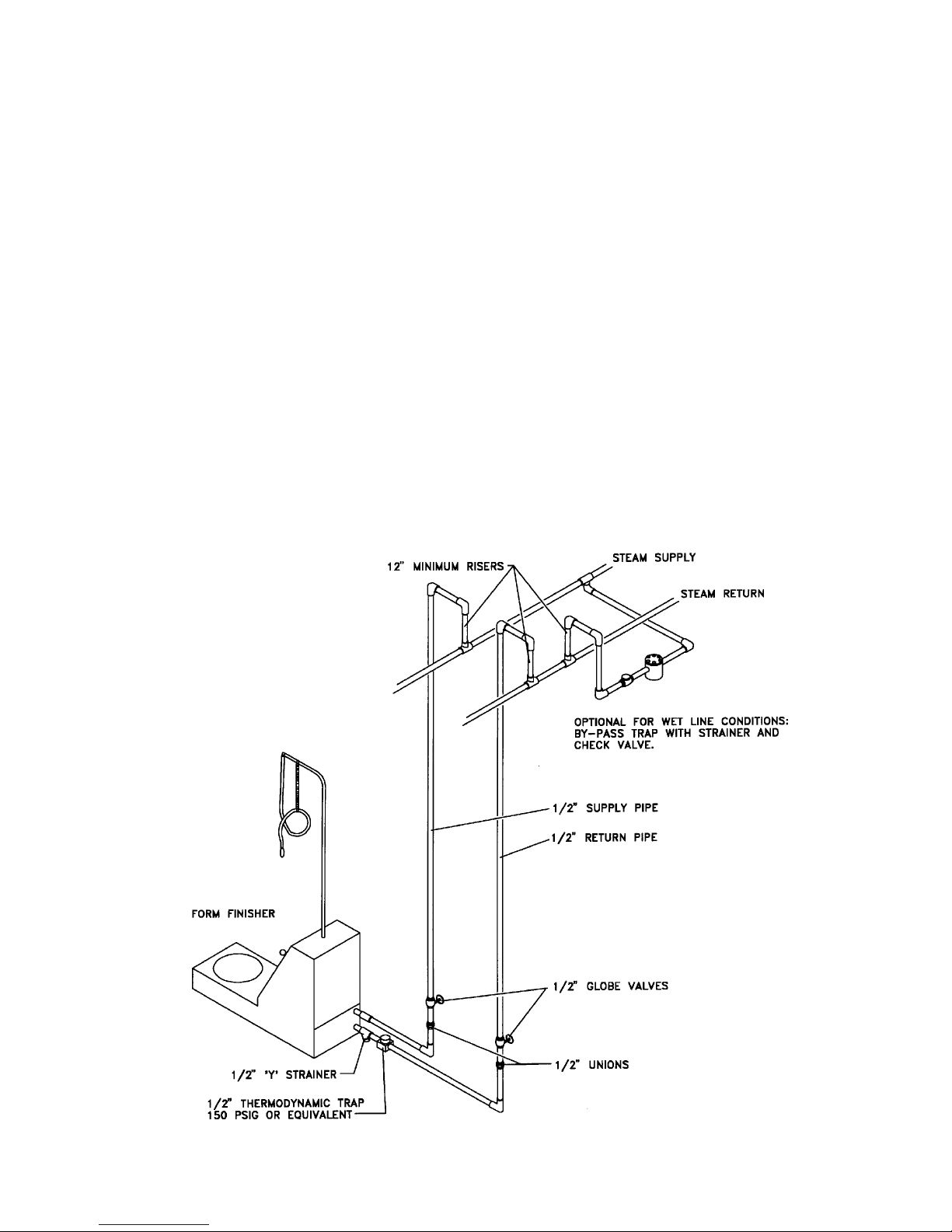
INSTALLATION INSTRUCTIONS
NOTE: This machine should be installed by qualified service personnel only.
1. Uncrate the machine. Check the nameplate voltage and current; match it with the power
being connected.
2. Set the machine in position and bolt to floor.
3. Connect Water Spray Gun to machine. Remove the Lint Screen to access the connection.
Open the valve on the Condenser and replace the Lint Screen.
4. Connect steam supply line as shown in illustration.
5. Connect steam return line as shown. NOTE: Before final return line connection is made,
open the steam supply valve and blow all foreign matter out of the steam lines. Failure to
do so will cause trap to leak.
6. Make electrical connections in junction box on rear of machine, following applicable electric
codes. Include a fused disconnect switch or circuit breaker with slow-blow characteristics
and be capable of carrying 15 amps, 115 volts or 8 amps, 230 volts.
7. Install the revolving form on the machine.
8. Turn on the electric power to machine. Remove the plastic cover from the bag. Open the
steam lines.
9. Test the machine, following the OPERATING INSTRUCTIONS in this manual.
Page 4
SAFETY PRECAUTIONS
Please read these warnings before operating or servicing machine.
CAUTION: This machine emits hot steam. To prevent burns, avoid contact with hot steam. Before
service machine, close steam supply valve and purge lines.
CAUTION: Shut off electrical supply before servicing to avoid electrical shock.
OPERATING INSTRUCTIONS
1. Machine can be operated from any side. Position foot switches at convenient location.
2. Place garment on form. Adjust shoulder form width by turning knob in either direction. The Mr.
Cissell form requires adjustment of the Waist, Hip and Lower control knobs. After adjusting lock
the controls by twisting the knobs clockwise.
3. Press the AIR foot switch to operate the blower for sizing the form bag. Size the bag by adjusting
the DAMPER CONTROL. Using the Control Panel, press the MODE SELECT until the AIR light
glows and press START/CANCEL to operate the blower, then proceed with sizing the bag.
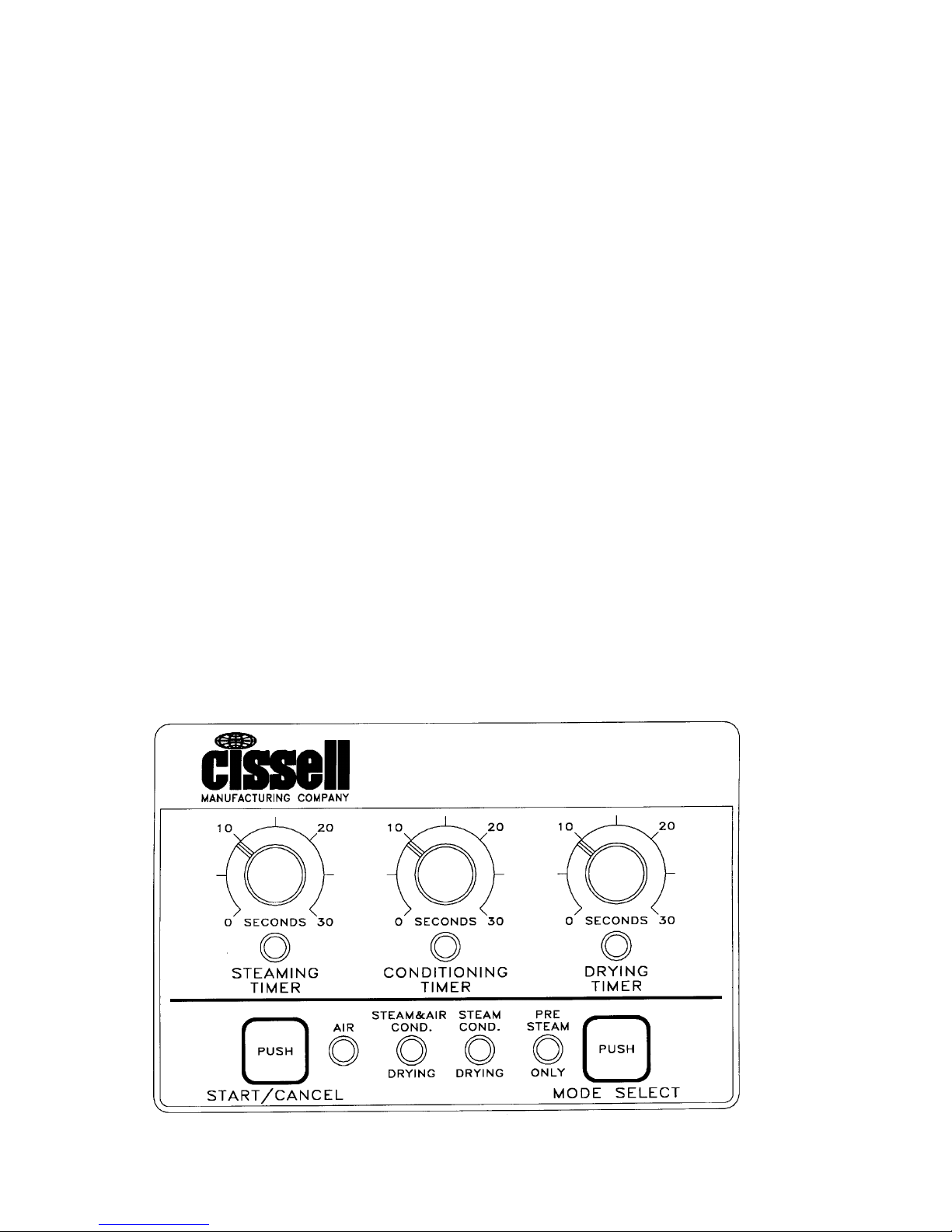
4. Set the three control timers to the recommended settings:
Steaming: 6-9 seconds
Conditioning: 4-9 seconds
Drying: 12-16 seconds
These settings should be fine-tuned to the particular garment, steam pressure and ambient
conditions. The recommended cycle is the steam/air conditioning and the drying. The control will
power up in this cycle.
5. This machine has the ability to pre-steam a garment prior to the automatic finishing cycle. To
actuate this cycle, press the MODE SELECT pad until the PRE-STEAM LIGHT glows, then press
START. Using the foot switch, press PRE-STEAM.
6. If a cycle is operating, it can be cancelled at any time by pressing any foot switch or control panel
pads.
Control Panel
Page 5
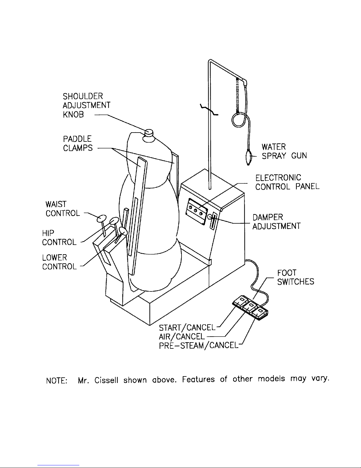
OPERATION - CONTROLS
Page 6

SERVICE CHART
CAUTION: BEFORE SERVICEING MACHINE, SHUT OFF ELECTRICAL POWER TO
AVOID POSSIBLE ELECTRICAL SHOCK. SHUT OFF STEAM SUPPLY AND PURGE
PRESSURE FROM STEAM LINES TO AVOID BURNS FROM HOT STEAM.
REFER TO PARTS SHEETS FOR CORRECT REPLACEMENT PARTS.
PROBLEM
(1) No Steam
(2) No Air
(3) Steam Valve Leaks
(4) Wet Steam
CAUSE
A. Steam supply valve closed.
B. Electric power off.
C. Bad solenoid valve coil.
D. Steam timer may slip on shaft
and be set on 0.
See item 11.
A. Damper closed.
B. Drying timer slipping.
C. Defective motor relay.
D. Blower wheel stuck.
E. Defective motor.
F. Defective motor capacitor.
See items 1B and 11.
A. Defective steam valve.
A. Trap not operating.
B. Check valve problem.
C. Strainer clogged.
D. Return line closed.
E. Steam cycle set too long.
F. Steam lines installed wrong.
G. Heavy condesate in supply.
H. Units not trapped correctly.
I. Back pressure in return line.
Page 7
REMEDY
Open valve in steam supply line.
Check for blown fuse, tripped
circuit breaker or loose wire
connection. Tighten wire nuts and
restore power.
Disconnect power and measure coil
resistance. A good coil should be
between 50-125 hms. Replace coil if
not within these parameters.
Loosen set screw and remove knob
shaft. Turn shaft to maximum
counter-clockwise position. Attach
knob to shaft pointing to 0 and
tighten set screw.
Open damper.
See item 1D.
Disconnect and measure resistance
of relay coil. A good coil should be
between 240-360 ohms. Replace
coil if not within these parameters.
Check wheel by moving by hand. If
wheel rubs or is stuck, loosen the
set screws and align the wheel on
the shaft. Tighten set screws.
Measure the resistance of the black
and white wires on the motor
terminal board. They should be
between 5-20 ohms. Replace motor
if not within these parameters.
If relay, blower wheel, and motor
are good, replace motor.
Replace valve.
Check size and operation of trap.
Refer to the Installation Instructions and make corrections in
installation if needed. Replace trap
if defective.
Check for proper installation.
Replace if bad.
Clean or replace as needed.
Open return line.
Reduce steam timer setting.
Refer to steam line Installation
Instructions.
Install by-pass from supply header
to return line.
Each machine needs separate trap.
Check trap installation. Return
lines must be gravity fed to condensate tank. Properly vent the
condensate tank.

SERVICE CHART
PROBLEM
(5) Water inthe base.
(6) Noisy or vibration.
(7) Not enough steam.
(8) Too much steam.
(9) Too much air.
(10)Form will not inflate.
(11)Timer control does not
function.
CAUSE
A. Wet steam.
B. Steam leak in machine.
See items 3, 4, and 8.
A. Foreign object in blower.
B. Wheel out of balance.
C. Wheel loose on shaft.
D. Motor mount bent.
E. Motor bearings bad..
See items 1A, 1D, or 11.
Timer set too long.
See item 11.
Timer set too long.
See item 11.
A. Damper is closed.
See items 2 and 11.
A. No power on control.
B. Moisture accumulated.
C. Timer control bad.
REMEDY
See item 4.
Inspect and repair or replace
leaking part.
Remove foreign object.
Inspect wheel for loose weights, out
of round or damage. Repair or
replace as needed.
Tighten set screws on wheel hub.
Repair or replace as needed.
Repair or replace as needed.
Reset timer.
Reset timer.
Open damper; check damper
control linkage and reapir or
replace as needed.
Check fuse on back of control,
replace if needed.
Check for steam or water leaks.
Dry out control.
Replace timer control.
REVOLVING FORM ADJUSTMENT
If the Revolving Form drags on the base rather than turning freely, it must be raised. First remove
the form by lifting it straight up off the base. Then loosen the Bearing Locknut and turn the Bearing
Adjustment Screw counter-clockwise. Check adjustment by replacing form and rotate. Repeat
adjustment if needed.
If Revolving Form is too high above base, steam will escape from between the base and the bottom of
the form. To correct, first remove form from the base. Then loosen the Bearing Locknut and turn the
Bearing Adjustment Screw clockwise. Replace form on the base and check adjustment. Repeat if
needed.
MAINTENANCE RECOMMENDATION
Change the air filter located on the rear of the machine at least every six months depending on the use
and environmental conditions. See the parts section of this manual for the replacement part number.
Page 8