

Cissell SFBMAN99, A Owner's Manual

Steam
Finishing
Board
Model A
OWNERS MANUAL
CISSELL MANUFACTURING COMPANY
HEADQUARTERS PHONE: (502) 587-1292
831 SOUTH FIRST ST. SALES FAX: (502) 585-3625
P.O. BOX 32270 SERVICE/PARTS FAX: (502) 681-1275
LOUISVILLE, KY 40232-2270
THIS MANUAL MUST BE GIVEN TO THE EQUIPMENT OWNER.
MAN99 3/98
Page 1

WARRANTY
The Cissell Manufacturing Company (Cissell) warrants all new equipment (and the original parts thereof)
to be free from defects in material or workmanship for a period of one (1) year from the date of sale thereof
to an original purchaser for use, except as hereinafter provided. With respect to non-durable parts normally
requiring replacement in less than one (1) year due to normal wear and tear, including, but not limited to,
cloth goods, valve discs, hoses, and iron cords, and with respect to all new repair or replacement parts for
Cissell equipment for which the one (1) year warranty period has expired, or for all new repair or
replacement parts for equipment other than Cissell equipment, the warranty period is limited to ninety (90)
days from date of sale. The warranty period on each new replacement part furnished by Cissell in fulfillment
of the warranty on new equipment or parts shall be for the unexpired portion of the original warranty period
on the part replaced.
With respect to electric motors, coin meters and other accessories furnished with the new equipment, but
not manufactured by Cissell, the warranty is limited to that provided by the respective manufacturer.
Cissell's total liability arising out of the manufacture and sale of new equipment and parts, whether under
the warranty or caused by Cissell's negligence or otherwise, shall be limited to Cissell repairing or replacing,
at its option, any defective equipment or part returned f.o.b. Cissell's factory, transportation prepaid, within
the applicable warranty period and found by Cissell to have been defective, and in no event shall Cissell be
liable for damages of any kind, whether for any injury to persons or property or for any special or
consequential damages. The liability of Cissell does not include furnishing (or paying for) any labor such
as that required to service, remove or install; to diagnose troubles; to adjust, remove or replace defective
equipment or a part; nor does it include any responsibility for transportation expense which is involved
therein.
The warranty of Cissell is contingent upon installation and use of its equipment under normal operating
conditions. The warranty is void on equipment or parts; that have been subjected to misuse, accident, or
negligent damage; operated under loads, pressures, speeds, electrical connections, plumbing, or conditions
other than those specified by Cissell; operated or repaired with other than genuine Cissell replacement
parts; damaged by fire, flood, vandalism, or such other causes beyond the control of Cissell; altered or
repaired in any way that effects the reliability or detracts from its performance, or; which have had the
identification plate, or serial number, altered, defaced, or removed.
No defective equipment or part may be returned to Cissell for repair or replacement without prior written
authorization from Cissell. Charges for unauthorized repairs will not be accepted or paid by Cissell.
CISSELL MAKES NO OTHER EXPRESS OR IMPLIED WARRANTY, STATUTORY OR OTHERWISE,
CONCERNING THE EQUIPMENT OR PARTS INCLUDING, WITHOUT LIMITATION, A WARRANTY
OF FITNESS FOR A PARTICULAR PURPOSE, OR A WARRANTY OF MERCHANTABILITY. THE
WARRANTIES GIVEN ABOVE ARE EXPRESSLY IN LIEU OF ALL OTHER WARRANTIES, EXPRESS
OR IMPLIED. CISSELL NEITHER ASSUMES, NOR AUTHORIZES ANY PERSON TO ASSUME FOR IT,
ANY OTHER WARRANTY OR LIABILITY IN CONNECTION WITH THE MANUFACTURE, USE OR SALE
OF ITS EQUIPMENT OR PARTS.
For warranty service, contact the Distributor from whom the Cissell equipment or part was purchased. If
the Distributor cannot be reached, contact Cissell.
Page 2

TABLE OF CONTENTS
Warranty ...................................................................................................................................... 1
Specifications .......................................................................................................................... 3-4
Installation Instructions........................................................................................................... 5
Operating Instructions.............................................................................................................. 6
Iron & Lowboy Assembly Instructions .............................................................................. 7-8
Overall View of Parts................................................................................................................. 9
Type D Lowboy Assembly & Installation...................................................................... 10-11
Lowboy Assembly Instructions.............................................................................................. 12
PARTS LISTS
Type P ......................................................................................................................................... 13
Steam Finishing Board..................................................................................................... 14-15
Base Assembly........................................................................................................................... 16
Top Assembly............................................................................................................................. 17
Chamber & Valve Assembly...................................................................................................17
Air Vacuum Valve ..................................................................................................................... 18
Steam Vacuum Valve ...............................................................................................................1 8
Pleat Setter Rack................................................................................................................ 19-20
Two in One Sleeve Board .......................................................................................................2 1
Installation of FB-154 Cover Assembly...............................................................................2 2
Head Valves ...............................................................................................................................23
Trouble-Shooting...................................................................................................................... 24
Page 3

STEAM FINISHING BOARD - MODEL A
The Cissell Steam Finishing Board comes complete with one 12 and one 18 Pleat
Setter, Pleat Setter Rack, Cover and Padding for Board and Tray Assembly. Other
equipment, such as Irons and Lowboys, is optional and must be ordered separately.
Available for steam or central air vacuum.
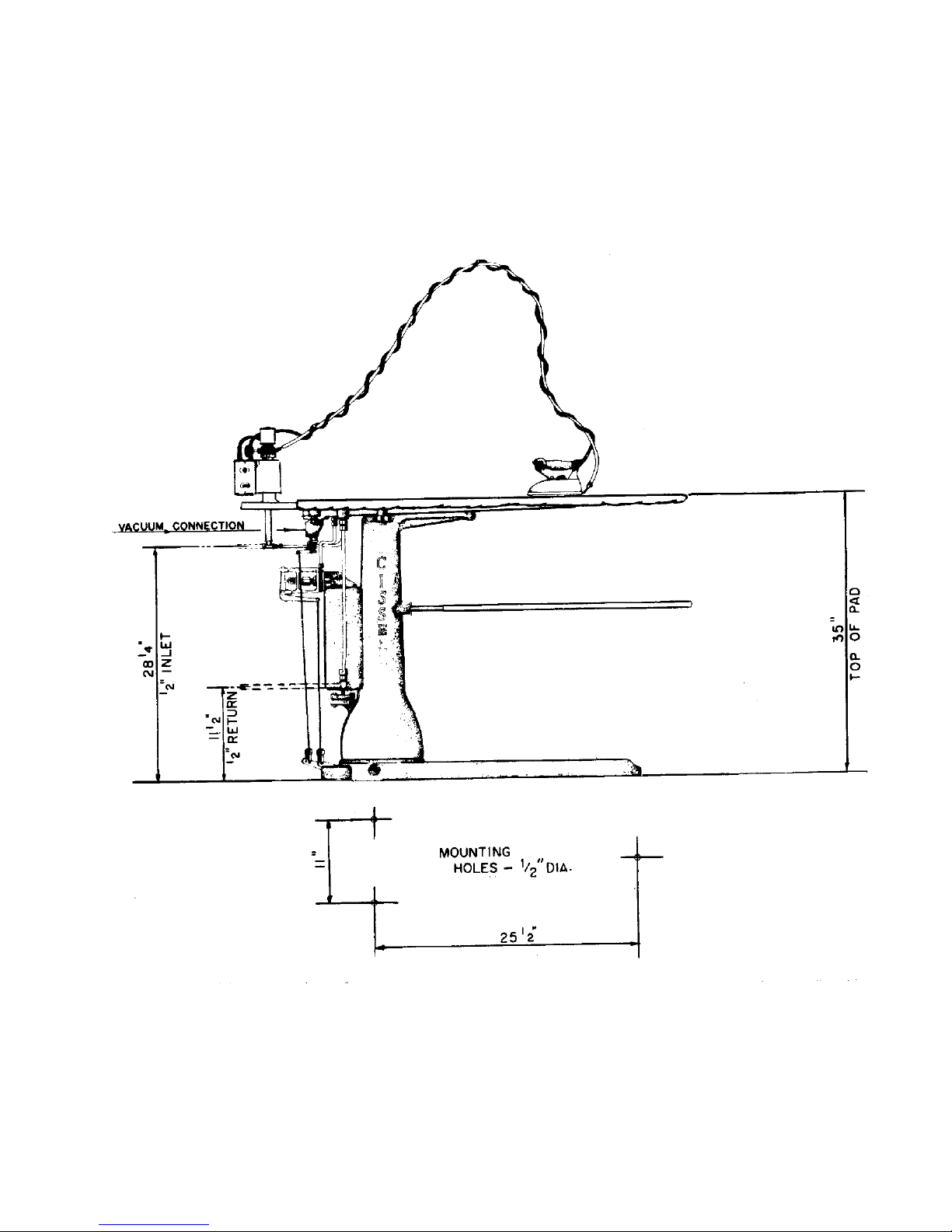
Specifications
Floor Space ............................................................................. 17 x 53 (43.2 cm x 134.6 cm)
Table Height ......................................................................................................... .37 (93.9 cm)
Length of Working Surface .............................................................................. 46 (116.4 cm)
Width of Front End or Working Surface ............................................................9 (22.9 cm)
Width of Rear End of Working Surface ........................................................... 14 (35.6 cm)
Net Weight ....................................................................................................... 260 lbs. (118 kg)
Domestic Shipping Weight ........................................................... Approx. 300 lbs. (136 kg)
Export Shipping Weight ............................................................ Approx. 475 lbs. (215.7 kg)
Export Shipping Dimensions...................... 61 x 26 x 49 (155 cm x 66 cm x 124.5 cm)
Cubic Feet Export Crating ........................................................................ 45 cu. ft. (1.26 m3)
Boiler Horsepower Required........................................................... Approx. 1 1/4 (.931 kw)
Operating Steam Pressure........................................................................... 100 P.S.I.G. Max
Steam Supply Connection ........................................................................ 1/2 Pipe (1.27 cm)
Steam Return Connection ........................................................................ 1/2 Pipe (1.27 cm)
Steam Vacuum Exhaust Connection................................................ 1 1/4 Pipe (3.175 cm)
Central Air Vacuum Connection ....................................................... 1 1/4 Pipe (3.175 cm)
Specifications with Lowboy & Steam Electric Iron
Overall Height .................................................................................................... 75 (190.5 cm)
Net Weight ....................................................................................................285 lbs. (129.4 kg)
Domestic Shipping Weight ........................................................ Approx. 330 lbs. (149.8 kg)
Export Shipping Weight ............................................................ Approx. 475 lbs. (215.7 kg)
Specifications for Two-In-One Swinging Sleeve Board Assembly (Optional)
Length of Boards .................................................................................................. 23 (58.4 cm)
One Board 6 (15.2 cm) wide at rear end, tapering to 2 1/2 (6.35 cm) at front end.
Other Board 4 7/8 (11.75 cm) wide at rear end, tapering to 2 1/2 (6.35 cm) at
front end.
Net Weight .........................................................................................Approx. 12 lbs. (5.45 kg)
Domestic Shipping Weight .............................................................Approx. 16 lbs. (7.26 kg)
Page 4
Page 5

SPECIFICATIONS
Boiler Horsepower................. Approx. 1 1/4
Operating Steam Pressure.. 60 to 100
Steam Supply ......................... 1/2 Pipe
Steam Return ......................... 1/2 Pipe
INSTALL STEAM PIPING IN ACCORDANCE WITH
ALL LOCAL REGULATIONS AND REQUIREMENTS
Installation Instructions
Make Steam Supply and
Steam Return Connections
as Illustrated
Whenever possible, horizontal
runs of steam connections must
drain by gravity to respective
Steam Holder. Portions that
drain by gravity, to machine,
without pockets.
Each Steam Holder must drain,
by gravity, to boiler or condensate return tank.
To prevent condensate draining
from Steam Holders to machine,
make steam connections to each
respective Header with a 12 Inch
(or more) vertical riser. Do not
make steam connections to a
Header with a horizontal or
downwardly facing tee or elbow.
Y STRAINER & THERMODYNAMIC TRAP
MAY BE SUBSTITUTED.
Before installing check valve and trap w/built-in strainer, open globe valve in the supply line and allow to flush out any foreign matter that may be in the casting and pipes.
This will help assure proper operation of trap when installed. If steam is gravityreturned to boiler, omit trap but install check valve in return line near machine.
NOTE: For successful operation of machine, install trap as close to floor and as near
machine as possible. Inspect trap carefully for inlet and outlet marks and install according to manufacturers instructions.
IMPORTANT: A separate steam trap should be used with each machine.
Water pockets, or an improperly
drained steam line (or header)
will provide wet steam, causing
unnecessary wetting-out of buck
padding and improper operation
of steam iron.
Page 6

OPERATING INSTRUCTIONS
1. Make certain that steam supply, steam return, and electrical connections have been
made per installation instructions.
2. Open steam supply and return valves for the finishing board. If iron lowboy has a
separate steam supply and return valves, open them also. Allow finishing board to
preheat for at least 15 minutes. (30 minutes preheating time will ensure a hot
buck).
3. Turn on the electrical switch for the iron and lowboy, so the iron can be heating
also.
4. After preheating, if the board is hooked into a central vacuum system, make
certain that it is operating. If the board is provided with steam vacuum, make
certain that it is operating.
5. Depress the iron thumb switch and observe the steam flow through the iron lowboy.
Open or close the steam valve until desired flow is achieved.
6. Place garment to be finished on the buck. Vacuum or upstream may be applied to
the entire buck surface immediately by depressing the appropriate foot pedal.
(Although both foot pedals can be depressed together, the vacuum is inoperative
when upsteaming is being performed). Iron garment using vacuum and/or up
stream as required, until desired garment finish is achieved.
7. The swinging sleeve board (if so equipped) may be used in any position over the
buck.
Page 7
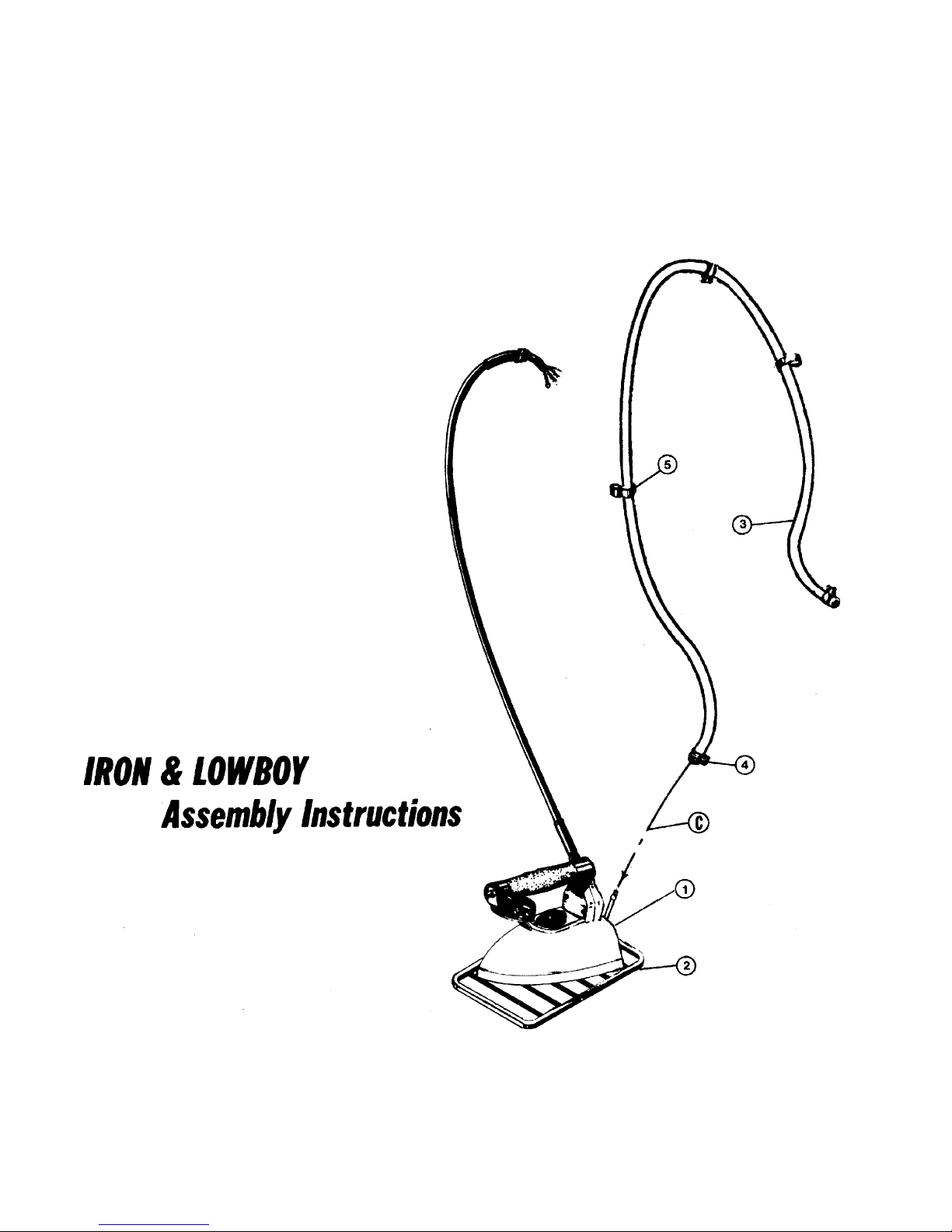
Remove iron (1), iron rest (2) and
steam hose (3) from carton.
A. Unwind iron cord which is wrapped
around iron handle.
B. Set iron on iron rest.
C. Slip steam hose (3) over iron steam
tube and tighten hose clamp (4).
D. Take steam hose (3) in one hand and
iron cord in other and wrap iron cord
around steam hose at least twelve
times. (see illustration on next page).
E. Press hose cord spring clip (5) around
iron cord to help hold cord in position.
Page 8
 Loading...