

Cissell PANTOP24VMAN594, A, B Owner's Manual

Pants
Topper
Model A
Model B
24 Volt
OWNER’S MANUAL
CISSELL MANUFACTURING COMPANY
HEADQUARTERS PHONE: (502) 587-1292
831 SOUTH FIRST ST. SALES FAX: (502) 585-3625
P.O. BOX 32270 SERVICE/PARTS FAX: (502) 681-1275
LOUISVILLE, KY 40232-2270
THIS MANUAL MUST BE GIVEN TO THE EQUIPMENT OWNER.
MAN594 05/00
Page 1

WARRANTY
The Cissell Manufacturing Company (Cissell) warrants all new equipment (and the original parts thereof)
to be free from defects in material or workmanship for a period of one (1) year from the date of sale thereof
to an original purchaser for use, except as hereinafter provided. With respect to non-durable parts normally
requiring replacement in less than one (1) year due to normal wear and tear, including, but not limited to,
cloth goods, valve discs, hoses, and iron cords, and with respect to all new repair or replacement parts for
Cissell equipment for which the one (1) year warranty period has expired, or for all new repair or
replacement parts for equipment other than Cissell equipment, the warranty period is limited to ninety (90)
days from date of sale. The warranty period on each new replacement part furnished by Cissell in fulfillment
of the warranty on new equipment or parts shall be for the unexpired portion of the original warranty period
on the part replaced.
With respect to electric motors, coin meters and other accessories furnished with the new equipment, but
not manufactured by Cissell, the warranty is limited to that provided by the respective manufacturer.
Cissell's total liability arising out of the manufacture and sale of new equipment and parts, whether under
the warranty or caused by Cissell's negligence or otherwise, shall be limited to Cissell repairing or replacing,
at its option, any defective equipment or part returned f.o.b. Cissell's factory, transportation prepaid, within
the applicable warranty period and found by Cissell to have been defective, and in no event shall Cissell be
liable for damages of any kind, whether for any injury to persons or property or for any special or
consequential damages. The liability of Cissell does not include furnishing (or paying for) any labor such
as that required to service, remove or install; to diagnose troubles; to adjust, remove or replace defective
equipment or a part; nor does it include any responsibility for transportation expense which is involved
therein.
The warranty of Cissell is contingent upon installation and use of its equipment under normal operating
conditions. The warranty is void on equipment or parts; that have been subjected to misuse, accident, or
negligent damage; operated under loads, pressures, speeds, electrical connections, plumbing, or conditions
other than those specified by Cissell; operated or repaired with other than genuine Cissell replacement
parts; damaged by fire, flood, vandalism, or such other causes beyond the control of Cissell; altered or
repaired in any way that effects the reliability or detracts from its performance, or; which have had the
identification plate, or serial number, altered, defaced, or removed.
No defective equipment or part may be returned to Cissell for repair or replacement without prior written
authorization from Cissell. Charges for unauthorized repairs will not be accepted or paid by Cissell.
CISSELL MAKES NO OTHER EXPRESS OR IMPLIED WARRANTY, STATUTORY OR OTHERWISE,
CONCERNING THE EQUIPMENT OR PARTS INCLUDING, WITHOUT LIMITATION, A WARRANTY
OF FITNESS FOR A PARTICULAR PURPOSE, OR A WARRANTY OF MERCHANTABILITY. THE
WARRANTIES GIVEN ABOVE ARE EXPRESSLY IN LIEU OF ALL OTHER WARRANTIES, EXPRESS
OR IMPLIED. CISSELL NEITHER ASSUMES, NOR AUTHORIZES ANY PERSON TO ASSUME FOR IT,
ANY OTHER WARRANTY OR LIABILITY IN CONNECTION WITH THE MANUFACTURE, USE OR SALE
OF ITS EQUIPMENT OR PARTS.
For warranty service, contact the Distributor from whom the Cissell equipment or part was purchased. If
the Distributor cannot be reached, contact Cissell.
Page 2

TABLE OF CONTENTS
———————————————————————————————————————————
Warranty .................................................................................................................................... 2
Specifications, General Information ........................................................................................... 4
Dimension Drawings .................................................................................................................. 5
Steam Connection Instructions...................................................................................................6
Steam Connections Illustration ................................................................................................... 7
Electrical Connections ................................................................................................................8
Maintenance Instructions............................................................................................................ 9
Operating Instructions .........................................................................................................10-12
Replacing Control Switches Instructions .................................................................................. 13
Air Pressure Control Operation ................................................................................................14
Installation of Bag and Boots ...................................................................................................15
Pants Topper Bag, Steam Leaks ..............................................................................................16
Pleat Setter Cover Assembly and Adjustment .......................................................................... 17
Plastic Sleeve, Bearing Adjustment .......................................................................................... 18
Motor and Blower Assembly Removal.....................................................................................19
Belt T ension Adjustment, Pulley Alignment ............................................................................. 19
Installation of Foot Switch........................................................................................................20
ILLUSTRATED PARTS
Overall View.............................................................................................................................21
Overall View.............................................................................................................................22
Motor and Blower Assembly.................................................................................................... 23
Control Switches and Air Cylinder ......................................................................................24-26
Piping and Tubing ....................................................................................................................27
Solenoid V alve Parts.................................................................................................................28
Air Line Assembly ....................................................................................................................29
Electric Control Box .................................................................................................................30
Wiring Diagram ........................................................................................................................31
Page 3
SPECIFICATIONS
Electric Motor........................................ 1/3 H.P., 115V. or 230V., 60 Cycle, AC, 1 Phase
........................................................... 220V., 50 Cycle, AC, 1 Phase
Operating Steam Pressure..................... 100 P.S.I.G. (5.8 Bars) Maximum
Boiler Horsepower (Approx.).................. 3/4 (7.3 kw)
Steam Supply Line................................. 1/2” Pipe (1.3 cm)
Steam Return Line............................................. 1/2” Pipe (1.3 cm)
*Air Supply Connection................................... 1/8” Pipe (.32 cm)
*Air Supply Requirement................................. 80 P.S.I.G., 6 C.F.M. (4.4 Bar, 2 C.M.M.)
Net Weight Model A......................................... 200 Pounds (100 kg)
Net Weight Model B.......................................... 230 Pounds (104.5 kg)
Note: Specifications are subject to change without prior notice.
GENERAL INFORMATION
*IMPORTANT: The air line filter was removed from the machine for shipping. When installing the unit, fasten the air line filter to the
regulator as shown in the “Air Line Assenbly” drawing in the Parts section of this manual.
UNCRATING: Set crate upright, remove sides and top. Remove the two rear base bolts and lift from crate.
PROTECTIVE PLASTIC COVER: Do not remove plastic cover from the nylon pants topper bag until machine is
installed and is ready for operation.
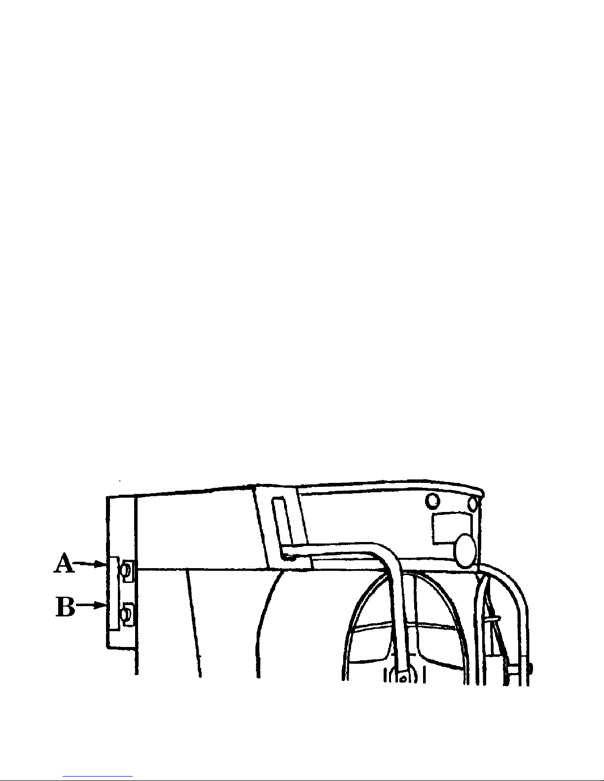
AUTOMATIC STEAM TIMER: The Automatic Steam Timer (A) is adjustable from 0 to 60 seconds, and is set at the
factory for 4 seconds normal steaming. Adjust as required.
AUTOMATIC AIR TIMER: The Automatic Air Timer (B) is adjustable for 0 to 60 seconds and is factory set for 25
seconds for normal drying. Adjust as required.
*MODEL B ONLY
Page 4
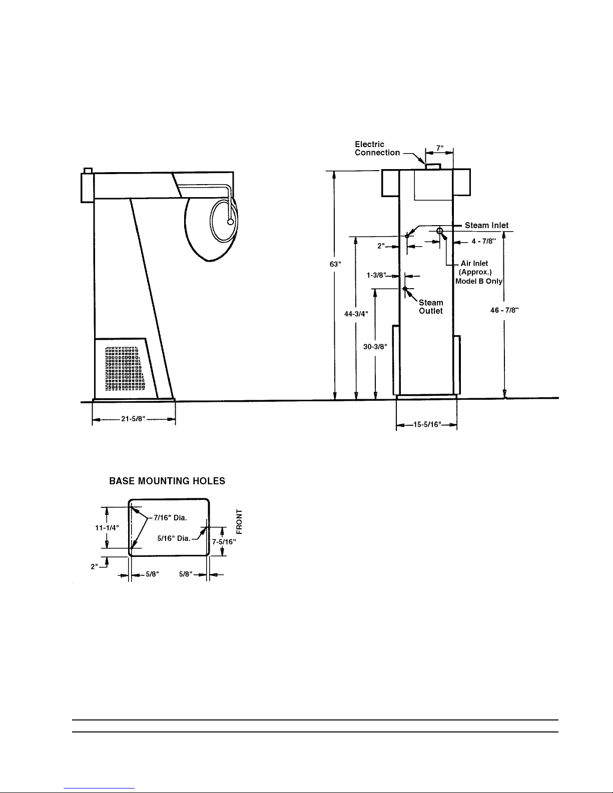
PANTS TOPPER - DIMENSION DRAWINGS
Dimensions given in inches plus/minus 1/2” and are subject to change without prior notice
Page 5

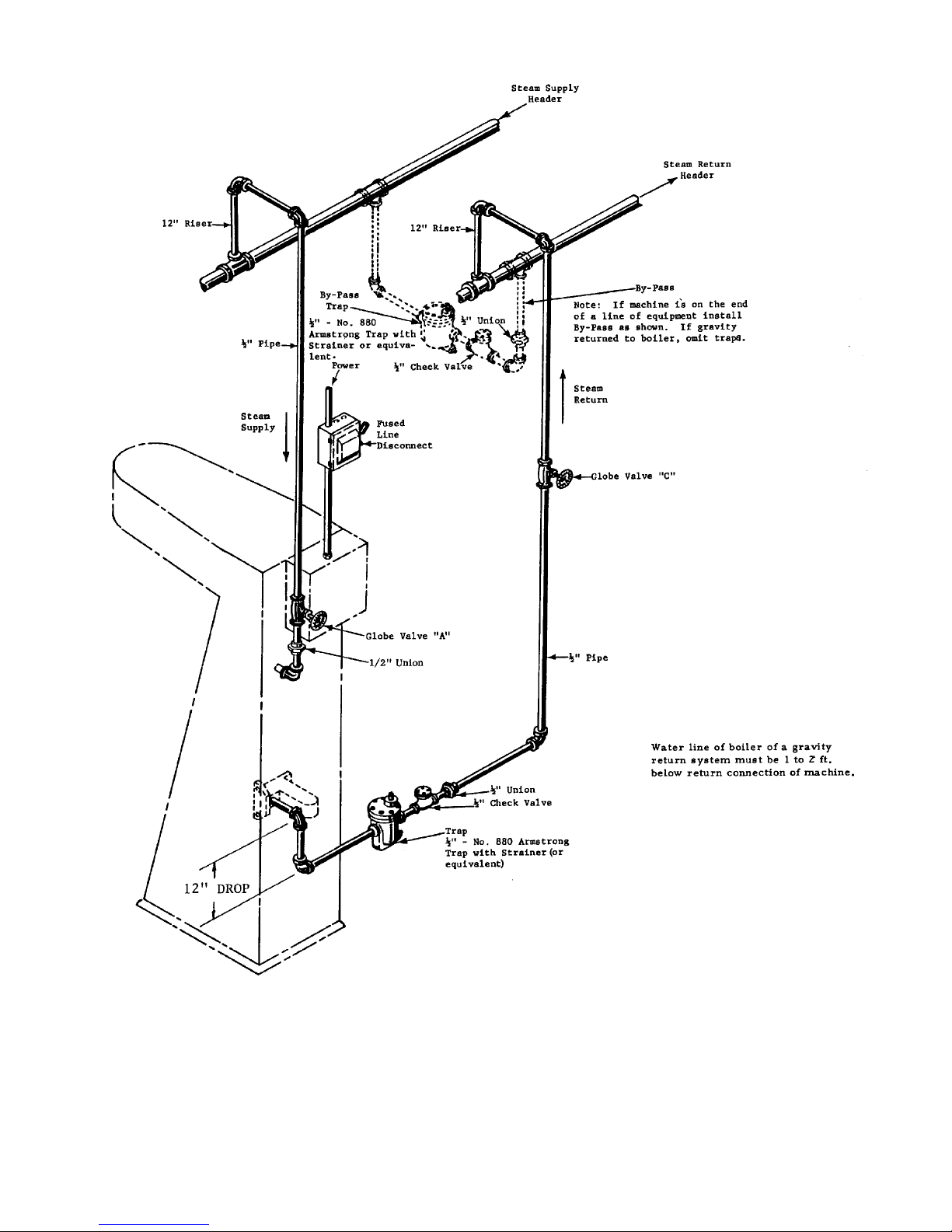
STEAM CONNECTIONS
Make Steam Supply and Steam Return connections as shown in Figure 2.
All horizontal runs must drain by gravity to respective Steam Header. Portions that connot drain
to Header must drain by gravity to machine,
Each Steam Header must drain, by gravity, to boiler or condensate return tank.
To prevent condensate draining from Steam Headers to machine, make steam connections (to
each respective Header) with a 12 inch or more
a Header with a horizontal or downwardly facing tee or elbow.
Water pockets, or an improperly drained steam line (or header), will provide wet steam, causing
unnecessary wetting-out of buck padding.
Before installing check valve, trap and strainer, connect steam supply to machine from globe
valve (A). Open globe valve (A) to flush any foreign matter that may be in castings or pipes; open
globe valve (C) to flush foreign matter from return connections, then connect steam return from
valve (C) to machine with check valve, trap, and strainer as shown. If steam is gravity returned
to boiler, omit trap.
without water pockets.
vertical riser. Do not make steam connections to
NOTE: For successful operation of machine, install trap as close to floor and as near machine as
possible. Inspect trap carefully for inlet and outlet marks and install according to manufacturer’s
instructions.
IMPORTANT: A separate steam trap must be used with each machine.
CAUTION
BEFORE OPERATING PANTS TOPPER, OPEN GLOBE VALVES IN STEAM LINES.
CHECK CAREFULLY FOR STEAM LEAKS, AND SEE THAT TRAP IS OPERATING PROPERLY. UNDER NO CIRCUMSTANCES SHOULD MACHINE BE OPERATED UNTIL HOT.
OPERATING THE MACHINE COLD WILL WET THE NYLON BAG AND PADDING.
TO DRY A WET BAG OR PAD, DEPRESS THE “ON” MANUAL AIR SWITCH. AIR WILL
OPERATE CONTINOUSLY UNTIL “OFF” AIR SWITCH IS DEPRESSED.
Page 6
Page 7

ELECTRICAL CONNECTIONS
THE STANDARD Pants Topper has single phase motors. Before installation, check nameplates
on motor and control box for rated voltage and current specifications.
MAKE ELECTRICAL CONNECTIONS as indicated on wiring diagram attached to inside cover
of electrical junction box on Topper. Voltage and current of power line must be the same as the
Electrical Specifications of the motor, timers, relays, and solenoid.
FOR SINGLE PHASE CURRENT, connect power leads, L1 and L2, to an approved fused disconnect switch in power line.
TO CONNECT STANDARD, SINGLE PHASE MACHINE TO THREE PHASE CURRENT, connect power leads, L1 and L2, to any two terminals of an approved fused disconnect switch in the
three phase power line.
FOR THREE PHASE CURRENT, connect power leads L1, L2, and L3 to the three terminals of an
approved fused disconnect switch in the three phase power line. The motor must rotate clockwise
when facing the belt and pulley. If rotation is incorrect, transpose any two leads connecting the
power line, and rotation of motor will reverse.
IMPORTANT: Consult your local electrical code before making any electrical connections; be
certain that the electrical installation conforms with all local requirements.
Always check wiring before closing the disconnect switch.
Page 8

MAINTENANCE INSTRUCTIONS
IMPORTANT - Shut-off steam and electric power before performing Maintenance
Operations. Compressed air should also be cut off.
ELECTRIC MOTOR LUBRICATION:
SLEEVE BEARINGS: Motors with wool-packed sleeve bearings are oiled at the factory for two
years normal operation. After two years normal operation, add annually 1/2 teaspoon electric
motor oil or SAE-10 to each bearing. For 24 hours per day operation, add one teaspoon of oil
annually.
BALL BEARING: Motors having ball bearings are packed with sufficient grease for approximately TEN YEARS of normal operation. After ten years of normal operation, the bearings and
housing should be cleaned thoroughly. Repack each bearing and the cavity back of the bearing 1/
3 full with G. E. Ball Bearing grease.
CHECK VOLTAGE AND CURRENT:
Your Topper is wired for a given voltage and current as stamped on name plate. Motor, Timers,
Relays and Solenoid are for Single Voltage and Single current only. If machine is to be operated
on any voltage and current, other than apecified above, THE MOTOR, RELAYS, TIMERS AND
SOLENOID MUST BE REPLACED WITH UNITS CORRESPONDING TO THE VOLTAGE
AND CURRENT ON WHICH THEY ARE TO BE OPERATED.
GENERAL CLEANING:
Every six months remove top cover, rear panel, front panel, blower and belt guards and clean
thoroughly with a vacuum cleaner or air hose.
AIR LINE OIL LUBRICATOR (MODEL B)
Check Air Line Oil Lubricator and refill when less than half full. Use #10 weight oil.
Page 9
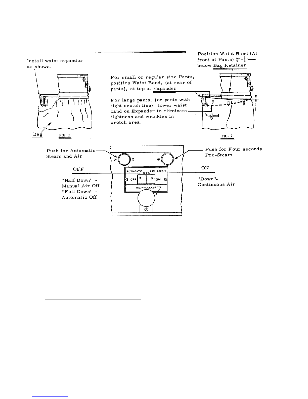
POSITIONING PANTS ON TOPPER
OPERATING INSTRUCTIONS
(A) At “Start-Up” (or after “Idle Periods” of operation) preheat before operating:
a . Lower pleat clamps onto padded buck; Operate Topper on “Manual Air”
continuously for about one (1) minute.
(B) Either PRE-STEAM or AUTOMATIC Steam-Air cycle may be cancelled by
pushing “OFF” Air Switch fully down.
(C) For Suede, Chamois or leather trimmed trousers, use manual air switch to provide
air “while steaming”, as full air pressure is required to hold pants taut during steaming
cycle.
(D) Tops Trousers, slacks, shorts (Lightweight or Heavyweight) sizes 28 to 50.
NOTE: Top small sizes, (including boys pants and small size ladies
slacks) on 1M Puff Iron.
Top large sizes on end of utility press.
Page 10
 Loading...