

Cissell PUFFIRONDMAN343, D Owner's Manual

Puff IronPuff Iron
Puff Iron
Puff IronPuff Iron
Model ‘D’Model ‘D’
Model ‘D’
Model ‘D’Model ‘D’
OWNER’S MANUALOWNER’S MANUAL
OWNER’S MANUAL
OWNER’S MANUALOWNER’S MANUAL
CISSELL MANUFACTURING COMPANYCISSELL MANUFACTURING COMPANY
CISSELL MANUFACTURING COMPANY
CISSELL MANUFACTURING COMPANYCISSELL MANUFACTURING COMPANY
HEADQUARTERSHEADQUARTERS
HEADQUARTERS PHONE: (502) 587-1292
HEADQUARTERSHEADQUARTERS
831 SOUTH FIRST ST. SALES FAX: (502) 585-3625
P.O. BOX 32270 SERVICE/PARTS FAX: (502) 681-1275
LOUISVILLE, KY 40232-2270
THIS MANUAL MUST BE GIVEN TO THE EQUIPMENT OWNER.THIS MANUAL MUST BE GIVEN TO THE EQUIPMENT OWNER.
THIS MANUAL MUST BE GIVEN TO THE EQUIPMENT OWNER.
THIS MANUAL MUST BE GIVEN TO THE EQUIPMENT OWNER.THIS MANUAL MUST BE GIVEN TO THE EQUIPMENT OWNER.
MAN 343 8/95MAN 343 8/95
MAN 343 8/95
MAN 343 8/95MAN 343 8/95
Page 1Page 1
Page 1
Page 1Page 1

WARRANTYWARRANTY
WARRANTY
WARRANTYWARRANTY
The Cissell Manufacturing Company (Cissell) warrants all new equipment (and the original parts thereof)
to be free from defects in material or workmanship for a period of one (1) year from the date of sale thereof
to an original purchaser for use, except as hereinafter provided. With respect to non-durable parts normally
requiring replacement in less than one (1) year due to normal wear and tear, including, but not limited to,
cloth goods, valve discs, hoses, and iron cords, and with respect to all new repair or replacement parts for
Cissell equipment for which the one (1) year warranty period has expired, or for all new repair or
replacement parts for equipment other than Cissell equipment, the warranty period is limited to ninety (90)
days from date of sale. The warranty period on each new replacement part furnished by Cissell in fulfillment
of the warranty on new equipment or parts shall be for the unexpired portion of the original warranty period
on the part replaced.
With respect to electric motors, coin meters and other accessories furnished with the new equipment, but
not manufactured by Cissell, the warranty is limited to that provided by the respective manufacturer.
Cissell's total liability arising out of the manufacture and sale of new equipment and parts, whether under
the warranty or caused by Cissell's negligence or otherwise, shall be limited to Cissell repairing or replacing,
at its option, any defective equipment or part returned f.o.b. Cissell's factory, transportation prepaid, within
the applicable warranty period and found by Cissell to have been defective, and in no event shall Cissell be
liable for damages of any kind, whether for any injury to persons or property or for any special or
consequential damages. The liability of Cissell does not include furnishing (or paying for) any labor such
as that required to service, remove or install; to diagnose troubles; to adjust, remove or replace defective
equipment or a part; nor does it include any responsibility for transportation expense which is involved
therein.
The warranty of Cissell is contingent upon installation and use of its equipment under normal operating
conditions. The warranty is void on equipment or parts; that have been subjected to misuse, accident, or
negligent damage; operated under loads, pressures, speeds, electrical connections, plumbing, or conditions
other than those specified by Cissell; operated or repaired with other than genuine Cissell replacement
parts; damaged by fire, flood, vandalism, or such other causes beyond the control of Cissell; altered or
repaired in any way that effects the reliability or detracts from its performance, or; which have had the
identification plate, or serial number, altered, defaced, or removed.
No defective equipment or part may be returned to Cissell for repair or replacement without prior written
authorization from Cissell. Charges for unauthorized repairs will not be accepted or paid by Cissell.
CISSELL MAKES NO OTHER EXPRESS OR IMPLIED WARRANTY, STATUTORY OR OTHERWISE,
CONCERNING THE EQUIPMENT OR PARTS INCLUDING, WITHOUT LIMITATION, A WARRANTY
OF FITNESS FOR A PARTICULAR PURPOSE, OR A WARRANTY OF MERCHANTABILITY. THE
WARRANTIES GIVEN ABOVE ARE EXPRESSLY IN LIEU OF ALL OTHER WARRANTIES, EXPRESS
OR IMPLIED. CISSELL NEITHER ASSUMES, NOR AUTHORIZES ANY PERSON TO ASSUME FOR IT,
ANY OTHER WARRANTY OR LIABILITY IN CONNECTION WITH THE MANUFACTURE, USE OR SALE
OF ITS EQUIPMENT OR PARTS.
For warranty service, contact the Distributor from whom the Cissell equipment or part was purchased. If
the Distributor cannot be reached, contact Cissell.
Page 2Page 2
Page 2
Page 2Page 2

DIMENSION DRADIMENSION DRA
DIMENSION DRA
DIMENSION DRADIMENSION DRA
All dimensions are in inches ± 1/4.
WINGSWINGS
WINGS
WINGSWINGS
Page 3Page 3
Page 3
Page 3Page 3

INSTRUCTIONS FOR STEAM CONNECTIONS FOR PUFF IRONSINSTRUCTIONS FOR STEAM CONNECTIONS FOR PUFF IRONS
INSTRUCTIONS FOR STEAM CONNECTIONS FOR PUFF IRONS
INSTRUCTIONS FOR STEAM CONNECTIONS FOR PUFF IRONSINSTRUCTIONS FOR STEAM CONNECTIONS FOR PUFF IRONS
IMPORTANT:IMPORTANT:
IMPORTANT:
IMPORTANT:IMPORTANT:
1. Set and anchor machine in position. Machine should be level to assure proper steam
circulation.
2. To prevent condensate draining from headers to machine, piping should have a
minimum riser 12” above each respective header as illustrated. Do not make steam
connection to header with a horizontal or downwardly facing tee or elbow.
3. Whenever possible, horizontal runs of steam must drain, by gravity, to respective
steam header. Water pocket or an improperly drained steam header will provide wet
steam cauing unecessary wetting-out of head covers.
4. In both the steam supply and steam return line, it is recommended that each have a
1/2” union and 1/2” globe valve. This will enable you to disconnect the steam
connections and block steam flow to and from machine while servicing machine.
5. Before installing trap and check valve in steam return line, open globe valve in steam
supply line to allow steam to flow through machine to flush out any dirt and scale from
machine. This will assure proper operation of trap when connected.
6. After flushing system, install bucket trap (with built-in stainer) and check valve as
illustrated. For sucessful operation of machine, install trap as close to floor and as near
to machine as possible. Inspect trap carefully for inlet and outlet marking and install
according to manufacturer instructions.
If steam is gravity-returned to boiler, omit trap but install check valve in return line
near machine.
7. Install union and globe valve to return line and make final pipe connection to return
header.
INSTALL STEAM PIPING IN ACCORDANCE WITHINSTALL STEAM PIPING IN ACCORDANCE WITH
INSTALL STEAM PIPING IN ACCORDANCE WITH
INSTALL STEAM PIPING IN ACCORDANCE WITHINSTALL STEAM PIPING IN ACCORDANCE WITH
ALL LOCAL REGULATIONS AND REQUIREMENTS.ALL LOCAL REGULATIONS AND REQUIREMENTS.
ALL LOCAL REGULATIONS AND REQUIREMENTS.
ALL LOCAL REGULATIONS AND REQUIREMENTS.ALL LOCAL REGULATIONS AND REQUIREMENTS.
CAUTION:CAUTION:
CAUTION: Before operating Puff Iron, open globe valves in steam lines
CAUTION:CAUTION:
and allow Puff Iron to warm up. Under no circumstances
should machine be operated until hot.
RECOMMENDATIONSRECOMMENDATIONS
RECOMMENDATIONS
RECOMMENDATIONSRECOMMENDATIONS
1. Use a separate trap for each unit. Always keep the trap clean and in good working
condition.
2. When machine is on the end of a line of equipment, extend headers at least 4 ft. beyond
machine. Install globe valve, union, check valve trap and optional by-pass at the end of
a line. If gravity return to boiler, omit trap.
3. Insulate steam supply and return line for safety of operator and safety while servicing
machine.
4. Keep machine in good working condition. Repair or replace any worn or defective parts.
Page 4Page 4
Page 4
Page 4Page 4
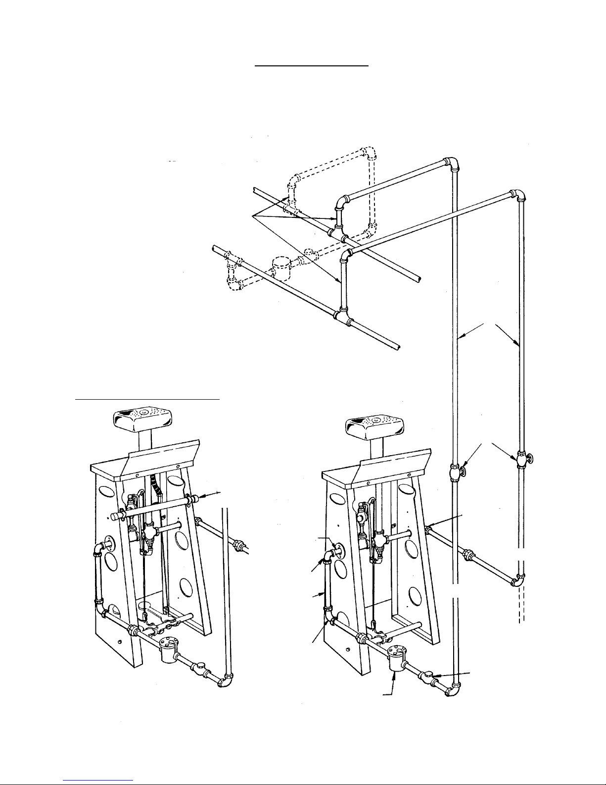
STEAM PIPINGSTEAM PIPING
STEAM PIPING
STEAM PIPINGSTEAM PIPING
For wet line conditions, trap w/strainer and
check valve should be installed (dotted lines).
12” Minimum Risers
RETURN
All piping parts beyond connection
points to be furnished by customer.
CENTRAL AIR VACUUM
1-1/4” Vacuum
Connection
3/4” Return
Connection
3/4” Elbow
12” Drop
SUPPLY
1/2” Pipes
Globe
Valves
1/2”
Supply
Connection
SUPPLY
RETURN
3/4” x 1/2”
Elbow
Bucket Trap w/Strainer
(Thermodynamic Trap and
Y-Strainer may be substituted)
Page 5Page 5
Page 5
Page 5Page 5
Check Valve
PUFF IRON PUFF IRON
PUFF IRON
PUFF IRON PUFF IRON
TT
ABLE ABLE
T
ABLE
TT
ABLE ABLE
ARRANGEMENTSARRANGEMENTS
ARRANGEMENTS
ARRANGEMENTSARRANGEMENTS
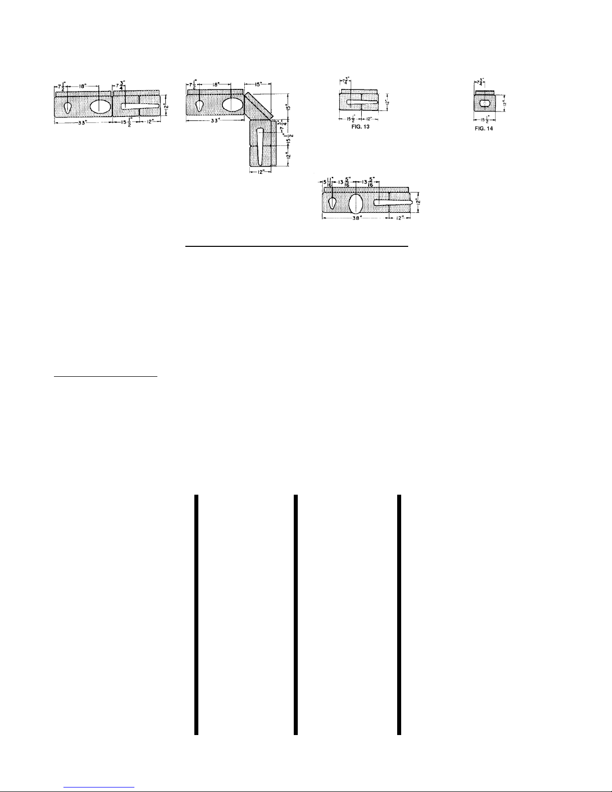
Drawings show in-line or angle arrangement of one
Double Table and one Single Table. Note use of
Angular Corner and Square Extension.
Note head centers on tables shown. Angular Corner and Back
used for angle arrangement. Square Extension with bracket
used with No. 4X, 4C or 4 Sleever for extra working space.
PUFF IRON SPECIFICAPUFF IRON SPECIFICA
PUFF IRON SPECIFICA
PUFF IRON SPECIFICAPUFF IRON SPECIFICA
SINGLE TABLESINGLE TABLE
SINGLE TABLE
SINGLE TABLESINGLE TABLE
One 15-1/2” SINGLE TABLE.One 15-1/2” SINGLE TABLE.
One 15-1/2” SINGLE TABLE.
One 15-1/2” SINGLE TABLE.One 15-1/2” SINGLE TABLE.
Unit includes No. 4C Sleever
with 12” extension.
TIONSTIONS
TIONS
TIONSTIONS
SINGLE TABLESINGLE TABLE
SINGLE TABLE
SINGLE TABLESINGLE TABLE
One 15-1/2” SINGLE TABLE.One 15-1/2” SINGLE TABLE.
One 15-1/2” SINGLE TABLE.
One 15-1/2” SINGLE TABLE.One 15-1/2” SINGLE TABLE.
Unit includes No. 1M Men’s
Shoulder.
Drawing shows suggested
heads on 38” Triple Table.
Steam Pressure ......................................................................................... 60-100 P.S.I.G.
(4.14 - 6.9 Bars)
Steam Supply................................................................................... 1/2” Pipe Connection
Steam Return................................................................................... 3/4” Pipe Connection
Vacuum Connection.............................................................................. 1-1/4” Connection
Vacuum Requirement.........................................................................1/4” Press Capacity
Boiler Horsepower
Single Puff Iron Table .......................................................................... 1/8 H.P.
Double Puff Iron Table......................................................................... 1/4 H.P.
Triple Puff Iron Table........................................................................... 3/8 H.P.
APPROXIMAAPPROXIMA
APPROXIMA
APPROXIMAAPPROXIMA
UNITUNIT
UNIT
UNITUNIT
(with fabric pressing heads)(with fabric pressing heads)
(with fabric pressing heads)
(with fabric pressing heads)(with fabric pressing heads)
33” Double Table with 2 and
4-C with extension and bracket.
33” Double Table with 1-L, 2;
15-1/2” Single Table with 4-C
with extension and bracket.
15-1/2” Single Table with 1-M
Shoulder
(without fabric pressing heads)(without fabric pressing heads)
(without fabric pressing heads)
(without fabric pressing heads)(without fabric pressing heads)
33” Double Table with 2 and
4-C with extension and bracket.
38” Triple Table with 1-L, 2
4-C with extension and bracket.
15-1/2” Single Table with 1-M
Shoulder
TE SHIPPING TE SHIPPING
TE SHIPPING
TE SHIPPING TE SHIPPING
DOMESTICDOMESTIC
DOMESTIC
DOMESTICDOMESTIC
215 lbs. (97.5 kg.)
175 lbs. (79.4 kg.)
62 lbs. (28.1 kg)
195 lbs. (88.5 kg.)
125 lbs. (56.7 kg.)
57 lbs. (25.9 kg.)
WEIGHTSWEIGHTS
WEIGHTS
WEIGHTSWEIGHTS
EXPORTEXPORT
EXPORT
EXPORTEXPORT
465 lbs. (210.9 kg.)
415 lbs. (188.2 kg.)
105 lbs. (47.6 kg)
445 lbs. (201.9 kg.)
275 lbs. (124.7 kg.)
100 lbs. (45.7 kg.)
EXPORT SHIPPINGEXPORT SHIPPING
EXPORT SHIPPING
EXPORT SHIPPINGEXPORT SHIPPING
DIMENSIONSDIMENSIONS
DIMENSIONS
DIMENSIONSDIMENSIONS
74” x 23” x 53” (188 cm x 58 cm x
135 cm) 52.2 cu. ft. (1.48 m³)
66” x 23” x 51” (168 cm x 58 cm x
130 cm) 44.8 cu. ft. (1.27 m³)
18” x 15” x 53” (46 cm x 38 x
135 cm) 8.3 cu. ft. (0.24 m³)
74” x 18” x 50” (188 cm x 46 cm x
127 cm) 38.5 cu. ft. (1.09 m³)
41” x 29” x 47” (104 cm x 74 cm x
119 cm) 32.2 cu. ft. (0.91 m³)
20” x 15” x 50” (51 cm x 38 cm x
127 cm) 8.7 cu. ft. (0.25 m³)
Page 6Page 6
Page 6
Page 6Page 6
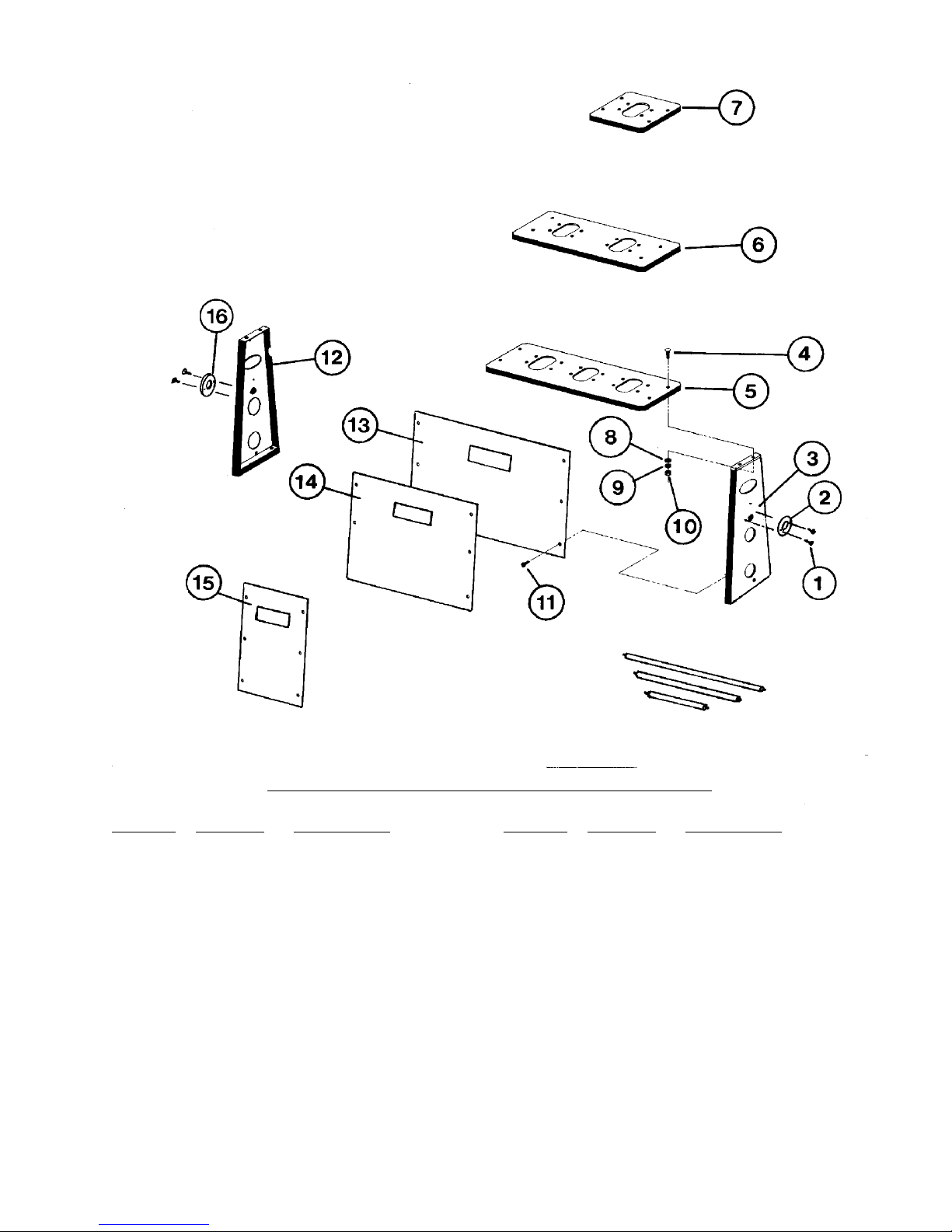
Support Bars
See Separate Page
PUFF IRON PUFF IRON
PUFF IRON
PUFF IRON PUFF IRON
Ref. No.Ref. No.
Ref. No.
Ref. No.Ref. No.
1 TU7733 #8 x 1/2” Self Drill Screw
2 F225 Spacer Ring (Return)
3 P454 Right Table Leg
4 P219 Truss Hd. Bolt, 1/4 -
5 P165 Triple Top - 38”
6 P153 Double Top - 33”
7 P154 Single Top - 15-1/2”
8 TU2847 Cut Washer, 1/4”
Part No.Part No.
Part No.
Part No.Part No.
DescriptionDescription
Description
DescriptionDescription
(Pkg. of 6)
20 x 1/2”
* Consists of Front Panel, Cissell Namplate, screws and washers.
NOTE: For service, new design allows easy access from front of machine
“D”“D”
MODEL MODEL
“D”
MODEL
“D”“D”
MODEL MODEL
by removing front panel screws and washers. Nuts are welded to
table legs.
Page 7Page 7
Page 7
Page 7Page 7
TT
ABLE PABLE P
T
ABLE P
TT
ABLE PABLE P
Ref. No.Ref. No.
Ref. No.
Ref. No.Ref. No.
9 TU2846 Lockwasher, 1/4”
10 TU4934 Hex Nut, 1/4” - 20
11 P509 Phillips Screw, 1/4” -
12 P455 Left Table Leg
13 P513 Triple Front Panel Asm.*
14 P512 Double Front Panel Asm.*
15 P511 Single Front Panel Asm.*
16 P528 Spacer Ring (Supply)
Part No.Part No.
Part No.
Part No.Part No.
ARTSARTS
ARTS
ARTSARTS
DescriptionDescription
Description
DescriptionDescription
20 x 5/8”
 Loading...