

Page 1

Cisco 3200 Series Wireless MIC Software
Configuration Guide
June 2005
Corporate Headquarters
Cisco Systems, Inc.
170 West Tasman Drive
San Jose, CA 95134-1706
USA
http://www.cisco.com
Tel: 408 526-4000
800 553-NETS (6387)
Fax: 408 526-4100
Text Part Number: OL-7734-02
Page 2

THE SPECIFICATIONS AND INFORMATION REGARDING THE PRODUCTS IN THIS MANUAL ARE SUBJECT TO CHANGE WITHOUT NOTICE. ALL
STATEMENTS, INFORMATION, AND RECOMMENDATIONS IN THIS MANUAL ARE BELIEVED TO BE ACCURATE BUT ARE PRESENTED WITHOUT
WARRANTY OF ANY KIND, EXPRESS OR IMPLIED. USERS MUST TAKE FULL RESPONSIBILITY FOR THEIR APPLICATION OF ANY PRODUCTS.
THE SOFTWARE LICENSE AND LIMITED WARRANTY FOR THE ACCOMPANYING PRODUCT ARE SET FORTH IN THE INFORMATION PACKET THAT
SHIPPED WITH THE PRODUCT AND ARE INCORPORATED HEREIN BY THIS REFERENCE. IF YOU ARE UNABLE TO LOCATE THE SOFTWARE LICENSE
OR LIMITED WARRANTY, CONTACT YOUR CISCO REPRESENTATIVE FOR A COPY.
The Cisco implementation of TCP header compression is an adaptation of a program developed by the University of California, Berkeley (UCB) as part of UCB’s public
domain version of the UNIX operating system. All rights reserved. Copyright © 1981, Regents of the University of California.
NOTWITHSTANDING ANY OTHER WARRANTY HEREIN, ALL DOCUMENT FILES AND SOFTWARE OF THESE SUPPLIERS ARE PROVIDED “AS IS” WITH
ALL FAULTS. CISCO AND THE ABOVE-NAMED SUPPLIERS DISCLAIM ALL WARRANTIES, EXPRESSED OR IMPLIED, INCLUDING, WITHOUT
LIMITATION, THOSE OF MERCHANTABILITY, FITNESS FOR A PARTICULAR PURPOSE AND NONINFRINGEMENT OR ARISING FROM A COURSE OF
DEALING, USAGE, OR TRADE PRACTICE.
IN NO EVENT SHALL CISCO OR ITS SUPPLIERS BE LIABLE FOR ANY INDIRECT, SPECIAL, CONSEQUENTIAL, OR INCIDENTAL DAMAGES, INCLUDING,
WITHOUT LIMITATION, LOST PROFITS OR LOSS OR DAMAGE TO DATA ARISING OUT OF THE USE OR INABILITY TO USE THIS MANUAL, EVEN IF CISCO
OR ITS SUPPLIERS HAVE BEEN ADVISED OF THE POSSIBILITY OF SUCH DAMAGES.
CCIP, CCSP, the Cisco Arrow logo, the Cisco Powered Network mark, Cisco Unity, Follow Me Browsing, FormShare, and StackWise are trademarks of Cisco Systems, Inc.;
Changing the Way We Work, Live, Play, and Learn, and iQuick Study are service marks of Cisco Systems, Inc.; and Aironet, ASIST, BPX, Catalyst, CCDA, CCDP, CCIE, CCNA,
CCNP, Cisco, the Cisco Certified Internetwork Expert logo, Cisco IOS, the Cisco IOS logo, Cisco Press, Cisco Systems, Cisco Systems Capital, the Cisco Systems logo,
Empowering the Internet Generation, Enterprise/Solver, EtherChannel, EtherSwitch, Fast Step, GigaStack, Internet Quotient, IOS, IP/TV, iQ Expertise, the iQ logo, iQ Net
Readiness Scorecard, LightStream, MGX, MICA, the Networkers logo, Networking Academy, Network Registrar, Pack et , PIX, Post-Routing, Pre-Routing, RateMUX, Registrar,
ScriptShare, SlideCast, SMARTnet, StrataView Plus, Stratm, SwitchProbe, TeleRouter, The Fastest Way to Increase Your Internet Quotient, TransPath, and VCO are registered
trademarks of Cisco Systems, Inc. and/or its affiliates in the United States and certain other countries.
All other trademarks mentioned in this document or Website are the property of their respective owners. The use of the word partner does not imply a partnership relationship
between Cisco and any other company. (0401R)
Cisco 3200 Series Wireless MIC Software Configuration Guide Copyright © 2005 Cisco Systems, Inc. All rights reserved.
Page 3

Preface xv
Audience xv
Purpose xv
Organization xv
Conventions xvii
Related Documentation xix
Obtaining Documentation xx
Cisco.com xx
Ordering Documentation xx
Documentation Feedback xx
Tools and Web Sites xx
Obtaining Additional Publications and Information xxi
Cisco 3200 Documentation CD xxii
System Requirements for the CD xxii
Printing Documents from the CD xxii
Obtaining Technical Assistance xxiii
Cisco TAC Website xxiii
Opening a TAC Case xxiii
TAC Case Priority Definitions xxiii
CONTENTS
CHAPTER
CHAPTER
OL-7734-02
Obtaining Additional Publications and Information xxiv
1 Overview 1-1
Understanding the Cisco Mobile Wireless Network 1-2
Network Configuration Descriptions 1-2
Access Point Mode 1-2
Point-to-Point Bridging 1-2
Point-to-Multipoint Bridging 1-3
Redundant Bridging 1-4
Workgroup Bridge Mode 1-4
Features 1-4
Management Options 1-7
2 Configuring the WMIC for the First Time 9
Before You Start 10
Cisco 3200 Series Wireless MIC Software Configuration Guide
iii
Page 4

Contents
Connecting to the WMIC 10
Using the Console Port to Access the Exec 10
Using a Telnet Session to Access the Exec 11
Opening the CLI with Secure Shell 11
Obtaining and Assigning an IP Address 12
Assigning an IP Address By Using the Exec 12
Assigning Basic Settings By Using the Web Browser 13
Default Settings on the Express Setup Page 16
Protecting Your Wireless LAN 16
Configuring Basic Security Settings 17
Understanding Express Security Settings 18
Using VLANs 18
Express Security Types 18
Express Security Limitations 19
Using the Express Security Page 20
CLI Security Configuration Examples 20
Example: No Security 20
Example: Static WEP 21
Example: EAP Authentication 22
Example: WPA 23
CHAPTER
Using the IP Setup Utility 24
Obtaining and Installing IPSU 24
Using IPSU to Find the WMIC IP Address 25
Using IPSU to Set the IP Address and SSID 26
3 Administering the WMIC 2-1
Configuring a System Name and Prompt 2-2
Configuring a System Name 2-2
Managing DNS 2-2
Default DNS Configuration 2-3
Setting Up DNS 2-3
Displaying the DNS Configuration 2-4
Creating a Banner 2-4
Default Banner Configuration 2-4
Configuring a Message-of-the-Day Login Banner 2-4
Configuring a Login Banner 2-5
Managing the System Time and Date 2-6
Understanding the System Clock 2-6
Understanding Network Time Protocol 2-6
iv
Cisco 3200 Series Wireless MIC Software Configuration Guide
OL-7734-02
Page 5

Configuring NTP 2-9
Default NTP Configuration 2-9
Configuring NTP Authentication 2-9
Configuring NTP Associations 2-11
Configuring NTP Broadcast Service 2-12
Configuring NTP Access Restrictions 2-14
Configuring the Source IP Address for NTP Packets 2-16
Displaying the NTP Configuration 2-16
Configuring Time and Date Manually 2-17
Setting the System Clock 2-17
Displaying the Time and Date Configuration 2-17
Configuring the Time Zone 2-18
Configuring Summer Time (Daylight Saving Time) 2-19
Protecting Access to Privileged EXEC Commands 2-20
Setting or Changing a Static Enable Password 2-21
Protecting Enable and Enable Secret Passwords with Encryption 2-22
Configuring Username and Password Pairs 2-24
Configuring Multiple Privilege Levels 2-25
Setting the Privilege Level for a Command 2-25
Logging Into and Exiting a Privilege Level 2-26
Contents
Protecting the Wireless LAN 2-26
Using VLANs 2-26
Express Security Types 2-27
Security Configuration Examples 2-27
Configuring and Enabling RADIUS 2-32
Understanding RADIUS 2-32
RADIUS Operation 2-33
Controlling WMIC Access with RADIUS 2-34
Identifying the RADIUS Server Host 2-35
Configuring RADIUS Login Authentication 2-37
Defining AAA Server Groups 2-39
Configuring RADIUS Authorization for User Privileged Access and Network Services 2-40
Starting RADIUS Accounting 2-41
Configuring Settings for All RADIUS Servers 2-42
Configuring the Bridge to Use Vendor-Specific RADIUS Attributes 2-42
Configuring the Bridge for Vendor-Proprietary RADIUS Server Communication 2-43
Displaying the RADIUS Configuration 2-44
Controlling WMIC Access with TACACS+ 2-44
Understanding TACACS+ 2-45
OL-7734-02
Cisco 3200 Series Wireless MIC Software Configuration Guide
v
Page 6

Contents
TACACS+ Operation 2-45
Default TACACS+ Configuration 2-46
Configuring TACACS+ Login Authentication 2-46
Identifying the TACACS+ Server Host and Setting the Authentication Key 2-47
Configuring TACACS+ Login Authentication 2-48
Configuring TACACS+ Authorization for Privileged EXEC Access and Network Services 2-49
Starting TACACS+ Accounting 2-50
Displaying the TACACS+ Configuration 2-50
Configuring the WMIC for Local Authentication and Authorization 2-51
Configuring the WMIC for Secure Shell 2-52
Understanding SSH 2-52
Configuring SSH 2-53
Managing Aironet Extensions 2-53
CHAPTER
4 Configuring Radio Settings 3-1
Disabling and Enabling the Radio Interface 3-2
Configuring the Role in Radio Network 3-2
Configuring the WMIC as an Access Point 3-3
Configuring the WMIC as a Workgroup Bridge 3-3
Configuring the WMIC as a Bridge 3-4
Configuring Radio Data Rates 3-4
Configuring Radio Transmit Power 3-6
Configuring Radio Channel Settings 3-7
IEEE 802.11g (2.4-GHz Band) 3-7
4.9-GHz Band 3-8
spacing channel User Interface Command 3-9
Enabling and Disabling World Mode (2.4-GHz Only) 3-11
Disabling and Enabling Short Radio Preambles (2.4-GHz Only) 3-11
Configuring Transmit and Receive Antennas 3-12
Configuring the Ethernet Encapsulation Transformation Method 3-13
Enabling and Disabling Concatenation (2.4-GHz Only) 3-13
vi
Configuring the Radio Distance Setting 3-14
Enabling and Disabling Reliable Multicast to Workgroup Bridges 3-14
Enabling and Disabling Public Secure Packet Forwarding 3-15
Configuring Protected Ports 3-16
Configuring the Beacon Period 3-17
Configure RTS Threshold and Retries 3-17
Cisco 3200 Series Wireless MIC Software Configuration Guide
OL-7734-02
Page 7

Configuring the Maximum Data Retries 3-18
Configuring the Fragmentation Threshold 3-18
Setting the Root Parent Timeout Value 3-19
Configuring the Root Parent MAC 3-19
Performing a Carrier Busy Test 3-20
Contents
CHAPTER
CHAPTER
5 Configuring SSIDs 3-1
Understanding SSIDs 3-2
Configuring the SSID 3-2
Default SSID Configuration 3-2
Creating an SSID 3-3
6 Configuring Spanning Tree Protocol 5-1
Understanding Spanning Tree Protocol 5-2
STP Overview 5-2
Bridge Interoperability 5-3
Bridge Protocol Data Units 5-3
Election of the Spanning-Tree Root 5-4
Spanning-Tree Timers 5-5
Creating the Spanning-Tree Topology 5-5
Spanning-Tree Interface States 5-6
Blocking State 5-7
Listening State 5-7
Learning State 5-8
Forwarding State 5-8
Disabled State 5-8
CHAPTER
OL-7734-02
Configuring STP Features 5-9
Default STP Configuration 5-9
Configuring STP Settings 5-9
STP Configuration Examples 5-10
Root Bridge Without VLANs 5-10
Non-Root Bridge Without VLANs 5-11
Root Bridge with VLANs 5-12
Non-Root Bridge with VLANs 5-13
Displaying Spanning-Tree Status 5-15
7 Configuring WEP and WEP Features 6-1
Understanding WEP 6-2
Cisco 3200 Series Wireless MIC Software Configuration Guide
vii
Page 8

Contents
Configuring Cipher Suites and WEP 6-3
Creating WEP Keys 6-3
WEP Key Restrictions 6-4
Example WEP Key Setup 6-4
Enabling Cipher Suites and WEP 6-5
Matching Cipher Suites with WPA 6-6
CHAPTER
CHAPTER
8 Configuring Authentication Types 7-1
Understanding Authentication Types 7-2
Open Authentication to the WMIC 7-2
Shared Key Authentication to the Bridge 7-2
EAP Authentication to the Network 7-3
Using CCKM for Authenticated Bridges 7-5
Using WPA Key Management 7-5
Configuring Authentication Types 7-5
Default Authentication Settings 7-6
Assigning Authentication Types to an SSID 7-6
Configuring the Root Bridge to Interact with the WDS Device 7-8
Configuring Additional WPA Settings 7-9
Configuring Authentication Holdoffs, Timeouts, and Intervals 7-10
Setting Up a Non-Root Bridge as a LEAP Client 7-10
Matching Authentication Types on Root and Non-Root Bridges 7-11
LEAP Example Configurations 7-12
9 Configuring WDS, Fast Secure Roaming, and Radio Management 8-1
viii
Understanding WDS 8-2
Role of the WDS Access Point 8-2
Role of Access Points Using the WDS Access Point 8-2
Understanding Fast Secure Roaming 8-3
Understanding Radio Management 8-4
Configuring WDS and Fast Secure Roaming 8-5
Guidelines for WDS 8-5
Requirements for WDS and Fast Secure Roaming 8-5
Configuring the WMIC to use the WDS Access Point 8-5
Configuring the Authentication Server to Support Fast Secure Roaming 8-6
CLI Commands to Enable the WDS Server 8-9
CLI Commands to Enable the Root Device 8-10
dot11 interface speed Command 8-11
Viewing WDS Information 8-12
Cisco 3200 Series Wireless MIC Software Configuration Guide
OL-7734-02
Page 9

Using Debug Messages 8-13
Contents
CHAPTER
CHAPTER
10 Configuring VLANs 9-1
Understanding VLANs 9-2
Related Documents 9-3
Incorporating Wireless Bridges into VLANs 9-4
Configuring VLANs 9-4
Configuring a VLAN 9-4
Viewing VLANs Configured on the WMIC 9-7
11 Configuring QoS in a Wireless Environment 10-1
Understanding QoS for Wireless LANs 10-2
QoS for Wireless LANs Versus QoS on Wired LANs 10-2
Impact of QoS on a Wireless LAN 10-2
Precedence of QoS Settings 10-3
Configuring QoS 10-3
Configuration Guidelines 10-4
Configuring QoS Using the Web-Browser Interface 10-4
Adjusting Radio Access Category Definitions 10-7
CW-min and CW-max Settings for Point-to-Point and Point-to-Multipoint Bridge Links 10-8
CHAPTER
QoS Configuration Examples 10-9
Giving Priority to Voice Traffic 10-9
Giving Priority to Video Traffic 10-10
QoS Example Configuration for VLAN 10-11
QoS Example of IP DSCP and IP Precedence 10-12
12 Configuring Filters 11-1
Understanding Filters 11-2
Configuring Filters Using the CLI 11-2
Configuring Filters Using the Web-Browser Interface 11-2
Configuring and Enabling MAC Address Filters 11-3
Creating a MAC Address Filter 11-4
Configuring and Enabling IP Filters 11-5
Creating an IP Filter 11-6
Configuring and Enabling Ethertype Filters 11-7
Creating an Ethertype Filter 11-8
OL-7734-02
Cisco 3200 Series Wireless MIC Software Configuration Guide
ix
Page 10

Contents
CHAPTER
CHAPTER
13 Configuring CDP 12-1
Understanding CDP 12-2
Configuring CDP 12-2
Default CDP Configuration 12-2
Configuring the CDP Characteristics 12-3
Disabling and Enabling CDP 12-3
Disabling and Enabling CDP on an Interface 12-4
Monitoring and Maintaining CDP 12-5
14 Configuring SNMP 13-1
Understanding SNMP 13-2
SNMP Versions 13-2
SNMP Manager Functions 13-3
SNMP Agent Functions 13-3
SNMP Community Strings 13-4
Using SNMP to Access MIB Variables 13-4
Configuring SNMP 13-5
Default SNMP Configuration 13-5
Enabling the SNMP Agent 13-5
Configuring Community Strings 13-5
Configuring Trap Managers and Enabling Traps 13-7
Setting the Agent Contact and Location Information 13-10
Using the snmp-server view Command 13-10
SNMP Examples 13-10
CHAPTER
x
Displaying SNMP Status 13-11
15 Managing Firmware and Configurations 14-1
Working with the Flash File System 14-2
Displaying Available File Systems 14-2
Setting the Default File System 14-3
Displaying Information About Files on a File System 14-3
Changing Directories and Displaying the Working Directory 14-4
Creating and Removing Directories 14-4
Copying Files 14-5
Deleting Files 14-5
Creating, Displaying, and Extracting tar Files 14-6
Creating a tar File 14-6
Displaying the Contents of a tar File 14-7
Extracting a tar File 14-7
Cisco 3200 Series Wireless MIC Software Configuration Guide
OL-7734-02
Page 11

Displaying the Contents of a File 14-8
Working with Configuration Files 14-8
Guidelines for Creating and Using Configuration Files 14-9
Configuration File Types and Location 14-9
Creating a Configuration File by Using a Text Editor 14-10
Copying Configuration Files by Using TFTP 14-10
Preparing to Download or Upload a Configuration File by Using TFTP 14-10
Downloading the Configuration File by Using TFTP 14-11
Uploading the Configuration File by Using TFTP 14-11
Copying Configuration Files by Using FTP 14-12
Preparing to Download or Upload a Configuration File by Using FTP 14-13
Downloading a Configuration File by Using FTP 14-13
Uploading a Configuration File by Using FTP 14-14
Copying Configuration Files by Using RCP 14-15
Preparing to Download or Upload a Configuration File by Using RCP 14-16
Downloading a Configuration File by Using RCP 14-16
Uploading a Configuration File by Using RCP 14-17
Clearing Configuration Information 14-18
Deleting a Stored Configuration File 14-18
Contents
Working with Software Images 14-19
Image Location on the WMIC 14-19
tar File Format of Images on a Server or Cisco.com 14-19
Copying Image Files by Using TFTP 14-20
Preparing to Download or Upload an Image File by Using TFTP 14-20
Downloading an Image File by Using TFTP 14-21
Uploading an Image File by Using TFTP 14-22
Copying Image Files by Using FTP 14-23
Preparing to Download or Upload an Image File by Using FTP 14-23
Downloading an Image File by Using FTP 14-24
Uploading an Image File by Using FTP 14-26
Copying Image Files by Using RCP 14-27
Preparing to Download or Upload an Image File by Using RCP 14-27
Downloading an Image File by Using RCP 14-29
Uploading an Image File by Using RCP 14-31
Reloading the Image Using the Web Browser Interface 14-32
Browser HTTP Interface 14-32
Browser TFTP Interface 14-32
OL-7734-02
Cisco 3200 Series Wireless MIC Software Configuration Guide
xi
Page 12

Contents
CHAPTER
CHAPTER
16 Configuring System Message Logging 15-1
Understanding System Message Logging 15-2
Configuring System Message Logging 15-2
System Log Message Format 15-2
Default System Message Logging Configuration 15-4
Disabling and Enabling Message Logging 15-4
Setting the Message Display Destination Device 15-5
Enabling and Disabling Timestamps on Log Messages 15-6
Enabling and Disabling Sequence Numbers in Log Messages 15-6
Defining the Message Severity Level 15-7
Limiting Syslog Messages Sent to the History Table and to SNMP 15-8
Setting a Logging Rate Limit 15-9
Configuring UNIX Syslog Servers 15-10
Logging Messages to a UNIX Syslog Daemon 15-10
Configuring the UNIX System Logging Facility 15-10
Displaying the Logging Configuration 15-12
17 Wireless Device Troubleshooting 16-1
APPENDIX
Checking the LED Indicators 16-2
Checking Basic Settings 16-3
SSID 16-3
WEP Keys 16-3
Security Settings 16-3
Resetting to the Default Configuration 16-4
Using the Web Browser Interface 16-4
Using the CLI 16-5
Reloading the Image 16-6
Using the Web Browser Interface 16-6
Browser HTTP Interface 16-6
Browser TFTP Interface 16-7
Using the CLI 16-7
Obtaining the Image File 16-9
Obtaining TFTP Server Software 16-9
Reloading the Bootloader Image 16-10
A Connecting to the Cisco 3200 Series Router and Using the Command-Line Interface A-1
xii
Before You Start A-2
Resetting the WMIC to the Default Settings A-2
Cisco 3200 Series Wireless MIC Software Configuration Guide
OL-7734-02
Page 13

Assigning an IP Address A-3
IOS Command Modes A-4
Getting Help A-5
Abbreviating Commands A-5
Using no and default Forms of Commands A-6
Understanding CLI Messages A-6
Using Command History A-6
Changing the Command History Buffer Size A-7
Recalling Commands A-7
Disabling the Command History Feature A-7
Using Editing Features A-8
Enabling and Disabling Editing Features A-8
Editing Commands Through Keystrokes A-8
Editing Command Lines that Wrap A-9
Contents
APPENDIX
APPENDIX
APPENDIX
APPENDIX
Searching and Filtering the Output of show and more Commands A-10
B Channels and Antenna Settings B-1
Channels B-2
IEEE 802.11g (2.4-GHz Band) B-2
4.9-GHz Band B-3
Maximum Power Levels and Antenna Gains B-4
IEEE 802.11g (2.4-GHz Band) B-4
C Protocol Filters C-1
D Supported MIBs D-1
MIB List D-1
Using FTP to Access the MIB Files D-2
E Error and Event Messages E-1
OL-7734-02
Cisco 3200 Series Wireless MIC Software Configuration Guide
xiii
Page 14

Contents
xiv
Cisco 3200 Series Wireless MIC Software Configuration Guide
OL-7734-02
Page 15

Audience
Purpose
Preface
This guide is for the networking professional who installs and manages Cisco 3200 Series Mobile
Access Routers. To use this guide, you should have experience working with the Cisco IOS and be
familiar with the concepts and terminology of wireless local area networks.
This guide provides the information you need to install and configure your bridge. This guide provides
procedures for using the IOS commands that have been created or changed for use with the WMIC. It
does not provide detailed information about these commands. For detailed information about these
commands, refer to the IOS documentation set available from the Cisco.com home page at Service and
Support > Technical Documents. On the Cisco Product Documentation home page, select Release 12.3
from the Cisco IOS Software drop-down list.
This guide includes an overview of the web-based interface, which contains all the funtionality of the
command-line interface (CLI). This guide does not provide field-level descriptions of the web-based
windows nor does it provide the procedures for configuring the WMIC from the web-based interface.
For all window descriptions and procedures, refer to the online help, which is available from the Help
buttons on the web-based interface pages.
Organization
This guide is organized into these chapters:
Chapter 1, “Overview,” lists the software and hardware features of the WMIC and describes the WMIC’s
role in your network.
Chapter 2, “Configuring the WMIC for the First Time,” describes how to configure basic settings on a
Wireless Mobile Interface Card (WMIC) for the first time.
Chapter 3, “Administering the WMIC,” describes how to perform one-time operations to administer your
WMIC, such as preventing unauthorized access to the device, setting the system date and time, and
setting the system name and prompt.
Chapter 4, “Configuring Radio Settings,” describes how to configure settings for the WMIC radio such
as the role in the radio network, data rates, transmit power, channel settings, and others.
OL-7734-02
Cisco 3200 Series Wireless MIC Software Configuration Guide
xv
Page 16

Organization
Preface
Chapter 5, “Configuring SSIDs,” describes how to configure and manage multiple service set identifiers
(SSIDs). You can configure up to 16 SSIDs and assign different configuration settings to each SSID.
Chapter 6, “Configuring Spanning Tree Protocol,” descibes how to configure Spanning Tree Protocol
(STP). STP prevents data loops in your network.
Chapter 7, “Configuring WEP and WEP Features,” describes how to configure the cipher suites required
to use authenticated key management, Wired Equivalent Privacy (WEP), and WEP features including
MIC, CMIC, TKIP, CKIP, and broadcast key rotation.
Chapter 8, “Configuring Authentication Types,” describes how to configure authentication types. Client
devices use these authentication methods to join your network.
Chapter 9, “Configuring WDS, Fast Secure Roaming, and Radio Management,” describes Wireless
Domain Services (WDS), fast secure roaming, and radio management features. The chapter also
provides instructions for configuring the WMIC to register with a WDS access point.
Chapter 10, “Configuring VLANs,” describes how to configure your WMIC to interoperate with the
VLANs set up on your wired LAN.
Chapter 11, “Configuring QoS in a Wireless Environment,” describes how to configure quality of service
(QoS) on your WMIC. With this feature, you can provide preferential treatment to certain traffic at the
expense of others.
Chapter 12, “Configuring Filters,” describes how to configure and manage MAC address, IP, and
Ethertype filters on the WMICWMIC by using the web-browser interface.
Chapter 13, “Configuring CDP,” describes how to configure Cisco Discovery Protocol (CDP) on your
WMIC. CDP is a device-discovery protocol that runs on all Cisco network equipment.
Chapter 14, “Configuring SNMP,” describes how to configure the Simple Network Management
Protocol (SNMP) on your WMIC.
Chapter 15, “Managing Firmware and Configurations,” describes how to manipulate the Flash file
system, how to copy configuration files, and how to archive (upload and download) software images.
Chapter 16, “Configuring System Message Logging,” describes how to configure system message
logging on your WMIC.
Chapter 17, “Wireless Device Troubleshooting,” describes basic troubleshooting procedures.
Appendix A, “Connecting to the Cisco 3200 Series Router and Using the Command-Line Interface,”
describes how to use the command-line interface (CLI) to configure the WMIC.
Appendix B, “Channels and Antenna Settings,” lists the WMIC radio channels and the maximum power
levels supported by the world’s regulatory domains.
Appendix C, “Protocol Filters,” lists some of the protocols that you can filter on the WMIC.
Appendix D, “MIB List,” lists the Simple Network Management Protocol (SNMP) Management
Information Bases (MIBs) that the WMIC supports.
Appendix E, “Error and Event Messages,” lists the CLI error and event messages and provides an
explanation and recommended action for each message.
xvi
Cisco 3200 Series Wireless MIC Software Configuration Guide
OL-7734-02
Page 17

Preface
Conventions
This publication uses these conventions to convey instructions and information:
Command descriptions use these conventions:
Interactive examples use these conventions:
Notes, cautions, and timesavers use these conventions and symbols:
Conventions
• Commands and keywords are in boldface text.
• Arguments for which you supply values are in italic.
• Square brackets ([ ]) mean optional elements.
• Braces ({ }) group required choices, and vertical bars ( | ) separate the alternative elements.
• Braces and vertical bars within square brackets ([{ | }]) mean a required choice within an optional
element.
• Terminal sessions and system displays are in screen font.
• Information you enter is in boldface screen font.
• Non printing characters, such as passwords or tabs, are in angle brackets (< >).
Tip Means the following will help you solve a problem. The tips information might not be troubleshooting
Note Means reader take note. Notes contain helpful suggestions or references to materials not contained in
Caution Means reader be careful. In this situation, you might do something that could result equipment damage
Warning
Waarschuwing
or even an action, but could be useful information.
this manual.
or loss of data.
This warning symbol means danger. You are in a situation that could cause bodily injury. Before you
work on any equipment, be aware of the hazards involved with electrical circuitry and be familiar
with standard practices for preventing accidents. (To see translations of the warnings that appear
in this publication, refer to the appendix “Translated Safety Warnings.”)
Dit waarschuwingssymbool betekent gevaar. U verkeert in een situatie die lichamelijk letsel kan
veroorzaken. Voordat u aan enige apparatuur gaat werken, dient u zich bewust te zijn van de bij
elektrische schakelingen betrokken risico’s en dient u op de hoogte te zijn van standaard
maatregelen om ongelukken te voorkomen. (Voor vertalingen van de waarschuwingen die in deze
publicatie verschijnen, kunt u het aanhangsel “Translated Safety Warnings” (Vertalingen van
veiligheidsvoorschriften) raadplegen.)
OL-7734-02
Cisco 3200 Series Wireless MIC Software Configuration Guide
xvii
Page 18

Conventions
Preface
Varoitus
Attention
Warnung
Avvertenza
Tämä varoitusmerkki merkitsee vaaraa. Olet tilanteessa, joka voi johtaa ruumiinvammaan. Ennen
kuin työskentelet minkään laitteiston parissa, ota selvää sähkökytkentöihin liittyvistä vaaroista ja
tavanomaisista onnettomuuksien ehkäisykeinoista. (Tässä julkaisussa esiintyvien varoitusten
käännökset löydät liitteestä "Translated Safety Warnings" (käännetyt turvallisuutta koskevat
varoitukset).)
Ce symbole d’avertissement indique un danger. Vous vous trouvez dans une situation pouvant
entraîner des blessures. Avant d’accéder à cet équipement, soyez conscient des dangers posés par
les circuits électriques et familiarisez-vous avec les procédures courantes de prévention des
accidents. Pour obtenir les traductions des mises en garde figurant dans cette publication, veuillez
consulter l’annexe intitulée « Translated Safety Warnings » (Traduction des avis de sécurité).
Dieses Warnsymbol bedeutet Gefahr. Sie befinden sich in einer Situation, die zu einer
Körperverletzung führen könnte. Bevor Sie mit der Arbeit an irgendeinem Gerät beginnen, seien Sie
sich der mit elektrischen Stromkreisen verbundenen Gefahren und der Standardpraktiken zur
Vermeidung von Unfällen bewußt. (Übersetzungen der in dieser Veröffentlichung enthaltenen
Warnhinweise finden Sie im Anhang mit dem Titel “Translated Safety Warnings” (Übersetzung der
Warnhinweise).)
Questo simbolo di avvertenza indica un pericolo. Si è in una situazione che può causare infortuni.
Prima di lavorare su qualsiasi apparecchiatura, occorre conoscere i pericoli relativi ai circuiti
elettrici ed essere al corrente delle pratiche standard per la prevenzione di incidenti. La traduzione
delle avvertenze riportate in questa pubblicazione si trova nell’appendice, “Translated Safety
Warnings” (Traduzione delle avvertenze di sicurezza).
Advarsel
Aviso
¡Advertencia!
Varning!
Dette varselsymbolet betyr fare. Du befinner deg i en situasjon som kan føre til personskade. Før du
utfører arbeid på utstyr, må du være oppmerksom på de faremomentene som elektriske kretser
innebærer, samt gjøre deg kjent med vanlig praksis når det gjelder å unngå ulykker. (Hvis du vil se
oversettelser av de advarslene som finnes i denne publikasjonen, kan du se i vedlegget "Translated
Safety Warnings" [Oversatte sikkerhetsadvarsler].)
Este símbolo de aviso indica perigo. Encontra-se numa situação que lhe poderá causar danos
fisicos. Antes de começar a trabalhar com qualquer equipamento, familiarize-se com os perigos
relacionados com circuitos eléctricos, e com quaisquer práticas comuns que possam prevenir
possíveis acidentes. (Para ver as traduções dos avisos que constam desta publicação, consulte o
apêndice “Translated Safety Warnings” - “Traduções dos Avisos de Segurança”).
Este símbolo de aviso significa peligro. Existe riesgo para su integridad física. Antes de manipular
cualquier equipo, considerar los riesgos que entraña la corriente eléctrica y familiarizarse con los
procedimientos estándar de prevención de accidentes. (Para ver traducciones de las advertencias
que aparecen en esta publicación, consultar el apéndice titulado “Translated Safety Warnings.”)
Denna varningssymbol signalerar fara. Du befinner dig i en situation som kan leda till personskada.
Innan du utför arbete på någon utrustning måste du vara medveten om farorna med elkretsar och
känna till vanligt förfarande för att förebygga skador. (Se förklaringar av de varningar som
förekommer i denna publikation i appendix "Translated Safety Warnings" [Översatta
säkerhetsvarningar].)
xviii
Cisco 3200 Series Wireless MIC Software Configuration Guide
OL-7734-02
Page 19

Preface
Related Documentation
You can access these documents on the Documentation page on Cisco Connection Online (CCO) at
www.cisco.com. The following documentation is available at the
http://www.cisco.com/en/US/products/hw/routers/ps272/tsd_products_support_series_home.html
URL:
• Release Notes for the Cisco 3200 Series Mobile Access Routers—Provides information on accessing
documentation and technical assistance for the Cisco 3200 Series Mobile Access Router.
• Cisco IOS Command Reference for Cisco Access Points and Bridges
commands for the radio ports provided on the Wireless Mobile Interface Card (WMIC).
• Cisco 3200 Series Wireless MIC Software Configuration Guide
IOS commands to configure the Wireless Mobile Interface Card (WMIC).
• Configuration Guide for the Cisco 3200 Series Mobile Access Router
using the IOS commands to configure assembled Cisco 3200 Series routers.
• Cisco 3200 Series Mobile Access Router Hardware Reference
descriptions of the Cisco MIC I/O cards found in Cisco 3200 Series routers.
• Cisco 3200 Series Mobile Access Router Reference Sell Document
sell program and components for the Cisco 3200 Series router.
The Release Notes for the Cisco 3250 Mobile Router lists the enhancements to and caveats for Cisco IOS
releases as they relate to the Cisco 3200 Series router can be found at:
http://www.cisco.com/en/US/products/sw/iosswrel/products_ios_cisco_ios_software_releases.html or
Related Documentation
1
—New and revised Cisco IOS
1
—Example procedures for using the
1
—Example procedures for
1
—This document. It provides
1
—An overview of the reference
http://www.cisco.com/en/US/products/sw/iosswrel/ps5012/ps4629/index.html
1.
Also available on the platform-specific CD-ROM.
This feature adds support for RFC 2006 Set operations and security violation traps. For specifications,
see RFC 2006, The Definitions of Managed Objects for IP Mobility Support Using SMIv2.
For information about using Cisco IOS software to configure SNMP, refer to the following documents:
• The “Configuring SNMP Support” chapter of the Cisco IOS Configuration Fundamentals
Configuration Guide, Release 12.2
• The “SNMP Commands” chapter of the Cisco IOS Configuration Fundamentals Command
Reference, Release 12.2
For information about using Cisco IOS software to configure SNMP MIB features, refer to the
appropriate documentation for your network management system.
For information on configuring Mobile IP using Cisco IOS software, refer to the following documents:
• The “Configuring Mobile IP” chapter of the Cisco IOS IP Configuration Guide, Release 12.2
• The “Mobile IP Commands” chapter of the Cisco IOS IP Command Reference, Volume 1 of 3:
Addressing and Services, Release 12.2
Related documents from the Cisco TAC Web pages include:
• Antenna Cabling (http://www.cisco.com/warp/public/102/wlan/antcable.html)
OL-7734-02
Cisco 3200 Series Wireless MIC Software Configuration Guide
xix
Page 20

Related Documentation
Obtaining Documentation
Cisco documentation and additional literature are available on Cisco.com. Cisco also provides several
ways to obtain technical assistance and other technical resources. These sections explain how to obtain
technical information from Cisco Systems.
Cisco.com
You can access the Cisco website at this URL:
http://www.cisco.com
You can access international Cisco websites at this URL:
http://www.cisco.com/public/countries_languages.shtml
Ordering Documentation
You can order Cisco documentation in these ways:
• Registered Cisco.com users (Cisco direct customers) can order Cisco product documentation from
the Ordering tool:
Preface
http://www.cisco.com/en/US/partner/ordering/index.shtml
• Nonregistered Cisco.com users can order documentation through a local account representative by
calling Cisco Systems Corporate Headquarters (California, USA) at 408 526-7208 or, elsewhere in
North America, by calling 1 800 553-NETS (6387).
Documentation Feedback
You can send comments about technical documentation to bug-doc@cisco.com.
You can submit comments by using the response card (if present) behind the front cover of your
document or by writing to the following address:
Cisco Systems
Attn: Customer Document Ordering
170 West Tasman Drive
San Jose, CA 95134-9883
We appreciate your comments.
Tools and Web Sites
If you are registered Cisco Direct Customer, you can access the following web sites:
IOS Command Lookup—A search engine dedicated to finding information on Cisco IOS commands in
the Cisco IOS Command Reference, Cisco IOS Configuration Guide, Catalyst Command Reference, and
PIX Firewall Command Reference.
http://www.cisco.com/cgi-bin/Support/Cmdlookup/home.pl
Bug Toolkit—Searches for known bugs based on software version, feature set and keywords. The
resulting matrix shows when each bug was integrated, or fixed if applicable.
xx
http://www.cisco.com/cgi-bin/Support/Bugtool/launch_bugtool.pl
Cisco 3200 Series Wireless MIC Software Configuration Guide
OL-7734-02
Page 21

Preface
Feature Navigator—Locates the Cisco IOS Software release based on the features you want to run on
your network.
http://tools.cisco.com/ITDIT/CFN/jsp/index.jsp
Obtain information on compatibility between hardware products and software releases at the following
public URL:
http://tools.cisco.com/Support/Fusion/FusionHome.do
Obtaining Additional Publications and Information
Information about Cisco products, technologies, and network solutions is available from various online
and printed sources.
• Cisco Marketplace provides a variety of Cisco books, reference guides, and logo merchandise. Visit
Cisco Marketplace, the company store, at this URL:
http://www.cisco.com/go/marketplace/
• The Cisco Product Catalog describes the networking products offered by Cisco Systems, as well as
ordering and customer support services. Access the Cisco Product Catalog at this URL:
http://cisco.com/univercd/cc/td/doc/pcat/
Related Documentation
• Cisco Press publishes a wide range of general networking, training and certification titles. Both new
and experienced users will benefit from these publications. For current Cisco Press titles and other
information, go to Cisco Press at this URL:
http://www.ciscopress.com
• Pack et magazine is the Cisco Systems technical user magazine for maximizing Internet and
networking investments. Each quarter, Packet delivers coverage of the latest industry trends,
technology breakthroughs, and Cisco products and solutions, as well as network deployment and
troubleshooting tips, configuration examples, customer case studies, certification and training
information, and links to scores of in-depth online resources. You can access Packet magazine at
this URL:
http://www.cisco.com/packet
• iQ Magazine is the quarterly publication from Cisco Systems designed to help growing companies
learn how they can use technology to increase revenue, streamline their business, and expand
services. The publication identifies the challenges facing these companies and the technologies to
help solve them, using real-world case studies and business strategies to help readers make sound
technology investment decisions. You can access iQ Magazine at this URL:
http://www.cisco.com/go/iqmagazine
• Internet Protocol Journal is a quarterly journal published by Cisco Systems for engineering
professionals involved in designing, developing, and operating public and private internets and
intranets. You can access the Internet Protocol Journal at this URL:
http://www.cisco.com/ipj
OL-7734-02
• World-class networking training is available from Cisco. You can view current offerings at
this URL:
http://www.cisco.com/en/US/learning/index.html
Cisco 3200 Series Wireless MIC Software Configuration Guide
xxi
Page 22

Cisco 3200 Documentation CD
Cisco 3200 Documentation CD
The Cisco 3200 Series Router Documentation CD contains the technical publications for the
Cisco 3200 Series Mobile Access Router. To view the documentation requires Acrobat Reader 4.0 or
higher.
After the CD is inserted in the CD ROM drive and recognized by your PC, do the following:
Step 1 Access the root directory CD drive.
Step 2 Double click the StartHere.htm file.
System Requirements for the CD
Processor Pentium 150 MHz or faster recommended
PC Operating System Microsoft Windows 95
Microsoft Windows 98
Microsoft Windows ME
Microsoft Windows XP
Microsoft Windows NT 4.0
Microsoft Windows 2000
Memory 64-MB DRAM
Drives 4x CD-ROM drive
Monitor Color monitor capable of 800 x 600 pixel
resolution
Software Adobe Acrobat Reader 4.0 or later
Preface
Printing Documents from the CD
To print a document:
Step 1 Display the document in Acrobat.
Step 2 Click the Printer icon on the Acrobat toolbar.
The Windows Print Dialog box appears.
Step 3 Select your default printer, and click OK.
Cisco 3200 Series Wireless MIC Software Configuration Guide
xxii
OL-7734-02
Page 23

Preface
Obtaining Technical Assistance
For all customers, partners, resellers, and distributors who hold valid Cisco service contracts, the Cisco
Technical Assistance Center (TAC) provides 24-hour-a-day, award-winning technical support services,
online and over the phone. Cisco.com features the Cisco TAC website as an online starting point for
technical assistance. If you do not hold a valid Cisco service contract, please contact your reseller.
Cisco TAC Website
The Cisco TAC website provides online documents and tools for troubleshooting and resolving technical
issues with Cisco products and technologies. The Cisco TAC website is available 24 hours a day, 365
days a year. The Cisco TAC website is located at this URL:
http://www.cisco.com/tac
Accessing all the tools on the Cisco TAC website requires a Cisco.com user ID and password. If you
have a valid service contract but do not have a login ID or password, register at this URL:
http://tools.cisco.com/RPF/register/register.do
Obtaining Technical Assistance
Opening a TAC Case
Using the online TAC Case Open Tool is the fastest way to open P3 and P4 cases. (P3 and P4 cases are
those in which your network is minimally impaired or for which you require product information.) After
you describe your situation, the TAC Case Open Tool automatically recommends resources for an
immediate solution. If your issue is not resolved using the recommended resources, your case will be
assigned to a Cisco TAC engineer. The online TAC Case Open Tool is located at this URL:
http://www.cisco.com/tac/caseopen
For P1 or P2 cases (P1 and P2 cases are those in which your production network is down or severely
degraded) or if you do not have Internet access, contact Cisco TAC by telephone. Cisco TAC engineers
are assigned immediately to P1 and P2 cases to help keep your business operations running smoothly.
To open a case by telephone, use one of the following numbers:
Asia-Pacific: +61 2 8446 7411 (Australia: 1 800 805 227)
EMEA: +32 2 704 55 55
USA: 1 800 553-2447
For a complete listing of Cisco TAC contacts, go to this URL:
http://www.cisco.com/warp/public/687/Directory/DirTAC.shtml
TAC Case Priority Definitions
To ensure that all cases are reported in a standard format, Cisco has established case priority definitions.
Priority 1 (P1)—Your network is “down” or there is a critical impact to your business operations. You
and Cisco will commit all necessary resources around the clock to resolve the situation.
OL-7734-02
Priority 2 (P2)—Operation of an existing network is severely degraded, or significant aspects of your
business operation are negatively affected by inadequate performance of Cisco products. You and Cisco
will commit full-time resources during normal business hours to resolve the situation.
Cisco 3200 Series Wireless MIC Software Configuration Guide
xxiii
Page 24

Obtaining Additional Publications and Information
Priority 3 (P3)—Operational performance of your network is impaired, but most business operations
remain functional. You and Cisco will commit resources during normal business hours to restore service
to satisfactory levels.
Priority 4 (P4)—You require information or assistance with Cisco product capabilities, installation, or
configuration. There is little or no effect on your business operations.
Obtaining Additional Publications and Information
Information about Cisco products, technologies, and network solutions is available from various online
and printed sources.
• Cisco Marketplace provides a variety of Cisco books, reference guides, and logo merchandise. Go
to this URL to visit the company store:
http://www.cisco.com/go/marketplace/
• The Cisco Product Catalog describes the networking products offered by Cisco Systems, as well as
ordering and customer support services. Access the Cisco Product Catalog at this URL:
http://cisco.com/univercd/cc/td/doc/pcat/
• Cisco Press publishes a wide range of general networking, training and certification titles. Both new
and experienced users will benefit from these publications. For current Cisco Press titles and other
information, go to Cisco Press online at this URL:
Preface
http://www.ciscopress.com
• Pack et magazine is the Cisco quarterly publication that provides the latest networking trends,
technology breakthroughs, and Cisco products and solutions to help industry professionals get the
most from their networking investment. Included are networking deployment and troubleshooting
tips, configuration examples, customer case studies, tutorials and training, certification information,
and links to numerous in-depth online resources. You can access Packet magazine at this URL:
http://www.cisco.com/packet
• iQ Magazine is the Cisco bimonthly publication that delivers the latest information about Internet
business strategies for executives. You can access iQ Magazine at this URL:
http://www.cisco.com/go/iqmagazine
• Internet Protocol Journal is a quarterly journal published by Cisco Systems for engineering
professionals involved in designing, developing, and operating public and private internets and
intranets. You can access the Internet Protocol Journal at this URL:
http://www.cisco.com/ipj
• Training—Cisco offers world-class networking training. Current offerings in network training are
listed at this URL:
http://www.cisco.com/en/US/learning/index.html
xxiv
Cisco 3200 Series Wireless MIC Software Configuration Guide
OL-7734-02
Page 25

CHA P T E R
1
Overview
The Cisco Wireless Mobile Interface Card (WMIC) provides wireless connectivity for the
Cisco 3200 Series Mobile Access Router. WMICs operate in the 2.4-GHz or 4.9-GHz bands and
conform to the 802.11 standards.
This chapter provides information on the following topics:
• Understanding the Cisco Mobile Wireless Network
• Features
• Management Options
OL-7734-02
Cisco 3200 Series Wireless MIC Software Configuration Guide
1-1
Page 26
Understanding the Cisco Mobile Wireless Network
Understanding the Cisco Mobile Wireless Network
This section provides basic wireless network configuration descriptions and an example of a metro
mobile network. The 2.4-GHz WMIC has a fixed channel spacing and bandwidth of 20-MHz. The
4.9-GHz WMIC can be configured for different channel spacings or bandwidths of 5-MHz, 10-MHz, or
20-MHz. These channels are designed to be non overlapping and non-interfering.
Network Configuration Descriptions
This section describes the role of a Cisco 3200 Series Mobile Access Router in common wireless
configurations: access point mode, point-to-point bridging, point-to-multipoint bridging, redundant
bridging, and workgroup bridge mode.
Root Bridge–accepts associations from workgroup bridges, non-root bridges, and clients
Root Access Point–accepts assocations from workgroup bridge and clients
Workgroup Bridge–associates to root access points or root bridges
Non-Root Bridge–associates to root bridges
Chapter 1 Overview
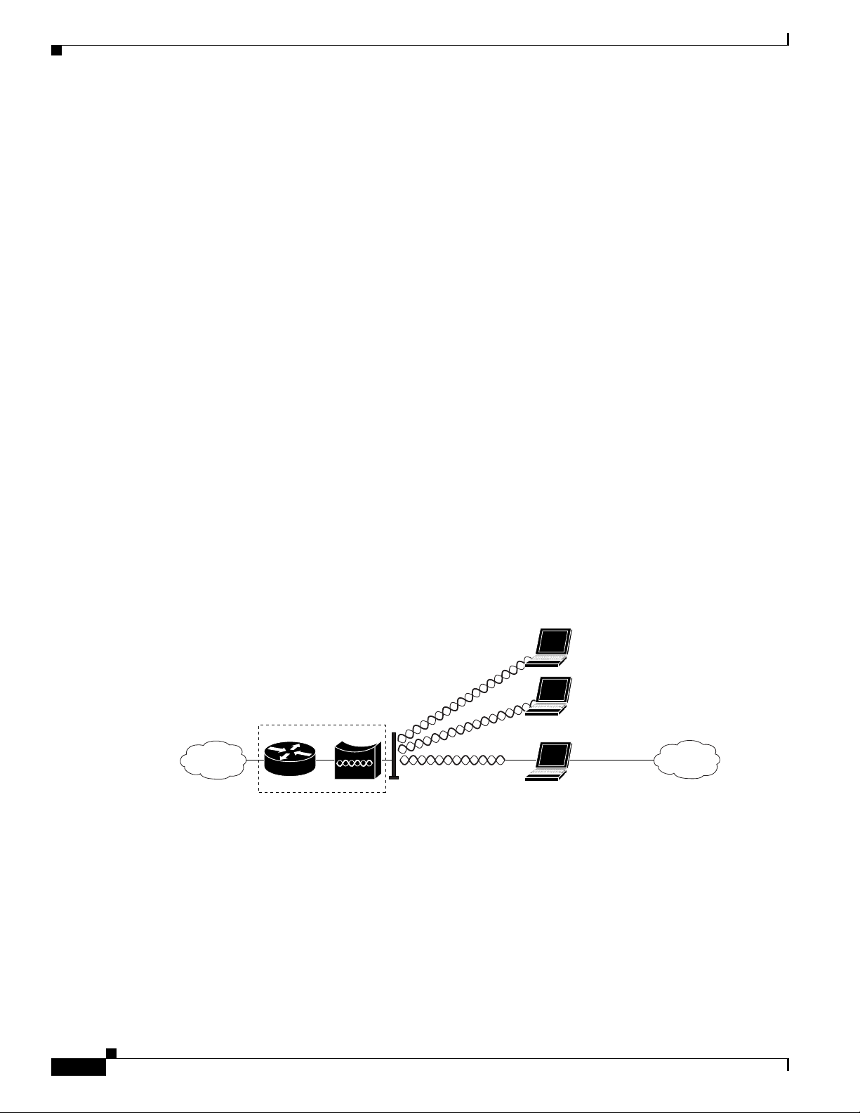
Access Point Mode
You can configure the WMIC as an access point. In the access point mode, the WMIC accepts
associations from local client devices. See Chapter 4, “Configuring Radio Settings,” for instructions on
configuring the WMIC as an access point.
Figure 1-1 shows a typical scenario where the WMIC functions as an access point.
Figure 1-1 Access Point Mode
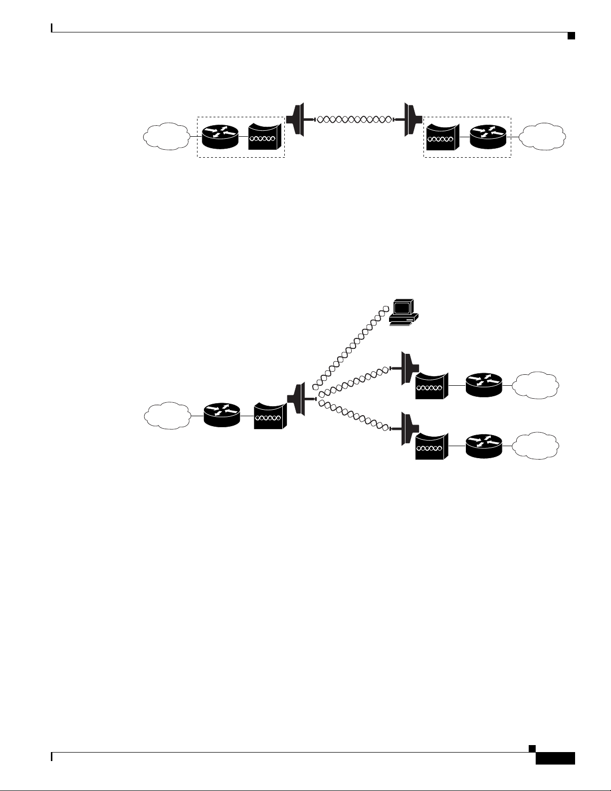
Point-to-Point Bridging
In a point-to-point configuration, a non-root bridge associates to a root bridge. The WMIC listens for
another bridge. If it does not recognize another bridge, the WMIC becomes a root bridge. If it recognizes
another bridge, it becomes a non-root bridge associated to the bridge it recognizes.
Cisco 3200
127919
1-2
Figure 1-2 shows bridges in a point-to-point configuration.
Cisco 3200 Series Wireless MIC Software Configuration Guide
OL-7734-02
Page 27
Chapter 1 Overview
Figure 1-2 Point-to-Point Bridge Configuration
Point-to-Multipoint Bridging
In a point-to-multipoint configuration, two or more non-root bridges associate to a root bridge. Up to 17
non-root bridges can associate to a root bridge, but the non-root bridges must share the available
bandwidth.
Figure 1-3 shows bridges in a point-to-multipoint configuration.
Figure 1-3 Point-to-Multipoint Configuration
Understanding the Cisco Mobile Wireless Network
127920
OL-7734-02
117021
Cisco 3200 Series Wireless MIC Software Configuration Guide
1-3
Page 28
Features
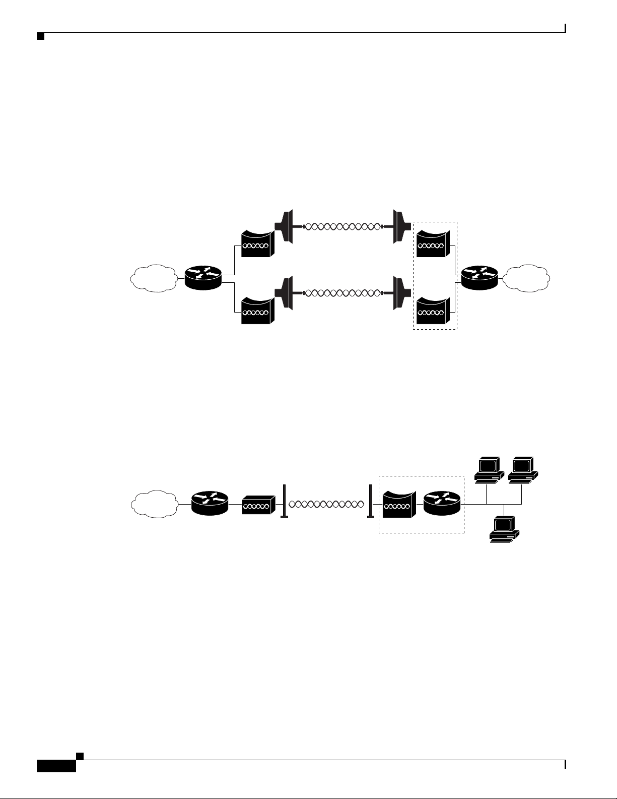
Redundant Bridging
You can set up two pairs of bridges to add redundancy or load balancing to the bridge link. The bridges
must use non-adjacent, non-overlapping radio channels to prevent interference, and they must use
Spanning Tree Protocol (STP) to prevent loops. (STP is disabled by default. See Chapter 6, “Configuring
Spanning Tree Protocol,” for instructions on configuring STP.)
Figure 1-4 shows two pairs of redundant bridges.
Figure 1-4 Redundant Bridge Configuration
Chapter 1 Overview
Cisco 3200
Workgroup Bridge Mode
You can configure the WMIC to function as a workgroup bridge. Figure 1-5 shows a typical scenario
where the WMIC functions as a workgroup bridge. See Chapter 4, “Configuring Radio Settings,” for
instructions on how to configure the WMIC as a workgroup bridge.
Figure 1-5 Workgroup Bridge Mode
Features
Cisco wireless devices running Cisco IOS offer these software features:
• VLANs—Allow VLAN trunking on both wireless and Ethernet interfaces.
• QoS—Use this feature to support quality of service for prioritizing traffic on the wireless interface.
127922
Cisco 3200
127923
1-4
• RADIUS Accounting—Enable accounting on the WMIC to send accounting data about wireless
client devices to a RADIUS server on your network.
• TACACS+ administrator authentication—Enable TACACS+ for server-based, detailed accounting
information and flexible administrative control over authentication and authorization processes. It
provides secure, centralized validation of administrators attempting to gain access to your WMIC.
Cisco 3200 Series Wireless MIC Software Configuration Guide
OL-7734-02
Page 29

Chapter 1 Overview
Note The 4.9-GHz WMIC does not support CKIP and CMIC encryption; however, The 2.4-GHz WMIC does
Features
• Enhanced security—Enable three advanced security features to protect against sophisticated attacks
on your wireless network's WEP keys: Message Integrity Check (MIC) and WEP key hashing.
Enhanced security for WPA/TKIP is also available.
• Enhanced authentication services—Set up non-root bridges or workgroup bridges to authenticate to
the network like other wireless client devices. After a network username and password for the
non-root bridge or workgroup bridge are set, it authenticates to the network using Cisco Light
Extensible Authentication Protocol (LEAP), and receives and uses dynamic WEP keys.
• Advanced Encryption Standard (AES) (only available on the 4.9-GHz WMIC)—This feature
supports Advanced Encryption Standard-Counter Mode with Cipher Block Chaining Message
Authentication Code Protocol (AES-CCMP). AES-CCMP is required for Wi-Fi Protected Access 2
(WPA2) and IEEE 802.11i wireless LAN security.
• Enhanced authentication for Cisco Centralized Key Management (CCKM).
• Fast, secure roaming of client devices, and radio management through wireless domain services
(WDS) (See the “Configuring WDS, Fast Secure Roaming, and Radio Management” chapter for
more information.
support CKIP and CMIC encryption.
The key differences between the 2.4-GHz WMIC and the 4.9-GHz WMIC are shown in Tab le 1-1.
Table 1-1 Differences Between the 2.4-GHz WMIC and the 4.9-GHz WMIC
Feature 2.4-GHz WMIC 4.9-GHz WMIC Comment
Cookie and
C3201 C32XX
Banner
Frequency 2.4 GHz 4.9 GHz
Data rates 802.11b data rates are
1 Mbps, 2 Mbps, 5.5 Mbps
and 11 Mbps.
802.11g, data rates are
1 Mbps, 2 Mbps, 5.5 Mbps,
6 Mbps, 9 Mbps, 11 Mbps,
12 Mbps, 18 Mbps, 24 Mbps,
36 Mbps, 48 Mbps, and
54 Mbps
20-MHz base band. 6 Mbps,
9 Mbps, 12 Mbps, 24 Mbps,
36 Mbps, 48 Mbps, and
56 Mbps.
10-MHz base band. Data
rates are 3 Mbps, 4.5 Mbps,
6 Mbps, 9 Mbps, 12 Mbps,
18 Mbps, 24 Mbps, and
27 Mbps.
The dot11 interface speed command
manages data rates and only applies to the
4.9-GHz WMIC.
5-MHz base band. Data
rates are 1.5 Mbps,
2.25 Mbps, 3 Mbps,
4.5 Mbps, 6 Mbps, 9 Mbps,
12 Mbps, and 13.5 Mbps
Power Maximum OFDM power
level is 15 dBm (30mw). This
varies by country.
Maximum OFDM power
level is 17 dBm (50mw). US
only.
The dot11 interface power command is
used to manage the power levels.
Concatenation Supported Not supported
OL-7734-02
Cisco 3200 Series Wireless MIC Software Configuration Guide
1-5
Page 30

Features
Table 1-1 Differences Between the 2.4-GHz WMIC and the 4.9-GHz WMIC
Feature 2.4-GHz WMIC 4.9-GHz WMIC Comment
distance
command
(minimizes delay
Supported Supported Formula to minimize the delay propagation
will be added to the dot11 interface
distance command
propagation)
World Mode Supported Not supported
HTML-Based
Supported Not supported
User Interface
VLAN 16 unencrypted VLANs
16 static key VLANs
16 dynamic key VLANs
16 unencrypted VLANs
1 static key VLANs
or
4 dynamic key VLANs
Wireless
encryption/cipher
suites
Maximum
WEP-40, WEP-128, TKIP,
CKIP, CMIC, and
WEP-40, WEP-128, TKIP,
and AES-CCM
CKIP-CMIC
255 116
CKIP, CMIC and CKIP-CMIC are not part
of 802.11 standard cipher suites.
number of
stations with
WEP
Maximum
256 26
number of
stations with
TKIP
Maximum
256 116
number of
stations with
AES-CCM
Channelization Statically declared as defined
by IEEE 802.11b/g.
Channel spacing selected by
using the CLI.
WDS server Not supported Can be configured to act as
WDS server.
WDS client 2.4 GHz WMIC
(C3201-WMIC) acting as
Root device can
auto-discover a WDS server.
Acting as Root device, it can
auto-discover and work
within a subnet WDS server.
If the IP address of a WDS server is
statically configured, the 4.9-GHz WMIC,
acting as Root device, can also work with
central WDS server located anywhere in the
network.
Chapter 1 Overview
1-6
Cisco 3200 Series Wireless MIC Software Configuration Guide
OL-7734-02
Page 31

Chapter 1 Overview
Management Options
Table 1-1 Differences Between the 2.4-GHz WMIC and the 4.9-GHz WMIC
Feature 2.4-GHz WMIC 4.9-GHz WMIC Comment
Scanning
Enhancements
for Faster
Roaming
All Scanning Enhancements
for Faster Roaming are
available.
All Scanning Enhancements
for Faster Roaming are
available except “Use First
Better Access Point.”
• Synthesizer tuning time
• Start on Current Channel
• Only Probe Current SSID
• Shorten Wait time for Probe Response
• Automatically Limiting Frequencies
Scanned
• Time out the Scan
• Use First Better Access Point
• Save Best Probe Response
EAP-TLS,
Supported on root devices Not supported
EAP-TTLS
SNMP MIB Ids Supported Supported (new values) The platform-dependent SNMP code was
modified to return new values.
(entPhysicalVendorType, System OID, and
Chassis ID)
Dot11 MIB
parameters
Not available The dot11 parameters are
returned through the dot11
MIB interface.
WDS
Not available Supported
server-related
MIBS
Management Options
You can use the WMIC management system through the following interfaces:
• The IOS command-line interface (CLI), which you use through a PC running terminal emulation
software or a Telnet session. Appendix A, “Connecting to the Cisco 3200 Series Router and Using
the Command-Line Interface,” provides a detailed description of how the CLI is used to confugure
the router. The “Preface” describes the command formats.
• Simple Network Management Protocol (SNMP). Chapter 14, “Configuring SNMP,” explains how to
configure your bridge for SNMP management.
OL-7734-02
Cisco 3200 Series Wireless MIC Software Configuration Guide
1-7
Page 32

Management Options
Chapter 1 Overview
1-8
Cisco 3200 Series Wireless MIC Software Configuration Guide
OL-7734-02
Page 33

CHA P T E R
2
Configuring the WMIC for the First Time
This chapter describes how to configure basic settings on a Wireless Mobile Interface Card (WMIC) for
the first time. You can configure all the settings described in this chapter using the CLI, but it might be
simplest to browse to the web-browser interface to complete the initial configuration and use the CLI to
enter additional settings for a more detailed configuration.
This chapter contains these sections:
• Before You Start
• Connecting to the WMIC
• Obtaining and Assigning an IP Address
• Obtaining and Assigning an IP Address
• Configuring Basic Security Settings
• Using the IP Setup Utility
OL-7734-02
Cisco 3200 Series Wireless MIC Software Configuration Guide
2-9
Page 34

Before You Start
Before You Start
Before you install the WMIC, make sure you are using a computer connected to the same network as the
WMIC, and obtain the following information from your network administrator:
• A system name for the WMIC
• The case-sensitive wireless service set identifier (SSID) that your WMICs use
• If not connected to a DHCP server, a unique IP address for your WMIC (such as 172.17.255.115)
• If the WMIC is not on the same subnet as your PC, a default gateway address and subnet mask
• A Simple Network Management Protocol (SNMP) community name and the SNMP file attribute (if
SNMP is in use)
Connecting to the WMIC
To configure the WMIC locally (without connecting the WMIC to a wired LAN), connect a PC to the
console port. If the WMIC has an IP address and Telnet is allowed on the device, connect to a Fast
Ethernet Switch Mobile Interface Card (FESMIC) Ethernet port by using an Ethernet cable, and use
Telnet to establish the connection. Or you can Telnet into the WMIC from a node on the LAN.
Chapter 2 Configuring the WMIC for the First Time
Note When you connect your PC to the WMIC or reconnect your PC to the LAN, it might be necessary to
release and renew the IP address on the PC. On most PCs, release and renew the IP address by rebooting
the PC or by entering the ipconfig /release and ipconfig /renew commands in a command window.
Consult your PC operating instructions for detailed instructions.
Using the Console Port to Access the Exec
Connect a PC to the WMIC console port by using a DB-9 to RJ-45 serial cable. Note that there might be
several console ports on a Cisco 3200 Series router.
Follow these steps to access the CLI by connecting to the WMIC console port:
Step 1 Connect a nine-pin, female DB-9 to RJ-45 serial cable to the WMIC RJ-45 serial port on the router and
to the COM port on your PC.
Step 2 Set up a terminal emulator to communicate with the WMIC. Use the following settings for the terminal
emulator connection: 9600 baud, 8 data bits, no parity, 1 stop bit, and no flow control.
Step 3 When the terminal emulator is activated, press Enter. An Enter Network Password window appears.
Step 4 Enter your username in the User Name field. The default username is Cisco.
Step 5 Enter the WMIC password in the Password field and press Enter. The default password is Cisco.
When the CLI activates, you can enter CLI commands to configure the WMIC.
2-10
Cisco 3200 Series Wireless MIC Software Configuration Guide
OL-7734-02
Page 35

Chapter 2 Configuring the WMIC for the First Time
Using a Telnet Session to Access the Exec
Follow these steps to access the WMIC CLI by using a Telnet session. The WMIC must have been
previously configured to accept a Telnet session.
These steps are for a PC running Microsoft Windows with a Telnet terminal application. Check the PC
operating instructions for detailed instructions for your operating system.
Step 1 Select Start > Programs > Accessories > Telnet.
If Telnet is not listed in your Accessories menu, select Start > Run, type Tel ne t in the entry field, and
press Enter.
Step 2 When the Telnet window appears, click Connect and select Remote System.
Note In Windows 2000, the Telnet window does not contain drop-down menus. To start the Telnet
session in Windows 2000, type open followed by the WMIC IP address.
Step 3 In the Host Name field, type the WMIC IP address and click Connect.
Connecting to the WMIC
Opening the CLI with Secure Shell
Secure Shell Protocol is a protocol that provides a secure, remote connection to networking devices set
up to use it. Secure Shell (SSH) is a software package that provides secure login sessions by encrypting
the entire session. SSH features strong cryptographic authentication, strong encryption, and integrity
protection. For detailed information on SSH, visit the homepage of SSH Communications Security, Ltd.
at this URL: http://www.ssh.com/
SSH provides more security for remote connections than Telnet by providing strong encryption when a
device is authenticated. See the “Configuring the WMIC for Secure Shell” section for instructions on
setting up the WMIC for SSH access.
OL-7734-02
Cisco 3200 Series Wireless MIC Software Configuration Guide
2-11
Page 36

Obtaining and Assigning an IP Address
Obtaining and Assigning an IP Address
To browse to the WMIC Express Setup page, you must assign the WMIC IP address using one of the
following methods:
• Use command when you connect to the WMIC locally. For detailed instructions, see the
“Connecting to the WMIC” section of this document.
• Use a DHCP server (if available) to automatically assign an IP address. You can find out the
DHCP-assigned IP address using one of the following methods:
–
Provide your organization’s network administrator with your WMIC Media Access Control
(MAC) address. Your network administrator will query the DHCP server using the MAC
address to identify the IP address.
–
Use the Cisco IP Setup Utility (IPSU) to identify the assigned address. You can also use IPSU
to assign an IP address to the WMIC if it did not receive an IP address from the DHCP server.
IPSU runs on most Microsoft Windows operating systems: Windows 9x, 2000, Me, NT, and XP.
You can download IPSU from the Software Center on Cisco.com. Click this link to browse to
the Software Center:
http://www.cisco.com/public/sw-center/sw-wireless.shtml
–
If the unit is a non-root bridge, browse to the Associations page on the root bridge to which the
non-root is associated. The non-root bridge’s MAC address and IP address appear on the root
bridge’s Associations page.
Chapter 2 Configuring the WMIC for the First Time
Assigning an IP Address By Using the Exec
The WMIC links to the network using a Bridge Group Virtual Interface (BVI) that it creates
automatically. Instead of tracking separate IP addresses for the WMIC Ethernet and radio ports, the
network uses the BVI.
Note The WMIC supports only one BVI. Configuring more than one BVI might cause errors in the WMIC
ARP table.
When you assign an IP address to the WMIC using the CLI, you must assign the address to the BVI.
Beginning in privileged EXEC mode, follow these steps to assign an IP address to the BVI:
Command Purpose
Step 1
Step 2
Step 3
configure terminal Enter global configuration mode.
interface bvi1 Enter interface configuration mode for the BVI.
ip address address
mask
Assign an IP address and address mask to the BVI.
Note If you are connected to the WMIC using a Telnet session, you lose
your connection to the WMIC when you assign a new IP address to
the BVI. To continue configuring the WMIC using Telnet, use the
new IP address to open another Telnet session to the WMIC.
2-12
Cisco 3200 Series Wireless MIC Software Configuration Guide
OL-7734-02
Page 37

Chapter 2 Configuring the WMIC for the First Time
Assigning Basic Settings By Using the Web Browser
After you determine or assign the WMIC IP address, browse to the Express Setup page and perform an
initial configuration:
Step 1 Open your Internet browser. The web-browser interface is fully compatible with these browsers:
Microsoft Internet Explorer versions 5.0, 5.01, 5.5 and 6.0; and Netscape Navigator versions 4.79 and
7.0.
Step 2 Enter the IP address in the browser address line and press Enter. An Enter Network Password screen
appears.
Step 3 Press Ta b to bypass the Username field and advance to the Password field.
Step 4 Enter the case-sensitive password (usually Cisco) and press Enter. The Summary Status page appears.
Figure 2-1 shows the Summary Status page.
Figure 2-1 Summary Status Page
Obtaining and Assigning an IP Address
OL-7734-02
Step 5
Click Express Setup. The Express Setup screen appears. Figure 2-2 shows the Express Setup page.
Cisco 3200 Series Wireless MIC Software Configuration Guide
2-13
Page 38

Obtaining and Assigning an IP Address
Figure 2-2 Express Setup Page
Chapter 2 Configuring the WMIC for the First Time
Step 6
Enter the configuration settings you obtained from your system administrator. The configurable settings
include:
• System Name— The system name, while not an essential setting, helps identify the WMIC on your
network. The system name appears in the titles of the management system pages.
• Configuration Server Protocol—Click on the button that matches the network’s method of IP
address assignment.
–
DHCP—IP addresses are automatically assigned by your network’s DHCP server.
–
Static IP—The WMIC uses a static IP address that you enter in the IP address field.
• IP Address—Use this setting to assign or change the WMIC’s IP address. If DHCP is enabled for
your network, leave this field blank.
Note If the WMIC IP address changes while you are configuring the WMIC using the web-browser
interface or a Telnet session over the wired LAN, you lose your connection to the WMIC. If you
lose your connection, reconnect to the WMIC using its new IP address. Follow the steps in the
“Obtaining and Assigning an IP Address” section on page 2-12 if you need to start over.
• IP Subnet Mask—Enter the IP subnet mask provided by your network administrator so the IP
address can be recognized on the LAN. If DHCP is enabled, leave this field blank.
• Default Gateway—Enter the default gateway IP address provided by your network administrator.
If DHCP is enabled, leave this field blank.
2-14
Cisco 3200 Series Wireless MIC Software Configuration Guide
OL-7734-02
Page 39

Chapter 2 Configuring the WMIC for the First Time
• SNMP Community—If your network is using SNMP, enter the SNMP Community name provided
by your network administrator and select the attributes of the SNMP data (also provided by your
network administrator).
• Role in Radio Network—Click on the button that describes the role of the device on your network.
–
Root—Configures the device as a root bridge. In this mode, you establish a link with a non-root
bridge. In this mode, the bridge also accepts associations from clients.
–
Non-Root— Places the device in non-root mode. In this mode, it links with a root bridge.
–
Install Mode—Places the device into installation mode so you can align and adjust the bridge
link for optimum efficiency.
–
Root AP—Places the device in the access point mode. In this mode, the device accepts
associations from client devices.
–
Workgroup Bridge—Places the device in the workgroup bridge mode. In this mode, the bridge
accepts wired clients.
Note In bridge modes, one bridge in any pair or group of bridges must be set to root, and the bridge
or bridges associated to the root bridge must be set to non-root.
Obtaining and Assigning an IP Address
• Optimize Radio Network for—Use this setting to select either preconfigured settings or
customized settings for the bridge radio. See the “Configuring the Radio Distance Setting” section
on page 4-14 for more information on data rates and throughput.
–
Throughput—Maximizes the data volume handled by the WMIC but might reduce its range.
When you select Throughput, the WMIC sets all data rates to basic.
–
Range—Maximizes the WMIC’s range but might reduce throughput. When you select Range,
the WMIC sets the 6-Mbps rate to basic and the other rates to enabled.
–
Default—The WMIC retains default radio settings that are designed to provide good range and
throughput for most bridges.
–
Custom—Takes you to the Network Interfaces: Radio-802.11G Settings page.
• Aironet Extensions—Enabled by default, click the Disable Aironet Extensions radio button, and
click Apply. The change will not be made to the configuration if the device is in workgroup bridge
mode. In root bridge and non-root bridge mode, an error message displays, indicating that Aironet
Extensions should always be enabled in root or non-root mode.
Step 7 Click Apply to save your settings. If you changed the IP address, you lose your connection to the WMIC.
Browse to the new IP address to reconnect to the WMIC.
Your WMIC is now running but probably requires additional configuring to conform to your network’s
operational and security requirements.
OL-7734-02
Cisco 3200 Series Wireless MIC Software Configuration Guide
2-15
Page 40

Protecting Your Wireless LAN
Default Settings on the Express Setup Page
Table 2-1 lists the default settings for the settings on the Express Setup page.
Table 2-1 Default Settings on the Express Setup Page
Setting Default
System Name bridge
Configuration Server Protocol DHCP
IP Address Assigned by DHCP by default; if DHCP is disabled, the default
setting is 10.0.0.1
IP Subnet Mask Assigned by DHCP by default; if DHCP is disabled, the default
setting is 255.255.255.224
Default Gateway Assigned by DHCP by default; if DHCP is disabled, the default
setting is 0.0.0.0
SNMP Community defaultCommunity
Role in Radio Network Install-Mode
Optimize Radio Network for Default
Aironet Extensions Enable
Chapter 2 Configuring the WMIC for the First Time
Protecting Your Wireless LAN
After you assign basic settings to your WMIC, you must configure security settings to prevent
unauthorized access to your network. Because it is a radio device, the WMIC can communicate beyond
the physical boundaries of your building. You can use Express Security page in the Configuring Basic
Security Settings section to set basic security settings for your WMIC. Advanced security features can
be found in the following chapters:
• A unique SSID that are not broadcast in the beacon (see Chapter 5, “Configuring SSIDs”
• WEP and WEP features (see Chapter 7, “Configuring WEP and WEP Features”)
• Dynamic WEP and WMIC authentication (see Chapter 8, “Configuring Authentication Types”)
2-16
Cisco 3200 Series Wireless MIC Software Configuration Guide
OL-7734-02
Page 41

Chapter 2 Configuring the WMIC for the First Time
Configuring Basic Security Settings
After you assign basic settings to your access point, you must configure security settings to prevent
unauthorized access to your network. Because it is a radio device, the access point can communicate
beyond the physical boundaries of your worksite.
Just as you use the Express Setup page to assign basic settings, you can use the Express Security page
to create unique SSIDs and assign one of four security types to them. Figure 2-3 shows the Express
Security page.
Figure 2-3 Express Security Page
Protecting Your Wireless LAN
OL-7734-02
The Express Security page helps you configure basic security settings. You can use the web-browser
interface’s main Security pages to configure more advanced security settings.
Cisco 3200 Series Wireless MIC Software Configuration Guide
2-17
Page 42

Protecting Your Wireless LAN
Understanding Express Security Settings
When the WMIC configuration is at factory defaults, the first SSID that you create using the Express
security page overwrites the default SSID, install, which has no security settings. The SSIDs that you
create appear in the SSID table at the bottom of the page. You can create up to 16 SSIDs on the access
point.
Using VLANs
If you use VLANs on your wireless LAN and assign SSIDs to VLANs, you can create multiple SSIDs
using any of the four security settings on the Express Security page. However, if you do not use VLANs
on your wireless LAN, the security options that you can assign to SSIDs are limited because, on the
Express Security page, encryption settings and authentication types are linked. Without VLANs,
encryption settings (WEP and ciphers) apply to an interface such as the 2.4-GHz radio, and you cannot
use more than one encryption setting on an interface. For example, when you create an SSID with static
WEP with VLANs disabled, you cannot create additional SSIDs with WPA authentication because they
use different encryption settings. If you find that the security setting for an SSID conflicts with another
SSID, you can delete one or more SSIDs to eliminate the conflict.
Chapter 2 Configuring the WMIC for the First Time
Express Security Types
Table 2-2 describes the four security types that you can assign to an SSID.
Table 2-2 Security Types on Express Security Setup Page
Security Type Description Security Features Enabled
No Security This is the least secure option. You
Static WEP Key This option is more secure than no
should use this option only for SSIDs
used in a public space and assign it to
a VLAN that restricts access to your
network.
security. However, static WEP keys
are vulnerable to attack. If you
configure this setting, you should
consider limiting association to the
access point based on MAC address
or, if your network does not have a
RADIUS server, consider using an
access point as a local authentication
server.
None.
Mandatory WEP encryption, no key
management, and open
authentication. In Root AP mode,
client devices cannot associate using
this SSID without a WEP key that
matches the access point key.
2-18
Cisco 3200 Series Wireless MIC Software Configuration Guide
OL-7734-02
Page 43

Chapter 2 Configuring the WMIC for the First Time
Table 2-2 Security Types on Express Security Setup Page (continued)
Security Type Description Security Features Enabled
EAP Authentication This option enables 802.1x
WPA Wi-Fi Protected Access (WPA)
authentication (such as LEAP, PEAP,
EAP-TLS, EAP-GTC, EAP-SIM, and
others) and requires you to enter the
IP address and shared secret for an
authentication server on your network
(server authentication port 1645).
Because 802.1x authentication
provides dynamic encryption keys,
you do not need to enter a WEP key.
permits wireless access to users
authenticated against a database
through the services of an
authentication server, then encrypts
their IP traffic with stronger
algorithms than those used in WEP.
As with EAP authentication, you
must enter the IP address and shared
secret for an authentication server on
your network (server authentication
port 1645).
Protecting Your Wireless LAN
Mandatory 802.1x authentication, In
Root AP mode, client devices that
associate using this SSID must
perform 802.1x authentication.
Mandatory WPA authentication. In
Root AP mode, client devices that
associate using this SSID must be
WPA-capable.
Express Security Limitations
Because the Express Security page is designed for simple configuration of basic security, the options
available are a subset of the WMIC’s security capabilities. Keep these limitations in mind when using
the Express Security page:
• You cannot edit SSIDs. However, you can delete SSIDs and re-create them.
• You cannot assign SSIDs to specific radio interfaces. The SSIDs that you create are enabled on all
radio interfaces. To assign SSIDs to specific radio interfaces, use the Security SSID Manager page.
• You cannot configure multiple authentication servers. To configure multiple authentication servers,
use the Security Server Manager page.
• You cannot configure multiple WEP keys. To configure multiple WEP keys, use the Security
Encryption Manager page.
• You cannot assign an SSID to a VLAN that is already configured on the WMIC. To assign an SSID
to an existing VLAN, use the Security SSID Manager page.
• You cannot configure combinations of authentication types on the same SSID (for example, MAC
address authentication and EAP authentication). To configure combinations of authentication types,
use the Security SSID Manager page.
OL-7734-02
Cisco 3200 Series Wireless MIC Software Configuration Guide
2-19
Page 44

Protecting Your Wireless LAN
Using the Express Security Page
Follow these steps to create an SSID using the Express Security page:
Step 1 Type the SSID in the SSID entry field. The SSID can contain up to 32 alphanumeric characters.
a. The Broadcast SSID in Beacon setting is active only when the WMIC is in the Root AP mode.
When you broadcast the SSID, devices that do not specify an SSID can associate to the WMIC when
it is a root access point. This is a useful option for an SSID used by guests or by client devices in a
public space. If you do not broadcast the SSID, client devices cannot associate to the access point
unless their SSID matches this SSID. Only one SSID can be included in the beacon.
Step 2 (Optional) Check the Enable VLAN ID check box and enter a VLAN number (1 through 4095) to assign
the SSID to a VLAN. You cannot assign an SSID to an existing VLAN.
Step 3 (Optional) Check the Native VLAN check box to mark the VLAN as the native VLAN.
Step 4 Select the security setting for the SSID. The settings are listed in order of robustness, from No Security
to WPA, which is the most secure setting. If you select EAP Authentication or WPA, enter the IP address
and shared secret for the authentication server on your network.
Chapter 2 Configuring the WMIC for the First Time
Note If you do not use VLANs on your wireless LAN, the security options that you can assign to multiple
SSIDs are limited. See the “Using VLANs” section on page 2-18 for details.
Step 5 Click Apply. The SSID appears in the SSID table at the bottom of the page.
CLI Security Configuration Examples
The examples in this section show the CLI commands that are equivalent to creating SSIDs using each
security type on the Express Security page. This section contains these example configurations:
• Example: No Security, page 2-20
• Example: Static WEP, page 2-21
• Example: EAP Authentication, page 2-22
• Example: WPA, page 2-23
Example: No Security
This example shows part of the configuration that results from using the Express Security page to create
an SSID called no_security_ssid, including the SSID in the beacon, assigning it to VLAN 10, and
selecting VLAN 10 as the native VLAN:
interface Dot11Radio0
no ip address
no ip route-cache
!
ssid no_security-ssid
vlan 10
authentication open
guest-mode
!
!
2-20
Cisco 3200 Series Wireless MIC Software Configuration Guide
OL-7734-02
Page 45

Chapter 2 Configuring the WMIC for the First Time
concatenation
speed basic-1.0 basic-2.0 basic-5.5 6.0 9.0 basic-11.0 12.0 18.0 24.0 36.0 48.0 54.0
rts threshold 4000
station-role root
infrastructure-client
bridge-group 1
!
interface Dot11Radio0.10
encapsulation dot1Q 10
no ip route-cache
bridge-group 10
bridge-group 10 spanning-disabled
!
interface FastEthernet0
no ip address
no ip route-cache
duplex auto
speed auto
bridge-group 1
!
interface FastEthernet0
no ip address
no ip route-cache
duplex auto
speed auto
bridge-group 1
Protecting Your Wireless LAN
Example: Static WEP
This example shows part of the configuration that results from using the Express Security page to create
an SSID called static_wep_ssid, excluding the SSID from the beacon, assigning the SSID to VLAN 20,
selecting 3 as the key slot, and entering a 128-bit key:
interface Dot11Radio0
no ip address
no ip route-cache
!
encryption vlan 20 key 3 size 128bit 7 4E78330C1A841439656A9323F25A transmit-ke
y
encryption vlan 20 mode wep mandatory
!
ssid static_wep_ssid
vlan 20
authentication open
!
concatenation
speed basic-1.0 basic-2.0 basic-5.5 6.0 9.0 basic-11.0 12.0 18.0 24.0 36.0 48.0 54.0
rts threshold 4000
station-role root
infrastructure-client
bridge-group 1
!
interface Dot11Radio0.20
encapsulation dot1Q 20
no ip route-cache
bridge-group 20
bridge-group 20 spanning-disabled
!
interface FastEthernet0
no ip address
no ip route-cache
duplex auto
OL-7734-02
Cisco 3200 Series Wireless MIC Software Configuration Guide
2-21
Page 46

Protecting Your Wireless LAN
speed auto
bridge-group 1
!
interface FastEthernet0.20
encapsulation dot1Q 20
no ip route-cache
bridge-group 20
bridge-group 20 spanning-disabled
Example: EAP Authentication
This example shows part of the configuration that results from using the Express Security page to create
an SSID called eap_ssid, excluding the SSID from the beacon, and assigning the SSID to VLAN 30:
interface Dot11Radio0
no ip address
no ip route-cache
!
encryption vlan 30 mode wep mandatory
!
ssid eap_ssid
vlan 30
authentication open eap eap_methods
authentication network-eap eap_methods
!
speed basic-1.0 basic-2.0 basic-5.5 basic-11.0
rts threshold 2312
station-role root
bridge-group 1
bridge-group 1 subscriber-loop-control
bridge-group 1 block-unknown-source
no bridge-group 1 source-learning
no bridge-group 1 unicast-flooding
bridge-group 1 spanning-disabled
!
interface Dot11Radio0.30
encapsulation dot1Q 30
no ip route-cache
bridge-group 30
bridge-group 30 subscriber-loop-control
bridge-group 30 block-unknown-source
no bridge-group 30 source-learning
no bridge-group 30 unicast-flooding
bridge-group 30 spanning-disabled
!
interface FastEthernet0
mtu 1500
no ip address
ip mtu 1564
no ip route-cache
duplex auto
speed auto
bridge-group 1
no bridge-group 1 source-learning
bridge-group 1 spanning-disabled
!
Chapter 2 Configuring the WMIC for the First Time
2-22
Cisco 3200 Series Wireless MIC Software Configuration Guide
OL-7734-02
Page 47

Chapter 2 Configuring the WMIC for the First Time
interface FastEthernet0.30
mtu 1500
encapsulation dot1Q 30
no ip route-cache
bridge-group 30
no bridge-group 30 source-learning
bridge-group 30 spanning-disabled
Example: WPA
This example shows part of the configuration that results from using the Express Security page to create
an SSID called wpa_ssid, excluding the SSID from the beacon, and assigning the SSID to VLAN 40:
aaa new-model
!
aaa group server radius rad_eap
server 10.91.104.92 auth-port 1645 acct-port 1646
!
aaa group server radius rad_mac
!
aaa group server radius rad_acct
!
aaa group server radius rad_admin
!
aaa group server tacacs+ tac_admin
!
aaa group server radius rad_pmip
!
aaa group server radius dummy
!
aaa authentication login eap_methods group rad_eap
aaa authentication login mac_methods local
aaa authorization exec default local
aaa authorization ipmobile default group rad_pmip
aaa accounting network acct_methods start-stop group rad_acct
aaa session-id common
!
!
bridge irb
!
!
interface Dot11Radio0
no ip address
no ip route-cache
!
encryption vlan 40 mode ciphers tkip
!
ssid wpa_ssid
vlan 40
authentication open eap eap_methods
authentication network-eap eap_methods
authentication key-management wpa
!
concatenation
speed basic-1.0 basic-2.0 basic-5.5 6.0 9.0 basic-11.0 12.0 18.0 24.0 36.0 48 54.0
rts threshold 4000
station-role root
infrastructure-client
bridge-group 1
!
interface Dot11Radio0.40
encapsulation dot1Q 40
Protecting Your Wireless LAN
OL-7734-02
Cisco 3200 Series Wireless MIC Software Configuration Guide
2-23
Page 48

Using the IP Setup Utility
Chapter 2 Configuring the WMIC for the First Time
no ip route-cache
bridge-group 40
!
interface FastEthernet0
no ip address
no ip route-cache
duplex auto
speed auto
bridge-group 1
!
interface FastEthernet0.40
encapsulation dot1Q 40
no ip route-cache
bridge-group 40
!
ip http server
ip http help-path http://www.cisco.com/warp/public/779/smbiz/prodconfig/help/eag
/122-15.JA/1100
ip radius source-interface BVI1
radius-server attribute 32 include-in-access-req format %h
radius-server host 10.91.104.92 auth-port 1645 acct-port 1646 key 7 135445415F59
radius-server authorization permit missing Service-Type
radius-server vsa send accounting
bridge 1 route ip
!
line con 0
line vty 5 15
!
end
Using the IP Setup Utility
IPSU enables you to find the IP address of a device when it has been assigned by a DHCP server. You
can also use IPSU to set the IP address and SSID of a device if they have not been changed from the
default settings. This section explains how to download the utility from Cisco.com and install it, how to
use it to find the IP address of a device, and how to use it to set the IP address and the SSID.
Note IPSU can be used only on the following operating systems: Windows 95, 98, NT, 2000, ME, or XP.
Obtaining and Installing IPSU
IPSU is available on the Cisco web site. Follow these steps to obtain and install IPSU:
Step 1 Use your Internet browser to access the Cisco Software Center at the following URL:
http://www.cisco.com/public/sw-center/sw-wireless.shtml
Step 2 Click Cisco Aironet Wireless LAN Client Adapters.
Step 3 Scroll down to the Windows Utility section.
Step 4 Click Cisco Aironet Client Utility (ACU) for Windows.
Step 5 Click the file IPSUvxxxxxx.exe. The vxxxxxx identifies the software package version number.
Step 6 Read and accept the terms and conditions of the Software License Agreement.
2-24
Cisco 3200 Series Wireless MIC Software Configuration Guide
OL-7734-02
Page 49

Chapter 2 Configuring the WMIC for the First Time
Step 7 Download and save the file to a temporary directory on your hard drive and then exit the Internet browser.
Step 8 Double-click IPSUvxxxxxx.exe in the temporary directory to expand the file.
Step 9 Double-click Setup.exe and follow the steps provided by the installation wizard to install IPSU.
The IPSU icon appears on your computer desktop.
Using IPSU to Find the WMIC IP Address
If your WMIC receives an IP address from a DHCP server, you can use IPSU to find its IP address.
Because IPSU sends a reverse-ARP request based on the MAC address, you must run IPSU from a
computer on the same subnet as the WMIC. Follow these steps to find the IP address:
Step 1 Double-click the IPSU icon on your computer desktop to start the utility. The IPSU screen appears (see
Figure 2-4).
Figure 2-4 IPSU Get IP Address Screen
Using the IP Setup Utility
OL-7734-02
Step 2
Step 3 Enter the WMIC MAC address in the Device MAC ID field. The WMIC MAC address should contain
When the utility window opens, make sure the Get IP addr radio button in the Function box is selected.
six pairs of hexadecimal digits. The MAC address might look like the following example:
000164xxxxxx
Note The MAC address field is not case-sensitive.
Step 4 Click Get IP Address.
Step 5 When the IP address appears in the IP Address field, write it down.
If IPSU reports that the IP address is the default IP address, the WMIC did not receive a DHCP-assigned
IP address. To change the IP address by using IPSU, refer to the “Using IPSU to Set the IP Address and
SSID” section.
Cisco 3200 Series Wireless MIC Software Configuration Guide
2-25
Page 50

Using the IP Setup Utility
Using IPSU to Set the IP Address and SSID
To change the IP address of the WMIC, use IPSU. You can also set the SSID.
Note IPSU can change the IP address and SSID only from the default settings. After the IP address and SSID
have been changed, IPSU cannot be used to change them again.
Note The computer you use to assign an IP address to the WMIC must have an IP address in the same subnet
as the WMIC.
Follow these steps to assign an IP address and an SSID to the WMIC:
Step 1 Double-click the IPSU icon on your computer desktop to start the utility.
Step 2 Click the Set Parameters radio button in the Function box (see Figure 2-5).
Chapter 2 Configuring the WMIC for the First Time
Figure 2-5 IPSU Set Parameters Screen
Step 3
Enter the WMIC MAC address in the Device MAC ID field. The MAC address should contain six pairs
of hexadecimal digits. Your MAC address might look like this example:
004096xxxxxx
Note The MAC address field is not case-sensitive.
Step 4 Enter the IP address you want to assign to the WMIC in the IP Address field.
2-26
Step 5 Enter the SSID you want to assign to the WMIC in the SSID field.
Note You cannot set the SSID without also setting the IP address. However, you can set the IP address
without setting the SSID.
Cisco 3200 Series Wireless MIC Software Configuration Guide
OL-7734-02
Page 51

Chapter 2 Configuring the WMIC for the First Time
Step 6 Click Set Parameters to change the WMIC’s IP address and SSID settings.
Step 7 Click Exit to exit IPSU.
Using the IP Setup Utility
OL-7734-02
Cisco 3200 Series Wireless MIC Software Configuration Guide
2-27
Page 52

Using the IP Setup Utility
Chapter 2 Configuring the WMIC for the First Time
2-28
Cisco 3200 Series Wireless MIC Software Configuration Guide
OL-7734-02
Page 53

CHA P T E R
Administering the WMIC
This chapter describes how to administer your WMIC. This chapter contains these sections:
• Configuring a System Name and Prompt
• Managing the System Time and Date
• Creating a Banner
• Protecting Access to Privileged EXEC Commands
• Protecting the Wireless LAN
• Controlling WMIC Access with RADIUS
• Controlling WMIC Access with TACACS+
• Configuring the WMIC for Local Authentication and Authorization
• Configuring the WMIC for Secure Shell
• Managing Aironet Extensions
3
OL-7734-02
Cisco 3200 Series Wireless MIC Software Configuration Guide
3-1
Page 54

Configuring a System Name and Prompt
Configuring a System Name and Prompt
You configure the system name on the WMIC to identify it. A greater-than symbol (>) is appended. The
prompt is updated whenever the system name changes, unless you manually configure the prompt by
using the prompt global configuration command.
Note For complete syntax and usage information for the commands used in this section, refer to the Cisco IOS
Configuration Fundamentals Command Reference and the Cisco IOS IP and IP Routing Command
Reference for Release 12.1.
Configuring a System Name
Beginning in privileged EXEC mode, follow these steps to manually configure a system name:
Command Purpose
Step 1
Step 2
Step 3
Step 4
Step 5
configure terminal Enter global configuration mode.
hostname name Manually configure a system name.
The default setting is bridge.
The name must follow the rules for ARPANET host names. They must start
with a letter, end with a letter or digit, and have as interior characters only
letters, digits, and hyphens. Names can be up to 63 characters.
end Return to privileged EXEC mode.
show running-config Verify your entries.
copy running-config startup-config (Optional) Save your entries in the configuration file.
Chapter 3 Administering the WMIC
When you set the system name, it is also used as the system prompt.
To return to the default host name, use the no hostname global configuration command.
Managing DNS
The DNS protocol controls the Domain Name System (DNS), a distributed database with which you can
map host names to IP addresses. When you configure DNS on your WMIC, you can substitute the host
name for the IP address with all IP commands, such as ping, telnet, connect, and related Telnet support
operations.
IP defines a hierarchical naming scheme that allows a device to be identified by its location or domain.
Domain names are pieced together with periods (.) as the delimiting characters. For example, Cisco
Systems is a commercial organization that IP identifies by a com domain name, so its domain name is
cisco.com. A specific device in this domain, such as the File Transfer Protocol (FTP) system, is
identified as ftp.cisco.com.
To keep track of domain names, IP has defined the concept of a domain name server, which holds a cache
(or database) of names mapped to IP addresses. To map domain names to IP addresses, you must first
identify the host names, specify the name server that is present on your network, and enable the DNS.
Cisco 3200 Series Wireless MIC Software Configuration Guide
3-2
OL-7734-02
Page 55

Chapter 3 Administering the WMIC
Default DNS Configuration
Table 3-1 shows the default DNS configuration.
Table 3-1 Default DNS Configuration
Feature Default Setting
DNS enable state Disabled.
DNS default domain name None configured.
DNS servers No name server addresses are configured.
Setting Up DNS
Beginning in privileged EXEC mode, follow these steps to set up your WMIC to use the DNS:
Command Purpose
Step 1
Step 2
configure terminal Enter global configuration mode.
ip domain-name name Define a default domain name that the software uses to complete unqualified
Managing DNS
host names (names without a dotted-decimal domain name).
Do not include the initial period that separates an unqualified name from the
domain name.
Step 3
Step 4
Step 5
Step 6
Step 7
At boot time, no domain name is configured; however, if the configuration
comes from a BOOTP or Dynamic Host Configuration Protocol (DHCP) server,
then the default domain name might be set by the BOOTP or DHCP server (if
the servers were configured with this information).
ip name-server server-address1
[server-address2 ...
server-address6]
Specify the address of one or more name servers to use for name and address
resolution.
You can specify up to six name servers. Separate each server address with a
space. The first server specified is the primary server. The WMIC sends DNS
queries to the primary server first. If that query fails, the backup servers are
queried.
ip domain-lookup (Optional) Enable DNS-based host name-to-address translation on your WMIC.
This feature is enabled by default.
If your network devices require connectivity with devices in networks for which
you do not control name assignment, you can dynamically assign device names
that uniquely identify your devices by using the global Internet naming scheme
(DNS).
end Return to privileged EXEC mode.
show running-config Verify your entries.
copy running-config
(Optional) Save your entries in the configuration file.
startup-config
If you use the WMIC IP address as its host name, the IP address is used and no DNS query occurs. If
you configure a host name that contains no periods (.), a period followed by the default domain name is
appended to the host name before the DNS query is made to map the name to an IP address. The default
OL-7734-02
Cisco 3200 Series Wireless MIC Software Configuration Guide
3-3
Page 56

Creating a Banner
domain name is the value set by the ip domain-name global configuration command. If there is a
period (.) in the host name, the IOS software looks up the IP address without appending any default
domain name to the host name.
To remove a domain name, use the no ip domain-name name global configuration command. To remove
a name server address, use the no ip name-server server-address global configuration command. To
disable DNS on the WMIC, use the no ip domain-lookup global configuration command.
Displaying the DNS Configuration
To display the DNS configuration information, use the show running-config privileged EXEC
command.
Creating a Banner
You can configure a message-of-the-day (MOTD) and a login banner. The MOTD banner appears on all
connected terminals at login and is useful for sending messages that affect all network users (such as
impending system shutdowns).
The login banner also appears on all connected terminals. It appears after the MOTD banner and before
the login prompts.
Chapter 3 Administering the WMIC
Note For complete syntax and usage information for the commands used in this section, refer to the Cisco IOS
Configuration Fundamentals Command Reference for Release 12.2.
Default Banner Configuration
The MOTD and login banners are not configured.
Configuring a Message-of-the-Day Login Banner
You can create a single or multiline message banner that appears on the screen when someone logs into
the WMIC.
Beginning in privileged EXEC mode, follow these steps to configure a MOTD login banner:
Command Purpose
Step 1
Step 2
configure terminal Enter global configuration mode.
banner motd c message c Specify the message of the day.
For c, enter the delimiting character of your choice, such as a pound sign
(#), and press the Return key. The delimiting character signifies the
beginning and end of the banner text. Characters after the ending
delimiter are discarded.
For message, enter a banner message up to 255 characters. You cannot
use the delimiting character in the message.
3-4
Cisco 3200 Series Wireless MIC Software Configuration Guide
OL-7734-02
Page 57

Chapter 3 Administering the WMIC
Command Purpose
Step 3
Step 4
Step 5
end Return to privileged EXEC mode.
show running-config Verify your entries.
copy running-config startup-config (Optional) Save your entries in the configuration file.
To delete the MOTD banner, use the no banner motd global configuration command.
This example shows how to configure a MOTD banner for the WMIC using the pound sign (#) symbol
as the beginning and ending delimiter:
bridge(config)# banner motd #
This is a secure site. Only authorized users are allowed.
For access, contact technical support.
#
bridge(config)#
This example shows the banner displayed from the previous configuration:
Unix> telnet 172.2.5.4
Trying 172.2.5.4...
Connected to 172.2.5.4.
Escape character is '^]'.
Creating a Banner
This is a secure site. Only authorized users are allowed.
For access, contact technical support.
User Access Verification
Password:
Configuring a Login Banner
You can configure a login banner to appear on all connected terminals. This banner appears after the
MOTD banner and before the login prompt.
Beginning in privileged EXEC mode, follow these steps to configure a login banner:
Command Purpose
Step 1
Step 2
Step 3
Step 4
Step 5
configure terminal Enter global configuration mode.
banner login c message c Specify the login message.
end Return to privileged EXEC mode.
show running-config Verify your entries.
copy running-config startup-config (Optional) Save your entries in the configuration file.
For c, enter the delimiting character of your choice, such as a pound sign
(#), and press the Return key. The delimiting character signifies the
beginning and end of the banner text. Characters after the ending delimiter
are discarded.
For message, enter a login message up to 255 characters. You cannot use the
delimiting character in the message.
OL-7734-02
To delete the login banner, use the no banner login global configuration command.
Cisco 3200 Series Wireless MIC Software Configuration Guide
3-5
Page 58

Managing the System Time and Date
This example shows how to configure a login banner for the WMIC using the dollar sign ($) symbol as
the beginning and ending delimiter:
bridge(config)# banner login $
Access for authorized users only. Please enter your username and password.
$
bridge(config)#
Managing the System Time and Date
You can manage the system time and date on your WMIC automatically, using the Network Time
Protocol (NTP), or manually, by setting the time and date on the WMIC.
Note For complete syntax and usage information for the commands used in this section, refer to the Cisco IOS
Configuration Fundamentals Command Reference for Release 12.2.
Understanding the System Clock
Chapter 3 Administering the WMIC
The heart of the time service is the system clock. This clock runs from the moment the system starts up
and keeps track of the date and time.
The system clock can then be set from these sources:
• Network Time Protocol
• Manual configuration
The system clock can provide time to these services:
• User show commands
• Logging and debugging messages
The system clock determines time internally based on Universal Time Coordinated (UTC), also known
as Greenwich Mean Time (GMT). You can configure information about the local time zone and summer
time (daylight saving time) so that the time is correctly displayed for the local time zone.
The system clock keeps track of whether the time is authoritative or not (that is, whether it has been set
by a time source considered to be authoritative). If it is not authoritative, the time is available only for
display purposes and is not redistributed. For configuration information, see the “Configuring Time and
Date Manually” section on page 3-17.
Understanding Network Time Protocol
The NTP is designed to time-synchronize a network of devices. NTP runs over User Datagram Protocol
(UDP), which runs over IP. NTP is documented in RFC 1305.
3-6
An NTP network usually gets its time from an authoritative time source, such as a radio clock or an
atomic clock attached to a time server. NTP then distributes this time across the network. NTP is
extremely efficient; no more than one packet per minute is necessary to synchronize two devices to
within a millisecond of one another.
NTP uses the concept of a stratum to describe how many NTP hops away a device is from an
authoritative time source. A stratum 1 time server has a radio or atomic clock directly attached, a
stratum 2 time server receives its time through NTP from a stratum 1 time server, and so on. A device
Cisco 3200 Series Wireless MIC Software Configuration Guide
OL-7734-02
Page 59

Chapter 3 Administering the WMIC
running NTP automatically chooses as its time source the device with the lowest stratum number with
which it communicates through NTP. This strategy effectively builds a self-organizing tree of NTP
speakers.
NTP avoids synchronizing to a device whose time might not be accurate by never synchronizing to a
device that is not synchronized. NTP also compares the time reported by several devices and does not
synchronize to a device whose time is significantly different than the others, even if its stratum is lower.
The communications between devices running NTP (known as associations) are usually statically
configured; each device is given the IP address of all devices with which it should form associations.
Accurate timekeeping is possible by exchanging NTP messages between each pair of devices with an
association. However, in a LAN environment, NTP can be configured to use IP broadcast messages
instead. This alternative reduces configuration complexity because each device can simply be configured
to send or receive broadcast messages. However, in that case, information flow is one-way only.
The time kept on a device is a critical resource; you should use the security features of NTP to avoid the
accidental or malicious setting of an incorrect time. Two mechanisms are available: an access-list-based
restriction scheme and an encrypted authentication mechanism.
Cisco’s implementation of NTP does not support stratum 1 service; it is not possible to connect to a radio
or atomic clock. We recommend that the time service for your network be derived from the public NTP
servers available on the IP Internet. Figure 3-1 shows a typical network example using NTP.
Managing the System Time and Date
If the network is isolated from the Internet, Cisco’s implementation of NTP allows a device to act as
though it is synchronized through NTP, when in fact it has determined the time by using other means.
Other devices then synchronize to that device through NTP.
When multiple sources of time are available, NTP is always considered to be more authoritative. NTP
time overrides the time set by any other method.
Several manufacturers include NTP software for their host systems, and a publicly available version for
systems running UNIX and its various derivatives is also available. This software allows host systems to
be time-synchronized as well.
OL-7734-02
Cisco 3200 Series Wireless MIC Software Configuration Guide
3-7
Page 60

Managing the System Time and Date
Figure 3-1 Typical NTP Network Configuration
Local
workgroup
servers
Catalyst 6500
series switch
(NTP master)
Catalyst 3550
switch
Catalyst 3550
switch
These switches are configured in
NTP server mode (server association)
with the Catalyst 6500 series switch.
Catalyst 3550
switch
This switch is configured as an NTP
peer to the upstream and downstream
Catalyst 3550 switches.
Chapter 3 Administering the WMIC
Catalyst 3550
switch
Workstations
Workstations
Catalyst 3550
switch
43269
3-8
Cisco 3200 Series Wireless MIC Software Configuration Guide
OL-7734-02
Page 61

Chapter 3 Administering the WMIC
Configuring NTP
WMICs do not have a hardware-supported clock, and they cannot function as an NTP master clock to
which peers synchronize themselves when an external NTP source is not available. These bridges also
have no hardware support for a calendar. As a result, the ntp update-calendar and the ntp master global
configuration commands are not available.
Default NTP Configuration
Table 3-2 shows the default NTP configuration.
Table 3-2 Default NTP Configuration
Feature Default Setting
NTP authentication Disabled. No authentication key is specified.
NTP peer or server associations None configured.
NTP broadcast service Disabled; no interface sends or receives NTP broadcast packets.
NTP access restrictions No access control is specified.
NTP packet source IP address The source address is determined by the outgoing interface.
Managing the System Time and Date
NTP is disabled by default.
Configuring NTP Authentication
This procedure must be coordinated with the administrator of the NTP server; the information you
configure in this procedure must be matched by the servers used by the WMIC to synchronize its time
to the NTP server.
Beginning in privileged EXEC mode, follow these steps to authenticate the associations (communications
between devices running NTP that provide for accurate timekeeping) with other devices for security
purposes:
Command Purpose
Step 1
Step 2
Step 3
configure terminal Enter global configuration mode.
ntp authenticate Enable the NTP authentication feature, which is disabled by
ntp authentication-key number md5 value Define the authentication keys. By default, none are defined.
default.
• For number, specify a key number. The range is 1 to
4294967295.
• md5 specifies that message authentication support is provided
by using the message digest algorithm 5 (MD5).
• For value, enter an arbitrary string of up to eight characters for
the key.
OL-7734-02
The WMIC does not synchronize to a device unless both have one
of these authentication keys, and the key number is specified by the
ntp trusted-key key-number command.
Cisco 3200 Series Wireless MIC Software Configuration Guide
3-9
Page 62

Managing the System Time and Date
Command Purpose
Step 4
Step 5
Step 6
Step 7
ntp trusted-key key-number Specify one or more key numbers (defined in Step 3) that a peer
end Return to privileged EXEC mode.
show running-config Verify your entries.
copy running-config startup-config (Optional) Save your entries in the configuration file.
To disable NTP authentication, use the no ntp authenticate global configuration command. To remove
an authentication key, use the no ntp authentication-key number global configuration command. To
disable authentication of the identity of a device, use the no ntp trusted-key key-number global
configuration command.
This example shows how to configure the WMIC to synchronize only to devices providing authentication
key 42 in the device’s NTP packets:
bridge(config)# ntp authenticate
bridge(config)# ntp authentication-key 42 md5 aNiceKey
bridge(config)# ntp trusted-key 42
Chapter 3 Administering the WMIC
NTP device must provide in its NTP packets for this WMIC to
synchronize to it.
By default, no trusted keys are defined.
For key-number, specify the key defined in Step 3.
This command provides protection against accidentally
synchronizing the WMIC to a device that is not trusted.
3-10
Cisco 3200 Series Wireless MIC Software Configuration Guide
OL-7734-02
Page 63

Chapter 3 Administering the WMIC
Configuring NTP Associations
An NTP association can be a peer association (this WMIC can either synchronize to the other device or
allow the other device to synchronize to it), or it can be a server association (meaning that only this
WMIC synchronizes to the other device, and not the other way around).
Beginning in privileged EXEC mode, follow these steps to form an NTP association with another device:
Command Purpose
Step 1
Step 2
configure terminal Enter global configuration mode.
ntp peer ip-address [version number]
[key keyid] [source interface] [prefer]
or
ntp server ip-address [version number]
[key keyid] [source interface] [prefer]
Managing the System Time and Date
Configure the WMIC system clock to synchronize a peer or to be
synchronized by a peer (peer association).
or
Configure the WMIC system clock to be synchronized by a time server
(server association).
No peer or server associations are defined by default.
• For ip-address in a peer association, specify either the IP address of
the peer providing, or being provided, the clock synchronization. For
a server association, specify the IP address of the time server
providing the clock synchronization.
• (Optional) For number, specify the NTP version number. The range is
1 to 3. By default, version 3 is selected.
Step 3
Step 4
Step 5
• (Optional) For keyid, enter the authentication key defined with the
ntp authentication-key global configuration command.
• (Optional) For interface, specify the interface from which to pick the
IP source address. By default, the source IP address is taken from the
outgoing interface.
• (Optional) Enter the prefer keyword to make this peer or server the
preferred one that provides synchronization. This keyword reduces
switching back and forth between peers and servers.
end Return to privileged EXEC mode.
show running-config Verify your entries.
copy running-config startup-config (Optional) Save your entries in the configuration file.
You need to configure only one end of an association; the other device can automatically establish the
association. If you are using the default NTP version (version 3) and NTP synchronization does not
occur, try using NTP version 2. Many NTP servers on the Internet run version 2.
To remove a peer or server association, use the no ntp peer ip-address or the no ntp server ip-address
global configuration command.
This example shows how to configure the WMIC to synchronize its system clock with the clock of the
peer at IP address 172.16.22.44 using NTP version 2:
bridge(config)# ntp server 172.16.22.44 version 2
OL-7734-02
Cisco 3200 Series Wireless MIC Software Configuration Guide
3-11
Page 64

Managing the System Time and Date
Configuring NTP Broadcast Service
The communications between devices running NTP (known as associations) are usually statically
configured; each device is given the IP addresses of all devices with which it should form associations.
Accurate timekeeping is possible by exchanging NTP messages between each pair of devices with an
association. However, in a LAN environment, NTP can be configured to use IP broadcast messages
instead. This alternative reduces configuration complexity because each device can simply be configured
to send or receive broadcast messages. However, the information flow is one-way only.
The WMIC can send or receive NTP broadcast packets on an interface-by-interface basis if there is an NTP
broadcast server, such as a router, broadcasting time information on the network. The WMIC can send NTP
broadcast packets to a peer so that the peer can synchronize to it. The WMIC can also receive NTP broadcast
packets to synchronize its own clock. This section provides procedures for both sending and receiving NTP
broadcast packets.
Beginning in privileged EXEC mode, follow these steps to configure the WMIC to send NTP broadcast
packets to peers so that they can synchronize their clock to the WMIC:
Command Purpose
Step 1
Step 2
Step 3
configure terminal Enter global configuration mode.
interface interface-id Enter interface configuration mode, and specify the interface to send
ntp broadcast [version number] [key keyid]
[destination-address]
Chapter 3 Administering the WMIC
NTP broadcast packets.
Enable the interface to send NTP broadcast packets to a peer.
By default, this feature is disabled on all interfaces.
Step 4
Step 5
Step 6
Step 7
• (Optional) For number, specify the NTP version number. The
range is 1 to 3. If you do not specify a version, version 3 is used.
• (Optional) For keyid, specify the authentication key to use when
sending packets to the peer.
• (Optional) For destination-address, specify the IP address of the
peer that is synchronizing its clock to this WMIC.
end Return to privileged EXEC mode.
show running-config Verify your entries.
copy running-config startup-config (Optional) Save your entries in the configuration file.
Configure the connected peers to receive NTP broadcast packets as
described in the next procedure.
To disable the interface from sending NTP broadcast packets, use the no ntp broadcast interface
configuration command.
This example shows how to configure an interface to send NTP version 2 packets:
bridge(config)# interface gigabitethernet0/1
bridge(config-if)# ntp broadcast version 2
3-12
Cisco 3200 Series Wireless MIC Software Configuration Guide
OL-7734-02
Page 65

Chapter 3 Administering the WMIC
Beginning in privileged EXEC mode, follow these steps to configure the WMIC to receive NTP
broadcast packets from connected peers:
Command Purpose
Step 1
Step 2
Step 3
Step 4
Step 5
Step 6
Step 7
Step 8
configure terminal Enter global configuration mode.
interface interface-id Enter interface configuration mode, and specify the interface to receive
ntp broadcast client Enable the interface to receive NTP broadcast packets.
exit Return to global configuration mode.
ntp broadcastdelay microseconds (Optional) Change the estimated round-trip delay between the WMIC and
end Return to privileged EXEC mode.
show running-config Verify your entries.
copy running-config startup-config (Optional) Save your entries in the configuration file.
Managing the System Time and Date
NTP broadcast packets.
By default, no interfaces receive NTP broadcast packets.
the NTP broadcast server.
The default is 3000 microseconds; the range is 1 to 999999.
To disable an interface from receiving NTP broadcast packets, use the no ntp broadcast client interface
configuration command. To change the estimated round-trip delay to the default, use the no ntp
broadcastdelay global configuration command.
This example shows how to configure an interface to receive NTP broadcast packets:
bridge(config)# interface gigabitethernet0/1
bridge(config-if)# ntp broadcast client
OL-7734-02
Cisco 3200 Series Wireless MIC Software Configuration Guide
3-13
Page 66

Managing the System Time and Date
Configuring NTP Access Restrictions
You can control NTP access by using access lists.
Creating an Access Group and Assigning a Basic IP Access List
Beginning in privileged EXEC mode, follow these steps to control access to NTP services by using
access lists:
Command Purpose
Step 1
Step 2
configure terminal Enter global configuration mode.
ntp access-group {query-only |
serve-only | serve | peer}
access-list-number
Create an access group, and apply a basic IP access list.
The keywords have these meanings:
• query-only—Allows only NTP control queries.
• serve-only—Allows only time requests.
• serve—Allows time requests and NTP control queries, but does not
allow the WMIC to synchronize to the remote device.
Chapter 3 Administering the WMIC
Step 3
Step 4
Step 5
Step 6
• peer—Allows time requests and NTP control queries and allows the
WMIC to synchronize to the remote device.
For access-list-number, enter a standard IP access list number from 1
to 99.
access-list access-list-number permit
source [source-wildcard]
Create the access list.
• For access-list-number, enter the number specified in Step 2.
• Enter the permit keyword to permit access if the conditions are
matched.
• For source, enter the IP address of the device that is permitted access
to the WMIC.
• (Optional) For source-wildcard, enter the wildcard bits to be applied
to the source.
Note When creating an access list, remember that, by default, the end
of the access list contains an implicit deny statement for
everything if it did not find a match before reaching the end.
end Return to privileged EXEC mode.
show running-config Verify your entries.
copy running-config startup-config (Optional) Save your entries in the configuration file.
The access group keywords are scanned in this order, from least restrictive to most restrictive:
1. peer—Allows time requests and NTP control queries and allows the WMIC to synchronize itself to
a device whose address passes the access list criteria.
3-14
2. serve—Allows time requests and NTP control queries, but does not allow the WMIC to synchronize
itself to a device whose address passes the access list criteria.
Cisco 3200 Series Wireless MIC Software Configuration Guide
OL-7734-02
Page 67

Chapter 3 Administering the WMIC
3. serve-only—Allows only time requests from a device whose address passes the access list criteria.
4. query-only—Allows only NTP control queries from a device whose address passes the access list
criteria.
If the source IP address matches the access lists for more than one access type, the first type is granted.
If no access groups are specified, all access types are granted to all devices. If any access groups are
specified, only the specified access types are granted.
To remove access control to the WMIC NTP services, use the no ntp access-group {query-only |
serve-only | serve | peer} global configuration command.
This example shows how to configure the WMIC to allow itself to synchronize to a peer from access
list 99. However, the WMIC restricts access to allow only time requests from access list 42:
bridge# configure terminal
bridge(config)# ntp access-group peer 99
bridge(config)# ntp access-group serve-only 42
bridge(config)# access-list 99 permit 172.20.130.5
bridge(config)# access list 42 permit 172.20.130.6
Disabling NTP Services on a Specific Interface
NTP services are enabled on all interfaces by default.
Beginning in privileged EXEC mode, follow these steps to disable NTP packets from being received on
an interface:
Managing the System Time and Date
Step 1
Step 2
Step 3
Step 4
Step 5
Step 6
Command Purpose
configure terminal Enter global configuration mode.
interface interface-id Enter interface configuration mode, and specify the interface to disable.
ntp disable Disable NTP packets from being received on the interface.
By default, all interfaces receive NTP packets.
end Return to privileged EXEC mode.
show running-config Verify your entries.
copy running-config startup-config (Optional) Save your entries in the configuration file.
To re-enable receipt of NTP packets on an interface, use the no ntp disable interface configuration
command.
OL-7734-02
Cisco 3200 Series Wireless MIC Software Configuration Guide
3-15
Page 68

Managing the System Time and Date
Configuring the Source IP Address for NTP Packets
When the WMIC sends an NTP packet, the source IP address is normally set to the address of the
interface through which the NTP packet is sent. Use the ntp source global configuration command when
you want to use a particular source IP address for all NTP packets. The address is taken from the
specified interface. This command is useful if the address on an interface cannot be used as the
destination for reply packets.
Beginning in privileged EXEC mode, follow these steps to configure a specific interface from which the
IP source address is to be taken:
Command Purpose
Step 1
Step 2
Step 3
Step 4
Step 5
configure terminal Enter global configuration mode.
ntp source type number Specify the interface type and number from which the IP source address
is taken.
By default, the source address is determined by the outgoing interface.
end Return to privileged EXEC mode.
show running-config Verify your entries.
copy running-config startup-config (Optional) Save your entries in the configuration file.
Chapter 3 Administering the WMIC
The specified interface is used for the source address for all packets sent to all destinations. If a source
address is to be used for a specific association, use the source keyword in the ntp peer or ntp server
global configuration command as described in the “Configuring NTP Associations” section on
page 3-11.
Displaying the NTP Configuration
You can use two privileged EXEC commands to display NTP information:
• show ntp associations [detail]
• show ntp status
For detailed information about the fields in these displays, refer to the Cisco IOS Configuration
Fundamentals Command Reference for Release 12.1.
3-16
Cisco 3200 Series Wireless MIC Software Configuration Guide
OL-7734-02
Page 69

Chapter 3 Administering the WMIC
Configuring Time and Date Manually
If no other source of time is available, you can manually configure the time and date after the system is
restarted. The time remains accurate until the next system restart. We recommend that you use manual
configuration only as a last resort. If you have an outside source to which the WMIC can synchronize,
you do not need to manually set the system clock.
Setting the System Clock
If you have an outside source on the network that provides time services, such as an NTP server, you do
not need to manually set the system clock.
Beginning in privileged EXEC mode, follow these steps to set the system clock:
Command Purpose
Step 1
clock set hh:mm:ss day month year
or
clock set hh:mm:ss month day year
Manually set the system clock using one of these formats.
• For hh:mm:ss, specify the time in hours (24-hour format), minutes,
and seconds. The time specified is relative to the configured time
zone.
Managing the System Time and Date
• For day, specify the day by date in the month.
• For month, specify the month by name.
• For year, specify the year (no abbreviation).
Step 2
Step 3
show running-config Verify your entries.
copy running-config startup-config (Optional) Save your entries in the configuration file.
This example shows how to manually set the system clock to 1:32 p.m. on July 23, 2001:
bridge# clock set 13:32:00 23 July 2001
Displaying the Time and Date Configuration
To display the time and date configuration, use the show clock [detail] privileged EXEC command.
The system clock keeps an authoritative flag that shows whether the time is authoritative (believed to be
accurate). If the system clock has been set by a timing source such as NTP, the flag is set. If the time is
not authoritative, it is used only for display purposes. Until the clock is authoritative and the
authoritative flag is set, the flag prevents peers from synchronizing to the clock when the peers’ time is
invalid.
The symbol that precedes the show clock display has this meaning:
• *—Time is not authoritative.
• (blank)—Time is authoritative.
OL-7734-02
• .—Time is authoritative, but NTP is not synchronized.
Cisco 3200 Series Wireless MIC Software Configuration Guide
3-17
Page 70

Managing the System Time and Date
Configuring the Time Zone
Beginning in privileged EXEC mode, follow these steps to manually configure the time zone:
Command Purpose
Step 1
Step 2
Step 3
Step 4
Step 5
configure terminal Enter global configuration mode.
clock timezone zone hours-offset
[minutes-offset]
end Return to privileged EXEC mode.
show running-config Verify your entries.
copy running-config startup-config (Optional) Save your entries in the configuration file.
Chapter 3 Administering the WMIC
Set the time zone.
The device keeps internal time in universal time coordinated (UTC), so
this command is used only for display purposes and when the time is
manually set.
• For zone, enter the name of the time zone to be displayed when
standard time is in effect. The default is UTC.
• For hours-offset, enter the hours offset from UTC.
• (Optional) For minutes-offset, enter the minutes offset from UTC.
The minutes-offset variable in the clock timezone global configuration command is available for those
cases where a local time zone is a percentage of an hour different from UTC. For example, the time zone
for some sections of Atlantic Canada (AST) is UTC-3.5, where the 3 means 3 hours and .5 means 50
percent. In this case, the necessary command is clock timezone AST -3 30.
To set the time to UTC, use the no clock timezone global configuration command.
3-18
Cisco 3200 Series Wireless MIC Software Configuration Guide
OL-7734-02
Page 71

Chapter 3 Administering the WMIC
Configuring Summer Time (Daylight Saving Time)
Beginning in privileged EXEC mode, follow these steps to configure summer time (daylight saving time)
in areas where it starts and ends on a particular day of the week each year:
Command Purpose
Step 1
Step 2
configure terminal Enter global configuration mode.
clock summer-time zone recurring
[week day month hh:mm week day month
hh:mm [offset]]
Configure summer time to start and end on the specified days every year.
Summer time is disabled by default. If you specify clock summer-time
zone recurring without parameters, the summer time rules default to the
United States rules.
• For zone, specify the name of the time zone (for example, PDT) to be
displayed when summer time is in effect.
• (Optional) For week, specify the week of the month (1 to 5 or last).
• (Optional) For day, specify the day of the week (Sunday, Monday...).
• (Optional) For month, specify the month (January, February...).
• (Optional) For hh:mm, specify the time (24-hour format) in hours and
minutes.
Managing the System Time and Date
Step 3
Step 4
Step 5
• (Optional) For offset, specify the number of minutes to add during
summer time. The default is 60.
end Return to privileged EXEC mode.
show running-config Verify your entries.
copy running-config startup-config (Optional) Save your entries in the configuration file.
The first part of the clock summer-time global configuration command specifies when summer time
begins, and the second part specifies when it ends. All times are relative to the local time zone. The start
time is relative to standard time. The end time is relative to summer time. If the starting month is after
the ending month, the system assumes that you are in the southern hemisphere.
This example shows how to specify that summer time starts on the first Sunday in April at 02:00 and
ends on the last Sunday in October at 02:00:
bridge(config)# clock summer-time PDT recurring 1 Sunday April 2:00 last Sunday October
2:00
OL-7734-02
Cisco 3200 Series Wireless MIC Software Configuration Guide
3-19
Page 72

Protecting Access to Privileged EXEC Commands
Beginning in privileged EXEC mode, follow these steps if summer time in your area does not follow a
recurring pattern (configure the exact date and time of the next summer time events):
Command Purpose
Step 1
Step 2
configure terminal Enter global configuration mode.
clock summer-time zone date [month
date year hh:mm month date year hh:mm
[offset]]
or
clock summer-time zone date [date
month year hh:mm date month year
hh:mm [offset]]
Step 3
Step 4
Step 5
end Return to privileged EXEC mode.
show running-config Verify your entries.
copy running-config startup-config (Optional) Save your entries in the configuration file.
Chapter 3 Administering the WMIC
Configure summer time to start on the first date and end on the second
date.
Summer time is disabled by default.
• For zone, specify the name of the time zone (for example, PDT) to be
displayed when summer time is in effect.
• (Optional) For week, specify the week of the month (1 to 5 or last).
• (Optional) For day, specify the day of the week (Sunday, Monday...).
• (Optional) For month, specify the month (January, February...).
• (Optional) For hh:mm, specify the time (24-hour format) in hours and
minutes.
• (Optional) For offset, specify the number of minutes to add during
summer time. The default is 60.
The first part of the clock summer-time global configuration command specifies when summer time
begins, and the second part specifies when it ends. All times are relative to the local time zone. The start
time is relative to standard time. The end time is relative to summer time. If the starting month is after
the ending month, the system assumes that you are in the southern hemisphere.
To disable summer time, use the no clock summer-time global configuration command.
This example shows how to set summer time to start on October 12, 2000, at 02:00, and end on April 26,
2001, at 02:00:
bridge(config)# clock summer-time pdt date 12 October 2000 2:00 26 April 2001 2:00
Protecting Access to Privileged EXEC Commands
A simple way of providing terminal access control in your network is to use passwords and assign
privilege levels. Password protection restricts access to a network or network device. Privilege levels
define what commands users can issue after they have logged into a network device.
Note For complete syntax and usage information for the commands used in this section, refer to the Cisco IOS
Security Command Reference for Release 12.2.
3-20
Cisco 3200 Series Wireless MIC Software Configuration Guide
OL-7734-02
Page 73

Chapter 3 Administering the WMIC
Protecting Access to Privileged EXEC Commands
This section describes how to control access to the configuration file and privileged EXEC commands.
Default Password and Privilege Level Configuration
Table 3-3 shows the default password and privilege level configuration.
Table 3-3 Default Password and Privilege Levels
Feature Default Setting
Username and password Default username is Cisco and the default password is Cisco.
Enable password and privilege level Default password is Cisco. The default is level 15 (privileged EXEC
level). The password is encrypted in the configuration file.
Enable secret password and privilege level The default enable password is Cisco. The default is level 15 (privileged
EXEC level). The password is encrypted before it is written to the
configuration file.
Line password Default password is Cisco. The password is encrypted in the configuration
file.
Setting or Changing a Static Enable Password
Step 1
Step 2
The enable password controls access to the privileged EXEC mode.
Note The no enable password global configuration command removes the enable password, but you should
use extreme care when using this command. If you remove the enable password, you are locked out of
the EXEC mode.
Beginning in privileged EXEC mode, follow these steps to set or change a static enable password:
Command Purpose
configure terminal Enter global configuration mode.
enable password password Define a new password or change an existing password for access to
privileged EXEC mode.
The default password is Cisco.
For password, specify a string from 1 to 25 alphanumeric characters. The
string cannot start with a number, is case sensitive, and allows spaces but
ignores leading spaces. It can contain the question mark (?) character if
you precede the question mark with the key combination Crtl-V when you
create the password; for example, to create the password abc?123, do this:
1. Enter abc.
2. Enter Crtl-V.
Step 3
OL-7734-02
3. Enter ?123.
When the system prompts you to enter the enable password, you need not
precede the question mark with the Ctrl-V; you can simply enter abc?123
at the password prompt.
end Return to privileged EXEC mode.
Cisco 3200 Series Wireless MIC Software Configuration Guide
3-21
Page 74

Chapter 3 Administering the WMIC
Protecting Access to Privileged EXEC Commands
Command Purpose
Step 4
Step 5
show running-config Verify your entries.
copy running-config startup-config (Optional) Save your entries in the configuration file.
The enable password is not encrypted and can be read in the WMIC
configuration file.
This example shows how to change the enable password to l1u2c3k4y5. The password is not encrypted
and provides access to level 15 (traditional privileged EXEC mode access):
bridge(config)# enable password l1u2c3k4y5
Protecting Enable and Enable Secret Passwords with Encryption
To provide an additional layer of security, particularly for passwords that cross the network or that are
stored on a Trivial File Transfer Protocol (TFTP) server, you can use either the enable password or
enable secret global configuration commands. Both commands accomplish the same thing; that is, you
can establish an encrypted password that users must enter to access privileged EXEC mode (the default)
or any privilege level you specify.
We recommend that you use the enable secret command because it uses an improved encryption
algorithm.
If you configure the enable secret command, it takes precedence over the enable password command;
the two commands cannot be in effect simultaneously.
3-22
Cisco 3200 Series Wireless MIC Software Configuration Guide
OL-7734-02
Page 75

Chapter 3 Administering the WMIC
Beginning in privileged EXEC mode, follow these steps to configure encryption for enable and enable
secret passwords:
Command Purpose
Step 1
Step 2
configure terminal Enter global configuration mode.
enable password [level level] {password |
encryption-type encrypted-password}
or
Protecting Access to Privileged EXEC Commands
Define a new password or change an existing password for
access to privileged EXEC mode.
or
Step 3
Step 4
Step 5
enable secret [level level] {password |
encryption-type encrypted-password}
Define a secret password, which is saved using a
nonreversible encryption method.
• (Optional) For level, the range is from 0 to 15. Level 1 is
normal user EXEC mode privileges. The default level is
15 (privileged EXEC mode privileges).
• For password, specify a string from 1 to 25
alphanumeric characters. The string cannot start with a
number, is case sensitive, and allows spaces but ignores
leading spaces. By default, no password is defined.
• (Optional) For encryption-type, only type 5, a Cisco
proprietary encryption algorithm, is available. If you
specify an encryption type, you must provide an
encrypted password—an encrypted password you copy
from another WMIC configuration.
Note If you specify an encryption type and then enter a
clear text password, you can not re-enter privileged
EXEC mode. You cannot recover a lost encrypted
password by any method.
service password-encryption (Optional) Encrypt the password when the password is
defined or when the configuration is written.
Encryption prevents the password from being readable in the
configuration file.
end Return to privileged EXEC mode.
copy running-config startup-config (Optional) Save your entries in the configuration file.
OL-7734-02
If both the enable and enable secret passwords are defined, users must enter the enable secret password.
Use the level keyword to define a password for a specific privilege level. After you specify the level and
set a password, give the password only to users who need to have access at this level. Use the privilege
level global configuration command to specify commands accessible at various levels. For more
information, see the “Configuring Multiple Privilege Levels” section on page 3-25.
If you enable password encryption, it applies to all passwords including username passwords,
authentication key passwords, the privileged command password, and console and virtual terminal line
passwords.
To remove a password and level, use the no enable password [level level] or no enable secret [level
level] global configuration command. To disable password encryption, use the no service
password-encryption global configuration command.
Cisco 3200 Series Wireless MIC Software Configuration Guide
3-23
Page 76

Protecting Access to Privileged EXEC Commands
This example shows how to configure the encrypted password $1$FaD0$Xyti5Rkls3LoyxzS8 for
privilege level 2:
bridge(config)# enable secret level 2 5 $1$FaD0$Xyti5Rkls3LoyxzS8
Configuring Username and Password Pairs
You can configure username and password pairs, which are locally stored on the WMIC. These pairs are
assigned to lines or interfaces and authenticate each user before that user can access the WMIC. If you
have defined privilege levels, you can also assign a specific privilege level (with associated rights and
privileges) to each username and password pair.
Beginning in privileged EXEC mode, follow these steps to establish a username-based authentication
system that requests a login username and a password:
Command Purpose
Step 1
Step 2
configure terminal Enter global configuration mode.
username name [privilege level]
{password encryption-type password}
Enter the username, privilege level, and password for each user.
• For name, specify the user ID as one word. Spaces and quotation
marks are not allowed.
• (Optional) For level, specify the privilege level the user has after
gaining access. The range is 0 to 15. Level 15 gives privileged EXEC
mode access. Level 1 gives user EXEC mode access.
• For encryption-type, enter 0 to specify that an unencrypted password
will follow. Enter 7 to specify that a hidden password will follow.
Chapter 3 Administering the WMIC
Step 3
Step 4
Step 5
Step 6
• For password, specify the password the user must enter to gain access
to the WMIC. The password must be from 1 to 25 characters, can
contain embedded spaces, and must be the last option specified in the
username command.
login local Enable local password checking at login time. Authentication is based on
the username specified in Step 2.
end Return to privileged EXEC mode.
show running-config Verify your entries.
copy running-config startup-config (Optional) Save your entries in the configuration file.
To disable username authentication for a specific user, use the no username name global configuration
command.
To disable password checking and allow connections without a password, use the no login line
configuration command.
Note You must have at least one username configured and you must have login local set to open a
Telnet session to the WMIC. If you enter no username for the only username, you can be locked
out of the WMIC.
3-24
Cisco 3200 Series Wireless MIC Software Configuration Guide
OL-7734-02
Page 77

Chapter 3 Administering the WMIC
Configuring Multiple Privilege Levels
By default, the IOS software has two modes of password security: user EXEC and privileged EXEC. You
can configure up to 16 hierarchical levels of commands for each mode. By configuring multiple
passwords, you can allow different sets of users to have access to specified commands.
For example, if you want many users to have access to the clear line command, you can assign it
level 2 security and distribute the level 2 password fairly widely. But if you want more restricted access
to the configure command, you can assign it level 3 security and distribute that password to a more
restricted group of users.
Setting the Privilege Level for a Command
Beginning in privileged EXEC mode, follow these steps to set the privilege level for a command mode:
Command Purpose
Step 1
Step 2
configure terminal Enter global configuration mode.
privilege mode level level command Set the privilege level for a command.
• For mode, enter configure for global configuration mode, exec for
EXEC mode, interface for interface configuration mode, or line for
line configuration mode.
Protecting Access to Privileged EXEC Commands
Step 3
Step 4
Step 5
Step 6
• For level, the range is from 0 to 15. Level 1 is for normal user EXEC
mode privileges. Level 15 is the level of access permitted by the
enable password.
• For command, specify the command to which you want to restrict
access.
enable password level level password Specify the enable password for the privilege level.
• For level, the range is from 0 to 15. Level 1 is for normal user EXEC
mode privileges.
• For password, specify a string from 1 to 25 alphanumeric characters.
The string cannot start with a number, is case sensitive, and allows
spaces but ignores leading spaces. By default, no password is
defined.
end Return to privileged EXEC mode.
show running-config
or
show privilege
Verify your entries.
The first command displays the password and access level configuration.
The second command displays the privilege level configuration.
copy running-config startup-config (Optional) Save your entries in the configuration file.
When you set a command to a privilege level, all commands whose syntax is a subset of that command
are also set to that level. For example, if you set the show ip route command to level 15, the show
commands and show ip commands are automatically set to privilege level 15 unless you set them
individually to different levels.
To return to the default privilege for a given command, use the no privilege mode level level command
global configuration command.
OL-7734-02
Cisco 3200 Series Wireless MIC Software Configuration Guide
3-25
Page 78

Protecting the Wireless LAN
This example shows how to set the configure command to privilege level 14 and define SecretPswd14
as the password users must enter to use level 14 commands:
bridge(config)# privilege exec level 14 configure
bridge(config)# enable password level 14 SecretPswd14
Logging Into and Exiting a Privilege Level
Beginning in privileged EXEC mode, follow these steps to log in to a specified privilege level and to exit
to a specified privilege level:
Command Purpose
Step 1
Step 2
enable level Log in to a specified privilege level.
disable level Exit to a specified privilege level.
Chapter 3 Administering the WMIC
For level, the range is 0 to 15.
For level, the range is 0 to 15.
Protecting the Wireless LAN
Configure security settings to prevent unauthorized access to your network. Because it is a radio device,
the WMIC can communicate beyond the physical boundaries of your building. Advanced security
features can be found in the following chapters:
• A unique SSID that are not broadcast in the beacon (see Chapter 5, “Configuring SSIDs”)
• WEP and WEP features (see Chapter 7, “Configuring WEP and WEP Features”)
• Dynamic WEP authentication (see Chapter 8, “Configuring Authentication Types”)
Using VLANs
Assign SSIDs to the VLANs on the wireless LAN. If you do not use VLANs on the wireless LAN, the
security options that can be assigned to SSIDs are limited, because encryption settings and
authentication types are linked. Without VLANs, encryption settings (WEP and ciphers) are applied to
an interface and no more than one encryption setting can be used on each interface.
For example, if an SSID with static WEP is created with VLANs disabled, an additional SSIDs with
WPA authentication cannot be created because of the different encryption settings. If a security setting
for an SSID conflicts with another SSID, delete one or more SSIDs to eliminate the conflict.
3-26
Cisco 3200 Series Wireless MIC Software Configuration Guide
OL-7734-02
Page 79

Chapter 3 Administering the WMIC
Protecting the Wireless LAN
Express Security Types
Table 3-4 describes the four security types that you can assign to an SSID.
Ta b le 3 - 4 S e c u r i ty Ty p e s
Security Type Description Security Features Enabled
No Security This is the least secure option. Use this option only for
SSIDs used in a public space and assign it to a VLAN
that restricts access to your network.
Static WEP Key This option is more secure than no security. However,
static WEP keys are vulnerable to attack. Consider
limiting association to the access point based on MAC
address or, if the network does not have a RADIUS
server, consider using an access point as a local
authentication server.
EAP Authentication This option enables 802.1x authentication (such as
LEAP, PEAP, EAP-TLS, EAP-GTC, EAP-SIM, and
others) requires an IP address and shared secret for an
authentication server on the network (server
authentication port 1645). Because 802.1x
authentication provides dynamic encryption keys, a
WEP key is not required.
WPA Wi-Fi Protected Access (WPA) permits wireless
access to users authenticated against a database
through the services of an authentication server, then
encrypts their IP traffic with stronger algorithms than
those used in WEP. As with EAP authentication, the IP
address and shared secret for an authentication server
on your network (server authentication port 1645) are
required.
None.
Mandatory WEP encryption, no key
management, and open authentication. In
root access point mode, client devices
cannot associate using this SSID without a
WEP key that matches the access point key.
Mandatory 802.1x authentication, In root
access point mode, client devices that
associate using this SSID must perform
802.1x authentication.
Mandatory WPA authentication. In root
access point mode, client devices that
associate using this SSID must be
WPA-capable.
Security Configuration Examples
This section contains these example configurations:
• No Security SSID Example
• Static WEP Security Example
• EAP Authentication Security Example
• WPA Security Example
No Security SSID Example
This example shows part of the configuration to create an SSID called no_security_ssid, including the
SSID in the beacon, assigning it to VLAN 10, and selecting VLAN 10 as the native VLAN (as it applies
to the 2.4-GHz (802.11b/g) WMIC):
interface Dot11Radio0
no ip address
no ip route-cache
!
OL-7734-02
Cisco 3200 Series Wireless MIC Software Configuration Guide
3-27
Page 80

Protecting the Wireless LAN
ssid no_security-ssid
vlan 10
authentication open
guest-mode
!
concatenation
speed basic-1.0 basic-2.0 basic-5.5 6.0 9.0 basic-11.0 12.0 18.0 24.0 36.0 48.0 54.0
rts threshold 4000
station-role root
infrastructure-client
bridge-group 1
!
interface Dot11Radio0.10
encapsulation dot1Q 10
no ip route-cache
bridge-group 10
bridge-group 10 spanning-disabled
!
interface FastEthernet0
no ip address
no ip route-cache
duplex auto
speed auto
bridge-group 1
!
interface FastEthernet0
no ip address
no ip route-cache
duplex auto
speed auto
bridge-group 1
Chapter 3 Administering the WMIC
As it applies to the 4.9-GHz (US Only, Public Safety) WMIC:
hostname root
!
username Cisco password 7 02250D480809
ip subnet-zero
!
no aaa new-model
!
bridge irb
!
interface Dot11Radio0
no ip address
no ip route-cache
!
ssid test
authentication open
infrastructure-ssid
!
spacing 5 channel 4942
speed basic-1.5 2.25 basic-3.0 4.5 basic-6.0 9.0 12.0 13.5
power local 10
station-role root
infrastructure-client
bridge-group 1
bridge-group 1 spanning-disabled
!
interface FastEthernet0
no ip address
no ip route-cache
duplex auto
speed auto
3-28
Cisco 3200 Series Wireless MIC Software Configuration Guide
OL-7734-02
Page 81

Chapter 3 Administering the WMIC
bridge-group 1
bridge-group 1 spanning-disabled
!
interface BVI1
ip address 192.1.1.2 255.255.255.0
no ip route-cache
!
ip http server
no ip http secure-server
ip http help-path http://www.cisco.com/warp/public/779/smbiz/prodconfig/help/eag
ip radius source-interface BVI1
logging snmp-trap emergencies
logging snmp-trap alerts
logging snmp-trap critical
logging snmp-trap errors
logging snmp-trap warnings
bridge 1 route ip
!
!
!
line con 0
exec-timeout 0 0
transport preferred all
transport output all
line vty 0 4
login local
transport preferred all
transport input all
transport output all
line vty 5 15
login
transport preferred all
transport input all
transport output all
!
end
Protecting the Wireless LAN
Static WEP Security Example
This example shows part of the configuration to create an SSID called static_wep_ssid, excluding the
SSID from the beacon, assigning the SSID to VLAN 20, selecting 3 as the key slot, and entering a 128-bit
key:
interface Dot11Radio0
no ip address
no ip route-cache
!
encryption vlan 20 key 3 size 128bit 7 4E78330C1A841439656A9323F25A transmit-key
encryption vlan 20 mode wep mandatory
!
ssid static_wep_ssid
vlan 20
authentication open
!
concatenation
speed basic-1.0 basic-2.0 basic-5.5 6.0 9.0 basic-11.0 12.0 18.0 24.0 36.0 48.0 54.0
rts threshold 4000
station-role root
infrastructure-client
bridge-group 1
!
interface Dot11Radio0.20
encapsulation dot1Q 20
OL-7734-02
Cisco 3200 Series Wireless MIC Software Configuration Guide
3-29
Page 82

Protecting the Wireless LAN
no ip route-cache
bridge-group 20
bridge-group 20 spanning-disabled
!
interface FastEthernet0
no ip address
no ip route-cache
duplex auto
speed auto
bridge-group 1
!
interface FastEthernet0.20
encapsulation dot1Q 20
no ip route-cache
bridge-group 20
bridge-group 20 spanning-disabled
EAP Authentication Security Example
This example shows part of the configuration to create an SSID called eap_ssid, excluding the SSID
from the beacon, and assigning the SSID to VLAN 30:
interface Dot11Radio0
no ip address
no ip route-cache
!
encryption vlan 30 mode wep mandatory
!
ssid eap_ssid
vlan 30
authentication open eap eap_methods
authentication network-eap eap_methods
!
speed basic-1.0 basic-2.0 basic-5.5 basic-11.0
rts threshold 2312
station-role root
bridge-group 1
bridge-group 1 subscriber-loop-control
bridge-group 1 block-unknown-source
no bridge-group 1 source-learning
no bridge-group 1 unicast-flooding
bridge-group 1 spanning-disabled
!
interface Dot11Radio0.30
encapsulation dot1Q 30
no ip route-cache
bridge-group 30
bridge-group 30 subscriber-loop-control
bridge-group 30 block-unknown-source
no bridge-group 30 source-learning
no bridge-group 30 unicast-flooding
bridge-group 30 spanning-disabled
!
interface FastEthernet0
mtu 1500
no ip address
ip mtu 1564
no ip route-cache
duplex auto
speed auto
bridge-group 1
no bridge-group 1 source-learning
bridge-group 1 spanning-disabled
Chapter 3 Administering the WMIC
3-30
Cisco 3200 Series Wireless MIC Software Configuration Guide
OL-7734-02
Page 83

Chapter 3 Administering the WMIC
!
interface FastEthernet0.30
mtu 1500
encapsulation dot1Q 30
no ip route-cache
bridge-group 30
no bridge-group 30 source-learning
bridge-group 30 spanning-disabled
!
WPA Security Example
This example shows part of the configuration that creates an SSID called wpa_ssid, excluding the SSID
from the beacon, and assigning the SSID to VLAN 40:
aaa new-model
!
aaa group server radius rad_eap
server 10.91.104.92 auth-port 1645 acct-port 1646
!
aaa group server radius rad_mac
!
aaa group server radius rad_acct
!
aaa group server radius rad_admin
!
aaa group server tacacs+ tac_admin
!
aaa group server radius rad_pmip
!
aaa group server radius dummy
!
aaa authentication login eap_methods group rad_eap
aaa authentication login mac_methods local
aaa authorization exec default local
aaa authorization ipmobile default group rad_pmip
aaa accounting network acct_methods start-stop group rad_acct
aaa session-id common
!
!
bridge irb
!
!
interface Dot11Radio0
no ip address
no ip route-cache
!
encryption vlan 40 mode ciphers tkip
!
ssid wpa_ssid
vlan 40
authentication open eap eap_methods
authentication network-eap eap_methods
authentication key-management wpa
!
concatenation
speed basic-1.0 basic-2.0 basic-5.5 6.0 9.0 basic-11.0 12.0 18.0 24.0 36.0 48 54.0
rts threshold 4000
station-role root
infrastructure-client
bridge-group 1
!
interface Dot11Radio0.40
Protecting the Wireless LAN
OL-7734-02
Cisco 3200 Series Wireless MIC Software Configuration Guide
3-31
Page 84

Configuring and Enabling RADIUS
encapsulation dot1Q 40
no ip route-cache
bridge-group 40
!
interface FastEthernet0
no ip address
no ip route-cache
duplex auto
speed auto
bridge-group 1
!
interface FastEthernet0.40
encapsulation dot1Q 40
no ip route-cache
bridge-group 40
!
ip http server
ip http help-path http://www.cisco.com/warp/public/779/smbiz/prodconfig/help/eag
/122-15.JA/1100
ip radius source-interface BVI1
radius-server attribute 32 include-in-access-req format %h
radius-server host 10.91.104.92 auth-port 1645 acct-port 1646 key 7 135445415F59
radius-server authorization permit missing Service-Type
radius-server vsa send accounting
bridge 1 route ip
!
line con 0
line vty 5 15
!
end
Chapter 3 Administering the WMIC
Configuring and Enabling RADIUS
This section describes how to configure and enable Remote Authentication Dial-In User Service
(RADIUS).
Understanding RADIUS
RADIUS is a distributed client/server system that secures networks against unauthorized access.
RADIUS clients run on supported Cisco devices and send authentication requests to a central RADIUS
server, which contains all user authentication and network service access information. The RADIUS host
is normally a multiuser system running RADIUS server software from Cisco (Cisco Secure Access
Control Server version 3.0), Livingston, Merit, Microsoft, or another software provider. For more
information, refer to the RADIUS server documentation.
Use RADIUS in these network environments, which require access security:
• Networks with multiple-vendor access servers, each supporting RADIUS. For example, access
servers from several vendors use a single RADIUS server-based security database. In an IP-based
network with multiple vendors’ access servers, dial-in users are authenticated through a RADIUS
server that is customized to work with the Kerberos security system.
• Turnkey network security environments in which applications support the RADIUS protocol, such
as an access environment that uses a smart card access control system. In one case, RADIUS has
been used with Enigma’s security cards to validate users and to grant access to network resources.
3-32
Cisco 3200 Series Wireless MIC Software Configuration Guide
OL-7734-02
Page 85

Chapter 3 Administering the WMIC
• Networks already using RADIUS. You can add a Cisco bridge containing a RADIUS client to the
network.
• Networks that require resource accounting. You can use RADIUS accounting independently of
RADIUS authentication or authorization. The RADIUS accounting functions allow data to be sent
at the start and end of services, showing the amount of resources (such as time, packets, bytes, and
so forth) used during the session. An Internet service provider might use a freeware-based version
of RADIUS access control and accounting software to meet special security and billing needs.
RADIUS is not suitable in these network security situations:
• Multiprotocol access environments. RADIUS does not support AppleTalk Remote Access (ARA),
NetBIOS Frame Control Protocol (NBFCP), NetWare Asynchronous Services Interface (NASI), or
X.25 PAD connections.
• Switch-to-switch or router-to-router situations. RADIUS does not provide two-way authentication.
RADIUS can be used to authenticate from one device to a non-Cisco device if the non-Cisco device
requires authentication.
• Networks using a variety of services. RADIUS generally binds a user to one service model.
Configuring and Enabling RADIUS
RADIUS Operation
When a non-root bridge attempts to authenticate to a bridge whose access is controlled by a RADIUS
server, authentication to the network occurs in the steps shown in Figure 3-2:
Figure 3-2 Sequence for EAP Authentication
Switch on
LAN 1
Non-Root
Bridge
1. Authentication request
2. Identity request
3. Username
(Relay to non-root bridge)
5. Authentication response
(Relay to non-root bridge)
7. Authentication challenge
Root Bridge
Authentication
server
(Relay to server)
4. Authentication challenge
(Relay to server)
6. Authentication success
(Relay to server)
OL-7734-02
(Relay to non-root bridge)
9. Authentication success
8. Authentication response
88901
(Relay to server)
In Steps 1 through 9 in Figure 3-2, a non-root bridge and a RADIUS server on the wired LAN use 802.1x
and EAP to perform a mutual authentication through the root bridge. The RADIUS server sends an
authentication challenge to the non-root bridge. The non-root bridge uses a one-way encryption of the
user-supplied password to generate a response to the challenge and sends that response to the RADIUS
Cisco 3200 Series Wireless MIC Software Configuration Guide
3-33
Page 86

Configuring and Enabling RADIUS
server. Using information from its user database, the RADIUS server creates its own response and
compares that to the response from the non-root bridge. When the RADIUS server authenticates the
non-root bridge, the process repeats in reverse, and the non-root bridge authenticates the RADIUS
server.
When mutual authentication is complete, the RADIUS server and the non-root bridge determine a WEP
key that is unique to the non-root bridge and provides the non-root bridge with the appropriate level of
network access, thereby approximating the level of security in a wired switched segment to an individual
desktop. The non-root bridge loads this key and prepares to use it for the logon session.
During the logon session, the RADIUS server encrypts and sends the WEP key, called a session key, over
the wired LAN to the root bridge. The root bridge encrypts its broadcast key with the session key and
sends the encrypted broadcast key to the non-root bridge, which uses the session key to decrypt it. The
non-root bridge and the root bridge activate WEP and use the session and broadcast WEP keys for all
communications during the remainder of the session.
There is more than one type of EAP authentication, but the root bridge behaves the same way for each
type: it relays authentication messages from the non-root bridge to the RADIUS server and from the
RADIUS server to the non-root bridge. See the “Assigning Authentication Types to an SSID” section on
page 8-6 for instructions on setting up authentication using a RADIUS server.
Chapter 3 Administering the WMIC
Controlling WMIC Access with RADIUS
This section describes how to control administrator access to the WMIC using RADIUS.
RADIUS provides detailed accounting information and flexible administrative control over
authentication and authorization processes. RADIUS is facilitated through AAA and can be enabled only
through AAA commands. RADIUS and AAA are disabled by default.
At a minimum, the host or hosts that run the RADIUS server software must be identified and the method
lists for RADIUS authentication must be defined. Optionally, method lists for RADIUS authorization
and accounting can be defined.
A method list defines the sequence and methods to be used to authenticate, to authorize, or to keep
accounts on a non-root bridge. Method lists are used to designate one or more security protocols to be
used, thus ensuring a backup system if the initial method fails. The software uses the first method listed
to authenticate, to authorize, or to keep accounts on non-root bridges; if that method does not respond,
the software selects the next method in the list. This process continues until there is successful
communication with a listed method or the method list is exhausted.
You must have access to and should configure a RADIUS server before configuring RADIUS features.
These sections describe RADIUS configuration:
• Identifying the RADIUS Server Host
• Configuring RADIUS Login Authentication
• Defining AAA Server Groups
• Configuring RADIUS Authorization for User Privileged Access and Network Services
3-34
• Starting RADIUS Accounting
• Configuring Settings for All RADIUS Servers
• Configuring the Bridge to Use Vendor-Specific RADIUS Attributes
• Configuring the Bridge for Vendor-Proprietary RADIUS Server Communication
• Displaying the RADIUS Configuration
Cisco 3200 Series Wireless MIC Software Configuration Guide
OL-7734-02
Page 87

Chapter 3 Administering the WMIC
Note For complete syntax and usage information for the commands used in this section, refer to the Cisco IOS
Security Command Reference for Release 12.2.
Identifying the RADIUS Server Host
Access point-to-RADIUS-server communication involves several components:
• Host name or IP address
• Authentication destination port
• Accounting destination port
• Key string
• Timeout period
• Retransmission value
RADIUS security servers are identified by their host name or IP address, host name and specific UDP
port numbers, or IP address and specific UDP port numbers. The combination of the IP address and the
UDP port number creates a unique identifier allowing different ports to be individually defined as
RADIUS hosts providing a specific AAA service. This unique identifier enables RADIUS requests to be
sent to multiple UDP ports on a server at the same IP address.
Configuring and Enabling RADIUS
If two different host entries on the same RADIUS server are configured for the same service—such as
accounting—the second host entry configured acts as a fail-over backup to the first one. Using this
example, if the first host entry fails to provide accounting services, the bridge tries the second host entry
configured on the same device for accounting services. (The RADIUS host entries are tried in the order
that they are configured.)
A RADIUS server and the bridge use a shared secret text string to encrypt passwords and exchange
responses. To configure RADIUS to use the AAA security commands, you must specify the host running
the RADIUS server daemon and a secret text (key) string that it shares with the bridge.
The timeout, retransmission, and encryption key values can be configured globally per server for all
RADIUS servers or in some combination of global and per-server settings. To apply these settings
globally to all RADIUS servers communicating with the bridge, use the three unique global
configuration commands: radius-server timeout, radius-server retransmit, and radius-server key. To
apply these values on a specific RADIUS server, use the radius-server host global configuration
command.
Note If you configure both global and per-server functions (timeout, retransmission, and key
commands) on the bridge, the per-server timer, retransmission, and key value commands
override global timer, retransmission, and key value commands. For information on
configuring these setting on all RADIUS servers, see the “Configuring Settings for All
RADIUS Servers” section on page 3-42.
You can configure the bridge to use AAA server groups to group existing server hosts for authentication.
For more information, see the “Defining AAA Server Groups” section on page 3-39.
OL-7734-02
Beginning in privileged EXEC mode, follow these steps to configure per-server RADIUS server
communication. This procedure is required.
Cisco 3200 Series Wireless MIC Software Configuration Guide
3-35
Page 88

Configuring and Enabling RADIUS
Command Purpose
Step 1
Step 2
Step 3
configure terminal Enter global configuration mode.
aaa new-model Enable AAA.
radius-server host {hostname |
ip-address} [auth-port port-number]
[acct-port port-number] [timeout
seconds] [retransmit retries] [key
string]
Chapter 3 Administering the WMIC
Specify the IP address or host name of the remote RADIUS server host.
• (Optional) For auth-port port-number, specify the UDP destination
port for authentication requests.
• (Optional) For acct-port port-number, specify the UDP destination
port for accounting requests.
• (Optional) For timeout seconds, specify the time interval that the
bridge waits for the RADIUS server to reply before retransmitting.
The range is 1 to 1000. This setting overrides the radius-server
timeout global configuration command setting. If no timeout is set
with the radius-server host command, the setting of the
radius-server timeout command is used.
• (Optional) For retransmit retries, specify the number of times a
RADIUS request is resent to a server if that server is not responding
or responding slowly. The range is 1 to 1000. If no retransmit value is
set with the radius-server host command, the setting of the
radius-server retransmit global configuration command is used.
• (Optional) For key string, specify the authentication and encryption
key used between the bridge and the RADIUS daemon running on the
RADIUS server.
Step 4
Step 5
Step 6
Note The key is a text string that must match the encryption key used
on the RADIUS server. Always configure the key as the last item
in the radius-server host command. Leading spaces are ignored,
but spaces within and at the end of the key are used. If you use
spaces in your key, do not enclose the key in quotation marks
unless the quotation marks are part of the key.
To configure the bridge to recognize more than one host entry associated
with a single IP address, enter this command as many times as necessary,
making sure that each UDP port number is different. The bridge software
searches for hosts in the order in which you specify them. Set the timeout,
retransmit, and encryption key values to use with the specific RADIUS
host.
end Return to privileged EXEC mode.
show running-config Verify your entries.
copy running-config startup-config (Optional) Save your entries in the configuration file.
To remove the specified RADIUS server, use the no radius-server host hostname | ip-address global
configuration command.
This example shows how to configure one RADIUS server to be used for authentication and another to
be used for accounting:
bridge(config)# radius-server host 172.29.36.49 auth-port 1612 key rad1
bridge(config)# radius-server host 172.20.36.50 acct-port 1618 key rad2
3-36
Cisco 3200 Series Wireless MIC Software Configuration Guide
OL-7734-02
Page 89

Chapter 3 Administering the WMIC
This example shows how to configure host1 as the RADIUS server and to use the default ports for both
authentication and accounting:
bridge(config)# radius-server host host1
Configuring RADIUS Login Authentication
To configure AAA authentication, define a named list of authentication methods and apply that list to
various interfaces. The method list defines the types of authentication to be performed and the sequence
in which they are performed; it must be applied to a specific interface before any of the defined
authentication methods are performed. The only exception is the default method list (which, by
coincidence, is named default). The default method list is automatically applied to all interfaces except
those that have a named method list explicitly defined.
A method list describes the sequence and authentication methods to be queried to authenticate a user (in
this case, a non-root bridge). Designate one or more security protocols to be used for authentication, thus
ensuring a backup system for authentication in case the initial method fails. The software uses the first
method listed to authenticate users; if that method fails to respond, the software selects the next
authentication method in the method list. This process continues until there is successful communication
with a listed authentication method or until all defined methods are exhausted. If authentication fails at
any point in this cycle—meaning that the security server or local username database responds by denying
the user access—the authentication process stops, and no other authentication methods are attempted.
Beginning in privileged EXEC mode, follow these steps to configure login authentication. This
procedure is required.
Configuring and Enabling RADIUS
Step 1
Step 2
Command Purpose
configure terminal Enter global configuration mode.
aaa new-model Enable AAA.
OL-7734-02
Cisco 3200 Series Wireless MIC Software Configuration Guide
3-37
Page 90

Configuring and Enabling RADIUS
Command Purpose
Step 3
aaa authentication login {default |
list-name} method1 [method2...]
Chapter 3 Administering the WMIC
Create a login authentication method list.
• To create a default list that is used when a named list is not specified
in the login authentication command, use the default keyword
followed by the methods that are to be used in default situations. The
default method list is automatically applied to all interfaces. For more
information on list names, click this link:
http://www.cisco.com/univercd/cc/td/doc/product/software/ios122/1
22cgcr/fsecur_c/fsaaa/scfathen.htm#xtocid2
• For method1..., specify the actual method the authentication
algorithm tries. The additional methods of authentication are used
only if the previous method returns an error, not if it fails.
Select one of these methods:
• line—Use the line password for authentication. You must define a
line password before you can use this authentication method. Use the
password password line configuration command.
• local—Use the local username database for authentication. You must
enter username information in the database. Use the username
password global configuration command.
Step 4
Step 5
Step 6
Step 7
Step 8
Step 9
• radius—Use RADIUS authentication. You must configure the
RADIUS server before you can use this authentication method. For
more information, see the “Identifying the RADIUS Server Host”
section.
line [console | tty | vty] line-number
[ending-line-number]
login authentication {default |
list-name}
Enter line configuration mode, and configure the lines to which you want
to apply the authentication list.
Apply the authentication list to a line or set of lines.
• If you specify default, use the default list created with the aaa
authentication login command.
• For list-name, specify the list created with the aaa authentication
login command.
radius-server attribute 32
include-in-access-req format %h
Configure the device to send its system name in the NAS_ID attribute for
authentication.
end Return to privileged EXEC mode.
show running-config Verify your entries.
copy running-config startup-config (Optional) Save your entries in the configuration file.
To disable AAA, use the no aaa new-model global configuration command. To disable AAA
authentication, use the no aaa authentication login {default | list-name} method1 [method2...] global
configuration command. To either disable RADIUS authentication for logins or to return to the default
value, use the no login authentication {default | list-name} line configuration command.
3-38
Cisco 3200 Series Wireless MIC Software Configuration Guide
OL-7734-02
Page 91

Chapter 3 Administering the WMIC
Defining AAA Server Groups
Configure the bridge to use AAA server groups to group existing server hosts for authentication. Select
a subset of the configured server hosts and use them for a particular service. The server group is used
with a global server-host list, which lists the IP addresses of the selected server hosts.
Server groups also can include multiple host entries for the same server if each entry has a unique
identifier (the combination of the IP address and UDP port number), allowing different ports to be
individually defined as RADIUS hosts providing a specific AAA service. If you configure two different
host entries on the same RADIUS server for the same service (such as accounting), the second
configured host entry acts as a fail-over backup to the first one.
Use the server group server configuration command to associate a particular server with a defined group
server. Identify the server by its IP address or identify multiple host instances or entries by using the
optional auth-port and acct-port keywords.
Beginning in privileged EXEC mode, follow these steps to define the AAA server group and associate a
particular RADIUS server with it:
Command Purpose
Step 1
Step 2
Step 3
configure terminal Enter global configuration mode.
aaa new-model Enable AAA.
radius-server host {hostname
| ip-address} [auth-port
port-number] [acct-port
port-number] [timeout
seconds] [retransmit retries]
[key string]
Configuring and Enabling RADIUS
Specify the IP address or host name of the remote RADIUS server host.
• (Optional) For auth-port port-number, specify the UDP destination port for
authentication requests.
• (Optional) For acct-port port-number, specify the UDP destination port for
accounting requests.
• (Optional) For timeout seconds, specify the time interval that the bridge waits for
the RADIUS server to reply before retransmitting. The range is 1 to 1000. This
setting overrides the radius-server timeout global configuration command
setting. If no timeout is set with the radius-server host command, the setting of
the radius-server timeout command is used.
OL-7734-02
• (Optional) For retransmit retries, specify the number of times a RADIUS
request is resent to a server if that server is not responding or responding slowly.
The range is 1 to 1000. If no retransmit value is set with the radius-server host
command, the setting of the radius-server retransmit global configuration
command is used.
• (Optional) For key string, specify the authentication and encryption key used
between the bridge and the RADIUS daemon running on the RADIUS server.
Note The key is a text string that must match the encryption key used on the
RADIUS server. Always configure the key as the last item in the
radius-server host command. Leading spaces are ignored, but spaces within
and at the end of the key are used. If you use spaces in your key, do not enclose
the key in quotation marks unless the quotation marks are part of the key.
To configure the bridge to recognize more than one host entry associated with a single
IP address, enter this command as many times as necessary, making sure that each
UDP port number is different. The bridge software searches for hosts in the order in
which you specify them. Set the timeout, retransmit, and encryption key values to use
with the specific RADIUS host.
Cisco 3200 Series Wireless MIC Software Configuration Guide
3-39
Page 92

Configuring and Enabling RADIUS
Command Purpose
Step 4
aaa group server radius
group-name
Step 5
Step 6
Step 7
Step 8
server ip-address Associate a particular RADIUS server with the defined server group. Repeat this step
end Return to privileged EXEC mode.
show running-config Verify your entries.
copy running-config
startup-config
Step 9
Chapter 3 Administering the WMIC
Define the AAA server-group with a group name.
This command puts the bridge in a server group configuration mode.
for each RADIUS server in the AAA server group.
Each server in the group must be previously defined in Step 2.
(Optional) Save your entries in the configuration file.
Enable RADIUS login authentication. See the “Configuring RADIUS Login
Authentication” section on page 3-37.
To remove the specified RADIUS server, use the no radius-server host hostname | ip-address global
configuration command. To remove a server group from the configuration list, use the no aaa group
server radius group-name global configuration command. To remove the IP address of a RADIUS
server, use the no server ip-address server group configuration command.
In this example, the bridge is configured to recognize two different RADIUS group servers (group1 and
group2). Group1 has two different host entries on the same RADIUS server configured for the same
services. The second host entry acts as a fail-over backup to the first entry.
bridge(config)# aaa new-model
bridge(config)# radius-server host 172.20.0.1 auth-port 1000 acct-port 1001
bridge(config)# radius-server host 172.10.0.1 auth-port 1645 acct-port 1646
bridge(config)# aaa group server radius group1
bridge(config-sg-radius)# server 172.20.0.1 auth-port 1000 acct-port 1001
bridge(config-sg-radius)# exit
bridge(config)# aaa group server radius group2
bridge(config-sg-radius)# server 172.20.0.1 auth-port 2000 acct-port 2001
bridge(config-sg-radius)# exit
Configuring RADIUS Authorization for User Privileged Access and Network Services
AAA authorization limits the services available to a user. When AAA authorization is enabled, the
bridge uses information retrieved from the user profile, which is in the local user database or on the
security server, to configure the user’s session. The user is granted access to a requested service only if
the information in the user profile allows it.
You can use the aaa authorization global configuration command with the radius keyword to set
parameters that restrict a user’s network access to privileged EXEC mode.
The aaa authorization exec radius local command sets these authorization parameters:
• Use RADIUS for privileged EXEC access authorization if authentication was performed by using
RADIUS.
• Use the local database if authentication was not performed by using RADIUS.
3-40
Note Authorization is bypassed for authenticated users who log in through the CLI even if authorization has
been configured.
Cisco 3200 Series Wireless MIC Software Configuration Guide
OL-7734-02
Page 93

Chapter 3 Administering the WMIC
Beginning in privileged EXEC mode, follow these steps to specify RADIUS authorization for privileged
EXEC access and network services:
Command Purpose
Step 1
Step 2
Step 3
Step 4
Step 5
Step 6
configure terminal Enter global configuration mode.
aaa authorization network radius Configure the bridge for user RADIUS authorization for all
aaa authorization exec radius Configure the bridge for user RADIUS authorization to determine if the
end Return to privileged EXEC mode.
show running-config Verify your entries.
copy running-config startup-config (Optional) Save your entries in the configuration file.
To disable authorization, use the no aaa authorization {network | exec} method1 global configuration
command.
Configuring and Enabling RADIUS
network-related service requests.
user has privileged EXEC access.
The exec keyword might return user profile information (such as
autocommand information).
Starting RADIUS Accounting
The AAA accounting feature tracks the services that users are accessing and the amount of network
resources that they are consuming. When AAA accounting is enabled, the bridge reports user activity to
the RADIUS security server in the form of accounting records. Each accounting record contains
accounting attribute-value (AV) pairs and is stored on the security server. This data can then be analyzed
for network management, client billing, or auditing.
Beginning in privileged EXEC mode, follow these steps to enable RADIUS accounting for each Cisco
IOS privilege level and for network services:
Command Purpose
Step 1
Step 2
Step 3
Step 4
Step 5
Step 6
Step 7
configure terminal Enter global configuration mode.
aaa accounting network start-stop
radius
ip radius source-interface bvi1 Configure the bridge to send its BVI IP address in the
aaa accounting update periodic minutes Enter an accounting update interval in minutes.
end Return to privileged EXEC mode.
show running-config Verify your entries.
copy running-config startup-config (Optional) Save your entries in the configuration file.
Enable RADIUS accounting for all network-related service requests.
NAS_IP_ADDRESS attribute for accounting records.
OL-7734-02
To disable accounting, use the no aaa accounting {network | exec} {start-stop} method1... global
configuration command.
Cisco 3200 Series Wireless MIC Software Configuration Guide
3-41
Page 94

Configuring and Enabling RADIUS
Configuring Settings for All RADIUS Servers
Beginning in privileged EXEC mode, follow these steps to configure global communication settings
between the bridge and all RADIUS servers:
Command Purpose
Step 1
Step 2
Step 3
Step 4
Step 5
Step 6
Step 7
Step 8
Step 9
configure terminal Enter global configuration mode.
radius-server key string Specify the shared secret text string used between the bridge and all
RADIUS servers.
Note The key is a text string that must match the encryption key used on
radius-server retransmit retries Specify the number of times the bridge sends each RADIUS request to the
server before giving up. The default is 3; the range 1 to 1000.
radius-server timeout seconds Specify the number of seconds an bridge waits for a reply to a RADIUS
request before resending the request. The default is 5 seconds; the range is
1 to 1000.
radius-server deadtime minutes Use this command to cause the Cisco IOS software to mark as “dead” any
RADIUS servers that fail to respond to authentication requests, thus
avoiding the wait for the request to time out before trying the next
configured server. A RADIUS server marked as dead is skipped by
additional requests for the duration of minutes that you specify, or unless
there are no servers not marked dead.
Note If you set up more than one RADIUS server, you must configure the
radius-server attribute 32
include-in-access-req format %h
Configure the bridge to send its system name in the NAS_ID attribute for
authentication.
end Return to privileged EXEC mode.
show running-config Verify your settings.
copy running-config startup-config (Optional) Save your entries in the configuration file.
Chapter 3 Administering the WMIC
the RADIUS server. Leading spaces are ignored, but spaces within
and at the end of the key are used. If you use spaces in your key, do
not enclose the key in quotation marks unless the quotation marks
are part of the key.
RADIUS server deadtime for optimal performance.
To return to the default setting for the retransmit, timeout, and deadtime, use the no forms of these
commands.
Configuring the Bridge to Use Vendor-Specific RADIUS Attributes
The Internet Engineering Task Force (IETF) draft standard specifies a method for communicating
vendor-specific information between the bridge and the RADIUS server by using the vendor-specific
attribute (attribute 26). Vendor-specific attributes (VSAs) allow vendors to support their own extended
attributes not suitable for general use. The Cisco RADIUS implementation supports one vendor-specific
option by using the format recommended in the specification. Cisco’s vendor ID is 9, and the supported
option has vendor type 1, which is named cisco-avpair. The value is a string with this format:
protocol : attribute sep value *
Cisco 3200 Series Wireless MIC Software Configuration Guide
3-42
OL-7734-02
Page 95

Chapter 3 Administering the WMIC
Protocol is a value of the Cisco protocol attribute for a particular type of authorization. Attribute and
value are an appropriate AV pair defined in the Cisco TACACS+ specification, and sep is = for
mandatory attributes and the asterisk (*) for optional attributes. This allows the full set of features
available for TACACS+ authorization to also be used for RADIUS.
For example, the following AV pair activates Cisco’s multiple named ip address pools feature during IP
authorization (during PPP’s IPCP address assignment):
cisco-avpair= ”ip:addr-pool=first“
The following example shows how to provide a user logging in from an bridge with immediate access to
privileged EXEC commands:
cisco-avpair= ”shell:priv-lvl=15“
Other vendors have their own unique vendor IDs, options, and associated VSAs. For more information
about vendor IDs and VSAs, refer to RFC 2138, “Remote Authentication Dial-In User Service
(RADIUS).”
Beginning in privileged EXEC mode, follow these steps to configure the bridge to recognize and use
VSAs:
Configuring and Enabling RADIUS
Command Purpose
Step 1
Step 2
configure terminal Enter global configuration mode.
radius-server vsa send [accounting |
authentication]
Enable the bridge to recognize and use VSAs as defined by RADIUS IETF
attribute 26.
• (Optional) Use the accounting keyword to limit the set of recognized
vendor-specific attributes to only accounting attributes.
• (Optional) Use the authentication keyword to limit the set of
recognized vendor-specific attributes to only authentication attributes.
If you enter this command without keywords, both accounting and
authentication vendor-specific attributes are used.
Step 3
Step 4
Step 5
end Return to privileged EXEC mode.
show running-config Verify your settings.
copy running-config startup-config (Optional) Save your entries in the configuration file.
For a complete list of RADIUS attributes or more information about VSA 26, refer to the “RADIUS
Attributes” appendix in the Cisco IOS Security Configuration Guide for Release 12.2.
Configuring the Bridge for Vendor-Proprietary RADIUS Server Communication
Although an IETF draft standard for RADIUS specifies a method for communicating vendor-proprietary
information between the bridge and the RADIUS server, some vendors have extended the RADIUS
attribute set in a unique way. Cisco IOS software supports a subset of vendor-proprietary RADIUS
attributes.
As mentioned earlier, to configure RADIUS (whether vendor-proprietary or IETF draft-compliant), you
must specify the host running the RADIUS server daemon and the secret text string it shares with the
bridge. You specify the RADIUS host and secret text string by using the radius-server global
configuration commands.
OL-7734-02
Cisco 3200 Series Wireless MIC Software Configuration Guide
3-43
Page 96

Controlling WMIC Access with TACACS+
Beginning in privileged EXEC mode, follow these steps to specify a vendor-proprietary RADIUS server
host and a shared secret text string:
Command Purpose
Step 1
Step 2
Step 3
Step 4
Step 5
Step 6
configure terminal Enter global configuration mode.
radius-server host {hostname | ip-address} non-standard Specify the IP address or host name of the remote
radius-server key string Specify the shared secret text string used between the
end Return to privileged EXEC mode.
show running-config Verify your settings.
copy running-config startup-config (Optional) Save your entries in the configuration file.
Chapter 3 Administering the WMIC
RADIUS server host and identify that it is using a
vendor-proprietary implementation of RADIUS.
bridge and the vendor-proprietary RADIUS server.
The bridge and the RADIUS server use this text string
to encrypt passwords and exchange responses.
Note The key is a text string that must match the
encryption key used on the RADIUS server.
Leading spaces are ignored, but spaces within
and at the end of the key are used. If you use
spaces in your key, do not enclose the key in
quotation marks unless the quotation marks
are part of the key.
To delete the vendor-proprietary RADIUS host, use the no radius-server host {hostname | ip-address}
non-standard global configuration command. To disable the key, use the no radius-server key global
configuration command.
This example shows how to specify a vendor-proprietary RADIUS host and to use a secret key of rad124
between the bridge and the server:
bridge(config)# radius-server host 172.20.30.15 nonstandard
bridge(config)# radius-server key rad124
Displaying the RADIUS Configuration
To display the RADIUS configuration, use the show running-config privileged EXEC command.
Controlling WMIC Access with TACACS+
This section describes how to control administrator access to the WMIC using Terminal Access
Controller Access Control System Plus (TACACS+).
TACACS+ provides detailed accounting information and flexible administrative control over
authentication and authorization processes. TACACS+ is facilitated through AAA and can be enabled
only through AAA commands.
Note For complete syntax and usage information for the commands used in this section, refer to the Cisco IOS
Security Command Reference for Release 12.2.
3-44
Cisco 3200 Series Wireless MIC Software Configuration Guide
OL-7734-02
Page 97

Chapter 3 Administering the WMIC
Understanding TACACS+
TACACS+ is a security application that provides centralized validation of users attempting to gain access
to your bridge. Unlike RADIUS, TACACS+ does not authenticate non-root bridges associated to the root
bridge.
TACACS+ services are maintained in a database on a TACACS+ daemon typically running on a UNIX
or Windows NT workstation. You should have access to and should configure a TACACS+ server before
configuring TACACS+ features on your WMIC.
TACACS+ provides for separate and modular authentication, authorization, and accounting facilities.
TACACS+ allows for a single access control server (the TACACS+ daemon) to provide each
service—authentication, authorization, and accounting—independently. Each service can be tied into its
own database to take advantage of other services available on that server or on the network, depending
on the capabilities of the daemon.
TACACS+, administered through the AAA security services, can provide these services:
• Authentication—Provides complete control of authentication of administrators through login and
password dialog, challenge and response, and messaging support.
The authentication facility can conduct a dialog with the administrator (for example, after a
username and password are provided, to challenge a user with several questions, such as home
address, mother’s maiden name, service type, and social security number). The TACACS+
authentication service can also send messages to administrator screens. For example, a message
could notify administrators that their passwords must be changed because of the company’s
password aging policy.
• Authorization—Provides fine-grained control over administrator capabilities for the duration of the
administrator’s session, including but not limited to setting autocommands, access control, session
duration, or protocol support. You can also enforce restrictions on the commands that an
administrator can execute with the TACACS+ authorization feature.
Controlling WMIC Access with TACACS+
• Accounting—Collects and sends information used for billing, auditing, and reporting to the
TACACS+ daemon. Network managers can use the accounting facility to track administrator activity
for a security audit or to provide information for user billing. Accounting records include
administrator identities, start and stop times, executed commands (such as PPP), number of packets,
and number of bytes.
The TACACS+ protocol provides authentication between the WMIC and the TACACS+ daemon, and it
ensures confidentiality because all protocol exchanges between the WMIC and the TACACS+ daemon
are encrypted.
You need a system running the TACACS+ daemon software to use TACACS+ on your WMIC.
TACACS+ Operation
When an administrator attempts a simple ASCII login by authenticating to a WMIC using TACACS+,
this process occurs:
1. When the connection is established, the WMIC contacts the TACACS+ daemon to obtain a username
prompt, which is then displayed to the administrator. The administrator enters a username, and the
WMIC then contacts the TACACS+ daemon to obtain a password prompt. The WMIC displays the
password prompt to the administrator, the administrator enters a password, and the password is then
sent to the TACACS+ daemon.
OL-7734-02
Cisco 3200 Series Wireless MIC Software Configuration Guide
3-45
Page 98

Controlling WMIC Access with TACACS+
TACACS+ allows a conversation to be held between the daemon and the administrator until the
daemon receives enough information to authenticate the administrator. The daemon prompts for a
username and password combination, but can include other items, such as the user’s mother’s
maiden name.
2. The WMIC eventually receives one of these responses from the TACACS+ daemon:
–
ACCEPT—The administrator is authenticated and service can begin. If the WMIC is configured
to require authorization, authorization begins at this time.
–
REJECT—The administrator is not authenticated. The administrator can be denied access or is
prompted to retry the login sequence, depending on the TACACS+ daemon.
–
ERROR—An error occurred at some time during authentication with the daemon or in the
network connection between the daemon and the WMIC. If an ERROR response is received, the
WMIC typically tries to use an alternative method for authenticating the administrator.
–
CONTINUE—The administrator is prompted for additional authentication information.
After authentication, the administrator undergoes an additional authorization phase if authorization
has been enabled on the WMIC. Administrators must first successfully complete TACACS+
authentication before proceeding to TACACS+ authorization.
3. If TACACS+ authorization is required, the TACACS+ daemon is again contacted, and it returns an
ACCEPT or REJECT authorization response. If an ACCEPT response is returned, the response
contains data in the form of attributes that direct the EXEC or NETWORK session for that
administrator, determining the services that the administrator can access:
Chapter 3 Administering the WMIC
–
Telnet, rlogin, or privileged EXEC services
–
Connection parameters, including the host or client IP address, access list, and administrator
timeouts
Default TACACS+ Configuration
TACACS+ and AAA are disabled by default.
To prevent a lapse in security, you cannot configure TACACS+ through a network management
application.When enabled, TACACS+ can authenticate administrators accessing the WMIC through the
CLI.
Configuring TACACS+ Login Authentication
To configure AAA authentication, you define a named list of authentication methods and then apply that
list to various interfaces. The method list defines the types of authentication to be performed and the
sequence in which they are performed; it must be applied to a specific interface before any of the defined
authentication methods are performed. The only exception is the default method list (which, by
coincidence, is named default).
The default method list is automatically applied to all interfaces except those that have a named method
list explicitly defined. A defined method list overrides the default method list.
A method list describes the sequence and authentication methods to be queried to authenticate a user.
You can designate one or more security protocols to be used for authentication, thus ensuring a backup
system for authentication in case the initial method fails. The software uses the first method listed to
authenticate users; if that method fails, the software selects the next authentication method in the method
list. This process continues until there is successful communication with a listed authentication method
3-46
Cisco 3200 Series Wireless MIC Software Configuration Guide
OL-7734-02
Page 99

Chapter 3 Administering the WMIC
Controlling WMIC Access with TACACS+
or until all defined methods are exhausted. If authentication fails at any point in this cycle—meaning that
the security server or local username database responds by denying the user access—the authentication
process stops, and no other authentication methods are attempted.
Identifying the TACACS+ Server Host and Setting the Authentication Key
You can configure the WMIC to use a single server or AAA server groups to group existing server hosts
for authentication. You can group servers to select a subset of the configured server hosts and use them
for a particular service. The server group is used with a global server-host list and contains the list of IP
addresses of the selected server hosts.
Beginning in privileged EXEC mode, follow these steps to identify the IP host or host maintaining
TACACS+ server and optionally set the encryption key:
Command Purpose
Step 1
Step 2
configure terminal Enter global configuration mode.
tacacs-server host hostname [port
integer] [timeout integer] [key string]
Identify the IP host or hosts maintaining a TACACS+ server. Enter this
command multiple times to create a list of preferred hosts. The software
searches for hosts in the order in which you specify them.
• For hostname, specify the name or IP address of the host.
• (Optional) For port integer, specify a server port number. The default
is port 49. The range is 1 to 65535.
Step 3
Step 4
Step 5
Step 6
Step 7
Step 8
• (Optional) For timeout integer, specify a time in seconds the WMIC
waits for a response from the daemon before it times out and declares
an error. The default is 5 seconds. The range is 1 to 1000 seconds.
• (Optional) For key string, specify the encryption key for encrypting
and decrypting all traffic between the WMIC and the TACACS+
daemon. You must configure the same key on the TACACS+ daemon
for encryption to be successful.
aaa new-model Enable AAA.
aaa group server tacacs+ group-name (Optional) Define the AAA server-group with a group name.
This command puts the WMIC in a server group subconfiguration mode.
server ip-address (Optional) Associate a particular TACACS+ server with the defined server
group. Repeat this step for each TACACS+ server in the AAA server
group.
Each server in the group must be previously defined in Step 2.
end Return to privileged EXEC mode.
show tacacs Verify your entries.
copy running-config startup-config (Optional) Save your entries in the configuration file.
To remove the specified TACACS+ server name or address, use the no tacacs-server host hostname
global configuration command. To remove a server group from the configuration list, use the no aaa
group server tacacs+ group-name global configuration command. To remove the IP address of a
TACACS+ server, use the no server ip-address server group subconfiguration command.
OL-7734-02
Cisco 3200 Series Wireless MIC Software Configuration Guide
3-47
Page 100

Controlling WMIC Access with TACACS+
Configuring TACACS+ Login Authentication
To configure AAA authentication, you define a named list of authentication methods and then apply that
list to various interfaces. The method list defines the types of authentication to be performed and the
sequence in which they are performed; it must be applied to a specific interface before any of the defined
authentication methods are performed. The only exception is the default method list (which, by
coincidence, is named default). The default method list is automatically applied to all interfaces except
those that have a named method list explicitly defined. A defined method list overrides the default
method list.
A method list describes the sequence and authentication methods to be queried to authenticate an
administrator. You can designate one or more security protocols to be used for authentication, thus
ensuring a backup system for authentication in case the initial method fails. The software uses the first
method listed to authenticate users; if that method fails to respond, the software selects the next
authentication method in the method list. This process continues until there is successful communication
with a listed authentication method or until all defined methods are exhausted. If authentication fails at
any point in this cycle—meaning that the security server or local username database responds by denying
the administrator access—the authentication process stops, and no other authentication methods are
attempted.
Beginning in privileged EXEC mode, follow these steps to configure login authentication. This
procedure is required.
Chapter 3 Administering the WMIC
Step 1
Step 2
Step 3
Step 4
Command Purpose
configure terminal Enter global configuration mode.
aaa new-model Enable AAA.
aaa authentication login {default |
list-name} method1 [method2...]
Create a login authentication method list.
• To create a default list that is used when a named list is not specified
in the login authentication command, use the default keyword
followed by the methods that are to be used in default situations. The
default method list is automatically applied to all interfaces.
• For list-name, specify a character string to name the list you are
creating.
• For method1..., specify the actual method the authentication
algorithm tries. The additional methods of authentication are used
only if the previous method returns an error, not if it fails.
Select one of these methods:
• local—Use the local username database for authentication. You must
enter username information into the database. Use the username
password global configuration command.
• tacacs+—Use TACACS+ authentication. You must configure the
TACACS+ server before you can use this authentication method.
line [console | tty | vty] line-number
[ending-line-number]
Enter line configuration mode, and configure the lines to which you want
to apply the authentication list.
3-48
Cisco 3200 Series Wireless MIC Software Configuration Guide
OL-7734-02
 Loading...