

Page 1
CHA PT ER
2
Preparing for Installation
Before installing the router, consider power and cabling requirements that must
be in place at your installation site, special equipment for installing the router, and
the environmental conditions your installation site must meet to maintain normal
operation. This chapter guides you through the process of preparing for router
installation.
The shipping package for the router is engineered to reduce the chances of product
damage associated with routine material handling experienced during shipment.
• The router should always be transported or stored in its shipping package in
the upright position.
• Keep the router in the shipping container until you have determined the
installation site.
Use the unpacking instructions included with the router to unpack it and inspect
all items for shipping damage. If an item appears damaged, contact a Cisco
customer service representative immediately.
This chapter contains the following installation topics:
OL-17440-01
• Safety Guidelines, page 2-2
• Site Requirement Guidelines, page 2-7
• PRP Port Connection Guidelines, page 2-24
• Alarm Card Connection Guidelines, page 2-33
Cisco XR 12416 and Cisco XR 12816 Router Chassis Installation Guide
2-1
Page 2

Safety Guidelines
Safety Guidelines
Before you perform any procedure in this publication, review the safety
guidelines in this section to avoid injuring yourself or damaging the equipment.
In addition, be sure to review the safety warnings listed in the Regulatory
Compliance and Safety Information for Cisco 12000 Series Internet Routers
publication that accompanied your router before you begin router installation.
Note that the information in this section are guidelines and do not include every
potentially hazardous situation. When you install a router, always use common
sense and caution.
Safety with Equipment
• Cisco equipment operates safely when used in accordance with its
specifications and product-usage instructions.
• Never install equipment that appears damaged.
• Do not perform any action that creates a potential hazard to people or makes
the equipment unsafe.
• Never attempt to lift an object that might be too heavy for you to lift by
yourself.
• Do not wear loose clothing, jewelry, or other items that could get caught in
the router.
Chapter 2 Preparing for Installation
2-2
• Keep tools and assembly components away from walk areas.
• Do not work alone if potentially hazardous conditions exist.
• Keep the work area clear and dust-free during and after installation. Do not
allow dirt or debris to enter into any laser-based components.
Cisco XR 12416 and Cisco XR 12816 Router Chassis Installation Guide
OL-17440-01
Page 3

Chapter 2 Preparing for Installation
Safety with Electricity
• The installation shall be in compliance with national and local electrical
codes: in the United States, National Fire Protection Association (NFPA) 70,
United States National Electrical Code; in Canada, Canadian Electrical Code,
part I, CSA C22.1; in other countries, International Electrotechnical
Commission (IEC) 60364, part 1 through part 7.
• Before you begin any procedures requiring access to the interior of the router,
locate the emergency power-off switch for the room in which you are
working.
• Disconnect all power source cables before installing or removing a router.
• Never assume that power has been disconnected from a circuit; always check.
• Carefully examine your work area for possible hazards such as moist floors,
ungrounded power extension cables, and missing safety grounds.
• Only a DC power source that complies with the safety extra-low voltage
(SELV) requirements in UL60950, CSA-C22.2 No. 60950, EN60950,
ACATS001, AS/NZS 60950,and IEC60950 can be connected to the line card
chassis DC-input power system.
• A line card chassis configured with the DC-input power system shall have a
readily accessible two-poled disconnect device incorporated in the fixed
wiring.
Safety Guidelines
OL-17440-01
• The line card chassis requires short-circuit (overcurrent) protection to be
provided as part of the building installation.
• If an electrical accident occurs, proceed as follows:
–
Use caution; do not become a victim. Disconnect power to the router.
–
If possible, send another person to get medical aid; otherwise, assess the
condition of the victim and then call for help.
Cisco XR 12416 and Cisco XR 12816 Router Chassis Installation Guide
2-3
Page 4

Safety Guidelines
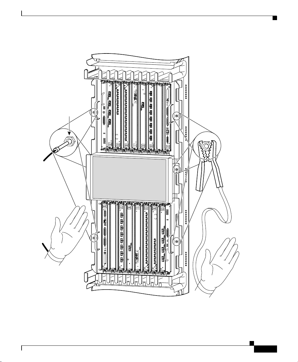
Preventing Electrostatic Discharge Damage
Many router components can be damaged by static electricity. Not exercising the
proper electrostatic discharge (ESD) precautions can result in intermittent or
complete component failures. To minimize the potential for ESD damage, always
use an ESD-preventive antistatic wrist strap (or ankle strap) and ensure that it
makes good skin contact.
Note Check the resistance value of the ESD-preventive strap periodically. The
measurement should be between 1 and 10 megohms.
Before you perform any of the procedures in this guide, attach an ESD-preventive
strap to your wrist and connect the leash to the chassis or to another grounded,
bare metal surface as shown in Figure 2-1.
Chapter 2 Preparing for Installation
2-4
Cisco XR 12416 and Cisco XR 12816 Router Chassis Installation Guide
OL-17440-01
Page 5
Chapter 2 Preparing for Installation
Figure 2-1 Connecting an ESD-Preventive Strap to the Router Chassis
DOWN
LOOP RA LA
DOWN
LOOP RA LA
CDHNT CD
CDHNT CD
TX
TX
0
0
RX
RX
0
TX
TX
1
1
RX
RX
A
C
T
IV
C
E
A
TX
R
TX
R
R
IE
X
R
P
2
K
2
T
RX
RX
TX
TX
ESD
connection
socket
O
O
O
O
O
O
O
O
O
O
O
O
O
O
O
O
O
O
O
O
O
O
O
O
O
O
O
O
O
O
O
O
O
O
O
O
O
O
O
O
O
O
O
O
O
O
O
O
O
O
O
O
O
O
O
O
O
O
O
O
O
O
O
O
O
O
O
O
O
O
O
O
O
O
O
O
O
O
O
O
O
O
O
O
O
O
O
O
O
O
O
O
O
O
O
O
O
1
3
A
C
3
TI
V
CRITICAL
RX
MAJOR
A
C
T
TX
I
V
C
MINOR
E
A
R
R
R
4
I
X
E
R
P
K
T
RX
TX
2
5
RX
ACO/LT
A
C
T
IV
C
E
A
R
R
R
I
X
E
R
P
K
T
ALARM
3
A
C
T
IV
C
E
A
R
R
R
IE
X
R
P
K
T
ENABLED
FAIL
ENABLED
FAIL
0
Q OC-3/STM-POS
CSC
1
6DS3–SMB P
0
1
SFC
ALARM
2
/
H
/
F
ROUTE PROCESSOR
RJ-45
MII
RX
TX
COLL
LINK
CONSOLE
X
U
A
RESET
SLOT-1
SLOT-0
EJECT
RX
TX
4
RX
TX
5
RX
TX
6
RX
TX
7
RX
TX
8
RX
TX
9
RX
TX
10
RX
TX
11
RX
12DS3–SMB P
/
H
/
F
FAST ETERNET
0
E
C
A
R
R
IE
R
X
R
P
K
T
A
C
T
IV
C
E
A
R
R
R
IE
X
C
R
E
L
L
OC-48/STM-16-SCPOS
OC-12/STM-4 ATM
FAST ETERNET
F
/
H
/
OC-12/STM-4 ATM
12DS3–SMB P
RX
OC-48/STM-16-SCPOS
11
TX
RX
10
TX
RX
9
TX
RX
8
TX
RX
7
TX
RX
6
TX
RX
5
L
L
E
R
C
X
IE
R
R
R
A
E
C
IV
T
C
A
TX
RX
4
TX
T
K
X P
R
IER
R
R
RX
A
C
E
0
IV
T
3
C
A
TX
RX
2
TX
RX
1
TX
RX
0
TX
CDHNT CD
LOOP RA LA
DOWN
EJECT
SLOT-0
SLOT-1
RESET
A
U
X
CONSOLE
LINK
COLL
TX
RX
MII
RJ-45
ROUTE PROCESSOR
F
/
H
/
2
ALARM
SFC
1
0
6DS3–SMB P
1
CSC
Q OC-3/STM-POS
0
FAIL
ENABLED
FAIL
ENABLED
T
K
P
R
E
X
I
R
R
R
A
E
C
IV
T
C
A
3
ALARM
T
K
P
R
E
X
I
R
R
R
A
E
C
IV
T
C
A
ACO/LT
RX
5
2
TX
RX
T
K
P
R
E
X
I
4
R
R
R
MINOR
A
E
C
IV
TX
T
C
MAJOR
A
CRITICAL
RX
3
1
TX
RX
T
K
2
P
R
E
X
I
R
R
R
TX
A
E
C
IV
T
C
A
RX
1
TX
0
RX
0
TX
CDHNT CD
LOOP RA LA
DOWN
Safety Guidelines
OL-17440-01
26208
Cisco XR 12416 and Cisco XR 12816 Router Chassis Installation Guide
2-5
Page 6
Safety Guidelines
Lifting Guidelines
A fully configured router can weigh as much as 275 pounds (lb)
(124.74 kilograms (kg)), while an empty chassis weighs 125 lb (56.7 kg). These
systems are not intended to be moved frequently. Before you install the router,
ensure that your site is properly prepared so you can avoid having to move the
router later to accommodate power sources and network connections.
Use the following lifting guidelines to avoid injury to yourself or damage to the
equipment:
• Do not lift equipment alone; have another person help you to lift heavy
• Ensure that your footing is solid; balance the weight of the object between
• Lift the equipment slowly; never move suddenly or twist your body as you
• Keep your back straight and lift with your legs, not your back. When bending
Chapter 2 Preparing for Installation
equipment.
your feet.
lift.
down to lift equipment, bend at the knees (not at the waist), to reduce the
strain on your lower back muscles.
Caution To prevent equipment damage, never attempt to lift or tilt the router chassis using
the handles on the blower module or on line cards. These handles do not support
the weight of the chassis.
Compliance and Safety Information
The Cisco XR 12416 router is designed to meet the regulatory compliance and
safety approval requirements. Refer to the Regulatory Compliance and Safety
Information for the Cisco 12000 Series Router if you require additional
compliance information (see “Obtaining Documentation and Submitting a
Service Request” section on page -xiv for site information).
Cisco XR 12416 and Cisco XR 12816 Router Chassis Installation Guide
2-6
OL-17440-01
Page 7
Chapter 2 Preparing for Installation
Laser Safety
Some line cards are equipped with ports that can emit hazardous laser radiation
from the aperture when there is no cable connected to the port. This invisible
radiation can cause eye injury if you stare into the port.
Site Requirement Guidelines
Warning
To avoid eye injury, never stare into open line card ports.
Site Requirement Guidelines
This section provides the following site requirement guidelines that you must
consider before installing the router:
• Rack-Mounting Guidelines, page 2-7
• Air Flow Guidelines, page 2-14
• Temperature and Humidity Guidelines, page 2-16
• Power Connection Guidelines, page 2-16
• NEBS Supplemental Unit Bonding and Grounding Guidelines, page 2-21
• Site Wiring Guidelines, page 2-23
Rack-Mounting Guidelines
The router can be mounted in most 2-post, 4-post, or telco-type 19-inch
equipment racks that comply with the Electronics Industries Association (EIA)
standard for equipment racks (EIA-310-D). The rack must have at least two posts
with mounting flanges to mount the router chassis. The distance between the
center lines of the mounting holes on the two mounting posts must be 18.31 inches
± 0.06 inch (46.50 cm ± 0.15 cm). The rack-mounting hardware included with the
router is suitable for most 19-inch equipment racks or telco-style frames.
Figure 2-2 shows examples of typical 2-post, 4-post, and telco-type equipment
racks.
OL-17440-01
Cisco XR 12416 and Cisco XR 12816 Router Chassis Installation Guide
2-7
Page 8
Site Requirement Guidelines
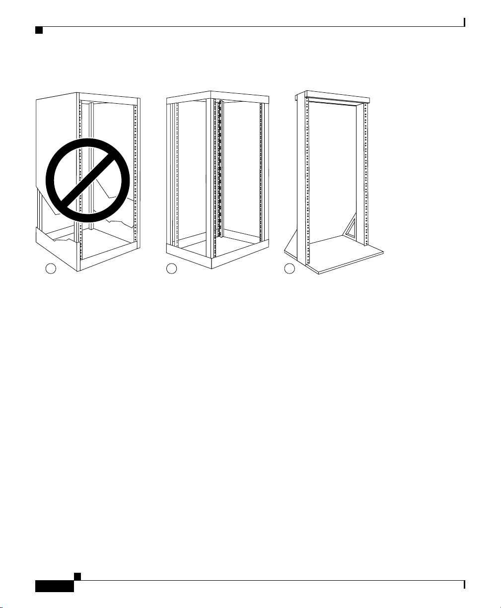
Figure 2-2 Equipment Rack Types
a b c
Chapter 2 Preparing for Installation
27959
Enclosed Rack
Open Rack
Cisco XR 12416 and Cisco XR 12816 Router Chassis Installation Guide
2-8
Figure 2-2a shows a free-standing, enclosed rack with two mounting posts in the
front. The router should not be installed in this type of enclosed rack, because the
router requires an unobstructed flow of cooling air to maintain acceptable
operating temperatures for its internal components. Installing the router in any
type of enclosed rack—even with the front and back doors removed—could
disrupt the air flow, trap heat next to the chassis, and cause an overtemperature
condition inside the router.
Figure 2-2b shows a free-standing, 4-post open rack with two mounting posts in
the front and two mounting posts in the back. The mounting posts in this type of
rack are often adjustable so that you can position the rack-mounted unit within the
depth of the rack rather than flush-mount with the front of the rack.
OL-17440-01
Page 9

Chapter 2 Preparing for Installation
Telco Rack
Figure 2-2c shows a telco-type rack. The telco-type rack is an open frame
consisting of two posts tied together by a cross-bar at the top and a floor stand at
the bottom.
This type of rack is usually secured to the floor and sometimes to an overhead
structure or wall for additional stability. The router chassis can be installed in the
telco-type rack either in a front-mounted position or a center-mounted position
(Figure 2-3).
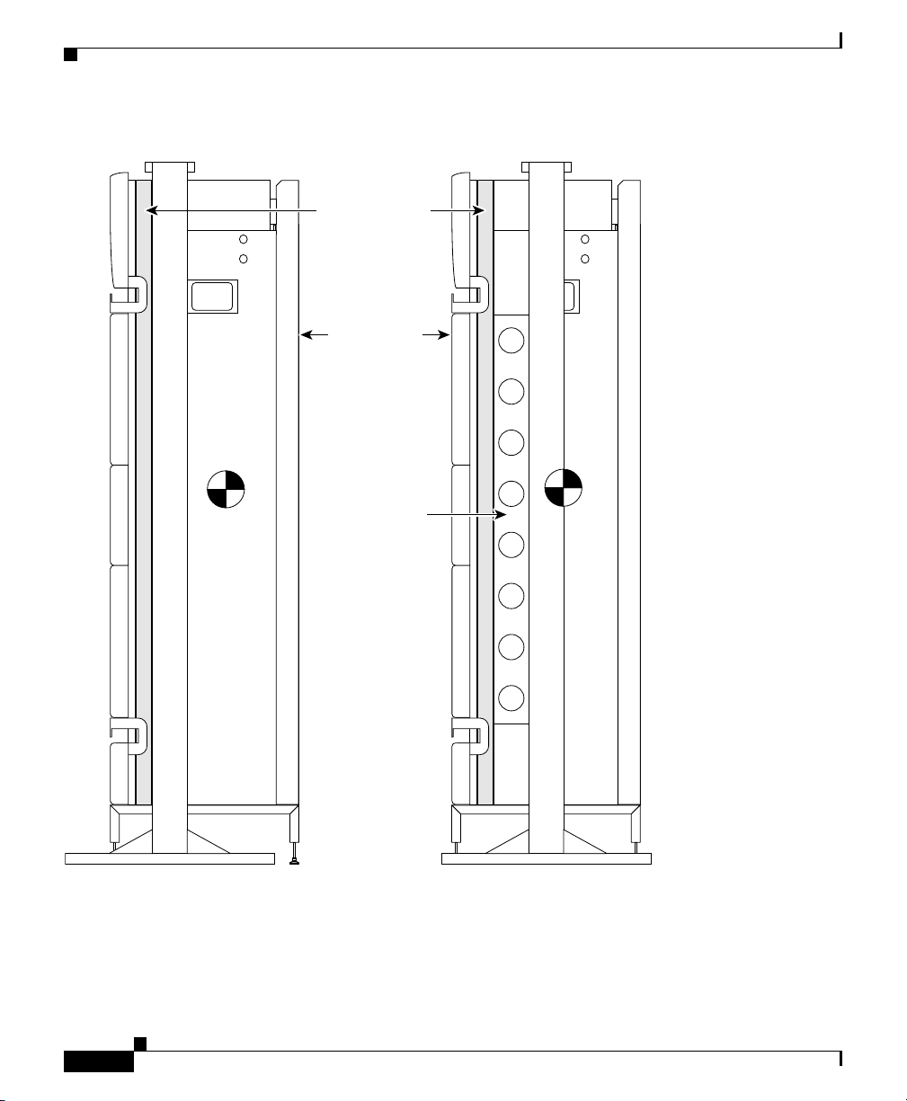
• In the front-mounted position, you secure the chassis rack-mounting brackets
• In the center-mounted position, you secure a set of optional center-mount
Site Requirement Guidelines
directly to the rack posts.
brackets to the rack posts. The chassis rack-mounting flanges are then
secured to the center-mount brackets. The center-mounted position moves the
center of gravity of the chassis closer to the vertical axis of the rack posts,
which adds to the stability of the rack installation.
OL-17440-01
Cisco XR 12416 and Cisco XR 12816 Router Chassis Installation Guide
2-9
Page 10
Chapter 2 Preparing for Installation
Site Requirement Guidelines
Figure 2-3 Front-Mounted and Center-Mounted Installation in a Telco Rack
Front-mount rail
Cisco 12016
chassis
Center-mount
bracket
Front-mounted chassis
in telco rack
Cisco XR 12416 and Cisco XR 12816 Router Chassis Installation Guide
2-10
Center-mounted chassis
27958
in telco rack
OL-17440-01
Page 11

Chapter 2 Preparing for Installation
Site Layout and Equipment Dimensions
To help maintain trouble-free operation, adhere to the following precautions when
planning your rack installation:
• Ensure the site of the rack includes provisions for source AC or DC power,
grounding, and network interface cables.
• Allow sufficient space to work around the rack during the installation. You
need:
–
At least 3 feet adjacent to the rack to move, align, and insert the chassis.
–
At least 2 feet in front of the power shelf to insert power entry modules.
• Maintain at least 24 inches (61 cm) of clearance in front of and behind the
chassis for maintenance after installation.
• To mount the router between two posts or rails, the usable aperture (the width
between the inner edges of the two mounting flanges) must be at least
17.7 inches (45.0 cm).
• When fully populated with cards, the router can weigh as much as 440 lb
(200 kg). Mount the router so that the bottom of the router chassis is no higher
than 10 inches (25.4 cm) from the floor to keep the center of gravity of the
rack as low as possible. To maintain equipment rack stability and to ensure
your safety, make sure you install any stabilizing devices provided before you
install the router.
• If you use a telco-style rack, the weight of the chassis is cantilevered off of
the two rack posts. Make sure that:
Site Requirement Guidelines
OL-17440-01
–
The weight of the router does not make the frame unstable.
–
The frame is bolted to the floor and is secured to the building structure
using either wall brackets or overhead brackets.
• When mounting the router in a telco-type rack or 4-post rack, be sure to use
all of the screws provided to secure the chassis to the rack posts.
• For theCisco XR 12416 router, the mounting rails on a 4-post rack must be
recessed no more than 1.5 inches for the front door to fully open and close
and to provide adequate room for cable routing.
Cisco XR 12416 and Cisco XR 12816 Router Chassis Installation Guide
2-11
Page 12

Site Requirement Guidelines
• Install the cable-management brackets included with the router to keep cables
• To avoid noise interference in network interface cables, do not route them
Chapter 2 Preparing for Installation
organized. Be sure to:
–
Use appropriate strain-relief methods to protect cables and equipment
connections.
–
Make sure that cables from other equipment installed in the rack do not
restrict access to the card cages.
directly across or along power cables.
2-12
Cisco XR 12416 and Cisco XR 12816 Router Chassis Installation Guide
OL-17440-01
Page 13

Chapter 2 Preparing for Installation
Figure 2-4 shows the footprint and outer dimensions of the of router chassis.
Figure 2-4 Router Chassis Footprint and Dimensions—Top View
17.963 in.
25.694 in.
Site Requirement Guidelines
17.3 in.
OL-17440-01
7.731 in.
18.950 in.
Cisco XR 12416 and Cisco XR 12816 Router Chassis Installation Guide
57090
2-13
Page 14

Site Requirement Guidelines
Air Flow Guidelines
Cool air is circulated through the router chassis by two blower modules. The
blower modules maintain acceptable operating temperatures for the internal
components by drawing in cool air through the air filter in front of the switch
fabric card cage (middle), and circulating the air through both card cages
(Figure 2-5).
Each power supply is also equipped with a fan that draws cooler air into the front
of the power supply and forces warmer air out of the back of the chassis.
When selecting a site to install the router, observe the following guidelines:
• Dust free area—The site should be as dust free as possible. Dusty
environments can clog the air filter or power supply intake vents, reducing the
cooling air flow through the router. Clogged filters and vents can cause an
overtemperature condition in the router.
• Unrestricted air flow—Allow sufficient air flow by maintaining a minimum
of 6 inches (15.24 cm) of clearance at both the inlet and exhaust openings on
the chassis and the power modules. If the air flow is blocked or restricted, or
if the inlet air is too warm, an overtemperature condition can occur within the
router. Under extreme conditions, the environmental monitoring system will
power off the router to protect the components.
Chapter 2 Preparing for Installation
2-14
Cisco XR 12416 and Cisco XR 12816 Router Chassis Installation Guide
OL-17440-01
Page 15

Chapter 2 Preparing for Installation
Figure 2-5 Air Flow Path through the Router - Side View
Site Requirement Guidelines
Power supply shelf
Top blower module
Air filter
Room air
Air exhaust
(Plenum)
Upper card cage
Middle card cage
Lower card cage
(Plenum)
OL-17440-01
Bottom blower module
Front Rear
Cisco XR 12416 and Cisco XR 12816 Router Chassis Installation Guide
Air exhaust
26204
2-15
Page 16

Site Requirement Guidelines
Temperature and Humidity Guidelines
The operating and nonoperating environmental site requirements are listed in
Table A-4 on page A-4. The router normally operates within the ranges listed in
the table, however, if a temperature measurement is approaching a minimum or
maximum parameter it indicates a potential problem. Maintain normal operation
by anticipating and correcting environmental anomalies before they approach
critical values by properly planning and preparing your site before you install the
router.
Power Connection Guidelines
You can configure the router with either an AC-input or DC-input power
subsystem, so the site power source requirements differ depending on the power
subsystem in your router. Ensure all power connection wiring conforms to the
rules and regulations in the National Electrical Code (NEC), as well as local
codes.
Chapter 2 Preparing for Installation
2-16
Caution Proper grounding is necessary to avoid damage from lightning and power surges.
See the “Router Bonding and Grounding Receptacles—Top Rear” section on
page 2-22 for grounding requirements.
Cisco XR 12416 and Cisco XR 12816 Router Chassis Installation Guide
OL-17440-01
Page 17

Chapter 2 Preparing for Installation
AC-Powered Routers
AC PEMs operate in the nominal range of 200 VAC to 240 VAC and require a
minimum service of:
• 20 A for operation in North America
• 16 A for international operation
• 13 A for operation in the UK
Each of the AC power inputs requires separate dedicated branch circuit. For a list
of the nominal and acceptable value ranges for source AC power, refer to
Table A-2 on page A-3.
Figure 2-6 shows different styles of AC power cords used to connect to the local
AC power source that are available for North America and various locales.
Figure 2-6 AC Power Cord Plugs and Appliance Coupler
Site Requirement Guidelines
North America
Rewirable twist-lock plug
NEMA L6-20P (20A)
Italy
1/3/16 plug
CEI 23-16 (16A)
OL-17440-01
Australia, New Zealand
SAA/3 plug
AS/NZZS 3112-1993 (15A)
United Kingdom
BS89/13
BS 1363/A
(13A; replaceable fuse)
Cisco XR 12416 and Cisco XR 12816 Router Chassis Installation Guide
Europe, Argentine, Brazil
VIIG plug
CEE (7) VII (16A)
Appliance coupler
C19W coupler
Hot EN60320/C19 (20A)
26044
2-17
Page 18

Site Requirement Guidelines
Table 2-1 lists power cord options. All AC-input power supply power cords
measure 14 feet (4.3 m).
Table 2-1 AC Power Cord International Options
Label Description Part Number
North America 20 A, 250 VAC CAB-GSR16-US=
Australia, New Zealand 15 A, 250 VAC CAB-GSR16-AU=
Europe, Argentina, Brazil 16 A, 250 VAC CAB-GSR16-EU=
Italy 16 A, 250 VAC CAB-GSR16-IT=
United Kingdom 13 A, 250 VAC
DC-Powered Routers
Connections to DC PEMs are rated at 60 amps maximum. A dedicated,
commensurately rated DC power source is required for each PEM connection.
For DC power cables, we recommend that you use a commensurately rated,
high-strand-count copper wire cable. Connection to the DC power shelf requires
one earth ground cable and two cable leads; a source DC (–) and source DC return
(+) for each PEM. The length of the cables depends on your router location from
the source power.
Chapter 2 Preparing for Installation
CAB-GSR16-UK=
(13 A replaceable fuse)
2-18
Note DC power cables are not available from Cisco, but are available from any
commercial cable vendor.
Cisco XR 12416 and Cisco XR 12816 Router Chassis Installation Guide
OL-17440-01
Page 19

Chapter 2 Preparing for Installation
You must terminate DC power cables using cable lugs at the power shelf end.
Ensure the lugs are dual-hole and that they are able to fit over M6 terminal studs
at 0.625-inch (15.88-mm) centers (for example, Panduit Part Number
LCD8-14A-L or equivalent).
Figure 2-7 shows the type of lug required for the DC-input cable connections.
Figure 2-7 DC Power Cable Lug
End View
Site Requirement Guidelines
All measurements in inches
2.24
0.48
Ø 0.267
2 holes
Crimp area
0.25 0.370.63
0.08
Figure 2-8 shows a source DC power distribution scheme for a DC-input power
shelf.
It shows two power cables attached to the DC-input power lugs for power shelf
bay B1 (far right bay of the DC-input power shelf when looking at the back panel).
The color coding of the source DC power cable leads depends on the color coding
of the site DC power source. Typically, green or green and yellow indicate that the
cable is a ground cable. Because there is no color code standard for the source DC
wiring, be sure that the power cables are connected to the DC-input power shelf
terminal studs using the proper positive (+) and negative (–) polarity.
• In some cases, the source DC cable leads might have a positive (+) or a
negative (–) label. This is a relatively safe indication of the polarity, but you
must verify the polarity by measuring the voltage between the DC cable leads.
When making the measurement, the positive (+) lead and the negative (–) lead
must always match the (+) and (–) labels on the power shelf.
• A green (or green and yellow) cable typically indicate that it is a ground
cable.
25527
OL-17440-01
Cisco XR 12416 and Cisco XR 12816 Router Chassis Installation Guide
2-19
Page 20

Chapter 2 Preparing for Installation
Site Requirement Guidelines
Figure 2-8 Typical Source DC Power Cabling Scheme for Power Shelf Bay B1
CO ground
Central
office
RectifiersAC
primary &
secondary
DC power
distribution
Plant
controls
Battery plant
Batteries
Ground
window
Central office
ground
+
+
–
–
Ground
Ground
2-20
27963
Cisco XR 12416 and Cisco XR 12816 Router Chassis Installation Guide
OL-17440-01
Page 21

Chapter 2 Preparing for Installation
Site Requirement Guidelines
Caution DC PEMs contains circuitry to trip the breaker on the PEM if the PEM detects a
reverse polarity condition. No damage should occur from reverse polarity, but you
should correct a reverse polarity condition immediately.
For a list of the nominal and acceptable value ranges for source DC power, refer
to Table A-3 on page A-4.
NEBS Supplemental Unit Bonding and Grounding Guidelines
Although the router chassis requires a safety earth ground connection as part of
the power cabling to the power shelf, we also recommend that you connect the
central office ground system or interior equipment grounding system to the
supplemental bonding and grounding connections.
Supplemental connections are located at the top of the power interface panel on
the back of the chassis (Figure 2-9), and near the lower corners of the switch
fabric card cage on the front flanges of the chassis (Figure 2-10). The DC return
of this system should remain isolated from the system frame and chassis (DC-I).
This grounding points are also referred to as the network equipment building
system (NEBS) bonding and grounding connections.
OL-17440-01
Note These bonding and grounding connections satisfy the Telcordia NEBS
requirements for supplemental bonding and grounding connections. If you are not
installing the router in a NEBS environment, you can choose to bypass these
guidelines and rely on the safety earth ground connections to the AC and DC
power shelves.
Cisco XR 12416 and Cisco XR 12816 Router Chassis Installation Guide
2-21
Page 22

Site Requirement Guidelines
Figure 2-9 Router Bonding and Grounding Receptacles—Top Rear
Supplemental
bonding and
grounding
receptacle
Figure 2-10 Router Bonding and Grounding Receptacles—Front
Q OC-3/STM-POS
6DS3–SMB P
/
H
/
F
RX
TX
11
RX
12DS3–SMB P
/
H
/
F
OC-48/STM-16-SCPOS
OC-12/STM-4 ATM
FAST ETERNET
ROUTE PROCESSOR
EN
ABLED
FAIL
0
CSC
1
0
1
SFC
ALARM
2
Chapter 2 Preparing for Installation
29183
NEBS
supplemental
earth ground
receptacle
Air filter door
2-22
28022
Cisco XR 12416 and Cisco XR 12816 Router Chassis Installation Guide
OL-17440-01
Page 23

Chapter 2 Preparing for Installation
To ensure a satisfactory supplemental ground connection to the router, use the
following parts:
Note These parts are not available from Cisco, but are available from commercial
vendors.
• Two grounding lugs, which have two M6 bolt holes with 0.625 to 0.75-inch
(15.86 to 19.05-mm) spacing between them, and a wire receptacle large
enough to accept a 6-AWG or larger, multistrand copper wire. This lug is
similar to those used for the DC-input power supply leads (see Figure 2-7).
• Two M6 hex-head nuts and locking washers (nickel-plated brass is ideal).
• Two grounding wires. Although we recommend at least 6-AWG multistrand
copper wire, the wire diameter and length depend on your router location and
site environment.
Site Wiring Guidelines
Site Requirement Guidelines
OL-17440-01
When planning the location of the router, consider distance limitations for
signaling, electromagnetic interference (EMI), and connector compatibility. If the
wiring is run for any significant distance in an electromagnetic field, interference
can occur between the field and the signals on the wires. Poor wiring can cause:
• Radio interference emanating from the wires.
• Strong EMI, especially when caused by lightning or radio transmitters. EMI
can destroy the signal drivers and receivers in the router, and can even create
an electrical hazard by conducting power surges through lines and into
equipment.
Note To predict and remedy strong EMI, you may need to consult with experts
in radio frequency interference (RFI).
Cisco XR 12416 and Cisco XR 12816 Router Chassis Installation Guide
2-23
Page 24

PRP Port Connection Guidelines
Site wiring is unlikely to emit radio interference if you use twisted-pair cable with
a good distribution of grounding conductors. Use a high-quality twisted-pair cable
with one ground conductor for each data signal, when applicable.
Give special consideration to the effect of a lightning strike in your vicinity,
especially if the wiring exceeds the recommended distances, or if it passes
between buildings. The electromagnetic pulse (EMP) caused by lightning or other
high-energy phenomena can easily induce enough energy into unshielded
conductors to destroy electronic devices. If you have experienced EMP problems
in the past, you may want to consult experts in electrical surge suppression and
shielding.
Most data centers cannot resolve the infrequent but potentially catastrophic
problems without pulse meters and other special equipment. In addition, these
problems can take a great deal of time to identify and resolve. We recommend that
you take the necessary precautions to avoid these problems by providing a
properly grounded and shielded environment, with special attention to issues of
electrical surge suppression.
PRP Port Connection Guidelines
Chapter 2 Preparing for Installation
This section contains detailed cabling and signal information for all interface and
port connections to the PRP. It also provides information for Ethernet routing and
equipment.
Caution Ports labeled Ethernet, 10BASE-T, Token Ring, Console, and AUX are safety
extra-low voltage (SELV) circuits. Only connect SELV circuits to other
SELV circuits.
PRP Auxiliary and Console Port Connection Guidelines
The PRP has two RJ-45 connection ports:
• Auxiliary port— DTE RJ-45 interface for connecting a modem or other
DCE device (such as a CSU/DSU or another router) to the PRP.
• Console port—DCE RJ-45 interface for connecting a data terminal device to
the router, which you need to perform the initial configuration of the router.
Cisco XR 12416 and Cisco XR 12816 Router Chassis Installation Guide
2-24
OL-17440-01
Page 25
Chapter 2 Preparing for Installation
Note The auxiliary and console ports are asynchronous serial ports. Ensure that
devices connected to these ports are capable of asynchronous
transmission.
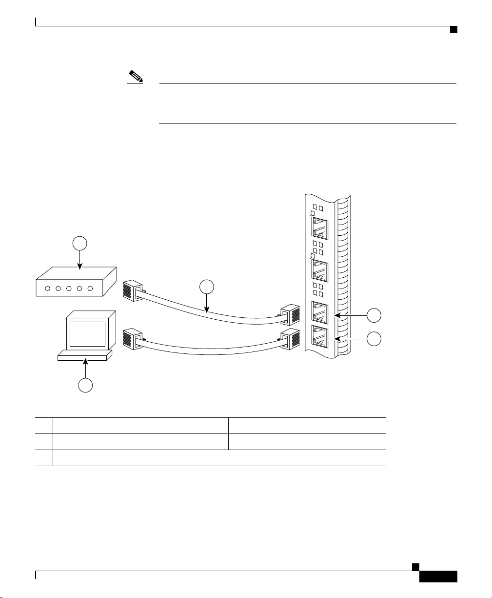
Figure 2-11 shows the auxiliary and console port connections from the PRP to the
associated devices.
Figure 2-11 PRP Auxiliary and Console Port Connections
1
3
PRP Port Connection Guidelines
S
L
S
O
L
O
T
PRIMARY
-0
T
-1
LIN
E
K
N
T
X
R
X
PRIMARY
ETH 1ETH 0 AUX
LIN
E
K
N
T
X
R
X
2
1 Modem 4 Auxiliary port
2 Console terminal 5 Console port
3 RJ-45 cables
Cisco XR 12416 and Cisco XR 12816 Router Chassis Installation Guide
OL-17440-01
4
CONSOLE
5
70692
2-25
Page 26

PRP Port Connection Guidelines
PRP Auxiliary Port Signals
The PRP auxiliary port is a DTE, RJ-45 interface for connecting a modem or other
DCE device (such as a CSU/DSU or another router) to the PRP. The auxiliary port
supports hardware flow control and modem control.
Table 2-2 lists the signals used on the auxiliary port.
Table 2-2 PRP Auxiliary Port Signals
Auxiliary Port Pin Signal Input/Output Description
1 RTS Output Request to send
2 DTR Output Data terminal ready
3 TxD Output Transmit data
4 GND — Signal ground
5 GND — Signal ground
6 RxD Input Receive data
7 DSR Input Data set ready
8 CTS Input Clear to send
Chapter 2 Preparing for Installation
2-26
Cisco XR 12416 and Cisco XR 12816 Router Chassis Installation Guide
OL-17440-01
Page 27

Chapter 2 Preparing for Installation
PRP Console Port Signals
The PRP console port is a DCE RJ-45 interface for connecting a terminal to the
router. The console port does not support modem control or hardware flow control
and requires a roll-over RJ-45 cable.
Before connecting a terminal to the console port, check the terminal setting for
the data transmission rate, in bits per second (bps). The terminal transmission rate
setting must match the default rate of the PRP console port, which is 9600 bps.
Set the terminal to these operational values: 9600 bps, 8 data bits, no parity, 2 stop
bits (9600 8N2).
Table 2-3 lists the signals used on the console port.
Table 2-3 PRP Console Port Signals (with RJ45 roll-over cable)
Console Port Pin Signal Input/Output Description
1
1
2 DTR Output Data terminal ready
3 TxD Output Transmit data
4 GND — Signal ground
5 GND — Signal ground
6 RxD Input Receive data
7 DSR Input Data set ready
1
8
1. These pins are not connected.
PRP Port Connection Guidelines
—— —
—— —
OL-17440-01
Cisco XR 12416 and Cisco XR 12816 Router Chassis Installation Guide
2-27
Page 28

PRP Port Connection Guidelines
PRP Ethernet Connections
The PRP has two RJ-45 MDI Ethernet ports; ETH0 and ETH1 (Figure 2-12).
Figure 2-12 PRP Ethernet Connections
Chapter 2 Preparing for Installation
ETH 1ETH 0
SLOT-1
SLOT-0
PRIMARY
EN
LINK
RX
TX
PRIMARY
EN
LINK
RX
TX
70693
These connections support IEEE 802.3 and IEEE 802.3u interfaces compliant
with 10BASE-T and 100BASE-TX standards. The transmission speed of the
Ethernet ports is autosensing by default and is user configurable.
The PRP Ethernet port does not provide external routing functions. Its primary
roles are to act as a Telnet port into the router, and to boot or access Cisco IOS XR
software images over a network to which the PRP Ethernet port is directly
connected.
Caution Cisco Express Forwarding (CEF) functions on these ports are switched off by
default for security reasons. We strongly caution you to consider the security
implications of switching on CEF routing functions on these ports.
2-28
Cisco XR 12416 and Cisco XR 12816 Router Chassis Installation Guide
OL-17440-01
Page 29

Chapter 2 Preparing for Installation
Figure 2-13 shows:
• You cannot access Network 2.0.0.0 from Ethernet port (E0) on the PRP in
Router A. You can only access Host A, Host B, and Router C, which are in
Network 1.0.0.0 (see dotted-line arrows).
• To access Network 2.0.0.0 from Router A, you must use an interface port on
one of the line cards (a POS line card in this example) in Router A. Data from
Router A is routed through Router B and Router C, to reach Network 2.0.0.0
(see solid-line arrows).
Figure 2-13 Using the Ethernet Port on the PRP
PRP Port Connection Guidelines
Router A
(Cisco 12000
series router)
POS
Router B
(Cisco 7500
series router)
EO
EO
Network 1.0.0.0
Host A
Host B
Router C
(Cisco 7500
series router)
Network 2.0.0.0
Host A
26196
OL-17440-01
Cisco XR 12416 and Cisco XR 12816 Router Chassis Installation Guide
2-29
Page 30

PRP Port Connection Guidelines
PRP RJ-45 Ethernet Connections
The RJ-45 Ethernet connection does not require an external transceiver.
Figure 2-14 shows the pin orientation of the RJ-45 Ethernet port and the modular
cable plug it accepts.
Figure 2-14 RJ-45 Receptacle and Plug
8 7 6 5 4 3 2 1
RJ-45 connector
Table 2-4 lists the RJ-45 pin signals used on the connector.
Table 2-4 PRP RJ-45 Ethernet Receptacle Pinout
Ethernet Port Pin Signal Description
1 TxD+ Transmit data +
2 TxD– Transmit data –
3 RxD+ Receive data +
4 Termination network No connection
5 Termination network No connection
6 RxD– Receive data –
7 Termination network No connection
8 Termination network No connection
Chapter 2 Preparing for Installation
210222
2-30
Cisco XR 12416 and Cisco XR 12816 Router Chassis Installation Guide
OL-17440-01
Page 31

Chapter 2 Preparing for Installation
When connecting the RJ-45 port to a hub or repeater, use the straight-through
cable pinout shown in Figure 2-15.
Figure 2-15 Straight-Through Cable Pinout to Hub or Repeater
1 TxD+
2 TxD–
PRP Port Connection Guidelines
MDI-X wiringMDI wiring
1 RxD+
2 RxD–
3 RxD+
6 RxD–
3 TxD+
6 TxD–
H11007
When connecting two PRPs back-to-back, use the crossover cable pinout shown
in Figure 2-16.
Figure 2-16 Crossover Cable Pinout Between PRPs
PRP
1 TxD+
2 TxD–
3 RxD+
6 RxD–
PRP
1 TxD+
2 TxD–
3 RxD+
6 RxD–
75431
OL-17440-01
Cisco XR 12416 and Cisco XR 12816 Router Chassis Installation Guide
2-31
Page 32

PRP Port Connection Guidelines
Table 2-5 lists the cabling specifications for 100-Mbps transmission over
unshielded twisted-pair (UTP) cables.
Note The transmission speed of the Ethernet ports is autosensing by default and is user
configurable.
Table 2-5 Specifications and Connection Limits for 100-Mbps
Parameter RJ-45
Cable specification Category 5
Cable length (max) —
Segment length (max) 328 feet (100 m) for 100BASE-TX
Network length (max) 656 feet (200 m)
1. EIA/TIA-568 or EIA-TIA-568 TSB-36 compliant. Not supplied by Cisco.
2. AWG = American Wire Gauge. This gauge is specified by the EIA/TIA-568 standard.
3. Specifically, the length between any two stations on a repeated segment.
Transmission
Chapter 2 Preparing for Installation
1
UTP, 22 to 24 AWG
3
with 1 repeater
2
2-32
Table 2-6 lists IEEE 802.3u physical characteristics for 100BASE-TX.
Table 2-6 IEEE 802.3u Physical Characteristics
Parameter 100BASE-TX
Data rate (Mbps) 100
Signaling method Baseband
Maximum segment length 100 m between DTE and repeaters
Media Category 5 UTP
Topology Star/Hub
Cisco XR 12416 and Cisco XR 12816 Router Chassis Installation Guide
OL-17440-01
Page 33

Chapter 2 Preparing for Installation
Alarm Card Connection Guidelines
The router is equipped with two alarm cards:
• One alarm card occupies the dedicated far left slot in the upper card cage
• The second alarm card occupies the dedicated far right slot in the lower card
cage
Each alarm card has one 25-pin D-subconnector (ALARM) on the front panel that
connects the router to an external site alarm maintenance system (Figure 2-17).
When a critical, major, or minor alarm is generated, it energizes the alarm relays
on the alarm card to activate the external site alarm.
Figure 2-17 Alarm Card Connector Location
Alarm Card Connection Guidelines
FAIL
ENABLED
CSC
FAIL
0
ENABLED
SFC
1
0
1
Critical, major, and
Handle
CRITICAL
MAJOR
minor alarm LEDs
MAJOR
CRITICAL
MINOR
MINOR
ACO/LT
Audio alarm
cutoff switch
Pin 25
ALARM
Pin 1
CSC
SFC
FAIL
ENABLED
FAIL
ENABLED
2
1
0
0
1
ALARM
Clock and scheduler card
and switch fabric card LEDs
The alarm relay contacts on the alarm card consist of standard common, normally
open, and normally closed relay contacts that are wired to the pins on the
connectors.
Caution Only safety extra-low voltage (SELV) circuits can be connected to the alarm
connector. Maximum rating for the alarm circuit is 2 A, 50 VA.
2
26867
OL-17440-01
Cisco XR 12416 and Cisco XR 12816 Router Chassis Installation Guide
2-33
Page 34

Alarm Card Connection Guidelines
Note To comply with the intrabuilding lightning surge requirements of
GR-1089-CORE, Issue II, Revision 01, February 1999, you must use a shielded
cable when connecting to the external alarm ports on the alarm card. The shielded
cable is terminated by shielded connectors on both ends, with the cable shield
material tied to both connectors.
Table 2-7 lists the pin-to-signal correspondence between the cable connector pins
and the alarm card relay contacts.
Table 2-7 Alarm Connector Pinout
Pin Group Common Normally Open Normally Closed
Critical audible alarm 2 1 14
Major audible alarm 16 3 15
Minor audible alarm 5 4 17
Critical visual alarm 19 6 18
Major visual alarm 8 7 20
Minor visual alarm 22 9 21
Alarm input 13 25 —
Chapter 2 Preparing for Installation
2-34
Cisco XR 12416 and Cisco XR 12816 Router Chassis Installation Guide
OL-17440-01
 Loading...