

Page 1
CHA PTER
5
Maintaining the Router
The Cisco XR 12416 router is equipped as ordered and is ready for installation
and startup when it is shipped. As your networking requiremen ts change, you may
need to upgrade the system by adding or changing components. This chapter
describes how to maintain router components.
Procedures for maintaining the router are described in the following sections:
• Powering Off the Router, page 5-2
• Removing and Installing Front Doors, page 5-3
• Cleaning or Replacing the Chassis Air Filter, page 5-7
• Removing and Replacing Blower Modules, page 5-10
• Removing and Replacing AC and DC Power Subsystem Components,
page 5-14
• Removing and Replacing the Standard AC-Input Power Shelf, page 5-19
• Removing and Replacing the Optional 2-Level AC-Input Power Shelf,
page 5-24
OL-13833-01
• Upgrading to the Optional AC Power Shelf, page 5-30
• Removing and Replacing a DC PEM, page 5-31
• Removing and Replacing the DC Power Shelf, page 5-37
• Removing and Replacing Cards from the Chassis, page 5-46
• Removing and Installing a Chassis, page 5-53
• Removing and Replacing a Power Bus Board Fuse, page 5-61
Cisco XR 12416 Router Installation Guide
5-1
Page 2
Powering Off the Router
Prerequisites and Preparation
Before you perform any of the procedures in this chapter, be sure that you:
• Review the “Safety Guidelines” section on page 2-2.
• Read the safety and ESD-prevention guidelines described in the “Preventing
Electrostatic Discharge Damage” section on page 2-4.
• Ensure that you have all of the necessary tools and equipment before
beginning the procedure.
• Have access to the following documents during the installation:
–
Regulatory Compliance and Safety Information for Cisco 12000 Series
Routers publication that shipped with the router.
Powering Off the Router
Most field-replaceable units (FRUs) can be remov ed and replaced with the power
on and the system operating. This is kno wn as online inserti on and remova l (OIR).
Power supplies, line cards, the RP, CSCs, SFCs, and alarm cards all support OIR.
Unless otherwise noted, the maintenance tasks described in this chapter can be
performed while the router remains powered on.
Chapter 5 Maintaining the Router
5-2
In some cases it may be necessary to power off the router, for ex ample, to upgrade
power supplies or to replace a power shelf. Use the followi ng procedure to po w er
off the router.
Step 1 Set the power switch on each power supply to the off (0) position.
Step 2 Power off all circuit breakers for the source power lines connected to the power
supplies.
Step 3 Verify that the PWR OK indicator on each power supply is off.
Step 4 Verify that the OK indicator on each blower module is off.
Cisco XR 12416 Router Installation Guide
OL-13833-01
Page 3
Chapter 5 Maintaining the Router
Removing and Installing Front Doors
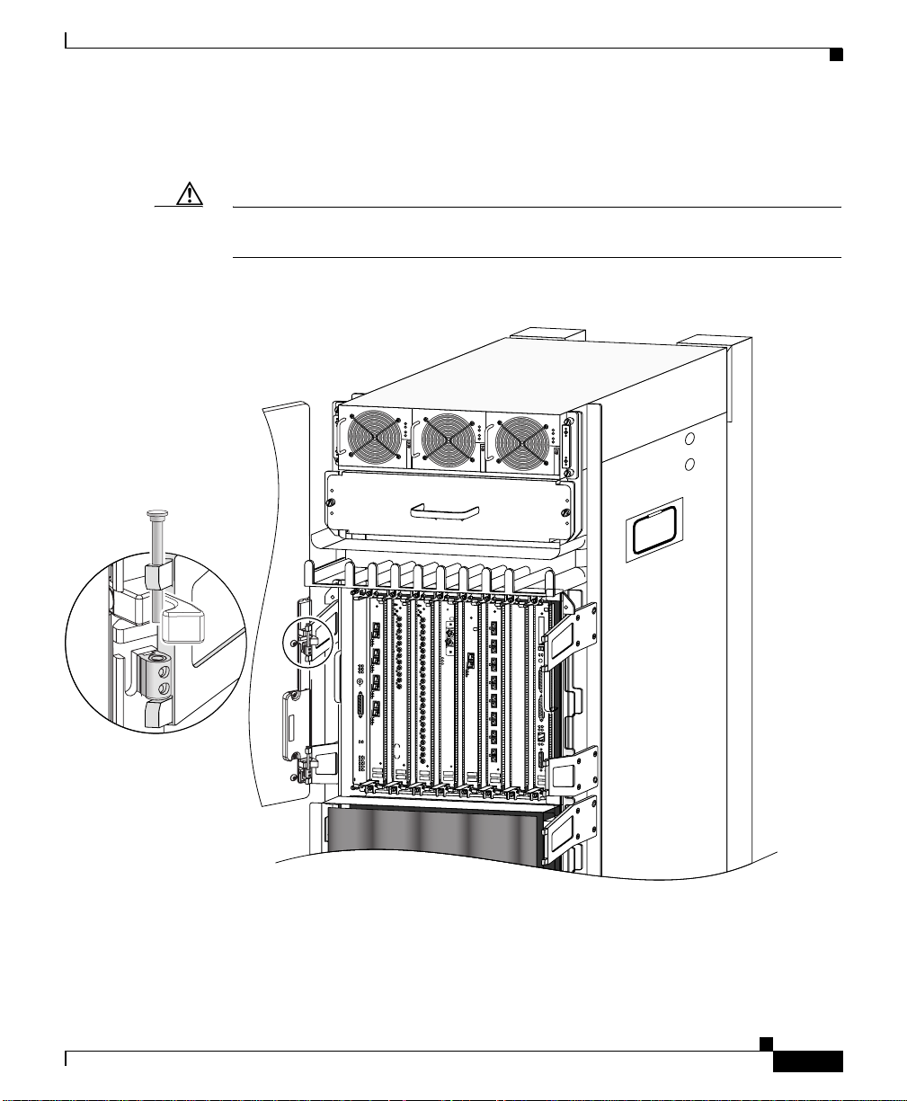
The router ships with the door hinges mounted on the left side of the chassis so
that they open from right-to-left. This section describes how to change the front
doors to open from left-to-right by installing the hinges on the opposite side.
Use the following procedure to change the location of the hinges.
Note The illustrations in this procedure show the top front door, but the procedure is
the same for either the top or bottom door.
Removing and Installing Front Doors
OL-13833-01
Cisco XR 12416 Router Installation Guide
5-3
Page 4
Removing and Installing Front Doors
149541
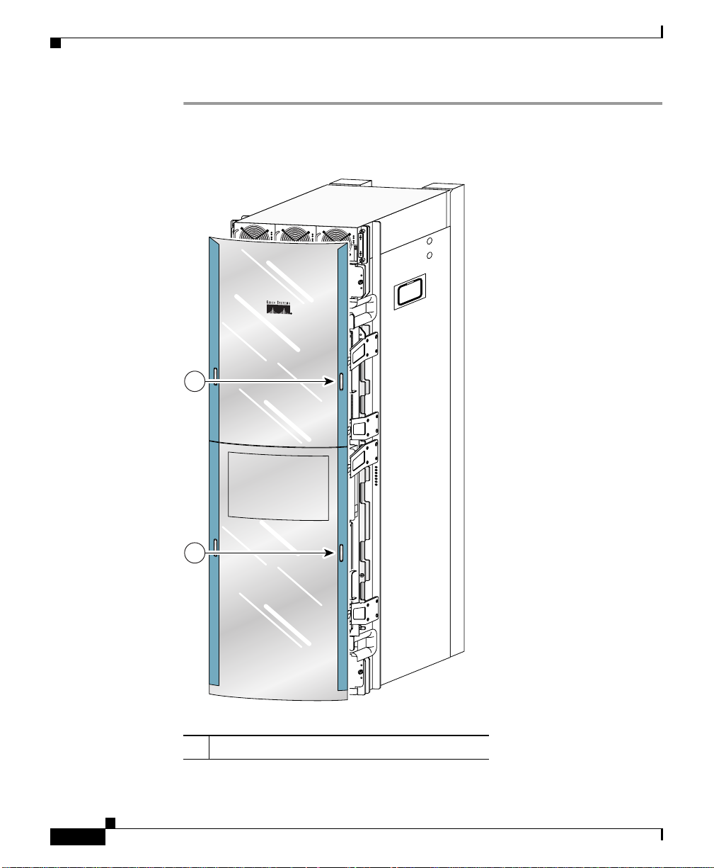
Step 1 Open the top front door by pressing the right latch button (Figure 5-1).
Figure 5-1 Opening the Front Door
1
Chapter 5 Maintaining the Router
P
WR
OK
PWR OK
FAU
LT
TEMP
I LIM
DOWN
LOOP RA LA
DOWN
LOOP RA LA
CDHNT CD
CDHNT CD
TX
TX
0
0
RX
RX
0
TX
TX
1
1
RX
RX
ACTIVE
CARRIER
TX
TX
RX PKT
2
2
RX
RX
TX
TX
1
3
ACTIVE
3
CRITICAL
MAJOR
ACTIVE
CARRIER
MINOR
RX PKT
2
ACO/LT
ACTIVE
CARRIER
RX PKT
ALARM
3
ACTIVE
CARRIER
RX PKT
ENABLED
FAIL
ENABLED
FAIL
0
Q OC-3/STM-POS
CSC
1
0
1
SFC
ALARM
2
0
CARRIER
RX
RX
RX PKT
TX
TX
ACTIVE
4
4
CARRIER
RX
RX CELL
RX
TX
TX
5
5
RX
RX
TX
6
RX
TX
7
RX
TX
8
RX
TX
9
RX
TX
10
RX
TX
11
OC-48/STM-16-SCPOS
RX
12DS3–SMB P
6DS3–SMB P
OC-12/STM-4 ATM
/
/
H
H
/
/
F
F
PWR O
FA
U
TEMP
I
LIM
K
LT
FAULT
TEMP
I LIM
EJECT
SLOT-0
SLOT-1
RESET
AUX
CONSOLE
LINK
COLL
TX
RX
MII
RJ-45
FAST ETERNET
ROUTE PROCESSOR
5-4
ROUTE PROCESSOR
FAST ETERNET
OC-12/STM-4 ATM
RJ-45
MII
RX
TX
COLL
1
LINK
CONSOLE
AUX
RESET
SLOT-1
SLOT-0
EJECT
OC-48/STM-16-SCPOS
RX CELL
CARRIER
ACTIVE
RX PKT
CARRIER
0
ACTIVE
1 Front door latches
Cisco XR 12416 Router Installation Guide
F
F
/
/
H
H
/
/
2
ALARM
SFC
1
0
6DS3–SMB P
12DS3–SMB P
1
RX
CSC
Q OC-3/STM-POS
0
11
TX
FAIL
ENABLED
RX
10
TX
FAIL
RX
ENABLED
9
TX
RX
RX PKT
8
CARRIER
ACTIVE
TX
RX
3
7
TX
ALARM
RX
RX PKT
6
CARRIER
TX
ACTIVE
RX
ACO/LT
RX
5
5
2
TX
TX
RX
RX
4
4
RX PKT
MINOR
TX
CARRIER
TX
MAJOR
ACTIVE
RX
CRITICAL
RX
3
3
1
TX
TX
RX
RX
2
2
RX PKT
TX
TX
CARRIER
ACTIVE
RX
RX
1
1
TX
TX
0
RX
RX
0
0
TX
TX
CDHNT CD
CDHNT CD
LOOP RA LA
DOWN
LOOP RA LA
DOWN
OL-13833-01
Page 5
Chapter 5 Maintaining the Router
Step 2 Remove the front door by lifting the (top and bottom) hinge pins to free the door
from the chassis (Figure 5-2).
Caution Make sure you are holding the front door securely so it does not drop when you
release it from the chassis.
Figure 5-2 Removing or Installing Hinge Pins
Removing and Installing Front Doors
PWR OK
FAULT
TEMP
I LIM
DOWN
LOOP RA LA
DOWN
LOOP RA LA
CDHNT CD
CDHNT CD
TX
TX
0
0
RX
RX
0
TX
TX
1
1
RX
RX
ACTIVE
CARRIER
TX
TX
RX PKT
2
2
RX
RX
TX
TX
1
3
CRITICAL
MAJOR
MINOR
ACO/LT
ALARM
ENABLED
FAIL
ENABLED
FAIL
0
1
0
1
ALARM
2
3
RX
RX
ACTIVE
TX
CARRIER
TX
RX PKT
4
4
RX
RX
TX
TX
2
5
5
RX
RX
ACTIVE
TX
CARRIER
6
RX PKT
RX
TX
7
3
RX
TX
ACTIVE
CARRIER
8
RX PKT
RX
TX
9
RX
TX
10
RX
TX
11
Q OC-3/STM-POS
CSC
RX
12DS3–SMB P
6DS3–SMB P
SFC
/
/
H
H
/
/
F
F
ACTIVE
CARRIER
RX PKT
OC-48/STM-16-SCPOS
PWR OK
FAULT
TEMP
I LIM
0
ACTIVE
CARRIER
RX CELL
OC-12/STM-4 ATM
FAST ETERNET
PWR OK
FAULT
TEMP
I LIM
EJECT
SLOT-0
SLOT-1
RESET
AUX
CONSOLE
LINK
COLL
TX
RX
MII
RJ-45
ROUTE PROCESSOR
Reinstall the hinge pins into the chassis hinge brackets
149542
OL-13833-01
Cisco XR 12416 Router Installation Guide
5-5
Page 6
Removing and Installing Front Doors
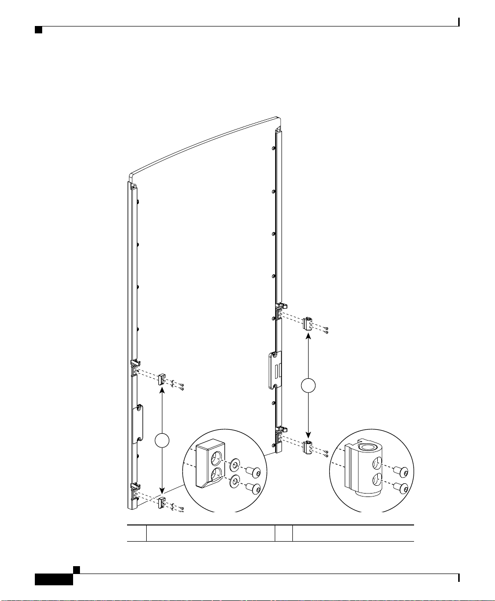
Step 3 Remove the bumpers and pivot blocks from the door as shown in Figure 5-3.
Figure 5-3 Removing the Bumpers and Pivot Blocks
Chapter 5 Maintaining the Router
5-6
2
1
49540
1 Bumpers 2 Pivot blocks
Cisco XR 12416 Router Installation Guide
OL-13833-01
Page 7
Chapter 5 Maintaining the Router
Cleaning or Replacing the Chassis Air Filter
Step 4 Reinstall the hardware to the opposite sides of the front door:
a. Mount pivot blocks to the left side and tighten the screws until snug.
b. Mount the bumpers to the right side and tighten the screws until snug.
Step 5 Attach the front door to the chassis:
a. Remove the hinge pins from the hinges on the right side of the chassis.
b. Align the pivot blocks on the front door with the hinges on the right side of
the chassis and install the hinge pins to hold the door in place (see
Figure 5-2).
c. Close the front door by pressing the latch button, allowing the door latch to
engage with the hinge pins on th e chassis.
Step 6 Repeat Step 1 through Step 5 for the bottom door.
Cleaning or Replacing the Chassis Air Filter
OL-13833-01
The router is equipped a user-serviceable air filter that removes dust drawn into
the router. One time per month (or more often in dusty environments), examine
the air filter for damage and cleanliness.
Caution Damage to the air filter can restrict the airflow, cause overheating in the router,
and degrade EMI performance. Be careful when cleaning and replacing the filter.
Cisco XR 12416 Router Installation Guide
5-7
Page 8
Cleaning or Replacing the Chassis Air Filter
Use the following procedure to clean or replace the air filter.
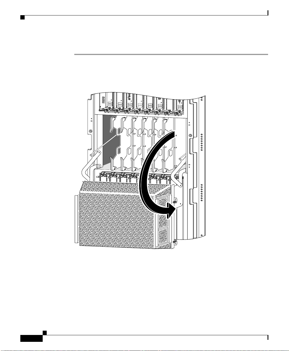
Step 1 Loosen the 4 captive screws on the air filter door and pivot the door open
(Figure 5-4).
Figure 5-4 Opening the Chassis Air Filter Door
ENABLED
FAIL
0
CSC
1
0
1
SFC
ALARM
2
Q OC-3/STM-POS
6DS3–SMB P
/
H
/
F
RX
TX
11
RX
12DS3–SMB P
/
H
/
F
OC-48/STM-16-SCPOS
Chapter 5 Maintaining the Router
OC-12/STM-4 ATM
FAST ETERNET
ROUTE PROCESSOR
5-8
138149
Cisco XR 12416 Router Installation Guide
OL-13833-01
Page 9
Chapter 5 Maintaining the Router
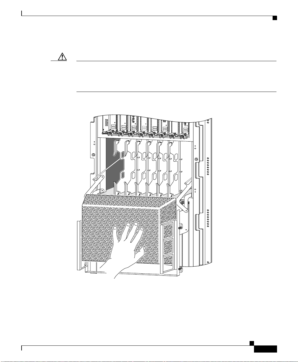
Step 2 Lift up the air filter and carefully slide it out of the door (Figure 5-5).
Caution Be careful not to damage the honeycomb screens on the back of the
air filter door and in the fabric card cage. Damage to the honeycomb
screens can restrict airflow, cause overheating, and affect EMI
performance.
Figure 5-5 Removing the Chassis Air Filter
Cleaning or Replacing the Chassis Air Filter
6DS3–SMB P
/
H
/
F
RX
TX
11
RX
12DS3–SMB P
/
H
/
F
OC-48/STM-16-SCPOS
OC-12/STM-4 ATM
FAST ETERNET
ROUTE PROCESSOR
ENABLED
FAIL
0
Q OC-3/STM-POS
CSC
1
0
1
SFC
ALARM
2
OL-13833-01
138150
Cisco XR 12416 Router Installation Guide
5-9
Page 10
Removing and Replacing Blower Modules
Step 3 Visually check the condition of the air filter to determine whether to clean it or
install a new replacement.
• Dirty—You can vacuum or replace the filter.
Caution Do not vacuum the air filter while it is installed in the chassis. You must remove
the air filter completely before you c lean it to prevent contaminan ts from being
drawn into the bays or cage.
• W orn or torn—If the f ilter appears worn or torn, dispose of it in a responsible
manner and install a replacement air filter (12000/16-FILTER=).
Step 4 Slide the new or cleaned air filter into the air filter door.
Step 5 Close the air filter door and tighten the 4 captive screws.
Caution Align and seat the door carefully to avoid damaging the
EMI-preventi v e gask et contacts on the do or. The air f ilter door mu st
be closed and secured at all times to maintain correct
EMI performance.
Chapter 5 Maintaining the Router
Removing and Replacing Blower Modules
The blower modules support online insertion and removal (OIR), so you can
remove and install a blo wer module while the system remains po wered on without
presenting an electrical hazard or damage to the system. Y ou can replace a blo wer
module while the
preservation.
Caution Although the blower module supports OIR and can be replaced without
interruption to system operation, the system should not operate without a blower
module for more than 3 minutes to prevent overheating.
Cisco XR 12416 Router Installation Guide
5-10
system maintains all routing information and ensures session
OL-13833-01
Page 11
Chapter 5 Maintaining the Router
Removing and Replacing Blower Modules
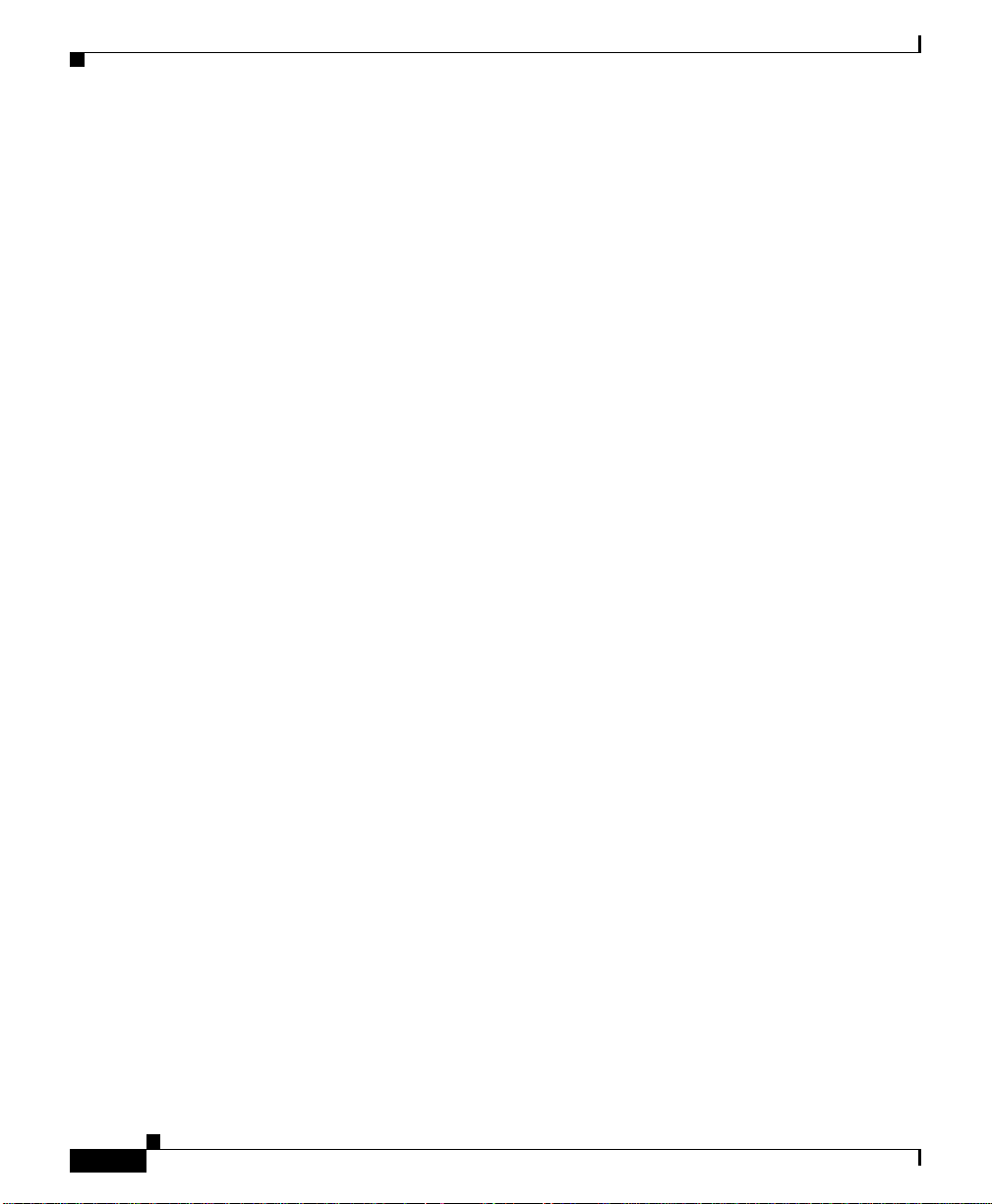
Upper and Lower Blower Module Orientation
Illustrations in this procedure show the removal and replacement of the upper
blower module. The procedure to replace the lower blower module is the same
except for the orientation of the blower mo dule.
• Heads-up orientation—Install the blower module in the upper bay in the
“heads-up” orientation with the three fan air intake openings face down.
• Heads-down orientation—Install the blower module in the lower blower
module bay in the “heads-down” orientation with the three fan air intake
openings face up.
Use the following procedure to remove and replace the blower modules.
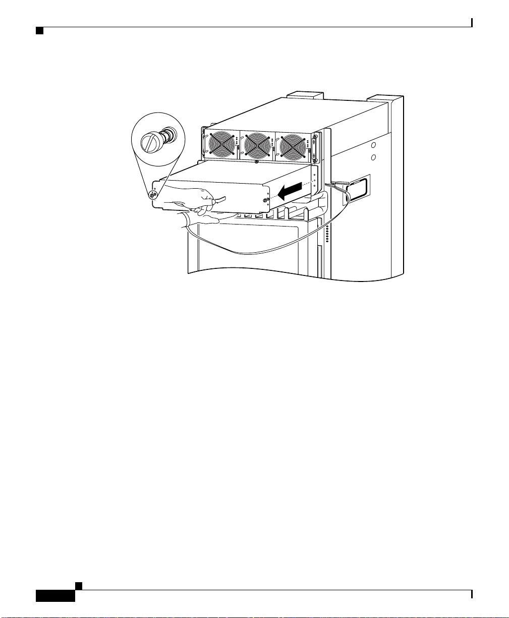
Step 1 Remove the blower module from the chassis (Figure 5-6):
a. Loosen the captive screw on each side of the blower module.
b. Pull out the blower module halfway from the module bay.
c. Slide out the blower module completely from the module bay while
supporting it with your other hand.
OL-13833-01
Warning
The blower module weighs approximately 20pounds (9 kg). Use two hands
when handling the blower module.
Cisco XR 12416 Router Installation Guide
5-11
Page 12
Removing and Replacing Blower Modules
Figure 5-6 Removing the Upper Blower Module
Chapter 5 Maintaining the Router
PWR OK
FAULT
TEMP
I LIM
PWR OK
FAULT
TEMP
I LIM
PWR OK
FAULT
TEMP
I LIM
26213
5-12
Cisco XR 12416 Router Installation Guide
OL-13833-01
Page 13
Chapter 5 Maintaining the Router
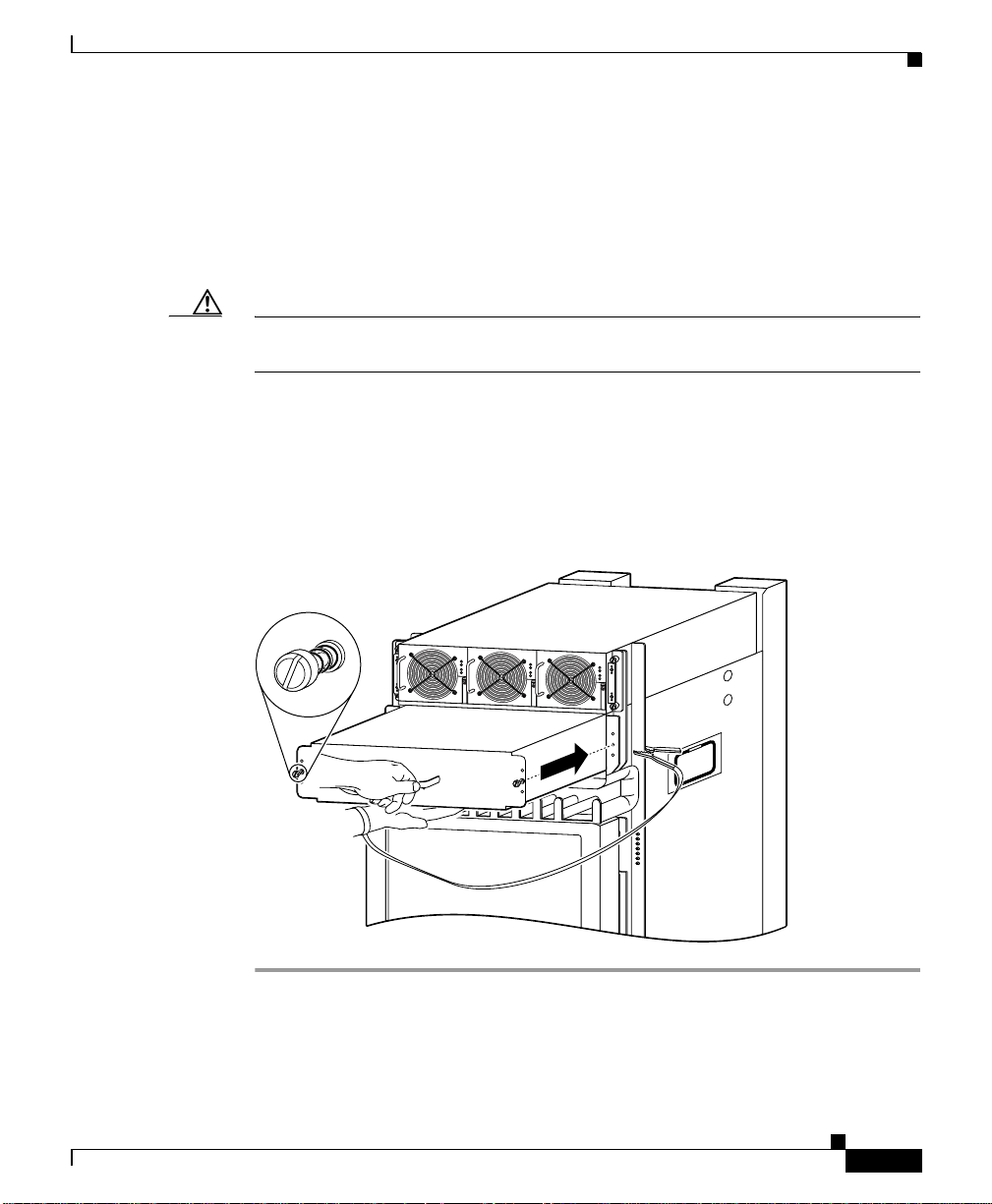
Step 2 Install the new blower module into the chassis (Figure 5-7):
a. Lift the blower module (with two hands) and slide i t halfw ay into the m odule
bay.
b. Slowly push the blower module into the chassis until it mates with the
backplane connector at the back of the module bay.
Caution To prevent damage to the connectors, do not use excessive force when inserting
the blower module into the chassis.
c. Tighten the captive screws on the blower module to secure it to the chassis.
• The (green) OK status indicator on the front of the blower module should
light. If the OK indicator does not li ght, see the “Isolating Cooling Subsys tem
Problems” section on page 4-32.
Figure 5-7 Installing the Upper Blower Module
Removing and Replacing Blower Modules
OL-13833-01
PWR OK
FAULT
TEMP
I LIM
PWR OK
FAULT
TEMP
I LIM
PWR OK
FAULT
TEMP
I LIM
27218
Cisco XR 12416 Router Installation Guide
5-13
Page 14
Chapter 5 Maintaining the Router
Removing and Replacing AC and DC Power Subsystem Components
Removing and Replacing AC and DC Power
Subsystem Components
The Cisco XR 12416 router supports online insertion and removal (OIR). If you
are replacing a redundant power supply, you can remove and install the power
supply while the system remains powered on without causing an electrical hazard
or damage to the system. This feature enables you replace a power supply while
the
system maintains all routing information and ensures session preservation.
However, to maintain operational redundancy, proper cooling, and meet EMI
compliance standards, you must have all three (standard) or four (optional)
working power supplies installed. When you remove a failed power supply with
the router in operation, perform the replacement as quickly as possible. Make sure
you have the tools and the replacement power supply ready before beginning the
removal and installation procedure.
Removing and Replacing an AC Power Supply
5-14
This section provides the procedure to remove an AC power supply from the
standard single-level AC power shelf. The procedure to remove an AC-input
power supply from the optional double-level AC-input power shelf are identical
to these; only the slot locations for AC-input power supplies are different.
Cisco XR 12416 Router Installation Guide
OL-13833-01
Page 15
Chapter 5 Maintaining the Router
27836
Figure 5-8 shows AC power shelves housing the power supplies.
Figure 5-8 Standard and Optional AC Power Shelves
Removing and Replacing AC and DC Power Subsystem Components
PWR OK
FAULT
TEMP
I LIM
a
Standard AC-input power shelf
PWR OK
FAULT
TEMP
I LIM
PWR OK
FAULT
TEMP
I LIM
b
Optional AC-input power shelf
PWR OK
FAULT
TEMP
I LIM
PWR OK
FAULT
TEMP
I LIM
PWR OK
FAULT
TEMP
I LIM
PWR OK
FAULT
TEMP
I LIM
OL-13833-01
Cisco XR 12416 Router Installation Guide
5-15
Page 16
Removing and Replacing AC and DC Power Subsystem Components
Figure 5-9 identifies the components of the AC power supply.
Figure 5-9 AC Power Supply Components
1
2
Pwr Ok
Fault
Temp
Chapter 5 Maintaining the Router
OC
129495
5-16
Pwr Ok
Fault
1 Ejector handle 2 Captive screw
Cisco XR 12416 Router Installation Guide
Temp
OC
OL-13833-01
Page 17
Chapter 5 Maintaining the Router
To remove and replace an AC power supply, use the following procedure.
Step 1 Unplug the power supply cord from its AC outlet.
Step 2 Power off the circuit breaker assigned to that AC outlet.
Removing and Replacing AC and DC Power Subsystem Components
Warning
T o ensure that po wer remains off while yo u are performing thi s procedure, tape
the circuit breaker switch in the off (0) position.
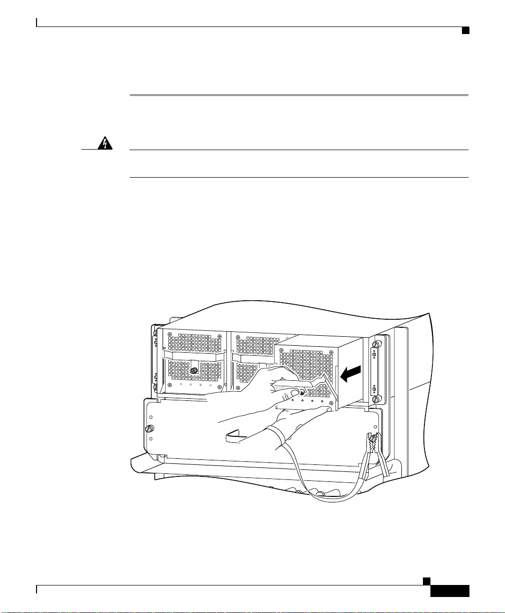
Step 3 Remove the PEM from the power shelf (Figure 5-10):
a. Loosen the captive screw to release the ejector handle.
b. Pivot the ejector handle down to eject the power supply from its backplane
connector.
c. Slide the po wer supply o ut of its bay while suppo rting it with your ot her hand.
Figure 5-10 Removing an AC Power Supply
Pwr Ok
Fault
Temp
OC
Pwr Ok
Fault
Temp
OC
Pwr Ok
Fault
Temp
OC
129497
OL-13833-01
Cisco XR 12416 Router Installation Guide
5-17
Page 18
Removing and Replacing AC and DC Power Subsystem Components
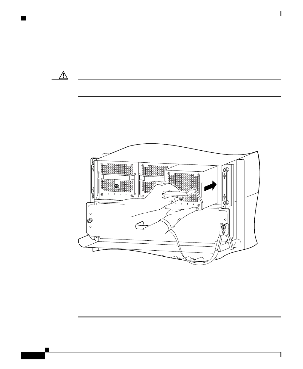
Step 4 Install the new power supply (Figure 5-11):
a. Slide the power supply into the bay until it mates with its backplane
connector.
Caution To prevent damage to the power shelf backplane connector, do not use excessive
force when inserting the power supply into its power shelf bay.
b. Lift up the ejector handle to hook it over the bottom edge of the power shelf.
c. Tighten the captive screw to secure the power supply in the shelf.
Figure 5-11 Installing an AC Power Supply
Chapter 5 Maintaining the Router
5-18
Pwr Ok
Fault
Temp
OC
Pwr Ok
Fault
Temp
OC
Pwr Ok
Fault
Temp
Step 5 Plug the power supply cable into its AC outlet.
Step 6 Power on the circuit breaker to that AC outlet.
After the power-on sequence completes, the (green) PWR OK indicator on the
front of the power supply should light. If the indicator does not light, see the
“Troubleshooting an AC Power Supply” section on page 4-5.
Cisco XR 12416 Router Installation Guide
OC
129496
OL-13833-01
Page 19
Chapter 5 Maintaining the Router
28446
Removing and Replacing the Standard AC-Input Power Shelf
Removing and Replacing the Standard AC-Input
Power Shelf
Use the following procedure to remove and replace the standard AC-input power
shelf.
Caution To remove and replace the power shelf, the system must be powered off. Be sure
to notify the network administrator and other appropriate personnel that all
routing traffic stops while the upgrade takes place.
Step 1 Remove all of the power supplies as described in “Removing and Replacing an
AC Power Supply” section on page 5-14.
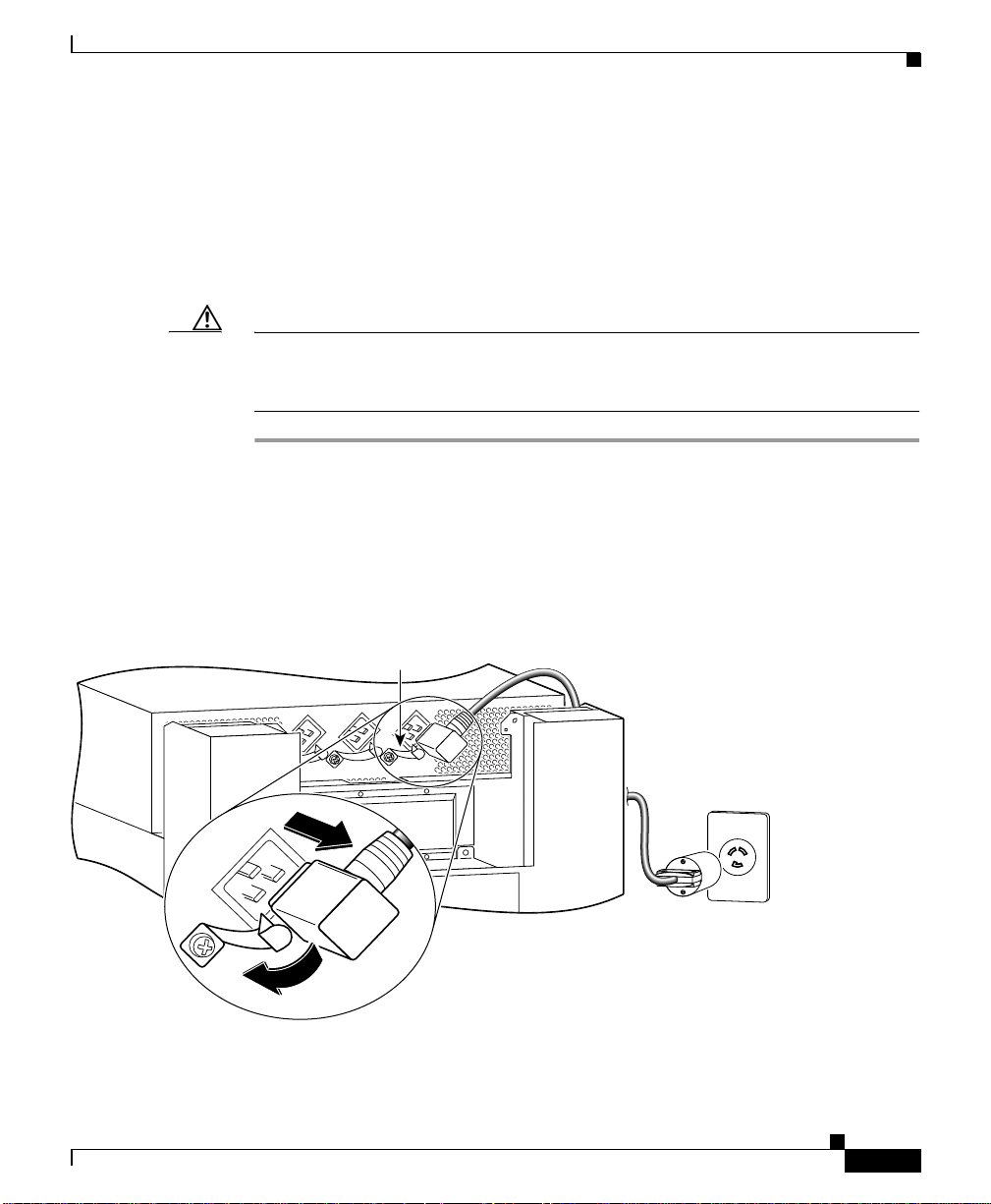
Step 2 Disconnect each of the AC power cords from the back panel of t he po wer shelf b y
lifting the retention clip and unplugging the cord (Figure 5-12).
Figure 5-12 Disconnecting AC Power Cords
OL-13833-01
Power cord
retention clip
Cisco XR 12416 Router Installation Guide
5-19
Page 20
Removing and Replacing the Standard AC-Input Power Shelf
s
e)
j
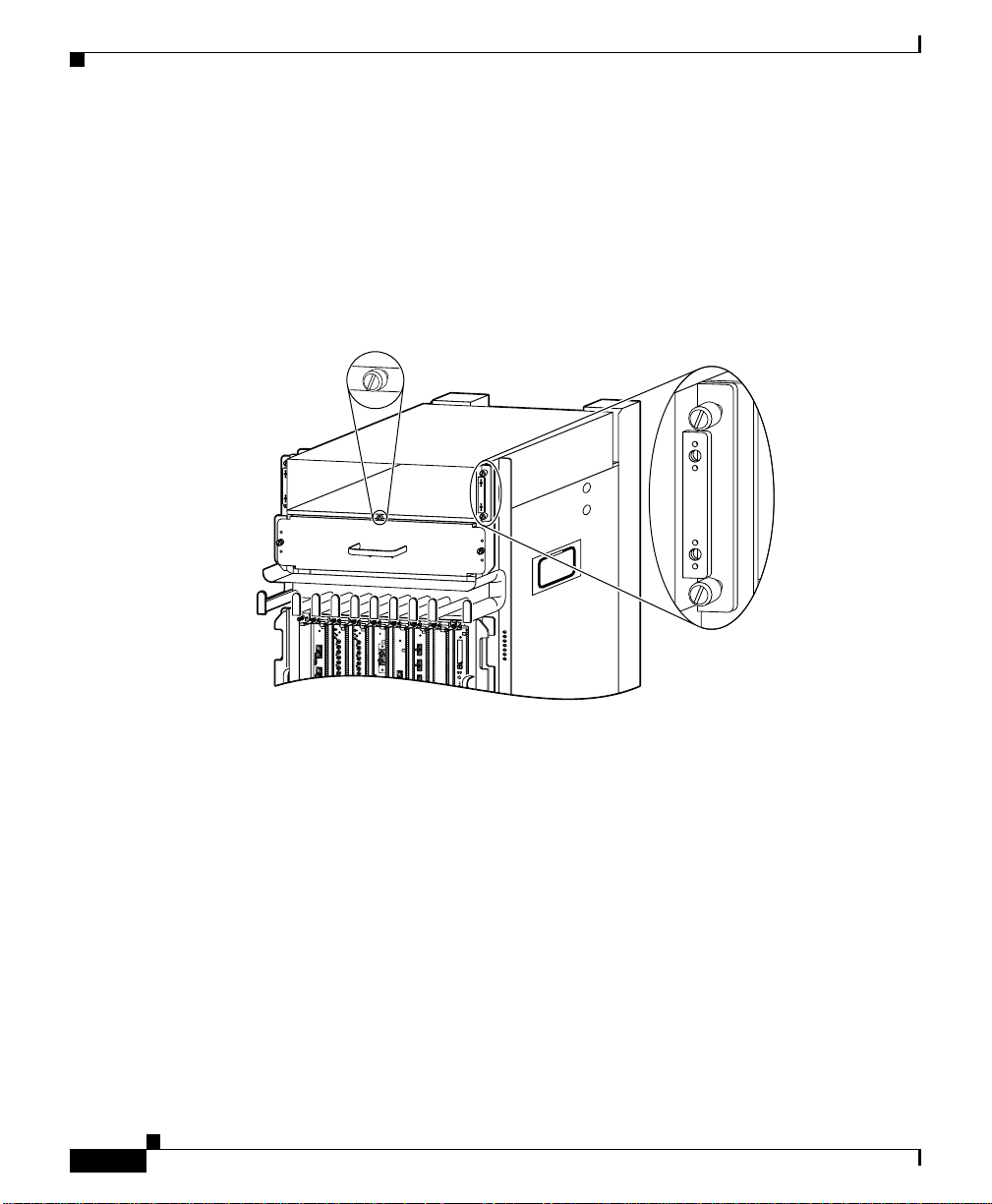
Step 3 Unseat the power shelf from the chassis (Figure 5-13):
a. Loosen the two captive screws on each side of the power shelf.
b. Loosen the ejector jackscrew to unseat the power shelf from the power
interface panel connectors.
Figure 5-13 Unseating the Power Shelf
Ejector
ackscrew
Chapter 5 Maintaining the Router
Captive screw
(2 on each sid
DOWN
LOOP RA LA
DOWN
LOOP RA LA
CDHNT CD
CDHNT CD
TX
TX
0
0
RX
RX
0
TX
TX
1
1
RX
RX
ACTIVE
CARRIER
TX
TX
RX PKT
2
2
RX
RX
TX
TX
1
EJECT
SLOT-0
SLOT-1
RESET
AUX
28020
Cisco XR 12416 Router Installation Guide
5-20
OL-13833-01
Page 21

Chapter 5 Maintaining the Router
n
s
Step 4 Remove the power shelf by grasping the flanges on each side and slowly pulling
the shelf along the chassis track to remove it (Figure 5-14):
Removing and Replacing the Standard AC-Input Power Shelf
Warning
The AC-input power shelf weighs approximately 21 pounds (9.5 kg). Use two
hands to remove the power shelf.
Figure 5-14 Removing the AC-Input Power Shelf
Track o
chassi
DOWN
LOOP RA LA
DOWN
LOOP RA LA
CDHNT CD
CDHNT CD
TX
TX
0
0
RX
RX
0
TX
TX
1
1
RX
RX
ACTIVE
CARRIER
TX
TX
RX PKT
2
2
RX
RX
TX
TX
1
EJECT
SLOT-0
SLOT-1
RESET
AUX
27967
OL-13833-01
Cisco XR 12416 Router Installation Guide
5-21
Page 22

Removing and Replacing the Standard AC-Input Power Shelf
side of chassis)
Elcon connectors
Step 5 Insert the new power shelf halfway into the chassis.
Step 6 Connect the power shelf to the chassis power interface panel connectors
(Figure 5-15):
a. Be sure the holes on each side of the power shelf are aligned with the guide
pins on each side of the chassis.
b. Carefully slide the power shelf into place until its two connectors just mate
with the power interface panel connectors.
Caution To prevent damage to the interface connectors, do not use excessive force when
inserting the power shelf into the chassis.
Figure 5-15 Connecting the AC-Input Power Shelf
on power shelf
back panel
Chapter 5 Maintaining the Router
5-22
Hole
Guide pin
(one on each
Cisco XR 12416 Router Installation Guide
28021
OL-13833-01
Page 23

Chapter 5 Maintaining the Router
s
e)
j
Step 7 Seat the power shelf to the chassis (Figure 5-16):
a. Tighten the ejector jackscrew.
b. Tighten the captive screws on each flange.
Figure 5-16 Seating the Power Shelf
Ejector
ackscrew
Removing and Replacing the Standard AC-Input Power Shelf
Captive screw
(2 on each sid
DOWN
LOOP RA LA
DOWN
LOOP RA LA
CDHNT CD
CDHNT CD
TX
TX
0
0
RX
RX
0
TX
TX
1
1
RX
RX
ACTIVE
CARRIER
TX
TX
RX PKT
2
2
RX
RX
TX
TX
1
EJECT
SLOT-0
SLOT-1
RESET
AUX
28020
Cisco XR 12416 Router Installation Guide
OL-13833-01
5-23
Page 24

Removing and Replacing the Optional 2-Level AC-Input Power Shelf
Power cord
Step 8 Reconnect each of the AC power cords to the back panel of the power shelf and
secure them in place with their retention clips (Figure 5-17).
Figure 5-17 Reconnecting AC Pow er Cords
retention clip
Chapter 5 Maintaining the Router
28019
Step 9
Reinstall the power supplies as described in “Removing and Replacing an AC
Power Supply” section on page 5-14.
Removing and Replacing the Optional 2-Level
AC-Input Power Shelf
Use the following procedure to remove and replace the optional 2-lev el AC-input
power shelf.
Caution To remove and replace the power shelf, the system must be powered off. Notify
the network administrator and other appropriate personnel that all routing traffic
stops while the upgrade takes place.
Cisco XR 12416 Router Installation Guide
5-24
OL-13833-01
Page 25

Chapter 5 Maintaining the Router
Power cord
Removing and Replacing the Optional 2-Level AC-Input Power Shelf
Step 1 Remove all of the po wer suppl ies as described in Removi ng and Replacing an A C
Power Supply, page 5-14.
Step 2 Disconnect each of the AC power cords from the back panel of t he po wer shelf b y
lifting the retention clip and unplugging the cord (Figure 5-18).
Figure 5-18 Disconnecting the AC Power Cords
retention clip
OL-13833-01
129493
Cisco XR 12416 Router Installation Guide
5-25
Page 26

Removing and Replacing the Optional 2-Level AC-Input Power Shelf
n
s
Step 3 Loosen the two captive screws on each side of the power shelf.
Step 4 Loosen the ejector jackscrew to unseat the power shelf from the connectors on the
chassis power interface panel.
Step 5 Remove the power shelf by grasping the flanges on each side and slowly pulling
the shelf along the chassis track to remove it (Figure 5-19).
Chapter 5 Maintaining the Router
Warning
The AC-input power shelf weighs approximately 42 pounds (19.05 kg). Use two
hands to remove the power shelf.
Figure 5-19 Removing the AC-Input Po wer Shelf
Track o
chassi
DOWN
LOOP RA LA
DOWN
LOOP RA LA
CDHNT CD
CDHNT CD
TX
TX
0
0
RX
RX
0
TX
TX
1
1
RX
RX
ACTIVE
CARRIER
TX
TX
RX PKT
2
2
RX
RX
TX
TX
1
EJECT
SLOT-0
SLOT-1
RESET
AUX
33450
5-26
Cisco XR 12416 Router Installation Guide
OL-13833-01
Page 27

Chapter 5 Maintaining the Router
side of chassis)
Removing and Replacing the Optional 2-Level AC-Input Power Shelf
Step 6 Insert the new power shelf halfway into the chassis.
Step 7 Connect the power shelf to the chassis power interface panel connectors
(Figure 5-20):
a. Be sure the holes on each side of the power shelf are aligned with the guide
pins on each side of the chassis.
b. Carefully slide the power shelf into place until its two connectors just mate
with the power interface panel connectors.
Caution To prevent damage to the interface connectors, do not use excessive force when
inserting the power shelf into the chassis.
Figure 5-20 Connecting the AC-Input Power Shelf
OL-13833-01
Hole
Guide pin
(one on each
Elcon connectors
on power shelf
back panel
33451
Cisco XR 12416 Router Installation Guide
5-27
Page 28

Removing and Replacing the Optional 2-Level AC-Input Power Shelf
n
s
Step 8 Install the power shelf by grasping the flanges on each side and sl owl y sliding the
shelf into the chassis along the track (Figure 5-21):
a. Tighten the ejector jackscrew.
b. Tighten the two captive screws on each flange.
Figure 5-21 Installing the AC-Input Power Shelf
DOWN
LOOP RA LA
DOWN
LOOP RA LA
CDHNT CD
CDHNT CD
TX
TX
0
0
RX
RX
0
TX
TX
1
1
RX
RX
ACTIVE
CARRIER
TX
TX
RX PKT
2
2
RX
RX
TX
TX
1
Chapter 5 Maintaining the Router
Track o
chassi
EJECT
SLOT-0
SLOT-1
RESET
AUX
33450
5-28
Cisco XR 12416 Router Installation Guide
OL-13833-01
Page 29

Chapter 5 Maintaining the Router
33452
Power cord
Step 9 Reconnect each of the AC power cords to the back panel of the power shelf and
secure them in place with their retention clips (Figure 5-22).
Figure 5-22 Reconnecting AC Power Cords
retention clip
Removing and Replacing the Optional 2-Level AC-Input Power Shelf
OL-13833-01
Step 10
Reinstall the power supplies as described in “Removing and Replacing an AC
Power Supply” section on page 5-14 beginning with Step 6.
Cisco XR 12416 Router Installation Guide
5-29
Page 30

Chapter 5 Maintaining the Router
Upgrading to the Optional AC Power Shelf
Upgrading to the Optional AC Power Shelf
Use the following procedure to upgrade you r router from the standard, 1-le vel A C
power shelf to an optional, 2-level AC power shelf.
Note A router with an optional, 2-level po wer shelf is 77.5 inches (196.85 cm) in height
and does not fit into a standard 7-foot rack.
Step 1 Remove the standard one-level power shelf following the procedures in
“Removing and Replacing the Standard AC-Input Power Shelf” section on
page 5-19 through Step 4.
Step 2 Install the optional, 2-level power shelf following the procedures in “Removing
and Replacing the Optional 2-Leve l A C-In put Po wer Shelf” section on page 5-24
beginning with Step 6.
Step 3 Replace the old cover with the new cover you received in the upgrade kit.
a. Hold the front cover by its outside edges and align the four ball studs on the
back of the cover with the sockets on the front of the chassis.
b. Push in the fro nt co v er until al l four ball stu ds snap into their sockets and th e
front cover is flush against the front of the chassis.
5-30
Cisco XR 12416 Router Installation Guide
OL-13833-01
Page 31

Chapter 5 Maintaining the Router
Removing and Replacing a DC PEM
This section contains the procedure to remove and replace an DC PEM from the
chassis. Before you begin this procedure, read the “The Cisco XR 12416 router
supports online insertion and removal (OIR). If you are replacing a redundant
power supply, you can remove and install the power supply while the system
remains powered on without causing an elect rical hazard or damage to the system.
This feature enables you replace a power supply while the system maintains all
routing information and ensures session preservation.” section on page 5-14.
Removing and Replacing a DC PEM
OL-13833-01
Cisco XR 12416 Router Installation Guide
5-31
Page 32

Removing and Replacing a DC PEM
Figure 5-23 identifies the components of a DC power supply.
Figure 5-23 DC Power Supply Components
Chapter 5 Maintaining the Router
2
1
3
PWR OK
FAULT
TEMP
OC
5-32
4
PWR OK FAULT TEMP OC
129494
1 Handle 3 Ejector lever
2 Fan 4 Power switch
Cisco XR 12416 Router Installation Guide
OL-13833-01
Page 33

Chapter 5 Maintaining the Router
Use the following procedure to remove and replace a DC PEM.
Step 1 Power off the PEM by switching its circuit breaker off.
Step 2 Power off the DC circuit breaker assigned to that PEM.
Removing and Replacing a DC PEM
Warning
T o ensure that po wer remains off while yo u are performing thi s procedure, tape
the circuit breaker switch in the off (0) position.
Step 3 Loosen the captive screw on the ejector handle and pivot the lever down to eject
the PEM from its bay (Figure 5-24).
Step 4 Remove the PEM from the power shelf (Figure 5-24):
a. Pull the PEM halfway out of its bay.
b. Slide the PEM out of its bay while supporting it with your other hand.
Warning
The DC PEM weighs approximately 6 pounds (2.7 kg). Use two hands to remove
the power supply.
OL-13833-01
Cisco XR 12416 Router Installation Guide
5-33
Page 34

Removing and Replacing a DC PEM
Figure 5-24 Removing a DC PEM
Chapter 5 Maintaining the Router
PWR OK
FAULT
TEMP
c
Pull module
out of shelf
a
PWR OK
FAULT
TEMP
Loosen
captive
screw
Pivot
b
ejector
lever
PWR OK
FAULT
TEMP
PWR OK
FAULT
TEMP
26212
5-34
Cisco XR 12416 Router Installation Guide
OL-13833-01
Page 35

Chapter 5 Maintaining the Router
Step 5 Install the new DC PEM into the power shelf (Figure 5-25):
a. Slide the PEM halfway into the chassis.
b. Slowly push the power supply into the chassis until it mates with the
backplane connector at the back of the bay.
c. Positi on the bottom of th e ejector le v er in the slot on th e bottom of the power
shelf and lift the ejector lever into place to seat the PEM to the backplane
connector.
Caution To prevent damage to the power shelf backplane connector, do not use excessive
force when inserting the PEM into its power shelf bay.
d. Tighten the captive screw to secure the PEM in the power shelf.
Note Because the PEM is powered redundantly by other PEMs in its power load zone,
the fault indicator may go on. This can happen even if the circuit breaker for that
PEM is switched off, or if there is no DC source power to the PEM. When power
is supplied to the PEM and the circuit breaker is switched on, the fault indicator
should go off and the PWR OK indicator should light.
Removing and Replacing a DC PEM
OL-13833-01
Cisco XR 12416 Router Installation Guide
5-35
Page 36

Removing and Replacing a DC PEM
r
le
w
Figure 5-25 Installing a DC PEM
a
Loosen captive
screw and pivot
ejector lever
b
Slide power module
into power shelf bay
Chapter 5 Maintaining the Router
Close ejecto
c
lever to seat
power modu
Tighten
d
captive scre
PWR OK
FAULT
TEMP
Step 6 Power on the DC circuit breaker assigned to that PEM.
Step 7 Power on the PEM by switching on its circuit breaker.
PWR OK
FAULT
TEMP
PWR OK
FAULT
TEMP
PWR OK
FAULT
TEMP
After the power-on sequence completes, the (green) PWR OK indicator on the
front of the PEM should light. If the indicator does not light, see the
“Troubleshooting a DC Power Supply” section on page 4-10.
27214
5-36
Cisco XR 12416 Router Installation Guide
OL-13833-01
Page 37

Chapter 5 Maintaining the Router
27219
Removing and Replacing the DC Power Shelf
Removing and Replacing the DC Power Shelf
Use the following procedure to remove and replace the DC-input power shelf.
Caution To remove and replace the power shelf, the system must be powered off. Notify
the network administrator and other appropriate personnel that all routing traffic
stops while the upgrade takes place.
Step 1 Remove all of the DC PEMs as described in the “Removing and Replacing a DC
PEM” procedure on page 5-31 through Step 4.
Step 2 Remove the power cable cover by loosening its retaining screw (Figure 5-26).
Figure 5-26 Removing the Source DC Power Cable Cover
Cover standoff
Cover with slotted screw hole;
+
fastens to standoff in middle
of cable connection area.
Ground
–
OL-13833-01
Cisco XR 12416 Router Installation Guide
5-37
Page 38

Removing and Replacing the DC Power Shelf
Step 3 Measure the voltag e acro ss e ach pair o f pos it ive (+) and ne g a tive (–) terminal s of
the power shelf to be sure they are not receiving power.
• All readings should be 0 VDC.
Chapter 5 Maintaining the Router
Warning
Do not proceed if all readings are not 0 (zero) volts. Make sure that the router is
powered off and that all source DC circuit breakers are switched off. Repeat
Step 3 before continuing.
Step 4 Disconnect each pair of power cables and the ground cable from the DC-input
terminal studs as follows (Figure 5-27):
Caution Before remo ving cables, be sure to note the color for each type of cable (positiv e,
negative, and ground). Because there is no color code standard for source DC
wiring, you must be sure which power cables are connected to the proper positive
(+) and negative (–) terminal studs. Typically, green (or green and yellow)
indicate a ground cable, while power cable leads may be labeled positive (+) or
negative (–). Because this is not always the case, the safest way to indicate the
polarity of a cable is to note its color and identify it as described in this procedure.
Warning
When disconnecting source DC power cables, always disconnect the ground
cable last.
Beginning with terminal studs A1 (Figure 5-27):
a. Remove the nut and washer from the negative (–) terminal studs and
disconnect the cable.
• Label the cable. For example: A1-.
b. Remove the nut and washer from the positive (+) terminal studs and
disconnect the cable.
5-38
• Label the cable. For example: A1+.
Repeat steps a. and b. for the remaining pairs of terminal studs.
c. After all po wer cables are disconnected, remove the nut and w asher from t he
ground terminal studs and disconnect the ground cable.
• Label the cable as “ground”.
Cisco XR 12416 Router Installation Guide
OL-13833-01
Page 39

Chapter 5 Maintaining the Router
cable lug
Figure 5-27 Disconnecting the Source DC Power Cables
Removing and Replacing the DC Power Shelf
B1
A1-
A1+
A2-
A2+ B2+
Negative (–)
B1+
B2-
Positive (+)
cable lug
B1- Ground
+
–
Ground
28018
OL-13833-01
Cisco XR 12416 Router Installation Guide
5-39
Page 40

Removing and Replacing the DC Power Shelf
Captive screws
e)
j
Step 5 Unseat the power shelf from the chassis (Figure 5-28):
a. Loosen the two captive screws on each side of the power shelf.
b. Loosen the ejector jackscrew to unseat the power shelf from the connectors
on the chassis power interface panel.
Chapter 5 Maintaining the Router
Warning
The DC-input power shelf weighs approximately 10.2 pounds (4.6 kg). Use two
hands to remove the power shelf.
Figure 5-28 Unseating the Power Shelf
Ejector
(2 on each sid
ackscrew
DOWN
LOOP RA LA
DOWN
LOOP RA LA
CDHNT CD
CDHNT CD
TX
TX
0
0
RX
RX
0
TX
TX
1
1
RX
RX
ACTIVE
CARRIER
TX
TX
RX PKT
2
2
RX
RX
TX
TX
1
EJECT
SLOT-0
SLOT-1
RESET
AUX
28020
5-40
Cisco XR 12416 Router Installation Guide
OL-13833-01
Page 41

Chapter 5 Maintaining the Router
n
s
Step 6 Remove the power shelf by grasping the flanges on each side and slowly pulling
the shelf along the chassis track to remove it (Figure 5-29):
Figure 5-29 Removing the DC-Input Pow er Shelf
Removing and Replacing the DC Power Shelf
Track o
chassi
DOWN
LOOP RA LA
DOWN
LOOP RA LA
CDHNT CD
CDHNT CD
TX
TX
0
0
RX
RX
0
TX
TX
1
1
RX
RX
ACTIVE
CARRIER
TX
TX
RX PKT
2
2
RX
RX
TX
TX
1
EJECT
SLOT-0
SLOT-1
RESET
AUX
27967
OL-13833-01
Cisco XR 12416 Router Installation Guide
5-41
Page 42

Removing and Replacing the DC Power Shelf
28452
Elcon connectors
Step 7 Insert the new power shelf halfway into the chassis.
Step 8 Connect the power shelf to the chassis power interface panel connectors
(Figure 5-30):
a. Be sure the holes on each side of the power shelf are aligned with the guide
pins on each side of the chassis.
b. Carefully slide the power shelf into place until its two connectors just mate
with the power interface panel connectors.
Caution To prevent damage to the interface connectors, do not use excessive force when
inserting the power shelf into the chassis.
Figure 5-30 Connecting the DC-Input Power Shelf
on power shelf
back panel
Chapter 5 Maintaining the Router
5-42
Hole
Guide pin
(one on each
side of chassis)
Cisco XR 12416 Router Installation Guide
OL-13833-01
Page 43

Chapter 5 Maintaining the Router
Captive screws
e)
j
Step 9 Seat the power shelf to the chassis (Figure 5-31):
a. Tighten the ejector jackscrew.
b. Tighten the captive screws on each flange.
Removing and Replacing the DC Power Shelf
Warning
The DC-input power shelf weighs approximately 10.2 pounds (4.6 kg). Use two
hands to remove the power shelf.
Figure 5-31 Seating the DC-Input Power Shelf
Ejector
(2 on each sid
ackscrew
DOWN
LOOP RA LA
DOWN
LOOP RA LA
CDHNT CD
CDHNT CD
TX
TX
0
0
RX
RX
0
TX
TX
1
1
RX
RX
ACTIVE
CARRIER
TX
TX
RX PKT
2
2
RX
Step 10
RX
TX
TX
1
Reconnect the ground and each pair of power cables to the DC-input terminal
studs as follows (Figure 5-32):
EJECT
SLOT-0
SLOT-1
RESET
AUX
28020
Caution Be sure to connect the cables according to the color coding notes and labels you
made in Step 4.
OL-13833-01
Cisco XR 12416 Router Installation Guide
5-43
Page 44

Removing and Replacing the DC Power Shelf
)
cable lug
Chapter 5 Maintaining the Router
Warning
When reconnecting source DC power cables, always connect the ground cable
first.
a. Reconnect the ground cable to the ground terminal studs.
Beginning with terminal studs B2:
b. Reconnect the positive cable to the positive (+) terminal studs. For example:
B2+.
c. Reconnect the neg ativ e cable to the neg ativ e (–) terminal studs. For exampl e:
B2-.
Repeat steps b and c for the remaining pairs of terminal studs.
Figure 5-32 Reconnecting the Source DC Power Cables to the Power Shelf
5-44
Cisco XR 12416 Router Installation Guide
Positive (+)
cable lug
Negative (–)
26866
Ground (
cable lug
OL-13833-01
Page 45

Chapter 5 Maintaining the Router
27219
Ground
Step 11 Power on the source DC circuit breakers for the PEMs.
Step 12 Verify the polarity and voltage readings across the pairs of positive and negative
terminal studs:
• All voltage readings should be –48 to –60 VDC
Caution If any of the voltage readings are not within the specified range, do not proceed.
Check for correct polarity and DC source voltage.
Step 13 Reinstall the power cable cover (Figure 5-33).
Figure 5-33 Reinstalling the Source DC Power Cable Cover
+
Cover standoff
–
Removing and Replacing the DC Power Shelf
OL-13833-01
Cover with slotted screw hole;
fastens to standoff in middle
of cable connection area.
Step 14 Power off the source DC circuit breakers for the PEMs.
Step 15 Install all of the DC PEMs as described in the “Removing and Replacing a DC
PEM” procedure on page 5-31 beginning with Step 5.
Cisco XR 12416 Router Installation Guide
5-45
Page 46

Chapter 5 Maintaining the Router
Removing and Replacing Cards from the Chassis
Removing and Replacing Cards from the Chassis
This section contains the procedures to remove cards from the card cages in the
chassis. For additional information about specific types of cards, see Chapter 1,
“Product Overview”.
Removing and Replacing RP and Line Cards from the Upper and Lower Card Cages
This section describes the procedures for removing and installing a router
processor (RP) card or a line card from the upper or lower card cage. The upper
and lower card cages have 9 slots, and the lower card cage is a reverse image of
the top card cage. Alarm cards can only be installed in th eir specific slot s which
are labeled as “Alarm Card”.
Caution Handle all cards b y th e metal car d carrier edges on ly; a v oid t ouching the board or
any connector pins. After removing a card, carefully place it in an antistatic bag
or similar environment to protect it from ESD and dust in the optic ports
(fiber-optic line cards).
5-46
Use the following procedure to remove and replace a line card or RP from the card
cage:
Step 1 Disconnect any cables from the card.
Cisco XR 12416 Router Installation Guide
OL-13833-01
Page 47

Chapter 5 Maintaining the Router
52644
Removing and Replacing Cards from the Chassis
Step 2 Remove t h e ca r d :
a. Loosen the captive screws at the top and bottom of the front panel
(Figure 5-34a).
b. Pivot the ejector levers to unseat the card from the backplane connector
(Figure 5-34b.)
c. Slide the card out of the slot (Figure 5-34c) and place it directly into an
antistatic bag or other ESD-preventive container.
Figure 5-34 Removing a Line Card from the Line Card and RP Card Cage
a
a
Loosen
Loosen
captive
captive
screws
screws
Pivot ejector
Pivot ejector
b
b
levers away
levers away
from card to
from card to
unseat card
unseat card
c
c
Grasp card carrier to
Grasp card carrier to
slide card out of slot
slide card out of slot
0
0
ACTIVE
ACTIVE
CARRIER
CARRIER
RX PKT
RX PKT
1
1
ACTIVE
ACTIVE
CARRIER
CARRIER
RX PKT
RX PKT
2
2
ACTIVE
ACTIVE
CARRIER
CARRIER
RX PKT
RX PKT
3
3
ACTIVE
ACTIVE
CARRIER
CARRIER
RX PKT
RX PKT
Q OC-3/STM-POS
Q OC-3/STM-POS
ALARM A
ALARM B
ALARM A
ALARM B
DOWN
DOWN
LOOP RA LA
LOOP RA LA
CDHNT CD
CDHNT CD
TX
TX
0
0
RX
RX
TX
TX
1
1
RX
RX
TX
TX
2
2
RX
RX
TX
TX
3
3
CRITICAL
RX
RX
MAJOR
TX
TX
MINOR
4
4
RX
RX
TX
TX
5
5
RX
RX
ACO/LT
ALARM
ENABLED
FAIL
ENABLED
FAIL
0
CSC
1
6DS3–SMB P
6DS3–SMB P
0
1
SFC
ALARM
2
/
/
H
H
/
/
F
F
DOWN
LOOP RA LA
CDHNT CD
TX
0
RX
TX
1
RX
TX
2
RX
TX
3
RX
TX
4
RX
TX
5
RX
TX
6
RX
TX
7
RX
TX
8
RX
TX
9
RX
TX
10
RX
TX
11
RX
12DS3–SMB P
/
H
/
F
MBUS
CSC
SFC
A
B
MINOR
MAJOR
FAIL
ENABLE
A
B
0
1
0
1
CRITICAL
2
3
4
ACTIVE
0
CARRIER
RX PKT
ACTIVE
CARRIER
RX CELL
OC-48/STM-16-SCPOS
OC-12/STM-4 ATM
FAST ETERNET
EJECT
EJECT
SLOT-0
SLOT-1
SLOT-0
SLOT-1
RESET
RESET
AUX
AUX
CONSOLE
CONSOLE
LINK
LINK
COLL
COLL
TX
TX
RX
RX
MII
MII
RJ-45
RJ-45
ROUTE PROCESSOR
ROUTE PROCESSOR
OL-13833-01
Step 3
Replace the card by reversing the procedures in Steps 1 and 2.
Cisco XR 12416 Router Installation Guide
5-47
Page 48

Removing and Replacing Cards from the Chassis
Removing and Replacing an Alarm Card
The router is equipped with two alarm cards. One card occupies the dedicated far
left slot of the upper card cage; the second occupies the dedicated far right slot of
the lower card cage (see Figure 5-35).
The alarm card slot differs from the rest of the card cage slots: it is physically
narrower, has a different backplane connector, and is labeled as an “Alarm Card”
slot. Alarm cards can only be installed in these two slots.
Chapter 5 Maintaining the Router
5-48
Cisco XR 12416 Router Installation Guide
OL-13833-01
Page 49

Chapter 5 Maintaining the Router
U
L
Removing and Replacing Cards from the Chassis
Figure 5-35 Alarm Card Locations in the Upper and Lower Card Cages
DOWN
LOOP RA LA
DOWN
LOOP RA LA
CDHNT CD
pper card cage
CRITICAL
MAJOR
MINOR
ACO/LT
ALARM
Alarm card
ENABLED
FAIL
ENABLED
FAIL
0
CSC
1
0
1
SFC
ALARM
2
0
ACTIVE
CARRIER
RX PKT
1
ACTIVE
CARRIER
RX PKT
2
ACTIVE
CARRIER
RX PKT
3
ACTIVE
CARRIER
RX PKT
Q OC-3/STM-POS
CDHNT CD
TX
TX
0
0
RX
RX
TX
TX
1
1
RX
RX
TX
TX
2
2
RX
RX
TX
TX
3
ACTIVE
3
0
CARRIER
RX
RX
RX PKT
TX
TX
4
4
RX
RX
TX
TX
5
5
RX
RX
TX
6
RX
TX
7
RX
TX
8
RX
TX
9
RX
TX
10
RX
TX
11
RX
12DS3–SMB P
6DS3–SMB P
/
/
H
H
/
/
F
F
OC-48/STM-16-SCPOS
ACTIVE
CARRIER
RX CELL
OC-12/STM-4 ATM
FAST ETERNET
EJECT
SLOT-0
SLOT-1
RESET
AUX
CONSOLE
LINK
COLL
TX
RX
MII
RJ-45
ROUTE PROCESSOR
F
F
/
/
H
H
/
/
2
ALARM
SFC
1
0
6DS3–SMB P
1
CSC
Q OC-3/STM-POS
0
FAIL
ENABLED
FAIL
ENABLED
RX PKT
CARRIER
ACTIVE
3
ALARM
RX PKT
CARRIER
ACTIVE
ACO/LT
RX
5
2
TX
RX
4
RX PKT
MINOR
CARRIER
TX
MAJOR
ACTIVE
CRITICAL
RX
3
1
TX
RX
2
RX PKT
TX
CARRIER
ACTIVE
RX
1
TX
0
RX
0
TX
CDHNT CD
LOOP RA LA
DOWN
Alarm card
ower card cage
ROUTE PROCESSOR
FAST ETERNET
OC-12/STM-4 ATM
12DS3–SMB P
RX
OC-48/STM-16-SCPOS
11
TX
RX
RJ-45
MII
RX
TX
COLL
LINK
CONSOLE
AUX
RESET
SLOT-1
SLOT-0
EJECT
RX CELL
CARRIER
ACTIVE
10
TX
RX
9
TX
RX
8
TX
RX
7
TX
RX
6
TX
RX
5
TX
RX
4
TX
RX PKT
RX
CARRIER
0
3
ACTIVE
TX
RX
2
TX
RX
1
TX
RX
0
TX
CDHNT CD
LOOP RA LA
DOWN
27965
Cisco XR 12416 Router Installation Guide
OL-13833-01
5-49
Page 50

Removing and Replacing Cards from the Chassis
Use the following procedure to remove and replace an alarm card from either the
top or bottom card cage.
Caution To ensure proper alarm card screw alignment, line card slots adjacent to the alarm
cards must always be populated.
Step 1 Disconnect any cables from the alarm card.
Step 2 Remove the alarm card:
a. Loosen the captive screws at the top and bottom of the front panel
(Figure 5-36a).
b. Pull the card out of the slot (Figure 5-36b) and place it directly into an
antistatic bag or other ESD-preventive container.
Figure 5-36 Removing an Alarm Card from the Upper Card Cage
Chapter 5 Maintaining the Router
5-50
a
Loosen
captive
screws
Use handle to pull
b
card out of slot
Step 3
Cisco XR 12416 Router Installation Guide
Replace the card by reversing the procedures in Steps 1 and 2.
DOWN
LOOP RA LA
DOWN
LOOP RA LA
CDHNT CD
CDHNT CD
TX
TX
0
0
RX
RX
0
TX
TX
1
1
RX
RX
ACTIVE
CARRIER
TX
TX
RX PKT
2
2
RX
RX
TX
TX
1
3
ACTIVE
3
0
CARRIER
RX
RX
ACTIVE
CARRIER
RX PKT
2
ACTIVE
CARRIER
CRITICAL
MAJOR
MINOR
ACO/LT
ALARM
ENABLED
FAIL
ENABLED
FAIL
0
CSC
1
0
1
SFC
ALARM
2
3
Q OC-3/STM-POS
RX PKT
ACTIVE
CARRIER
RX PKT
RX PKT
TX
TX
4
4
RX
RX
TX
TX
5
5
RX
RX
TX
6
RX
TX
7
RX
TX
8
RX
TX
9
RX
TX
10
RX
TX
11
RX
12DS3–SMB P
6DS3–SMB P
/
/
H
H
/
/
F
F
OC-48/STM-16-SCPOS
ACTIVE
CARRIER
RX CELL
OC-12/STM-4 ATM
FAST ETERNET
EJECT
SLOT-0
SLOT-1
RESET
AUX
CONSOLE
LINK
COLL
TX
RX
MII
RJ-45
ROUTE PROCESSOR
28347
OL-13833-01
Page 51

Chapter 5 Maintaining the Router
Removing and Replacing Cards from the Chassis
Removing and Replacing Switch Fabric Cards
The switch fabric card cage is located behind the air filter door on the front of the
chassis. The card cage has five keyed, vertical card slots for the CSCs and SFCs.
CSCs are installed in the left two card slots (labeled CSC 0 and 1); SFCs are
installed in the right thre e card slots (labeled SFC 0, 1, and 2).
Use the following procedure to remove and replace switch fabric cards.
Step 1 Loosen the 4 captive screws on the air filter door and pivot the door open
(Figure 5-37).
Figure 5-37 Opening the Chassis Air Filter Door
6DS3–SMB P
/
H
/
F
RX
TX
11
RX
12DS3–SMB P
/
H
/
F
OC-48/STM-16-SCPOS
OC-12/STM-4 ATM
FAST ETERNET
ROUTE PROCESSOR
ENABLED
FAIL
0
Q OC-3/STM-POS
CSC
1
0
1
SFC
ALARM
2
OL-13833-01
138149
Cisco XR 12416 Router Installation Guide
5-51
Page 52

Removing and Replacing Cards from the Chassis
A
Step 2 Remove t h e ca r d :
a. Pivot the ejector levers to unseat the card from the backplane connector.
b. Grasp the card by its metal card carrier and slide the card out of the slot
(Figure 5-38).
–
Place the card directly into an antistatic bag or other ESD-preventive
container.
Figure 5-38 Removing a Card from the Switch Fabric Card Cage
Switch fabric card
Chapter 5 Maintaining the Router
ir filter door
26862
Step 3
Step 4 Close the air filter door and tighten the captive screws.
Cisco XR 12416 Router Installation Guide
5-52
To install the card, reverse the procedure in Step 2.
OL-13833-01
Page 53

Chapter 5 Maintaining the Router
Removing and Installing a Chassis
This section provides the procedures to remove and replace a chassis. You may
need to perform this procedure to replace a defecti ve chassis or mov e it to another
location. These instructions include the steps directing you to removal and
replacement instructions for individual components such as power supplies and
line cards.
Because you are removing all the components (except the air filter) from the
defective chassis and then reinstalling them in the replacement chassis, the
procedures that follow are based on the following prerequisites:
• The replacement chassis, mounted on its own scissor-jack platform, is
temporarily placed within reach of the rack in which the defective chassis is
installed, and is temporarily connected to the same g rounding system as t he
defective chassis.
• A spare scissor-jack platform with the anchor clips and bolts (that came with
the original chassis) is available to remove the defective chassis from the
equipment rack.
• Components are transferred from the defective chassis directly to the
replacement chassis.
• The replacement chassis is installed in the equipment rack after all
components are installed.
Removing and Installing a Chassis
OL-13833-01
This approach has the adv antage of protec ting system components against damage
by eliminating the need to store them, even temporarily, outside their card cages.
It also helps ensure that the physical configuration of the router is maintained
because each transferred component is installed in the same location in the
replacement chassis that it occupied in the defective chassis.
Procedures for removing and installing the chassis are described in the following
sections:
• Preparing the Replacement Chassis, page 5-54
• Preparing the Installed Chassis for Removal, page 5-54
• Removing and Installing System Components, page 5-55
• Removing and Installing System Components, page 5-55
• Removing the Chassis from the Equipment Rack, page 5-56
• Installing the Replacement Chassis, page 5-61
Cisco XR 12416 Router Installation Guide
5-53
Page 54

Removing and Installing a Chassis
Preparing the Replacement Chassis
Before you can begin to install components in the replacement chassis, you need
to temporarily connect the central office grounding system or interior equipment
grounding system. You can make this connection when the replacement chassis
and scissor-jack platform has been placed near the rack site.
See “NEBS Supplemental Unit Bonding and Grounding Guidelines” section on
page 2-21 for information about making these connections.
Preparing the Installed Chassis for Removal
Use the following procedure to prepare the installed chassis for removal.
Step 1 Power off the router (see Powering Off the Router, page 5-2).
Step 2 Power off the circuit breakers to the power supplies.
Step 3 Disconnect the power cords from the power shelf:
Chapter 5 Maintaining the Router
5-54
• For a standard AC power shelf, see Step 2 of Removing and Replacing the
Standard AC-Input Power Shelf, page 5-19.
• For an optional AC power shelf, see Step 2 of Removing and Replacing the
Optional 2-Level AC-Input Power Shelf, page 5-24.
• For a DC power shelf, see Steps 2, 3, and 4 of Removing and Replacing the
DC Power Shelf, page 5-37.
Step 4 Remove the front doors (see Removing and Installing Front Doors, page 5-3).
Step 5 Disconnect RP cables connected to the console port, auxiliary port, or either of
the Ethernet ports, RJ-45 or MII.
Label each of the RP cables before you disconnect the cables.
Cisco XR 12416 Router Installation Guide
OL-13833-01
Page 55

Chapter 5 Maintaining the Router
Step 6 Disconnect the cables from each alarm card.
Label each of the alarm card cables before you disconnect them.
Step 7 Disconnect the line card interface cables:
a. Identify th e type of li ne card and its slo t number. Write this information on a
piece of paper before you disconnect the cables. You’ll need this information
when you reinstall the line cards.
b. Identify the line card cable and its port connection. Label the cable with this
information.
c. Loosen the captive screw at each end of the line card cable-management
bracket and pull the cable-management bracket away from the line card.
d. Carefull y remo ve the cables from the ca ble tray and careful ly pl ace th e cab le
bundle out of the way.
e. Repeat steps a through d for each line card.
Step 8 Remove the vertical cable-management troughs (see Attaching the Vertical
Cable-Management Trough, page 3-23).
Removing and Installing a Chassis
Removing and Installing System Components
Use the following procedure to remove and install system components from one
chassis to another.
Step 1 Remove the blower modules and then install them into the replacement chassis.
(see the “Removing and Replacing Blower Modules” section on page 5-10).
Step 2 Remove the power supplies and the power shelf and then install them into the
replacement chassis (see “Removing and Replacing AC and DC Power Subsystem
Components” section on page 5-14).
Step 3 Remove the cards from all three card cages and then install them into the
replacement chassis (see “Removing and Replacing Cards from the Chassis”
section on page 5-46).
Cisco XR 12416 Router Installation Guide
OL-13833-01
5-55
Page 56

Chapter 5 Maintaining the Router
Removing and Installing a Chassis
Removing the Chassis from the Equipment Rack
Use the following procedure to remove the chassis from the equipment rack.
Warning
Step 1 Remove all grounding connecti ons to the chassis (See “NEBS Suppl emental Unit
Two people are required to remove the chassis from the equipment rack.
Bonding and Grounding Guidelines” section on page 2-21).
Step 2 Position the scissor-jack platform from the original router shipping package in
front of the rack-mounting platform in the rack (Figure 5-39).
Step 3 Turn the scissor-jack screw counterclockwise to slowly raise the top of the
scissor-jack platform to the same height as the top of the rack-mo unting platform.
(Figure 5-39.)
Figure 5-39 Positioning the Scissor-Jack Platform to Extract the Chassis
29158
5-56
Cisco XR 12416 Router Installation Guide
OL-13833-01
Page 57

Chapter 5 Maintaining the Router
Step 4 Working from the top of the chassis down, remove the screws that secure the
chassis to the mounting flanges on the rack (Figure 5-40).
• Set the screws aside for use to install the replacement chassis.
Removing and Installing a Chassis
Warning
The chassis is still supported by the rack-mounting platform installed in the
bottom of the rack, but should be held to prevent the possibility of tipping out of
the front of the rack.
OL-13833-01
Cisco XR 12416 Router Installation Guide
5-57
Page 58

Removing and Installing a Chassis
g
g
g
g
g
Figure 5-40 Removing the Mounting Screws
Chapter 5 Maintaining the Router
Chassis mountin
holes group E
Chassis mountin
holes group D
5-58
Cisco XR 12416 Router Installation Guide
Chassis mountin
holes group C
Chassis mountin
holes group B
Chassis mountin
holes group A
26864
OL-13833-01
Page 59

Chapter 5 Maintaining the Router
F
c
Step 5 Position one person in front of the chassis to support and guide it while the second
person slowly pushes the chassis to slide it off the rack-mounting table and onto
the scissor-jack platform.
Step 6 Install the four chassis anchor clips through the slots in the bottom of the chassis:
Removing and Installing a Chassis
Warning
One person should be holding the side of the chassis to prevent it from tipping.
a. Align the holes with the bolt holes in the platform.
b. Insert and tighten the four bolts to prevent the chassis from shifting on the
scissor-jack platform (Figure 5-41).
Figure 5-41 Securing the Chassis to the Scissor-Jack Platform
ront of
hassis
29157
OL-13833-01
Cisco XR 12416 Router Installation Guide
5-59
Page 60

Removing and Installing a Chassis
C
Step 7 Turn the scissor-jack screw clockwise to slowly lower the scissor-jack platform
(Figure 5-42).
Figure 5-42 Closing the Scissor-Jack Platform to Lowe r the Chassis
Chassis anchor
clip and bolt
(2 on each side)
Front of chassis
RX
6
CARRIER
TX
CONSOLE
AUX
RESET
SLOT-1
SLOT-0
EJECT
RX CELL
CARRIER
ACTIVE
RX PKT
CARRIER
0
ACTIVE
ACTIVE
RX
5
TX
RX
4
TX
RX
3
TX
RX
2
TX
RX
1
TX
RX
0
TX
CDHNT CD
LOOP RA LA
DOWN
ACO/LT
RX
5
2
TX
RX
4
RX PKT
MINOR
CARRIER
TX
MAJOR
ACTIVE
CRITICAL
RX
3
1
TX
RX
2
RX PKT
TX
CARRIER
ACTIVE
RX
1
TX
0
RX
0
TX
CDHNT CD
LOOP RA LA
DOWN
Chapter 5 Maintaining the Router
Scissor-jack
29187
screw
Scissor-jack
platform
ounter-clockwise
expands platform
Step 8
Slide the chassis and scissor-jack platform onto a safety hand truck with outrigger
Clockwise
closes platform
wheels and secure it with the lockin g safety s trap.
–
Move the chassis to a level solid floor where the chassis can be
repackaged for shipping.
–
Use the packaging and unpacking instructions that came with the
replacement chassis to repack and ship a defective chassis to the factory.
Cisco XR 12416 Router Installation Guide
5-60
OL-13833-01
Page 61

Chapter 5 Maintaining the Router
Installing the Replacement Chassis
Use the following procedure to install the replacement rack in the chassis.
Step 1 Disconnect the temporary ground conn ections to the replacement chassis.
Step 2 Install the chassis into the rack (see Rack-Mounting the Router Chassis,
page 3-6).
Step 3 Connect all ground connections to the chassis (see Supplemental Bonding and
Grounding Connections, page 3-19).
Step 4 Attach the vertical cable management troughs (see Attaching the Vertical
Cable-Management Trough, page 3-23).
Step 5 Connect all line card interface cables using the notes and labeling you created
when disconnecting them from the defective chassis.
Step 6 Connect power cables to the router (see Connecting Power to the Power Shelf,
page 3-34).
Step 7 Power on the router.
Removing and Replacing a Power Bus Board Fuse
Removing and Replacing a Power Bus Board Fuse
There are two user-replaceable fuses on the power bus board inside the power
interface panel:
• The fuse labeled F1 protects the MBus controller module.
• The fuse labeled F2 protects the 5.1 VDC bias voltage for the current
monitoring (Imon) signal and the voltage monitoring (Vmon) signals on AC
power subsystems.
Note Fuse F2 is used only in AC-input power shelves. It is not used in DC-input power
shelves. Spane fuses can be ordered from Cisco as part number:
PWR-2A/125V-FUSE=.
Cisco XR 12416 Router Installation Guide
OL-13833-01
5-61
Page 62

Removing and Replacing a Power Bus Board Fuse
28448
of access cover)
Use the following procedure to replace a fuse on the power bus board.
Step 1 Power off the router.
Chapter 5 Maintaining the Router
Warning
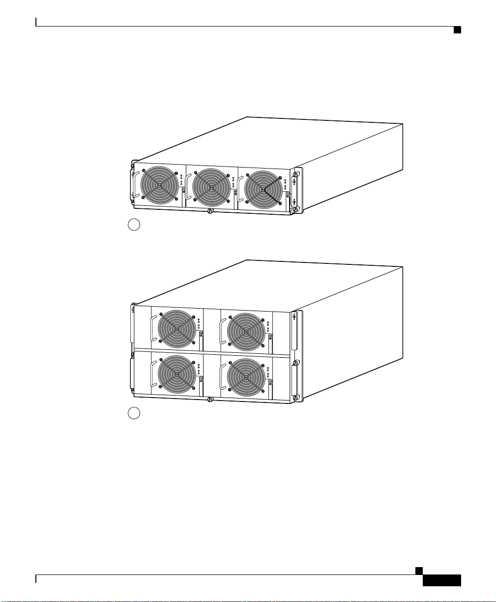
Step 2 Remove t h e pow e r bu s b o a rd M B u s a c ce s s cove r by lo o s en i n g t h e fo u r ca p t ive
The router must be powered down before a fuse can be removed and replaced.
screws (Figure 5-43).
Figure 5-43 MBus Controller Access Cover
Back panel of chassis MBus access cover
Captive screws
(2 on each side
5-62
Step 3 Remove the fuse from the fuse holder using a non-cond ucting fuse extract ion tool
(Figure 5-44).
Step 4 Insert the replacement fuse using the fuse extraction tool to hold the repl acement
fuse, align the fuse with the opening in the fuse holder.
Step 5 Reinstall the MBus access cover.
Step 6 Power on the router.
Cisco XR 12416 Router Installation Guide
OL-13833-01
Page 63

Chapter 5 Maintaining the Router
F
F
F
MBus module
28449
Figure 5-44 Removing and Replacing a Power Bus Board Fuse
1 - MBus
2 - 5.1V bias
use is 2A/125V
Upgrading a Cisco 12000 Series Router to a Cisco XR 12000 Series Router
Screw holes (4)
F2
F1
Fuse
pulling
tool
Fuse
Fuse
holder
Upgrading a Cisco 12000 Series Router to a Cisco XR
12000 Series Router
A Cisco 12416 series router can be upgraded to a Cisco XR 12416 router by
updating the line cards and software images. For information on this process,
including supported line cards and software upgrade procedures, please refer to
the Cisco document, Upgrading a Cisco 12000 Series Router from Cisco IOS
Software to Cisco IOS XR Software.
OL-13833-01
Cisco XR 12416 Router Installation Guide
5-63
Page 64

Upgrading a Cisco 12000 Series Router to a Cisco XR 12000 Series Router
Chapter 5 Maintaining the Router
5-64
Cisco XR 12416 Router Installation Guide
OL-13833-01
 Loading...