

Page 1

Cisco XR 12410 and Cisco XR 12810 Router Installation Guide
March, 2009
Americas Headquarters
Cisco Systems, Inc.
170 West Tasman Drive
San Jose, CA 95134-1706
USA
http://www.cisco.com
Tel: 408 526-4000
800 553-NETS (6387)
Fax: 408 527-0883
Text Part Number: OL-17441-01
Page 2

THE SPECIFICATIONS AND INFORMATION REGARDING THE PRODUCTS IN THIS MANUAL ARE SUBJECT TO CHANGE WITHOUT
NOTICE. ALL STATEMENTS, INFORMATION, AND RECOMMENDATIONS IN THIS MANUAL ARE BELIEVED TO BE ACCURATE BUT
ARE PRESENTED WITHOUT WARRANTY OF ANY KIND, EXPRESS OR IMPLIED. USERS MUST TAKE FULL RESPONSIBILITY FOR
THEIR APPLICATION OF ANY PRODUCTS.
THE SOFTWARE LICENSE AND LIMITED WARRANTY FOR THE ACCOMPANYING PRODUCT ARE SET FORTH IN THE INFORMATION
PACKET THAT SHIPPED WITH THE PRODUCT AND ARE INCORPORATED HEREIN BY THIS REFERENCE. IF YOU ARE UNABLE TO
LOCATE THE SOFTWARE LICENSE OR LIMITED WARRANTY, CONTACT YOUR CISCO REPRESENTATIVE FOR A COPY.
The following information is for FCC compliance of Class A devices: This equipment has been tested and found to comply with the limits for a Class
A digital device, pursuant to part 15 of the FCC rules. These limits are designed to provide reasonable protection against harmful interference when
the equipment is operated in a commercial environment. This equipment generates, uses, and can radiate radio-frequency energy and, if not installed
and used in accordance with the instruction manual, may cause harmful interference to radio communications. Operation of this equipment in a
residential area is likely to cause harmful interference, in which case users will be required to correct the interference at their own expense.
The following information is for FCC compliance of Class B devices: The equipment described in this manual generates and may radiate
radio-frequency energy. If it is not installed in accordance with Cisco’s installation instructions, it may cause interference with radio and television
reception. This equipment has been tested and found to comply with the limits for a Class B digital device in accordance with the specifications in
part 15 of the FCC rules. These specifications are designed to provide reasonable protection against such interference in a residential installation.
However, there is no guarantee that interference will not occur in a particular installation.
Modifying the equipment without Cisco’s written authorization may result in the equipment no longer complying with FCC requirements for Class
A or Class B digital devices. In that event, your right to use the equipment may be limited by FCC regulations, and you may be required to correct
any interference to radio or television communications at your own expense.
You can determine whether your equipment is causing interference by turning it off. If the interference stops, it was probably caused by the Cisco
equipment or one of its peripheral devices. If the equipment causes interference to radio or television reception, try to correct the interference by
using one or more of the following measures:
• Turn the television or radio antenna until the interference stops.
• Move the equipment to one side or the other of the television or radio.
• Move the equipment farther away from the television or radio.
• Plug the equipment into an outlet that is on a different circuit from the television or radio. (That is, make certain the equipment and the television
or radio are on circuits controlled by different circuit breakers or fuses.)
Modifications to this product not authorized by Cisco Systems, Inc. could void the FCC approval and negate your authority to operate the product.
The Cisco implementation of TCP header compression is an adaptation of a program developed by the University of California, Berkeley (UCB) as
part of UCB’s public domain version of the UNIX operating system. All rights reserved. Copyright © 1981, Regents of the University of California.
NOTWITHSTANDING ANY OTHER WARRANTY HEREIN, ALL DOCUMENT FILES AND SOFTWARE OF THESE SUPPLIERS ARE
PROVIDED “AS IS” WITH ALL FAULTS. CISCO AND THE ABOVE-NAMED SUPPLIERS DISCLAIM ALL WARRANTIES, EXPRESSED
OR
IMPLIED, INCLUDING, WITHOUT LIMITATION, THOSE OF MERCHANTABILITY, FITNESS FOR A PARTICULAR PURPOSE AND
NONINFRINGEMENT OR ARISING FROM A COURSE OF DEALING, USAGE, OR TRADE PRACTICE.
IN NO EVENT SHALL CISCO OR ITS SUPPLIERS BE LIABLE FOR ANY INDIRECT, SPECIAL, CONSEQUENTIAL, OR INCIDENTAL
DAMAGES, INCLUDING, WITHOUT LIMITATION, LOST PROFITS OR LOSS OR DAMAGE TO DATA ARISING OUT OF THE USE OR
INABILITY TO USE THIS MANUAL, EVEN IF CISCO OR ITS SUPPLIERS HAVE BEEN ADVISED OF THE POSSIBILITY OF SUCH
DAMAGES.
CCDE, CCENT, Cisco Eos, Cisco HealthPresence, the Cisco logo, Cisco Lumin, Cisco Nexus, Cisco StadiumVision, Cisco TelePresence,
Cisco
WebEx, DCE, and Welcome to the Human Network are trademarks; Changing the Way We Work, Live, Play, and Learn and Cisco Store are
service marks; and Access Registrar, Aironet, AsyncOS, Bringing the Meeting To You, Catalyst, CCDA, CCDP, CCIE, CCIP, CCNA, CCNP, CCSP,
CCVP, Cisco, the Cisco
Cisco
Unity, Collaboration Without Limitation, EtherFast, EtherSwitch, Event Center, Fast Step, Follow Me Browsing, FormShare, GigaDrive ,
HomeLink, Internet Quotient, IOS, iPhone, iQuick Study, IronPort, the IronPort
MeetingPlace Chime Sound, MGX, Networkers, Networking Academy, Network Registrar, PCNow, PIX, PowerPanels, ProConnect, ScriptShare,
SenderBase, SMARTnet, Spectrum Expert, StackWise, The Fastest Way to Increase Your Internet Quotient, TransPath, WebEx, and the We bEx
are registered trademarks of Cisco
Certified Internetwork Expert logo, Cisco IOS, Cisco Press, Cisco Systems, Cisco Systems Capital, the Cisco Systems logo,
logo, LightStream, Linksys, MediaTone, MeetingPlace,
logo
Systems, Inc. and/or its affiliates in the United States and certain other countries.
Page 3

All other trademarks mentioned in this document or website are the property of their respective owners. The use of the word partner does not imply
a partnership relationship between Cisco and any other company. (0812R)
Any Internet Protocol (IP) addresses used in this document are not intended to be actual addresses. Any examples, command display output, and
figures included in the document are shown for illustrative purposes only. Any use of actual IP addresses in illustrative content is unintentional and
coincidental.
Cisco XR12410 and Cisco XR 12810 Router Installation Guide
© 2009 Cisco Systems, Inc. All rights reserved.
Page 4

Page 5

CONTENTS
Preface xi
Changes to This Document xi
Audience xii
Document Organization xii
Document Conventions xiii
Obtaining Documentation and Submitting a Service Request xiv
CHAPTER
1 Product Overview 1-1
Physical and Functional Description of Router 1-1
AC and DC Power Subsystems 1-5
AC Power Entry Modules 1-5
DC Power Supplies 1-7
Switch Fabric and Alarm Card Overview 1-9
Switch Fabric Card Functionality 1-10
Clock Scheduler Card 1-10
Switch Fabric Card 1-11
Alarm Cards and Alarm Display 1-11
Line Card and Route Processor Overview 1-13
Line Cards 1-14
Route Processor 1-14
Performance Route Processor Overview 1-16
PRP PCMCIA Card Slots and Status LEDs 1-18
PRP Ethernet Ports and Status LEDs 1-18
PRP Auxiliary and Console Ports 1-20
PRP-3 LEDs 1-20
PRP Reset Switch 1-21
PRP Alphanumeric Message Displays 1-22
PRP Memory Components 1-23
PRP SDRAM 1-27
PRP SRAM 1-28
PRP NVRAM 1-28
PRP Flash Memory 1-28
Upper and Lower Cable Management Brackets 1-30
OL-17441-01
Upgrading a Cisco 12000 Series Router to a Cisco XR 12000 Series Router 1-30
Cisco XR 12410 and Cisco XR 12810 Router Installation Guide
v
Page 6

Contents
Horizontal Cable Management Bracket 1-31
Blower Module 1-33
CHAPTER
2 Preparing for Installation 2-1
Safety Guidelines 2-2
General Safety Guidelines 2-2
Compliance and Safety Information 2-3
Laser Safety 2-3
Preventing Electrostatic Discharge Damage 2-3
Lifting Guidelines 2-5
Laser Safety 2-5
Site Requirement Guidelines 2-6
Rack-Mounting Guidelines 2-6
Enclosed Rack 2-7
Open Rack 2-7
Telco Rack 2-8
Site Layout and Equipment Dimensions 2-10
Air Flow Guidelines 2-12
Temperature and Humidity Guidelines 2-13
Power Connection Guidelines 2-13
AC-Powered Routers 2-14
DC-Powered Routers 2-15
NEBS Supplemental Unit Bonding and Grounding Guidelines 2-18
Site Wiring Guidelines 2-20
CHAPTER
vi
PRP Port Connection Guidelines 2-22
PRP Auxiliary and Console Port Connections 2-22
PRP Auxiliary Port Signals 2-24
PRP Console Port Signals 2-25
PRP Ethernet Connections 2-26
PRP RJ-45 Ethernet Connections 2-28
Alarm Display Connection Guidelines 2-31
3 Installing the Cisco XR 12410 Router 3-1
Pre-Installation Considerations and Requirements 3-2
Installation Overview 3-3
Required Tools and Equipment 3-4
Unpacking and Positioning the Router 3-4
Removing Components Before Installing the Chassis 3-4
Removing Power Supplies 3-7
Cisco XR 12410 and Cisco XR 12810 Router Installation Guide
OL-17441-01
Page 7

Removing AC PEMs 3-7
Removing DC PEMs 3-8
Removing the Blower Module 3-9
Removing Cards from the Chassis 3-11
Removing Cards from the Line Card and RP Card Cage 3-11
Removing Cards from the Switch Fabric and Alarm Card Cage 3-14
Rack-Mounting the Router Chassis 3-15
Verifying Rack Dimensions 3-17
Installing Rack-Mount Brackets—Optional 3-18
Installing Center-Mount Brackets—Optional 3-20
Installing the Chassis in the Rack 3-23
Supplemental Bonding and Grounding Connections 3-26
Reinstalling Components After Installing the Chassis 3-27
Reinstalling Power Supplies 3-27
Reinstalling AC PEMs 3-28
Reinstalling DC PEMs 3-29
Reinstalling the Blower Module 3-30
Contents
CHAPTER
Reinstalling Cards in the Chassis 3-31
Reinstalling Cards in the Switch Fabric and Alarm Card Cage 3-31
Reinstalling Cards in the Line Card and RP Card Cage 3-33
Connecting Line Card Network Interface Cables 3-34
Connecting PRP Route Processor Cables 3-39
Connecting to the PRP Console Port 3-40
Connecting to the PRP Auxiliary Port 3-41
Connecting to the PRP Ethernet Ports 3-41
Connecting Alarm Display Card Cables 3-43
Connecting Power to the Router 3-44
Connecting Power to an AC-Powered Router 3-45
Connecting Power to a DC-Powered Router 3-46
4 Troubleshooting the Installation 4-1
Troubleshooting Overview 4-2
Troubleshooting Using a Subsystem Approach 4-2
Normal Router Startup Sequence 4-3
Identifying Startup Issues 4-4
OL-17441-01
Troubleshooting the Power Subsystem 4-5
Troubleshooting the AC-Input Power Subsystem 4-5
Troubleshooting the DC-Input Power Subsystem 4-8
Cisco XR 12410 and Cisco XR 12810 Router Installation Guide
vii
Page 8

Contents
Troubleshooting a DC PEM 4-10
Additional Power Subsystem Troubleshooting Information 4-12
Troubleshooting the Power Distribution System 4-14
Troubleshooting the Processor Subsystem 4-15
Performance Route Processor Overview 4-16
PRP PCMCIA Card Slots and Status LEDs 4-17
PRP Ethernet Ports and Status LEDs 4-18
PRP Auxiliary and Console Ports 4-19
PRP Reset Switch 4-19
PRP Alphanumeric Message Displays 4-20
Troubleshooting the Route Processor 4-21
Troubleshooting Using the RP Alphanumeric Display 4-22
Troubleshooting Line Cards 4-29
Troubleshooting Using the Line Card Alphanumeric Display 4-30
Troubleshooting Using the Alarm Display 4-35
Monitoring Critical, Major, and Minor Alarm Status 4-36
CHAPTER
Troubleshooting the Cooling Subsystem 4-37
Blower Module Operation 4-38
Power Supply Operation 4-38
Overtemperature Conditions 4-39
Isolating Cooling Subsystem Problems 4-40
5 Maintaining the Router 5-1
Prerequisites and Preparation 5-2
Powering Off the Router 5-2
Removing and Replacing the Air Filter Door Front Cover 5-3
Cleaning or Replacing the Chassis Air Filter 5-5
Cleaning or Replacing a Chassis Air Filter 5-6
Removing and Replacing the Blower Module 5-9
Troubleshooting the Blower Module Installation 5-11
Removing and Replacing AC and DC Power Subsystem Components 5-12
Installation Guidelines 5-12
Removing and Replacing an AC PEM 5-14
Troubleshooting the AC Power Supply Installation 5-17
Removing and Replacing an AC PDU 5-19
Removing and Replacing a DC PEM 5-23
Troubleshooting a 2800 W DC PEM Installation 5-26
Removing and Replacing a DC PDU 5-28
viii
Removing and Replacing Cards from the Chassis 5-36
Cisco XR 12410 and Cisco XR 12810 Router Installation Guide
OL-17441-01
Page 9

Removing and Replacing Cards from the Line Card and RP Card Cage 5-38
Removing and Replacing Cards from the Switch Fabric and Alarm Card Cage 5-40
Removing and Installing a Chassis 5-41
Removing a Chassis from the Equipment Rack 5-42
Installing a Replacement Chassis in the Equipment Rack 5-44
Packing a Defective Chassis for Shipment 5-45
Contents
APPENDIX
APPENDIX
I
NDEX
A Technical Specifications A-1
Router Specifications A-1
B Site Log B-1
OL-17441-01
Cisco XR 12410 and Cisco XR 12810 Router Installation Guide
ix
Page 10

Contents
Cisco XR 12410 and Cisco XR 12810 Router Installation Guide
x
OL-17441-01
Page 11
Preface
This preface describes the objectives and organization of this document and
explains how to find additional information on related products and services. This
preface contains the following sections:
• Changes to This Document, page xi
• Audience, page xii
• Document Organization, page xii
• Document Conventions, page xiii
• Obtaining Documentation and Submitting a Service Request, page xiv
Changes to This Document
Table 1 provides a list of the changes to this document.
Ta b l e 1 Changes to This Document
Release No. Revision Date Change Summary
3.8.0 OL-17441-01 March 2009 Added Performance Route Processor-3 (PRP-3)
hardware details. PRP-3 has been introduced in Cisco
IOS XR Software Release 3.8.0. PRP-3 will be
supported on Cisco IOS XR Software Release 3.8.0
and later releases.
OL-17441-01
Cisco XR 12410 and Cisco XR 12810 Router Installation Guide
xi
Page 12

Audience
The Cisco XR 12410 and Cisco XR 12810 Router Installation Guide is written for
hardware installers and system administrators of Cisco routers.
This publication assumes that the user has a substantial background in installing
and configuring router and switch-based hardware. The reader should also be
familiar with electronic circuitry and wiring practices, and have experience as an
electronic or electromechanical technician.
Document Organization
This installation and configuration guide is organized into the following chapters
and appendixes:
• Chapter 1, “Product Overview,” provides an introduction to the major
components of Cisco XR 12410 router.
• Chapter 2, “Preparing for Installation,” describes safety considerations,
required tools and equipment, an overview of the installation, and procedures
to perform before the installation.
• Chapter 3, “Installing the Cisco XR 12410 Router,” provides instructions for
installing the hardware and connecting external network interface cables.
• Chapter 4, “Troubleshooting Overview,”provides guidelines for
troubleshooting the router hardware installation.
Preface
xii
• Chapter 5, “Maintaining the Router,” provides removal and replacement
procedures for primary router components or field-replaceable units (FRUs).
• Appendix A, “Technical Specifications,” provides a summary of physical,
electrical, and environmental specifications for the router.
• Appendix B, “Site Log,”provides a sample site log that can be used to record
actions relevant to the operation and maintenance of the router.
• Index
Cisco XR 12410 and Cisco XR 12810 Router Installation Guide
OL-17441-01
Page 13
Preface
Document Conventions
This publication uses the following conventions:
• Ctrl represents the key labeled Control. For example, the key combination
Ctrl-Z means hold down the Control key while you press the z
Command descriptions use these conventions:
• Examples that contain system prompts denote interactive sessions, indicating
the commands that you should enter at the prompt. The system prompt
indicates the current level of the EXEC command interpreter.
For example:
–
The router> prompt indicates that you should be at the user level.
–
The router# prompt indicates that you should be at the privileged level.
Access to the privileged level usually requires a password. Refer to the
related software configuration and reference documentation for
additional information.
• Commands and keywords are in bold font.
• Arguments for which you supply values are in italic font.
key.
• Elements in square brackets ([ ]) are optional.
• Alternative but required keywords are grouped in braces ({ }) and separated
by vertical bars (|).
Caution Means be careful. You are capable of doing something that might result in
equipment damage or loss of data.
Note Means take note. Notes contain helpful suggestions or references to materials not
contained in this manual.
Timesaver Means the described action saves time. You can save time by performing the
action described in the paragraph.
Cisco XR 12410 and Cisco XR 12810 Router Installation Guide
OL-17441-01
xiii
Page 14

Preface
Warning
This warning symbol means danger. You are in a situation that could cause
bodily injury. Before you work on any equipment, be aware of the hazards
involved with electrical circuitry and be familiar with standard practices for
preventing accidents. To see translations of the warnings that appear in this
publication, refer to the Regulatory Compliance and Safety Information
document that accompanied this device.
Obtaining Documentation and Submitting a Service
Request
For information on obtaining documentation, submitting a service request, and
gathering additional information, see the monthly What’s
Documentation, which also lists all new and revised Cisco
documentation, at:
http://www.cisco.com/en/US/docs/general/whatsnew/whatsnew.html
Subscribe to the What’s New in Cisco Product Documentation as a Really Simple
Syndication (RSS) feed and set content to be delivered directly to your desktop using
a reader application. The RSS feeds are a free service and Cisco currently supports
RSS version 2.0.
New in Cisco Product
technical
xiv
Cisco XR 12410 and Cisco XR 12810 Router Installation Guide
OL-17441-01
Page 15

CHA P T E R
Product Overview
This chapter provides an overview of the Cisco XR 12410 and Cisco XR 12810
Routers. It contains physical descriptions of the router hardware and major
components, and functional descriptions of the hardware-related features.
Physical and Functional Description of Router
The router chassis is a sheet-metal enclosure that houses router components.
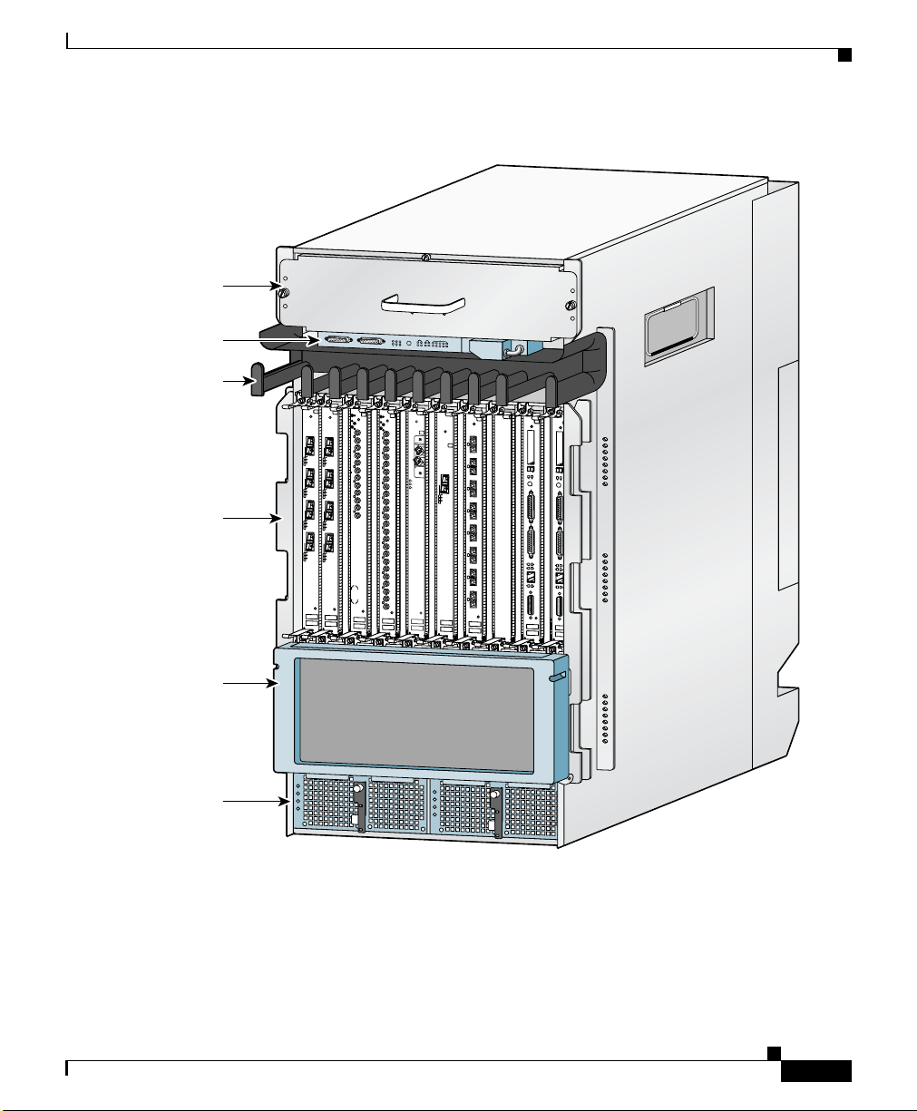
All router models contain the following major components (Figure 1-1):
• Blower module—Supplies cooling air to the router so it does not overheat.
See the
• Alarm display—Monitors various router functions such as power and CSC
and SFC status. See the
page 1-11 for additional information.
• Horizontal cable management bracket—Used to neatly route line card cables.
See the
additional information.
• Line card and Route Processor card cage—Has 10 user-configurable slots that
support a combination of line cards and either one or two route processors
(RPs).
“Blower Module” section on page 1-33 for additional information.
“Alarm Cards and Alarm Display” section on
“Horizontal Cable Management Bracket” section on page 1-31 for
1
OL-17441-01
Cisco XR 12410 and Cisco XR 12810 Router Installation Guide
1-1
Page 16

Physical and Functional Description of Router
• Switch fabric and alarm card cage—Located behind the air filter door, this
card cage contains 7 slots for the switch fabric card set, and two slots for
alarm cards. The switch fabric card set is made up of five switch fabric cards
(SFCs) and two clock scheduler cards (CSCs). See the
Alarm Card Overview” section on page 1-9 for additional information.
• Power Entry Modules—Either two AC power entry modules (PEMs) or two
DC PEMs provide power to the router. See the
Subsystems” section on page 1-5 for additional information.
• Chassis backplane (not shown)—Distributes power to the chassis
components.
Chapter 1 Product Overview
“Switch Fabric and
“AC a n d DC P o w e r
1-2
Cisco XR 12410 and Cisco XR 12810 Router Installation Guide
OL-17441-01
Page 17
Chapter 1 Product Overview
Physical and Functional Description of Router
Figure 1-1 Cisco XR 12410 Router Components—Front View
Blower module
MB
US
C
SC
SF
C
Alarm display
ALA
A
B
R
M
A
R
A
O
L
ARM
N
I
B
M
M
FA
R
O
J
A
R
C
IL
E
L
NABLE
A
C
I
A
T
B
I
0
1
0
1
2
3
4
Horizontal cable
management bracket
Line card and
RP card cage
0
A
C
T
IV
C
A
R
R
R
X
P
K
1
A
C
T
IV
C
A
R
R
R
X
P
K
2
A
C
T
IV
C
A
R
R
R
X
P
K
3
A
C
T
IV
C
A
R
R
R
X
P
K
Q OC-3/STM-POS
DOWN
LOOP RA LA
DOWN
LOOP RA LA
CDHNT CD
CDHNT CD
TX
TX
0
0
RX
0
E
IE
R
T
1
E
IE
R
T
2
E
IE
R
T
3
E
IE
R
T
Q OC-3/STM-POS
RX
TX
TX
1
1
RX
RX
A
C
T
IV
C
E
A
TX
R
TX
R
R
IE
X
P
R
2
K
2
T
RX
RX
TX
TX
3
RX
A
C
T
TX
IV
C
E
A
R
R
R
4
IE
X
P
R
K
T
RX
TX
5
RX
A
C
T
IV
C
E
A
R
R
R
IE
X
P
R
K
T
A
C
T
IV
C
E
A
R
R
R
IE
X
P
R
K
T
6DS3–SMB P
/
H
/
F
3
RX
TX
4
RX
TX
5
RX
TX
6
RX
TX
7
RX
TX
8
RX
TX
9
RX
TX
10
RX
TX
11
RX
12DS3–SMB P
/
H
/
F
ACTIVE
CARRIER
RX PKT
OC-48/STM-16-SCPOS
0
A
C
T
IV
C
E
A
R
R
R
IE
X
C
R
E
L
L
OC-12/STM-4 ATM
FAST ETERNET
E
J
E
E
J
C
T
S
S
L
L
S
S
O
O
L
L
T
T
O
O
-0
1
T
0
R
E
R
A
S
E
U
E
A
S
T
X
U
E
X
CO
CO
NSO
NSO
LE
LE
L
IN
L
K
IN
K
C
O
C
T
L
X
L
T
X
R
X
R
M
II
M
I
I
R
J
R
4
5
ROUTE PROCESSOR
ROUTE PROCESSOR
E
C
T
T
-1
T
O
L
L
X
J
-4
5
Air filter door
(switch fabric
and alarm
behind filter)
Power supplies
OL-17441-01
card cage
52636
A and B
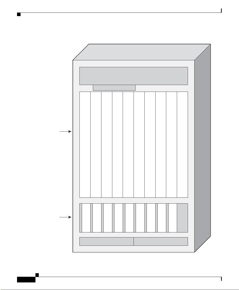
Figure 1-2 shows the slot numbering layout of the router with the location of the
major components. Power is distributed to these components over the chassis
backplane (not shown).
Cisco XR 12410 and Cisco XR 12810 Router Installation Guide
1-3
Page 18
Physical and Functional Description of Router
Figure 1-2 Router Components and Slot-Numbering
Blower module
Alarm display
L
L
L
L
I
I
N
N
E
E
C
C
A
A
R
R
D
D
Line card and
GRP card cage
L
I
I
N
E
C
A
R
D
I
N
N
E
E
C
C
A
A
R
R
D
D
Chapter 1 Product Overview
L
L
L
R
I
I
N
E
C
A
R
D
I
N
N
E
E
C
C
A
A
R
R
D
D
R
P
P
C
C
A
A
R
R
D
D
1
0
1-4
Slot0Slot1Slot2Slot3Slot4Slot5Slot6Slot7Slot8Slot
C
C
S
S
F
C
C
1
0
Switch fabric
and alarm
S
C
0
card cage
Cisco XR 12410 and Cisco XR 12810 Router Installation Guide
9
A
S
S
S
F
F
C
C
1
2
S
F
F
C
C
3
4
A
L
L
A
A
R
R
M
M
0
1
PEM2PEM1
50397
OL-17441-01
Page 19
Chapter 1 Product Overview
AC and DC Power Subsystems
A router ships as either an AC or DC powered system. Source power connects to
power distribution units (PDUs) on the back of the chassis which route power to
the power supplies, also referred to as power entry modules (PEMs).
Caution To ensure that the chassis configuration complies with the required power
budgets, use the on-line power calculator. Failure to properly verify the
configuration may result in an unpredictable state if one of the power units fails.
Contact your local sales representative for assistance.
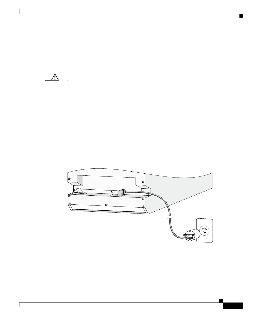
AC Power Entry Modules
An AC powered router consists of two AC PDUs and AC PEMs. AC power to the
router is provided through power cords connected from AC power outlets to the
PDUs on the chassis rear panel as shown in
Figure 1-3 AC PDU Connection
Physical and Functional Description of Router
Figure 1-3.
OL-17441-01
52645
Cisco XR 12410 and Cisco XR 12810 Router Installation Guide
1-5
Page 20
Physical and Functional Description of Router
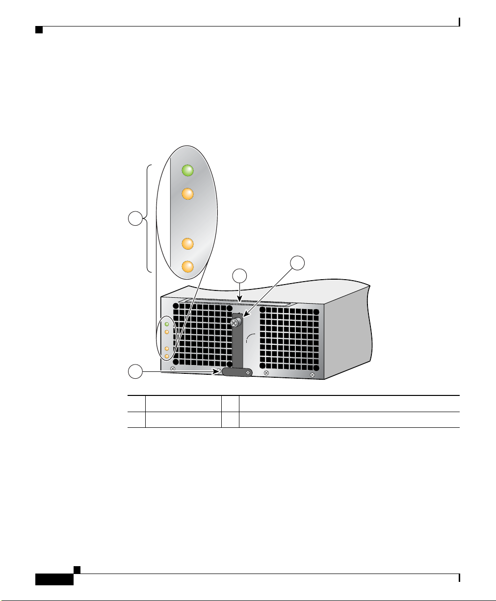
Each AC PEM converts 200 to 240 VAC into -48 VDC, which is distributed
through the chassis backplane to all cards, RPs, and the blower module.
Figure 1-4 identifies the components of an AC PEM.
Figure 1-4 AC PEM Components
PWR OK
FAULT
1
TEMP
Chapter 1 Product Overview
ILIM
3
2
93040
P
W
R
O
K
F
A
U
L
T
T
E
M
P
IL
IM
0
4
1 Status indicators 3 Ejector lever
2 Handle 4 Power On/Off switch (shown in the ON/1 position)
1-6
Cisco XR 12410 and Cisco XR 12810 Router Installation Guide
OL-17441-01
Page 21
Chapter 1 Product Overview
129277
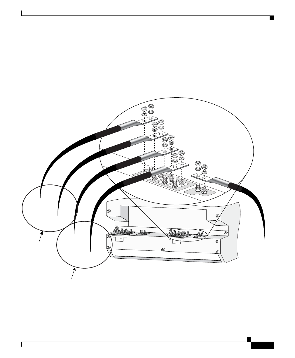
DC Power Supplies
A DC powered router consists of two DC PDUs and DC PEMs. DC power to the
router is provided from cables from a DC power source that are connected to
threaded DC-input terminal studs on the chassis rear panel as shown in
Figure 1-5 DC Power Cables—2800 W DC PDU
Physical and Functional Description of Router
Figure 1-5.
– 48/60V RTN
(+)
– 48/60V (–)
Feed A2
OL-17441-01
– 48/60V (–)
-48/-60V
-40A MAX (2x)
+
–
–
+
-48/-60V
-40A MAX (2x)
+
–
–
+
– 48/60V RTN
(+)
Feed A1
Each DC PEM operates from a nominal source DC voltage of –48 to –60 VDC
and requires a dedicated 60-amp service.
Cisco XR 12410 and Cisco XR 12810 Router Installation Guide
Ground
1-7
Page 22
Physical and Functional Description of Router
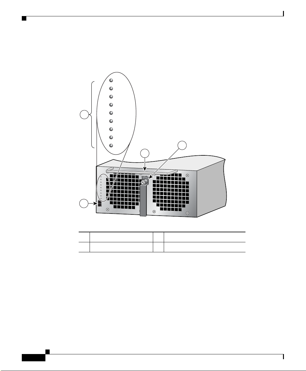
Figure 1-6 identifies the components of a DC power supply.
Figure 1-6 2800 Watt DC PEM Components
F1LO
F2LO
RPF1
RPF2
2
FAIL
OC
OT
INOK
DCOK
Chapter 1 Product Overview
4
3
F1LO
F2LO
RPF1
RPF2
FAIL
OC
OT
INOK
DCOK
1
1 Power on/off switch 3 Handle
2 Status indicators 4 Ejector lever
129275
1-8
Cisco XR 12410 and Cisco XR 12810 Router Installation Guide
OL-17441-01
Page 23

Chapter 1 Product Overview
Switch Fabric and Alarm Card Overview
Switch Fabric and Alarm Card Overview
The switch fabric provides synchronized gigabit-speed connections between line
cards and the route processor. The 9-slot switch fabric and alarm card cage
contain:
• 2 clock scheduler cards (CSCs)
• 5 switch fabric cards (SFCs)
• 2 alarm cards
Note The two alarm cards that are located in the switch fabric and alarm card
cage are not part of the switch fabric.
One CSC and four SFCs are required for an active switch fabric; the second CSC
and the fifth SFC provide redundancy. The combination of CSCs and SFCs make
up the 10-Gbps per-slot switch fabric.
Each SFC or CSC provides a 10-Gbps full-duplex connection to each line card in
the system. For example, in a Cisco XR 12410 and Cisco XR 12810 Routers with
8 line cards, each with 2 x 10
bandwidth is 8 x 20 Gbps = 160 Gbps.
Gbps capacity (full duplex), the system switching
OL-17441-01
Figure 1-2 shows the slot configuration in the switch fabric and alarm card cage.
The labeling identifies the type of card for each slot and can only be seen when
the air filter door is opened.
Note Cisco XR 12410 and Cisco XR 12810 Routers support online insertion and
removal (OIR), which allows you to remove and replace a card while the router
remains powered on.
Cisco XR 12410 and Cisco XR 12810 Router Installation Guide
1-9
Page 24

Switch Fabric and Alarm Card Overview
Switch Fabric Card Functionality
Routers ship from the factory with 2 CSCs and 5 SFCs installed in the 7 slots in
the switch fabric and alarm card cage (see
• CSCs are installed in slot 0 (CSC0) or slot 1 (CSC1).
• SFCs are installed in slot 2 (SFC0), slot 3 (SFC1), slot 4 (SFC2),
slot
5 (SFC3), and slot 6 (SFC4).
Note The enhanced version of the CSC and SFC cards is required for support of BITS,
Single Router APS and Dual Priority features. The enhanced version of the cards
cannot be mixed with the original version fabric cards.
Clock Scheduler Card
Clock scheduler cards provide the following functionality:
• Scheduler—Handles all scheduling requests from the line cards for access to
the switch fabric.
Chapter 1 Product Overview
Figure 1-2).
1-10
• System clock—Supplies the synchronizing signal to all SFCs, line cards, and
the RP. The system clock synchronizes data transfers between line cards or
between line cards and the RP through the switch fabric.
• Switch fabric—Carries user traffic between line cards or between the RP and
a line card. The switch fabric on the CSC is identical to the switch fabric on
the SFC.
The second CSC provides redundancy for the data path, scheduler, and reference
clock. Traffic between the line cards and the switch fabric is monitored constantly.
If the system detects a loss of synchronization (LOS), it automatically activates
the data paths on the redundant CSC so data flows across the redundant paths. The
switch to the redundant CSC occurs within sub-seconds (the actual switch time
depends on your configuration and its scale).
Cisco XR 12410 and Cisco XR 12810 Router Installation Guide
OL-17441-01
Page 25

Chapter 1 Product Overview
Switch Fabric Card
The switch fabric cards augment the traffic capacity of the router. SFCs contain
switch fabric circuitry that can only carry user traffic between line cards or
between the RP and the line cards. SFCs receive all scheduling information and
the system clock signal from the CSCs.
Alarm Cards and Alarm Display
The two alarm cards (in the switch fabric and alarm card cage) provide several
functions:
• Supply +5 VDC to the MBus modules on router components (see AC and DC
Power Subsystems, page 1-5).
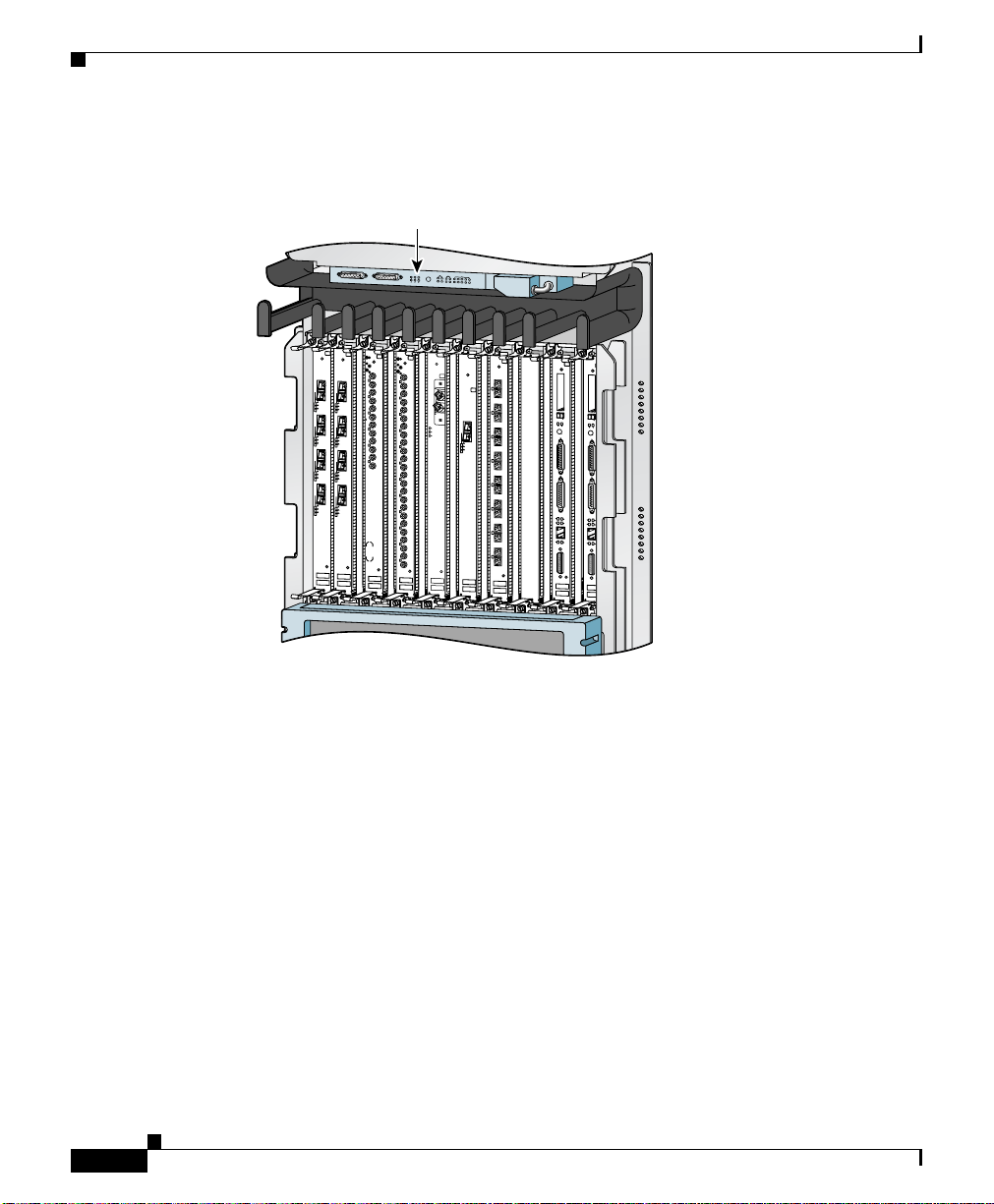
• Work in conjunction with the alarm display to monitor the system. The alarm
display (sometimes referred to as the alarm display card) is above the
horizontal cable management bracket (
Switch Fabric and Alarm Card Overview
Figure 1-7).
OL-17441-01
Cisco XR 12410 and Cisco XR 12810 Router Installation Guide
1-11
Page 26
Switch Fabric and Alarm Card Overview
Figure 1-7 Alarm Display Location
A
0
0
A
C
A
T
C
IV
T
C
IV
E
A
C
E
R
A
R
R
R
IE
R
X
R
IE
P
R
X
P
KT
K
T
1
1
A
C
A
T
C
IV
T
C
IV
E
A
C
E
R
A
R
R
R
IE
R
X
R
IE
P
R
X
P
R
K
T
K
T
2
2
A
C
A
T
C
IV
T
C
IV
E
A
C
E
R
A
R
R
R
IE
R
X
R
IE
P
R
X
P
R
K
T
K
T
3
3
A
C
A
T
C
IV
T
C
IV
E
A
C
E
R
A
R
R
R
IE
R
X
R
IE
P
R
X
P
R
K
T
K
T
Q OC-3/STM-POS
Q OC-3/STM-POS
Alarm display
A
LA
R
B
R
M
A
R
R
A
O
L
O
AR
N
J
M B
I
A
M
T
I
M
R
C
DOWN
LOOP RA LA
DOWN
LOOP RA LA
CDHNT CD
CDHNT CD
TX
TX
0
0
RX
RX
TX
TX
1
1
RX
RX
TX
TX
2
2
RX
RX
TX
TX
3
3
RX
RX
TX
TX
4
4
RX
RX
TX
TX
5
5
RX
RX
TX
6
RX
TX
7
RX
TX
8
RX
TX
9
RX
TX
10
RX
TX
11
RX
12DS3–SMB P
6DS3–SMB P
/
/
H
H
/
/
F
F
L
A
C
I
M
BUS
A
ACT
IV
E
CARR
IER
R
X PK
T
OC-48/STM-16-SCPOS
Chapter 1 Product Overview
CS
C
SF
C
FAIL
ENABL
E
B
0
1 0
1
2
3
4
E
J
E
E
J
C
E
T
C
T
S
S
L
L
S
S
O
O
L
L
T
T
O
O
-
-
0
1
T
T
-0
0
A
C
T
IV
C
E
A
R
R
R
IE
X
C
R
E
L
L
OC-12/STM-4 ATM
FAST ETERNET
-1
R
E
R
A
S
E
U
E
A
S
T
X
U
E
T
X
CO
C
NSO
O
NSOLE
LE
L
IN
L
K
IN
K
C
O
C
T
L
O
X
L
T
L
X
L
R
X
R
X
M
II
M
II
R
J
R
-4
J
5
-
4
5
ROUTE PROCESSOR
ROUTE PROCESSOR
1-12
53369
Cisco XR 12410 and Cisco XR 12810 Router Installation Guide
OL-17441-01
Page 27
Chapter 1 Product Overview
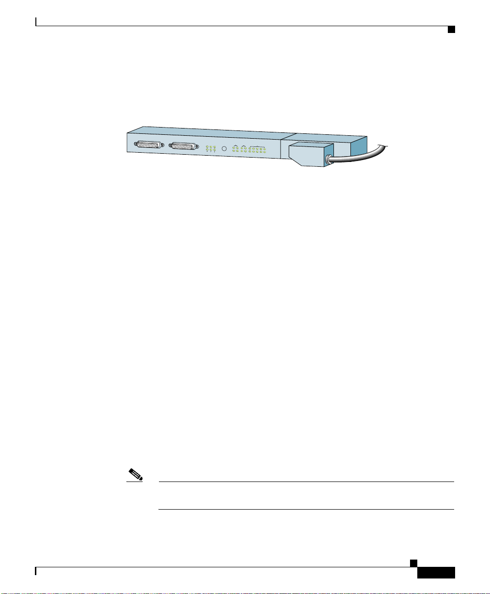
The following connectors and LEDs are on the front panel of the alarm display
(
Figure 1-8):
Figure 1-8 Alarm Display
• Cable connections for the two alarm cards (labeled Alarm A and Alarm B)
• Critical, Major, and Minor LEDs that identify system level alarm conditions
• A pair of status LEDs that correspond to each of the 9 card slots in the switch
Line Card and Route Processor Overview
MBUS
CSC
ALARM A
ALARM B
A
B
R
R
L
O
A
JO
IN
IC
A
M
IT
M
R
C
SFC
FAIL
A
B
ENABLE
0
1
0
1
23
4
53368
fabric and alarm card cage (seven fabric cards and two alarm cards):
–
ENABLED (green)
On—The card installed in that slot is operational and functioning
properly.
Off—Either the slot is empty or the card installed in that slot is faulty.
–
FAIL (yellow)—The card in that slot is faulty.
Line Card and Route Processor Overview
The line card and route processor (RP) card cage has 10 user-configurable slots
that support a combination of line cards and either one or two RPs (see
Figure 1-2). Router configurations can consist of either nine line cards and one
RP, or eight line cards and two RPs (one primary and one redundant) using the
following slot configurations:
• Slots 0 to 7 accommodate the newer (wider) line card designs. These wider
line card slots can also accept narrower legacy line cards.
• Slots 8 and 9 only accept RPs or a narrower legacy line card.
Note If a system uses only one RP install it in slot 9. You can use slot 8 for a
legacy line card.
Cisco XR 12410 and Cisco XR 12810 Router Installation Guide
OL-17441-01
1-13
Page 28

Line Card and Route Processor Overview
Line Cards
Ports and connectors on the line card front panels provide interfaces for external
connections. Line cards communicate with the RP and exchange packet data with
each other through the switch fabric cards.
Caution Any unoccupied card slot in the line card and RP card cage must have a blank
filler panel installed to meet electromagnetic compatibility (EMC) requirements
and to ensure proper air flow through the chassis. Also, if the front panel of a line
card does not completely fill the card slot opening, a narrow card filler panel must
be installed to meet the EMC requirements.
A cable management bracket on the front panel of each line card helps to organize
the interface cables connected to that line card.
The following line cards, SIPs, and SPAs are supported on the Cisco XR 12410
and Cisco XR 12810 Routers:
Chapter 1 Product Overview
–
The Cisco XR 12410 and Cisco XR 12810 Routers supports online
insertion and removal (OIR), allowing you to remove and replace a card
while the router remains powered on.
Note Refer to the current s software release notes for the most up-to-date list of
supported line cards (see
Request” section on page -xiv).
Route Processor
The route processor for the Cisco XR 12410 and Cisco XR 12810 Routers is the
Performance Route Processor-2 (PRP-2) and the Performance Route Processor-3
(PRP-3). For detailed information about the Performance Route Processor, refer
to the Cisco document, Performance Route Processor Installation and
Configuration Guide.
Cisco XR 12410 and Cisco XR 12810 Router Installation Guide
1-14
“Obtaining Documentation and Submitting a Service
OL-17441-01
Page 29

Chapter 1 Product Overview
The PRP-2 and PRP-3 performs the following primary functions:
• Executes routing protocol stacks
• Performs all protocol communications with other routers
• Builds and distributes forwarding information to all line cards
• Uploads the operating system software images to all installed line cards
• Provides out-of-band system console and auxiliary ports and an Ethernet port
• Monitors and manages the power and temperature of system components
The Cisco PRP-2 and PRP-3 delivers all these functions with enhanced
performance and capabilities. It also delivers the following feature enhancements
(depending on the software version running):
• 2 Ethernet management ports
• Hard-drive support (optional part)
• BITS input ports
• 1 GB compact image Flash memory support (optional part)
Line Card and Route Processor Overview
during power-on
for router configuration and maintenance
such as line cards, power supplies, and fans
OL-17441-01
• Memory scalability up to 4 GB with PRP-2 and up to 8 GB with PRP-3.
The PRP-2 and PRP-3 communicates with the line cards either through the switch
fabric or through the MBus. The switch fabric connection is the main data path
for routing table distribution as well as for packets that are sent between the line
cards and the PRP. The MBus connection allows the PRP-2 and PRP-3 to
download a system bootstrap image, collect or load diagnostic information, and
perform general, internal system maintenance operations.
The PRP-2 can be designated as either the Designated System Controller (DSC)
or the Secure Domain router (SDR).
The Designated System Controller (DSC) performs the following functions:
• Implements control plane operations for the chassis
• Monitors temperature and voltage
• Monitors line cards
• On boot up, the first card to become active is designated as the DSC.
Cisco XR 12410 and Cisco XR 12810 Router Installation Guide
1-15
Page 30
Line Card and Route Processor Overview
The Secure Domain Router (SDR) controls domain security features independent
of any other SDRs on the network.
In addition to the functionality listed for the PRP-2, PRP-3 provides the following
specific functions:
• Reduced boot time.
• Increased overall scalability.
• Improved memory access rates and scale.
• Improved CPU performance through dual 1.3-GHz PPC processor cores.
• Improved packet processing using hardware-based acceleration.
• 10-G bandwidth backplane connectivity.
• Support for all 124xx and 128xx chassis, except low–speed fabric (2.5 G).
• New ROMMON that supports IPv4 network configuration directly.
Performance Route Processor Overview
Chapter 1 Product Overview
The performance route processor (PRP) uses a Motorola PowerPC 7450 CPU that
runs at an external bus clock speed of 133 MHz and has an internal clock speed
of 667 MHz.
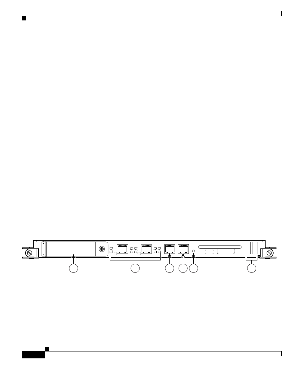
Figure 1-9 identifies the slots, ports, and LEDs on the PRP front panel.
Figure 1-9 Performance Route Processor-2 (PRP-2) Front Panel
EJECT
ETH 1ETH 0 AUX
SLOT-1
SLOT-0
PRIMARY
RX
TX
PRIMARY
EN
LINK
EN
LINK
CONSOLE
RX
TX
RESET
PERFORMANCE ROUTE PROCESSOR 1 (PRP-1)
1 3 4 52 6
Ta b l e 1-1 Performance Route Processor-2 (PRP-2) Front Panel Hardware Components
Cisco XR 12410 and Cisco XR 12810 Router Installation Guide
1-16
129307
OL-17441-01
Page 31

Chapter 1 Product Overview
Line Card and Route Processor Overview
1 PCMCIA flash disk slots (shown with cover in
4 Console serial port
place) and slot LEDs
2 RJ-45 Ethernet ports and data status LEDs 5 Reset button
3 Auxiliary serial port 6 Alphanumeric messages
Figure 1-10 Performance Route Processor 3 (PRP-3) Front Panel
A
K
T
A
INK
IN
L
L
D
T
TA
A
D
T
G
G
I
I
AC
AC
S
S
CONSOLE
AUXBITS 1BITS 0ETH 1ETH 0
1 3 4 52
Ta b l e 1-2 PRP-3 Front Panel Hardware Components Detail
Numeric Callout Hardware Components
1 Ejecter Lever
2 Handle
3 External Compact Flash
4 Reset button
5 Alphanumeric LEDs
RESET
PERFORMANCE RP 3
272359
OL-17441-01
PRP-3 is the route processor for the Cisco XR 12404 and 12804 Router chassis
running Cisco IOS XR Software Release 3.8.0 or a later release. The PRP-3 is
available as product number PRP-3 or PRP-3= for a primary route processor and
is available as PRP-3/R for a redundant route processor. PRP-3 has significant
improvements over PRP-2. These improvements include increased speed,
improved scalability, higher system memory, faster packet processing. Because
PRP-3 does not support Cisco IOS, the bootflash memory no longer exists in
PRP-3. PRP-3 ROMMON has software intelligence to download a Cisco IOS XR
image without the support of bootflash memory.
Cisco XR 12410 and Cisco XR 12810 Router Installation Guide
1-17
Page 32

Line Card and Route Processor Overview
Note PRP-3 supports Cisco XR 12410 (10 G per slot fabric) and Cisco XR 12810 (40
G per slot fabric) Router chassis only. PRP-3 does not support Cisco XR 12004,
12006, 12010, and 12016 Router chassis (2.5 G low-speed fabric).
PRP PCMCIA Card Slots and Status LEDs
Two PCMCIA card slots (slot 0 and slot 1) provide the PRP with additional flash
memory capacity. All combinations of different flash devices are supported by the
PRP. You can use ATA flash disks, Type 1 or Type 2 linear flash memory cards,
or a combination of the two.
Note The PRP only supports +5.2 VDC flash memory devices. It does not support
+3.3 VDC PCMCIA devices.
Status LEDs (Slot-0 / Slot-1) indicate when the flash memory card in that slot is
accessed (see
to remove a flash card from the slot.
Figure 1-9). Each slot has an eject button (located behind the cover)
Chapter 1 Product Overview
Note PRP-3 does not have PCMCIA slots (slot 0 and slot 1). PRP-3 has an external
CompactFlash (disk0:) that replaces the PCMCIA slots.
PRP Ethernet Ports and Status LEDs
The PRP has two 8-pin media-dependent interface (MDI) RJ-45 ports for either
IEEE 802.3 10BASE-T (10
Ethernet connections. These ports are labeled ETH 0 and ETH 1.
The transmission speed of the Ethernet port is not user-configurable. You set the
speed through an autosensing scheme on the PRP which is determined by the
network that the Ethernet port is connected to. However, even at an autosensed
data transmission rate of 100 Mbps, the Ethernet port can only provide a usable
bandwidth of substantially less than 100 Mbps. You can expect a maximum usable
bandwidth of approximately 20 Mbps when using an Ethernet connection.
The following LEDs on the front panel indicate traffic status and port selection
(
Figure 1-11):
Cisco XR 12410 and Cisco XR 12810 Router Installation Guide
1-18
Mbps) or IEEE 802.3u 100BASE-TX (100 Mbps)
OL-17441-01
Page 33

Chapter 1 Product Overview
• LINK, EN, TX, RX—Indicate link activity (LINK), port enabled (EN), data
• PRIMARY—Indicates which Ethernet port is selected (ETH 0 or ETH 1).
Note Because both ports are supported on the PRP, ETH 0 is always on. ETH 1
Figure 1-11 PRP-2 Port Activity LEDs—Partial Front Panel
Line Card and Route Processor Overview
transmission (TX), and data reception (RX).
lights when it is selected.
ETH 1ETH 0
SLOT-1
SLOT-0
PRIMARY
EN
LINK
RX
TX
PRIMARY
EN
LINK
RX
TX
Figure 1-12 PRP-3 Port Activity LEDs—Partial Front Panel
ACT
SIG
ACT
LINK
DATA
DATA
LINK
ETH 1ETH 0
SIG
BITS 0
BITS 1 AUX CONSOLE
70693
272388
OL-17441-01
Cisco XR 12410 and Cisco XR 12810 Router Installation Guide
1-19
Page 34

Line Card and Route Processor Overview
PRP Auxiliary and Console Ports
The auxiliary and console ports on the PRP are EIA/TIA-232 (also known as
RS-232) asynchronous serial ports. These ports connect external devices to
monitor and manage the system.
• The auxiliary port—A (male) plug that provides a data terminal equipment
(DTE) interface. The auxiliary port supports flow control and is often used to
connect a modem, a channel service unit (CSU), or other optional equipment
for Telnet management.
• The console port—A (female) receptacle that provides a data
circuit-terminating equipment (DCE) interface for connecting a console
terminal.
PRP-3 LEDs
The PRP-3 has the following LED indicators:
• Two Ethernet port LEDs used in conjunction with each of the three RJ-45
Ethernet connectors:
Chapter 1 Product Overview
1-20
–
LINK—Indicates link activity
–
DATA—Indicates data transmission or reception
• Two BITS port LEDs used in conjunction with each of the two BITS ports:
–
SIG—Indicates carrier signal available
–
ACT—Indicates that the interface is active
Note BITS feature is not supported in Release 3.8.0.
• One auxiliary port (AUX) and one console port (CONSOLE) LED:
–
AUX—Used as a backup for the command outputs on the Console.
–
CONSOLE—Used for configuring the router by connecting an RJ-45
cable to the console terminal. The router can be configured through the
console terminal.
Cisco XR 12410 and Cisco XR 12810 Router Installation Guide
OL-17441-01
Page 35

Chapter 1 Product Overview
PRP Reset Switch
Caution The reset switch is not a mechanism for resetting the PRP and reloading the
Line Card and Route Processor Overview
Access to the (soft) reset switch is through a small opening in the PRP front panel
(see
Figure 1-9). To press the switch, insert a paper clip or similar small pointed
object into the opening.
Cisco
IOS image. It is intended for software development use only. To prevent
system problems or loss of data, use the reset switch only on the advice of Cisco
service personnel.
Pressing the reset switch causes a nonmaskable interrupt (NMI) and places the
PRP in ROM monitor mode. When the PRP enters ROM monitor mode, its
behavior depends on the setting of the PRP software configuration register. For
example, if the boot field of the software configuration register is set to:
• 0x0—The PRP remains at the ROM monitor prompt (rommon>) and waits for
a user command to boot the system manually.
• 0x1—The system automatically boots the first Cisco IOS image found in
flash memory on the PRP.
OL-17441-01
Cisco XR 12410 and Cisco XR 12810 Router Installation Guide
1-21
Page 36

Line Card and Route Processor Overview
PRP Alphanumeric Message Displays
The alphanumeric message displays are organized in two rows of four LED
characters each (
Figure 1-13 Alphanumeric Message Displays—Partial Front Panel
PROCESSOR
Figure 1-13).
Chapter 1 Product Overview
Upper alphanumeric
LED display (four digits)
Lower alphanumeric
LED display (four digits)
1-22
H10780
The alphanumeric message displays show router status messages during the boot
process, and after the boot process is complete.
• During the boot process, the message displays are controlled directly by the
MBus module.
• After the boot process, the message displays are controlled by Cisco IOS
software (through the MBus).
The alphanumeric message displays also provide information about different
levels of system operation, including the status of the GRP, router error messages,
and user-defined status and error messages
Note A complete, descriptive list of all system and error messages appears in the Cisco
IOS System Error Messages publication.
Cisco XR 12410 and Cisco XR 12810 Router Installation Guide
OL-17441-01
Page 37

Chapter 1 Product Overview
Line Card and Route Processor Overview
PRP Memory Components
This section describes various types of memory used on the PRP to support router
functions.
and Figure 1-14 shows the location on the PRP board.
Ta b l e 1-3 PRP Memory Components
Ty pe Size Quantity Description Location
SDRAM
1
2 GB (default)
or 4 GB
(optional)
3
SRAM
NVRAM
2 MB (fixed) — Secondary CPU cache memory functions —
4
2 MB (fixed) 1 System configuration files, register settings,
HDD 40 GB 1 Contains log and crash information for
Flash
memory
2 GB or 4 GB
(optional)
Compact
Flash
4 MB Boot
ROM
Flash disks5 2
GB (default)
or 4 GB
(optional)
1 GB CF
1. Default SDRAM configuration is 2-GB for PRP-2. Bank 1 (U15) must be populated first. You can use one or both banks to
configure SDRAM combinations of 2 GB and 4 GB for the PRP-2. 1.5-GB configurations.and DIMM devices that are not
from Cisco are not supported.
2. If both banks of the PRP-2 are populated, bank 1 and bank 2 must contain the same size DIMM.
3. SRAM is not user configurable or field replaceable.
4. NVRAM is not user configurable or field replaceable.
5. ATA Flash disks are supported in the PRP-2.
6. Optional PRP-2 hardware. Compact disks that are not from Cisco are not supported.
6
Table 1-3 provides a quick reference of the different types of memory,
1 or 2 2-GB or 4-GB DIMMs (based on desired
SDRAM configuration) for main Cisco IOS
U15 (bank 1)
U18 (bank 2)
XR software functions
—
and logs
—
specific Cisco IOS XR versions.
1 Contains Cisco IOS XR boot image
P3
(bootflash), crash information, and other
user-defined files
1 Stores the ROMMON minimum boot image
—
(MBI).
1 or 2 Contains Cisco IOS XR software images,
system configuration files, and other
user-defined files on up to two flash disks
1 Contains large Cisco IOS XR software
Flash disk
slot 0 and
slot 1
—
images
2
OL-17441-01
Cisco XR 12410 and Cisco XR 12810 Router Installation Guide
1-23
Page 38

Line Card and Route Processor Overview
Figure 1-14 PRP-2 Memory Locations
1
2-40G
P
R
-P
D
H
__
V
E
R
0-01
06
4
-2
0
80
THIS SIDE TO FACEPLATE
Chapter 1 Product Overview
14
1-24
2
K
T
C
EJE
IN
D
L
T-1
LO
S
-0
T
LO
S
3
4
Cisco XR 12410 and Cisco XR 12810 Router Installation Guide
13
12
A
A
K
T
A
IN
L
ETH 1ETH 0
T
T
T
A
IG
C
C
A
SIGA
S
D
CONSOLE ETH 2AUX
BITS 1BITS 0
7 8 9 105 6
ETH 2
PERFORMANCE ROUTE PROCESSOR 2
RESET
11
101105
OL-17441-01
Page 39

Chapter 1 Product Overview
Figure 1-15 PRP-3 Memory Locations
5
Line Card and Route Processor Overview
4
3
1 SDRAM DIMM: Bank 1 - Socket number U8
2 SDRAM DIMM: Bank 2 - Socket number U10
3 External CompactFlash
4 Hard disk (80 GB)
5 Internal CompactFlash
272360
1
2
OL-17441-01
Cisco XR 12410 and Cisco XR 12810 Router Installation Guide
1-25
Page 40

Chapter 1 Product Overview
Line Card and Route Processor Overview
Ta b l e 1-4 PRP-3 Memory Components
Ty pe Size Quantity Description Location
SDRAM
NVRAM
1
3
2 GB (Default) for each
DDR2 DRAM for a total
system memory of 4 GB,
option for upgrade to total
system memory of 8 GB (4
GB each).
2 Two 2-GB default DDR2
DRAM for main CiscoIOSXR
software functions. Provision
for optional upgrade to 4 GB
also possible to provide total
system memory of 8 GB.
2 MB (fixed) 1 System configuration files,
U8 (bank
2
1)
U10 (bank
2)
—
register settings, and logs
Flash memory 2 GB (default) or 4 GB
(optional) Flash disks
4
2
(Internal
and
External
Compact
Contains Cisco IOS XR
software images, system
configuration files, and other
user-defined files on two
CompactFlash.
Internal and
External
Compact
5
Flash
Flash)
Flash boot
ROM
6
HDD
8 MB 1 Flash EPROM for the ROM
monitor program boot image
80 GB SATA 1 Contains log and crash
—
—
information for specific
Cisco
IOS XR versions
1. Default SDRAM configuration is a total of 4 GB (2 x 2GB) system memory for PRP-3. Bank 1 (U15) must be populated first.
You can use one or both banks to configure DDR2 DRAM combinations of 2 GB or 4 GB for the PRP-3. DIMM devices that
are not from Cisco are not supported.
2. If both banks of the PRP-3 are populated, bank 1 and bank 2 must contain the same size DIMM.
3. NVRAM is not user configurable or field replaceable.
4. ATA Flash disks are supported in the PRP-3.
5. PRP-3 provides an onboard internal CompactFlash and also an external CompactFlash. The external CompactFlash in PRP-3
replaces the two PCMCIA slots (slot0 and slot1) of PRP-2.
6. Hard disk drives that are not from Cisco are not supported.
1-26
Cisco XR 12410 and Cisco XR 12810 Router Installation Guide
OL-17441-01
Page 41

Chapter 1 Product Overview
PRP SDRAM
Line Card and Route Processor Overview
The PRP uses Error Checking and Correction (ECC) Synchronized Dynamic
Random Access Memory (SDRAM) to store routing tables, protocols, network
accounting applications, and to run Cisco
IOS software.
Table 1-5 lists the DRAM configurations for the PRP. If you are using:
• One DIMM—Bank 1 (U15) must be populated first.
• Two DIMMs—You cannot mix memory sizes; both banks must contain the
same size DIMM.
Ta b l e 1-5 PRP-2 DRAM Configurations
Total
SDRAM
1
2 GB
SDRAM Sockets Number of DIMMs
U15 (bank 1)
U18 (bank 2)
One 2 GB DIMM
or
Two 2 GB DIMMs
4 GB U15 (bank 1)
U18 (bank 2)
One 4 GB DIMM
or
Two 4 GB DIMMs
1. Default shipping configuration.
OL-17441-01
Caution DRAM DIMMs must be 3.3-volt, 60-nanosecond devices only. Do not attempt to
install other devices in the DIMM sockets. To prevent memory problems, use the
Cisco approved memory products listed in Table 1-5.
PRP-3 provides more system memory than PRP-2. PRP-3 is shipped with 2 GB
of system memory in each DDR2 DRAMs, for a total of 4 GB and provides an
upgrade option for a total of 8 GB (4 GB x 2 DRAM).
Note The two DIMMs must be of the same sizes. Do not use two different DIMM sizes
together.
Cisco XR 12410 and Cisco XR 12810 Router Installation Guide
1-27
Page 42

Line Card and Route Processor Overview
Ta b l e 1-6 PRP-3 DDR2 DRAM Configuration
Total SDRAM SDRAM Sockets Number of DIMMs
4 GB U8 (bank 1)
8 GB U8 (bank 1)
PRP SRAM
Static Random Access Memory (SRAM) provides 2 MB of secondary CPU cache
memory. Its principal function is to act as a staging area for routing table updates,
and for information sent to and received from the line cards. SRAM is not
user-configurable and cannot be upgraded in the field.
PRP NVRAM
Non-volatile Random Access Memory (NVRAM) provides 2 MB of memory for
system configuration files, software register settings, and environmental
monitoring logs. Built-in lithium batteries retain the contents of NVRAM for a
minimum of 5 years. NVRAM is not user configurable and cannot be upgraded in
the field.
Chapter 1 Product Overview
Two 2 GB DIMMs
U10 (bank 2)
Two 4 GB DIMMs
U10 (bank 2)
PRP Flash Memory
Cisco XR 12410 and Cisco XR 12810 Router Installation Guide
1-28
Use flash memory to store multiple Cisco IOS XR software and microcode
images that you can use to operate the router. You can download new images to
flash memory over the network (or from a local server) to replace an existing
image, or to add it as an additional image. The router can be booted (manually or
automatically) from any of the stored images in flash memory.
Flash memory also functions as a Trivial File Transfer Protocol (TFTP) server to
allow other servers to boot remotely from the stored images, or to copy them into
their own flash memory.
The system uses two types of flash memory on PRP-2:
• Onboard flash memory (called bootflash)—Contains the Cisco IOS boot
image
OL-17441-01
Page 43

Chapter 1 Product Overview
• Flash memory disks (or cards)—Contain the Cisco IOS software image
Table 1-7 lists supported flash disk sizes and Cisco part numbers.
Ta b l e 1-7 Supported Flash Disk Sizes
Line Card and Route Processor Overview
PRP-3 Compact Flash
Flash Disk Size
2
2 GB
1
Part Number
MEM-FD2G=
4 GB MEM-FD4G=
1. 4 GB is supported with 2 GB mode prior to Release 3.8.0.
2. Default shipping configuration.
PRP-3 provides more flash memory than PRP-2. PRP-3 uses flash memory to
store Cisco IOS XR software images. PRP-3 includes a default internal flash
memory of 2 GB and also has an external flash memory of 2 GB. A flash memory
upgrade option is also available for a total of 8 GB (2 x 4 GB).
PRP-2 and PRP-3 compactflashes are not compatible with each other and hence
PRP-2 compactflash cannot be used in PRP-3 and vice versa. PRP-3 uses
Multiword DMA to access the compactflash device, a PRP-2 compactflash does
not support this access type.
Note The PRP-3 external CompactFlash disk replaces the two PCMCIA slots
of PRP-2. The external CompactFlash disk can be installed or removed
from the PRP-3 front panel. The internal CompactFlash disk memory is
denoted as compactflash, while the external CompactFlash disk is
denoted as disk0:.
OL-17441-01
Ta b l e 1-8 PRP-3 CompactFlash Disk Sizes
Flash Disk Size Part Numbers
2 GB FLASH-PRP3-2G(=)
4 GB FLASH-PRP3-4G(=)
Cisco XR 12410 and Cisco XR 12810 Router Installation Guide
1-29
Page 44

Chapter 1 Product Overview
Upgrading a Cisco 12000 Series Router to a Cisco XR 12000 Series Router
Upper and Lower Cable Management Brackets
The Cisco XR 12416 router includes upper and lower cable management brackets
that work together with individual line card cable management brackets to
organize interface cables entering and exiting the router (see
Network interface cables to the line cards are fed across the brackets, and then
through the openings to the individual line card cable management bracket. This
system keeps cables out of the way and free of sharp bends.
Caution Excessive bending of interface cables can damage the cables.
Figure 1-1).
Upgrading a Cisco 12000 Series Router to a
Cisco
XR 12000 Series Router
A Cisco 12410 Router can be upgraded to a Cisco XR 12410 and Cisco XR 12810
Routers by updating the line cards and software images. For information on this
process, including supported line cards and software upgrade procedures, please
refer to the Cisco document, Upgrading a Cisco 12000 Series Router from Cisco
IOS Software to Cisco IOS XR Software.
The line card and route processor (RP) card cage has 10 user-configurable slots
that support a combination of line cards and either one or two RPs (see
Figure 1-2). Router configurations can consist of either nine line cards and one
RP, or eight line cards and two RPs (one primary and one redundant) using the
following slot configurations:
• Slots 0 to 7 accommodate the newer (wider) line card designs. These wider
line card slots can also accept narrower legacy line cards.
• Slots 8 and 9 only accept RPs or a narrower legacy line card.
Note If a system uses only one RP install it in slot 9. You can use slot 8 for a
legacy line card.
1-30
Cisco XR 12410 and Cisco XR 12810 Router Installation Guide
OL-17441-01
Page 45

Chapter 1 Product Overview
Ports and connectors on the line card front panels provide interfaces for external
connections. Line cards communicate with the RP and exchange packet data with
each other through the switch fabric cards.
Caution Any unoccupied card slot in the line card and RP card cage must have a blank
filler panel installed to meet electromagnetic compatibility (EMC) requirements
and to ensure proper air flow through the chassis. Also, if the front panel of a line
card does not completely fill the card slot opening, a narrow card filler panel must
be installed to meet the EMC requirements.
A cable management bracket on the front panel of each line card helps to organize
the interface cables connected to that line card.
Note The Cisco XR 12410 and Cisco XR 12810 Routers support online insertion and
removal (OIR), allowing you to remove and replace a card while the router
remains powered on.
Horizontal Cable Management Bracket
Horizontal Cable Management Bracket
Cisco XR 12000 Series Routers include a horizontal cable management bracket
that works with individual line card cable management brackets to organize
interface cables entering and exiting the router.
The horizontal cable management bracket is directly above the line card and
RP
card cage (Figure 1-16). Network interface cables connecting to the line cards
are fed across the bracket, and then down through the openings to the individual
line card cable management bracket. This system keeps cables out of the way and
free of sharp bends.
Caution Excessive bending of interface cables can damage the cables.
Cisco XR 12410 and Cisco XR 12810 Router Installation Guide
OL-17441-01
1-31
Page 46

Horizontal Cable Management Bracket
Figure 1-16 Horizontal Cable Management Bracket
0
A
C
T
IV
C
E
A
R
R
R
IE
X
P
R
K
T
1
A
C
T
IV
C
E
A
R
R
R
IE
X
P
R
K
T
2
A
C
T
IV
C
E
A
R
R
R
IE
X
P
R
K
T
3
A
C
T
IV
C
E
A
R
R
R
IE
X
P
R
K
T
Q OC-3/STM-POS
Horizontal cable
management bracket
A
LAR
M A
ALA
RM
B
DOWN
LOOP RA LA
DOWN
LOOP RA LA
CDHNT CD
CDHNT CD
TX
TX
0
0
RX
0
1
2
3
Q OC-3/STM-POS
RX
TX
TX
1
1
RX
RX
A
C
T
IV
C
E
A
TX
R
TX
R
R
IE
X
P
R
2
K
2
T
RX
RX
TX
TX
3
RX
A
C
T
TX
IV
C
E
A
R
R
R
4
IE
X
P
R
K
T
RX
TX
5
RX
A
C
T
IV
C
E
A
R
R
R
IE
X
P
R
K
T
A
C
T
IV
C
E
A
R
R
R
IE
X
P
R
K
T
6DS3–SMB P
/
H
/
F
3
RX
TX
4
RX
TX
5
RX
TX
6
RX
TX
7
RX
TX
8
RX
TX
9
RX
TX
10
RX
TX
11
RX
12DS3–SMB P
/
H
/
F
ACTIVE
CAR
R
IER
RX
PK
T
OC-48/STM-16-SCPOS
Chapter 1 Product Overview
E
J
E
E
J
C
E
T
C
T
S
S
L
L
S
S
O
O
L
L
T
T
O
O
-
-
0
1
T
T
-0
-
0
A
C
T
IV
C
E
A
R
R
R
IE
X
C
R
E
L
L
OC-12/STM-4 ATM
FAST ETERNET
1
R
E
R
A
S
E
U
E
A
S
T
X
U
E
T
X
CO
CO
NSO
NS
LE
OLE
L
IN
L
K
I
N
K
C
O
C
T
L
O
X
L
T
L
X
L
R
X
R
X
M
I
M
I
II
R
J
R
-4
J
5
-4
5
ROUTE PROCESSOR
ROUTE PROCESSOR
1-32
52641
Cisco XR 12410 and Cisco XR 12810 Router Installation Guide
OL-17441-01
Page 47

Chapter 1 Product Overview
Blower Module
The blower module contains three variable speed fans and a controller card. The
two front cover LEDs provide a visual indication of blower module status
(
Figure 1-17):
Figure 1-17 Blower M odule
• OK (green)—All three fans are operating normally.
• FAIL (red)—The system has detected a fan failure or other fault in the blower
Horizontal Cable Management Bracket
LEDs
129308
module. The fault can be caused by any of the following:
OL-17441-01
–
One or more fans are not operating
–
One or more fans are running below speed
–
A controller card fault
Cisco XR 12410 and Cisco XR 12810 Router Installation Guide
1-33
Page 48

Horizontal Cable Management Bracket
The blower module maintains acceptable operating temperatures for internal
components by drawing cool air through a replaceable air filter into the switch
fabric and alarm card cage, and then up through the line card and RP card cage.
Figure 1-18 illustrates the air flow path through the chassis.
Figure 1-18 Cooli ng Air Fl ow
Chapter 1 Product Overview
Blower module
Air filter
Room air
Air exhaust
Line card and RP card cage
Switch fabric card cage
Power supplies
50396
To ensure that there is adequate air flow to prevent overheating inside the card
cages, keep the front and back of the router unobstructed. We recommend at least
6
inches (15.24 cm) of clearance.
Caution You should inspect and clean the air filter one time per month (more often in dusty
environments). Do not operate the router without an air filter installed.
The blower module controller card monitors and controls operation of three
variable-speed fans in the blower module. The variable-speed feature allows
quieter operation by running the fans at below maximum speed, while still
providing adequate cooling to maintain an acceptable operating temperature
inside the card cages.
1-34
Cisco XR 12410 and Cisco XR 12810 Router Installation Guide
OL-17441-01
Page 49

Chapter 1 Product Overview
Two temperature sensors on each line card monitor the internal air temperature in
the card cages:
• When the ambient air temperature is within the normal operating range, the
• If the air temperature rises inside the card cages the fan speed increases to
• If the air temperature continues to rise beyond the specified threshold, the
• If the system detects that one of the three fans within a blower module has
Horizontal Cable Management Bracket
fans operate at their lowest speed, which is 55 percent of the maximum speed.
provide additional cool air to the cards.
system environmental monitor shuts down all internal power to prevent
equipment damage due to excessive heat.
failed, it displays a warning message on the console window. In addition, the
two remaining fans go to full speed to compensate for the loss of the one fan.
If another fan fails, the system shuts down to prevent equipment damage.
OL-17441-01
Cisco XR 12410 and Cisco XR 12810 Router Installation Guide
1-35
Page 50

Horizontal Cable Management Bracket
Chapter 1 Product Overview
1-36
Cisco XR 12410 and Cisco XR 12810 Router Installation Guide
OL-17441-01
Page 51

CHA P T E R
2
Preparing for Installation
Before installing your router, you must consider power and cabling requirements
that must be in place at your installation site, special equipment for installing the
router, and the environmental conditions your installation site must meet to
maintain normal operation. This chapter guides you through the process of
preparing for router installation.
The shipping package for the router is engineered to reduce the chances of product
damage associated with routine material handling experienced during shipment.
• The router should always be transported or stored in its shipping package in
the upright position.
• Keep the router in the shipping container until you have determined the
installation site.
Inspect all items for shipping damage. If an item appears damaged, contact a
Cisco customer service representative immediately.
This chapter contains the following installation topics:
• Safety Guidelines, page 2-2
OL-17441-01
• Site Requirement Guidelines, page 2-6
• PRP Port Connection Guidelines, page 2-22
• Alarm Display Connection Guidelines, page 2-31
Cisco XR 12410 and Cisco XR 12810 Router Installation Guide
2-1
Page 52

Safety Guidelines
Safety Guidelines
Before you perform any procedure in this publication, you must review the safety
guidelines in this section to avoid injuring yourself or damaging the equipment.
Note that the information in this section are guidelines and do not include every
potentially hazardous situation. When you install a router, always use common
sense and caution.
General Safety Guidelines
• Never attempt to lift an object that might be too heavy for you to lift by
yourself.
• Always disconnect the power source and unplug all power cables before
lifting, moving, or working on the router.
• Keep the work area clear and dust free during and after installation.
• Keep tools and router components away from walkways and equipment rack
aisles.
• Do not wear loose clothing, jewelry (including rings and chains), or other
items that could get caught in the router.
• Fasten your tie or scarf and sleeves.
Chapter 2 Preparing for Installation
2-2
• Cisco equipment operates safely when it is used in accordance with its
electrical ratings and product usage instructions.
• Do not work alone if potentially hazardous conditions exist.
• Always unplug the power cables when performing maintenance or working
on the router, unless the replacement part is hot swappable and designed for
online insertion and removal (OIR).
• The installation of the router should be in compliance with national and local
electrical codes: in the United States, National Fire Protection Association
(NFPA) 70, United States National Electrical Code; in Canada, Canadian
Electrical Code, part I, CSA C22.1; in other countries, International
Electrotechnical Commission (IEC) 364, part 1 through part 7.
Cisco XR 12410 and Cisco XR 12810 Router Installation Guide
OL-17441-01
Page 53

Chapter 2 Preparing for Installation
Compliance and Safety Information
The Cisco XR 12410 router are designed to meet the regulatory compliance and
safety approval requirements. Refer to the Regulatory Compliance and Safety
Information for Cisco 12000 Series Routers
Laser Safety
Single-mode Cisco XR 12410 router line cards are equipped with lasers. The
lasers emit invisible radiation. Do not stare into open line card ports. Observe the
following warning to prevent eye injury:
Safety Guidelines
Warning
Avoid exposure to laser radiation. Do not stare into an open aperture, because
invisible laser radiation may be emitted from the aperture when a cable is not
inserted in the port.
Preventing Electrostatic Discharge Damage
Many router components can be damaged by static electricity. Not exercising the
proper electrostatic discharge (ESD) precautions can result in intermittent or
complete component failures. To minimize the potential for ESD damage, always
use an ESD-preventive antistatic wrist strap (or ankle strap) and ensure that it
makes good skin contact.
Note Check the resistance value of the ESD-preventive strap periodically. The
measurement should be between 1 and 10 megohms.
Before you perform any of the procedures in this guide, attach an ESD-preventive
strap to your wrist and connect the leash to the chassis as shown in
Note that some versions of the 10-slot chassis do not provide an ESD connection
socket in the line card cage area. For those chassis, use an alligator clip to connect
the leash to an open metal part of the chassis.
Figure 2-1.
OL-17441-01
Cisco XR 12410 and Cisco XR 12810 Router Installation Guide
2-3
Page 54

Chapter 2 Preparing for Installation
Safety Guidelines
Figure 2-1 Connecting an ESD-Preventive Wrist Strap to the Chassis
ESD
connection
socket
O
O
O
O
O
O
O
O
O
O
O
O
O
O
O
O
O
O
O
O
O
O
O
O
O
O
O
O
O
O
O
O
O
O
O
O
O
O
O
O
O
O
O
O
O
O
O
O
O
O
O
O
O
O
O
O
O
O
O
O
O
O
O
O
O
O
O
O
O
O
O
O
O
O
O
O
O
O
O
O
O
O
O
O
O
O
O
O
O
O
O
O
O
O
O
O
O
0
A
C
T
IV
C
AR
R
R
X
P
K
1
A
C
T
IV
C
A
R
R
R
X
P
K
2
A
C
TI
V
C
A
R
R
R
X
P
K
3
A
C
TIV
C
A
R
R
R
X
P
K
Q OC-3/STM-POS
A
LARM
A
DOWN
LOOP RA LA
CDHNT CD
TX
0
RX
0
TX
1
RX
A
C
T
IV
E
C
E
A
TX
R
IE
R
R
IE
R
X
P
R
2
T
K
T
RX
TX
1
3
RX
A
C
T
TX
IV
E
C
E
A
R
IE
R
R
4
IE
R
X
P
R
T
K
T
RX
TX
2
5
RX
A
C
T
IV
E
C
E
A
R
IE
R
R
IE
R
X
P
R
T
K
T
3
A
C
T
IV
E
C
E
A
R
IE
R
R
IE
R
X
P
R
T
K
T
Q OC-3/STM-POS
6DS3–SMB P
/
H
/
F
MB
US
CSC
SF
C
A
B
R
R
A
O
LARM
O
N
J
I
B
A
M
M
DOWN
LOOP RA LA
CDHNT CD
TX
0
RX
TX
1
RX
TX
2
RX
TX
3
RX
TX
4
RX
TX
5
RX
TX
6
RX
TX
7
RX
TX
8
RX
TX
9
RX
TX
10
RX
TX
11
RX
12DS3–SMB P
/
H
/
F
FAIL
EN
L
ABL
A
AC
TIV
E
C
AR
RIER
RX
P
KT
OC-48/STM-16-SCPOS
E
B
0
1
0
1
2
3
4
E
J
E
E
J
C
E
T
C
T
S
S
L
L
S
S
O
O
LO
L
T
T
O
-0
-1
T-
T
-1
0
A
C
T
IV
C
E
A
R
R
R
IE
X
C
R
E
L
L
OC-12/STM-4 ATM
FAST ETERNET
0
R
E
R
A
S
E
U
E
A
S
T
X
U
E
T
X
C
O
CO
NSO
NSO
LE
LE
L
IN
L
K
IN
K
C
O
C
T
L
O
X
L
T
L
X
L
R
X
R
X
M
II
M
II
R
J
R
4
J-
5
4
5
ROUTE PROCESSOR
ROUTE PROCESSOR
A
IC
T
I
R
C
53230
2-4
Cisco XR 12410 and Cisco XR 12810 Router Installation Guide
OL-17441-01
Page 55

Chapter 2 Preparing for Installation
Lifting Guidelines
A fully configured router can weigh as much as 275 pounds (lb)
(124.74
systems are not intended to be moved frequently. Before you install the router,
ensure that your site is properly prepared so you can avoid having to move the
router later to accommodate power sources and network connections.
Use the following lifting guidelines to avoid injury to yourself or damage to the
equipment:
• Do not lift equipment alone; have another person help you to lift heavy
• Ensure that your footing is solid; balance the weight of the object between
• Lift the equipment slowly; never move suddenly or twist your body as you
• Keep your back straight and lift with your legs, not your back. When bending
Safety Guidelines
kilograms (kg)), while an empty chassis weighs 125 lb (56.7 kg). These
equipment.
your feet.
lift.
down to lift equipment, bend at the knees (not at the waist), to reduce the
strain on your lower back muscles.
Caution To prevent equipment damage, never attempt to lift or tilt the router chassis using
Laser Safety
Warning
OL-17441-01
the handles on the blower module or on line cards. These handles do not support
the weight of the chassis.
Some line cards are equipped with ports that can emit hazardous laser radiation
from the aperture when there is no cable connected to the port. This invisible
radiation can cause eye injury if you stare into the port.
To avoid eye injury, never stare into open line card ports.
Cisco XR 12410 and Cisco XR 12810 Router Installation Guide
2-5
Page 56

Site Requirement Guidelines
Site Requirement Guidelines
The following sections contain the site requirement guidelines that you should be
familiar with before installing the router:
• Rack-Mounting Guidelines, page 2-6
• Air Flow Guidelines, page 2-12
• Temperature and Humidity Guidelines, page 2-13
• Power Connection Guidelines, page 2-13
• NEBS Supplemental Unit Bonding and Grounding Guidelines, page 2-18
• Site Wiring Guidelines, page 2-20
Rack-Mounting Guidelines
The router can be mounted in most 2-post, 4-post, or telco-type 19-inch
equipment racks that comply with the Electronics Industries Association (EIA)
standard for equipment racks (EIA-310-D). The rack must have at least two posts
with mounting flanges to mount the router chassis. The distance between the
center lines of the mounting holes on the two mounting posts must be 18.31 inches
± 0.06
inch (46.50 cm ± 0.15 cm). The rack-mounting hardware included with the
router is suitable for most 19-inch equipment racks or telco-style frames.
Chapter 2 Preparing for Installation
2-6
Figure 2-2 shows examples of typical 2-post, 4-post, and telco-type equipment
racks.
Cisco XR 12410 and Cisco XR 12810 Router Installation Guide
OL-17441-01
Page 57

Chapter 2 Preparing for Installation
Figure 2-2 Equipment Rack Types
a b c
Site Requirement Guidelines
27959
Enclosed Rack
Open Rack
OL-17441-01
Figure 2-2a shows a free-standing, enclosed rack with two mounting posts in the
front. The router should not be installed in this type of enclosed rack, because the
router requires an unobstructed flow of cooling air to maintain acceptable
operating temperatures for its internal components. Installing the router in any
type of enclosed rack—even with the front and back doors removed—could
disrupt the air flow, trap heat next to the chassis, and cause an overtemperature
condition inside the router.
Figure 2-2b shows a free-standing, 4-post open rack with two mounting posts in
the front and two mounting posts in the back. The mounting posts in this type of
rack are often adjustable so that you can position the rack-mounted unit within the
depth of the rack rather than flush-mount it with the front of the rack.
Cisco XR 12410 and Cisco XR 12810 Router Installation Guide
2-7
Page 58

Site Requirement Guidelines
Telco Rack
Chapter 2 Preparing for Installation
Figure 2-2c shows a telco-type rack. The telco-type rack is an open frame
consisting of two posts tied together by a cross-bar at the top and a floor stand at
the bottom.
This type of rack is usually secured to the floor and sometimes to an overhead
structure or wall for additional stability. The router chassis can be installed in the
telco-type rack either in a front-mounted position or a center-mounted position.
In the front-mounted position, you secure the chassis rack-mounting brackets
directly to the rack posts (
Figure 2-3 Front-Mounted Router—Telco Rack
Rack
Figure 2-3).
2-8
Front panel
of chassis
Rack-mount bracket
(attached to rack posts)
53360
Cisco XR 12410 and Cisco XR 12810 Router Installation Guide
OL-17441-01
Page 59

Chapter 2 Preparing for Installation
In the center-mounted position, you secure a set of optional center-mount brackets
to the rack posts. The chassis rack-mounting flanges are then secured to the
center-mount brackets (
center of gravity of the chassis closer to the vertical axis of the rack posts, which
adds to the stability of the rack installation.
Figure 2-4 Center-Mounted Router—Telco Rack
Site Requirement Guidelines
Figure 2-4). The center-mounted position moves the
Rack
OL-17441-01
Center-mount
bracket
Rack-mount bracket
(attached to rack posts)
53361
Cisco XR 12410 and Cisco XR 12810 Router Installation Guide
2-9
Page 60

Site Requirement Guidelines
Site Layout and Equipment Dimensions
To help maintain trouble-free operation, adhere to the following precautions when
planning your rack installation:
• Ensure the site of the rack includes provisions for source AC or DC power,
grounding, and network interface cables.
• Allow sufficient space to work around the rack during the installation. You
need:
–
At least 3 feet adjacent to the rack to move, align, and insert the chassis.
–
At least 2 feet in front of the power shelf to insert power entry modules.
• Maintain at least 24 inches (61 cm) of clearance in front of and behind the
chassis for maintenance after installation.
• To mount the router between two posts or rails, the usable aperture (the width
between the inner edges of the two mounting flanges) must be at least
17.7
inches (45.0 cm).
• The height of the router is 37.0 inches (93.98 cm). Most racks accommodate
two routers.
Chapter 2 Preparing for Installation
2-10
• When fully populated with cards, the router can weigh as much as 275 lb
(124.74
kg). To maintain equipment rack stability and to ensure your safety,
the rack is provided with stabilizing devices. Make sure you install the
stabilizers before installing the router.
• If you use a telco-style rack, the weight of the chassis is cantilevered off of
the two rack posts. Make sure that:
–
The weight of the router does not make the frame unstable.
–
The frame is bolted to the floor and is secured to the building structure
using either wall brackets or overhead brackets.
• When mounting the router in a telco-type rack or 4-post rack, be sure to use
all of the screws provided to secure the chassis to the rack posts.
• Install the cable-management brackets included with the router to keep cables
organized. Be sure to:
–
Use appropriate strain-relief methods to protect cables and equipment
connections.
–
Make sure that cables from other equipment installed in the rack do not
restrict access to the card cages.
Cisco XR 12410 and Cisco XR 12810 Router Installation Guide
OL-17441-01
Page 61

Chapter 2 Preparing for Installation
• To avoid noise interference in network interface cables, do not route them
directly across or along power cables.
Figure 2-5 shows the footprint and outer dimensions of the of the router chassis.
Figure 2-5 Router Chassis Footprint and Dimensions—Top View
Site Requirement Guidelines
17.531
18.798 in.
OL-17441-01
26.533 in.
7.735 in.
18.95 in.
Cisco XR 12410 and Cisco XR 12810 Router Installation Guide
149929
2-11
Page 62

Site Requirement Guidelines
Air Flow Guidelines
Cool air is circulated through the router by the blower module located at the top
of the chassis. The blower module maintains acceptable operating temperatures
for the internal components by drawing in cool air through the air filter in front of
the switch fabric and alarm card cage, and circulating the air through both card
cages (
Figure 2-6). Each power supply is also equipped with a fan that draws
cooler air into the front of the power supply and forces warmer air out of the back
of the chassis.
Figure 2-6 Air Flow Path through the Router—Side View
Chapter 2 Preparing for Installation
Blower module
Air filter
Room air
Air exhaust
Line card and RP card cage
Switch fabric card cage
Power supplies
When selecting a site to install the router, observe the following guidelines:
• Dust free area—The site should be as dust free as possible. Dusty
environments can clog the air filter or power supply intake vents, reducing the
cooling air flow through the router. Clogged filters and vents can cause an
overtemperature condition in the router.
50396
2-12
Cisco XR 12410 and Cisco XR 12810 Router Installation Guide
OL-17441-01
Page 63

Chapter 2 Preparing for Installation
• Unrestricted air flow—Allow sufficient air flow by maintaining a minimum
of 6
inches (15.24 cm) of clearance at both the inlet and exhaust openings on
the chassis and the power modules. If the air flow is blocked or restricted, or
if the inlet air is too warm, an overtemperature condition can occur within the
router. Under extreme conditions, the environmental monitoring system
powers off the router to protect the components.
Temperature and Humidity Guidelines
The operating and nonoperating environmental site requirements are listed in
Table A-4 on page A-5. The router normally operates within the ranges listed in
Table A-4, however, if a temperature measurement is approaching a minimum or
maximum parameter it indicates a potential problem. Maintain normal operation
by anticipating and correcting environmental anomalies before they approach
critical values by properly planning and preparing your site before you install the
router.
Power Connection Guidelines
Site Requirement Guidelines
OL-17441-01
You can configure the router with either an AC-input or DC-input power
subsystem, so the site power source requirements differ depending on the power
subsystem in your router. Ensure all power connection wiring conforms to the
rules and regulations in the National Electrical Code (NEC), as well as local
codes.
Caution Proper grounding is necessary to avoid damage from lightning and power surges.
See the
on page 2-18 for grounding requirements.
“NEBS Supplemental Unit Bonding and Grounding Guidelines” section
Cisco XR 12410 and Cisco XR 12810 Router Installation Guide
2-13
Page 64

Site Requirement Guidelines
AC-Powered Routers
AC PEMs operate in the nominal range of 200 VAC to 24 0 VAC and require a
minimum service of:
• 20 A for operation in North America
• 16 A for international operation
• 13 A for operation in the UK
Each of the AC power inputs requires separate dedicated branch circuit. For a list
of the nominal and acceptable value ranges for source AC power, refer to
Table A-2 on page A-3.
Figure 2-7 shows the different styles of AC power cords used to connect to the
local AC power source that are available for North America and various locales.
Figure 2-7 AC Power Cord Plugs and Appliance Coupler
Chapter 2 Preparing for Installation
North America
Rewirable twist-lock plug
NEMA L6-20P (20A)
Italy
1/3/16 plug
CEI 23-16 (16A)
Cisco XR 12410 and Cisco XR 12810 Router Installation Guide
2-14
Australia, New Zealand
SAA/3 plug
AS/NZZS 3112-1993 (15A)
United Kingdom
BS89/13
BS 1363/A
(13A; replaceable fuse)
Europe, Argentine, Brazil
VIIG plug
CEE (7) VII (16A)
26044
Appliance coupler
C19W coupler
Hot EN60320/C19 (20A)
OL-17441-01
Page 65

Chapter 2 Preparing for Installation
Table 2-1 lists power cord options. All AC-input power supply power cords
measure 14 feet (4.3 m).
Ta b l e 2-1 AC Power Cord International Options
Label Description Part Number
North America 20 A, 250 VA C CAB-GSR16-US=
Australia, New Zealand 15 A, 250 VA C CAB-GSR16-AU=
Europe, Argentina, Brazil 16 A, 250 VA C CAB-GSR16-EU=
Italy 16 A, 250 VA C CAB-GSR16-IT=
United Kingdom 13 A, 250 VA C
DC-Powered Routers
Connections to DC PEMs are rated at 60 A maximum. A dedicated,
commensurately rated DC power source is required for each PEM connection.
For DC power cables, we recommend that you use a commensurately rated,
high-strand-count copper wire cable. Connection to the DC power distribution
unit (PDU) requires one earth ground cable and two cable leads; a source DC (–)
and source DC return (+) for each PDU (2 PDUs x 3 = 6 cables).
The length of the cables depends on your router location from the source power.
Site Requirement Guidelines
CAB-GSR16-UK=
(13 A replaceable fuse)
OL-17441-01
Note DC power cables are not available from Cisco, but are available from any
commercial cable vendor.
Cisco XR 12410 and Cisco XR 12810 Router Installation Guide
2-15
Page 66

Site Requirement Guidelines
You must terminate DC power cables using cable lugs at the power shelf
end.Ensure the lugs are dual-hole and that they fit over M6 terminal studs at
0.625-inch (15.88-mm) centers (for example, Panduit Part Number LCD8-14A-L
or equivalent).
Figure 2-8 shows the type of lug required for DC-input cable connections.
Figure 2-8 DC Power Cable Lug
Chapter 2 Preparing for Installation
All measurements in inches
2.24
End View
0.48
0.08
Ø 0.267
2 holes
Crimp area
0.25 0.370.63
25527
2-16
Cisco XR 12410 and Cisco XR 12810 Router Installation Guide
OL-17441-01
Page 67

Chapter 2 Preparing for Installation
129277
Figure 2-9 shows a typical source DC power distribution scheme for a 2800 W
DC PDU.
Figure 2-9 Typical Source DC Power Cabling Scheme—2800W PDU
– 48/60V RTN
(+)
Site Requirement Guidelines
– 48/60V (–)
Feed A2
OL-17441-01
– 48/60V (–)
– 48/60V RTN
Feed A1
(+)
+
–
–
+
-48/-60V
-40A MAX (2x)
+
–
–
+
-48/-60V
-40A MAX (2x)
Cisco XR 12410 and Cisco XR 12810 Router Installation Guide
Ground
2-17
Page 68

Site Requirement Guidelines
The color coding of source DC power cable leads depends on the color coding of
the site DC power source. Because there is no color code standard for source
DC
proper positive
• In some cases, the source DC cable leads might have a positive (+) or a
• A green (or green and yellow) cable typically indicate that it is a ground
Caution DC PEMs contains circuitry to trip the breaker on the PEM if the PEM detects a
reverse polarity condition. No damage should occur from reverse polarity, but you
should correct a reverse polarity condition immediately.
For a list of the nominal and acceptable value ranges for source DC power, refer
to
Chapter 2 Preparing for Installation
wiring, be sure that power source cables are connected to the PDU using the
(+) and negative (–) polarity:
negative
(–) label. This is a relatively safe indication of the polarity, but you
must verify the polarity by measuring the voltage between the DC cable leads.
Be sure that the positive (+) and negative (–) cable leads match the positive
(+) and negative (–) labels on the PDU when making the measurement.
cable.
Table A-3 on page A-3.
NEBS Supplemental Unit Bonding and Grounding Guidelines
Although the router chassis requires a safety earth ground connection as part of
the power cabling to PDUs, we also recommend that you connect the central
office ground system or interior equipment grounding system to the supplemental
bonding and grounding connections on the back of the router chassis
(
Figure 2-10). This grounding point is also referred to as the network equipment
building system (NEBS) bonding and grounding studs.
Note These bonding and grounding connections satisfy the Telcordia NEBS
requirements for supplemental bonding and grounding connections. If you are not
installing the router in a NEBS environment, you can choose to bypass these
guidelines and rely on the safety earth ground connections to the AC and DC
PDUs.
Cisco XR 12410 and Cisco XR 12810 Router Installation Guide
2-18
OL-17441-01
Page 69

Chapter 2 Preparing for Installation
Figure 2-10 NEBS Bonding and Grounding Studs
Site Requirement Guidelines
NEBS bonding
and grounding
studs
Agency
compliance
label
OL-17441-01
53287
Cisco XR 12410 and Cisco XR 12810 Router Installation Guide
2-19
Page 70

Site Requirement Guidelines
To ensure a satisfactory supplemental ground connection to the router, use the
following parts:
Note These parts are not available from Cisco, but are available from commercial
vendors.
• One grounding lug, which have two M6 bolt holes with 0.625 to 0.75-inch
(15.86 to 19.05-mm) spacing between them, and a wire receptacle large
enough to accept a 6-AWG or larger, multistrand copper wire. This lug is
similar to those used for the DC-input power supply leads (see
• Two M6 hex-head nuts and locking washers (nickel-plated brass is ideal).
• One grounding wires. Although we recommends at least 6-AWG multistrand
copper wire, the wire diameter and length depend on your router location and
site environment.
Site Wiring Guidelines
Chapter 2 Preparing for Installation
Figure 2-8).
2-20
When planning the location of the router, consider distance limitations for
signaling, electromagnetic interference (EMI), and connector compatibility. I
wiring is run for any significant distance in an electromagnetic field, interference
can occur between the field and the signals on the wires. Poor wiring can cause:
• Radio interference emanating from the wires.
• Strong EMI, especially when caused by lightning or radio transmitters. EMI
can destroy the signal drivers and receivers in the router, and can even create
an electrical hazard by conducting power surges through lines and into
equipment.
Note To predict and remedy strong EMI, you may need to consult with experts
in radio frequency interference (RFI).
Site wiring is unlikely to emit radio interference if you use twisted-pair cable with
a good distribution of grounding conductors. Use a high-quality twisted-pair cable
with one ground conductor for each data signal, when applicable.
Cisco XR 12410 and Cisco XR 12810 Router Installation Guide
f the
OL-17441-01
Page 71

Chapter 2 Preparing for Installation
Give special consideration to the effect of a lightning strike in your vicinity,
especially if the wiring exceeds the recommended distances, or if it passes
between buildings. The electromagnetic pulse (EMP) caused by lightning or other
high-energy phenomena can easily induce enough energy into unshielded
conductors to destroy electronic devices. If you have experienced EMP problems
in the past, you may want to consult experts in electrical surge suppression and
shielding.
Most data centers cannot resolve infrequent but potentially catastrophic problems
without pulse meters and other special equipment. In addition, these problems can
take a great deal of time to identify and resolve. We recommend that you take the
necessary precautions to avoid these problems by providing a properly grounded
and shielded environment, with special attention to issues of electrical surge
suppression.
Site Requirement Guidelines
OL-17441-01
Cisco XR 12410 and Cisco XR 12810 Router Installation Guide
2-21
Page 72

PRP Port Connection Guidelines
PRP Port Connection Guidelines
This section contains detailed cabling and signal information for all interface and
port connections to the PRP. It also provides information for Ethernet routing and
equipment.
Caution Ports labeled Ethernet, 10BASE-T, Token Ring, Console, and AUX are safety
extra-low voltage (SELV) circuits. SELV circuits should only be connected to
other SELV circuits.
PRP Auxiliary and Console Port Connections
The PRP has two RJ-45 connection ports:
• Auxiliary port— DTE RJ-45 interface for connecting a modem or other DCE
device (such as a CSU/DSU or another router) to the PRP.
• Console port—DCE RJ-45 interface for connecting a data terminal device to
the router, which you need to perform the initial configuration of the router.
Chapter 2 Preparing for Installation
2-22
Note The auxiliary and console ports are asynchronous serial ports. Ensure that
devices connected to these ports are capable of asynchronous
transmission.
Cisco XR 12410 and Cisco XR 12810 Router Installation Guide
OL-17441-01
Page 73

Chapter 2 Preparing for Installation
Figure 2-11 shows the auxiliary and console port connections from the PRP to the
associated devices.
Figure 2-11 PRP Auxiliary and Console Port Connections
1
3
PRP Port Connection Guidelines
S
L
S
O
L
O
T
PRIMARY
-0
T
-1
L
IN
E
K
N
T
X
R
X
PRIMARY
ETH 1ETH 0 AUX
L
IN
E
K
N
T
X
R
X
4
CONSOLE
5
70692
2
1 Modem 4 Auxiliary port
2 Console terminal 5 Console port
3 RJ-45 cables
Cisco XR 12410 and Cisco XR 12810 Router Installation Guide
OL-17441-01
2-23
Page 74

PRP Port Connection Guidelines
PRP Auxiliary Port Signals
The PRP auxiliary port is a DTE, RJ-45 interface for connecting a modem or other
DCE device (such as a CSU/DSU or another router) to the PRP. The auxiliary port
supports hardware flow control and modem control.
Table 2-2 lists the signals used on the auxiliary port.
Ta b l e 2-2 PRP Auxiliary Port Signals
Auxiliary Port Pin Signal Input/Output Description
1 RTS Output Request to send
2 DTR Output Data terminal ready
3 TxD Output Transmit data
4 GND — Signal ground
5 GND — Signal ground
6 RxD Input Receive data
7 DSR Input Data set ready
8 CTS Input Clear to send
Chapter 2 Preparing for Installation
2-24
Cisco XR 12410 and Cisco XR 12810 Router Installation Guide
OL-17441-01
Page 75

Chapter 2 Preparing for Installation
PRP Console Port Signals
The PRP console port is a DCE RJ-45 interface for connecting a terminal to the
router. The console port does not support modem control or hardware flow control
and requires a straight-through RJ-45 cable.
Before connecting a terminal to the console port, check the terminal setting for
the data transmission rate, in bits per second (bps). The terminal transmission rate
setting must match the default rate of the PRP console port, which is 9600
Set the terminal to these operational values: 9600
bits (9600 8N2).
Table 2-3 lists the signals used on the console port.
Ta b l e 2-3 PRP Console Port Signals
Console Port Pin Signal Input/Output Description
1
1
2 DTR Output Data terminal ready
3 TxD Output Transmit data
4 GND — Signal ground
5 GND — Signal ground
6 RxD Input Receive data
7 DSR Input Data set ready
1
8
1. These pins are not connected.
PRP Port Connection Guidelines
bps.
bps, 8 data bits, no parity, 2 stop
— — —
— — —
OL-17441-01
Cisco XR 12410 and Cisco XR 12810 Router Installation Guide
2-25
Page 76

PRP Port Connection Guidelines
PRP Ethernet Connections
The PRP has two RJ-45 MDI Ethernet ports; ETH0 and ETH1 (Figure 2-12).
Figure 2-12 PRP Ethernet Connections
Chapter 2 Preparing for Installation
ETH 1ETH 0
SLOT-1
SLOT-0
PRIMARY
EN
LINK
RX
TX
PRIMARY
EN
LINK
RX
TX
70693
These connections support IEEE 802.3 and IEEE 802.3u interfaces compliant
with 10BASE-T and 100BASE-TX standards. The transmission speed of the
Ethernet ports is “autosensing” by default and is user configurable.
The PRP Ethernet port does not provide external routing functions. Its primary
roles are to act as a Telnet port into the router, and to boot or access Cisco software
images over a network to which the PRP Ethernet port is directly connected.
Caution Cisco Express Forwarding (CEF) functions on these ports are switched off by
default for security reasons. We strongly caution you to consider the security
implications of switching on CEF routing functions on these ports.
2-26
Cisco XR 12410 and Cisco XR 12810 Router Installation Guide
OL-17441-01
Page 77

Chapter 2 Preparing for Installation
Figure 2-13 shows:
• You cannot access Network 2.0.0.0 from Ethernet port (E0) on the PRP in
Router
Network 1.0.0.0 (see dotted-line arrows).
• To access Network 2.0.0.0 from Router A, you must use an interface port on
one of the line cards (a POS line card in this example) in Router
Router
(see solid-line arrows).
Figure 2-13 Using the Ethernet Port on the PRP
PRP Port Connection Guidelines
A. You can only access Host A, Host B, and Router C, which are in
A. Data from
A is routed through Router B and Router C, to reach Network 2.0.0.0
Router A
(Cisco 12000
series router)
POS
Router B
(Cisco 7500
series router)
EO
EO
Network 1.0.0.0
Host A
Host B
Router C
(Cisco 7500
series router)
Network 2.0.0.0
Host A
26196
OL-17441-01
Cisco XR 12410 and Cisco XR 12810 Router Installation Guide
2-27
Page 78

PRP Port Connection Guidelines
PRP RJ-45 Ethernet Connections
The RJ-45 Ethernet connection does not require an external transceiver.
Figure 2-14 shows the pin orientation of the RJ-45 Ethernet port and the modular
cable plug it accepts.
Figure 2-14 RJ-45 Receptacle and Plug
8 7 6 5 4 3 2 1
RJ-45 connector
Table 2-4 lists the RJ-45 pin signals used on the connector.
Ta b l e 2-4 PRP RJ-45 Ethernet Receptacle Pinout
Ethernet Port Pin Signal Description
1 TxD+ Transmit data +
2 TxD– Transmit data –
3 RxD+ Receive data +
4 Termination network No connection
5 Termination network No connection
6 RxD– Receive data –
7 Termination network No connection
8 Termination network No connection
Chapter 2 Preparing for Installation
210222
2-28
Cisco XR 12410 and Cisco XR 12810 Router Installation Guide
OL-17441-01
Page 79

Chapter 2 Preparing for Installation
When connecting the RJ-45 port to a hub or repeater, use the straight-through
cable pinout shown in
Figure 2-15 Straight-Through Cable Pinout to Hub or Repeater
1 TxD+
2 TxD–
PRP Port Connection Guidelines
Figure 2-15.
MDI-X wiringMDI wiring
1 RxD+
2 RxD–
3 RxD+
6 RxD–
3 TxD+
6 TxD–
H11007
When connecting two PRPs back-to-back, use the crossover cable pinout shown
in
Figure 2-16.
Figure 2-16 Crossover Cable Pinout Between PRPs
PRP
1 TxD+
2 TxD–
3 RxD+
6 RxD–
PRP
1 TxD+
2 TxD–
3 RxD+
6 RxD–
75431
OL-17441-01
Cisco XR 12410 and Cisco XR 12810 Router Installation Guide
2-29
Page 80

PRP Port Connection Guidelines
Table 2-5 lists the cabling specifications for 100-Mbps transmission over
unshielded twisted-pair (UTP) cables.
Note The transmission speed of the Ethernet ports is autosensing by default and is
user-configurable.
Ta b l e 2-5 Specifications and Connection Limits for 100-Mbps
Parameter RJ-45
Cable specification Category 51 UTP, 22 to 24 AWG
Cable length (max) —
Segment length (max) 328 feet (100 m) for 100BASE-TX
Network length (max) 656 feet (200 m)3 with 1 repeater
1. EIA/TIA-568 or EIA-TIA-568 TSB-36 compliant. Not supplied by Cisco.
2. AWG = American Wire Gauge. This gauge is specified by the EIA/TIA-568 standard.
3. Specifically the length between any two stations on a repeated segment.
Transmission
Chapter 2 Preparing for Installation
2
2-30
Table 2-6 lists IEEE 802.3u physical characteristics for 100BASE-TX.
Ta b l e 2-6 IEEE 802.3u Physical Characteristics
Parameter 100BASE-TX
Data rate (Mbps) 100
Signaling method Baseband
Maximum segment length 100 m between DTE and repeaters
Media Category 5 UTP
Topology Star/Hub
Cisco XR 12410 and Cisco XR 12810 Router Installation Guide
OL-17441-01
Page 81

Chapter 2 Preparing for Installation
Alarm Display Connection Guidelines
Alarm Display Connection Guidelines
The router alarm system consists of the following cards:
• Two alarm cards—Installed in the switch fabric and alarm card cage. They do
not have any indicators, connectors, or switches.
• One alarm display card—Mounted on the front of the router chassis, just
above the horizontal cable management tray.
The alarm display card has two 25-pin D-subconnectors (ALARM A and
ALARM B) on the front panel that connect the router to an external site alarm
maintenance system (
generated, it energizes the alarm relays on the alarm card to activate the
external site alarm.
Figure 2-17 Alarm Display Card Front Panel
ALARM A
ALARM B
Figure 2-17). When a critical, major, or minor alarm is
MBUS
CSC
A
B
R
R
L
O
O
A
J
IN
IC
A
M
IT
M
R
C
SFC
FAIL
A
B
ENABLE
0
1
0
1
23
4
OL-17441-01
53368
The alarm relay contacts on the alarm card consist of standard common, normally
open, and normally closed relay contacts that are wired to the pins on the
connectors.
Caution Only safety extra-low voltage (SELV) circuits can be connected to the alarm
connector. Maximum rating for the alarm circuit is 2 A, 50 VA .
Note To comply with the intrabuilding lightning surge requirements of
GR-1089-CORE, Issue
II, Revision 01, February 1999, you must use a shielded
cable when connecting to the external alarm ports on the alarm card. The shielded
cable is terminated by shielded connectors on both ends, with the cable shield
material tied to both connectors.
Cisco XR 12410 and Cisco XR 12810 Router Installation Guide
2-31
Page 82

Alarm Display Connection Guidelines
Table 2-7 lists the pin-to-signal correspondence between the cable connector pins
and the alarm card relay contacts.
Ta b l e 2-7 Alarm Connector Pinout
Pin Group Common Normally Open Normally Closed
Critical audible alarm 2 1 14
Major audible alarm 16 3 15
Minor audible alarm 5 4 17
Critical visual alarm 19 6 18
Major visual alarm 8 7 20
Minor visual alarm 22 9 21
Alarm input 13 25 —
Chapter 2 Preparing for Installation
2-32
Cisco XR 12410 and Cisco XR 12810 Router Installation Guide
OL-17441-01
Page 83

CHA P T E R
3
Installing the Cisco XR 12410 Router
This chapter contains the procedures to install the router in a rack. The installation
is presented in the following sections:
• Pre-Installation Considerations and Requirements, page 3-2
• Installation Overview, page 3-3
• Removing Components Before Installing the Chassis, page 3-4
• Removing Cards from the Chassis, page 3-11
• Rack-Mounting the Router Chassis, page 3-15
• Supplemental Bonding and Grounding Connections, page 3-26
• Reinstalling Components After Installing the Chassis, page 3-27
• Reinstalling Cards in the Chassis, page 3-31
• Connecting Line Card Network Interface Cables, page 3-34
• Connecting PRP Route Processor Cables, page 3-39
• Connecting Alarm Display Card Cables, page 3-43
• Connecting Power to the Router, page 3-44
OL-17441-01
Cisco XR 12410 and Cisco XR 12810 Router Installation Guide
3-1
Page 84

Chapter 3 Installing the Cisco XR 12410 Router
Pre-Installation Considerations and Requirements
Pre-Installation Considerations and Requirements
Before you perform any procedures in this chapter, review the following sections
in
Chapter 2, “Preparing for Installation.”
• Safety Guidelines, page 2-2
• Site Requirement Guidelines, page 2-6
In particular, observe the guidelines for preventing electrostatic discharge (ESD)
damage described in the
page 2-3 and use Figure 2-1 on page 2-4 as a reference in locating and using the
ESD sockets on the front of the router chassis.
For additional safety and compliance information, refer to the Regulatory
Compliance and Safety Information for Cisco 12000 Series Routers publication
that accompanied your router.
“Compliance and Safety Information” section on
Warning
This router is not designed to be installed as a shelf-mounted or a free-standing
router. The router must be installed in a rack that is secured to the building
structure. You must install the router in either a telco-style frame or a four-post
equipment rack.
3-2
Cisco XR 12410 and Cisco XR 12810 Router Installation Guide
OL-17441-01
Page 85

Chapter 3 Installing the Cisco XR 12410 Router
Installation Overview
The router is shipped strapped to a shipping pallet as shown in Figure 3-1.
Figure 3-1 Router Packaged on Shipping Pallet
Installation Overview
OL-17441-01
50835
A fully equipped router with two power supplies can weigh as much as
275
pounds (124.74 kg); an empty chassis weighs 125 pounds (56.7 kg). The
chassis is designed to be lifted by two persons after you remove some of the
components, such as line cards, power supplies, and the blower module, to reduce
the weight before lifting the chassis. See the
“Removing Components Before
Installing the Chassis” section on page 3-4 for procedures to remove these
components.
Cisco XR 12410 and Cisco XR 12810 Router Installation Guide
3-3
Page 86

Removing Components Before Installing the Chassis
Required Tools and Equipment
Before you begin the rack-mount installation, you must read and understand the
information in the
following tools and equipment:
• ESD-preventive wrist strap
• Number 1 and number 2 Phillips screwdrivers
• 1/4-inch (6.35-mm) and 3/16-inch (4.5-mm) flat-blade screwdrivers
• Tape measure
• Level (optional)
• A minimum of 10 slotted binderhead screws (usually provided with the rack)
to secure the chassis to the mounting flanges (also called rails) in the rack.
Five screws should be installed on each side of the chassis.
• 3/8-inch (10-mm) nutdriver (for systems equipped with the DC-input power
shelf)
• 9/16-inch (14-mm) wrench (for chassis hold-down bolts and pallet hold-down
bracket bolts)
• 3/4-inch (19-mm) socket and ratchet wrench
“Rack-Mounting Guidelines” section on page 2-6 and have the
Chapter 3 Installing the Cisco XR 12410 Router
Unpacking and Positioning the Router
Follow the unpacking instructions shipped with the router and use a safety hand
truck to move the router to the location where it is being installed in a rack.
Save the packaging materials in case the router needs repackaging or shipping.
Removing Components Before Installing the Chassis
The router is designed to be lifted by two persons into a rack. To reduce the weight
of the system, you can remove some of the components before attempting to lift
it into the rack.
Cisco XR 12410 and Cisco XR 12810 Router Installation Guide
3-4
OL-17441-01
Page 87

Chapter 3 Installing the Cisco XR 12410 Router
Use the following procedure to remove the front cover from the router.
Step 1 Open the front door by pressing the right latch button (Figure 3-2).
Figure 3-2 Opening the Front Door
ALAR
M
A
A
LA
Removing Components Before Installing the Chassis
RM
B
E
J
E
C
T
S
S
LO
L
O
T
T
-0
1
R
E
A
S
U
E
T
X
CONSOLE
OL-17441-01
1 Front Door Latch
L
I
N
K
C
O
T
L
X
L
R
X
M
II
R
J
-4
5
ROUTE PROCESSOR
149538
Cisco XR 12410 and Cisco XR 12810 Router Installation Guide
1
3-5
Page 88

Removing Components Before Installing the Chassis
Step 2 Remove the front door by lifting the (top and bottom) hinge pins to free the door
from the chassis (
Figure 3-3).
Caution Make sure you are holding the front door securely so it does not drop when you
release it from the chassis.
Step 3 Reinstall the hinge pins into the chassis hinge brackets.
Figure 3-3 Removing or Installing Hinge Pins
A
LA
R
M
A
A
LA
R
M
B
Chapter 3 Installing the Cisco XR 12410 Router
3-6
Cisco XR 12410 and Cisco XR 12810 Router Installation Guide
E
J
E
C
T
S
S
L
L
O
O
T
T
-
-
0
1
R
E
AUX
S
E
T
CONSOLE
L
IN
K
C
O
T
L
X
L
R
X
M
II
R
J-
4
5
ROUTE PROCESSOR
149539
OL-17441-01
Page 89

Chapter 3 Installing the Cisco XR 12410 Router
Removing Power Supplies
Remove both power supplies to reduce the top-end weight of the router by
approximately 28
Removing AC PEMs
Use the following procedure to remove the AC PEMs from the chassis.
Step 1 Remove the PEM from the chassis (Figure 3-4):
a. Loosen the captive screw on the ejector lever.
b. Pivot the lever down to eject the PEM from its bay.
c. Slide the power supply out of its bay while supporting it with your other hand.
pounds (12.70 kg) to 40 pounds (18.14 kg).
Removing Components Before Installing the Chassis
Warning
The power supply weighs approximately 20 pounds (9 kg). Use two hands to
remove the power supply.
Figure 3-4 Removing an AC Power Supply
PWR OK
FAULT
TEMP
ILIM
0
PWR OK
FAULT
TEMP
ILIM
0
Step 2 Repeat Step 1 for the other PEM.
93227
OL-17441-01
Cisco XR 12410 and Cisco XR 12810 Router Installation Guide
3-7
Page 90

Removing Components Before Installing the Chassis
Removing DC PEMs
Use the following procedure to remove the DC PEMs from the chassis.
Step 1 Remove the PEM from the chassis (Figure 3-5):
a. Loosen the captive screw on the ejector lever.
b. Pivot the lever down to eject the PEM from its bay.
c. Slide the PEM out of its bay while supporting it with your other hand.
Chapter 3 Installing the Cisco XR 12410 Router
Warning
The DC PEM weighs approximately 14 pounds (6.35 kg). Use two hands to
remove the power supply.
Figure 3-5 Removing a DC PEM
Step 2 Repeat Step 1 for the other PEM.
53388
3-8
Cisco XR 12410 and Cisco XR 12810 Router Installation Guide
OL-17441-01
Page 91

Chapter 3 Installing the Cisco XR 12410 Router
Removing the Blower Module
By removing the blower module from the chassis, you can reduce the top-end
weight of the chassis by approximately 20.5
Use the following procedure to remove the blower module from the chassis
(
Figure 3-6).
Step 1 Loosen the captive screw on each side of the blower module.
Step 2 Pull the blower module halfway out of the module bay.
Step 3 Slide out the blower module completely from the module bay while supporting it
with your other hand.
Removing Components Before Installing the Chassis
pounds (9.3 kg).
Warning
The blower module weighs approximately 20 pounds (9 kg). Use two hands
when handling the blower module.
OL-17441-01
Cisco XR 12410 and Cisco XR 12810 Router Installation Guide
3-9
Page 92

Removing Components Before Installing the Chassis
Figure 3-6 Removing the Blower Module
DOWN
LOOP RA LA
DOWN
LOOP RA LA
CDHNT CD
CDHNT CD
TX
TX
0
0
RX
0
RX
TX
TX
1
1
RX
A
C
T
Chapter 3 Installing the Cisco XR 12410 Router
52643
3-10
Cisco XR 12410 and Cisco XR 12810 Router Installation Guide
OL-17441-01
Page 93

Chapter 3 Installing the Cisco XR 12410 Router
Removing Cards from the Chassis
Removing Cards from the Chassis
To reduce additional weight from the chassis, you can remove all line cards, RPs,
switch fabrics, and alarm cards. This section describes how to remove the various
types of cards.
Removing Cards from the Line Card and RP Card Cage
The line card and RP card cage contains 10 slots (numbered 0 through 9, from left
to right). Line cards are installed in slots 0 through 7; RPs are installed in slots 8
and
9.
Caution Handle all cards by the metal card carrier edges only; avoid touching the board or
any connector pins. After removing a card, carefully place it in an antistatic bag
or similar environment to protect it from ESD and dust in the optic ports
(fiber-optic line cards).
OL-17441-01
Use the following procedure to remove line cards and RPs from of the chassis.
Step 1 Proceeding from left to right, identify each card and write down the card type and
slot number on a piece of paper (
Note You will need this information when you reinstall the cards in the chassis
to be sure you install them in the same card slots.
Cisco XR 12410 and Cisco XR 12810 Router Installation Guide
Figure 3-7).
3-11
Page 94

Chapter 3 Installing the Cisco XR 12410 Router
Removing Cards from the Chassis
Figure 3-7 Cisco XR 12410 router Components and Slot-Numbering
Blower module
Alarm display
L
L
L
L
L
L
L
I
I
N
N
E
E
C
C
A
A
R
R
D
D
Line card and
GRP card cage
L
I
I
I
I
I
N
N
N
E
E
C
C
A
A
R
R
D
D
N
E
E
C
C
A
A
R
R
D
D
I
N
N
E
E
C
C
A
A
R
R
D
D
R
R
P
P
C
C
A
A
R
R
D
D
1
0
3-12
Slot0Slot1Slot2Slot3Slot4Slot5Slot6Slot7Slot8Slot
C
C
S
S
F
C
C
1
0
Switch fabric
and alarm
S
C
0
card cage
Cisco XR 12410 and Cisco XR 12810 Router Installation Guide
9
A
S
S
S
F
F
C
C
1
2
S
F
F
C
C
3
4
A
L
L
A
A
R
R
M
M
0
1
PEM2PEM1
50397
OL-17441-01
Page 95

Chapter 3 Installing the Cisco XR 12410 Router
Removing Cards from the Chassis
Step 2 Starting at slot 0:
a. Loosen the captive screws at the top and bottom of the front panel
(
Figure 3-8a).
b. Pivot the ejector levers to unseat the card from the backplane connector
(
Figure 3-8b.)
c. Slide the card out of the slot (Figure 3-8c) and place it directly into an
antistatic bag or other ESD-preventive container.
Figure 3-8 Removing a Line Card from the Line Card and RP Card Cage
a
a
Loosen
Loosen
captive
captive
screws
screws
Pivot ejector
Pivot ejector
b
b
levers away
levers away
from card to
from card to
unseat card
unseat card
c
c
Grasp card carrier to
Grasp card carrier to
slide card out of slot
slide card out of slot
0
0
A
A
C
C
T
T
IV
IV
C
C
E
E
A
A
R
R
R
R
R
R
IE
IE
X
X
P
P
R
R
K
K
T
T
1
1
A
A
C
C
T
T
IV
IV
C
C
E
E
A
A
R
R
R
R
R
R
IE
IE
X
X
P
P
R
R
K
K
T
T
2
2
A
A
C
C
T
T
IV
IV
C
C
E
E
A
A
R
R
R
R
R
R
IE
IE
X
X
P
P
R
R
K
K
T
T
3
3
A
A
C
C
T
T
IV
IV
C
C
E
E
A
A
R
R
R
R
R
R
IE
IE
X
X
P
P
R
R
K
K
T
T
Q OC-3/STM-POS
Q OC-3/STM-POS
ALARM
A
DOWN
DOWN
LOOP RA LA
LOOP RA LA
CDHNT CD
CDHNT CD
TX
TX
0
0
RX
RX
TX
TX
1
1
RX
RX
TX
TX
2
2
RX
RX
TX
TX
3
3
C
RX
RX
R
IT
IC
A
L
M
A
J
O
TX
TX
R
M
IN
O
4
4
R
RX
RX
TX
TX
5
5
RX
RX
A
C
O
/L
T
ALARM
E
N
A
B
L
F
E
A
D
I
L
E
N
A
B
L
F
A
E
IL
D
0
C
1
S
C
6DS3–SMB P
6DS3–SMB P
0
1
S
ALARM
F
C
2
/
/
H
H
/
/
F
F
ALA
R
M
A
A
LA
RM
B
ALARM B
LOOP RA LA
TX
0
RX
TX
1
RX
TX
2
RX
TX
3
RX
TX
4
RX
TX
5
RX
TX
6
RX
TX
7
RX
TX
8
RX
TX
9
RX
TX
10
RX
TX
11
RX
12DS3–SMB P
/
H
/
F
MB
US
CS
C
SFC
A
B
R
R
O
O
N
J
I
A
M
M
DOWN
CDHNT CD
R
C
C
I
T
I
L
A
A
ACTIVE
C
AR
RIER
RX PKT
OC-48/STM-16-SCPOS
FA
IL
E
NAB
LE
B
0
1
0
1
2
3
4
0
A
C
T
IV
C
E
A
R
R
R
IE
X
C
R
E
L
L
OC-12/STM-4 ATM
FAST ETERNET
E
J
E
E
J
C
E
T
C
T
S
S
L
L
S
S
O
O
L
L
T
T
O
O
-
-
0
1
T
T
-
-
0
1
R
E
R
A
S
E
U
E
A
S
T
X
U
E
T
X
C
ONS
CON
OLE
SO
LE
L
IN
L
K
I
N
K
C
O
C
T
L
O
X
L
T
L
X
L
R
X
R
X
M
I
M
I
II
R
J
R
-
4
J-
5
45
ROUTE PROCESSOR
ROUTE PROCESSOR
52644
OL-17441-01
Step 3 Repeat Step 2 for each line card.
Cisco XR 12410 and Cisco XR 12810 Router Installation Guide
3-13
Page 96

Chapter 3 Installing the Cisco XR 12410 Router
Removing Cards from the Chassis
Removing Cards from the Switch Fabric and Alarm Card Cage
The switch fabric and alarm card cage is located behind the air filter door on the
front of the chassis. The card cage has seven keyed, vertical card slots for the
clock scheduler cards and switch fabric cards.
As shown in Figure 3-7, CSCs are installed in the left two card slots; SFCs are
installed in the center five slots. Two alarm cards are installed in the right two card
slots of the switch fabric and alarm card cage.
Use the following procedure to remove cards from the switch fabric and alarm
card cage.
Step 1 Loosen the captive screws on each side of the air filter door and swing the door
away from the switch fabric and alarm card cage (
Figure 3-9 Opening the Air Filter Door
Figure 3-9).
3-14
6DS3–SMB P
-3/STM-POS
S
ALARM
F
C
2
/
/
H
H
/
/
F
F
OC-12/STM-4 ATM
ST ETERNET
E PROCESSOR
PROCESSOR
-48/STM-16-SCPOS
12DS3–SMB P
Cisco XR 12410 and Cisco XR 12810 Router Installation Guide
OCESSOR
53272
OL-17441-01
Page 97

Chapter 3 Installing the Cisco XR 12410 Router
Rack-Mounting the Router Chassis
Step 2 Starting at slot CSC0:
a. Pivot the ejector levers to unseat the card from the backplane connector
(
Figure 3-10).
b. Slide the card out of the slot and place it directly into an antistatic bag or other
ESD-preventive container.
Figure 3-10 Removing a Card from the Switch Fabric and Alarm Card Cage
Clock scheduler card
-48/STM-16-SCPOS
12DS3–SMB P
6DS3–SMB P
-3/STM-POS
S
ALARM
F
C
2
/
/
H
H
/
/
F
F
OC-12/STM-4 ATM
ST ETERNET
E PROCESSOR
53270
Air filter door
Step 3 Repeat Step 2 for each card.
Step 4 Close the air filter door and tighten the captive screws to prevent the door from
opening during the chassis installation.
Rack-Mounting the Router Chassis
The router chassis can be installed in either a front-mounted position or a
center-mounted position as shown in
Cisco XR 12410 and Cisco XR 12810 Router Installation Guide
OL-17441-01
Figure 3-11.
3-15
Page 98

Rack-Mounting the Router Chassis
Figure 3-11 Front-Mount and Center-Mount Rack Positions
Rack
Center-mount
Rack
bracket
Chapter 3 Installing the Cisco XR 12410 Router
Front panel
of chassis
Rack-mount bracket
(attached to rack posts)
Cisco XR 12410 and Cisco XR 12810 Router Installation Guide
3-16
Rack-mount bracket
(attached to rack posts)
129725
In a front-mounted position, the chassis rack-mounting flanges are secured
directly to the rack posts.
OL-17441-01
Page 99

Chapter 3 Installing the Cisco XR 12410 Router
In a center-mounted position, an optional set of center-mount brackets are secured
to the rack posts and the chassis rack-mounting flanges are then secured to the
center-mount brackets. The center-mounted position moves the center of gravity
of the chassis closer to the vertical axis of the rack posts, which adds to the
security and stability of the rack installation.
Verifying Rack Dimensions
Before you install the chassis, measure the space between the vertical mounting
flanges (rails) on your equipment rack to verify that the rack conforms to the
measurements shown in
Step 1 Mark and measure the distance between two holes on the left and right mounting
rails.
The distance should measure 18.31 inches ± 0.06 inches (46.5 cm ± 0.15 cm).
Note Measure for pairs of holes near the bottom, middle and top of the
equipment rack to ensure that the rack posts are parallel.
Rack-Mounting the Router Chassis
Figure 3-12.
OL-17441-01
Step 2 Measure the space between the inner edges of the left front and right front
mounting flanges on the equipment rack.
The space must be at least 17.7 inches (45 cm) to accommodate the chassis which
is 17.25
inches (43.8 cm) wide and fits between the mounting posts on the rack.
Cisco XR 12410 and Cisco XR 12810 Router Installation Guide
3-17
Page 100

Chapter 3 Installing the Cisco XR 12410 Router
Rack-Mounting the Router Chassis
Figure 3-12 Verifying Equipment Rack Dimensions
Mounting flanges
Minimum usable
aperture 17.7 inches
(45.0 cm)
Hole centerline
to hole centerline
18.31 inches ± 0.06 inches
(46.5 cm ± 0.15 cm)
Installing Rack-Mount Brackets—Optional
The router accessory kit ships with a pair of rack-mount brackets that can be used
as a temporary aid to bear the weight of the chassis while it is being positioned
and secured in the equipment rack. Using these mounting brackets is optional, but
highly recommended to make installation easier. The rack-mount brackets can be
left in place after the chassis is installed.
28014
3-18
Note Before installing the rack-mount brackets, make sure you have performed the
measurements described in “Verifying Rack Dimensions” section on page 3-17.
Use the following procedure to install the rack-mount brackets.
Step 1 Determine the location in which you want to position the chassis in the rack, and
mark holes at the same height on both the left and right rack rails.
Cisco XR 12410 and Cisco XR 12810 Router Installation Guide
OL-17441-01
 Loading...