

Page 1

Cisco XR 12406 Router Installation
Guide
Americas Headquarters
Cisco Systems, Inc.
170 West Tasman Drive
San Jose, CA 95134-1706
USA
http://www.cisco.com
Tel: 408 526-4000
800 553-NETS (6387)
Fax: 408 527-0883
Text Part Number: OL-13831-01
Page 2

THE SPECIFICATIONS AND INFORMATION REGARDING THE PRODUCTS IN THIS MANUAL ARE SUBJECT TO CHANGE WITHOUT
NOTICE. ALL STATEMENTS, INFORMATION, AND RECOMMENDATIONS IN THIS MANUAL ARE BELIEVED TO BE ACCURATE BUT
ARE PRESENTED WITHOUT WARRANTY OF ANY KIND, EXPRESS OR IMPLIED. USERS MUST TAKE FULL RESPONSIBILITY FOR
THEIR APPLICATION OF ANY PRODUCTS.
THE SOFTWARE LICENSE AND LIMITED WARRANTY FOR THE ACCOMPANYING PRODUCT ARE SET FORTH IN THE INFORMATION
PACKET THAT SHIPPED WITH THE PRODUCT AND ARE INCORPORATED HEREIN BY THIS REFERENCE. IF YOU ARE UNABLE TO
LOCATE THE SOFTWARE LICENSE OR LIMITED WARRANTY, CONTACT YOUR CISCO REPRESENTATIVE FOR A COPY.
The following information is for FCC compliance of Class A devices: This equipment has been tested and found to comply with the limits for a Class
A digital device, pursuant to part 15 of the FCC rules. These limits are designed to provide reasonable protection against harmful interference when
the equipment is operated in a commercial environment. This equipment generates, uses, and can radiate radio-frequency energy and, if not installed
and used in accordance with the instruction manual, may cause harmful interference to radio communications. Operation of this equipment in a
residential area is likely to cause harmful interference, in which case users will be required to correct the interference at their own expense.
The following information is for FCC compliance of Class B devices: The equipment described in this manual generates and may radiate
radio-frequency energy. If it is not installed in accordance with Cisco’s installation instructions, it may cause interference with radio and television
reception. This equipment has been tested and found to comply with the limits for a Class B digital device in accordance with the specifications in
part 15 of the FCC rules. These specifications are designed to provide reasonable protection against such interference in a residential installation.
However, there is no guarantee that interference will not occur in a particular installation.
Modifying the equipment without Cisco’s written authorization may result in the equipment no longer complying with FCC requirements for Class
A or Class B digital devices. In that event, your right to use the equipment may be limited by FCC regulations, and you may be required to correct
any interference to radio or television communications at your own expense.
You can determine whether your equipment is causing interference by turning it off. If the interference stops, it was probably caused by the Cisco
equipment or one of its peripheral devices. If the equipment causes interference to radio or television reception, try to correct the interference by
using one or more of the following measures:
• Turn the television or radio antenna until the interference stops.
• Move the equipment to one side or the other of the television or radio.
• Move the equipment farther away from the television or radio.
• Plug the equipment into an outlet that is on a different circuit from the television or radio. (That is, make certain the equipment and the television
or radio are on circuits controlled by different circuit breakers or fuses.)
Modifications to this product not authorized by Cisco Systems, Inc. could void the FCC approval and negate your authority to operate the product.
The Cisco implementation of TCP header compression is an adaptation of a program developed by the University of California, Berkeley (UCB) as
part of UCB’s public domain version of the UNIX operating system. All rights reserved. Copyright © 1981, Regents of the University of California.
NOTWITHSTANDING ANY OTHER WARRANTY HEREIN, ALL DOCUMENT FILES AND SOFTWARE OF THESE SUPPLIERS ARE
PROVIDED “AS IS” WITH ALL FAULTS. CISCO AND THE ABOVE-NAMED SUPPLIERS DISCLAIM ALL WARRANTIES, EXPRESSED
OR IMPLIED, INCLUDING, WITHOUT LIMITATION, THOSE OF MERCHANTABILITY, FITNESS FOR A PARTICULAR PURPOSE AND
NONINFRINGEMENT OR ARISING FROM A COURSE OF DEALING, USAGE, OR TRADE PRACTICE.
IN NO EVENT SHALL CISCO OR ITS SUPPLIERS BE LIABLE FOR ANY INDIRECT, SPECIAL, CONSEQUENTIAL, OR INCIDENTAL
DAMAGES, INCLUDING, WITHOUT LIMITATION, LOST PROFITS OR LOSS OR DAMAGE TO DATA ARISING OUT OF THE USE OR
INABILITY TO USE THIS MANUAL, EVEN IF CISCO OR ITS SUPPLIERS HAVE BEEN ADVISED OF THE POSSIBILITY OF SUCH
DAMAGES.
CCVP, the Cisco logo, and the Cisco Square Bridge logo are trademarks of Cisco Systems, Inc.; Changing the Way We Work, Live, Play, and Learn
is a service mark of Cisco Systems, Inc.; and Access Registrar, Aironet, BPX, Catalyst, CCDA, CCDP, CCIE, CCIP, CCNA, CCNP, CCSP, Cisco,
the Cisco Certified Inte rnetwork Expert logo, Cisco IOS, Cisco Press, Cisco Systems, Cisco Systems Capital, the Cisco Systems logo, Cisco Unity,
Enterprise/Solver, EtherChannel, EtherFast, EtherSwitch, Fast Step, Follow Me Browsing, FormShare, GigaDrive, HomeLink, Internet Quotient,
IOS, iPhone, IP/TV, iQ Expertise, the iQ logo, iQ Net Readiness Scorecard, iQuick Study, LightStream, Linksys, MeetingPlace, MGX, Networking
Academy, Network Registrar, Packet, PIX, ProConnect, ScriptShare, SMARTnet, StackWise, The Fastest Way to Increase Your Internet Quotient,
and TransPath are registered trademarks of Cisco Systems, Inc. and/or its affiliates in the United States and certain other countries.
All other trademarks mentioned in this document or Website are the property of their respective owners. The use of the word partner does not imply
a partnership relationship between Cisco and any other company. (0705R)
Page 3

Any Internet Protocol (IP) addresses used in this document are not intended to be actual addresses. Any examples, command display output, and
figures included in the document are shown for illustrative purposes only. Any use of actual IP addresses in illustrative content is unintentional and
coincidental.
Cisco XR 12406 Router Installation Guide
© 2007 Cisco Systems, Inc. All rights reserved.
Page 4

Page 5

CONTENTS
About This Guide xi
Audience xi
Purpose xi
Installation Guide Organization xii
Document Conventions xiii
Obtaining Documentation, Obtaining Support, and Security Guidelines xiv
CHAPTER
OL-13831-01
1 Cisco XR 12406 Router Overview 1-1
Router Description 1-1
Features 1-4
Physical and Functional Description 1-6
Route Processor 1-6
Line Cards 1-8
Multigigabit Crossbar Switch Fabric 1-10
Alarm Cards 1-12
Power Subsystems 1-15
Blower Module 1-24
Chassis Backplane and Maintenance Bus 1-26
Air Filters 1-29
Cable-Management System 1-30
Field-Replaceable Units 1-32
Upgrading a Cisco 12000 Series Router to a Cisco XR 12000 Series Router 1-33
Technical Specifications 1-33
Cisco XR 12406 Router Installation Guide
v
Page 6

Contents
CHAPTER
2 Preparing for Installation 2-1
Tools and Equipment 2-2
Safety and Compliance 2-2
General Safety Guidelines 2-3
Compliance and Safety Information 2-4
Preventing Electrostatic Discharge Damage 2-5
Laser Safety 2-7
Lifting Guidelines 2-7
Safety with Electricity 2-8
Installation Site Requirements 2-9
Rack-Mounting Guidelines 2-9
Environmental Guidelines 2-13
Power Connection Guidelines 2-14
Site Wiring 2-20
Unpacking and Repacking the Router 2-21
Transporting a Cisco XR 12000 Series Router 2-22
Site Preparation Checklist 2-22
CHAPTER
vi
3 Installing the Cisco XR 12406 Router 3-1
Required Tools 3-2
Installing a Router 3-2
Installing the Rack-Mounting Brackets—Optional 3-3
Installing Center-Mounting Brackets (optional) 3-5
Installing the Chassis in a Rack 3-7
Installing the Chassis on a Tabletop or Flat Surface 3-9
Supplemental Bonding and Grounding Connections 3-9
Connecting RP and Line Card Cables 3-13
Connecting Alarm Card Cables 3-15
Cisco XR 12406 Router Installation Guide
OL-13831-01
Page 7

Connecting to the Console and Auxiliary Ports 3-15
PRP Console Port Signals 3-17
PRP Auxiliary Port Signals 3-17
Installing a Flash Memory Card 3-18
Connecting the PRP to an Ethernet Network 3-19
Connecting to an AC Power Source 3-24
Connecting to a DC Power Source 3-27
Powering On the Router—First Time 3-30
External Network Interface 3-33
Manually Booting the System 3-33
Boot Process Overview 3-33
Starting the Router and Observing Initial Conditions 3-34
Manually Booting the System 3-39
Contents
CHAPTER
CHAPTER
OL-13831-01
4 Troubleshooting the Installation 4-1
Identifying Startup Problems 4-1
Using the System LEDs to Troubleshoot 4-3
Problem-Solving with Subsystems 4-4
Troubleshooting an AC Power Subsystem 4-6
Troubleshooting a DC Power Subsystem 4-9
Troubleshooting the Processor Subsystem 4-13
Troubleshooting the RP 4-13
Troubleshooting the Line Cards 4-18
Troubleshooting the Alarm Cards 4-21
Troubleshooting the Cooling Subsystem 4-25
5 Maintaining the Router 5-1
Tools and Equipment 5-3
Cisco XR 12406 Router Installation Guide
vii
Page 8

Contents
Powering Off the Router 5-3
Removing and Installing the Front Cover 5-4
Removing the Front Cover 5-4
Installing the Front Cover 5-4
Removing and Replacing the Air Filters 5-6
Removing and Replacing the Blower Module 5-8
Troubleshooting the Blower Installation 5-12
Installation Guidelines 5-13
Removing and Replacing an AC Power Entry Module 5-13
Troubleshooting the AC Power Entry Module Installation 5-17
Removing and Replacing an AC PDU 5-19
Removing and Replacing a DC PEM 5-26
Troubleshooting the DC Power Supply Installation 5-30
Removing and Replacing a DC PDU 5-31
Troubleshooting the DC PDU Installation 5-40
APPENDIX
viii
Removing and Replacing an RP or a Line Card 5-41
Attaching the Cable-Management Bracket and Connecting Cables 5-46
Removing and Installing a Clock and Scheduler Card, Switch Fabric Card, or Alarm
Card
5-50
Removing and Replacing a Clock Scheduler Card 5-50
Removing and Replacing a Switch Fabric Card 5-53
Removing and Replacing an Alarm Card 5-55
Upgrading the RP and Line Card Memory 5-58
A Cisco XR 12406 Router Technical Specifications and Warnings A-1
Specifications A-1
Alarm Card Alarm Relay Connector Specifications A-5
Compliance Information A-6
Regulatory, Compliance, and Safety Information A-9
Cisco XR 12406 Router Installation Guide
OL-13831-01
Page 9

Translated Safety Warnings and Agency Approvals A-9
Electromagnetic Compatibility Regulatory Statements A-9
Compliance Label A-13
Router Performance Upgrades and Model Identification A-14
Contents
APPENDIX
I
NDEX
B Repacking the Router 1
Transporting and Storing the Router 1
Shipping Package Overview 2
Tools and Equipment 4
Safety Recommendations 4
Repacking the Router 4
OL-13831-01
Cisco XR 12406 Router Installation Guide
ix
Page 10

Contents
Cisco XR 12406 Router Installation Guide
x
OL-13831-01
Page 11

Audience
About This Guide
The Cisco XR 12406 Router Installation Guide is written for hardware installers
and system administrators of Cisco routers.
This publication assumes that the user has a substantial background in installing
and configuring router and switch-based hardware. The reader should also be
familiar with electronic circuitry and wiring practices, and have experience as an
electronic or electromechanical technician.
Purpose
OL-13831-01
This installation and configuration guide contains procedures for installing the
router hardware, creating a basic startup configuration file, and powering on the
router for the first time.
Cisco XR 12406 Router Installation Guide
xi
Page 12

Installation Guide Organization
Installation Guide Organization
The Cisco XR 12406 Router Installation Guide contains the following chapters,
appendix, and index.
• Chapter 1, “Cisco XR 12406 Router Overview”—Presents a high-level
system overview and physical description of the major components of Cisco
XR 12406 Router, including the power and cooling systems, Performance
Route Processor (PRP), clock and scheduler cards (CSC), switch fabric cards
(SFC), and alarm cards, and gives a functional overview.
• Chapter 2, “Preparing for Installation”—Describes safety, site requirements
for power, environmental safety, cabling, rack-mounting, electrostatic
discharge (ESD), unpacking, site log, and site preparation checklist.
• Chapter 3, “Installing the Cisco XR 12406 Router”—Gives the procedures
for the initial installation and setup of Cisco XR 12406 Router.
• Chapter 4, “Troubleshooting the Installation”—Explains how to identify and
solve problems that might occur during installation.
• Chapter 5, “Maintaining the Router”—Explains safety at the
field-replaceable unit (FRU) level, removal and replacement procedures for
field-replaceable units and assemblies, and associated procedures to
troubleshoot and verify FRU and device operation.
About This Guide
xii
• Appendix A, “Cisco XR 12406 Router Technical Specifications and
Warnings”—Provides technical specifications, connector cable
specifications, regulatory statements, and translated safety warnings for the
Cisco XR 12406 Router.
• Appendix B, “Repacking the Router”
• Index—Contains a keyword and subject index of pertinent terms and
information.
Cisco XR 12406 Router Installation Guide
OL-13831-01
Page 13
About This Guide
Document Conventions
This publication uses the following conventions:
• Ctrl represents the key labeled Control. For example, the key combination
Ctrl-z means hold down the Control key while you press the z key.
Command descriptions use these conventions:
• Examples that contain system prompts denote interactive sessions, indicating
the commands that you should enter at the prompt. The system prompt
indicates the current level of the EXEC command interpreter.
Document Conventions
For example, the prompt
level, and the prompt
router> indicates that you should be at the user
router# indicates that you should be at the privileged
level. Access to the privileged level usually requires a password. Refer to the
related software configuration and reference documentation for additional
information.
• Commands and keywords are in boldface font.
• Arguments for which you supply values are in italic font.
• Elements in square brackets ([ ]) are optional.
• Alternative but required keywords are grouped in braces ({ }) and separated
by vertical bars (|).
Examples use these conventions:
• Terminal sessions and sample console screen displays are in screen font.
• Information you enter is in boldf ace screen font.
• Nonprinting characters, such as passwords, are in angle brackets (< >).
• Default responses to system prompts are in square brackets ([ ]).
• Exclamation points (!) at the beginning of a line indicate a comment line.
Caution Means be careful. You are capable of doing something that might result in
equipment damage or loss of data.
OL-13831-01
Note Means reader take note. Notes contain helpful suggestions or references to
materials not contained in this manual.
Cisco XR 12406 Router Installation Guide
xiii
Page 14
Obtaining Documentation, Obtaining Support, and Security Guidelines
Timesaver Means the described action saves time. You can save time by performing the
action described in the paragraph.
About This Guide
Warning
This warning symbol means danger. You are in a situation that could cause
bodily injury. Before you work on any equipment, be aware of the hazards
involved with electrical circuitry and be familiar with standard practices for
preventing accidents. To see translations of the warnings that appear in this
publication, refer to the Regulatory Compliance and Safety Information
document that accompanied this device.
Obtaining Documentation, Obtaining Support, and
Security Guidelines
For information on obtaining documentation, obtaining support, providing
documentation feedback, security guidelines, and recommended aliases and
general Cisco documents, see the monthly What’s New in Cisco Product
Documentation, which also lists all new and revised Cisco technical
documentation, at:
http://www.cisco.com/en/US/docs/general/whatsnew/whatsnew.html
xiv
Cisco XR 12406 Router Installation Guide
OL-13831-01
Page 15
Cisco XR 12406 Router Overview
This chapter provides an overview of the Cisco XR 12406 Router. It contains
physical descriptions of the router hardware and major components, and
functional descriptions of the hardware-related features.
Router Description
The Cisco XR 12406 Router, shown in Figure 1-1 and Figure 1-2, is a member of
the Cisco XR 12000 series router family. The Cisco XR 12406 router scales the
Internet Service Provider edge from speeds of T3/E3 (44.7/34.4 Mbps) up to
OC-192/STM-64 or 10GE (10 Gbps).
Note Illustrations are shown without the front door for clarity.
CHAPTER
1
OL-13831-01
Cisco XR 12406 Router Installation Guide
1-1
Page 16
Chapter 1 Cisco XR 12406 Router Overview
Router Description
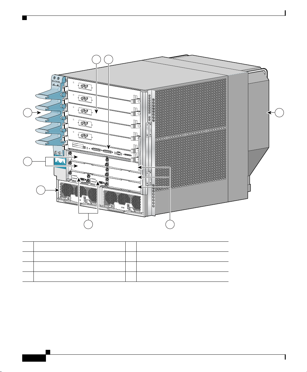
Figure 1-1 Cisco XR 12406 Router—Front View
1 2
8 3
T
C
E
1
J
-
E
T
O
T
L
E
S
S
0
E
T
R
O
L
S
AUX
7
C
ISC
O
12000
S
E
R
IE
S
G
I
G
A
B
I
T
S
W
I
T
C
H
R
O
U
T
E
R
L
L
O
X
C
R
5
4
-
CONSOLE
J
R
K
X
N
I
T
L
I
I
M
G
I
G
A
B
I
T
R
O
U
T
E
P
R
O
C
E
S
S
O
R
6
5
4
1 Line card slots (five) 5 Alarm card slots (two)
2 Route processor slot 6 Power module bays (two)
3 Blower module 7 CSC slots (2)
4 SFC slots (3) 8 Cable management bracket
Cisco XR 12406 Router Installation Guide
1-2
101344
OL-13831-01
Page 17
Chapter 1 Cisco XR 12406 Router Overview
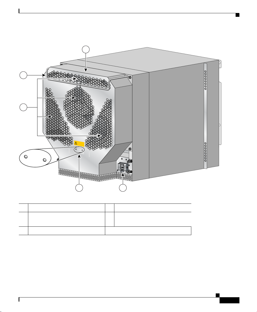
Figure 1-2 Cisco XR 12406 Router—Rear View
1
3
4
H
IG
H
S
P
E
E
D
B
LO
W
E
R
Router Description
2 5
1 Blower module 4 Air exhaust vents
2 Blower module LEDs 5 PDU (behind Blower module; AC
PDU shown)
3 Blower module handle —
With a chassis height of 18.5 inches (46.9 cm), four Cisco XR 12406 Routers can
be installed in a single standard 7-foot (2.15-m) equipment rack.
Cisco XR 12406 Router supports system software downloads for most Cisco XR
IOS software upgrades, which enables you to remotely download, store, and boot
from a new Cisco XR IOS image.
Cisco XR 12406 Router Installation Guide
OL-13831-01
101114
1-3
Page 18

Features
Features
Chapter 1 Cisco XR 12406 Router Overview
Cisco XR 12406 Router has the following key features:
• Route Processor (PRP-2)—Slot 5 (bottom slot) is the recommended slot for
the first route processor. When the router is equipped with a redundant route
processor, it can be installed in any of the five regular line card slots.
• Line Cards—Up to five OC-192 line cards, four if redundant route processors
are installed. These slots support the online insertion and removal (OIR)
feature so installed cards are hot-swappable: A failed card can be removed
and replaced with the router powered on.
• Clock and Scheduler Cards (CSCs) and Switch Fabric Cards (SFCs)—Two
dedicated hot-swappable slots for CSCs; three dedicated hot-swappable slots
for SFCs.
Note When operating your router with a single CSC, the second CSC slot must
have a CSC blank filler (MAS-GSR6-CSCBLNK=) installed to ensure
EMI compliance.
1-4
• Two dedicated alarm card slots (for 1+1 redundancy)
• Alarm and Illumination—Alarm and illumination for operating ranges in the
card cage, clock and scheduler card, and switch fabric card bays.
• Two hot-swappable AC-input power supplies or DC-input power entry
modules (PEMs).
Note When operating your router on a single AC-input power supply or
DC-input PEM, the second power module bay must have a blank filler
(MAS-GSR-PWRBLANK=) installed to ensure EMI compliance.
• All power modules and other field replaceable units (FRUs), except for the
air blower module and the power distribution unit (PDU), can be removed
from the front of the chassis.
• All source power connections are located at the rear of the chassis on the PDU
(see Figure 1-2).
• A new stylish front door hides router cabling and can be installed to open
from the right side or left side to give you total flexibility.
Cisco XR 12406 Router Installation Guide
OL-13831-01
Page 19

Chapter 1 Cisco XR 12406 Router Overview
• Network Equipment Building Systems—Cisco XR 12406 Router complies
with the Network Equipment Building System (NEBS) Criteria Level 3
requirements defined in SR-3580 for flammability, structural, and electronics
compliance.
• Electromagnetic Compatibility and Electrostatic Discharge Compliant— The
Cisco XR 12406 Router complies with emissions, immunity, and
electrostatic discharge (ESD) standards for both product and packaging.
• Bonding and Grounding—Bonding and grounding for safety, circuit
protection, noise currents, reliability, and operations compliance.
• Environmental Monitoring—the Cisco XR 12406 Router complies with
environmental monitoring standards for operating temperature and humidity,
as well as handling temperature and humidity (except for heat dissipation).
• Shock and Vibration—the Cisco XR 12406 Router has been shock- and
vibration-tested for operating ranges, handling, and earthquake standards to
NEBS (Zone 4 per GR-63-Core). These tests have been conducted in
earthquake environment and criteria, office vibration and criteria,
transportation vibration and criteria, and packaged equipment shock criteria.
• Fiber Cable Management—Fiber cable management with support for
high-density fiber Fast Ethernet (FE) ports.
Features
OL-13831-01
• Current 1.275-inch pitch line cards will fit in the line card cage with the
addition of a front panel adapter cover. The line card adapter cover is included
with the 1.275-inch line card.
Cisco XR 12406 Router Installation Guide
1-5
Page 20

Chapter 1 Cisco XR 12406 Router Overview
Physical and Functional Description
Physical and Functional Description
The following are the main components that make up the Cisco XR 12406 Router:
• One route processor with a second (redundant) route processor option
• Up to 5 line cards (4 if there are redundant route processors)
• 2 clock scheduler cards (CSCs)
• 3 switch fabric cards (SFCs)
• 2 alarm cards
• 2 power modules
• Backplane and maintenance bus
• Blower module
• 2 air filters
These components and their functions are described in this section. See Chapter 5,
“Maintaining the Router” for instructions to remove and replace the FRUs.
Route Processor
The route processor for the Cisco XR 12406 Router is the Performance Route
Processor (PRP-2). For detailed information about the Performance Route
Processor, refer to the Cisco document, Performance Route Processor Installation
and Configuration Guide.
The PRP-2 performs the following primary functions:
• Executes routing protocol stacks
• Performs all protocol communications with other routers
• Builds and distributes forwarding information to all line cards
• Uploads the operating system software images to all installed line cards
• Provides out-of-band system console and auxiliary ports and an Ethernet port
• Monitors and manages the power and temperature of system components
Cisco XR 12406 Router Installation Guide
1-6
during power-up
for router configuration and maintenance
such as line cards, power supplies, and fans
OL-13831-01
Page 21

Chapter 1 Cisco XR 12406 Router Overview
The Cisco PRP-2 delivers all these functions with enhanced performance and
capabilities. It also delivers the following feature enhancements (depending on
the software version running):
• Gigabit Ethernet management port
• Hard-drive support (optional part)
• BITS input ports
• 1 GB compact image Flash memory support (optional part)
• Memory scalability up to 4 GB
The PRP-2 communicates with the line cards either through the switch fabric or
through the MBus. The switch fabric connection is the main data path for routing
table distribution as well as for packets that are sent between the line cards and
the PRP-2. The MBus connection allows the PRP-2 to download a system
bootstrap image, collect or load diagnostic information, and perform general,
internal system maintenance operations.
The PRP-2 can be designated as either the Designated System Controller (DSC)
or the Secure Domain router (SDR).
The Designated System Controller (DSC) performs the following functions:
Physical and Functional Description
OL-13831-01
• Implements control plane operations for the chassis
• Monitors temperature and voltage
• Monitors line cards
• On boot up, the first card to become active is designated as the DSC.
The Secure Domain Router (SDR) controls domain security features independent
of any other SDRs on the network.
Cisco XR 12406 Router Installation Guide
1-7
Page 22

Line Cards
Line Cards
Note Refer to the current s software release notes for the most up-to-date list of
Chapter 1 Cisco XR 12406 Router Overview
The Cisco XR 12406 Router is shipped pre-installed with the number and type of
line cards that you ordered. Line cards and route processors can be installed in two
basic combinations to support route processor redundancy and a variety of
physical network media:
• Nonredundant route processor—One route processor and up to five Cisco
XR 12000 series router line cards.
• Redundant route processors—Two route processors and up to four Cisco
XR 12000 series router line cards.
Line cards can be installed in any slot—zero (0) through five (5)—in the card
cage. Slot number 5 is the recommended default route processor slot.
Single-mode and multimode line cards are shown in Figure 1-3.
supported line cards (see “Obtaining Documentation, Obtaining Support, and
Security Guidelines” on page xiv).
1-8
Line cards provide the interfaces to the router’s external physical media. External
connections are made from the front of the chassis to the connectors on the line
card face plates. The line cards communicate with the route processor and
exchange packet data with each other through the switch fabric cards in the switch
fabric and alarm card cage.
Caution Unoccupied card slots in the line card and route processor card cage must have a
blank filler panel installed (12000-WIDE-BLANK=) for electromagnetic
compatibility (EMC) and to ensure proper air flow through the chassis. When the
faceplate of a line card does not completely fill the card slot opening, a narrow
card filler panel must be installed (ACS-GSR16-LCFILL=).
A cable-management bracket attaches to the faceplate of each line card to manage
and organize the network interface cables connected to the individual ports on the
line card.
Line cards installed in the router support online insertion and removal (OIR),
which means you can remove and replace a line card while the router remains
powered on.
Cisco XR 12406 Router Installation Guide
OL-13831-01
Page 23
Chapter 1 Cisco XR 12406 Router Overview
Note For instructions on removing, replacing, and configuring the line cards, see the
configuration note shipped with each line card when ordered as an FRU.
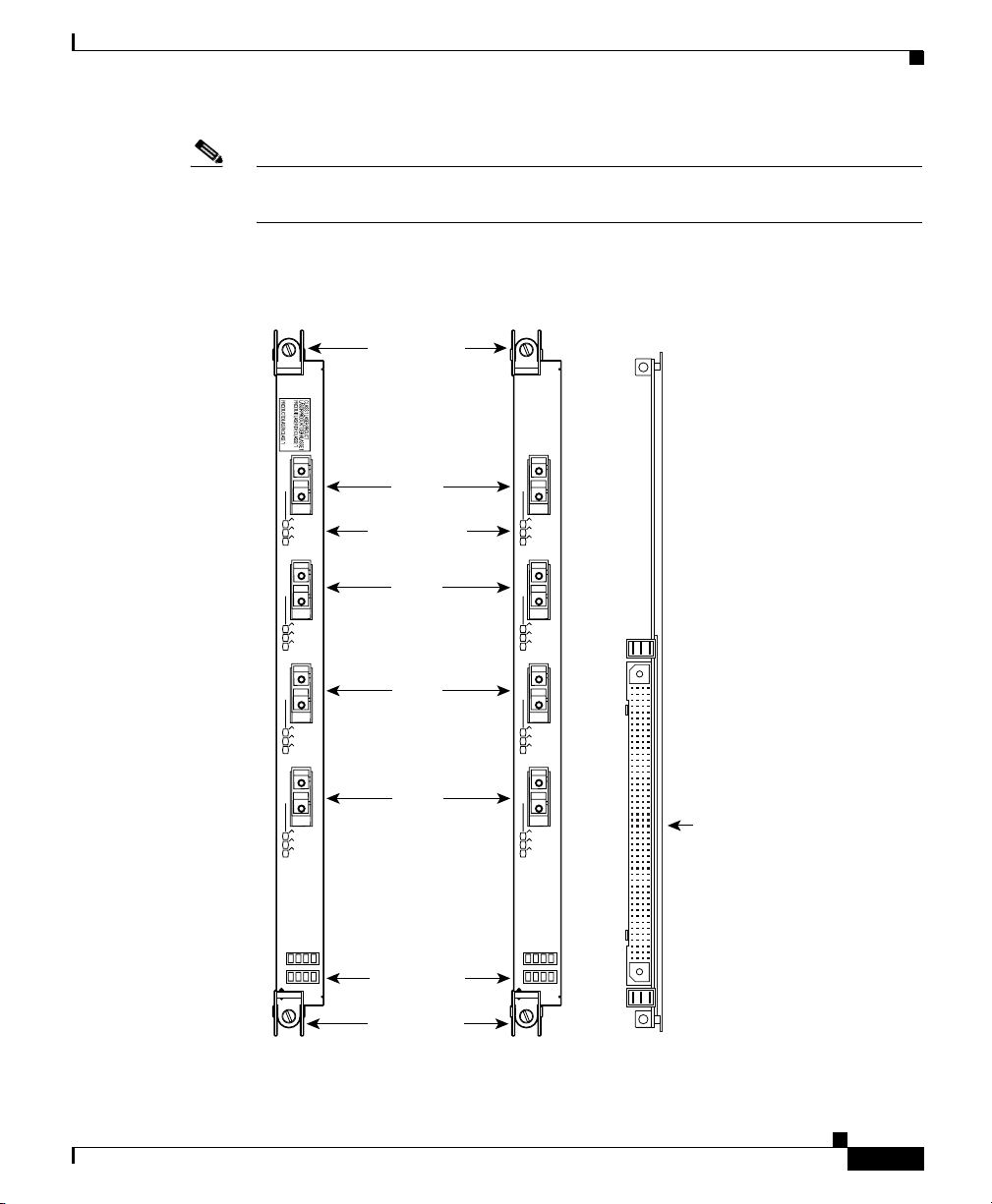
Figure 1-3 Sample Line Cards
Line Cards
Single Mode
0
ACTIVE
CARRIER
RX PKT
1
ACTIVE
CARRIER
RX PKT
2
ACTIVE
CARRIER
RX PKT
3
ACTIVE
CARRIER
RX PKT
Q OC-3/STM-1 SM IR POS
Ejector lever
Port 0
Status LEDs
Port 1
Port 2
Port 3
Multimode
0
ACTIVE
CARRIER
RX PKT
1
ACTIVE
CARRIER
RX PKT
2
ACTIVE
CARRIER
RX PKT
3
ACTIVE
CARRIER
RX PKT
Q OC-3/STM-1 MM POS
160-pin
backplane
signal
connector
OL-13831-01
Alphanumeric
LED display
Ejector lever
Front view Rear view
Cisco XR 12406 Router Installation Guide
H10781
1-9
Page 24

Line Cards
Multigigabit Crossbar Switch Fabric
The Cisco XR 12406 Router switch fabric circuity provides synchronized
gigabit-speed interconnections for the line cards and the route processor. The
switch fabric circuitry resides in five fabric card slots: two for CSCs; three for
SFCs (Figure 1-4).
Figure 1-4 Clock and Scheduler and Switch Fabric Card Bays
T
C
E
1
J
-
E
T
O
T
L
E
S
S
0
E
T
R
O
L
S
X
U
CISCO 12000
G
I
G
A
B
I
T
S
W
I
T
C
S
E
H
R
O
U
T
R
I
E
S
E
R
A
CSC
CSC
Alarm
cards (2)
L
L
O
X
C
R
5
4
-
CONSOLE
J
R
K
X
N
I
T
L
I
I
M
G
I
G
A
B
I
T
R
O
U
T
E
P
R
O
C
E
S
S
O
R
SFC
SFC
SFC
Chapter 1 Cisco XR 12406 Router Overview
57084
Switch Fabric Card Types
The CSCs are installed in the half-width slots labeled CSC 0 and CSC 1 on the
lower left side of the chassis, located directly beneath the route processor and line
card cage and directly above the alarm card bays. The three SFCs are installed in
the half-width slots labeled SFC 0, SFC 1, and SFC 2 on the lower right side of
the chassis.
Note To operate the Cisco XR 12406 Router, you must have at least one CSC card
installed, in addition to SFC and alarm cards.
Cisco XR 12406 Router Installation Guide
1-10
OL-13831-01
Page 25

Chapter 1 Cisco XR 12406 Router Overview
The CSC contains the following functionality:
• System clock—The system clock synchronizes data transfers between line
cards or between the route processor and a line card, through the switch
fabric. In systems with redundant CSCs, the two system clocks are
synchronized so that if one system clock fails, the other clock takes over. The
system clock signal is sent to all line cards, the route processor, and switch
fabric cards.
• Scheduler—The scheduler handles requests from the line cards for access to
the switch fabric. When the scheduler receives a request from a line card for
switch fabric access, the scheduler determines when to allow the line card
access to the switch fabric.
• Switch fabric—The switch fabric carries the user traffic between line cards or
between the route processor and the line cards. The switch fabric card
contains only the switch fabric circuitry and receives scheduling information
and system clock information from the CSC.
The SFC contains only the switch fabric circuitry, which carries user traffic
between line cards or between the route processor and the line cards. The SFC
receives scheduling information and the system clock sent from the CSC.
Line Cards
Switch Fabric Switching Capacity and Router Type
The Cisco XR 12406 Router is based on a 10-Gbps switch fabric, where each CSC
or SFC provides a 10-Gbps full-duplex connection to each line card in the system.
The 10-Gbps switch fabric consists of the Clock and Scheduler Card (product
number GSR6-CSC= for original fabrics, and 12406E-CSC= for enhanced fabric
versions) and the Switch Fabric Card (product number GSR6-SFC= for original
fabrics, and 12406E-SFC= for enhanced fabric versions). The 10-Gbps switch
fabric cards are labeled simply CSC and SFC.
Note You cannot mix 2.5-Gbps switch fabric cards and 10-Gbps switch fabric cards in
a chassis. The router will not operate with a mix of switch fabric card types.
Cisco XR 12406 Router Installation Guide
OL-13831-01
1-11
Page 26

Line Cards
Switch Fabric Redundancy
Equipping the router with two CSCs provides data path, scheduler, and reference
clock redundancy. The interfaces between the line cards and the switch fabric are
monitored constantly. If the router detects a loss of synchronization (LOS), it
automatically activates the data paths of the redundant CSC, and data flows across
the redundant path. The switch to the redundant CSC occurs within 0.5 second,
with little or no loss of data.
Note The enhanced Cisco XR 12406 chassis (XR-12000/6 configured with 12406/120
fabric option) ships with redundant CSC which is required to maintain High
Availability for the system.
Alarm Cards
The Cisco XR 12406 Router has two alarm card slots (Figure 1-5). Each alarm
card performs the following function or indicates the following condition:
• Alarm output
Chapter 1 Cisco XR 12406 Router Overview
1-12
• CSC status
• SFC status
• Alarm card status
• Power source and power entry module status
• Alarm relay contacts
The entire alarm function has been implemented on redundant alarm cards with
OIR maintenance (hot-swappable) functionality.
Cisco XR 12406 Router Installation Guide
OL-13831-01
Page 27
Chapter 1 Cisco XR 12406 Router Overview
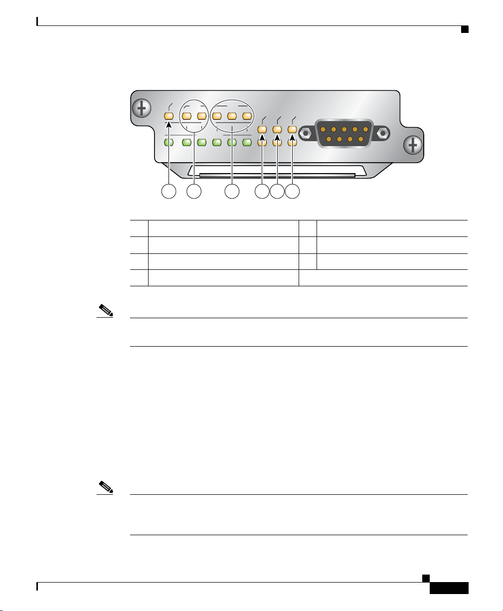
Figure 1-5 Alarm Card Features
Line Cards
1 MBus status LED 5 Major alarm LED
2 CSC status LEDs (two) 6 Minor alarm LED
3 SFC status LEDs (three) – Alarm relay contact connector
4 Critical alarm LED —
Note The Cisco XR 12406 Router must be populated with two alarm cards, to meet
EMI standards.
Alarm Output Function
MBUS
CSC
ENABLED
0
FAI L
01 1 2
SFC
CRITICAL
MAJOR
1 432 5 6
MINOR
ALARM
66170
OL-13831-01
The alarm output function consists of a group of relays, LEDs, and their
associated drivers connected to an output port on the MBus module.
The alarm output function is controlled by the software on the route processor.
When a signal is received from the route processor, the MBus module on the alarm
card activates specific relays to signal an alarm condition. There are three alarm
condition severity levels: critical, major, and minor. The critical, major, and minor
LEDs are paired for redundancy to protect against a single failed LED.
Note Alarm cards for some Cisco XR 12000 series router have both audible and visible
alarm indicators. The alarm card for the Cisco XR 12406 Router provides only
visible alarm indicators as local alerts to unusual conditions in the router.
Cisco XR 12406 Router Installation Guide
1-13
Page 28

Chapter 1 Cisco XR 12406 Router Overview
Line Cards
The IOS XR software running on the route processor determines whether a given
alarm condition is a critical, major, or minor alarm. Typing the show commands
sh gsr table and sh env all will give you the table of limits and current readings
for the LEDs.
Clock and Scheduler Card and Switch Fabric Card Status
The alarm card provides OK and FAIL indications for all clock and scheduler
cards and switch fabric cards in the system. Redundant signals from the fabric
cards are brought out to the LEDs on each alarm card. The alarm card does not
control how these LEDs are used.
The MBus auxiliary power supply consists of a 50W DC-DC power supply and
some current-sharing circuitry. Because the alarm card itself is powered by this
supply, the on-board MBus module can report problems with the supply only
when the redundant alarm card is in the chassis and providing MBus power.
Alarm Card Status
The ENABLED/FAIL pair of LEDs labeled MBUS indicate the status of the alarm
card. The green ENABLED LED indicates that the MBus module on the alarm
card is operating properly. The yellow FAIL LED indicates that the alarm card has
detected an error in itself or with the MBus power supply.
Power Source Monitoring
The alarm card monitors the power modules and signals when there is a condition
outside the normal range of operation. It discloses problems such as the following:
• Power source voltage is not being provided to a component
• A fault exists in the power source or power module
• Output voltage—Voltage monitor signal is outside the allowable range
• Output current—Current monitor signal is outside the allowable range
Cisco XR 12406 Router Installation Guide
1-14
OL-13831-01
Page 29

Chapter 1 Cisco XR 12406 Router Overview
Alarm Relay Contact Connector
The 9-pin D-type alarm relay contact connector on the faceplate of the alarm card
(see Figure 1-5) is used to connect external alarm indication equipment to the
router so that alarm indicator signals in the router can be repeated elsewhere
outside the router.
The pins on this connector are tied directly to the critical, major, and minor alarm
relay contacts (normally open, normally closed, and common). Any event that
causes one of the alarm LEDs on the alarm card faceplate to go on also activates
the corresponding relay contact closure. The relay interface is rated at a maximum
of 2A, 60V, or 50VA, whichever is greater.
Because alarm contact cables are entirely dependent on site-specific
circumstances, alarm connector cables are not available from Cisco. For
information about alarm connector wiring requirements and the pinout for the
alarm connector interface, see the “Alarm Card Alarm Relay Connector
Specifications” section on page A-5.
Power Subsystems
Line Cards
OL-13831-01
The Cisco XR 12406 Router can be powered by either an AC or DC power
subsystem, as described in the following sections:
• AC Power Subsystem, page 1-16
• DC Power Subsystem, page 1-20
• Power Distribution, page 1-24
Note The Cisco XR 12406 Router can be either AC powered or DC powered; the router
cannot accept two different types of power modules at the same time.
Note The enhanced XR 12406 chassis (XR-12000/6 configured with 12406/120 fabric
option) ships with redundant power supply which is required to maintain High
Availability for the system.
Cisco XR 12406 Router Installation Guide
1-15
Page 30
Line Cards
Note A Cisco XR 12406 Router operating from an AC power source can be converted
to operate from a DC power source, and vice versa. The conversion can be done
in the field, but the system must be powered down.
AC Power Subsystem
The AC power subsystem consists of the following system components:
• AC PDU (one)
• AC-input power supplies (one for nonredundant operation; two for redundant
Caution To ensure that the chassis configuration complies with the required power
budgets, use the on-line power calculator. Failure to properly verify the
configuration may result in an unpredictable state if one of the power units fails.
Contact your local sales representative for assistance.
Chapter 1 Cisco XR 12406 Router Overview
operation)
AC PDU
1-16
Facility AC power connects to AC-powered the Cisco XR 12406 Router though
the AC PDU on the chassis rear panel (Figure 1-6).
Cisco XR 12406 Router Installation Guide
OL-13831-01
Page 31

Chapter 1 Cisco XR 12406 Router Overview
Figure 1-6 AC Power Distribution Unit
1
3
Line Cards
4
5
6
OL-13831-01
2
57650
1 Captive screw 4 AC power distribution unit
2 AC power cord receptacle A 5 Guide pin
3 AC power cord receptacle B 6 Blower module connector
Depending on whether the router is configured for nonredundant or redundant
power operation, the router ships with either one or two 14-foot (4.3-m) AC power
cords to connect the PDU to the facility AC power source. AC power cords with
different source AC power plugs are available. (See Figure 2-3 on page 2-16.)
Note For true redundancy, connect each power supply to a separate power circuit
protected by its own circuit breaker.
Cisco XR 12406 Router Installation Guide
1-17
Page 32

Line Cards
AC-Input Power Supply
The AC-input power supply is a removable power module that installs in one of
the bottom two bays on the front of the chassis (see Figure 1-1). These power
modules support the OIR feature and are hot-swappable (Figure 1-7).
Figure 1-7 AC-Input Power Supply
Chapter 1 Cisco XR 12406 Router Overview
3
1
57916
1-18
2 5
4
1 AC-input power supply 4 Release levers captive screws
2 Handle 5 LEDs
3 Power standby switch —
Note When operating your router on a single power module, the second power module
bay must have a blank filler (MAS-GSR-PWRBLANK=) installed to ensure EMI
compliance.
Cisco XR 12406 Router Installation Guide
OL-13831-01
Page 33

Chapter 1 Cisco XR 12406 Router Overview
An AC-input power supply has the following features (see Figure 1-7):
• Original series Cisco XR 12406 routers: A power factor corrector (PFC)
allows the power supply to accept AC power source voltage from an AC
power source operating from 100 to 120 VAC 20-amp service in North
America, and a range of from 185 to 264 VAC 16-amp service in an
international environment.
• Enhanced series Cisco XR 12406 routers: Supports 220 VAC only which
requires 20-amp service in North America, and 16-amp service in an
international environment.
• Each AC-input power supply weighs approximately 14 pounds (6.4 kg), and
can deliver up to 1400 W for original versions, or up to 1950 W for enhanced
versions of the router.
• Each AC-input power supply requires a dedicated 20A service in North
America (16 A international).
• A power standby switch on the faceplate temporarily disables the DC output
power circuitry in the AC-input power supply.
Line Cards
OL-13831-01
Note This switch does not interrupt the incoming AC power in the AC-input
power supply. Portions of the power supply circuitry are still under
AC power as long as AC power is connected to the router.
• A handle is provided for ease in removing and replacing the power supply.
• Captive screws on the power supply ejector levers secure it in the power
supply bay.
• Two LEDs on the faceplate to provide status information. Table 1-1
summarizes the function of these indicators.
Table 1-1 AC-Input Power Supply LED indicators
LED Label Function State Description
AC Input
power
On AC power source is present and is within
specified limits.
Off Power source is not within specified
limits.
Cisco XR 12406 Router Installation Guide
1-19
Page 34

Line Cards
Table 1-1 AC-Input Power Supply LED indicators (continued)
LED Label Function State Description
DC Output
DC Power Subsystem
The DC power subsystem consists of the following system components:
• DC PDU (one)
• DC-input PEMs (one for nonredundant operation; two for redundant
Caution To ensure that the chassis configuration complies with the required power
budgets, use the on-line power calculator. Failure to properly verify the
configuration may result in an unpredictable state if one of the power units fails.
Contact your local sales representative for assistance.
operation)
Power
Chapter 1 Cisco XR 12406 Router Overview
On Power supply is operating normally in a
power-on condition.
Off Power supply is operating in a fault
condition and shutdown has occurred.
DC PDU
1-20
Facility DC power connects to DC-powered routers though the connector blocks
on the DC PDU (Figure 1-8).
Cisco XR 12406 Router Installation Guide
OL-13831-01
Page 35

Chapter 1 Cisco XR 12406 Router Overview
Figure 1-8 DC Power Distribution Unit
1
Line Cards
POWER B
+
GND
4
3
5
POW
ER A
6
+
GND
2
1 Captive screw 4 DC power distribution unit
2 DC power connector block A 5 Guide pin
3 DC power connector block B 6 Blower module connector
57992
OL-13831-01
DC-input power is connected through the DC PDU on the chassis rear panel. The
DC PDU is equipped with two DC power connector blocks. Each DC power
connector block is equipped with three terminal ports. Leads from the DC source
power should be connected to the terminal block. A negative lead is connected to
the top port, a positive lead to the middle port, and a ground lead to the bottom
port.
Cisco XR 12406 Router Installation Guide
1-21
Page 36

Line Cards
DC-Input Power Entry Module
The DC-input PEM (Figure 1-9) is a removable power module that installs in one
of the bottom two bays on the front of the chassis (see Figure 1-1). These power
modules support the OIR feature and are hot-swappable.
Note When operating your router on a single power module, the second power module
bay must have a blank filler (MAS-GSR-PWRBLANK=) installed to ensure EMI
compliance.
Caution The Cisco XR 12406 Router is configured for either AC power or DC power. Do
not mix AC-input power supplies and DC-input PEMs.
Figure 1-9 DC-Input Power Entry Module
Chapter 1 Cisco XR 12406 Router Overview
OUTPUT
OK
INPUT
OK
O
U
T
P
U
T
I
N
P
U
T
O
K
O
K
MISWIRE
M
I
S
W
I
R
E
5
4
4
2
3
1
1 DC-input PEM 4 Captive screws on release levers
2 Handle 5 Air inlet for cooling fan
3 Circuit breaker ON/OFF switch —
62203
1-22
Cisco XR 12406 Router Installation Guide
OL-13831-01
Page 37

Chapter 1 Cisco XR 12406 Router Overview
A DC-input PEM (shown in Figure 1-9) has the following features:
• A circuit breaker switch on the faceplate turns the PEM on and off.
• A handle is provided for ease in removing and replacing the PEM.
• Captive screws on the PEM ejector levers secure it in the PEM bay.
• Three LEDs on the faceplate to provide status information. Table 1-2
summarizes the function of these indicators.
Table 1-2 DC-input PEM LED Indicators
LED Label Color Function
OUTPUT OK Green PEM is operating normally in a powered-on
INPUT OK Green DC power is present at the PEM input and
MISWIRE Amber Indicates input is wired backward at the PDU
Line Cards
condition.
within the specified limits.
input.
OL-13831-01
• Each PEM weighs 10.5 pounds (4.76 kg), and can deliver up to 1400 W at
-48 VDC.
• Each PEM requires a hardwired source DC power cable from the site DC
power source to the DC PDU in the router. The DC power cable leads to the
PDU should be #6 American Wiring Gauge (AWG) high-strand-count wires.
• Only a DC power source that complies with the safety extra-low voltage
(SELV) requirements in UL1950, CSA 950, EN 60950, and IEC950 can be
connected to a PEM.
• The router requires a dedicated 45A DC circuit breaker for the DC power
source. This circuit breaker should protect against short-circuit and
overcurrent faults in accordance with United States National Electrical Code
NFPA 70 (United States), Canadian Electrical Code, part I, CSA C22.1
(Canada), and IEC 364 (other countries).
Note We recommend that you install an uninterruptable power source (UPS) as
a safeguard against power loss.
Cisco XR 12406 Router Installation Guide
1-23
Page 38

Line Cards
Power Distribution
Caution To ensure that the chassis configuration complies with the required power
Chapter 1 Cisco XR 12406 Router Overview
The router chassis backplane distributes -48 VDC power throughout the router
and to all cards in the card cages.
All cards have multiple DC-DC converters that convert the -48 VDC into
+2.5 VDC, +3.3 VDC, +5 VDC, and other voltages as required by the line card.
The DC-DC converters are turned on by the MBus modules under the control of
the route processor and MBus software.
Power for the blower module is supplied directly from the backplane through a
connector in the PDU that passes DC voltage from the backplane to the blower
module. An blower module controller card in the blower module converts
–48 VDC into DC voltage that powers the blower module fans.
budgets, use the on-line power calculator. Failure to properly verify the
configuration may result in an unpredictable state if one of the power units fails.
Contact your local sales representative for assistance.
Blower Module
The Cisco XR 12406 Router is equipped with a blower module to distribute air
within the chassis. The blower module is located on the rear of the chassis (see
Figure 1-2). The blower module draws room air into the chassis through two air
filters on the side of the chassis, pulls the air through the chassis card cages, and
expels it through exhaust vents on the back of the blower module (Figure 1-10).
Caution Exhaust from other equipment vented directly into the router air inlet may cause
overheating. The front, back, and sides of the router must remain unobstructed to
ensure adequate air flow and prevent overheating inside the chassis. Allow
sufficient air flow by maintaining 6 inches (15.24 cm) of clearance at both the
inlet and exhaust openings on the chassis.
Cisco XR 12406 Router Installation Guide
1-24
OL-13831-01
Page 39

Chapter 1 Cisco XR 12406 Router Overview
If the air temperature inside the route processor and line card cage rises, the
system environmental monitor shuts down all internal power to prevent equipment
damage from excessive heat.
If the system detects that one of three fans within a blower module has failed, it
displays a warning message on the console screen. If multiple fans fail, the system
shuts down to prevent equipment damage.
Figure 1-10 Internal Air Flow—Top View
Air exhaust Air exhaust
Blower module
Line Cards
Room air
OL-13831-01
Top view
Room air
Air filter
Cisco XR 12406 Router Installation Guide
57649
1-25
Page 40

Line Cards
The two LEDs on the blower module provide a visual indication of blower module
status. Both LEDs are visible on the blower module from the rear of the chassis.
• OK—Left LED; Green. When on, this LED indicates that the blower module
is operating normally. This LED should come on as soon as the blower
module is installed and receives power from the backplane connector.
• Fail—Right LED; Red. The red LED should remain off during normal
operation. If the red LED is on, the system has detected a fan failure or other
fault in the blower module. Replace the existing blower module with a spare.
Chassis Backplane and Maintenance Bus
All of the card cages for the Cisco XR 12406 Router are tied together electrically
through a passive system backplane in the back of the chassis. Nearly all of the
wiring and circuitry in the chassis is contained within or connected to the chassis
backplane. The chassis backplane distributes DC power to all of the cards in the
chassis as well as the blower module, and provides the physical communication
pathway between cards, both for network data and system communication across
the internal system maintenance bus (MBus).
Chapter 1 Cisco XR 12406 Router Overview
1-26
The maintenance bus and MBus modules manage the maintenance functions of
the system. The MBus is integrated into the backplane and consists of two
separate buses, providing MBus redundancy.
Both MBus networks are linked to all the following items:
• Route processor and line cards
• CSCs, SFCs, and alarm cards
• Power modules
• Blower module
The MBus module located on each component communicates over the MBus and
is powered by DC voltage directly from the alarm card. The MBus performs the
functions of power-up/down control for each component, component (device)
discovery, code download, diagnostics, and environmental monitoring and
alarms.
Cisco XR 12406 Router Installation Guide
OL-13831-01
Page 41

Chapter 1 Cisco XR 12406 Router Overview
Power-on and Power-off Control
Each MBus module directly controls the DC-DC converters on the component on
which it is mounted, based on commands the component receives from its
on-board EPROM and from the route processor. Each MBus module is tied
directly to DC voltage from the alarm card.
When power is applied to the router, all MBus modules immediately power on.
The MBus modules on the route processor and CSC immediately turn on the
DC-DC converter, powering up the respective card. The line card MBus module
waits to power on the line card until it receives a command from the route
processor.
Device Discovery
The route processor uses the MBus to detect the system configuration. The route
processor sends a message over the MBus requesting identity information from
all installed devices. The responses provide component type, as well as slot
numbers for the line cards, CSCs, SFCs, and alarm cards.
Line Cards
Code Download
Diagnostics
OL-13831-01
A portion of the line card operating software can be downloaded from the route
processor to the line card over the MBus. Because the MBus is relatively slow
compared to the switch fabric, only enough code is downloaded to the line card
for it to access the switch fabric and complete the download process.
The diagnostic software image is downloaded from the route processor to the line
card during the test sequence.
Cisco XR 12406 Router Installation Guide
1-27
Page 42

Line Cards
Environmental Monitoring and Alarms
The MBus module on each component monitors the environment of that
component as follows:
• Line cards and the route processor are monitored for temperature by two
temperature sensors mounted on each card. The MBus module makes voltage
adjustments through software for the +2.5 VDC, +3.3 VDC, and +5 VDC
DC-DC converters.
• Clock and scheduler cards and switch fabric cards are monitored for
temperature by two temperature sensors mounted on each card. The MBus
module makes voltage adjustments through software for the +2.5 VDC and
+3.3 VDC converters.
• The MBus module on the alarm card makes voltage adjustments for +5 VDC.
• Environmental monitoring includes voltage monitoring, temperature
monitoring, and sensing for the blower module fans.
Chapter 1 Cisco XR 12406 Router Overview
1-28
Cisco XR 12406 Router Installation Guide
OL-13831-01
Page 43

Chapter 1 Cisco XR 12406 Router Overview
Air Filters
The Cisco XR 12406 Router is equipped with two user-serviceable air filters
(Figure 1-11).
Figure 1-11 Air Filter Locations
T
C
E
1
J
-
E
T
O
T
L
E
S
S
0
E
T
R
O
L
S
AUX
C
ISC
O
12000
S
E
R
IE
S
G
I
G
A
B
I
T
S
W
I
T
C
H
R
O
U
T
E
R
L
L
O
X
C
R
5
4
-
CONSOLE
J
R
K
X
N
I
T
L
I
I
M
G
I
G
A
B
I
T
R
O
U
T
E
P
R
O
C
E
S
S
O
R
Line Cards
OL-13831-01
57678
The air filters are located on the right of the front side of the chassis. The air filters
are housed behind a door that is spring-loaded in the closed position.
Caution Air filters should be clean when the router is operating. Inspect and clean the air
filters once a month, more often in dusty environments.
Do not run the router without the air filters installed. You should inspect and clean
the air filters once a month, more often in dusty environments.
Cisco XR 12406 Router Installation Guide
1-29
Page 44

Line Cards
Cable-Management System
The Cisco XR 12406 Router cable-management system organizes the interface
cables entering and exiting the system, keeping them free of sharp bends and out
of the way.
Caution Excessive bending in an interface cable can degrade performance.
The cable-management system (Figure 1-12) consists of the following
components:
• One vertical cable-management bracket on the chassis
• One line card cable-management bracket on each line card
When you face the front of the router chassis, the chassis cable-management
bracket is installed on the left side of the chassis, adjacent to the line card and
route processor card cage. The chassis cable-management bracket organizes the
line card and route processor cables to keep them from binding, and it eliminates
interference when access to the front of the chassis is necessary for maintenance
and reading the LEDs.
A line card cable-management bracket attaches to each line card with captive
screws. Cable ties on the bracket hold the network interface cables in place, keep
the cables organized relative to their assigned connectors, and manage the bend
radius of each cable as it enters the connector on the line card.
Chapter 1 Cisco XR 12406 Router Overview
1-30
On line cards with multiple ports, the line card cable-management bracket keeps
the network interface cables organized when your remove and replace the line
card. You can unplug the network interface cables from their connectors on the
line cards and leave the cables bundled in the line card cable-management bracket
while you remove the bracket from the line card. That way, when you replace the
line card, the network interface cables are already aligned with the correct line
card cable connectors.
Cisco XR 12406 Router Installation Guide
OL-13831-01
Page 45

Chapter 1 Cisco XR 12406 Router Overview
Figure 1-12 Chassis Cable-Management System
T
C
E
1
J
-
E
T
O
T
L
E
S
S
0
E
-
T
R
O
L
S
X
U
C
IS
C
O
1
2
0
0
GIGABIT SWITCH ROUTER
A
CONSOLE
0
S
E
R
I
E
S
L
L
O
X
C
R
5
4
J
R
K
X
IN
T
L
I
I
M
Line Cards
GIGABIT ROUTE PROCESSOR
OL-13831-01
101833
Cisco XR 12406 Router Installation Guide
1-31
Page 46

Line Cards
Field-Replaceable Units
The field-replaceable units (FRUs) for the Cisco XR 12406 Router include the
following units:
Note For information on ordering FRUs, contact a customer service representative (see
the section titled Obtaining Documentation, Obtaining Support, and Security
Guidelines on page xiv).
• Route processor
• Line cards
• CSCs
• SFCs
• Alarm cards
• PDU:
–
For AC powered systems, AC PDU
–
For DC-powered systems, DC PDU
Chapter 1 Cisco XR 12406 Router Overview
1-32
• Power modules:
–
For AC-powered systems, AC-input power supplies
–
For DC-powered systems, DC-input PEMs
• AC power cords (for AC powered systems)
• Blower module
• Air filters
• Chassis cable-management bracket
Cisco XR 12406 Router Installation Guide
OL-13831-01
Page 47

Chapter 1 Cisco XR 12406 Router Overview
Upgrading a Cisco 12000 Series Router to a Cisco XR 12000 Series Router
Upgrading a Cisco 12000 Series Router to a Cisco XR
12000 Series Router
A Cisco XR 12000 series router can be upgraded to a Cisco XR 12406 Router by
updating the line cards and software images. For information on this process,
including supported line cards and software upgrade procedures, please refer to
the Cisco document, Upgrading a Cisco 12000 Series Router from Cisco IOS
Software to Cisco IOS XR Software.
Technical Specifications
For technical specifications and compliance information for the Cisco XR 12406
Router, see Appendix A, “Cisco XR 12406 Router Technical Specifications and
Warnings.”
OL-13831-01
Cisco XR 12406 Router Installation Guide
1-33
Page 48

Technical Specifications
Chapter 1 Cisco XR 12406 Router Overview
1-34
Cisco XR 12406 Router Installation Guide
OL-13831-01
Page 49
CHAPTER
2
Preparing for Installation
This chapter provides specific information about preparing your site for the
installation of the Cisco XR 12406 Router. The following sections are included in
this chapter:
• Tools and Equipment, page 2-2
• Safety and Compliance, page 2-2
• Safety with Electricity, page 2-8
• Installation Site Requirements, page 2-9
• Unpacking and Repacking the Router, page 2-21
• Transporting a Cisco XR 12000 Series Router, page 2-22
• Site Preparation Checklist, page 2-22
Before installing a Cisco XR 12406 Router, you should have the following
information:
• Power and cabling requirements that must be in place at your installation site
OL-13831-01
• Equipment you will need to install the router
• Environmental conditions your installation site must meet to maintain normal
operation
Note Do not unpack the router until you are ready to install it.
Cisco XR 12406 Router Installation Guide
2-1
Page 50

Tools and Equipment
Tools and Equipment
The Cisco XR 12406 Router can be installed with a minimum number of tools.
The following tools are required:
• 1/4-inch and 3/16-inch flat-blade screwdrivers
• 9/16-inch wrench
• 10-mm wrench (either open-end or socket)
• 2-mm allen wrench
• ESD-preventive wrist strap
• Antistatic mat
• Tape measure
• Wire cutters
• Pliers
Chapter 2 Preparing for Installation
Safety and Compliance
The following guidelines help to ensure your safety and protect the equipment.
This section does not include every potentially hazardous situation, so be alert.
• General Safety Guidelines, page 2-3
• Compliance and Safety Information, page 2-4
• Laser Safety, page 2-7
• Lifting Guidelines, page 2-7
Cisco XR 12406 Router Installation Guide
2-2
OL-13831-01
Page 51

Chapter 2 Preparing for Installation
General Safety Guidelines
The following are some general safety guidelines you should be aware of when
installing or maintaining the Cisco XR 12406 Router.
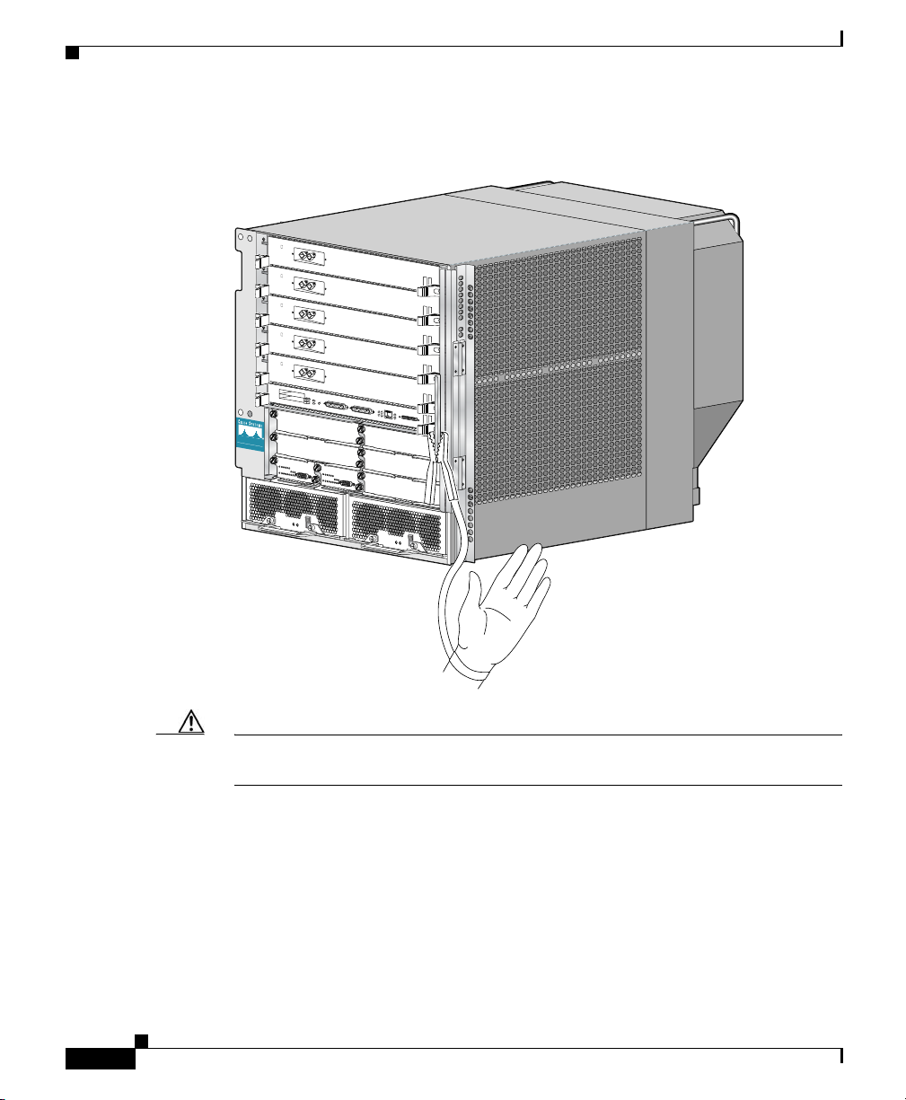
• Never attempt to lift an object that might be too heavy for you to lift by
yourself.
Caution Do not attempt to lift the chassis by the blower module handle. The
blower module handle is intended for lifting the blower module only
when it is disconnected from the chassis.
• Always disconnect the power source and unplug all power cables before
lifting, moving, or working on the router.
• Keep the work area clear and dust free during and after installation.
• Keep tools and router components away from walkways and equipment rack
aisles.
• Do not wear loose clothing, jewelry (including rings and chains), or other
items that could get caught in the router.
Safety and Compliance
OL-13831-01
• Fasten your tie or scarf and sleeves.
• Cisco equipment operates safely when it is used in accordance with its
electrical ratings and product usage instructions.
• Do not work alone if potentially hazardous conditions exist.
• Always unplug the power cables when performing maintenance or working
on the router, unless the replacement part is hot swappable and designed for
online insertion and removal (OIR).
• The installation of the router should be in compliance with national and local
electrical codes: in the United States, National Fire Protection Association
(NFPA) 70, United States National Electrical Code; in Canada, Canadian
Electrical Code, part I, CSA C22.1; in other countries, International
Electrotechnical Commission (IEC) 364, part 1 through part 7.
• Before installing, configuring, or maintaining the router, review the safety
warnings listed in the Regulatory Compliance and Safety Information for the
Cisco 12000 Series Router that accompanied your router.
Cisco XR 12406 Router Installation Guide
2-3
Page 52

Safety and Compliance
Chapter 2 Preparing for Installation
• A Cisco XR 12406 Router with an AC power distribution unit (PDU) and
AC-input power supplies are shipped with AC power cords equipped with
three-wire electrical grounding-type plugs that will fit into only a
grounding-type power outlet. This is a safety feature. The equipment
grounding should be in accordance with local and national electrical codes.
• A Cisco XR 12406 Router with a DC PDU and DC-input power entry
modules (PEMs) require an external 45A DC circuit breaker for each DC
power source. This circuit breaker should protect against short-circuit and
overcurrent faults in accordance with United States National Electrical Code
NFPA 70 (United States), Canadian Electrical Code, part I, CSA C22.1
(Canada), and IEC 364 (other countries).
• Only a DC power source that complies with the safety extra-low voltage
(SELV) requirements in UL 1950, CSA-C22.2 No. 950, EN60950, ACA
TS001, AS/NZS 3260, and IEC60950 should be connected to a Cisco XR
12406 Router with DC PDU and DC-input PEMs.
• A Cisco XR 12406 Router configured with DC-input PEMs should be
installed in a restricted access area in accordance with Articles 110-16,
110-17, and 110-18 of the National Electric Code, ANSI/NFPA 70.
• A Cisco XR 12406 Router configured with a DC PDU shall have a readily
accessible disconnect device incorporated in the fixed wiring.
Compliance and Safety Information
The Cisco XR 12406 Router is designed to meet the regulatory compliance and
safety approval requirements. Refer to the Regulatory Compliance and Safety
Information for the Cisco 12000 Series Router if you require additional
compliance information (seethe “Obtaining Documentation, Obtaining Support,
and Security Guidelines” section on page -xiv for site information).
Cisco XR 12406 Router Installation Guide
2-4
OL-13831-01
Page 53

Chapter 2 Preparing for Installation
Preventing Electrostatic Discharge Damage
Electrostatic discharge (ESD) damage to circuit boards can occur if proper
grounding is not established. The boards can produce intermittent or complete
failures if they are mishandled.
When handling circuit boards, observe the following guidelines to prevent ESD
damage:
• Always use an ESD-preventive ankle or wrist strap and ensure that the strap
makes adequate contact with your skin.
• The ankle or wrist strap protects equipment from ESD voltages on the body
only; ESD voltages on clothing can still cause damage to electronic
components.
Attaching an ESD-Preventive Strap
Attach an ESD antistatic strap to your body and to an open metal part of the
chassis on the Cisco XR 12406 Router (Figure 2-1).
Safety and Compliance
OL-13831-01
Cisco XR 12406 Router Installation Guide
2-5
Page 54
Safety and Compliance
Chapter 2 Preparing for Installation
Figure 2-1 Attaching an ESD-Preventive Strap to the Cisco XR 12406
Router Chassis
T
C
E
1
J
-
E
T
O
T
L
E
S
S
0
E
T
R
O
L
S
X
U
A
C
IS
C
O
1
2
0
0
0
S
E
R
I
E
S
G
I
G
A
B
I
T
S
W
I
T
C
H
R
O
U
T
E
R
L
L
E
O
L
X
C
O
R
S
5
N
4
-
O
J
C
R
K
X
N
I
T
L
I
I
M
G
I
G
A
B
I
T
R
O
U
T
E
P
R
O
C
E
S
S
O
R
57082
2-6
Caution Periodically check the resistance value of the antistatic wrist strap. The resistance
measurement should be between 1 and 10 megohms.
Cisco XR 12406 Router Installation Guide
OL-13831-01
Page 55

Chapter 2 Preparing for Installation
Laser Safety
Single-mode Cisco XR 12000 series router line cards are equipped with lasers.
The lasers emit invisible radiation. Do not stare into open line card ports. Observe
the following warning to prevent eye injury:
Safety and Compliance
Warning
Avoid exposure to laser radiation. Do not stare into an open aperture, because
invisible laser radiation may be emitted from the aperture when a cable is not
inserted in the port.
Lifting Guidelines
A fully configured Cisco XR 12406 Router weighs approximately 205 pounds (93
kg). Before you install the router, ensure that your site is properly prepared so that
you will not have to move the router later to accommodate power source and/or
network connections.
Caution To prevent damage, never attempt to lift or tilt the router chassis using the handles
on the blower module or line cards. These handles do not support the weight of
the chassis.
Whenever you lift any heavy or awkward equipment, follow these precautions to
avoid injury to yourself or damage to the equipment:
• When using moving equipment, such as a safety hand truck, pallet jack, or
• Have a second person help lift the equipment; avoid lifting the equipment
forklift to move the equipment to another location, use only moving
equipment that is capable of preventing the router from tipping.
alone.
OL-13831-01
• Ensure that your footing is solid; balance the weight of the object between
your feet.
• Lift the equipment slowly; never move suddenly or twist your body as you
lift.
Cisco XR 12406 Router Installation Guide
2-7
Page 56

Safety with Electricity
• Keep your back straight and lift with your legs, not your back. If you must
bend down to lift the equipment, bend at the knees, not at the waist, to reduce
the strain on your lower back muscles.
• Always disconnect all external cables before lifting or moving the router.
Safety with Electricity
Most Cisco XR 12406 router field replaceable units (FRUs) support online
insertion and removal (OIR), which means they can be removed and installed
(hot-swapped) while the router remains powered on.
• Line cards, switch fabric cards (SFCs), alarm cards, and the blower module
are hot-swappable.
• Power modules, clock and scheduler cards (CSCs), and RPs also support OIR,
but are hot-swappable only when the system is equipped with two power
modules, two CSCs, or two RPs, respectively.
• The power distribution unit (PDU) does not support OIR.
Chapter 2 Preparing for Installation
2-8
Cisco XR 12406 Router Installation Guide
OL-13831-01
Page 57

Chapter 2 Preparing for Installation
Installation Site Requirements
This section provides the site requirement guidelines that you must consider
before installing a Cisco XR 12406 Router:
Rack-Mounting Guidelines
Before installing a Cisco XR 12406 Router in a rack, consider the general
rack-mounting guidelines in the following sections.
Types of Equipment Racks
A Cisco XR 12406 Router can be mounted in most two-post, four-post, or
telco-type 19-inch equipment racks that comply with the Electronics Industries
Association (EIA) standard for equipment racks (EIA-310-D). The rack must
have at least two posts with mounting flanges on which to mount the router
chassis. The distance between the center lines of the mounting holes on the two
mounting posts must be 18.31 inches ± 0.06 inch (46.50 cm ± 0.15 cm).
Installation Site Requirements
OL-13831-01
Cisco XR 12406 Router Installation Guide
2-9
Page 58

Installation Site Requirements
Equipment Dimensions and Site Layout
Figure 2-2 shows the footprint and outer dimensions of the chassis for the Cisco
XR 12406 Router.
Figure 2-2 Chassis Outer Dimensions and Footprint
23.137 in.
Chapter 2 Preparing for Installation
17.234 in.
2-10
30.877 in.
7.740 in.
Cisco XR 12406 Router Installation Guide
18.950 in.
57090
OL-13831-01
Page 59

Chapter 2 Preparing for Installation
To help maintain trouble-free operation, consider the following precautions when
planning your rack installation:
• The site of the rack must include provisions for source AC or DC power,
grounding, and network interface cables.
• For the actual installation, allow sufficient space to work around the rack. You
will need at least 3 feet adjacent to the rack to move, align, and insert the
chassis. You need at least 2 feet in front of the chassis to insert power
modules.
• Maintain at least 24 inches (61 cm) of clearance in front of and behind the
chassis for maintenance after installation.
• To mount the router between two posts or rails, the usable aperture (the width
between the inner edges of the two mounting flanges) must be at least 17.5
inches (44.5 cm).
• For the enhanced model of the Cisco XR 12406 Router, the mounting rails on
a 4-post rack must be recessed no more than 1.5 inches for the front door to
fully open and close and to provide adequate room for cable routing.
• The height of the Cisco XR 12406 Router is 18.5 inches (46.9 cm). Most
7-foot (2.15-m) equipment racks will accommodate four Cisco XR 12406
Routers. Allow sufficient space in the rack for the router.
• When fully populated with cards, a Cisco XR 12406 Router can weigh as
much as 205 pounds (93 kg). If you use a telco-style rack, the weight of the
chassis is cantilevered off of the two rack posts. Ensure that the weight of the
router does not make the frame unstable. Be sure that the frame is bolted to
the floor and is secured to the building structure, either to wall or to overhead
brackets.
Installation Site Requirements
OL-13831-01
• Do not route cables in such a way as to disrupt movement in front of or behind
the rack. To avoid noise interference in network interface cables, do not route
them directly across or along power cables. Use appropriate strain-relief
methods to protect cables and equipment connections.
• Install and use the cable-management brackets included with the router to
keep cables organized and out of the way of line cards, power modules, and
blower modules. Consider the equipment and cabling that is already installed
in the rack. Ensure that cables from other equipment do not impair access to
the card cages, requiring you to disconnect cables unnecessarily to perform
equipment maintenance or upgrades.
Cisco XR 12406 Router Installation Guide
2-11
Page 60

Installation Site Requirements
Ventilation
Note Warm air is exhausted from the rear of the chassis. Maintain 6 inches (15.24 cm)
Chapter 2 Preparing for Installation
The blower module is mounted at the rear of the chassis; air flow to the air filters
and blower module should not be blocked.
of clearance at both the inlet and exhaust openings on the chassis to allow
sufficient air flow.
• When placing multiple a Cisco XR 12406 Router in the same rack, ensure that
there is sufficient ventilation to accommodate the routers.
• Equipment located near the bottom of the rack can generate excessive heat
that is drawn upward and into the intake ports of equipment above, possibly
leading to overheating.
• The heated exhaust air from other equipment can enter the inlet air vents and
cause overheating inside the router.
• A ventilation system that is too powerful in an enclosed rack can also prevent
cooling by creating negative air pressure around the chassis and redirecting
the air away from the air intake vent. If necessary, operate the router with the
rack door open or in an open rack.
2-12
• The correct use of baffles inside an enclosed rack can assist in cooling the
router.
Cisco XR 12406 Router Installation Guide
OL-13831-01
Page 61

Chapter 2 Preparing for Installation
Environmental Guidelines
This section offers guidelines for operating a Cisco XR 12406 Router in various
environments. The following environmental considerations are discussed:
• Airflow
• Temperature and humidity
Airflow
The air circulation system for a Cisco XR 12406 Router consists of one blower
module mounted at the rear of the chassis. The blower module maintains
acceptable operating temperatures for the internal components by drawing
cooling air in through replaceable air filters located on the right side of the
chassis. Air circulates through the card cage and exhausts at the rear of the
chassis.
Observe the following guidelines when selecting a site in which to install a Cisco
XR 12406 Router:
Installation Site Requirements
OL-13831-01
• Dust free—The site should be as dust free as possible. Dusty environments
can clog the air filter or power supply intake vents, reducing the cooling air
flow through the router. This can cause an over temperature condition in the
router.
• Air flow—Allow sufficient air flow by maintaining a minimum of 6 inches
(15.24 cm) of clearance at both the inlet and exhaust openings on the chassis
and the power modules. If the air flow is blocked or restricted, or if the inlet
air is too warm, an over temperature condition can occur within the router.
Under extreme conditions, the environmental monitoring system shuts down
the power to protect the router components.
Cisco XR 12406 Router Installation Guide
2-13
Page 62

Installation Site Requirements
Temperature and Humidity
The operating environmental site requirements are listed in Appendix A, “Cisco
XR 12406 Router Technical Specifications and Warnings.” The temperature and
humidity ranges listed are those within which the Cisco XR 12406 Router will
continue to operate. You can maintain normal operation by anticipating and
correcting environmental irregularities before they approach critical values.
The environmental monitoring functionality built into the Cisco XR 12406 Router
protects the system and components from potential damage from overvoltage and
over temperature conditions. To assure normal operation and avoid maintenance
difficulty, plan and prepare your site before you install the router.
Power Connection Guidelines
A Cisco XR 12406 Router can be configured with either an AC-input power
subsystem or a DC-input power subsystem. Site power requirements differ
depending on which source power scheme is used. Follow these precautions and
recommendations when planning power connections to the router:
Chapter 2 Preparing for Installation
2-14
• Check the power at your site before installation and periodically after
installation to ensure that you are receiving clean power.
• If necessary, install a power conditioner.
• Install proper grounding to avoid damage from lightning and power surges.
Note When operating your router on a single power module, the second power
module bay must have a blank filler (MAS-GSR-PWRBLANK=)
installed to ensure EMI compliance.
Cisco XR 12406 Router Installation Guide
OL-13831-01
Page 63

Chapter 2 Preparing for Installation
Power Connection Guidelines for AC-Powered Routers
When the Cisco XR 12406 Router operates with an AC PDU, observe these
guidelines:
• Original series Cisco XR 12406 routers: A power factor corrector (PFC)
allows the power supply to accept AC power source voltage from an AC
power source operating from 100 to 120 VAC 20-amp service in North
America, and a range of from 185 to 264 VAC 16-amp service in an
international environment.
• Enhanced series Cisco XR 12406 routers: Supports 220 VAC only which
requires 20-amp service in North America, and 16-amp service in an
international environment.
• Use only the 14-foot (4.3-meter) AC power cords shipped with the system.
• Provide a dedicated power source with its own circuit breaker for each
AC-input power supply installed in the router.
• Install an uninterruptable power source where possible.
Power plug types used in North America, Australia, and Europe are described in
Table 2-1 and shown in Figure 2-3.
Installation Site Requirements
OL-13831-01
Table 2-1 AC-Input Power Cord International Options
Label Description Cisco Product Number
United States 110 VAC (original
CAB-GSR6-US
Cisco XR 12000 series
routers)
United States 220 VAC (enhanced
CAB-GSR6-220V-US
Cisco XR 12000 series
routers)
North America 20A, 250 VAC CAB-GSR16-US=
Australia, New Zealand 15A, 250 VAC CAB-GSR16-AU=
Europe, Argentina, Brazil 16A, 250 VAC CAB-GSR16-EU=
Italy 16A, 250 VAC CAB-GSR16-IT=
United Kingdom 13A, 250 VAC (13A
CAB-GSR16-UK=
replaceable fuse)
Cisco XR 12406 Router Installation Guide
2-15
Page 64

Installation Site Requirements
Figure 2-3 AC Power Plugs
Chapter 2 Preparing for Installation
North American plug
L6-20 20A
Italian plug
CEI 23-16/VII 16A
Australian plug
AS 3112 15A
United Kingdom plug
European plug
CEE 7/7 16A
BS 1363 13A
Power Connection Guidelines for DC-Powered Routers
When the Cisco XR 12406 Router operates with a DC PDU, observe these
guidelines:
• A Cisco XR 12406 Router configured with a DC PDU and DC-input PEMs
require a dedicated 45A DC circuit breaker for each DC power source. This
circuit breaker protects against short-circuit and overcurrent faults in
accordance with United States National Electrical Code NFPA 70 (United
States), Canadian Electrical Code, part I, CSA C22.1 (Canada), and IEC 364
(other countries).
• DC power cable leads should be #6 American Wiring Gauge (AWG)
high-strand-count wire.
57648
2-16
• Provide a dedicated power source for each power entry module installed in
the router.
• Install an uninterruptable power source where possible.
Cisco XR 12406 Router Installation Guide
OL-13831-01
Page 65

Chapter 2 Preparing for Installation
Grounding Connections
Before you connect power or turn on your Cisco XR 12406 Router, you must
provide an adequate system ground for the router. The equipment grounding
should be in accordance with local and national electrical codes.
For installations other than in a network equipment building system (NEBS)
environment, you may chose to rely on the safety earth ground connection
supplied via the International Electrotechnical Commission (IEC) 320 inlets for
AC-powered units and the main terminal block ground connection for
DC-powered units.
• On Cisco XR 12406 Routers configured for AC-input operation, the AC PDU
is equipped with two three-wire electrical grounding-type connectors that
accept three-wire, grounding-type AC power cords such as the power cords
shipped with the router. This is a safety feature.
• On Cisco XR 12406 Routers configured for DC-input operation, the DC PDU
is equipped with two DC power connector blocks, each with wire-connection
terminals for connecting the negative lead (top terminal), the positive lead
(middle terminal), and the ground lead (bottom terminal). This is a safety
feature.
Installation Site Requirements
OL-13831-01
Note The Cisco XR 12404 Router grounding architecture conforms to the
DC-I (DC-isolated) method of grounding as described in Telcordia
GR-1089-CORE. A DC-I architecture means that there is no connection
between the DC return terminal and the frame ground. DC return and
frame ground are isolated from one another at the router.
If the router is installed in a NEBS environment, we strongly recommend that you
connect the central office ground system or interior equipment grounding system
to the supplemental bonding and grounding point on the router chassis. This
grounding point consists of three threaded inserts is located on the side of the
chassis near the back of the chassis (Figure 2-4). It is also referred to as the NEBS
bonding and grounding receptacle, and is intended to satisfy the Telcordia NEBS
requirements for supplemental bonding and grounding connections.
Cisco XR 12406 Router Installation Guide
2-17
Page 66

Installation Site Requirements
Figure 2-4 Supplemental Bonding and Grounding Port for NEBS
C
I
S
C
O
1
2
0
0
0
S
E
R
I
E
S
G
I
G
A
B
I
T
S
W
IT
C
H
R
O
U
T
E
R
Use a cable lug with two holes at 0.63" (16 mm) centers to connect to the chassis
with two 6.3 mm (M6) screws as shown in Figure 2-5. The lug can be ordered
from Cisco (Part Number 32-0607-01).
Chapter 2 Preparing for Installation
Compliance
T
C
E
1
J
-
E
T
O
T
L
E
S
S
E
-0
T
R
O
L
S
X
U
A
L
L
E
O
L
X
C
O
R
S
5
N
4
-
O
J
C
R
K
X
IN
T
L
II
M
G
I
G
A
B
I
T
R
O
U
T
E
P
R
O
C
E
S
S
O
R
57744
2-18
Figure 2-5 Cable Lug
End View
0.48
Ø 0.267
2 holes
0.08
Cisco XR 12406 Router Installation Guide
All measurements in inches
2.24
Crimp area
0.25 0.370.63
25527
OL-13831-01
Page 67

Chapter 2 Preparing for Installation
The dual-hole lug is crimped onto a grounding wire of a wire size and length
determined by your router location and facility environment. The crimping tool
shown in Figure 2-6 is a standard crimping tool obtainable from any normal
hardware source.
Figure 2-6 Crimping the Lug
1
Installation Site Requirements
OL-13831-01
57808
2
1
Place ground wire in the lug
Note The three threaded inserts that make up the grounding receptacle are set in a
2
Crimp the lug
triangle so that you can choose any two of the three holes to attach the lug and
grounding cable.
Cisco XR 12406 Router Installation Guide
2-19
Page 68

Installation Site Requirements
Site Wiring
This section presents site wiring guidelines for setting up the plant wiring and
cabling at your site. When planning the location of the new system, consider the
following:
• Electromagnetic interference (EMI)
• Distance limitations for signaling and unshielded conductors
Electromagnetic Interference
EMI can occur between the signals on the wires and external or ambient EMI
fields when the wires are run for any significant distance. Bad wiring practice can
result in radio interference emanating from the plant wiring.
Chapter 2 Preparing for Installation
Warning
Strong EMI, especially when it is caused by lightning or radio transmitters, can
destroy the signal drivers and receivers in the Cisco XR 12406 Router, can
create an electrical hazard by conducting power surges through lines, and can
damage the equipment.
To predict and remedy strong EMI, you may need to consult experts in radiofrequency interference (RFI).
If you use twisted-pair cable in your plant wiring with a good distribution of
grounding conductors, the plant wiring is unlikely to emit radio interference. If
you exceed the recommended distances, use a high-quality twisted-pair cable with
one ground conductor for each data signal when applicable.
2-20
Cisco XR 12406 Router Installation Guide
OL-13831-01
Page 69

Chapter 2 Preparing for Installation
Unpacking and Repacking the Router
Distance Limitations
If wires exceed recommended distances, or if wires pass between buildings, give
special consideration to the effect of a lightning strike in your vicinity. The
electromagnetic pulse (EMP) caused by lightning or other high-energy
phenomena can easily couple enough energy into unshielded conductors to
destroy electronic devices. If you have had problems of this sort in the past, you
may want to consult experts in electrical surge suppression and shielding.
Most data centers cannot resolve infrequent but potentially catastrophic problems
without pulse meters and other special equipment. These problems can take time
to identify and resolve, so take precautions by providing a properly grounded and
shielded environment, with special attention to issues of electrical surge
suppression.
Unpacking and Repacking the Router
The shipping package for Cisco XR 12000 series routers is engineered to reduce
the potential of product damage associated with routine material handling
experienced during shipment. To minimize potential damage to the product,
transport these products in their Cisco-specified packaging. Failure to do so may
result in damage to the router or degradation of its performance. Also, do not
remove the Internet router from its shipping container until you are ready to install
it. The router should always be transported or stored in an upright position. Keep
the router in the shipping container until you have determined a location for
installation.
OL-13831-01
Refer to the unpacking instructions (Cisco XR 12406 Router Unpacking and
Repacking Instructions document) that came with the router to unpack it from the
shipping pallet and verify the contents. This document also includes instructions
to repack the router if you need to transport it.
If you do not receive everything you ordered, contact a customer service
representative for assistance. See the section titled “Obtaining Documentation,
Obtaining Support, and Security Guidelines” section on page -xiv.
Cisco XR 12406 Router Installation Guide
2-21
Page 70

Chapter 2 Preparing for Installation
Transporting a Cisco XR 12000 Series Router
Transporting a Cisco XR 12000 Series Router
The shipping package for Cisco XR 12000 Series Routers is engineered to reduce
the potential of product damage associated with routine material handling
experienced during shipment. To minimize potential damage to the product,
transport these products in their Cisco-specified packaging. Failure to do so may
result in damage to the router or degradation of its performance. Also, do not
remove the Internet router from its shipping container until you are ready to install
it. The router should always be transported or stored in an upright position. Keep
the router in the shipping container until you have determined a location for
installation.
Site Preparation Checklist
The Cisco XR 12406 Router comes with a site log. Keep this in a common place
near the router where anyone who performs tasks can have access to it. Site log
entries might include the following:
• Installation progress—Make entries in the site log to record installation. Note
any difficulties encountered and their remedies during the installation
process.
2-22
• Upgrades and removal/replacement procedures—Use the site log as a record
of system maintenance and expansion history, for example:
–
FRU installed, removed, or replaced
–
Configuration changes
–
Software upgrades
–
Corrective or preventive maintenance procedures performed
–
Intermittent problems
–
Yo u r c o m m e n t s
Table 2-2 shows a sample site log. You can make copies of the sample or design
your own site log.
Cisco XR 12406 Router Installation Guide
OL-13831-01
Page 71

Chapter 2 Preparing for Installation
Table 2-2 Sample Site Log
Date Description of Action Performed or Symptom Observed Initials
Site Preparation Checklist
OL-13831-01
Cisco XR 12406 Router Installation Guide
2-23
Page 72

Site Preparation Checklist
Chapter 2 Preparing for Installation
2-24
Cisco XR 12406 Router Installation Guide
OL-13831-01
Page 73

CHAPTER
3
Installing the Cisco XR 12406 Router
This chapter describes how to install the Cisco XR 12406 router. It includes the
following sections:
• Installing a Router, page 3-2
• Supplemental Bonding and Grounding Connections, page 3-9
• Connecting RP and Line Card Cables, page 3-13
• Connecting Alarm Card Cables, page 3-15
• Connecting to the Console and Auxiliary Ports, page 3-15
• Connecting to an AC Power Source, page 3-24
• Connecting to a DC Power Source, page 3-27
• Powering On the Router—First Time, page 3-30
• Boot Process Overview, page 3-33
OL-13831-01
Cisco XR 12406 Router Installation Guide
3-1
Page 74

Installing a Router
Required Tools
You need the following items to install the Cisco XR 12406 router:
• Number 2 Phillips screwdriver
• Small flat-bladed screwdriver
• Tape measure (optional)
• Level (optional)
Installing a Router
This section provides the procedures for installing the Cisco XR 12406 router and
contains the following sections:
• Installing the Rack-Mounting Brackets—Optional, page 3-3
• Installing the Chassis in a Rack, page 3-7
• Installing Center-Mounting Brackets (optional), page 3-5
• Installing the Chassis on a Tabletop or Flat Surface, page 3-9
Chapter 3 Installing the Cisco XR 12406 Router
3-2
Your installation site should already be prepared before you begin installing the
router. For complete information about site preparation see Chapter 2, “Preparing
for Installation”.
Make sure that you have considered the following before you install the router:
• The exhaust vents on the blower module mounted at the rear of the chassis are
not blocked.
• The air filter is mounted on the right side as you face the router; air flow to
the blower module is not blocked.
• There is 24 inches (61 cm) of clearance at the rear of the chassis so you can
read the blower module LEDs and perform maintenance on the module.
• There is 24 inches (61 cm) of clearance in front of the router chassis to enable
working with line cards and power supplies, and attaching Network Interface
Cable (NICs) or other components.
• Location is temperature controlled, air conditioned, and dust free.
Cisco XR 12406 Router Installation Guide
OL-13831-01
Page 75

Chapter 3 Installing the Cisco XR 12406 Router
• Power cables and power supplies have been checked for compatibility with
your power service.
• Labels on the equipment have been checked to ensure that the power service
at your site is suitable for the router.
• AC power source receptacles are easy to reach.
Installing the Rack-Mounting Brackets—Optional
The rack-mounting brackets temporarily bear the weight of the router while it is
being positioned in the rack.
While the use of the rack-mounting is optional, installing them makes it much
easier to mount the router in a rack, and also ensures that the router is level. The
rack-mounting brackets can be left in place following the router installation.
Installing a Router
Warning
Two or more people should install the router to minimize the risk of personal
injury and damage to the equipment.
Refer to Figure 3-1 and use the following procedure to install the rack-mounting
brackets.
Step 1 Measure and mark the hole at the same height on both the left and right rack rails.
Step 2 Mount the right mounting bracket:
a. Hold the right rack-mount bracket against the right rack rail and align the
bottom screw hole in the bracket with the marked screw hole on the rail.
b. Insert a screw through the bottom hole in the bracket and finger tighten the
screw.
c. Insert and finger tighten a second screw in the top hole in the bracket.
Step 3 Follow Step 2a through Step 2c to mount the left rack-mount bracket.
Step 4 Use a level to verify that the tops of the two brackets are level, or use a measuring
tape to verify that both brackets are the same distance from the tops of both rack
rails.
Step 5 Use a screwdriver to tighten all the screws.
OL-13831-01
Cisco XR 12406 Router Installation Guide
3-3
Page 76

Chapter 3 Installing the Cisco XR 12406 Router
Installing a Router
Figure 3-1 Installing the Optional Rack-Mount Brackets
1 1/4"
2 1/2"
1/16" sheet metal
3 3/8"
3/4"
Left mounting rail Right mounting rail
3-4
57802
Cisco XR 12406 Router Installation Guide
OL-13831-01
Page 77

Chapter 3 Installing the Cisco XR 12406 Router
Installing Center-Mounting Brackets (optional)
To install the Cisco XR 12406 router in the center-mounting position, you must
first install the upper and lower center-mounting brackets on the equipment rack
rails, then secure the chassis to the center-mounting brackets. If you do not plan
to use the optional center-mounting brackets, proceed directly to the “Installing
the Chassis in a Rack” section on page 3-7.
The optional center-mounting bracket installation kit ships in an accessories box
included in the router shipping container.
Refer to Figure 3-2 and use the following procedure to install the optional
center-mounting brackets.
Step 1 Measure and mark the hole at the same height on both the left and right posts.
Caution When installing the right side lower center-mounting bracket, ensure that the
bracket does not impede airflow through the air filter, which could cause
overheating in the router.
Installing a Router
OL-13831-01
Step 2 Mount the lower right bracket:
a. Hold the lower right bracket against the right rack rail and align the bottom
screw hole in the lower bracket with the marked screw hole.
b. Pick a bottom bracket hole that aligns with a hole in the rack rail, then insert
a screw in the hole and finger tighten the screw.
c. Insert a second screw in the top hole in the bracket and finger tighten that
screw.
Step 3 Repeat Step 2a through Step 2c to mount the lower left center-mounting bracket
so that it is at the same height as the lower right bracket.
Step 4 Use a level to verify that the tops of the two brackets are level, or use a measuring
tape to verify that both brackets are the same distance from the tops of both rack
rails.
Step 5 Use a screwdriver to tighten all the screws.
Step 6 Repeat Step 1 through Step 5 for both upper center-mounting brackets.
Cisco XR 12406 Router Installation Guide
3-5
Page 78

Installing a Router
Figure 3-2 Lower and Upper Center-Mounting Brackets
T
C
E
1
J
-
E
T
O
T
L
E
S
S
0
E
T
R
O
L
S
AUX
C
ISC
O
12000
S
E
R
IE
S
G
I
G
A
B
I
T
S
W
I
T
C
H
R
O
U
T
E
R
L
L
O
X
C
R
5
4
-
CONSOLE
J
R
K
X
N
I
T
L
I
I
M
G
I
G
A
B
I
T
R
O
U
T
E
P
R
O
C
E
S
S
O
R
Chapter 3 Installing the Cisco XR 12406 Router
3-6
57772
Cisco XR 12406 Router Installation Guide
OL-13831-01
Page 79

Chapter 3 Installing the Cisco XR 12406 Router
Installing the Chassis in a Rack
You install the chassis in the equipment rack by setting the chassis in position
against the rack rails and then securing it to the rack or optional center-mounting
brackets with screws through holes in the rack-mounting flanges on either side of
the chassis.
To accommodate racks with different hole patterns in their rails, the chassis
rack-mounting flanges have two groups of eight oblong screw holes on either side
as shown in Figure 3-3. The mounting holes in the chassis flanges are spaced so
that one mounting hole in each hole group aligns with a hole in the rack rail or
optional center-mounting bracket. By using the corresponding mounting hole (in
the same hole group) on the opposite side of the chassis, you can level the chassis
in the rack.
Installing a Router
Warning
Two or more people should install the router to minimize the risk of personal
injury and damage to the equipment.
Refer to Figure 3-3 and use the following procedure to install the chassis in a rack.
Step 1 Move the router as close to the installation location as possible without interfering
with the installation process.
Step 2 With one person lifting from the front and one from the rear of the chassis, lift the
chassis off the pallet and position the chassis in the rack.
Note A third person might be needed to assist in lifting and positioning the
chassis in the rack.
Step 3 Install the screws to secure the chassis to the rack:
a. Look at the bottom mounting holes on the chassis rack-mount flanges. Align
one of the holes with a mounting hole in the rack.
b. Install one of the mounting screws provided.
c. On the other side of the chassis, adjust the position of the chassis so that the
same mounting hole in the bottom group of mounting holes is aligned with a
hole in the rack.
d. Install one of the mounting screws provided.
OL-13831-01
Cisco XR 12406 Router Installation Guide
3-7
Page 80

Installing a Router
Step 4 Repeat Step 3a through Step 3d for additional mounting holes.
Caution Do not allow the chassis to hang free until you have installed a screw in all four
Step 5 Use a screwdriver to tighten all the screws.
Chapter 3 Installing the Cisco XR 12406 Router
hole groups (at least two screws on each side of the chassis).
Figure 3-3 Chassis Mounting Bracket Holes
Line card
Rack mounting
bracket holes
Line card
Line card
Line card
Line card
Route processor
CSC
CSC
Alarm Alarm
SFC
SFC
SFC
Power supply Power supply
57651
3-8
Cisco XR 12406 Router Installation Guide
OL-13831-01
Page 81

Chapter 3 Installing the Cisco XR 12406 Router
Supplemental Bonding and Grounding Connections
Installing the Chassis on a Tabletop or Flat Surface
Use the following procedure to install the Cisco XR 12406 router on a tabletop or
other stable flat surface.
Step 1 Move the router as close to the installation location as possible.
Caution Do not lift the chassis by the blower module handle. This handle is designed to
support only the weight of the blower module.
Step 2 With one person positioned at the front of the chassis and one at the rear, lift the
chassis off the pallet and position the chassis on the flat surface.
Step 3 Secure the chassis to the flat surface to ensure that it does not fall off.
You can use the same mounting hardware that secured your router to the shipping
pallet to secure the chassis to the flat surface.
Supplemental Bonding and Grounding Connections
Before you connect power or turn on your Cisco XR 12406 router, you must
provide an adequate system ground for the router. The equipment grounding
should be in accordance with local and national electrical codes.
If you are not installing the Cisco XR 12406 router in a NEBS environment, you
can choose to bypass these guidelines and rely on the safety earth ground
connection supplied using the 5-15 15A North American plug to the AC-powered
PEMs, and the main terminal block ground connection for DC-powered PEMs.
• On Cisco XR 12406 routers configured for AC-input operation, the AC PDU
is equipped with a three-wire electrical grounding-type connector that accept
three-wire, grounding-type AC power cords such as the power cords shipped
with the router. This is a safety feature.
Cisco XR 12406 Router Installation Guide
OL-13831-01
3-9
Page 82

Supplemental Bonding and Grounding Connections
• On Cisco XR 12406 routers configured for DC-input operation, the DC PDU
is equipped with a DC power connector block with wire-connection terminals
for connecting the negative lead (top terminal), the positive lead (middle
terminal), and the ground lead (bottom terminal). This is a safety feature.
Note The Cisco XR 12406 router grounding architecture conforms to the DC-I
(DC-isolated) method of grounding as described in Telcordia
GR-1089-CORE. A DC-I architecture means that there is no connection
between the DC return terminal and the frame ground. DC return and
frame ground are isolated from one another at the router.
If the router is installed in a NEBS environment, we strongly recommend that you
connect the central office ground system or interior equipment grounding system
to the supplemental bonding and grounding point on the router chassis. This
grounding point consists of threaded inserts is located on the side of the chassis
near the back of the chassis (Figure 3-4). It is also referred to as the NEBS
bonding and grounding receptacle, and is intended to satisfy the Telcordia NEBS
requirements for supplemental bonding and grounding connections.
Chapter 3 Installing the Cisco XR 12406 Router
3-10
Figure 3-4 Supplemental Bonding and Grounding Port for NEBS
Compliance
T
C
E
J
-1
E
T
O
T
L
E
S
S
0
E
-
T
R
O
L
S
X
U
A
L
L
E
O
L
X
C
O
R
S
5
N
-4
O
J
C
R
K
X
IN
T
L
I
I
M
G
I
G
A
B
I
T
R
O
U
T
E
P
R
O
C
E
S
S
O
C
I
S
C
O
1
2
0
0
0
S
E
R
I
E
S
G
IG
A
B
IT
S
W
IT
C
H
R
O
U
T
E
R
Cisco XR 12406 Router Installation Guide
R
57744
OL-13831-01
Page 83

Chapter 3 Installing the Cisco XR 12406 Router
Use a dual-hole lug to connect to the chassis with two 6.3-mm (M6) screws on the
0.63-inch (16-mm) centers as shown in Figure 3-4 and Figure 3-5. The lug can be
ordered from Cisco (Part Number 32-0607-01).
Figure 3-5 Cable Lug
End View
Supplemental Bonding and Grounding Connections
All measurements in inches
2.24
0.48
Ø 0.267
2 holes
Crimp area
0.25 0.370.63
0.08
The dual-hole lug is crimped onto a grounding wire of a wire size and length
determined by your router location and facility environment. The crimping tool
shown in Figure 3-6 is a standard crimping tool obtainable from many sources.
25527
OL-13831-01
Cisco XR 12406 Router Installation Guide
3-11
Page 84
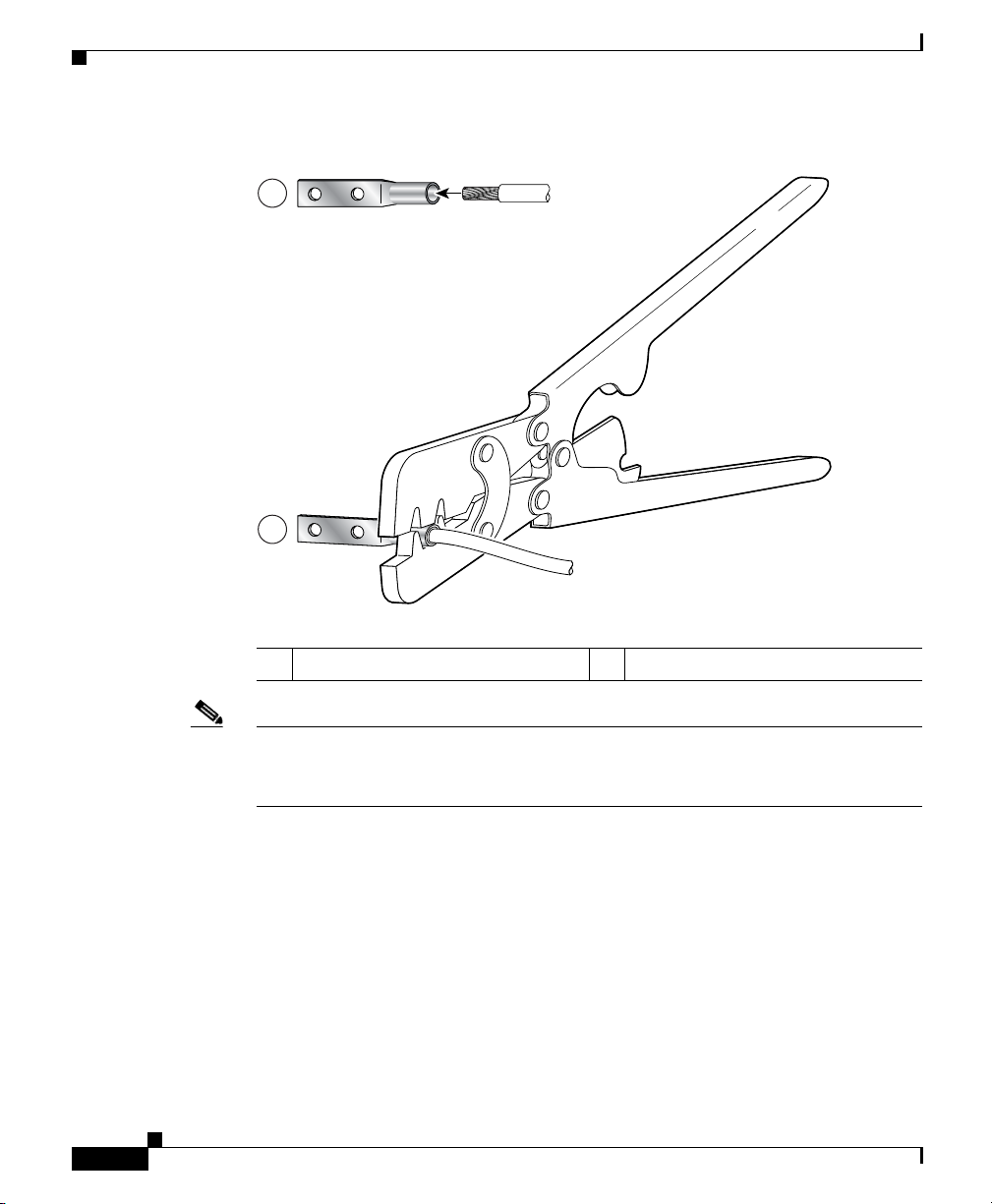
Supplemental Bonding and Grounding Connections
Figure 3-6 Crimping the Lug
1
2
Chapter 3 Installing the Cisco XR 12406 Router
57808
3-12
1
Place ground wire in the lug
Note The three threaded inserts that make up the grounding receptacle are set in a
2
Crimp the lug
triangle so that you can choose any two of the three holes to attach the lug and
grounding cable.
Cisco XR 12406 Router Installation Guide
OL-13831-01
Page 85
Chapter 3 Installing the Cisco XR 12406 Router
Connecting RP and Line Card Cables
Refer to Figure 3-7 and use the following procedure to connect RP and line card
cables.
Step 1 Proceeding from left to right, identify the cables that attach to the first RP or line
card.
Step 2 Connect the network interface cables:
a. Carefully route the identified cable through the cable-management tray and
over to the card interface port; connect one cable at a time.
b. Proceeding from left to right carefully wrap the cables using the velcro straps.
Caution Carefully adjust the cable in the cable-management brackets to prevent any kinks
or sharp bends in the interface cable. Kinks and sharp bends can destroy or
degrade the ability of the optical fiber to propagate the signal-encoded beam of
light accurately from one end of the cable to the other. Also, allow adequate strain
relief in the interface cable.
Connecting RP and Line Card Cables
OL-13831-01
Step 3 Route the cable through the fingers on the vertical chassis cable-management
bracket and turn the latch on the front of the bracket to secure the cables in the
bracket.
Cisco XR 12406 Router Installation Guide
3-13
Page 86

Connecting RP and Line Card Cables
Figure 3-7 Chassis Cable-Management Bracket
C
IS
C
O
1
2
0
0
GIGABIT SWITCH ROUTER
Chapter 3 Installing the Cisco XR 12406 Router
T
C
E
1
J
-
E
T
O
T
L
E
S
S
0
E
T
R
O
L
S
X
U
A
CONSOLE
0
S
E
R
I
E
S
L
L
O
X
C
R
5
4
J
R
K
X
N
I
T
L
I
I
M
GIGABIT ROUTE PROCESSOR
3-14
101833
Cisco XR 12406 Router Installation Guide
OL-13831-01
Page 87

Chapter 3 Installing the Cisco XR 12406 Router
Connecting Alarm Card Cables
The Cisco XR 12406 router has two alarm cards. Each alarm card is equipped with
a standard DB-9 connector, labeled ALARM. This connector can be used to
connect the router to an external site alarm maintenance system so that critical,
major, and minor alarms generated in the router also energize alarm relays on the
alarm card which activate the external site alarm. Appendix A, “Cisco XR 12406
Router Technical Specifications and Warnings,” lists the pin-to-signal
correspondence between the connector pins and the alarm card relay contacts.
Because alarm connector cables are entirely dependent on installation site
circumstances, these cables are not available from Cisco Systems.
Note Only safety extra-low voltage (SELV) circuits can be connected to the alarm
connector. Maximum rating for the alarm circuit is 2A, 50VA.
To comply with the intrabuilding lightning surge requirements of
GR-1089-CORE, Issue II, Revision 01, February 1999, use a shielded cable when
connecting to the external alarm port on the alarm card. The cable must consist of
shielded cable terminated by shielded connectors on both ends, with the cable
shield material tied to both connectors.
Connecting Alarm Card Cables
Connecting to the Console and Auxiliary Ports
This section provides the information for connecting console terminals and other
auxiliary devices to the console and auxiliary ports on the router. Both Data Set
Ready (DSR) and Data Carrier Detect (DCD) signals are active when the system
is running. The console port does not support modem control or hardware flow
control.
The system console port on the PRP is a DCE RJ-45 receptacle for connecting a
data terminal, which you must configure. The console port is labeled Console, as
shown in Figure 3-8.
Cisco XR 12406 Router Installation Guide
OL-13831-01
3-15
Page 88

Connecting to the Console and Auxiliary Ports
Check your terminal’s documentation to determine the baud rate of the terminal
you plan to use. If your documentation does not specify settings use the following
terminal settings:
1. Baud to 9600
2. Data bits to 8
3. Parity to no parity
4. Stop bits to 2
The console port requires a straight-through RJ-45 cable.
Note To comply with Telcordia GR-1089 NEBS standard for electromagnetic
compatibility and safety, connect all console, auxiliary, Ethernet, and BITS
interfaces only to intrabuilding or non-exposed wiring or cabling. The
intrabuilding cable must be shielded and the shield must be grounded at both ends.
Figure 3-8 PRP Console and Auxiliary Port Connections
Chapter 3 Installing the Cisco XR 12406 Router
3-16
1
2
1 Modem 4 Auxiliary port
2 Console terminal 5 Console port
3 RJ-45 Ethernet cables – —
Cisco XR 12406 Router Installation Guide
S
L
S
O
LO
T
PRIMARY
-0
T
-1
L
IN
E
K
N
T
X
R
X
PRIMARY
ETH 1ETH 0 AUX
L
IN
E
K
3
N
T
X
R
X
4
CONSOLE
5
70692
OL-13831-01
Page 89

Chapter 3 Installing the Cisco XR 12406 Router
Note The console and auxiliary ports are both asynchronous serial ports; any devices
connected to these ports must be capable of asynchronous transmission.
Asynchronous is the most common type of serial device; for example, most
modems are asynchronous devices.
PRP Console Port Signals
The console port on the PRP is a DCE RJ-45 receptacle. Table 3-1 lists the
signal-to-pin correspondence for the PRP console port.
Table 3-1 PRP Console Port Signals
Console Port Pin Signal Input/Output Description
1
1
2 DTR Output Data Terminal Ready
3 TxD Output Transmit Data
4 GND — Signal Ground
5 GND — Signal Ground
6 RxD Input Receive Data
7 DSR Input Data Set Ready
1
8
1. These pins are not connected.
Connecting to the Console and Auxiliary Ports
—— —
—— —
PRP Auxiliary Port Signals
The auxiliary port on the PRP is a DTE, RJ-45 plug for connecting a modem or
other DCE device (such as a CSU/DSU or another router) to the router. The port
is labeled AUX , as shown in Figure 3-8. The asynchronous auxiliary port supports
hardware flow control and modem control. Table 3-2 lists the signal-to-pin
correspondence for the PRP auxiliary port.
OL-13831-01
Cisco XR 12406 Router Installation Guide
3-17
Page 90

Installing a Flash Memory Card
Table 3-2 PRP Auxiliary Port Signals
Auxiliary Port Pin Signal Input/Output Description
1 RTS Output Request To Send
2 DTR Output Data Terminal Ready
3 TxD Output Transmit Data
4 GND — Signal Ground
5 GND — Signal Ground
6 RxD Input Receive Data
7 DSR Input Data Set Ready
8CTSInputClear To Send
Installing a Flash Memory Card
By default, a Flash memory card (Figure 3-9) containing a valid Cisco IOS XR
software image is inserted in PCMCIA slot 0 before the router is shipped.
PCMCIA slot 0 (SLOT-0) is the bottom slot and slot 1 (Slot-1) is the top slot. Both
Flash memory card slots on each RP can be used at the same time.
Chapter 3 Installing the Cisco XR 12406 Router
3-18
The software configuration register is set to 0x0102, which causes the router to
boot automatically from the Cisco IOS XR software image stored on the Flash
memory card.
Cisco XR 12406 Router Installation Guide
OL-13831-01
Page 91

Chapter 3 Installing the Cisco XR 12406 Router
Figure 3-9 Flash Memory Card Slot Opening
Ensure that a console terminal is connected to the RP console port and turned on,
or that you have a remote login to the router from another device through a Telnet
session.
Connecting the PRP to an Ethernet Network
T
C
-1
T
T
E
E
J
O
S
E
L
E
S
R
-0
T
O
L
S
AUX
57080
Connecting the PRP to an Ethernet Network
The PRP includes two 10/100 Mbps Ethernet ports, each using an 8-pin RJ-45
receptacle for either IEEE 802.3 10BASE-T (10 Mbps) or IEEE 802.3u
100BASE-TX (100 Mbps) connections. The transmission speed of the Ethernet
ports is auto-sensing by default and is user configurable.
To connect cables to the PRP Ethernet interfaces (ports labeled ETH0 and ETH1),
attach the Category 5 UTP cable directly to a RJ-45 receptacle on the PRP.
Note The Ethernet interfaces on the PRP are end-station devices, not repeaters;
therefore, you must connect an Ethernet interface to a repeater or hub.
RJ-45 cables are not available from Cisco Systems, but are available from outside
commercial cable vendors.
Cisco XR 12406 Router Installation Guide
OL-13831-01
3-19
Page 92

Connecting the PRP to an Ethernet Network
Note Use cables that comply with EIA/TIA-568 standards. See Table 3-4 on page 3-23
and Table 3-5 on page 3-24 for cable recommendations and specifications.
Note To comply with Telcordia GR-1089 NEBS standard for electromagnetic
compatibility and safety, connect all console, auxiliary, and Ethernet interfaces
only to intrabuilding or non-exposed wiring or cabling. The intrabuilding cable
must be shielded and the shield must be grounded at both ends.
Caution The Ethernet ports are used primarily as Telnet ports into the router, and for
booting or accessing Cisco IOS XR software images over a network to which an
Ethernet port is directly connected. Cisco Express Forwarding (CEF) functions
are switched off by default for security reasons. Cisco strongly cautions you to
consider the security implications of switching on CEF routing functions on these
ports.
Chapter 3 Installing the Cisco XR 12406 Router
3-20
Figure 3-10 shows an example of the functionality of an Ethernet port. In this
example, you cannot access Network 2.0.0.0 through the Ethernet port (ETH0) on
the PRP in Router A; you can only access the hosts and Router C, which are in
Network 1.0.0.0 (see dotted arrows in Figure 3-10).
To access Network 2.0.0.0 from Router A, use an interface port on one of the line
cards (in this example, a Packet-over-SONET [POS] line card in Router A) to go
through Router B, through Router C, and into Network 2.0.0.0. (see solid arrows
in Figure 3-10).
Cisco XR 12406 Router Installation Guide
OL-13831-01
Page 93

Chapter 3 Installing the Cisco XR 12406 Router
Figure 3-10 Using the Ethernet Port on the PRP
Connecting the PRP to an Ethernet Network
Router A
(Cisco 12000 series)
POS
Router B
(Cisco 7500 series)
PRP Ethernet Connections
Figure 3-11 shows a PRP RJ-45 receptacle and cable connector. The RJ-45
connection does not require an external transceiver. The RJ-45 connection
requires Category 5 unshielded twisted-pair (UTP) cables, which are not available
from Cisco Systems, but are available from commercial cable vendors. Table 3-3
lists the signal-to-pin correspondence for the RJ-45 receptacle.
Figure 3-11 RJ-45 Receptacle and Plug (Horizontal Orientation)
EO
EO
Network 1.0.0.0
Host A
Host B
Router C
(Cisco 7500 series)
Network 2.0.0.0
Host A
S6755
OL-13831-01
8 7 6 5 4 3 2 1
1 2
75043
1 RJ-45 receptacle 2 Category 5 UTP cable with plug
Cisco XR 12406 Router Installation Guide
3-21
Page 94

Connecting the PRP to an Ethernet Network
Chapter 3 Installing the Cisco XR 12406 Router
Warning
The ports labeled Ethernet, 10BASE-T, Token Ring, Console, and AUX are safety
extra-low voltage (SELV) circuits. SELV circuits should only be connected to
other SELV circuits. Because the BRI circuits are treated like telephone
network voltage, avoid connecting the SELV circuit to the telephone network
voltage (TNV) circuits.
Table 3-3 PRP RJ-45 Ethernet Receptacle Pinout
Ethernet Port Pin Signal Description
1 TxD+ Transmit data +
2 TxD– Transmit data –
3 RxD+ Receive data +
4 Termination Network No connection
5 Termination Network No connection
6 RxD– Receive data –
7 Termination Network No connection
8 Termination Network No connection
Depending on your RJ-45 cabling requirements, use the connector pinouts shown
in Figure 3-12 or Figure 3-13.
3-22
Figure 3-12 Straight-Through Cable Pinout (Connecting MDI Ethernet Port
to MDI-X Wiring)
MDI-X wiringMDI wiring
1 TxD+
2 TxD–
3 RxD+
6 RxD–
Cisco XR 12406 Router Installation Guide
1 RxD+
2 RxD–
3 TxD+
6 TxD–
H11007
OL-13831-01
Page 95

Chapter 3 Installing the Cisco XR 12406 Router
Figure 3-13 Crossover Cable Pinout for Connecting Two PRPs
Connecting the PRP to an Ethernet Network
PRP
1 TxD+
2 TxD–
3 RxD+
6 RxD–
PRP
1 TxD+
2 TxD–
3 RxD+
6 RxD–
75431
Table 3-4 lists the cabling specifications for 100-Mbps transmission over
unshielded twisted-pair (UTP) cables.
Note The transmission speed of the Ethernet ports is auto-sensing by default and is user
configurable.
Table 3-4 Specifications and Connection Limits for 100-Mbps
Tr a n s m i s s i o n
Parameter RJ-45
Cable specification Category 5
1
UTP, 22 to 24 AWG
2
Cable length (max) —
Segment length (max) 328 feet (100 m) for 100BASE-TX
Network length (max) 656 feet (200 m)
1. EIA/TIA-568- or EIA-TIA-568 TSB-36-compliant. Not supplied by Cisco.
2. AWG = American Wire Gauge. This gauge is specified by the EIA/TIA-568 standard.
3. This length is specifically between any two stations on a repeated segment.
3
(with 1 repeater)
OL-13831-01
Cisco XR 12406 Router Installation Guide
3-23
Page 96

Chapter 3 Installing the Cisco XR 12406 Router
Connecting to an AC Power Source
Table 3-5 lists IEEE 802.3u physical characteristics for 100BASE-TX.
Table 3-5 IEEE 802.3u Physical Characteristics
Parameter 100BASE-TX
Data rate (Mbps) 100
Signaling method Baseband
Maximum segment length 100 m between DTE
Media Category 5 UTP (for RJ-45)
Topology Star/Hub
1. DTE = data terminal equipment.
Connecting to an AC Power Source
This section presents the procedure for connecting your router to an AC power
source.
• Original series Cisco XR 12406 routers: A power factor corrector (PFC)
allows the power supply to accept AC power source voltage from an AC
power source operating from 100 to 120 VAC 20-amp service in North
America, and a range of from 185 to 264 VAC 16-amp service in an
international environment.
1
and repeaters
3-24
• Enhanced series Cisco XR 12406 routers: Supports 220 VAC only which
requires 20-amp service in North America, and 16-amp service in an
international environment.
Warning
The AC-input PEM power switch should be in the off position before connecting
to an AC power source.
When operating your router on a power source, the power supply bays must have
one of the following power combinations installed before operating the router
(Table 3-6):
Cisco XR 12406 Router Installation Guide
OL-13831-01
Page 97

Chapter 3 Installing the Cisco XR 12406 Router
Table 3-6 Required Power Combinations
Router Power Combination
AC power 1 AC-input power supply
DC power 1 DC-input PEM
Refer to Figure 3-14 and use the following procedure to connect AC power to the
AC PDU.
Note When operating your router on a single power module, the second power module
bay must have a blank filler (MAS-GSR-PWRBLANK=) installed to ensure EMI
compliance.
Connecting to an AC Power Source
1 power supply blank
2 AC-input power supplies
1 PEM blank
2 DC-input PEMs
OL-13831-01
Step 1 Attach an ESD-preventive strap to your wrist and connect the leash to the chassis
or to another grounded, bare metal surface.
Step 2 Locate the two AC power cords and remove them from their shipping packaging.
Verify that the AC power cords shipped with the power supplies are the correct
type for your site.
Note If you have received the wrong type of AC power cord, contact your
service representative for a replacement.
Cisco XR 12406 Router Installation Guide
3-25
Page 98

Connecting to an AC Power Source
Step 3 Plug the socket end of each AC power cord into a receptacle on the PDU
(Figure 3-14).
Figure 3-14 AC Power Distribution Unit
1
Chapter 3 Installing the Cisco XR 12406 Router
4
3
3-26
5
6
57650
2
1 Captive screws (four) 4 AC power distribution unit
2 AC power cord receptacle A 5 Guide pin
3 AC power cord receptacle B 6 Blower module connector
Cisco XR 12406 Router Installation Guide
OL-13831-01
Page 99

Chapter 3 Installing the Cisco XR 12406 Router
Step 4 Insert the plug end of each AC power cord into the AC power source outlet.
For full redundancy, connect each AC-input power supply to an independent
power circuit with its own circuit breaker. We also recommend that you use an
uninterruptable power source (UPS) to protect against power failures at your site.
Step 5 Verify that the AC power source circuit breaker servicing each of the AC-input
power supplies is switched on.
Connecting to a DC Power Source
Each DC PDU should be connected to separate DC sources using six threaded
terminals. Two terminals for negative (source DC), two terminals for positive
(source DC return), and two terminals for ground. The DC power cable leads
should be 6 American Wiring Gauge (AWG) high strand count wire. The PEM
accepts DC power source voltage from a dedicated 35–Amp service DC power
source operating between -48 to -60 VDC.
Connecting to a DC Power Source
OL-13831-01
Note We recommend each DC PDU be connected to an independent power source for
full redundancy. We also recommend that you use an uninterruptable power
source (UPS) to protect against power failures at your site.
Use the following procedure to connect the router to a DC power source.
Warning
Step 1 Attach an ESD-preventive strap to your wrist and connect the leash to the chassis
The circuit breaker switch on the faceplate of the DC-input PEM should be in
the OFF position.
or to another grounded, bare metal surface.
Cisco XR 12406 Router Installation Guide
3-27
Page 100

Connecting to a DC Power Source
Step 2 Locate the DC power blocks on the back of the PDU (Figure 3-15).
Figure 3-15 DC PDU
1
Chapter 3 Installing the Cisco XR 12406 Router
POW
ER B
+
GND
4
3
5
POWER A
6
+
GND
2
1 Captive screws (four) 4 DC PDU
2 DC power connector block (A) 5 Guide pin
3 DC power connector block (B) 6 Blower module connector
57992
3-28
Cisco XR 12406 Router Installation Guide
OL-13831-01
 Loading...