

Page 1

Cisco XR 12404 Router Installation Guide
March 2009
Americas Headquarters
Cisco Systems, Inc.
170 West Tasman Drive
San Jose, CA 95134-1706
USA
http://www.cisco.com
Tel: 408 526-4000
800 553-NETS (6387)
Fax: 408 527-0883
Text Part Number: OL-13830-02
Page 2

THE SPECIFICATIONS AND INFORMATION REGARDING THE PRODUCTS IN THIS MANUAL ARE SUBJECT TO CHANGE WITHOUT
NOTICE. ALL STATEMENTS, INFORMATION, AND RECOMMENDATIONS IN THIS MANUAL ARE BELIEVED TO BE ACCURATE BUT
ARE PRESENTED WITHOUT WARRANTY OF ANY KIND, EXPRESS OR IMPLIED. USERS MUST TAKE FULL RESPONSIBILITY FOR
THEIR APPLICATION OF ANY PRODUCTS.
THE SOFTWARE LICENSE AND LIMITED WARRANTY FOR THE ACCOMPANYING PRODUCT ARE SET FORTH IN THE INFORMATION
P
ACKET THAT SHIPPED WITH THE PRODUCT AND ARE INCORPORATED HEREIN BY THIS REFERENCE. IF YOU ARE UNABLE TO
LOCATE THE SOFTWARE LICENSE OR LIMITED WARRANTY, CONTACT YOUR CISCO REPRESENTATIVE FOR A COPY.
The following information is for FCC compliance of Class
A digital device, pursuant to part 15 of the FCC rules. These limits are designed to provide reasonable protection against harmful interference when
the equipment is operated in a commercial environment. This equipment generates, uses, and can radiate radio-frequency energy and, if not installed
and used in accordance with the instruction manual, may cause harmful interference to radio communications. Operation of this equipment in a
residential area is likely to cause harmful interference, in which case users will be required to correct the interference at their own expense.
The following information is for FCC compliance of
radio-frequency energy. If it is not installed in accordance with Cisco’s installation instructions, it may cause interference with radio and television
reception. This equipment has been tested and found to comply with the limits for a Class B digital device in accordance with the specifications in
part 15 of the FCC rules. These specifications are designed to provide reasonable protection against such interference in a residential installation.
However, there is no guarantee that interference will not occur in a particular installation.
Modifying the equipment without Cisco’s written authorization may res
A or Class B digital devices. In that event, your right to use the equipment may be limited by FCC regulations, and you may be required to correct
any interference to radio or television communications at your own expense.
You can determine whether your equipment is causing
equipment or one of its peripheral devices. If the equipment causes interference to radio or television reception, try to correct the interference by
using one or more of the following measures:
• Turn the television or radio antenna until the interference stops.
• Move the equipment to one side or the other of the television or radio.
• Move the equipment farther away from the television or radio.
• Plug the equipment into an outlet that is on a different circuit from the television or radio. (That is, make certain the equi
or radio are on circuits controlled by different circuit breakers or fuses.)
Modifications to this product not authorized by Cisco Systems, Inc.
The Cisco implementation of TCP header compress
part of UCB’s public domain version of the UNIX operating system. All rights reserved. Copyright © 1981, Regents of the University of California.
NOTWITHSTANDING ANY OTHER WARRANTY HEREIN, ALL DOCUMENT FILES AND SOFTWARE OF THESE SUPPLIERS ARE
PR
OVIDED “AS IS” WITH ALL FAULTS. CISCO AND THE ABOVE-NAMED SUPPLIERS DISCLAIM ALL WARRANTIES, EXPRESSED
OR IMPLIED, INCLUDING, WITHOUT LIMITATION, THOSE OF MERCHANTABILITY, FITNESS FOR A PARTICULAR PURPOSE AND
NO
NINFRINGEMENT OR ARISING FROM A COURSE OF DEALING, USAGE, OR TRADE PRACTICE.
IN NO EVENT SHALL CISCO OR ITS SUPPLIERS BE LIABLE FOR A
DAMAGES, INCLUDING, WITHOUT LIMITATION, LOST PROFITS OR LOSS OR DAMAGE TO DATA ARISING OUT OF THE USE OR
INABILITY TO USE THIS MANUAL, EVEN IF CISCO OR ITS SUPPLIERS HAVE BEEN ADVISED OF THE POSSIBILITY OF SUCH
DAMAGES.
CCDE, CCENT, Cisco Eos, Cisco HealthPresence, the Cisco logo, Cisco Lumin, Cisco Nexus, Cisco StadiumVision, Cisco TelePresence,
Cis
co WebEx, DCE, and Welcome to the Human Network are trademarks; Changing the Way We Work, Live, Play, and Learn and Cisco Store are
s
ervice marks; and Access Registrar, Aironet, AsyncOS, Bringing the Meeting To You, Catalyst, CCDA, CCDP, CCIE, CCIP, CCNA, CCNP, CCSP,
CCVP, Cisco, the Cisco Certified Internetwork Expert logo, Cisco IOS, Cisco Press, Cisco Systems, Cisco Systems Capital, the Cisco Systems logo,
Cis
co Unity, Collaboration Without Limitation, EtherFast, EtherSwitch, Event Center
HomeLink, Internet Quotient, IOS, iPhone, iQuick Study, IronPort, the IronPort logo, LightStream, Linksys, MediaT
MeetingPlace Chime Sound, MGX, Networkers, Networking Academy, Network Registrar, PCNow, PIX, PowerPanels, ProConnect, ScriptShare,
SenderBase, SMARTnet, Spectrum Expert, StackWise, The Fastest Way to Increase Your Internet Quotient, TransPath, WebEx, and the Web Ex logo
are r
egistered trademarks of Cisco Systems, Inc. and/or its affiliates in the United States and certain other countries.
A devices: This equipment has been tested and found to comply with the limits for a Class
Class B devices: The equipment described in this manual generates and may radiate
ult in the equipment no longer complying with FCC requirements for Class
interference by turning it off. If the interference stops, it was probably caused by the Cisco
pment and the television
could void the FCC approval and negate your authority to operate the product.
ion is an adaptation of a program developed by the University of California, Berkeley (UCB) as
NY INDIRECT, SPECIAL, CONSEQUENTIAL, OR INCIDENTAL
, Fast Step, Follow Me Browsing, FormShare, GigaDrive,
one, MeetingPlace,
Page 3

All other trademarks mentioned in this document or website are the property of their respective owners. The use of the word partner does not imply
a partnership relationship between Cisco and any other company. (0812R)
Any Internet Protocol (IP) addresses used in this document are not intended to be actual addresses. Any examples, command display ou
figures included in the document are shown for illustrative purposes only. Any use of actual IP addresses in illustrative content is unintentional and
coincidental.
Cisco XR 12404 Router Installation Guide
© 2009 Cisco Systems, Inc. All rights reserved.
tput, and
Page 4

Page 5

CONTENTS
Preface ix
Changes to This Document ix
Obtaining Documentation and Submitting a Service Request x
Audience x
Purpose xi
Installation Guide Organization xi
Document Conventions xii
CHAPTER
OL-13830-02
1 Cisco XR 12404 Router Overview 1-1
Router Overview 1-1
Physical and Functional Description of the Router 1-3
Route Processor 1-4
Performance Route Processor Overview 1-5
PRP Memory Components 1-12
Supported Line Cards 1-19
Consolidated Switch Fabric Card 1-21
Alarm Functionality 1-21
Switch Fabric Functionality 1-23
Clock and Scheduler Functionality 1-23
Power Entry Modules 1-23
AC PEMs 1-24
DC PEMs 1-25
Power Distribution 1-26
Cisco XR 12404 Router Installation Guide
5
Page 6

Contents
Fan Tray Assembly 1-26
Cable Management System 1-28
Maintenance Bus 1-31
Power-On/Off Control 1-31
CHAPTER
2 Preparing for Installation 2-1
Tools and Equipment 2-2
Safety and Compliance 2-2
General Safety Guidelines 2-3
Compliance and Safety Information 2-4
Preventing Electrostatic Discharge Damage 2-4
Laser Safety 2-6
Lifting Guidelines 2-6
Safety with Electricity 2-8
Installation Site Requirements 2-8
Rack-Mounting and Ventilation Guidelines 2-8
Environmental Guidelines 2-11
Power Connection Guidelines 2-13
Site Wiring 2-15
Unpacking and Repacking the Cisco XR 12404 Router 2-16
Transporting a Cisco XR 12000 Series Router 2-17
Site Preparation Checklist 2-17
CHAPTER
6
3 Installing the Router 3-1
Required Tools 3-2
Installing a Cisco XR 12404 Router 3-2
Installing the Rack-Mounting Brackets—Optional 3-3
Installing the Center-Mounting Brackets—Optional 3-5
Installing the Chassis in a Rack 3-7
Cisco XR 12404 Router Installation Guide
OL-13830-02
Page 7

Installing the Chassis on a Tabletop or Flat Surface 3-8
Supplemental Bonding and Grounding Connections 3-8
Connecting RP and Line Card Cables 3-12
Connecting to the Console Port and Auxiliary Ports 3-15
PRP Console Port Signals 3-17
PRP Auxiliary Port Signals 3-18
Installing a Flash Memory Card 3-18
Connecting the PRP to an Ethernet Network 3-20
Connecting to an AC Power Source 3-24
Connecting to a DC Power Source 3-26
Powering on the Router for the First Time 3-29
External Network Interface 3-33
Manually Booting the System 3-33
Contents
CHAPTER
CHAPTER
OL-13830-02
4 Troubleshooting the Installation 4-1
Identifying Startup Problems 4-2
Using the System LEDs to Troubleshoot 4-3
Problem-Solving with Subsystems 4-5
Troubleshooting an AC Power Subsystem 4-6
Troubleshooting the DC Power Subsystem 4-9
Troubleshooting the Processor Subsystem 4-13
Troubleshooting the RP 4-14
Troubleshooting the Line Cards 4-24
Troubleshooting the Cooling Subsystem 4-24
5 Maintaining the Router 5-1
Tools and Equipment 5-2
Powering Off the Router 5-3
Cisco XR 12404 Router Installation Guide
7
Page 8

Contents
Removing and Installing the Front Cover 5-4
Removing and Replacing the Air Filter 5-8
Removing and Replacing the Fan Tray Assembly 5-11
Troubleshooting the Fan Tray Assembly Installation 5-13
Removing and Replacing an AC Power Entry Module 5-14
Troubleshooting an AC PEM Installation 5-16
Removing and Replacing a DC Power Entry Module 5-17
Troubleshooting the DC PEM Installation 5-20
Removing and Replacing a DC PDU 5-21
Troubleshooting the DC PDU Installation 5-27
Removing and Replacing an RP or Line Card 5-29
Attaching the Cable-Management Bracket and Connecting Cables 5-32
Removing and Replacing a Consolidated Switch Fabric Card 5-36
Upgrading the RP and Line Card Memory 5-38
APPENDIX
I
NDEX
8
A Technical Specifications A-1
Product Architecture A-2
Specifications A-3
Compliance Information A-5
Regulatory, Compliance, and Safety Information A-8
Translated Safety Warnings and Agency Approvals A-8
Electromagnetic Compatibility Regulatory Statements A-8
Cisco XR 12404 Router Installation Guide
OL-13830-02
Page 9

Preface
Revised: March, 2009, OL-13830-02
The Cisco XR 12404 Router Installation Guide provides information related to
installation and removal of Cisco XR 12404 Router Chassis.
The preface contains the following sections:
• Changes to This Document
• Obtaining Documentation and Submitting a Service Request
• Audience
• Purpose
• Installation Guide Organization
• Document Conventions
Changes to This Document
Table 1 lists the technical changes made to this document since it was first printed.
OL-13830-02
Cisco XR 12404 Router Installation Guide
ix
Page 10

Preface
Obtaining Documentation and Submitting a Service Request
Ta b l e 1 Changes to This Document
Revision Date Change Summary
OL-13830-02 March 2009 Added Performance Route Processor
hardware details. Added Performance Route Processor-3
(PRP-3) hardware details. PRP-3 has been introduced in Cisco
IOS XR Software Release 3.8.0. PRP-3 will be supported on
Cisco IOS XR Software Release 3.8.0 and later releases.
-3 (PRP-3) related
Obtaining Documentation and Submitting a Service
Request
For information on obtaining documentation, submitting a service request, and
gathering additional information, see the monthly What’s New in Cisco Product
ocumentation, which also lists all new and revised Cisco technical
D
ocumentation, at:
d
http://www.cisco.com/en/US/docs/general/whatsnew/whatsnew.html
Subscribe to the Wh
Syndication (RSS) feed and set content to be delivered directly to your desktop using
a reader application. The RSS feeds are a free service and Cisco currently supports
RSS version 2.0.
at’s New in Cisco Product Documentation as a Really Simple
Audience
Cisco XR 12404 Router Installation Guide
x
The audience for the Cisco XR 12404 Router Installation Guide user
documentation are the people who will install and configure a
Cisco XR 12404 Router. The user typically has a substantial background in
nstalling and configuring router- and switch-based Internets but may or may not
i
have experience with Cisco products and supported protocols.
The reader of this documentation should be
wiring practices and have experience as an electronic or electromechanical
technician.
familiar with electronic circuitry and
OL-13830-02
Page 11

Preface
Purpose
This installation and configuration guide explains the hardware installation and
basic configuration procedures for a Cisco XR 12404 Router. It contains
rocedures for installing the hardware, creating a basic configuration file, and
p
starting up the router.
Installation Guide Organization
The Cisco XR 12404 Router Installation Guide has the following chapters and
appendix; the paper version of this document may contain an index.
• Chapter 1, “Cisco XR 12404 Router Overview”—Contains a high-level
system overview and physical description of the major components of a
Cisco XR 12404 Router including the power and cooling systems, the power
irements, the Route Processor (RP), PRP-3, and the consolidated switch
requ
fabric (CSF) card which contains the clock and scheduler, alarm and switch
fabric functions.
• Chapter 2, “Preparing for Installation”—Contains safety, site requirements
for power, environmental safety, cab
discharge (ESD), the site log, and site preparation checklist.
Purpose
ling, rack-mounting, electrostatic
OL-13830-02
• Chapter 3, “Installing the Router”—Contains procedures for verifying the
Cisco XR 12404 Router installation, grounding, cable connection, AC-and
C-power source and powering-up the router.
D
• Chapter 4, “Troubleshooting the Installation”—Contains procedures for
identifying and solving problems that may occur during installation.
• Chapter 5, “Maintaining the Router”—Contains safety at the field
replaceable unit (FRU) level, remov
field-replaceable units, FRU assemblies, and associated procedures to
troubleshoot and verify each FRU.
• Appendix A, “Technical Specifications”—Contains Cisco XR 12404 Router
specifications.
• Index—Contains a keyword and subject index of pertinent terms and
information.
al and replacement procedures for
Cisco XR 12404 Router Installation Guide
xi
Page 12

Document Conventions
Document Conventions
This publication uses the following conventions:
• The key combination Ctrl-z means hold down the Control key while you
press the z key.
Command descriptions use these conventions:
• Examples that contain system prompts denote interactive sessions, indicating
the commands that you should enter at the prompt. The system prompt
indicates the current level of the EXEC command interpreter.
Preface
For example, the prompt
level, and the prompt
router> indicates that you should be at the user
router# indicates that you should be at the privileged
level. Access to the privileged level usually requires a password. Refer to the
related software configuration and reference documentation for additional
information.
• Commands and keywords are in bold font.
• Arguments for which you supply values are in italic font.
• Elements in square brackets ([ ]) are optional.
• Alternative but required keywords are grouped in braces ({ }) and separated
by vertical bars (|).
Examples use these conventions:
• Terminal sessions and sample console screen displays are in screen font.
• Information you enter is in boldface screen font.
• Nonprinting characters, such as passwords, are in angle brackets (< >).
• Default responses to system prompts are in square brackets ([ ]).
• Exclamation points (!) at the beginning of a line indicate a comment line.
Caution Means reader be careful. You are capable of doing something that might result in
equipment damage or loss of data.
xii
Note Means reader take note. Notes contain helpful suggestions or references to
materials not contained in this manual.
Cisco XR 12404 Router Installation Guide
OL-13830-02
Page 13

Preface
Document Conventions
Timesaver Means the described action saves time. You can save time by performing the
action described in the paragraph.
Warning
This warning symbol means danger. You are in a situation that could cause
bodily injury. Before you work on any equipment, be aware of the hazards
involved with electrical circuitry and be familiar with standard practices for
preventing accidents. To see translations of the warnings that appear in this
publication, refer to the Regulatory Compliance and Safety Information
document that accompanied this device.
OL-13830-02
Cisco XR 12404 Router Installation Guide
xiii
Page 14

Document Conventions
Preface
xiv
Cisco XR 12404 Router Installation Guide
OL-13830-02
Page 15

Cisco XR 12404 Router Overview
This chapter provides an overview of the Cisco XR 12404 router. It contains
physical descriptions of the router hardware and major components, and
functional descriptions of hardware-related features.
Router Overview
The Cisco XR 12404 router scales the Internet Service Provider edge from speeds
of T3/E3 (44.7/34.4 Mbps) up to OC-192/STM-64 or 10GE (10 Gbps).
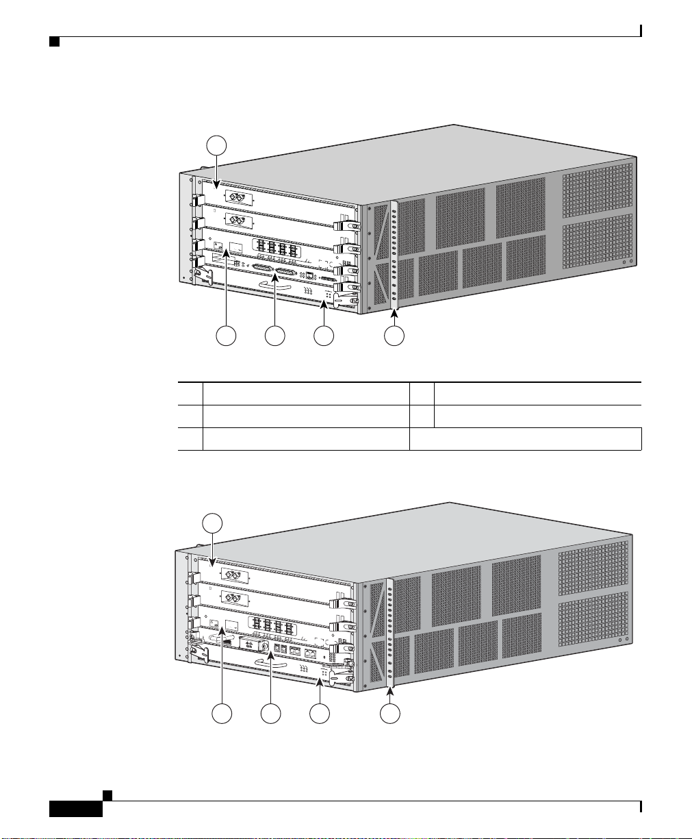
Figure 1-1 sho
locations of the Cisco XR 12404 router. Network interfaces reside on the line
cards tha
networks. The bottom slot (labeled Fabric Alarm) is a dedicated slot for the
combined CSF card.
CHA P TER
ws the PRP-2, consolidated switch fabric (CSF) card, and line card
t provide the connection between the router’s CSF and the external
1
OL-13830-02
Note Illustration is shown without the front door for clarity.
Cisco XR 12404 Router Installation Guide
1-1
Page 16
Router Overview
Chapter 1 Cisco XR 12404 Router Overview
Figure 1-1 Cisco XR 12404 Router—PRP2 Front View
1
CLASS 1 LASER PRODUCT
CLEAN
CO
N
NECTOR
LASERPRODUKT DER KLASSE 1
W
IT
H
A
L
C
O
H
O
L
W
I
P
E
S
B
E
F
O
PRODUIT LASER DE CLASSE 1
R
E
C
O
N
N
E
C
T
IN
G
PRODUCTO LASER DE CLASSE 1
0
EJECT
SLOT-1
RESET
SLOT-0
AUX
1
23
CONSOLE
TX
RX
COLL
TX
LINK
CRITICAL
MAJOR
ACTIVE
CARRIER
RX PKT
RX
MINOR
40C48/POS-SR-SC
RJ-45
MII
GIGABIT ROUTE PROCESSOR
MBUS
ALARM FABRIC
FAIL
ENABLE
CONSOLIDATED SWITCH FABRIC
5432
1 Line card 4 CSF card
2 Line card 5 Rack mounting bracket
3 Route Processor
66275
1-2
Figure 1-2 Cisco 12404 Router with PRP-3—Front View
1
CLASS 1 LASER PRODUCT
CLEAN
CO
NNECTOR
LASERPRO
W
IT
H
A
L
C
O
DUKT DER
H
O
L
W
IP
E
S
B
KLASSE 1
E
F
O
PRODUIT LASER DE CLASSE 1
R
E
C
O
N
N
E
C
T
IN
G
PRODUCTO LASER DE CLASSE 1
0
1
UP
Cisco XR 12404 Router Installation Guide
23
A
T
LINK
DA
A
T
LINK
DA
ETH 0
ETH
1
SIG
ACT
BITS 0
BITS 1
CRITICAL
TX
RX
ACTIVE
SIG
ACT
MAJOR
MINOR
CARRIER
RX PKT
AUX
CONSOLE
CONSOLIDATED SWITCH FABRIC
40C48/POS-SR-SC
RES
ET
PERFORMANCE RP3
MBUS
ALARM FABRIC
FAIL
ENABLE
272390
5432
OL-13830-02
Page 17

Chapter 1 Cisco XR 12404 Router Overview
Physical and Functional Description of the Router
Physical and Functional Description of the Router
The Cisco XR 12404 router supports up to 8 chassis in a one standard 7-foot
(2.15 meter) rack and has the following key features:
• Route processor (PRP-2)—The primary route processor is installed in it’s
own dedicated slot. A redundant route processor can go in any line card slot.
See the “Route Processor” section on page 1-4 for information.
• Line cards—The card cage contains 4 hot-swappable card slots. The router
can accommodate up to three OC-192 line cards (or 2 line cards if redundant
route processors are installed). See the “Supported Line Cards” section on
page 1-19 for information.
• Consolidated switch fabric card (CSF)—Switch fabric, alarm, and clock
schedule functions are located on one board. The CSF card has a switching
capacity of 10 Gbps. See the “Consolidated Switch Fabric Card” section on
page 1-21 for information.
• AC power entry module (PEM)—A customized and hot-swappable one-piece
unit. See the “Power Entry Modules” section on page 1-23 for information.
• DC power entry module (PEM) and DC power distribution unit (PDU)—Two
pieces that can be removed as one unit or in separate pieces. See the “Power
Entry Modules” section on page 1-23 for information.
OL-13830-02
Note When operating the router, both power module bays must have DC PEMs
and DC PDUs installed to ensure EMI compliance.
• Fan tray assembly—Supplies cooling air to the router. See the “Fan Tray
Assembly” section on page 1-26 for information.
• Cable management bracket used to neatly route line card cables. See the
“Cable Management System” section on page 1-28 for information.
• Maintenance Bus—Controls all of the MBus modules in the system. See the
“Maintenance Bus” section on page 1-31 for information.
Cisco XR 12404 Router Installation Guide
1-3
Page 18

Route Processor
Route Processor
The route processor for the Cisco XR 12404 router is the Performance Route
Processor (PRP-2). For detailed information about the PRP-2, refer to the Cisco
document, Performance Route Processor Installation and Configuration Guide.
The PRP-2 and PRP-3 performs the following primary functions:
• Executes routing protocol stacks
• Performs all protocol communications with other routers
• Builds and distributes forwarding information to all line cards
• Uploads the operating system software images to all installed line cards
during power-on
• Provides out-of-band system console and auxiliary ports and an Ethernet port
for router configuration and maintenance
• Monitors and manages the power and temperature of system components
such as line cards, power supplies, and fans
The Cisco PRP-2 and PRP-3 delivers all these functions with enhanced
erformance and capabilities. It also delivers the following feature enhancements
p
(depending on the software version running):
• 2 Ethernet management ports
Chapter 1 Cisco XR 12404 Router Overview
1-4
• Hard-drive support (optional part)
• BITS input ports
• 1 GB compact image Flash memory support (optional part)
• Memory scalability up to 4 GB with PRP-2 and up to 8 GB with PRP-3.
The PRP-2 and PRP-3 communicates with the li
fabric or through the MBus. The switch fabric connection is the main data path
for routing table distribution as well as for packets that are sent between the line
cards and the PRP. The MBus connection allows the PRP-2 and PRP-3 to
download a system bootstrap image, collect or load diagnostic information, and
perform general, internal system maintenance operations.
The PRP-2 can be designated as either th
or the Secure Domain router (SDR).
Cisco XR 12404 Router Installation Guide
ne cards either through the switch
e Designated System Controller (DSC)
OL-13830-02
Page 19
Chapter 1 Cisco XR 12404 Router Overview
The Designated System Controller (DSC) performs the following functions:
• Implements control plane operations for the chassis
• Monitors temperature and voltage
• Monitors line cards
• On boot up, the first card to become active is designated as the DSC.
The Secure Domain Router (SDR) controls
of any other SDRs on the network.
In addition to the functionality listed for the PRP-2, PRP-3 provides the following
ic functions:
specif
• Reduced boot time.
• Increased overall scalability.
• Improved memory access rates and scale.
• Improved CPU performance through dual 1.3-GHz PPC processor cores.
• Improved packet processing using hardware-based acceleration.
• 10-G bandwidth backplane connectivity.
• Support for all 124xx and 128xx chassis, except low–speed fabric (2.5 G).
• New ROMMON that supports IPv4 network configuration directly.
Route Processor
domain security features independent
Performance Route Processor Overview
The performance route processor (PRP-2) uses a Motorola PowerPC 7457 CPU
that runs at an external bus clock speed of 133 MHz and has an internal clock
speed of 1.3 GHz.
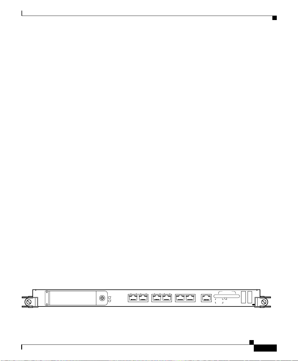
Figure 1-3 i
Figure 1-3 Performance Route Processor-2 (PRP-2) Front Panel
OL-13830-02
dentifies the slots, ports, and LEDs on the PRP front panel.
ACT
SIG
ACT
DATA
SLOT-1
SLOT-0
LINK
SIG
DATA
LINK
ETH 1ETH 0
BITS 1BITS 0
CONSOLE ETH 2AUX
Cisco XR 12404 Router Installation Guide
RESET
PERFORMANCE ROUTE PROCESSOR 2
101104
1-5
Page 20
Chapter 1 Cisco XR 12404 Router Overview
Route Processor
Ta b l e 1-1 Performance Route Processor-2 (PRP-2) Front Panel Hardware Components
1 PCMCIA flash disk slots (shown with cover in
ace) and slot LEDs
pl
4 Console serial port
2 RJ-45 Ethernet ports and data status LEDs 5 Reset button
3 Auxiliary serial port 6 Alphanumeric messages
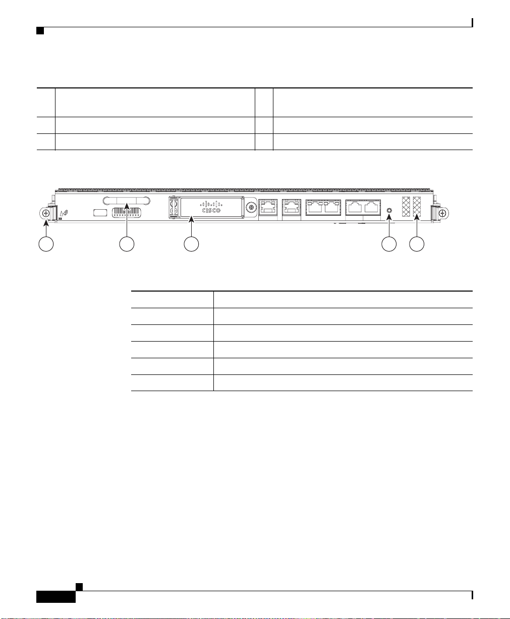
Figure 1-4 Performance Route Processor 3 (PRP-3) Front Panel
LINK
LINK
DATA
DATA
ACT
ACT
SIG
SIG
CONSOLE
AUXBITS 1BITS 0ETH 1ETH 0
1 3 4 52
Ta b l e 1-2 PRP-3 Front Panel Hardware Components Detail
Numeric Callout Hardware Components
1 Ejecter Lever
2 Handle
3 External Compact Flash
4 Reset button
5 Alphanumeric LEDs
RESET
PERFORMANCE RP 3
272359
1-6
PRP-3 is the route processor for the Cisco XR 12404 and 12804 Router chassis
running Cisco IOS XR Software Release 3.8.0 or a later release. The PRP-3 is
available as product number PRP-3 or PRP-3= for a primary route processor and
is available as PRP-3/R for a redundant route processor. PRP-3 has significant
improvements over PRP-2. These improvements include increased speed,
improved scalability, higher system memory, faster packet processing. Because
PRP-3 does not support Cisco IOS, the bootflash memory no longer exists in
PRP-3. PRP-3 ROMMON has software intelligence to download a Cisco IOS XR
image without the support of bootflash memory.
Cisco XR 12404 Router Installation Guide
OL-13830-02
Page 21

Chapter 1 Cisco XR 12404 Router Overview
Note PRP-3 supports Cisco XR 12404 (10 G per slot fabric) and Cisco XR 12804 (40
G per slot fabric) Router chassis only. PRP-3 does not support Cisco XR 12004,
12006, 12010, and 12016 Router chassis (2.5 G low-speed fabric).
PRP PCMCIA Card Slots and Status LEDs
Two PCMCIA card slots (slot 0 and slot 1) provide the PRP with additional flash
memory capacity. All combinations of different flash devices are supported by the
PRP. You can use ATA flash disks, Type 1 or Type 2 linear flash memory cards,
or a combination of the two.
Note The PRP only supports +5.2 VDC flash memory devices. It does not support
+3.3 VDC PCMCIA devices.
Status LEDs (Slot-0 / Slot-1) indicate when the flash memory card in that slot is
acc
essed (see Figure 1-3). Each slot has an eject button (located behind the cover)
to remove a flash card from the slot.
Route Processor
Note PRP-3 does not have PCMCIA slots (slot 0 and slot 1). PRP-3 has an external
CompactFlash (disk0:) that replaces the PCMCIA slots.
PRP Ethernet Ports and Status LEDs
The PRP has two 8-pin media-dependent interface (MDI) RJ-45 ports for either
IEEE 802.3 10BASE-T (10 Mbps) or IEEE 802.3u 100BASE-TX (100 Mbps)
rnet connections. These ports are labeled ETH 0 and ETH 1.
Ethe
The transmission speed of the Ethernet port is not user-configurable. You set the
eed through an autosensing scheme on the PRP which is determined by the
sp
network that the Ethernet port is connected to. However, even at an autosensed
data transmission rate of 100 Mbps, the Ethernet port can only provide a usable
bandwidth of substantially less than 100 Mbps. You can expect a maximum usable
bandwidth of approximately 20 Mbps when using an Ethernet connection.
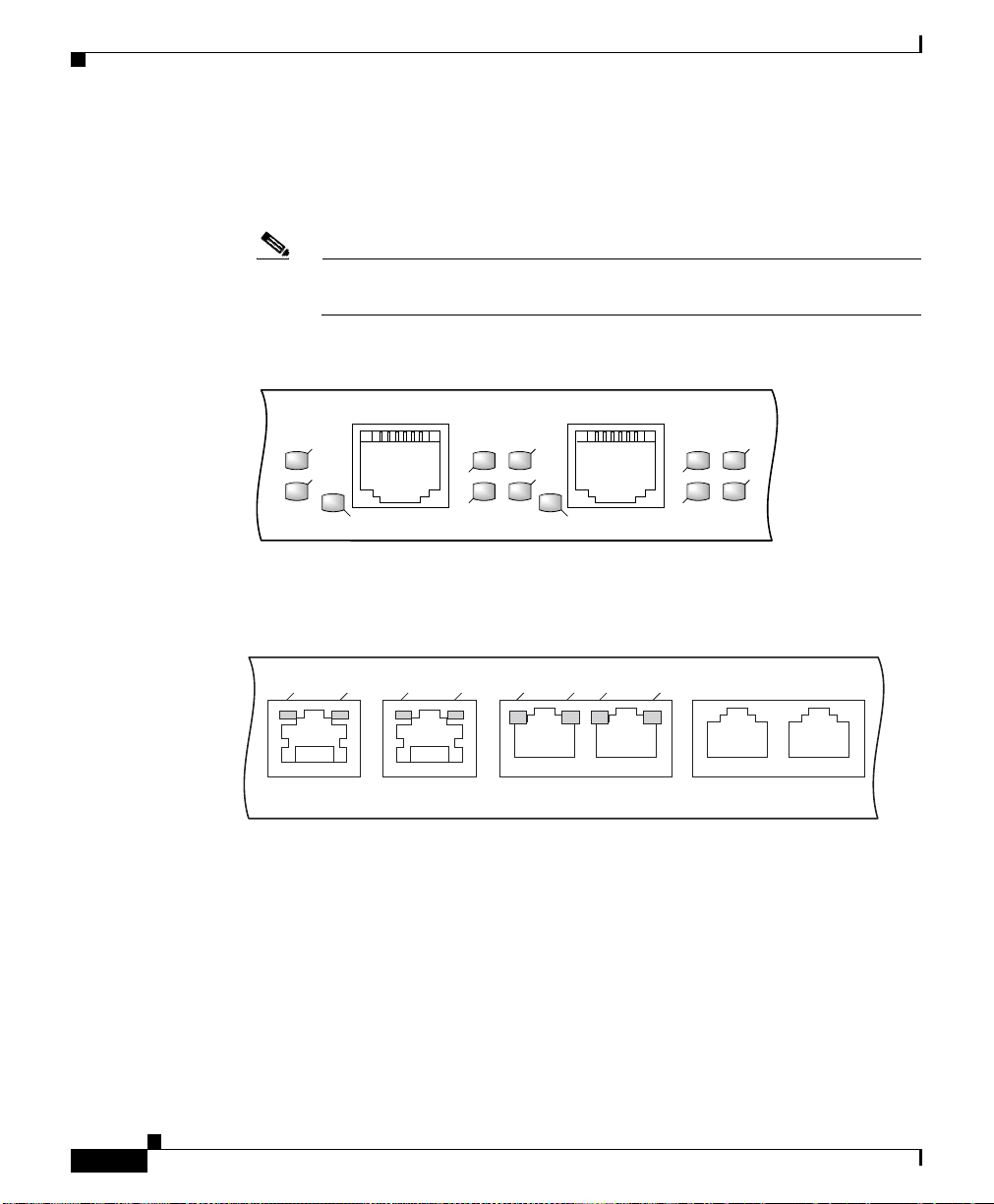
The following LEDs on the front panel indicate traf
(Figure 1-5):
OL-13830-02
fic status and port selection
Cisco XR 12404 Router Installation Guide
1-7
Page 22
Route Processor
Chapter 1 Cisco XR 12404 Router Overview
• LINK, EN, TX, RX—Indicate link activity (LINK), port enabled (EN), data
transmission (TX), and data reception (RX).
• PRIMARY—Indicates which Ethernet port is selected (ETH 0 or ETH 1).
Note Because both ports are supported on the PRP, ETH 0 is always on. ETH 1
lights when it is selected.
Figure 1-5 PRP-2 Port Activity LEDs—Partial Front Panel
ETH 1ETH 0
SLOT-1
SLOT-0
PRIMARY
Figure 1-6 PRP-3 Port Activity LEDs—Partial Front Panel
DATA
LINK
ETH 1ETH 0
PRP Auxiliary and Console Ports
The auxiliary and console ports on the PRP are EIA/TIA-232 (also known as
RS-232) asynchronous serial ports. These ports connect external devices to
monitor and manage the system.
LINK
EN
LINK
DATA
RX
TX
SIG
BITS 0
RX
TX
70693
PRIMARY
SIG
ACT
EN
LINK
ACT
BITS 1 AUX CONSOLE
272388
1-8
Cisco XR 12404 Router Installation Guide
OL-13830-02
Page 23

Chapter 1 Cisco XR 12404 Router Overview
• The auxiliary port—A (male) plug that provides a data terminal equipment
(DTE) interface. The auxiliary port supports flow control and is often used to
connect a modem, a channel service unit (CSU), or other optional equipment
for Telnet management.
• The console port—A (female) receptacle that provides a data
circuit-terminating equipment (DCE) interface for connecting a console
terminal.
PRP-3 LEDs
The PRP-3 has the following LED indicators:
• Two Ethernet port LEDs used in conjunction with each of the three RJ-45
Ethernet connectors:
–
–
• Two BITS port LEDs used in conjunction with each of the two BITS ports:
–
–
Route Processor
LINK—Indicates link activity
DATA—Indicates data transmission or reception
SIG—Indicates carrier signal available
ACT—Indicates that the interface is active
Note BITS feature is not supported in Release 3.8.0.
PRP Reset Switch
OL-13830-02
• One auxiliary port (AUX) and one console port (CONSOLE) LED:
–
AUX—Used as a backup for the command outputs on the Console.
–
CONSOLE—Used for configuring the router by connecting an RJ-45
cable to the console terminal. The router can be configured through the
console terminal.
Access to the (soft) reset switch is through a small opening in the PRP front panel
(see Figure 1-3). To press the switch, insert a paper
clip or similar small pointed
object into the opening.
Cisco XR 12404 Router Installation Guide
1-9
Page 24
Route Processor
Caution The reset switch is not a mechanism for resetting the PRP and reloading the
Cisco IOS image. It is intended for software development use only. To prevent
em problems or loss of data, use the reset switch only on the advice of Cisco
syst
service personnel.
Pressing the reset switch causes a nonmaskable interrupt (NMI) and places the
PRP in
ROM monitor mode. When the PRP enters ROM monitor mode, its
behavior depends on the setting of the PRP software configuration register. For
example, if the boot field of the software configuration register is set to:
• 0x0—The PRP remains at the ROM monitor prompt (rommon>) and waits for
a user command to boot the system manually.
• 0x1—The system automatically boots the first Cisco IOS image found in
flash memory on the PRP.
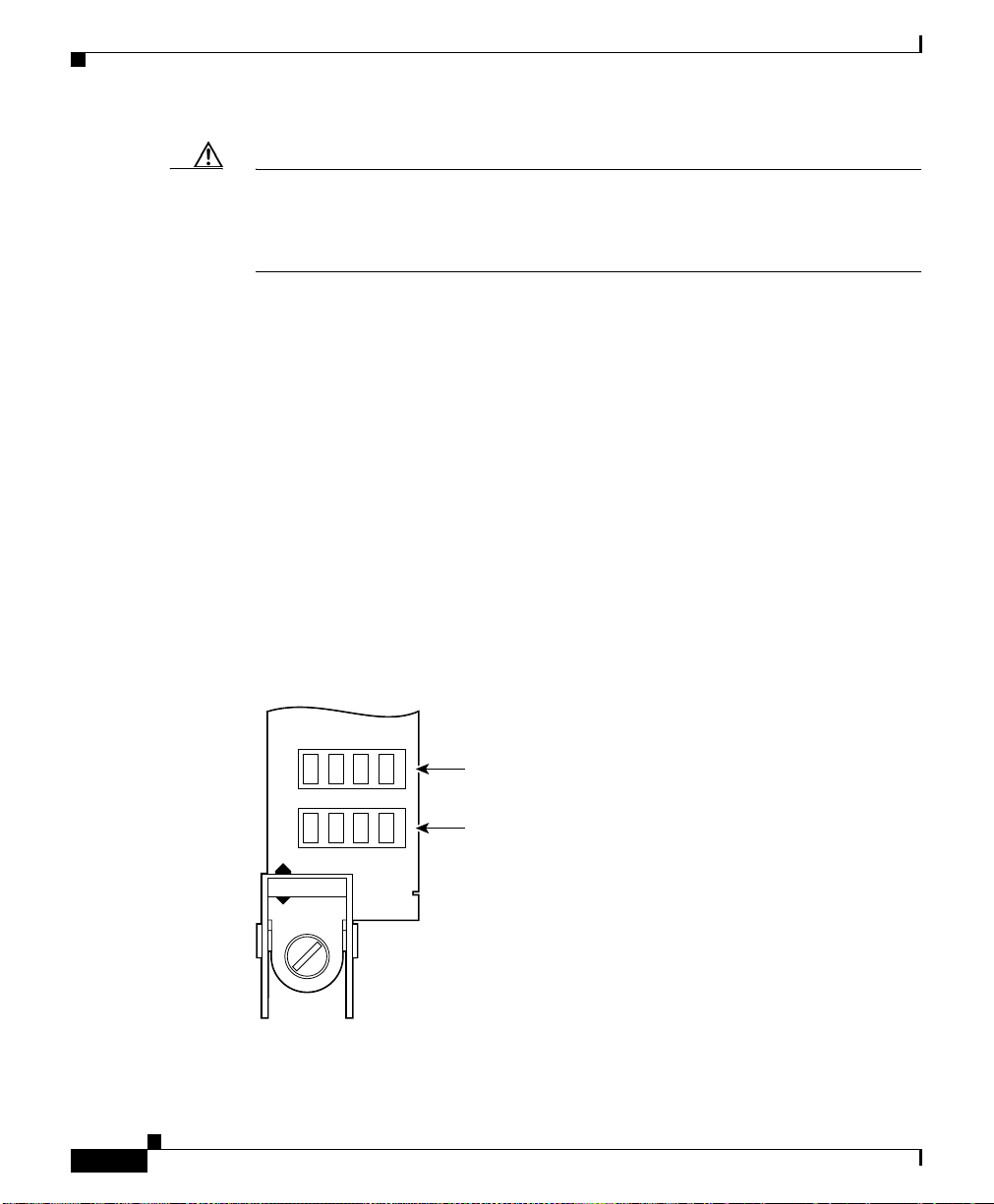
PRP Alphanumeric Message Displays
The alphanumeric message displays are organized in two rows of four LED
characters each (Figure 1-7).
Chapter 1 Cisco XR 12404 Router Overview
1-10
Figure 1-7 Alphanumeric Message Displays—Partial Front Panel
PROCESSOR
Upper alphanumeric
LED display (four digits)
Lower alphanumeric
LED display (four digits)
H10780
The alphanumeric message displays show router status messages during the boot
process, and after the boot process is complete.
Cisco XR 12404 Router Installation Guide
OL-13830-02
Page 25

Chapter 1 Cisco XR 12404 Router Overview
• During the boot process, the message displays are controlled directly by the
MBus module.
• After the boot process, the message displays are controlled by Cisco IOS XR
software (through the MBus).
The alphanumeric message displays also pro
levels of system operation, including the status of the PRP, router error messages,
and user-defined status and error messages
Note A list of all system and error messages appears in the Cisco IOS System Error
Messages publication.
Route Processor
vide information about different
OL-13830-02
Cisco XR 12404 Router Installation Guide
1-11
Page 26

Chapter 1 Cisco XR 12404 Router Overview
Route Processor
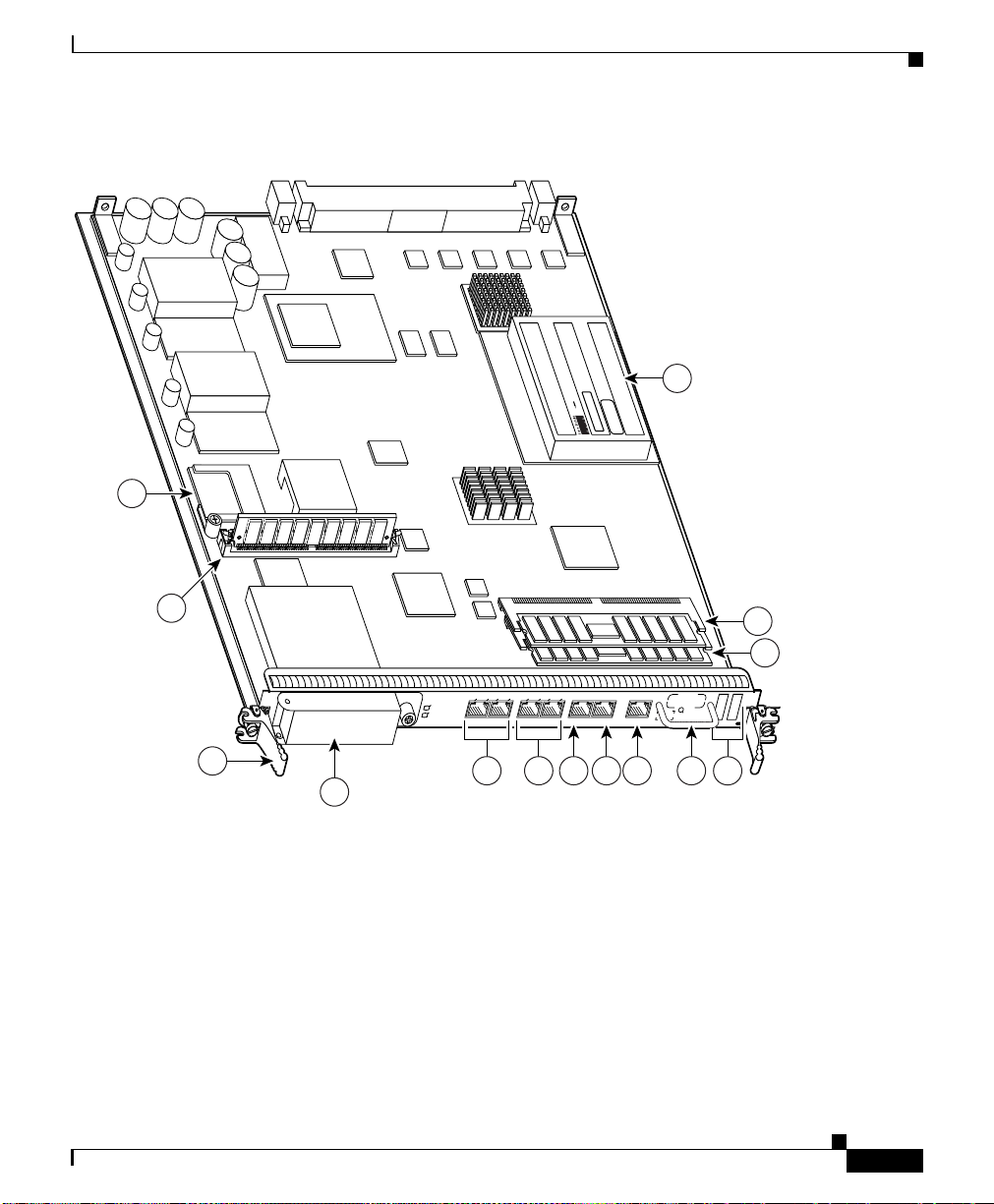
PRP Memory Components
This section describes various types of memory used on the PRP to support router
functions. Tab l e 1-3 provides a quick reference of the different types of memory,
and Figure 1-8 shows the location on the PRP board.
Ta b l e 1-3 PRP-2 Memory Components
Ty pe Size Quantity Description Location
1
SDRAM
2 GB (default)
or 4 GB
(optional)
3
SRAM
NVRAM
2 MB (fixed) — Secondary CPU cache memory functions —
4
2 MB (fixed) 1 System configuration files, register settings,
HDD 40 GB 1 Contains log and crash information for
Flash
memory
2 GB or 4 GB
(optional)
Compact
Flash
4 MB Boot
RO
M
Flash disks
GB (default)
GB
or 4
(optional)
1 GB CF
1. Default SDRAM configuration is 2-GB for PRP-2. Bank 1 (U15) must be populated first. You can use one or both banks to
configure SDRAM combinations of 2 GB and 4 GB for the PRP-2. 1.5-GB configurations.and DIMM devices that are not
from Cisco are not supported.
2. If both banks of the PRP-2 are populated, bank 1 and bank 2 must contain the same size DIMM.
3. SRAM is not user configurable or field replaceable.
4. NVRAM is not user configurable or field replaceable.
5. ATA Flash disks are supported in the PRP-2.
6. Optional PRP-2 hardware. Compact disks that are not from Cisco are not supported.
6
1 or 2 2-GB or 4-GB DIMMs (based on desired
SDRAM configuration) for main Cisco IOS
XR software functions
and logs
specific Cisco IOS XR versions.
1 Contains Cisco IOS XR boot image
(bootflash), crash information, and other
user-defined files
1 Stores the ROMMON minimum boot image
(MBI).
5
2
1 or 2 Contains Cisco IOS XR software images,
system configuration files, and other
user-defined files on up to two flash disks
1 Contains large Cisco IOS XR software
images
U15 (bank 1)
U18 (bank 2)
—
—
P3
—
Flash disk
slot 0 and
slot 1
—
2
1-12
Cisco XR 12404 Router Installation Guide
OL-13830-02
Page 27
Chapter 1 Cisco XR 12404 Router Overview
Figure 1-8 PRP-2 Memory Locations
1
HD-PR P2-40G
THIS SIDE TO FACEPLATE
Route Processor
800 -240 60-01 RE V__
14
OL-13830-02
2
13
12
EJECT
SLOT-1
SLOT-0
3
LINK
CONSOLE ETH 2AUX
BITS 1BITS 0
ETH 1ETH 0
7 8 9 105 6
ETH 2
PERFORMANCE ROUTE PROCESSOR 2
RESET
11
101105
ACT
SIG
ACT
SIG
DATA
LINK
DATA
4
Cisco XR 12404 Router Installation Guide
1-13
Page 28
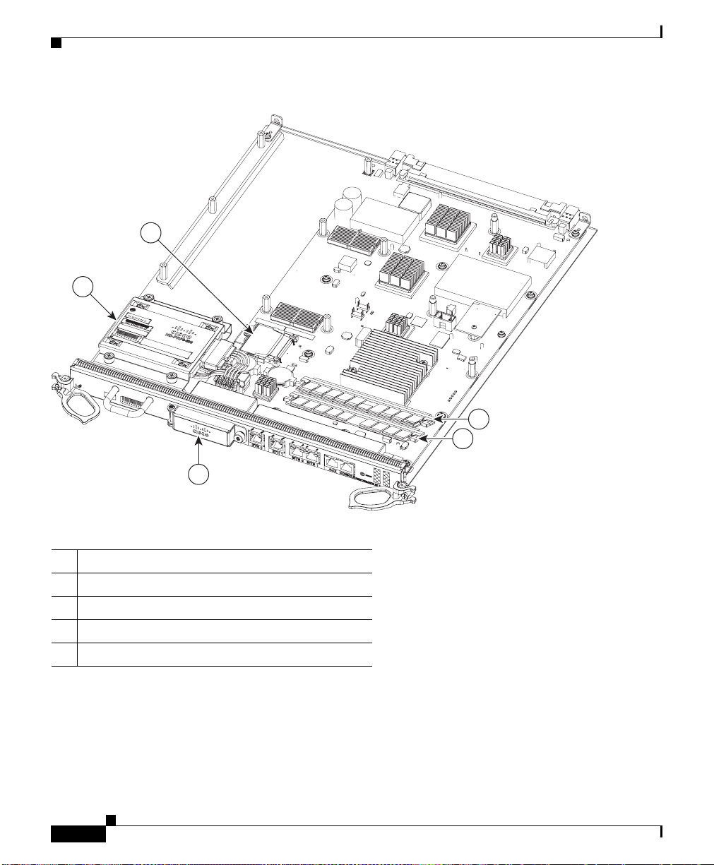
Route Processor
Figure 1-9 PRP-3 Memory Locations
5
Chapter 1 Cisco XR 12404 Router Overview
4
3
1 SDRAM DIMM: Bank 1 - Socket number U8
2 SDRAM DIMM: Bank 2 - Socket number U10
3 External CompactFlash
4 Hard disk (80 GB)
5 Internal CompactFlash
272360
1
2
1-14
Cisco XR 12404 Router Installation Guide
OL-13830-02
Page 29

Chapter 1 Cisco XR 12404 Router Overview
Route Processor
Ta b l e 1-4 PRP-3 Memory Components
Ty pe Size Quantity Description Location
SDRAM
NVRAM
1
3
2 GB (Default) for each
DDR2 DRAM for a total
system memory of 4 GB,
option for upgrade to total
system memory of 8 GB (4
GB each).
2 Two 2-GB default DDR2
AM for main CiscoIOSXR
DR
software functions. Provision
for optional upgrade to 4 GB
also possible to provide total
system memory of 8 GB.
2 MB (fixed) 1 System configuration files,
U8 (bank
2
1)
U10 (bank
2)
—
register settings, and logs
Flash memory 2 GB (default) or 4 GB
(optional) Flash disks
4
2
(Internal
and
External
Compact
Contains Cisco IOS XR
are images, system
softw
configuration files, and other
user-defined files on two
CompactFlash.
Internal and
nal
Exter
Compact
5
Flash
Flash)
Flash boot
ROM
6
HDD
8 MB 1 Flash EPROM for the ROM
monitor program boot image
80 GB SATA 1 Contains log and crash
—
—
information for specific
Cisco IOS XR versions
1. Default SDRAM configuration is a total of 4 GB (2 x 2GB) system memory for PRP-3. Bank 1 (U15) must be populated first.
You can use one or both banks to configure DDR2 DRAM combinations of 2 GB or 4 GB for the PRP-3. DIMM devices that
are not from Cisco are not supported.
2. If both banks of the PRP-3 are populated, bank 1 and bank 2 must contain the same size DIMM.
3. NVRAM is not user configurable or field replaceable.
4. ATA Flash disks are supported in the PRP-3.
5. PRP-3 provides an onboard internal CompactFlash and also an external CompactFlash. The external CompactFlash in PRP-3
replaces the two PCMCIA slots (slot0 and slot1) of PRP-2.
6. Hard disk drives that are not from Cisco are not supported.
OL-13830-02
Cisco XR 12404 Router Installation Guide
1-15
Page 30
Route Processor
PRP SDRAM
Chapter 1 Cisco XR 12404 Router Overview
The PRP uses Error Checking and Correction (ECC) Synchronized Dynamic
Random Access Memory (SDRAM) to store routing tables, protocols, network
accounting applications, and to run Cisco IOS software.
Table 1-5
• One DIMM—Bank 1 (U15) must be populated first.
• Two DIMMs—You cannot mix memory sizes; both banks must contain the
lists the DRAM configurations for the PRP. If you are using:
same size DIMM.
Ta b l e 1-5 PRP-2 DRAM Configurations
Total
SDRAM SDRAM Sockets Number of DIMMs
Total
RAM SDRAM Sockets Number of DIMMs
SD
2 GB
1
U15 (bank 1)
U18 (bank 2)
One 2 GB DIMM
or
Two 2 GB DIMMs
4 GB U15 (bank 1)
U18 (bank 2)
One 4 GB DIMM
or
Two 4 GB DIMMs
1. Default shipping configuration.
1-16
Caution DRAM DIMMs must be 3.3-volt, 60-nanosecond devices only. Do not attempt to
install other devices in the DIMM sockets. To prevent memory problems, use the
memory products approved by Cisco, listed in Table 1-5.
PRP-3 provides more system memory than PRP
-2. PRP-3 is shipped with 2 GB
of system memory in each DDR2 DRAMs, for a total of 4 GB and provides an
upgrade option for a total of 8 GB (4 GB x 2 DRAM).
Note The two DIMMs must be of the same sizes. Do not use two different DIMM sizes
together.
Cisco XR 12404 Router Installation Guide
OL-13830-02
Page 31

Chapter 1 Cisco XR 12404 Router Overview
Ta b l e 1-6 PRP3 DDR2 DRAM Configuration
Total SDRAM SDRAM Sockets Number of DIMMs
4 GB U8 (bank 1)
8 GB U8 (bank 1)
PRP SRAM
Static Random Access Memory (SRAM) provides 2 MB of secondary CPU cache
memory. Its principal function is to act as a staging area for routing table updates,
and for information sent to and received from the line cards. SRAM is not
user-configurable and cannot be upgraded in the field.
PRP NVRAM
Non-volatile Random Access Memory (NVRAM) provides 2 MB of memory for
system configuration files, software register settings, and environmental
monitoring logs. Built-in lithium batteries retain the contents of NVRAM for a
minimum of 5 years. NVRAM is not user configurable and cannot be upgraded in
the field.
Route Processor
Two 2 GB DIMMs
U10 (bank 2)
Two 4 GB DIMMs
U10 (bank 2)
PRP Flash Memory
OL-13830-02
Use flash memory to store multiple Cisco IOS XR software and microcode
images that you can use to operate the router. You can download new images to
flash memory over the network (or from a local server) to replace an existing
image, or to add it as an additional image. The router can be booted (manually or
automatically) from any of the stored images in flash memory.
Flash memory also functions as a Trivial File Transfer Protocol (TFTP) server to
ow other servers to boot remotely from the stored images, or to copy them into
all
their own flash memory.
The system uses two types of flash memory on PRP-2:
• Onboard flash memory (called bootflash)—Contains the Cisco IOS boot
image
• Flash memory disks (or cards)—Contain the Cisco IOS software image
Cisco XR 12404 Router Installation Guide
1-17
Page 32

Route Processor
Chapter 1 Cisco XR 12404 Router Overview
Table 1-7 lists supported flash disk sizes and Cisco part numbers.
Ta b l e 1-7 Supported Flash Disk Sizes
PRP-3 Compact Flash
Flash Disk Size
2
2 GB
1
Part Number
MEM-FD2G=
4 GB MEM-FD4G=
1. 4 GB is supported with 2 GB mode prior to Release 3.8.0.
2. Default shipping configuration.
PRP-3 provides more flash memory than PRP-2. PRP-3 uses flash memory to
store Cisco IOS XR software images. PRP-3 includes a default internal flash
memory of 2 GB and also has an external flash memory of 2 GB. A flash memory
upgrade option is also available for a total of 8 GB (2 x 4 GB).
PRP-2 and PRP-3 compactflashes are not compatible w
ith each other and hence
PRP-2 compactflash cannot be used in PRP-3 and vice versa. PRP-3 uses
Multiword DMA to access the compactflash device, a PRP-2 compactflash does
not support this access type.
Note The PRP-3 external CompactFlash disk replaces the two PCMCIA slots
of PRP-2. The external CompactFlash disk can be installed or removed
from the PRP-3 front panel. The internal CompactFlash disk memory is
denoted as compactflash, while the external CompactFlash disk is
denoted as disk0:.
1-18
Ta b l e 1-8 PRP-3 CompactFlash Disk Sizes
Flash Disk Size Part Numbers
2 GB FLASH-PRP3-2G(=)
4 GB FLASH-PRP3-4G(=)
Cisco XR 12404 Router Installation Guide
OL-13830-02
Page 33

Chapter 1 Cisco XR 12404 Router Overview
Supported Line Cards
The Cisco XR 12404 router is shipped with up to three installed line cards and
one route processor that provide a variety of network media types. Line card slots
and route processors shipped from the factory are based on your order.
Figure 1-10 shows the card cage slot locations:
• Line cards can be installed in slots 1 through 3 in the card cage.
• Slot zero (0) is the default slot for the primary route processor.
• The bottom slot is reserved for the consolidated switch fabric (CSF) card.
Note Refer to the software release notes for a current list of supported line cards (see
the “Obtaining Documentation and Submitting a Servic
page -x).
Figure 1-10 Card Slo t Locations
Supported Line Cards
e Request” section on
OL-13830-02
3
2
1
0
Fabric Alarm
The line cards interface to each other, and to the route processor through the CSF
card. Line cards installed in the Cisco XR 12404 router are hot swappable and can
replaced while the router is operating.
be
Cisco XR 12404 Router Installation Guide
1-19
66252
Page 34

Supported Line Cards
Chapter 1 Cisco XR 12404 Router Overview
Figure 1-11 shows examples of single-mode and multimode line cards.
Figure 1-11 Sample Line Cards
Single Mode
0
ACTIVE
CARRIER
RX PKT
1
ACTIVE
CARRIER
RX PKT
2
ACTIVE
CARRIER
RX PKT
3
ACTIVE
CARRIER
RX PKT
Q OC-3/STM-1 SM IR POS
Ejector lever
Port 0
Status LEDs
Port 1
Port 2
Port 3
Multimode
0
ACTIVE
CARRIER
RX PKT
1
ACTIVE
CARRIER
RX PKT
2
ACTIVE
CARRIER
RX PKT
3
ACTIVE
CARRIER
RX PKT
Q OC-3/STM-1 MM POS
160-pin
backplane
signal
connector
1-20
Alphanumeric
LED display
Ejector lever
Front view Rear view
Cisco XR 12404 Router Installation Guide
H10781
OL-13830-02
Page 35

Chapter 1 Cisco XR 12404 Router Overview
Consolidated Switch Fabric Card
The Cisco XR 12404 router CSF card contains the following functionality:
• Alarm notification and power source monitoring
• Switch fabric synchronized speed interconnections
• Clock and scheduler synchronization signaling
Alarm Functionality
The CSF card alarm functionality provides visual alarm notification of a fault
condition. The alarm card function indicates the following condition.
• Alarm status
• CSF MBus
• Alarm MBus status
• Fan fault monitoring
• AC or DC power source status
• DC PEM status
Consolidated Switch Fabric Card
OL-13830-02
–
The 5V MBus power supply has been integrated onto the CSF permitting
the use of generic PEMs in the chassis. The Cisco XR 12404 router can
or for the PEM for these conditions:
monit
• The operational status
• Output voltage
• Output current.
• Alarm Output Function
–
The alarm output function is controlled by the software on the route
processor. When a signal is received from the route processor the alarm
MBus module on the CSF card activates specific LEDs to signal a
condition that is critical, major, or minor.
Cisco XR 12404 Router Installation Guide
1-21
Page 36

Consolidated Switch Fabric Card
• LEDs
–
• CSF MBus Status
–
• The 5V MBus power supply
–
• Alarm Status
–
–
Chapter 1 Cisco XR 12404 Router Overview
LEDs alert you to a condition in the router. The determination of a
critical, major, or minor alarm condition is designed into Cisco IOS XR
tware running on your route processor.
sof
Drivers are provided for MBus OK and Fail indication.
Consists of a 100 W DC-DC converter.
The Alarm output function consists of a group of LEDs and their
associated drivers connected to an output port on the alarm MBus
module. As directed by the software on the route processor, the alarm
MBus module on the CSF card activates specific LEDs. The software
which drives these LEDs divides them into three levels, Critical, Major,
and Minor. The classification of a critical, major, or minor alarm is
determined by Cisco IOS XR software running on the route processor.
of the three LEDs is a dual LED (for failure redundancy).
Each
The OK/Fail pair of LEDs indicate the status of the alarm MBus:
Green indicates that the alarm MBus module is operating properly.
Amber Fail indicates that the alarm MBus
or with the MBus module.
Power Source Monitoring
The alarm MBus monitors the power supply and signals when there is a condition
outside the normal range of operation.
• Power source voltage is not being provided to a component
• A fault exist in the power source or PEM
• A voltage monitor signal is outside the allowable range
• The current monitor signal is outside the allowable range
Cisco XR 12404 Router Installation Guide
1-22
has detected an error in itself
OL-13830-02
Page 37

Chapter 1 Cisco XR 12404 Router Overview
Switch Fabric Functionality
Switch fabric circuitry provides up to 40 Gbps (full duplex) of synchronized speed
interconnections that carries user traffic between line cards or between the route
processor and the line cards.
Clock and Scheduler Functionality
The fabric card generates and distributes system-wide clock and cell time
synchronization signaling. System clock generation is delivered to the system
through the backplane and local clock functions are derived from the system
clock.
• System Clock—The system clock synchronizes data transfers between line
cards or between the route processor and a line card through the CSF. The
system clock signal is sent to all line cards and the route processor.
• Scheduler—The scheduler handles requests from the line cards for access to
the CSF. When the scheduler receives a request from a line card for CSF
access, the scheduler determines when to allow the line card access to the
CSF.
Power Entry Modules
Power Entry Modules
The Cisco XR 12404 router chassis supports two hot swappable AC or DC PEMs.
The router must be populated with 2 PEMs to meet EMI standards.
Caution Do not mix PEM types in the router. PEMs must be the same type; either both
AC PEMs, or both DC PEMs and PDUs.
OL-13830-02
Cisco XR 12404 Router Installation Guide
1-23
Page 38

Power Entry Modules
AC PEMs
Chapter 1 Cisco XR 12404 Router Overview
Each AC PEM converts 200 to 240 VAC into -48 VDC, which is distributed
through the chassis backplane to all cards, RPs, and the fan assembly.
Figure 1-12 ident
Figure 1-12 AC PEM Components
ifies the components of an AC power supply.
1
2 3
INPUT
OUTPUT
OUTPUT
OK
OK
FAIL
INPUT
100-240V
12A
50/80HZ
456
1 AC PEM finger grips 4 Power cord receptacle
2 On/Off switch 5 Status LEDs
3 Bail latch 6 Captive screws
The status LEDs on the AC PEM provide information about the current
operational status of the power supply. Tab le 1-9 summarizes the function of these
indicators.
Ta b l e 1-9 AC-Input PEM LED Indicators
66289
1-24
LED Label Color Function
OUTPUT OK Green PEM is powered on and operating normally.
Cisco XR 12404 Router Installation Guide
OL-13830-02
Page 39

Chapter 1 Cisco XR 12404 Router Overview
Table 1-9 AC-Input PEM LED Indicators (continued)
LED Label Color Function
Input OK Green The AC power source is present and operating
Output Fail Amber Indicates a failure in the PEM.
DC PEMs
Each DC PEM operates from a nominal source DC voltage of -48 to -60 VDC and
requires a dedicated 35-Amp service.
Power Entry Modules
within the specified limit.
Figure 1-1
3 identifies the components of a DC power supply.
Figure 1-13 DC PEM and PDU Components
1 2 3
INPUT
–48/60V
35A
INPUT
OUTPUT
OUTPUT
OK
OK
FAIL
7
3
5
6
4
1 DC PDU 5 On/Off switch
2 DC PEM 6 PDU captive screws
3 PEM captive screws 7 PDU terminal block
4 Status LEDs
66295
OL-13830-02
Cisco XR 12404 Router Installation Guide
1-25
Page 40

Fan Tray Assembly
The status LEDs on the DC PEM provide information about the current
operational status of the power supply. Table 1-10 summarizes the function of
these indicators.
Ta b l e 1-10 DC-Input PE M LE D Indicato rs
LED Label Color Function
Output OK Green PEM is powered on and operating normally.
Input OK Green DC power is present at the PEM input and
Output Fail Amber Indicates a failure in the PEM.
Power Distribution
The backplane distributes power through the Cisco XR 12404 router and to all
cards in the card cage. The PEM converts AC power source into –48 VDC. When
rected by the route processor or by MBus software, the MBus module turns on
di
the DC-DC converter; the –48 VDC is converted into +2.5 VDC, +3.3 VDC and
+5 VDC for all internal voltages required by the cards.
Chapter 1 Cisco XR 12404 Router Overview
hin the specified limits.
wit
Power for the fan tray assembly is supplied directly from the backplane. An
nternal fan tray assembly controller card converts –48 VDC into DC voltage that
i
wers the fans.
po
Fan Tray Assembly
The Cisco XR 12404 router is equipped with a fan tray assembly located at the
side of the chassis. The fan tray assembly maintains acceptable operating
temperatures for the internal components by drawing cooling air across the card
cage.
Cisco XR 12404 Router Installation Guide
1-26
OL-13830-02
Page 41

Chapter 1 Cisco XR 12404 Router Overview
The fan tray assembly is a sheet metal enclosure containing 7 fans and 2 fan
controller cards (Figure 1-14).
Fan Tray Assembly
Warning
Exhaust from other equipment vented directly into the Cisco XR 12404 router air
inlet can cause an over-heat condition. Install the router so that it is protected
from a direct flow of hot air from other equipment.
Figure 1-14 Fan Tray Assembly
66250
The fan tray assembly draws room air in through the air filter, across the card cage
and out through exhaust vents located on the side of the chassis.
OL-13830-02
Note Warm air exits at the side of the chassis. Allow sufficient air flow by maintaining
6 inches (15.24 CM) of clearance at both the inlet and exhaust openings on the
chassis.
A fan tray assembly controller card monitors the operation of the 7 fans.
Cisco XR 12404 Router Installation Guide
1-27
Page 42

Cable Management System
Cable Management System
The Cisco XR 12404 router is set up with two types of cable management
systems:
• Line card cable-management bracket (Figure 1-15)—Attached to each line
card and routes the line card cables to the chassis c
These brackets keep the cables free of sharp bends and out of the way.
Figure 1-15 RP and Line Card Cable-Management Brackets
cable management
ACTIVE
CARRIER
RX CELL
ACTIVE
CARRIER
RX CELL
0
ACTIVE
CARRIER
RX CELL
0
ACTIVE
CARRIER
RX CELL
0
Network
interface
cables
Chapter 1 Cisco XR 12404 Router Overview
able management bracket.
Line card
bracket
OC-12/STM-4 POS
1-28
ACTIVE
CARRIER
RX CELL
ACTIVE
CARRIER
RX CELL
0
Velcro
strap
Cisco XR 12404 Router Installation Guide
ACTIVE
CARRIER
RX CELL
0
ACTIVE
CARRIER
RX CELL
0
OC-12/STM-4 POS
57803
OL-13830-02
Page 43

Chapter 1 Cisco XR 12404 Router Overview
• Chassis cable-management bracket (see Figure 1-16)—Attached to the
chassis and routes the line card ca
Figure 1-16 Chassis Cable Management Bracket
Cable Management System
bles away from the chassis.
CLASS 1 LASER PRODUCT
CLEAN
CONNECTOR
LASERPRODUKT DER KLASSE 1
WITH ALCOHOL
WIPES BEFORE
PRODUIT LASER DE CLASSE 1
CONNECTING
PRODUC
TO LASER DE CLASSE 1
0
1
EJECT
SLOT-1
RESET
SLOT-0
AUX
CONSOLE
2 3
TX
RX
ACTIVE
CARRIER
COLL
RX
TX
LINK
CRITICAL
MAJOR
MINOR
RX PKT
RJ-45
MII
GIGABIT ROUTE PROCESSOR
MBUS
ALARM FABRIC
FAIL
ENABLE
CONSOLIDATED SWITCH FABRIC
40C48/POS-SR-SC
66276
OL-13830-02
Figure 1-17 Chassis Cable Management Bracket with PRP-3
CLASS 1 LASER PRODUCT
CLEAN
CONNECTOR
LASERPRODUKT DER KLASSE 1
WITH ALCOHOL
WIPES BEFORE
PRODUIT LASER DE CLASSE 1
CONNECTING
PRODUCTO
LASER DE CLASSE 1
0
1
UP
Cisco XR 12404 Router Installation Guide
TX
RX
2
3
ACTIVE
CARRIER
K
LIN
ETH 0
RX PKT
K
DATA
TA
LIN
DA
T
SIG
AC
SIG
ACT
ETH 1
BITS 0
BITS 1
CRITICAL
MAJOR
MINOR
40C48/POS-SR-SC
RESET
AUX
CON
SOLE
PERFORMANCE RP3
MBUS
ALARM FABRIC
FAIL
ENABLE
CONSOLIDATED SWITCH FABRIC
272395
1-29
Page 44

Cable Management System
Cable-management systems:
• Organize the interface cables on the line cards, route processor, and clock and
• Consists of two parts, a card cable-management bracket and a chassis
Caution Excessive bending in an interface cable can cause performance degradation.
Chapter 1 Cisco XR 12404 Router Overview
scheduler cards as they enter and exit the system.
cable-management bracket.
1-30
Cisco XR 12404 Router Installation Guide
OL-13830-02
Page 45

Chapter 1 Cisco XR 12404 Router Overview
Maintenance Bus
The Cisco XR 12404 router maintenance bus and MBus modules manage all of
the maintenance functions of the system. The MBus consists of two separate
busses (providing MBus redundancy). Each MBus is linked to all of the following.
• Line cards
• Route Processor
• CSF card
The MBus module located on each component, communicates over the MBus and
powered by +5 VDC directly from the fabric card. T
is
functions of power-on/off control for each component, component (device)
discovery, code download, diagnostics, and environmental monitoring and
alarms.
Power-On/Off Control
Each MBus module directly controls the DC-to-DC converters on the component
it is mounted on based on commands the component receives from its on-board
EPROM and from the route processor. Each MBus module is tied directly to
+5 VDC from the consolidated fabric card.
When power is applied to the Cisco XR 12404 router, all MBus modules
mmediately power on. The MBus modules on the route processor and CSF card
i
immediately turn on the DC-to-DC converter, powering up the respective card.
The line card MBus module waits to power on the line card until it receives a
command from the route processor.
Maintenance Bus
he MBus performs the
Component Discovery
The route processor can determine the system configuration using the MBus. A
message is sent from the route processor over the MBus requesting all installed
devices to identify themselves. The response back provides component type, line
card slot number, and CSF card slot number.
OL-13830-02
Cisco XR 12404 Router Installation Guide
1-31
Page 46

Maintenance Bus
Code Download
A portion of the line card operating software can be downloaded from the route
processor to the line card over the MBus. Because the MBus is relatively slow
compared to the CSF, only enough code is downloaded to the line card for it to
access the CSF and complete the download process.
Diagnostics
The diagnostic software image is downloaded from the route processor to the line
card during the test sequence.
Environmental Monitoring and Alarms
The MBus module on each component monitors that component’s environment as
follows.
• Line cards and the route processor are monitored for temperature by two
temperature sensors mounted on each card. The MBus module makes voltage
monitoring through software; for example the +2.5 VDC, +3.3 VDC, and
+5 VDC DC-to-DC converters.
• The CSF card is monitored for temperature by two temperature sensors
mounted on the card. The MBus module performs voltage monitoring through
software (for example, the +2.5 VDC and +3.3 VDC).
Chapter 1 Cisco XR 12404 Router Overview
1-32
• Voltage monitoring the for +5 VDC, for example; is made by the alarm MBus
module on the CSF card.
• Environmental monitoring includes voltage and current monitoring,
temperature monitoring, and sensing for fan power and RPM.
Cisco XR 12404 Router Installation Guide
OL-13830-02
Page 47

CHA P TER
2
Preparing for Installation
This chapter provides specific information about preparing your site for the
installation of the Cisco XR 12404 Router. Included in this chapter are:
• Tools and Equipment, page 2-2
• Safety and Compliance, page 2-2
• Safety with Electricity, page 2-8
• Installation Site Requirements, page 2-8
• Unpacking and Repacking the Cisco XR 12404 Router, page 2-16
• Transporting a Cisco XR 12000 Series Router, page 2-17
• Site Preparation Checklist, page 2-17
Before installing the Cisco XR 12404 Router, you should consider the following:
• Power and cabling requirements that must be in place at your installation site
• Equipment you will need to install the router
• Environmental conditions your installation site must meet to maintain normal
operation.
OL-13830-02
Note Do not unpack the router until you are ready to install it.
Cisco XR 12404 Router Installation Guide
2-1
Page 48

Tools and Equipment
Tools and Equipment
The Cisco XR 12404 Router is designed to be installed with a minimum number
of tools. The following tools are required.
• 1/4-inch flat-blade screwdriver
• 3/16-inch flat-blade screwdriver
• 9/16-inch wrench
• 10-mm wrench (either open-end or socket)
• 2-mm allen wrench
• ESD-preventive wrist or ankle strap
• Antistatic mat
• Tape measure
• Wire cutters
• Pliers
Chapter 2 Preparing for Installation
Safety and Compliance
The following guidelines will help to ensure your safety and protect the
equipment. This list is not inclusive of all potentially hazardous situations, so be
alert.
• General Safety Guidelines, page 2-3
• Preventing Electrostatic Discharge Damage, page 2-4
• Laser Safety, page 2-6
• Laser Safety, page 2-6
• Lifting Guidelines, page 2-6
Cisco XR 12404 Router Installation Guide
2-2
OL-13830-02
Page 49

Chapter 2 Preparing for Installation
General Safety Guidelines
The following are some general safety guidelines you should be aware of when
installing or maintaining the Cisco XR 12404 Router.
• Never attempt to lift an object that might be too heavy for you to lift by
yourself.
• Always disconnect the power source and unplug all power cables before
lifting, moving or working on the router.
• Keep the work area clear and dust free during and after installation.
• Keep tools and router components away from walk areas.
• Do not wear loose clothing, jewelry (including rings and chains), or other
items that could get caught in the router.
• Fasten your tie or scarf and sleeves.
• Cisco equipment operates safely when it is used in accordance with its
electrical ratings and product usage instructions.
• Do not work alone if potentially hazardous conditions exist.
• Always unplug the power cables when performing maintenance or working
on the router, unless the replacement part is capable of online insertion and
removal, hot swappable.
• The installation of the router should be in compliance with national and local
electrical codes: in the United States, National Fire Protection Association
(NFPA) 70, United States National Electrical Code; in Canada, Canadian
Electrical Code, part I, CSA C22.1; in other countries, International
Electrotechnical Commission (IEC) 364, part 1 through part 7.
Safety and Compliance
OL-13830-02
• Before installing, configuring, or maintaining the router, review the safety
warnings listed in the document Regulatory Compliance and Safety
Information for the Cisco XR 12000 Series Routers).
• A Cisco XR 12404 Router configured with the AC power entry module
(PEM) are shipped with a three-wire electrical grounding-type plug that will
only fit into a grounding-type power outlet. This is a safety feature. The
equipment grounding should be in accordance with local and national
electrical codes.
Cisco XR 12404 Router Installation Guide
2-3
Page 50

Safety and Compliance
• A Cisco XR 12404 Router configured with a DC PEM requires a dedicated
35–Amp DC circuit breaker for the DC power source. This circuit breaker
ould protect against short-circuit and overcurrent faults in accordance with
sh
United States National Electrical Code NFPA 70 (United States), Canadian
Electrical Code, part I, CSA C22.1; CSA C22.2 No. 0 (Canada) and IEC 364
(other countries).
• Only a DC power source that complies with the safety extra-low voltage
(SELV) requirements in UL60950, CSA 60950, EN60950, and IEC 60950
can be connected to a Cisco XR 12404 Router DC PEM.
• A Cisco XR 12404 Router configured with a DC PEM is to be installed in a
restricted access area and in accordance with Articles 110–18, 110–26, and
110–27 of the National Electric Code, ANSI/NFPA 70.
• A Cisco XR 12404 Router configured with a DC power distribution unit
(PDU) shall have a readily accessible disconnect device incorporated in the
fixed wiring.
Compliance and Safety Information
Chapter 2 Preparing for Installation
The Cisco XR 12404 Router is designed to meet the regulatory compliance and
safety approval requirements. Refer to the Regulatory Compliance and Safety
Information for the Cisco XR 12000 Series Routers.
Preventing Electrostatic Discharge Damage
Electrostatic discharge (ESD) damage to circuit boards can occur if they are
handled improperly. Such mishandling can result in intermittent or complete
failures of the board.
When handling circuit boards, observe the fo
damage.
• Always use an ESD-preventive ankle or wrist strap and ensure that the strap
makes adequate contact with your skin.
• The ankle or wrist strap protects equipment from ESD voltages on the body
only; ESD voltages on clothing can still cause damage to electronic
components.
Cisco XR 12404 Router Installation Guide
2-4
llowing guidelines to prevent ESD
OL-13830-02
Page 51

Chapter 2 Preparing for Installation
Attaching an ESD-Preventive Strap
Attach an ESD antistatic strap to your body and to an open metal part of the
chassis on the Cisco XR 12404 Router (Figure 2-1).
Figure 2-1 Attaching an ESD-Preventive Strap to the Cisco XR 12404
Router Chassis
CLASS 1 LASER PRODUCT
CLEAN
CO
NNECTOR
LASER
W
IT
H
PRODUKT DER
A
L
C
O
H
O
L
W
IP
E
S
B
KLASSE 1
E
F
O
PRODUIT LASER DE CLASSE 1
R
E
C
O
N
N
E
C
T
IN
G
PRODUCTO LASER DE CLASSE 1
0
1
23
EJECT
SLOT-1
RESET
SLOT-0
AUX
CONSOLE
TX
RX
COLL
TX
LINK
CRITICAL
MAJOR
ACTIVE
CARRIER
RX PKT
RX
MINOR
40C48/POS-SR-SC
RJ-45
MII
GIGABIT ROUTE PROCESSOR
MBUS
ALARM FABRIC
FAIL
ENABLE
CONSOLIDATED SWITCH FABRIC
Safety and Compliance
66273
OL-13830-02
Caution Periodically check the resistance value of the antistatic ankle or wrist strap. The
resistance measurement should be between 1 and 10 megohms.
Cisco XR 12404 Router Installation Guide
2-5
Page 52

Safety and Compliance
Laser Safety
Chapter 2 Preparing for Installation
Single-mode style line cards for the Cisco XR 12404 Router are equipped with
lasers, which emit invisible radiation. Do not stare into open line card ports.
Warning
Avoid exposure to laser radiation. Do not stare into an open apertures, because
invisible laser radiation may be emitted from the aperture when a cable is not
inserted in the port.
Lifting Guidelines
A fully configured Cisco XR 12404 Router weighs approximately 100 pounds
(45.36 kg). Before you install the router, ensure that your site is properly prepared
so you can avoid having to move the router later to accommodate power source
and network connections (Figure 2-2).
2-6
Cisco XR 12404 Router Installation Guide
OL-13830-02
Page 53

Chapter 2 Preparing for Installation
Figure 2-2 Lifting a Cisco XR 12404 Router
Safety and Compliance
CLASS 1 LASER PRODUCT
CLEAN
CON
NECTOR
LASERPRODUKT DER
W
IT
H
A
L
C
O
H
O
L
W
I
P
E
S
B
KLASSE 1
E
F
O
PRODUIT LASER DE CLASSE 1
R
E
C
O
N
N
E
C
T
I
N
G
PRODUCTO LASER DE CLASSE 1
TX
0
1
R
X
2
3
A
C
T
IV
E
C
A
R
R
IE
R
T
R
X
P
K
T
EJEC
T-1
SLO
ESET
T-0
R
SLO
AUX
40C48/POS-SR-SC
LL
E
L
CO
O
RX
S
N
O
C
RJ-45
TX
LINK
II
M
CRITICAL
GIGABIT ROUTE PROCESSOR
MAJOR
MINOR
MBUS
ALARM FABRIC
FAIL
ENABLE
CONSOLIDATED SWITCH FABRIC
OL-13830-02
66606
Each time you lift any heavy assembly, refer to these lifting guidelines:
• Never attempt to lift an object that might be too heavy for you to lift by
yourself
• Have a second person available to help lift the assembly
• Ensure that your footing is solid; balance the weight of the object between
your feet
• Lift the assembly slowly; never move suddenly or twist your body as you lift
• Keep your back straight and lift with your legs, not your back
• If you must bend down to lift the assembly, bend at the knees, not at the waist,
to reduce the strain on your lower back muscle
• Always disconnect the power source and unplug all power cables before
lifting, moving or working on the router
Cisco XR 12404 Router Installation Guide
2-7
Page 54

Safety with Electricity
Safety with Electricity
Most Cisco XR 12404 Router field replaceable units (FRUs) support online
insertion and removal (OIR), which means an FRU is hot-swappable and can be
removed and replaced while the system is operating without presenting an
electrical hazard or damage to the system.
Installation Site Requirements
This section provides site requirement guidelines that you must consider before
installing the Cisco XR 12404 Router.
Rack-Mounting and Ventilation Guidelines
Before installing the Cisco XR 12404 Router in a rack, consider the following
general rack-mounting guidelines.
As you face the rear of the chass
side. Air flow to the air filter and fan tray assembly should not be blocked.
is, the fan tray assembly is located on the right
Chapter 2 Preparing for Installation
2-8
Note Warm air exhaust at the side of the chassis through the fan tray. Allow sufficient
air flow by maintaining 6 inches (15.24 CM) of clearance at bo
openings on the chassis.
• A ventilation system that is too powerful in an enclosed rack can also prevent
cooling by creating negative air pressure around the chassis and redirecting
the air away from the air intake vent. If necessary, operate the router with the
rack door open or in an open rack.
• The correct use of baffles inside an enclosed rack can assist in cooling the
router.
• Equipment located near the bottom of the rack can generate excessive heat
that is drawn upward and into the intake ports of equipment above, leading to
possible overheat conditions.
Cisco XR 12404 Router Installation Guide
th the inlet and
OL-13830-02
Page 55

Chapter 2 Preparing for Installation
Rack Mounting Clearance
The rack-mounting hardware included with the Cisco XR 12404 Router is suitable
for most 19 inch equipment racks.
The following are rack-mounting guidelines for the Cisco XR 12404 Router.
• If you use a standard 19 inch racks be sure that the rack is bolted to the floor.
The chassis mounts to the two rack posts, and the rest of the chassis is
cantilevered off of the posts.
• Ensure that the weight of the Cisco XR 12404 Router does not make the rack
unstable.
• Some racks are secured to ceiling brackets, if necessary, because of the
weight of the equipment in the rack. Make sure that the rack you are installing
the Cisco XR 12404 Router in is secured.
• For the enhanced model of the Cisco XR 12404 Router, the mounting rails on
a 4-post rack must be recessed no more than 1.5 inches for the front door to
fully open and close and to provide adequate room for cable routing.
Installation Site Requirements
Multiple Routers in a Rack
One of the unique features of the Cisco XR 12404 Router is its size. Up to 8 Cisco
XR 12404 Routers can fit in a standard 19 inch equipment rack. When placing
multiple routers in a rack, ensure there is sufficient ventilation to accommodate
the router.
The heated exhaust air from other equipment
cause an overtemperature condition inside the router.
• Install and use the line card brackets and chassis cable-management bracket
included with the router to keep cables organized and out of the way of line
cards.
• Ensure that cables from other equipment do not interfere with access to the
card cage, or require you to disconnect cables unnecessarily to perform
equipment maintenance or upgrades.
• When mounting the router in a four-post type rack, be sure to use all of the
screws provided to secure the chassis to the rack posts.
OL-13830-02
can enter the inlet air vents and
Cisco XR 12404 Router Installation Guide
2-9
Page 56

Chapter 2 Preparing for Installation
Installation Site Requirements
Figure 2-3 shows the outer dimensions of the Cisco XR 12404 Router chassis with
the front door installed.
Figure 2-3 Cisco XR 12404 Router Chassis Outer Dimensions—Top View
31.026
23.2657.761
18.95 in. 17.38 in.
2-10
66280
Cisco XR 12404 Router Installation Guide
OL-13830-02
Page 57

Chapter 2 Preparing for Installation
Environmental Guidelines
This section offers guidelines for operating your Cisco XR 12404 Router in
various environments; airflow, temperature and humidity, power source, AC and
DC powered routers, grounding connections an
operation and avoid maintenance difficulty, plan and prepare your site before you
install the router.
Airflow
The Cisco XR 12404 Router air circulation system consists of 1 fan tray assembly
mounted at the side of the chassis. The fan tray assembly maintains acceptable
operating temperatures for the internal components by drawing cooling air in
through a replaceable air filter, located on the right side of the chassis.
Installation Site Requirements
d site wiring. To assure normal
Air circulates through the card cage, and e
(Figure 2-4).
• Allow sufficient air flow by maintaining 6 inches (15.24 cm) of clearance at
both the inlet and exhaust openings on the chassis.
• The site should be as dust-free as possible. Dusty environments can clog the
air filter, reducing the cooling airflow through the system. This can cause an
over temperature condition in the router.
Under extreme environment conditions, the environmental monitoring system
shut down the power to protect the system components.
will
xhausts at the side of the chassis
OL-13830-02
Cisco XR 12404 Router Installation Guide
2-11
Page 58

Installation Site Requirements
Figure 2-4 Cisco XR 12404 Router Air Circulation System
Chapter 2 Preparing for Installation
2
3 3
1
Top view
6
55
4
66281
Temperature and Humidity
The operating environmental site requirements are listed in Appendix A. The
temperature and humidity ranges listed are those within which the router will
continue to operate. You can maintain normal operation by anticipating and
correcting environmental irregularities before they approach critical values.
The environmental monitoring functionality built into the router protects the
stem and components from potential damage from overvoltage and
sy
overtemperature conditions.
Cisco XR 12404 Router Installation Guide
2-12
OL-13830-02
Page 59

Chapter 2 Preparing for Installation
Power Connection Guidelines
The Cisco XR 12404 Router requires an AC PEM or a combination DC PDU and
DC PEM. Site requirements differ depending on the type of power source voltage.
e recommend you follow these precautions and recommendations when
W
planning power source connections to your router.
• Check the power at your site before installation and periodically after
installation to ensure that you are receiving clean power from the power
source.
• If necessary, install a power conditioner.
• Install proper grounding, or use the proper grounding receptacle located on
the side of the chassis, to avoid damage from lightning and power surges.
AC-Powered Routers
A Cisco XR 12404 Router configured with two AC PEMs, are shipped with a
three-wire electrical grounding-type plug that will only fit into a grounding-type
power outlet. This is a safety feature. The equipment grounding should be in
accordance with local and national electrical codes.
Installation Site Requirements
OL-13830-02
At sites where the Cisco XR 12404 R
outer operates with AC PEMs, observe the
following guidelines (Figure 2-3):
• A power factor corrector (PFC) allows the PEM to accept AC power source
voltage from an AC power source operating between 100 to 120 VA C ,
5–Amp service in North America; and a range of 185 to 264 VAC, 10–Amp
1
service, in an international environment.
• All AC PEM power cords measure 14 feet (4.3 meters).
• Provide a dedicated power source for each PEM installed in the router.
• Install an uninterruptable power source where possible.
Caution Use the North American plug L6-20 20A only on 240 volt systems.
Cisco XR 12404 Router Installation Guide
2-13
Page 60

Installation Site Requirements
Figure 2-5 Cisco XR 12404 Router AC Power Plugs
Chapter 2 Preparing for Installation
North American plug
L6-20 20A
(for 240V units)
North American plug
5-15 15A
Australian plug
AS 3112 10A
Italian plug
CEI 23-16/VII 10A
European plug
CEE 7/7 16A
United Kingdom plug
BS 1363 13A
Power Connection Guidelines for DC-Powered Routers
When the Cisco XR 12404 Router operates with a DC PDU, observe these
guidelines:
• A Cisco XR 12404 Router configured with a DC PDU and DC-input PEMs has
a maximum power rating of 35A per power module and requires a dedicated DC
power source to support this maximum current. The facility DC source circuit
breaker protection needs to comply with safety local codes and regulations.
This circuit breaker protects against short-circuit and overcurrent faults in
accordance with United States National Electrical Code NFPA 70 (United
States), Canadian Electrical Code, part I, CSA C22.1 (Canada), and IEC 364
(other countries).
66969
2-14
• DC power cable leads should be #6 American Wiring Gauge (AWG)
high-strand-count wire.
• Provide a dedicated power source for each power entry module installed in
the router.
Cisco XR 12404 Router Installation Guide
OL-13830-02
Page 61

Chapter 2 Preparing for Installation
• Install an uninterruptable power source where possible.
Grounding Connections
Before you connect power or turn on your Cisco XR 12404 Router, you must
provide an adequate system ground for the router. The equipment grounding
should be in accordance with local and national electrical codes.
For installations other than in a network equipment building system (NEBS)
vironment, you may chose to rely on the safety earth ground connection
en
supplied via the International Electrotechnical Commission (IEC) 320 inlets for
AC-powered units and the main terminal block ground connection for
DC-powered units.
Site Wiring
This section offers site wiring guidelines for setting up the plant wiring and
cabling at your site. When planning the location of the new system, consider the
following:
Installation Site Requirements
• Electromagnetic interference (EMI)
• Distance limitations for signaling and unshielded conductors
Electromagnetic Interference
Electromagnetic interference can occur between the signal on the wires and
external or ambient EMI fields when the wires are run for any significant distance.
This fact has two implications for the construction of plant wiring.
• Bad wiring practice can result in radio interference emanating from the plant
wiring.
Warning
OL-13830-02
Strong EMI, especially when it is caused by lightning or radio transmitters, can
destroy the signal drivers and receivers in the Cisco XR 12404 Router, and can
create an electrical hazard by conducting power surges through lines and may
cause damage to the equipment.
Cisco XR 12404 Router Installation Guide
2-15
Page 62

Unpacking and Repacking the Cisco XR 12404 Router
Note To predict and remedy strong EMI, you may need to consult experts in
radio frequency interference (RFI).
If you use twisted-pair cable in your plant wiring with a good distribution of
grounding conductors, the plant wiring is unlikely to emit radio interference. If
you exceed the recommended distances, use a high-quality twisted-pair cable with
one ground conductor for each data signal when applicable.
Distance Limitations
If wires exceed recommended distances, or if wires pass between buildings, give
special consideration to the effect of a lightning strike in your vicinity. The
electromagnetic pulse (EMP) caused by lightning or other high-energy
phenomena can easily couple enough energy into unshielded conductors to
destroy electronic devices. If you have had problems of this sort in the past, you
may want to consult experts in electrical surge suppression and shielding.
Most data centers cannot resolve the infrequent but potentially catastrophic
roblems just described without pulse meters and other special equipment. These
p
problems can cost a great deal of time to identify and resolve, so take precautions
by providing a properly grounded and shielded environment, with special
attention to issues of electrical surge suppression.
Chapter 2 Preparing for Installation
Unpacking and Repacking the Cisco XR 12404 Router
The shipping package for Cisco XR 12000 Series Routers is engineered to reduce
the potential of product damage associated with routine material handling
experienced during shipment. To minimize potential damage to the product,
transport these products in their Cisco-specified packaging. Failure to do so may
result in damage to the router or degradation of its performance. Also, do not
remove the Internet router from its shipping container until you are ready to install
it. The router should always be transported or stored in an upright position. Keep
the router in the shipping container until you have determined where you will
install it.
Cisco XR 12404 Router Installation Guide
2-16
OL-13830-02
Page 63

Chapter 2 Preparing for Installation
Transporting a Cisco XR 12000 Series Router
If you do not receive everything you ordered, contact a customer service
representative for assistance. See the section titled, “Obtaining Documentation
and Submitting a Service Request” section on page -x.
Transporting a Cisco XR 12000 Series Router
The shipping package for Cisco XR 12000 Series Routers is engineered to reduce
the potential of product damage associated with routine material handling
experienced during shipment. To minimize potential damage to the product,
transport these products in their Cisco-specified packaging. Failure to do so may
result in damage to the router or degradation of its performance. Also, do not
remove the Internet router from its shipping container until you are ready to install
it. The router should always be transported or stored in an upright position. Keep
the router in the shipping container until you have determined a location for
installation.
Site Preparation Checklist
OL-13830-02
Your Cisco XR 12404 Router is shipped with a site log (Ta ble 2-1). Keep your site
log in a location near the router where an
to it. Site log entries might include the following.
• Installation Progress—Make entries in the site log to record installation
progress. You can note any difficulties encountered and remedies during the
installation process.
• Upgrades, Removals, and Replacement Procedures—Use the site log as a
record of system maintenance and expansion history.
–
FRU installed, removed, or replaced
–
Cisco XR 12404 Router configuration changes
–
Software upgrades
–
Corrective or preventive maintenance procedures performed
–
Intermittent problems
–
Your comments
yone who performs tasks can have access
Cisco XR 12404 Router Installation Guide
2-17
Page 64

Site Preparation Checklist
Chapter 2 Preparing for Installation
Table 2-1 shows a sample site log. You can make copies of the sample or design
your own site log.
Ta b l e 2-1 Sample Site Log
Date Description of Action Performed or Symptom Observed Initials
2-18
Cisco XR 12404 Router Installation Guide
OL-13830-02
Page 65

Chapter 2 Preparing for Installation
Site Preparation Checklist
OL-13830-02
Cisco XR 12404 Router Installation Guide
2-19
Page 66

CHA P TER
3
Installing the Router
This chapter describes how to install a Cisco XR 12404 Router. It includes the
following sections:
• Installing a Cisco XR 12404 Router, page 3-2
• Connecting RP and Line Card Cables, page 3-12
• Connecting to the Console Port and Auxiliary Ports, page 3-15
• Connecting to an AC Power Source, page 3-24
• Connecting to a DC Power Source, page 3-26
• Powering on the Router for the First Time, page 3-29
• External Network Interface, page 3-33
• Manually Booting the System, page 3-33
OL-13830-02
Cisco XR 12404 Router Installation Guide
3-1
Page 67

Chapter 3 Installing the Router
Required Tools
You need the following items to install the Cisco XR 12404 Router:
• Number 2 Phillips screwdriver
• Small flat-bladed screwdriver
• Tape measure (optional)
• Level (optional)
Installing a Cisco XR 12404 Router
This section provides the procedures for installing the Cisco XR 12404 Router in
a rack or on a flat surface. It contains the following procedures:
• Installing the Rack-Mounting Brackets—Optional
• Installing the Chassis in a Rack
• Installing the Chassis on a Tabletop or Flat Surface
• Installing the Chassis on a Tabletop or Flat Surface
Your installation site should already be prepared before you begin installing the
uter. For complete information about site preparation see Chapter 2, “Preparing
ro
for Installation.”
Installing a Cisco XR 12404 Router
OL-13830-02
Make sure that you have considered the follo
• Mounted at the left side of the chassis is the fan tray, the exhaust vents should
wing before you install the router:
not be blocked.
• Facing the rear of the router, mounted on the left side is the air filter; air flow
to the air filter should not be blocked.
• 24 inches (61 centimeters) of clearance in front of the chassis may be needed
for working with line cards, attaching Network Interface Cables (NICs), the
CSF or the RP.
• Location is temperature-controlled, air-conditioned and dust-free.
• Power cables and power supplies have been checked for compatibility with
your power service.
Cisco XR 12404 Router Installation Guide
3-2
Page 68

Chapter 3 Installing the Router
Installing a Cisco XR 12404 Router
• Labels on the equipment have been checked to ensure that the power service
at your site is suitable for the Cisco XR 12404 Router.
• AC and DC power source voltage receptacles are easy to reach.
Installing the Rack-Mounting Brackets—Optional
The rack-mounting brackets temporarily bear the weight of the router while it is
being positioned in the rack.
While the use of the rack-mounting is optional, installing them makes it much
er to mount the router in a rack, and also ensures that the router is level. The
easi
rack-mounting brackets can be left in place following the router installation.
Warning
Two or more people should install the router to minimize the risk of personal
injury and damage to the equipment.
Refer to Figure 3-1 and use the following procedure to install the rack-mounting
brackets.
Step 1 Measure and mark the hole at the same height on both the left and right rack rails.
Step 2 Hold the right bracket against the right mounting rail and align the bottom screw
hole in the bracket with the marked screw hole.
Step 3 While supporting the bracket against the mounting rail with one hand, use the
other hand to insert a screw through a hole in the rack-mounting bracket.
Step 4 Finger-tighten the screw.
Step 5 Insert a second screw in the top hole in the bracket and finger tighten the screw.
Step 6 Mount the left rack-mounting bracket the same as you mounted the right bracket.
Step 7 Measure the two brackets to ensure they are positioned at the same height.
Step 8 Use a level to ensure the tops of the two brackets are level, or use a measuring tape
to ensure that each bracket is the same distance from the top of both rack rails.
Step 9 Use a screwdriver to tighten all the screws (Figure 3-1).
3-3
Cisco XR 12404 Router Installation Guide
OL-13830-02
Page 69

Chapter 3 Installing the Router
Figure 3-1 Rack-Mounting Brackets
1 1/4"
2 1/2"
1/16" sheet metal
3 3/8"
3/4"
Left mounting rail Right mounting rail
Installing a Cisco XR 12404 Router
OL-13830-02
57802
Cisco XR 12404 Router Installation Guide
3-4
Page 70

Chapter 3 Installing the Router
Installing a Cisco XR 12404 Router
Installing the Center-Mounting Brackets—Optional
If you plan to install the Cisco XR 12404 Router in the center-mounting position,
you must first install the center-mounting brackets on the equipment rack rails,
then secure the chassis to the center-mounting brackets. If you do not plan to use
the optional center-mounting brackets, proceed directly to the “Installing the
Chassis in a Rack” section on page 3-7.
The optional center-mounting bracket installation kit s
included in the Cisco XR 12404 Router shipping container.
hips in an accessories box
Refer to Fi
gure 3-2 and use the following procedure to install the optional
center-mounting brackets.
Step 1 Measure and mark the hole at the same height on both the left and right posts.
Step 2 Hold the right bracket against the right rack rail and align the bottom screw hole
in the bracket with the marked screw hole.
Step 3 While supporting the bracket against the rack rail with one hand, use the other
hand to insert a screw through a hole in the center-mounting bracket that aligns
with a hole on the rack rail.
Step 4 Use your fingers to tighten the screw.
Step 5 Insert a second screw in the top hole in the bracket and finger tighten the screw.
Step 6 Use a screwdriver to tighten all the screws.
Step 7 Mount the left center-mounting bracket so that it is at the same height as the right
bracket.
Step 8 Use a level to ensure the two brackets are level; or use a measuring tape to ensure
the both center-mounting brackets are the same distance from the top of both rack
mounting rails.
Step 9 Use a screwdriver to tighten all the screws.
3-5
Cisco XR 12404 Router Installation Guide
OL-13830-02
Page 71

Chapter 3 Installing the Router
272398
Figure 3-2 Center-Mounting Brackets
Installing a Cisco XR 12404 Router
CLASS 1 LASER PRODUCT
CLEAN
C
O
N
N
LASERPRODUKT DER KLASSE 1
E
CTO
WITH ALCOHOL
R
WIPES BEFORE
PRODUIT LASER DE CLASSE 1
CONNECTING
PRODUCTO LASER DE CLASSE 1
0
EJECT
SLOT-1
RESET
SLOT-0
AUX
1
CONSOLE
23
TX
RX
COLL
TX
LINK
CRITICAL
ACTIVE
CARRIER
RX PKT
RX
MAJOR
MINOR
RJ-45
MII
GIGABIT ROUTE PROCESSOR
MBUS
ALARM FABRIC
FAIL
ENABLE
CONSOLIDATED SWITCH FABRIC
40C48/PO
S-SR-SC
66286
1
OL-13830-02
Figure 3-3 Center-Mounting Brackets (with PRP-3 installed)
CLASS 1 LASER PRODUCT
CLEAN
CO
NN
LASERPRODUKT
EC
TO
W
R
IT
H
A
L
C
O
H
O
L
W
DER KLA
IP
E
S
B
E
F
O
PRODUIT LASER DE CLASSE 1
R
SSE 1
E
C
O
N
N
E
C
T
IN
G
PRODUCTO LASER DE CLASSE 1
UP
0
TX
1
RX
2
3
ACTIVE
CARRIER
RX PKT
A
LINK
DAT
LINK
DATA
SIG
ACT
SIG
ACT
E
TH 0
E
TH 1
40C48/POS-SR-SC
BI
TS 0
BIT
S 1
RESET
AUX
CONSOLE
CRITICAL
PERFORMANC
MAJOR
MINOR
E RP3
MBUS
ALARM FABRIC
FAIL
ENABLE
CONSOLIDATED SW
ITCH F
ABRIC
1
Cisco XR 12404 Router Installation Guide
3-6
Page 72

Installing a Cisco XR 12404 Router
Installing the Chassis in a Rack
Use the following procedure to install the Cisco XR 12404 Router in a rack.
Chapter 3 Installing the Router
Warning
Step 1 Move the router as close to the installation location as possible without interfering
Two or more people should install the router to minimize the risk of personal
injury and damage to the equipment.
with the installation process.
Step 2 With one person lifting from the front and one from the rear of the chassis, lift the
chassis off the pallet and position the chassis in the rack.
Note A third person might be needed to assist in lifting and positioning the
chassis in the rack, or to install the screws once the chassis is in position.
Step 3 Install the screws to secure the chassis to the rack
a. Look at the bottom mounting holes on the chassis. Align one of the holes with
a mounting hole in the rack.
b. Install one of the mounting screws provided.
c. On the other side of the chassis adjust the position of the chassis so that the
same mounting hole in the bottom group of mounting holes is aligned with a
hole in the rack.
d. Install one of the mounting screws provided.
Step 4 Repeat Step 3a through Step 3d for additional mounting holes.
Step 5 Use a screwdriver to tighten all the screws.
3-7
Cisco XR 12404 Router Installation Guide
OL-13830-02
Page 73

Chapter 3 Installing the Router
Supplemental Bonding and Grounding Connections
Installing the Chassis on a Tabletop or Flat Surface
Use the following procedure to install the Cisco XR 12404 Router on a tabletop
or other stable flat surface.
Step 1 Move the router as close to the installation location as possible.
Step 2 With one person positioned at the front and rear of the chassis, lift the chassis off
of the pallet and position the chassis on the flat surface.
Step 3 Secure the chassis to the flat surface to ensure it does not fall off.
You can use the same mounting hardware that secured your router to the shipping
llet to secure the chassis to the flat surface.
pa
Supplemental Bonding and Grounding Connections
Before you connect power or turn on your Cisco XR 12404 Router, you must
provide an adequate system ground for the router. The equipment grounding
should be in accordance with local and national electrical codes.
If you are not installing the Cisco XR 12404
can choose to bypass these guidelines and rely on the safety earth ground
connection supplied via the 5-15 15A North American plug to the AC-powered
PEMs, and the main terminal block ground connection for DC-powered PEMs.
• On Cisco XR 12404 Routers configured for AC-input operation, the AC PDU
is equipped with a three-wire electrical grounding-type connector that accept
three-wire, grounding-type AC power cords such as the power cords shipped
with the router. This is a safety feature.
Router in a NEBS environment, you
OL-13830-02
Cisco XR 12404 Router Installation Guide
3-8
Page 74

Supplemental Bonding and Grounding Connections
• On Cisco XR 12404 Routers configured for DC-input operation, the DC PDU
is equipped with a DC power connector block with wire-connection terminals
for connecting the negative lead (top terminal), the positive lead (middle
terminal), and the ground lead (bottom terminal). This is a safety feature.
Note Cisco XR 12404 Router grounding architecture conforms to the DC-I
(DC-isolated) method of grounding as described in Telcordia
GR-1089-CORE. A DC-I architecture means that there is no connection
between the DC return terminal and the frame ground. DC return and
frame ground are isolated from one another at the router.
If the router is installed in a NEBS environment, we strongly recommend that you
connect the central office ground system or interior equipment grounding system
to the supplemental bonding and grounding point on the router chassis. This
grounding point consists of threaded inserts is located on the side of the chassis
near the back of the chassis (see Figure 3-4). It is also referred to as the NEBS
bonding and grounding receptacle, and is intended to satisfy the Telcordia NEBS
irements for supplemental bonding and grounding connections.
requ
Chapter 3 Installing the Router
3-9
Figure 3-4 Supplemental Bonding and Grounding Port for NEBS
Compliance
CLASS 1 LASER PRODUCT
CLEAN
CO
NNECTO
LASERPRODUKT DER KLAS
W
R
IT
H
A
L
C
O
H
O
L
W
IP
E
S
B
E
F
O
PRODUIT LASER DE CLASSE 1
R
E
SE 1
C
O
N
N
E
C
T
IN
G
PRODUCTO LASER DE CLASSE 1
0
1
23
EJECT
SLOT-1
RESET
SLOT-0
AUX
CONSOLE
Cisco XR 12404 Router Installation Guide
TX
RX
COLL
TX
LINK
CRITICAL
MAJOR
ACTIVE
CARRIER
RX PKT
RX
MINOR
40C48/POS-SR-SC
RJ-45
MII
GIGABIT ROUTE PROCESSOR
MBUS
ALARM FABRIC
FAIL
ENABLE
CONSOLIDATED SWITCH FABRIC
66245
OL-13830-02
Page 75

Chapter 3 Installing the Router
Figure 3-5 Supplemental Bonding and Grounding Port for NEBS
Supplemental Bonding and Grounding Connections
Compliance (PRP-3 Installed)
CLASS 1 LASER PRODUCT
CLEAN
CONN
LASERPRODUKT DER KLASSE 1
ECTOR
W
IT
H
A
L
C
O
H
O
L
W
IP
E
S
B
E
F
O
PRODUIT LASER DE CLASSE 1
R
E
C
O
N
N
E
C
T
IN
G
PRODUCTO LASER DE CLASSE 1
UP
0
1
23
LINK
DATA
LINK
ETH 0
ETH 1
TX
RX
ACTIVE
CARRIER
RX PKT
A
DAT
G
SI
ACT
SIG
ACT
40C48/POS-SR-SC
BI
TS 0
BITS 1
RES
ET
AUX
CON
SOL
E
CRITICAL
PER
MAJOR
FORMANCE R
MINOR
P3
MBUS
ALARM FABRIC
FAIL
ENABLE
CONSOLIDATED SWITCH FABRIC
272400
OL-13830-02
Use a cable lug with two holes at 0.63" (16 mm) centers to connect to the chassis
with two 6.3 mm (M6) screws as shown in Figure 3-6. The lug can be ordered
from Cisco (Part Number 32-0607-01).
Figure 3-6 Cable Lug
All measurements in inches
2.24
End View
0.48
Ø 0.267
2 holes
Crimp area
0.25 0.370.63
0.08
The dual-hole lug is crimped onto a grounding wire of a wire size and length
determined by your router location and facility environment. The crimping tool
shown in Figure 3-7 is a standard crimping tool obtainable from any normal
hardware source.
Cisco XR 12404 Router Installation Guide
3-10
25527
Page 76

Supplemental Bonding and Grounding Connections
Figure 3-7 Crimping the Lug
1
2
Chapter 3 Installing the Router
57808
3-11
1
Place ground wire in the lug
Cisco XR 12404 Router Installation Guide
2
Crimp the lug
OL-13830-02
Page 77

Chapter 3 Installing the Router
Connecting RP and Line Card Cables
Use the following procedure to connect RP and line card cables to the router.
Step 1 Proceeding from left to right identify the network interface cable that connects to
each card port.
Step 2 Connect the network interface cables:
a. Carefully route the identified cable through the cable-management tray and
over to the card interface port; connect one cable at a time (Figure 3-8).
b. Proceeding from left to right carefully wrap the cables using the velcro straps.
Figure 3-8 RP and Line Card Cable-Management Brackets
Line card
cable management
ACTIVE
CARRIER
RX CELL
bracket
ACTIVE
CARRIER
RX CELL
ACTIVE
CARRIER
RX CELL
0
ACTIVE
CARRIER
RX CELL
0
0
Connecting RP and Line Card Cables
OC-12/STM-4 POS
OL-13830-02
ACTIVE
CARRIER
RX CELL
0
Velcro
strap
ACTIVE
CARRIER
RX CELL
Network
interface
cables
ACTIVE
CARRIER
0
RX CELL
ACTIVE
CARRIER
RX CELL
0
OC-12/STM-4 POS
Cisco XR 12404 Router Installation Guide
57803
3-12
Page 78

Connecting RP and Line Card Cables
Caution Carefully adjust the interface cable in the RP or line card cable-management
bracket to prevent any kinks or sharp bends in the interface cable. Kinks and sharp
bends can destroy or degrade the ability of the optical fiber to propagate the
signal-encoded beam of light accurately from one end of the cable to the other.
Also, allow adequate strain relief in the interface cable.
Step 3 Route the cable to the chassis cable-management bracket mounted to the left side
of the chassis (Figure 3-9).
• Use the screws packaged with the chassis cable management bracket kit.
Figure 3-9 Chassis Cable-Management Bracket
Chapter 3 Installing the Router
3-13
WITH ALCOHOL
WIPES BEFORE
CONNECTING
Cisco XR 12404 Router Installation Guide
CLEAN
CONNECTOR
CLASS 1 LASER PRODUCT
LASERPRO
DUKT DER
KLASSE 1
PRODUIT LASER DE CLASSE 1
PRODUCTO LASER DE CLASSE 1
EJECT
SLOT-1
SLOT-0
2 3
TX
RX
ACTIVE
CARRIER
COLL
RX
TX
LINK
CRITICAL
MAJOR
MINOR
RX PKT
RJ-45
MII
GIGABIT ROUTE PRO
MBUS
ALARM FABRIC
FAIL
ENABLE
CONSOLIDATED SWITCH FABRIC
40C48/POS-SR-SC
CESSOR
66276
0
1
RESET
AUX
CONSOLE
OL-13830-02
Page 79

Chapter 3 Installing the Router
Figure 3-10 Chassis Cable Management Bracket with PRP-3
Connecting RP and Line Card Cables
CLASS 1 LASER PRODUCT
CLEAN
CONNECTO
LASERPRODUKT DER KLASSE 1
WITH ALCOHOL
R
WIPES BEFORE
PRODUIT LA
CONNECTING
SER DE CLASSE 1
PRODUC
TO LASER DE CLASSE 1
0
1
UP
TX
RX
2
3
ACTIVE
CARRIER
K
LIN
ETH 0
RX PKT
K
DATA
LIN
DATA
T
SIG
AC
SIG
ACT
ETH 1
BITS 0
BITS 1
CRITICAL
MAJOR
MINOR
40C48/POS-SR-SC
RESET
AUX
CON
SOLE
PERFORMANC
MBUS
ALARM FABRIC
FAIL
ENABLE
CONSOLIDATED SWITCH FABRIC
E RP3
272395
OL-13830-02
Cisco XR 12404 Router Installation Guide
3-14
Page 80

Chapter 3 Installing the Router
Connecting to the Console Port and Auxiliary Ports
Connecting to the Console Port and Auxiliary Ports
This section provides the information to connect a console to the router. Both Data
Set Ready (DSR) and Data Carrier Detect (DCD) signals are active when the
system is running. The console port does not support modem control or hardware
flow control. The console port requires a straight-through EIA/TIA-232 cable.
The system console port on the PRP is a D
CE RJ-45 receptacle for connecting a
data terminal, which you must configure. The console port is labeled Console, as
shown in Figure 3-11.
Note To comply with Telcordia GR-1089 NEBS standard for electromagnetic
compatibility and safety, connect all console, auxiliary, Ethernet, and BITS
interfaces only to intrabuilding or non-exposed wiring or cabling. The
intrabuilding cable must be shielded and the shield must be grounded at both ends.
Check your terminal’s documentation to determine the baud rate of the terminal
y
ou plan to use. If your documentation does not specify settings use the following
terminal settings:
1. Baud to 9600
2. Data bits to 8
3. Parity to no parity
4. Stop bits to 2
The console port requires a straight-through RJ-45 cable.
3-15
Cisco XR 12404 Router Installation Guide
OL-13830-02
Page 81

Chapter 3 Installing the Router
Connecting to the Console Port and Auxiliary Ports
Figure 3-11 PRP Console and Auxiliary Port Connections
1
3
2
SLOT-0
SLOT-1
PRIMARY
LINK
EN
TX
RX
PRIMARY
ETH 1ETH 0 AUX
LINK
EN
TX
RX
4
CONSOLE
5
70692
OL-13830-02
1 Modem 4 Auxiliary port
2 Console terminal 5 Console port
3 RJ-45 Ethernet cables
Note The console and auxiliary ports are both asynchronous serial ports; any devices
connected to these ports must be capable of asynchronous transmission.
(Asynchronous is the most common type of serial device; for example, most
modems are asynchronous devices.)
Cisco XR 12404 Router Installation Guide
3-16
Page 82

Connecting to the Console Port and Auxiliary Ports
PRP Console Port Signals
The console port on the PRP is a DCE RJ-45 receptacle. Ta ble 3-1 lists the signals
used on this port.
Ta b l e 3-1 PRP Console Port Signals
Console Port Pin Signal Input/Output Description
1
1
2 DTR Output Data Terminal Ready
3 TxD Output Transmit Data
4 GND — Signal Ground
5 GND — Signal Ground
6 RxD Input Receive Data
7 DSR Input Data Set Ready
1
8
1. These pins are not connected.
Chapter 3 Installing the Router
— — —
— — —
3-17
Cisco XR 12404 Router Installation Guide
OL-13830-02
Page 83

Chapter 3 Installing the Router
PRP Auxiliary Port Signals
The auxiliary port on the PRP is a DTE, RJ-45 plug for connecting a modem or
other DCE device (such as a CSU/DSU or another router) to the router. The port
is labeled Aux, as shown in Figure 3-11. The asynchronous auxiliary port supports
hardware flow control and modem control. Ta ble 3-2 lists the signals use
auxiliary port.
Ta b l e 3-2 PRP Auxiliary Port Signals
Auxiliary Port Pin Signal Input/Output Description
1 RTS Output Request To Send
2 DTR Output Data Terminal Ready
3 TxD Output Transmit Data
4 GND — Signal Ground
5 GND — Signal Ground
6 RxD Input Receive Data
7 DSR Input Data Set Ready
8 CTS Input Clear To Send
Installing a Flash Memory Card
d on the
Installing a Flash Memory Card
By default, a Flash memory card containing a valid Cisco IOS XR software image
is inserted in bottom slot, PCMCIA slot 0 before the router is shipped.
Note PCMCIA slot 0 is the bottom slot and slot 1 is the top slot. Both Flash memory
card slots on each RP can be used at the same time.
Cisco XR 12404 Router Installation Guide
OL-13830-02
3-18
Page 84

Installing a Flash Memory Card
The software configuration register is set to 0x0102, which causes the router to
boot automatically from the Cisco IOS XR software image sto
memory card.
• The Flash memory card that shipped with your system is installed in the
Figure 3-12 Flash Memory Card Slots
Chapter 3 Installing the Router
bottom slot, PCMCIA slot 0 of the RP (Figure 3-12).
EJECT
SLOT-1
RESET
SLOT-0
AUX
57080
red on the Flash
Figure 3-13 PRP-3 External CompactFlash
Cisco XR 12404 Router Installation Guide
3-19
EJECT
272394
OL-13830-02
Page 85

Chapter 3 Installing the Router
Connecting the PRP to an Ethernet Network
Ensure that a console terminal is connected to the RP console port and turned on,
or that you have a remote login to the router from another device through a telnet
session.
Connecting the PRP to an Ethernet Network
The PRP includes two 10/100 Mbps Ethernet ports, each using an 8-pin RJ-45
receptacle for either IEEE 802.3 10BASE-T (10 Mbps) or IEEE 802.3u
00BASE-TX (100 Mbps) connections. The transmission
1
ports is auto-sensing by default and is user configurable.
To connect cables to the PRP Ethernet interf
aces (ports labeled ETH0 and ETH1),
attach the Category 5 UTP cable directly to a RJ-45 receptacle on the PRP.
Note The Ethernet interfaces on the PRP are end-station devices, not repeaters;
therefore, you must connect an Ethernet interface to a repeater or hub.
RJ-45 cables are not available from Cisco Systems, but are available from outside
commercial cabl
e vendors.
speed of the Ethernet
OL-13830-02
Note Only connect cables that comply with EIA/TIA-568 standards. See Tab le 3-4 and
Table 3-5 for cable recommendations and specifications.
Note To comply with Telcordia GR-1089 NEBS standard for electromagnetic
compatibility and safety, connect all console, auxiliary, and Ethernet interfaces
only to intrabuilding or non-exposed wiring or cabling. The intrabuilding cable
must be shielded and the shield must be grounded at both ends.
Caution The Ethernet ports are primarily used as a Telnet port into the Cisco XR 12000
Series Router, and for booting or accessing Cisco IOS XR software images over
ork to which an Ethernet port is directly connected. Cisco Express
a netw
Cisco XR 12404 Router Installation Guide
3-20
Page 86

Connecting the PRP to an Ethernet Network
Forwarding (CEF) functions are switched off by default for security reasons.
Cisco strongly cautions you to consider the security implications of switching on
CEF routing functions on these ports.
Chapter 3 Installing the Router
Figure 3-14 is an
example of the functionality of an Ethernet port. In this example,
you cannot access Network 2.0.0.0 through the Ethernet port (ETH0) on the PRP
in router A; you can only acce
ss the hosts and router C, which are in Network
1.0.0.0 (see dotted arrows in Figure 3-14).
To access Network 2.0.0.0 from router A, you mus
t use an interface port on one
of your line cards (in this example, a Packet-over-SONET (POS) line card in
router A) to go through router B, through router C, and into Network 2.0.0.0 (see
solid arrows in Figure 3-14).
Figure 3-14 Using the Ethernet Port on the PRP
Router A
(Cisco 12000 series)
EO
POS
EO
Router B
(Cisco 7500 series)
Network 1.0.0.0
Host A
Host B
Router C
(Cisco 7500 series)
Network 2.0.0.0
Host A
S6755
PRP Ethernet Connections
Figure 3-15 shows a PRP RJ-45 receptacle and cable connectors. The RJ-45
connection does not require an externa
requires Category 5 unshielded twisted-pair (UTP) cables, which are not available
from Cisco Systems, but are available from commercial cable vendors. Table 3-3
lists the port pinouts for the RJ-45 re
Cisco XR 12404 Router Installation Guide
3-21
l transceiver. The RJ-45 connection
ceptacle.
OL-13830-02
Page 87

Chapter 3 Installing the Router
Figure 3-15 RJ-45 Receptacle and Plug (Horizontal Orientation)
RJ-45 connector
Connecting the PRP to an Ethernet Network
8 7 6 5 4 3 2 1
210222
Warning
The ports labeled Ethernet, 10BASE-T, Token Ring, Console, and AUX are safety
extra-low voltage (SELV) circuits. SELV circuits should only be connected to
other SELV circuits. Because the BRI circuits are treated like
telephone-network voltage, avoid connecting the SELV circuit to the telephone
network voltage (TNV) circuits.
Ta b l e 3-3 PRP RJ-45 Ethernet Receptacle Pinout
Ethernet Port Pin Signal Description
1 TxD+ Transmit data +
2 TxD– Transmit data –
3 RxD+ Receive data +
4 Termination Network No connection
5 Termination Network No connection
6 RxD– Receive data –
7 Termination Network No connection
8 Termination Network No connection
Depending on your RJ-45 cabling requirements, use the cable pinouts shown in
Figure 3-16 or Figure 3-17.
OL-13830-02
Cisco XR 12404 Router Installation Guide
3-22
Page 88

Connecting the PRP to an Ethernet Network
Figure 3-16 Straight-Through Cable Pinout—Connecting MDI Ethernet Port
1 TxD+
2 TxD–
Chapter 3 Installing the Router
to MDI-X Wiring
MDI-X wiringMDI wiring
1 RxD+
2 RxD–
3 RxD+
6 RxD–
3 TxD+
6 TxD–
H11007
Figure 3-17 Crossover Cable Pinout (for Connecting Two PRPs)
PRP
1 TxD+
2 TxD–
3 RxD+
6 RxD–
PRP
1 TxD+
2 TxD–
3 RxD+
6 RxD–
75431
Table 3-4 lists the cabling specifications for 100-Mbps transmission over
unshielded twisted-pair (UTP) cables.
Note The transmission speed of the Ethernet ports is auto-sensing by default and is user
configurable.
Ta b l e 3-4 Specifications and Connection Limits for 100-Mbps
Transmission
Parameter RJ-45
Cable specification Category 5
1
UTP, 22 to 24 AWG
2
Cable length (max) —
Segment length (max) 328 feet (100 m) for 100BASE-TX
3
Network length (max) 656 feet (200 m)
1. EIA/TIA-568 or EIA-TIA-568 TSB-36 compliant. Not supplied by Cisco.
2. AWG = American Wire Gauge. This gauge is specified by the EIA/TIA-568 standard.
(with 1 repeater)
3-23
Cisco XR 12404 Router Installation Guide
OL-13830-02
Page 89

Chapter 3 Installing the Router
3. This length is specifically between any two stations on a repeated segment.
Table 3-5 lists IEEE 802.3u physical characteristics for 100BASE-TX.
Ta b l e 3-5 IEEE 802.3u Physical Characteristics
Parameter 100BASE-TX
Data rate (Mbps) 100
Signaling method Baseband
Maximum segment length 100 m between DTE
Media Category 5 UTP (for RJ-45)
Topology Star/Hub
1. DTE = data terminal equipment.
Connecting to an AC Power Source
Connecting to an AC Power Source
1
and repeaters
OL-13830-02
This section provides the procedure for connecting your router to an AC power
source. A power factor corrector (PFC) allows the AC-input power supply to
accept AC power source voltage from an AC power source operating between
00-120 VAC, 15-Amp service in North America; and a range of 185-264 VA C ,
1
0-Amp service in an international environment.
1
Caution The AC PEM weighs 14.0 pounds (6.35 kg.). Use two hands when handling a
PEM.
Step 1 Attach an ESD-preventive strap to yourself and to either the chassis, or to a bare
metal surface.
Step 2 Using two hands to support and guide the PEM, slide it into the PEM bay. Push
the PEM all the way into the bay until the PEM connector engages the backplane
connector.
Cisco XR 12404 Router Installation Guide
3-24
Page 90

Connecting to an AC Power Source
Step 3 Tighten the captive screws on the PEM faceplate (Figure 3-18).
Figure 3-18 AC PEM
Chapter 3 Installing the Router
1
2 3
INPUT
OUTPUT
OUTPUT
OK
OK
FAIL
INPUT
100-240V
12A
50/80HZ
456
1 AC PEM handle 4 Power cord receptacle
2 On/Off switch 5 LEDs
3 Bail latch 6 Captive screws
• All electrical connections between the power supply and the backplane are
made automatically when the power supply is fully inserted in the power
supply bay.
Step 4 Locate the AC power cord and remove it from its shipping packaging. Verify that
the AC power cord shipped with the power supply is the correct type for your site.
66289
3-25
Note If you have an incorrect type of power cord, contact your service
representative for a replacement.
Step 5 Plug the AC power cord into the AC PEM.
Cisco XR 12404 Router Installation Guide
OL-13830-02
Page 91

Chapter 3 Installing the Router
Step 6 Connect the other end of the AC power cord to the AC power source outlet.
Note We recommend attaching each AC PEM to an independent power source
for full redundancy. We also recommend that you use an uninterruptable
power source (UPS) to protect against power failures at your site.
Note When operating your router on an AC power source, both PEM bays must
have all AC PEMs installed to ensure compliance with regulatory EMI
standards.
Connecting to a DC Power Source
Each DC PDU should be connected to separate DC sources using six threaded
terminals. Two terminals for negative (source DC), two terminals for positive
(source DC return), and two terminals for ground. The DC power cable leads
should be 6 American Wiring Gauge (AWG) high strand count wire. The PEM
accepts DC power source voltage from a de
source operating between -48 to -60 VDC.
Connecting to a DC Power Source
dicated 35–Amp service DC power
OL-13830-02
Warning
Note We recommend each DC PDU be connected to an independent power source for
Power to your router must be Off and all cables disconnected before you install
the DC power assembly. The DC PDU and DC PEM when connected, is not a
hot-swappable field replaceable unit.
full redundancy. We also recommend that you use an uninterruptable power
source (UPS) to protect against power failures at your site.
Caution The DC PEM and DC PDU assembly weighs 14.0 pounds (6.35 kg.). Use two
hands when handling the power supply.
Cisco XR 12404 Router Installation Guide
3-26
Page 92

Connecting to a DC Power Source
Use the following procedure to install the DC PEM and DC PDU in the router.
Step 1 Attach an ESD-preventive strap to yourself and to either the chassis, or to a bare
metal surface.
Step 2 Insert the DC power module into the power module bay at the rear of the chassis
(Figure 3-19).
Figure 3-19 DC Powered Cisco XR 12404 Router—Rear View
INPUT
–48/60
V
35A
INPUT
OUTPUT
OUTPUT
OK
OK
INPUT
–48/60V
35A
FAIL
INPUT
OUTPUT
OUTPUT
OK
OK
FAIL
Chapter 3 Installing the Router
66288
3-27
Step 3 Press the module against the backplane until the connectors are seated against
the backplane receptacles.
Step 4 Tighten all of the captive screws on the faceplate.
All electrical connections between the po
wer supply and the backplane happen
automatically when the power supply is fully inserted in the power supply bay.
Step 5 Tighten the captive screws on the DC PDU.
Cisco XR 12404 Router Installation Guide
OL-13830-02
Page 93

Chapter 3 Installing the Router
Step 6 Secure each lead to the proper terminal port by tightening the terminal port
connector screws with a 3/16-inch flat-blade screw driver (Figure 3-20).
Figure 3-20 DC PDU Power Block
Connecting to a DC Power Source
Step 7
4
+
1
2
GND
3
66949
1 Negative Terminal Port 3 Ground Terminal Port
2 Positive Terminal Port 4 Terminal Port Connector Screws
Verify that the DC power source circuit breaker servicing the DC PEM is
switched on.
OL-13830-02
Cisco XR 12404 Router Installation Guide
3-28
Page 94

Chapter 3 Installing the Router
Powering on the Router for the First Time
Powering on the Router for the First Time
Use the following procedure to power on the router for the first time.
Step 1 Check the following list before you power on the router:
• All cards are fully inserted in the card and CSF cage and all captive screws
are tight
Caution Do not overtighten the captive screws on the cards you might strip the
threads on the screw or in the insert in the component faceplate.
• Line card cable-management brackets are attached to their respective line
cards
• Interface cables are routed neatly through the line card cable-management
bracket
• Interface cables are completely seated in their line card connectors
• Interface cables are routed neatly through the chassis cable-management
bracket
3-29
• PEMs are fully inserted in to each AC PEM bay or DC PDU and DC PEM bay
• PEM cables are securely connected to the PEM
• Power cables are securely connected to the PDU, the power source and are
secured with appropriate strain relief.
• Empty card slots or card bays are filled with card blanks to ensure proper air
flow through the chassis and electromagnetic compatibility (EMC)
Cisco XR 12404 Router Installation Guide
OL-13830-02
Page 95

Chapter 3 Installing the Router
Step 2 Power on the router by switching on all the circuit breakers and/or plug the power
cord into an active power source that controls power to the router’s AC PEM or
DC power distribution unit (PDU).
Step 3 You should observe the following LED confirmation:
• AC PEMs—Verify the AC PEM LEDs are on and that the status is OK
Figure 3-21 AC PEM LEDs
Powering on the Router for the First Time
(Figure 3-21).
INPUT
OK
INPUT
OUTPUT
OK
OK
OUTPUT
OK
OUTPUT
FAIL
OUTPUT
FAI L
INPUT
100-240V
12A
50/80HZ
1 2 3
1 Input OK Green AC is present and within specified limits
2 Output OK Green Power supply module is operating normally in
owered up condition
a p
3 Output Fail Amber Power module is operating in a fault condition
d shutdown has occurred
an
66290
OL-13830-02
Cisco XR 12404 Router Installation Guide
3-30
Page 96

Powering on the Router for the First Time
• DC PEMs—Verify the DC PEM LEDs are on and that the status is OK
(Figure 3-22).
Figure 3-22 DC PEM LEDs
INPUT
–48/60V
35A
1 2
Chapter 3 Installing the Router
INPUT
OUTPUT
OUTPUT
OK
OK
FAIL
66399
INPUT
OK
3
OUTPUT
OK
4 5
OUTPUT
FAI L
1 DC PDU N/A N/A
2 DC PEM N/A N/A
3 Input OK Green DC is present and within
fied limits
speci
4 Output OK Green Power supply module is
ng normally in a powered
operati
up condition
5 Output Fail Amber Power module is operating in a
ault condition and shutdown has
f
occurred
3-31
Cisco XR 12404 Router Installation Guide
OL-13830-02
Page 97

Chapter 3 Installing the Router
• Visually check the CSF LEDs (Figure 3-23):
Figure 3-23 CSF LEDs
Ta b l e 3-6 CSF LEDs
Switch Fabric LEDs Status Condition
Critical Off Normally Off
Major Off Normally Off
Minor Off Normally Off
Powering on the Router for the First Time
CRITICAL
MAJOR
CRITICAL
MAJOR
MINOR
MINOR
MBUS
ALARM FABRIC
FAIL
ENABLE
CONSOLIDATED SWITCH FABRIC
ENABLE
MBUS
ALARM FABRIC
FAI L
66246
OL-13830-02
Ta b l e 3-7 CSF MBus Alarm LEDs
MBus Alarm LEDs Status Condition
Fail Off Normally Off
Enable On Normally On
Ta b l e 3-8 CSF MBus LEDs
MBus Fabric LEDs Status Condition
Fail Off Normally Off
Enable On Normally On
Cisco XR 12404 Router Installation Guide
3-32
Page 98

External Network Interface
Step 4 On the console terminal, verify that the console displays the system banner and
that the system and all interfaces initialize successfully.
If the router does not power on, or if any interfaces do not initialize properly, see
Chapter 4, “Troubleshooting the Installation,”. If you are still unable to resolve
the problem, contact your Cisco service representati
External Network Interface
After configuration, the RP and line cards can communicate with external
networks.
You do not need to configure the network interfaces immediately, but you cannot
nect to a network until you configure the interfaces for operation in your
con
networking environment.
Note The interface-specific LEDs on the line cards go on when the line card interfaces
are configured.
Chapter 3 Installing the Router
ve for assistance.
To verify correct operation of each line c
setup procedures and configuration, then check the status of the interfaces against
the LED descriptions in the configuration notes for each line card.
If the system does not complete each of the boot process steps, go to “Chapte
“Troubleshooting the Installation.”
Manually Booting the System
If your router does not find a valid system configuration image, or if you interrupt
the boot sequence, the system might enter read-only memory (ROM) monitor
mode and display the ROM monitor prompt (rommon>). From ROM monitor
mode, you have access to a number of commands to locate and boot a valid system
image.
Cisco XR 12404 Router Installation Guide
3-33
ard interface, complete the first-time
r 4,
OL-13830-02
Page 99

CHA P TER
4
Troubleshooting the Installation
This chapter provides troubleshooting guidelines for Cisco XR 12404 router. If
the solutions provided in this chapter do not make the router fully functional,
contact your Cisco service representative for assistance.
• Identifying Startup Problems, page 4-2
• Problem-Solving with Subsystems, page 4-5
• Troubleshooting an AC Power Subsystem, page 4-6
• Troubleshooting the DC Power Subsystem, page 4-9
• Troubleshooting the Processor Subsystem, page 4-13
• Troubleshooting the Cooling Subsystem, page 4-24
OL-13830-02
Cisco XR 12404 Router Installation Guide
4-1
Page 100

Identifying Startup Problems
Identifying Startup Problems
Startup problems are commonly due to power source failures or to a card not
properly seated in the backplane. Although an overtemperature condition is
unlikely at initial startup, the environmental monitoring functions are included
here because they also monitor internal voltages.
When you start up the router for the first time, you should observe the startup
sequenc
• Each card in the system has an MBus module and at least one DC-DC
• The consolidated switch fabric (CSF) containing the system clock,
e. The normal startup sequence is as follows:
converter. Each MBus module controls the DC-DC converter. The MBus
module receives +5 VDC directly from the power supplies through the
backplane. When the power supply is powered on, each MBus module boots
from an onboard electrically erasable programmable read-only memory
(EEPROM) device. Each MBus module processor reads a set of identification
pins on the card to the backplane connector telling the MBus module
processor what kind of card it is mounted on, which in turn, determines how
the MBus module will function.
immediately powers up.
Chapter 4 Troubleshooting the Installation
4-2
• The MBus module on the RP monitors the progress of the clock and scheduler
card power on. When the CSF has powered up, the MBus module on the RP
turns on its DC-DC converter powering up the RP.
• The RP sends instructions to each line card to power up. Each line card
processor begins to perform its own boot process and notifies the RP when
the boot process is complete through its MBus module.
• As the boot process progresses for each card, the status of the card is shown
on the alphanumeric LED displays. The left display is powered by the DC-DC
converter on the card; the right display is powered by the DC voltage that
powers the MBus module.
By checking the state of the LEDs on the po
displays on the RP and line cards, you can determine when and where the system
failed in the startup sequence.
Cisco XR 12404 Router Installation Guide
wer supplies and the alphanumeric
OL-13830-02
 Loading...