

Page 1

Cisco XR 12000 Series Router SIP and SP A
Hardware Installation Guide
Cisco IOS XR Release 4.3.0
December 2012
Americas Headquarters
Cisco Systems, Inc.
170 West Tasman Drive
San Jose, CA 95134-1706
USA
http://www.cisco.com
Tel: 408 526-4000
800 553-NETS (6387)
Fax: 408 527-0883
Text Part Number: OL-17438-04
Page 2

THE SPECIFICATIONS AND INFORMATION REGA RDING THE P RODUCTS IN THIS MANUAL ARE SUBJECT TO CHANGE W ITH OUT NOT ICE. A LL
STATEMENTS, INFORMATION, AND RECOMMENDATIONS IN THIS MANUAL ARE BELIEVED TO BE ACCURATE BUT ARE PRESENTED WITHOUT
WARRANTY OF ANY KIND, EXPRESS OR IMPLIED. USERS MUST TAKE FULL RESPONSIBILIT Y FOR THEIR APPLICATION OF ANY PRODUCTS.
THE SOFTWARE LICENSE AND LIMITED WARRA NTY FO R THE A CCOMPA NYING PRODUCT A RE SET FORTH IN T HE INFORM ATION P ACKET THAT
SHIPPED WITH THE PRODUCT AND ARE INCORPORATED HEREIN BY THIS REFERENCE. IF YOU ARE UNABLE TO LOCATE THE SOFTWARE LICENSE
OR LIMITED WARRANTY, CONTACT YOUR CISCO REPRESENTATIVE FOR A COPY.
The following information is for FCC compliance of Class A devices: This equipment has been tested and found to comply with the limits for a Class A di gital device, pursuant
to part 15 of the FCC rules. These limits are designed to provide reasonable protection against harmful interference when the equipment is operated in a commercial
environment. This equipment generates, uses, and can radiate radio-frequency energy and, if not installed and used in accordance with the instruction manual, may cause
harmful interference to radio communications. Operation of this equipment in a residential area is likely to cause harmful interference, in which case users will be required
to correct the interference at their own expense.
The following information is for FCC compliance of Class B devices: The equipment described in this manual generates and may radiate radio-frequency energy. If it is not
installed in accordance with Cisco’s installation instructions, it may cause interference with radio and television reception. This equipment has been tested and found to
comply with the limits for a Class B digital device in accordance with the specifications in part 15 of the FCC rules. These specifications are designed to provide reasonable
protection against such interference in a residential installation. However, there is no guarantee that interference will not occur in a particular installation.
Modifying the equipment without Cisco’s written authorization may result in the equipment no longer complying with FCC requirements for Class A or Class B digital
devices. In that event, your right to use the equipment may be limited by FCC regulations, and you may be required to correct any interference to radio or television
communications at your own expense.
You can determine whether your equipment is causing interference by turning it off. If the interference stops, it was pr obabl y caused by the Cisco equipment or one of its
peripheral devices. If the equipment causes interference to radio or television reception, try to correct the interference by using one or more of the following measures:
• Turn the television or radio antenna until the interference stops.
• Move the equipment to one side or the other of the television or radio.
• Move the equipment farther away from the television or radio.
• Plug the equipment into an outlet that is on a different circuit from the television or radio. (That is, make certain the equipment and the television or radio are on circuits
controlled by different circuit breakers or fuses.)
Modifications to this product not authorized by Ci sco Systems, Inc. could void the FCC approval and negate your auth ority to op erate the product.
The Cisco implementation of TCP header compression is an adaptation of a program developed by the University of California, Berkeley (UCB) as part of UCB’s public
domain version of the UNIX operating system. All rights reserved. Copyright © 1981, Regents of the University of California.
NOTWITHSTANDING ANY OTHER WARRANTY HEREIN, ALL DO CUMENT FILES AND SOFTW ARE OF THESE SUPPL IERS ARE PROVIDED “AS IS” WITH
ALL FAULTS. CISCO AND THE ABOVE-NAMED SUPPLIERS DISCLAIM AL L WARRANTIES, EX PRESSED OR
LIMITATION, THOSE OF MERCHANTABILITY, FITNESS FOR A PARTICUL AR PURPOSE AND NON INFRINGEMENT OR ARISIN G FROM A COURSE OF
DEALING, USAGE, OR TRADE PRACTICE.
IN NO EVENT SHALL CISCO OR ITS SUPPLIERS BE LIABLE FOR ANY INDIRECT, SPECIAL, CONSEQUENTIAL, OR INCIDENTAL DAMAGES, INCLUDING,
WITHOUT LIMITATION, LOS T PROFITS OR LOSS OR DAMAGE TO DATA ARISIN G OUT OF THE US E OR INABILI TY TO USE THIS MA NUAL, EVEN I F CISCO
OR ITS SUPPLIERS HAVE BEEN ADVISED OF THE POSSIBILITY OF SU CH DAMA GES.
Cisco and the Cisco logo are trademarks or registered trademarks of Cisco and/or its affiliates in the U.S. and other countries. To view a list of Cisco trademarks, go to this
URL:
www.cisco.com/go/trademarks. Third-party trademarks mentio ned are th e property o f their respective owners. The use of the wo rd partner does not imply a partnership
relationship between Cisco and any other company. (1110R)
Any Internet Protocol (IP) addresses us ed in this docu ment ar e not i ntend ed to be ac tual address es. A ny ex amples, comma nd d ispl ay outp ut, and figu res included in the
document are shown for illustrative purposes only. Any use of actual IP addresses in illustrative content is unintentional and coincidental.
Cisco XR 12000 Series Router SIP and SPA Hardware Installation Guide
© 2012 Cisco Systems, Inc. All rights reserved.
IMPLIED, INCLUDING, WITHOUT
Page 3

CONTENTS
Preface xvii
Changes to This Document xvii
Objectives xix
Organization xix
Related Documentation xx
Obtaining Documentation and Submitting a Service Request xx
xx
CHAPTER
1 Overview: Cisco XR 12000 Series Router SPA Interface Processors 1-1
SIP and SPA Compatibility 1-1
Router Hardware Installation 1-2
Supported Platforms 1-3
SIP Summary 1-4
SIP Software and Hardware Compatibility 1-4
Cisco XR 12000 SIP-600 Overview 1-5
Cisco XR 12000 SIP-600 Board Components 1-5
Cisco XR 12000 SIP-600 LEDs 1-6
Cisco XR 12000 SIP-600 Physical Specifications 1-6
SPA Subslot Numbering on the Cisco XR 12000 SIP-600 1-6
SPA Interface Addresses on the Cisco XR 12000 SIP-600 1-7
Cisco XR 12000 SIP-401 Overview 1-8
Cisco XR 12000 SIP-401 Board Components 1-9
Cisco XR 12000 SIP-401 LEDs 1-9
Cisco XR 12000 SIP-401 Physical Specifications 1-10
SPA Slot Numbering on the Cisco XR 12000 SIP-401 1-10
SPA Interface Addresses on the Cisco XR 12000 SIP-401 1-11
OL-17438-04
Cisco XR 12000 SIP-501 Overview 1-12
Cisco XR 12000 SIP-501 Board Components 1-12
Cisco XR 12000 SIP-501 LEDs 1-12
Cisco XR 12000 SIP-501 Physical Specifications 1-13
SPA Subslot Numbering on the Cisco XR 12000 SIP-501 1-13
SPA Interface Addresses on the Cisco XR 12000 SIP-501 1-14
Cisco XR 12000 SIP-601 Overview 1-15
Cisco XR 12000 SIP-601 Board Components 1-15
Cisco XR 12000 Series Router SIP and SPA Hardware Installation Guide
iii
Page 4

Contents
Cisco XR 12000 SIP-601 LEDs 1-15
Cisco XR 12000 SIP-601 Physical Specifications 1-16
SPA Subslot Numbering on the Cisco XR 12000 SIP-601 1-16
SPA Interface Addresses on the Cisco XR 12000 SIP-601 1-17
CHAPTER
2 Overview: Cisco XR 12000 Series Router Shared Port Adapters 2-1
SPA Summary 2-2
Checking Hardware and Software Compatibility 2-3
Bandwidth Oversubscription 2-3
2-Port and 4-Port T3/E3 Serial SPA Overview 2-5
2-Port and 4-Port Clear Channel T3/E3 SPA LEDs 2-5
2-Port and 4-Port Clear Channel T3/E3 SPA Interface Specifications 2-6
2-Port and 4-Port Clear Channel T3/E3 SPA Cables and Connectors 2-6
2-Port and 4-Port Channelized T3 to DS0 SPA Overview 2-7
2-Port and 4-Port Channelized T3 SPA LEDs 2-7
2-Port and 4-Port Channelized T3 SPA Interface Specifications 2-8
2-Port and 4-Port Channelized T3 SPA Cables and Connectors 2-8
8-Port Channelized T1/E1 SPA Overview 2-9
8-Port Channelized T1/E1 SPA LEDs 2-9
8-Port Channelized T1/E1 SPA Interface Specifications 2-10
8-Port Channelized T1/E1 SPA Cables, Connectors, and Pinouts 2-10
8 Port FastEthernet SPA Overview 2-11
8-Port FastEthernet SPA LEDs 2-11
8-Port FastEthernet SPA Cables, Connectors, and Pinouts 2-12
iv
1 Port 10-Gigabit Ethernet SPA Overview 2-13
1-Port 10-Gigabit Ethernet SPA LEDs 2-14
1-Port 10-Gigabit Ethernet SPA XFP Optical Transceiver Modules, Connectors, and Cables 2-14
XFP Connections 2-15
XFP Port Cabling Specifications 2-16
2-Port Gigabit Ethernet SPA Overview 2-17
2-Port Gigabit Ethernet SPA LEDs 2-17
2-Port Gigabit Ethernet SPA (Version 2) LEDs 2-18
2-Port Fast Ethernet SPA Cables, Connectors, and Pinouts 2-19
2-Port Gigabit Ethernet SPA Cables and Connectors 2-19
SFP Module Connections 2-19
SFP Module Cabling and Connection Equipment 2-21
5-Port Gigabit Ethernet SPA Overview 2-22
5-Port Gigabit Ethernet SPA LEDs 2-23
5-Port Gigabit Ethernet SPA Cables and Connectors 2-23
Cisco XR 12000 Series Router SIP and SPA Hardware Installation Guide
OL-17438-04
Page 5

SFP Module Connections 2-23
SFP Module Cabling and Connection Equipment 2-25
10-Port Gigabit Ethernet SPA Overview 2-26
10-Port Gigabit Ethernet SPA LEDs 2-27
10-Port Gigabit Ethernet SPA Cables and Connectors 2-27
SFP Module Connections 2-27
SFP Module Cabling and Connection Equipment 2-29
1-Port Channelized STM-1/OC-3 SPA Overview 2-30
1-Port Channelized STM-1/OC-3 SPA LEDs 2-30
1-Port Channelized STM-1/OC-3 SPA Interface Specifications 2-31
1-Port Channelized STM-1/OC-3 SPA Cables and Connectors 2-31
1-Port Channelized STM-4/OC-12 SPA Overview 2-32
1-Port Channelized STM-4/OC-12 SPA LEDs 2-33
1-Port Channelized STM-4/OC-12 SPA Interface Specifications 2-34
1-Port Channelized STM-4/OC-12 SPA Cables and Connectors 2-34
Contents
1-Port Channelized STM-16/OC-48 SPA Overview 2-35
1-Port Channelized STM-16/OC-48 SPA LEDs 2-35
1-Port Channelized STM-16/OC-48 SPA Interface Specifications 2-36
1-Port Channelized STM-16/OC-48 SPA Cables and Connectors 2-37
1-Port OC-192/STM-64 POS SPA Overview 2-38
1-Port OC-192/STM-64 POS/RPR SPA LEDs 2-38
1-Port OC-192/STM-64 POS/RPR SPA Interface Specifications 2-39
1-Port OC-192/STM-64 POS/RPR SPA Fix ed Optical Transceiver, 40-Pin Connector, and Cables 2-40
Mate Interface Cables 2-40
1-Port OC-192 STM-64 POS RPR XFP SPA Overview 2-41
1-Port OC-192/STM-64 POS/RPR XFP SPA LEDs 2-42
1-Port OC-192/STM-64 POS/RPR XFP SPA Interface Specifications 2-43
1-Port OC-192/STM-64 POS/RPR XFP SPA Optical Transceiver Modules, Connectors, and
Cables 2-43
OC-192 Module Connections 2-44
Mate Interface Cables 2-45
4-Port OC-3/STM-1 POS SPA Overview 2-45
2-Port and 4-Port OC-3/STM-1 POS SPA LEDs 2-46
2-Port and 4-Port OC-3/STM-1 POS SPA Interface Specifications 2-47
2-Port and 4-Port OC-3/STM-1 POS SPA Optical Transceiver Modules and Cables 2-47
OC-3 Module Connections 2-49
OL-17438-04
8-Port OC-3 STM-1/OC-12 STM-4 POS SPA Overview 2-50
8-Port OC-3 STM-1/OC-12 STM-4 POS SPA LEDs 2-50
8-Port OC-3 STM-1/OC-12 STM-4 POS SPA Interface Specifications 2-51
Cisco XR 12000 Series Router SIP and SPA Hardware Installation Guide
v
Page 6

Contents
8-Port OC-3 STM-1/OC-12 STM-4 POS SPA Optical Transceiver Modules and Cables 2-51
OC-3 Module Connections 2-53
OC-12 Module Connections 2-54
1-Port OC-12/STM-4 POS SPA Overview 2-55
1-Port OC-12/STM-4 POS SPA LEDs 2-55
1-Port OC-12/STM-4 POS SPA Interface Specifications 2-56
1-Port OC-12/STM-4 POS SPA SFP Optical Transceiver Modules and Cables 2-56
1-Port OC-48/STM-16 POS SPA Overview 2-58
1-Port OC-48/STM-16 POS SPA LEDs 2-58
1-Port OC-48/STM-16 POS SPA Interface Specifications 2-59
1-Port OC-48/STM-16 POS SPA Optical Transceiver Modules, Connectors, and Cables 2-60
Mate Interface Cables 2-60
2-Port and 4-Port OC-48/STM-16 POS SPA Overview 2-61
2-Port and 4-Port OC-48/STM-16 POS SPA LEDs 2-62
2-Port and 4-Port OC-48/STM-16 POS SPA Interface Specifications 2-63
2-Port and 4-Port OC-48/STM-16 POS SPA Cables, Optical Transceiver Modules, and
Connectors 2-63
OC-48 Module Connections 2-64
Mate Interface Cables 2-64
2-Port OC-48 POS RPR SPA Overview 2-65
2-Port OC48-POS/RPR SPA LEDs 2-65
2-Port OC48-POS/RPR SPA Interface Specifications 2-67
2-Port OC48-POS/RPR SPA Cables, Optical Transceiver Modules, and Connectors 2-67
Cisco XR12000 IPSec VPN SPA Overview 2-67
IPSec VPN SPA LEDs 2-68
1-Port and 3-Port Clear Channel OC-3 ATM SPA Overview 2-69
1-Port and 3-Port Clear Channel OC-3 ATM SPA LEDs 2-69
1-Port and 3-Port Clear Channel OC-3 ATM SPA Interface Specifications 2-70
1-Port and 3-Port Clear Channel OC-3 ATM SPA Cables and Connectors 2-70
1-Port Clear Channel OC-12 ATM SPA Overview 2-71
1-Port Clear Channel OC-12 ATM SPA LEDs 2-71
1-Port Clear Channel OC-12 ATM SPA Interface Specifications 2-72
1-Port Clear Channel OC-12 ATM SPA Cables and Connectors 2-73
2-Port Channelized T3/E3 ATM CEoP SPA Overview 2-74
2-Port Channelized T3/E3 ATM CEoP SPA LEDs 2-74
2-Port Channelized T3/E3 ATM CEoP SPA Interface Specifications 2-75
2-Port Channelized T3/E3 ATM CEoP SPA Cables and Connectors 2-75
vi
24-Port Channelized T1/E1/J1 ATM CEoP SPA Overview 2-76
24-Port Channelized T1/E1/J1 ATM CEoP SPA LEDs 2-76
Cisco XR 12000 Series Router SIP and SPA Hardware Installation Guide
OL-17438-04
Page 7

24-Port Channelized T1/E1/J1 ATM CEoP SPA Interface Specifications 2-77
24-Port Channelized T1/E1/J1 ATM CEoP SPA Cables and Connectors 2-77
Cable Installation 2-78
SPA Cable Pinouts 2-78
RJ-45 Cable Pinouts 2-81
Patch Panel Cabling 2-81
24-Port Channelized T1/E1/J1 ATM CEoP SPA Patch Panel 2-81
1-Port Channelized OC-3 ATM CEoP SPA Overview 2-82
1-Port Channelized OC-3 ATM CEoP SPA LEDs 2-82
1-Port Channelized OC-3 ATM CEoP SPA Interface Specifications 2-83
1-Port Channelized OC-3 ATM CEoP SPA Optical Transeiver Modules and Cables 2-83
1-Port 10-Gigabit Ethernet DWDM SPA Overview 2-83
1-Port 10-Gigabit Ethernet DWDM SPA LEDs 2-84
1-Port 10-Gigabit Ethernet DWDM SPA XFP Optical Transceiver Modules, Connectors, and
Cables 2-84
Contents
CHAPTER
CHAPTER
1-Port 10-Gigabit Ethernet WAN PHY SPA Overview 2-85
1-Port 10-Gigabit Ethernet SPA LEDs 2-85
1-Port 10-Gigabit Ethernet SPA XFP Optical Transceiver Modules, Connectors, and Cables 2-86
XFP Module Connections 2-87
XFP Port Cabling Specifications 2-88
3 Preparing to Install a Shared Port Adapter or a SPA Interface Processor 3-1
Safety Guidelines 3-1
Safety Warnings 3-1
Electromagnetic Compatibility Regulatory Statements 3-2
Electrical Equipment Guidelines 3-2
Telephone Wiring Guidelines 3-2
Laser/LED Safety 3-2
Preventing Electrostatic Discharge 3-3
Required Tools and Equipment 3-4
4 Installing and Removing a SPA Interface Processor 4-1
Handling SIPs 4-1
OL-17438-04
Removing and Installing a SIP 4-2
Guidelines for SIP Removal and Installation 4-2
Removing a SIP 4-3
Installing a SIP 4-5
Cisco XR 12000 Series Router SIP and SPA Hardware Installation Guide
vii
Page 8

Contents
CHAPTER
CHAPTER
5 Installing and Removing a Shared Port Adapter 5-1
Handling SPAs 5-1
Online Insertion and Removal 5-2
SPA Installation and Removal 5-2
Optical Device Installation and Removal 5-3
Cleaning Optical Devices 5-3
Checking the Installation 5-4
Verifying the Installation 5-4
Using show Commands to Verify SIP and SPA Status 5-5
Using show Commands to Display SPA Information 5-5
Using the ping Command to Verify Network Connectivity 5-8
6 Troubleshooting the Installation 6-1
Troubleshooting the SIP 6-1
Using debug Commands 6-1
Packing a SIP for Shipment 6-2
Packing a SPA for Shipment 6-3
I
NDEX
viii
Cisco XR 12000 Series Router SIP and SPA Hardware Installation Guide
OL-17438-04
Page 9

Preface
Revised: December 2012, OL-17438-04
This preface describes the objectives and organization of this document and explains how to find
additional information on related products and services. This preface contains the following sections:
• Changes to This Document, page xvii
• Objectives, page xix
• Organization, page xix
• Related Documentation, page xx
• Obtaining Documentation and Submitting a Service Request, page xx
Changes to This Document
Table 1 provides a list of the changes to this document.
Table 1 Changes to This Document
Release No. Revision Date Change Summary
4.3.0 OL-17438-04 December 2012 Provides descriptions and installation instructions for the 1-Port
10-Gigabit Ethernet WAN PHY SPA
4.1.1 OL-17438-03 December 2011 Provides descriptions and installation instructions for the foll owing
SPAs:
• 1-Port Channelized OC-3 ATM CEoP SPA
• 1-Port 10-Gigabit Ethernet DWDM SPA
4.0.1 OL-17438-02 December 2010 Provides descriptions and installation instructions for the 24-Port
Channelized T1/E1 ATM CEoP SPA.
3.8.0 OL-17438-01 March 2009 Provides information about FRF.12 and MFR feature support for
1-Port Channelized STM-4/OC-12 SPA
3.7.0 Rev. E0 June 30, 2008 Provides descriptions and installation instructions for the foll owing
SPAs:
• 1-Port and 3-Port Clear Channel OC-3 ATM SPA
• 1-Port Clear Channel OC-12 ATM SPA
• 2-Port Channelized T3/E3 ATM CEoP SPA
OL-17438-04
Cisco XR 12000 Series Router SIP and SPA Hardware Installation Guide
xvii
Page 10

Preface
Table 1 Changes to This Document
Release No. Revision Date Change Summary
3.6.0 Rev. D1 November 19, 2007 Provides descriptions and installation instructions for the foll owing
SPAs:
• 8-Port Channelized T1/E1 SPA
• 1-Port Channelized STM-16/OC-48 SPA
3.5.1 Rev. C1 October 24, 2007 Provides descriptions and installation instructions for the following
SPAs:
• 4-port OC3/STM4 POS SPA
• 8-port OC3/STM4 POS SPA
• 2-port OC12/STM4 POS SPA
• 4-port OC12/STM4 POS SPA
• 8-port OC12/STM4 POS SPA
• 1-port OC48/STM16 POS/RPR SPA
• 1-port Channelized OC12 to DS0 SPA
• 1-port Channelized OC48 to DS3 SPA
• 1-port Channelized STM1/OC3 to DS0 SPA
3.4.1 Rev. B1 January 31, 2007 Provides descriptions and installation instructions for the following
SPA:
• 2-Port Gigabit Ethernet SPA (SPA-2X1GE-V2)
3.4.0 Rev. B0 October 30, 2006 Provides descriptions and installation instructions for the following
SPAs:
• 8-Port Fast Ethernet SPA (SPA-8X1FE-TX-V2)
• 1-Port 10-Gigabit Ethernet SPA (SPA-1X10GE-L-V2)
• 5-Port Gigabit Ethernet SPA (SPA-5x1GE-V2)
• 10-Port Gigabit Ethernet SPA (SPA-10X1GE-V2)
xviii
Cisco XR 12000 Series Router SIP and SPA Hardware Installation Guide
OL-17438-04
Page 11

Preface
Table 1 Changes to This Document
Release No. Revision Date Change Summary
3.3 Rev. A1 May 15, 2006 Provides descriptions and installation instructions for the follo wing
SIPs
and SPAs:
• Cisco XR 12000 SIP-401
• Cisco XR 12000 SIP-501
• Cisco XR 12000 SIP-601
• 2-Port and 4-Port Channelized T3 SPA
• 2-Port and 4-Port Clear Channel T3/E3 SPA
• 8-Port FastEthernet SPA
• 2-Port OC-48 POS/RPR SPA
3.2 Rev. A0 April 14, 2005 Initial release and 1st publication. Provides descriptions and
installation instructions for the following SIPs
• Cisco XR 12000 SIP-600
• 1-Port 10-Gigabit Ethernet SPA
and SPAs:
Objectives
This document describes the shared port adapters (SPAs) and SPA Interface Processors (SIPs) that are
supported on Cisco XR 12000 Series Routers. This document also describes how to install the supported
SIPs and SPAs and how to troubleshoot the installation.
Organization
This document contains the following chapters:
Section Title Description
Chapter 1 Overview: Cisco XR 12000 Series
Chapter 2 Overview: Cisco XR 12000 Series
Chapter 3 Preparing to Install a Shared Port
Chapter 4 Installing and Removing a SPA
• 5-Port Gigabit Ethernet SPA
• 10-Port Gigabit Ethernet SPA
• 1-Port OC-192/STM-64 POS/RPR SPA
Router SPA Interface Processors
Router Shared Port Adapters
Adapter or a SPA Interface Processor
Interface Processor
Provides a SIP/SPA compatibility summary. For
each supported SIP, provides a summary of SIP
characteristics and a SIP overview.
For each supported SPA, provides a summary of
SPA characteris tics and a SPA overview.
Describes the required tools, equipment, and
safety guidelines for installing SIPs and SPAs.
Describes the procedures for installing and
removing a SIP on a Cisco
12000 Series Router.
OL-17438-04
Cisco XR 12000 Series Router SIP and SPA Hardware Installation Guide
xix
Page 12

Section Title Description
Chapter 5 Installing and Removing a Shared
Port Adapter
Chapter 6 Troubleshooting the Installation Provides information for troubleshooting the
Related Documentation
This section refers you to other documentation that also might be usefu l as you conf igure your Cisco XR
12000 Series Router. The documentation listed below is available online.
• Cisco IOS XR Getting Started Guide
• Cisco IOS XR configuration guides and command references
• Cisco IOS XR Command Modes Reference
Preface
Describes the procedures for installing and
removing a SPA on a Cisco
It also describes how to verify the SIP and SPA
installation.
installation of SIPs and SPAs.
12000 Series Router.
• Cisco IOS XR Diagnostics
• Cisco IOS XR Software Craft Works Interface Guide
• Cisco IOS XR XML API Guide
• Cisco IOS XR ROM Monitor Guide
• Upgrading from Cisco IOS to Cisco IOS XR Software on the Cisco XR 12000 Series Router
• Converting Cisco IOS Configurations to Cisco IOS XR Configurations
• Cisco IOS XR Security Guide
• Cisco IOS XR System Error Message Reference Guide
• Cisco XR 12000 Series Router Chassis Installation Guide
• Release Notes for Cisco IOS XR Software
• Regulatory Compliance and Safety Information for Cisco XR 12000 Series Routers
Obtaining Documentation and Submitting a Service Request
For information on obtaining documentation, submitting a service request, and gathering additional
information, see the monthly What’s
revised Cisco
http://www.cisco.com/en/US/docs/general/wha tsnew/whatsnew.html
Subscribe to the What’s New in Cisco Product Documentation as an RSS feed and set content to be
delivered directly to your desktop using a reader application. The RSS feeds are a free service. Cisco currently
supports RSS
technical documentation:
Version 2.0.
New in Cisco Product Documentation, which also lists all new and
xx
Cisco XR 12000 Series Router SIP and SPA Hardware Installation Guide
OL-17438-04
Page 13

CHAPTER
1
Overview: Cisco XR 12000 Series Router SPA Interface Processors
Revised: December 2012, OL-17438-04
This chapter describes the SPA interface processors (SIPs) that are supported on the Cisco XR 12000
Series Router and contains the following sections:
• SIP and SPA Compatibility, page 1-1
• Router Hardware Installation, page 1-2
• SIP Software and Hardware Compatibility, page 1-4
• Cisco XR 12000 SIP-600 Overview, page 1-5
• Cisco XR 12000 SIP-401 Overview, page 1-8
• Cisco XR 12000 SIP-501 Overview, page 1-12
• Cisco XR 12000 SIP-601 Overview, page 1-15
SIP and SPA Compatibility
Table 1-1 shows the SPAs that are supported on the Cisco XR 12000 Series Router and the SIPs that
support them:
Table 1-1 SIP and SPA Compatibility on the Cisco XR 12000 Series Router
SPA SIP 401 SIP 501 SIP 601 SIP 600
2-Port T3/E3 Serial SPA X X X
8-Port Channelized T1/E1 SPA X X X
4-Port Clear Channel T3/E3 SPA X X X
2-Port Channelized T3 SPA X X X
4-Port Channelized T3 SPA X X X
8-Port FastEthernet SPA X X X
1-Port 10-Gigabit Ethernet SPA X X
2-Port Gigabit Ethernet SPA X X X
Cisco XR 12000 Series Router SIP and SPA Hardware Installation Guide
OL-17438-04
1-1
Page 14

Chapter 1 Overview: Cisco XR 12000 Series Router SPA Interface Processors
Router Hardware Installation
Table 1-1 SIP and SPA Compatibility on the Cisco XR 12000 Series Router (continued)
SPA SIP 401 SIP 501 SIP 601 SIP 600
5-Port Gigabit Ethernet SPA X X X
10-Port Gigabit Ethernet SPA X X
2-Port OC48-POS/RPR SPA X X X
2-Port and 4-Port OC-48/STM-16 POS
SPA
1-Port OC-192/STM-64 POS/RPR SPA X X
4-port OC3/STM1 POS SPA X X X
8-port OC3/STM1 POS SPA X X X
2-port OC12/STM4 POS SPA X X X
4-port OC12/STM4 POS SPA X X X
8-port OC12/STM4 POS SPA X X
IPSec VPN SPA X X X
1-Port Clear Channel OC-3 ATM SPA X X X
3-Port Clear Channel OC-3 ATM SPA X X X
1-Port Clear Channel OC-12 ATM SPA X X X
2-Port Channelized T3/E3 ATM CEoP
SPA
1-Port Channelized OC-3/STM-1 SPA X X X
1-Port Channelized OC-12/STM-4 SPA X X X
1-Port Channelized OC-48/STM-16 SPA X X X
2-Port Channelized T3/E3 ATM CEoP
SPA
24-Port Channelized T1/E1/J1 ATM
CEoP SPA
1-Port Channelized OC-3 ATM CEoP
SPA
1-Port 10-Gigabit Ethernet DWDM SPA X
1-Port 10-Gigabit Ethernet WAN PHY
SPA
X X X
X X X
X X X
X X X
X
X
Router Hardware Installation
For Cisco XR 12000 Series Router hardware installation and configuration information, refer to the
installation and configuration guide for your router. The guide includes information on the router switch
fabric and how it affects the operation of SIPs, as well as SIP slot locations, slot width, and other
requirements.
Cisco XR 12000 Series Router SIP and SPA Hardware Installation Guide
1-2
OL-17438-04
Page 15

Chapter 1 Overview: Cisco XR 12000 Series Router SPA Interface Processors
Note References to line cards in the router hardware installation and configuration guides apply equally to
SIPs.
Supported Platforms
SIPs are supported on all Cisco XR 12000 Series Routers. The 2.5G ISE SIP is supported on the
Cisco
12016, 124xx, and 128xx routers. The Cisco XR 12000 SIP-401, the Cisco XR 12000 SIP-501,
the Cisco
128xx routers.
Note To support the requirements of this line card, the Cisco XR 12000 Series Router must have at least one
clock and scheduler card (CSC) installed. For additional information, refer to the installation and
configuration guide for your Cisco XR 12000 Series Router.
XR 12000 SIP-600, and the Cisco XR 12000 SIP-601 are supported on the Cisco 124xx and
Router Hardware Installation
OL-17438-04
Cisco XR 12000 Series Router SIP and SPA Hardware Installation Guide
1-3
Page 16

Chapter 1 Overview: Cisco XR 12000 Series Router SPA Interface Processors
SIP Summary
SIP Summary
Summary descriptions of all SIPs supported on the Cisco XR 12000 Series Router are shown in
Table 1-2.
Table 1-2 SIP S ummary
SIP Product Number Description Number of Supported SPAs Engine Type
Cisco XR
12000 SIP-600
Cisco XR
12000 SIP-401
Cisco XR
12000 SIP-501
Cisco XR
12000 SIP-601
12000-SIP-600 10G Engine 5 SPA Interface Processor 2 single-width, double-height
2 single-width, single-height
1 dual-width, double-height
12000-SIP-401 2.5G Engine 5 SPA Interface Processor 2 single-width, double-height
2 single-width, single-height
1 dual-width, double-height
12000-SIP-501 5G Engine 5 SPA Interface Processor 2 single-width, double-height
2 single-width, single-height
1 dual-width, double-height
12000-SIP-601 10G Engine 5 SPA Interface Processor 2 single-width, double-height
4 single-width, single-height
Engine 5
1
2
Engine 5
Engine 5
Engine 5
1. Requires that a blank module filler plate be installed in the bottom subslot.
2. Requires the removal of the central septum between the SPA subslots.
SIP Software and Hardware Compatibility
For software configurat ion information, refer to the Cisco IOS XR software co nfiguration and command
reference publications for the installed Cisco
release notes for additional information.
with supported SIPs.
To ensure compatibility with the software, your SIPs should have a specific hardware revision number.
The number is printed on a label affixed to the component side of the card. The hardware revision
number can be displayed by using the show diags slot-number command.
revision number for all supported SIPs.
Table 1-3 SIP Hardware and Software Compatibility
SIP Part Number
Cisco XR 12000
SIP-600
Cisco XR 12000
SIP-401
12000-SIP-600 3.2
12000-SIP-401 3.3
Table 1-3 lists the Cisco IOS XR rele ases that are compatible
Minimum Cisco IOS XR Software
Release
1 dual-width, double-height
IOS XR release. Also refer to the Cisco IOS XR software
Table 1-3 lists the hardware
Minimum Hardware
Revision
1-4
Cisco XR 12000 Series Router SIP and SPA Hardware Installation Guide
OL-17438-04
Page 17

Chapter 1 Overview: Cisco XR 12000 Series Router SPA Interface Processors
122074
1
2
Table 1-3 SIP Hardware and Software Compatibility
Cisco XR 12000 SIP-600 Overview
Minimum Cisco IOS XR Software
SIP Part Number
Cisco XR 12000
SIP-501
Cisco XR 12000
SIP-601
The show versi on and show hardware commands display the current hardware configuration of the
router, including the system software version that is currently loaded and running. For complete
descriptions of show commands, refer to the Cisco IOS XR Configuration Fundamentals Configuration
Guide and the Cisco IOS XR Configuration Fundamentals Command Reference for the installed Cisco
Cisco
IOS XR release.
12000-SIP-501 3.3
12000-SIP-601 3.3
Release
Cisco XR 12000 SIP-600 Overview
The following sections describe the Cisco XR 12000 SIP-600:
• Cisco XR 12000 SIP-600 Board Com ponents, pa ge 1-5
• Cisco XR 12000 SIP-600 LEDs, page 1-6
• Cisco XR 12000 SIP-600 Physical Specifications, page 1-6
• SPA Subslot Numbering on the Cisco XR 12000 SIP-600, page 1-6
Minimum Hardware
Revision
• SPA Interface Addresses on the Cisco XR 12000 SIP-600, page 1-7
Cisco XR 12000 SIP-600 Board Components
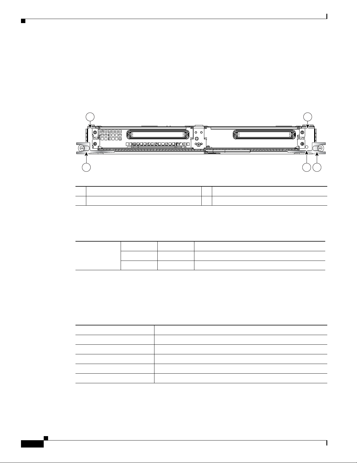
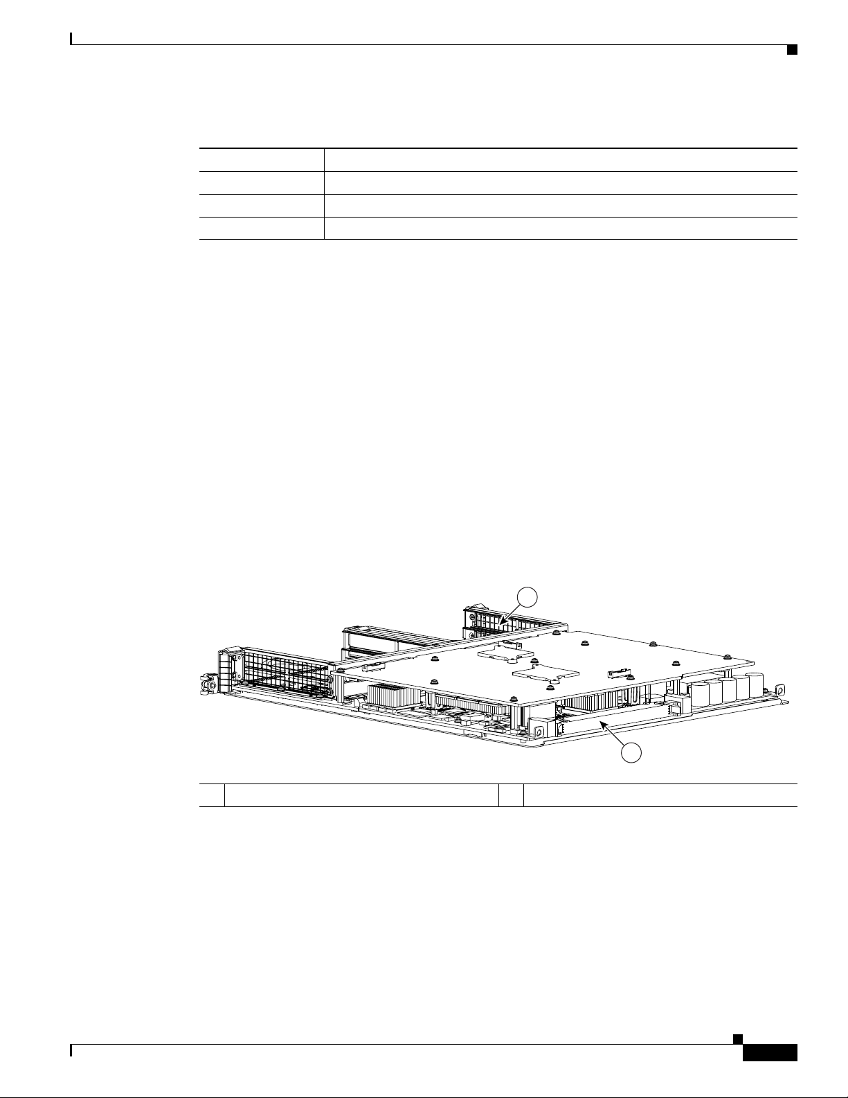
The main Cisco XR 12000 SIP-600 board components are shown in Figure 1-1.
Figure 1-1 Cisco XR 12000 SIP-600 Board—Rear View
1 SPA enclosure 2 Backplane connector
OL-17438-04
Cisco XR 12000 Series Router SIP and SPA Hardware Installation Guide
1-5
Page 18
Cisco XR 12000 SIP-600 Overview
STATUS
1
0
12000-SIP-600
116871
3
1 2
3
4
Cisco XR 12000 SIP-600 LEDs
The Cisco XR 12000 SIP-600 supports 2 single-width, double-height SPAs, 2 single-width,
single-height SPAs, or 1 dual-width, double-height SPA. The Cisco
one Status LED.
SPAs.
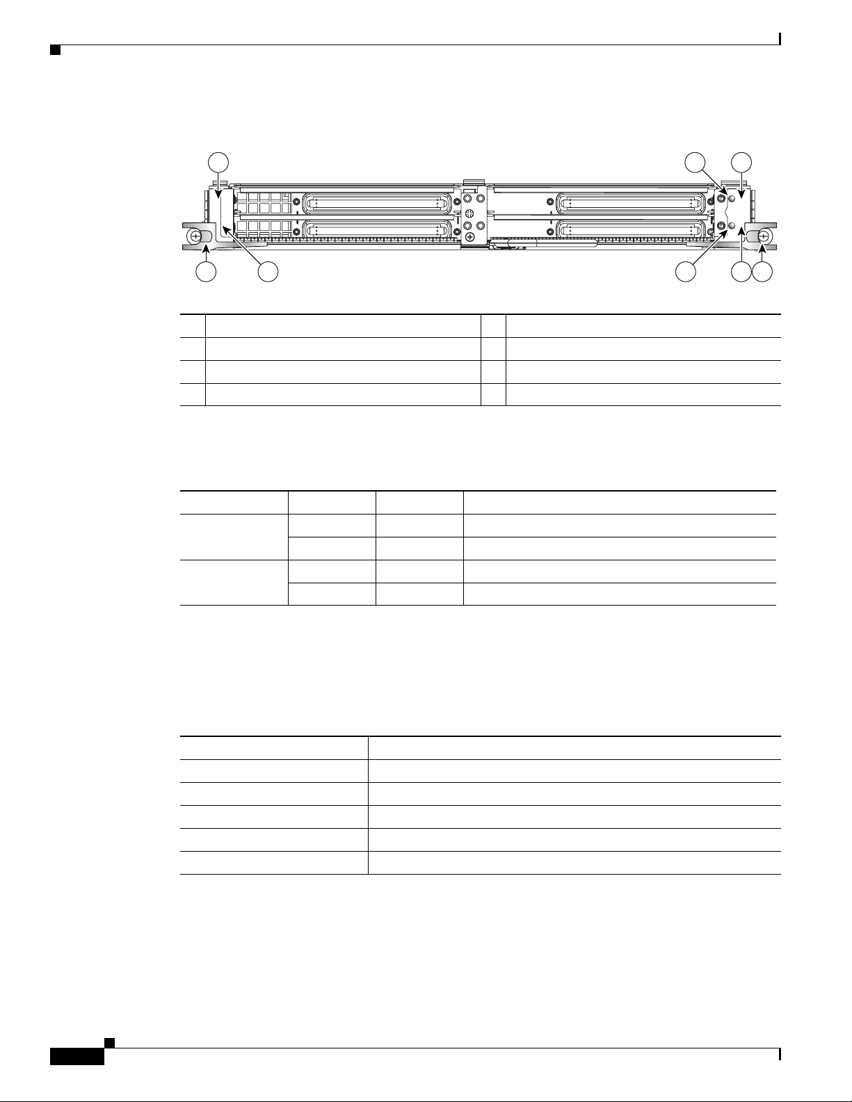
Figure 1-2 Cisco XR 12000 SIP-600 Face Plat e
Figure 1-2 shows the Cisco 12000 SIP-600 face plate wi th 2 single-width, single-heigh t
Chapter 1 Overview: Cisco XR 12000 Series Router SPA Interface Processors
XR 12000 SIP-600 face plate has
1 SPA subslot 0 3 Ejector Levers
2 SPA subslot 1 4 Status LED
The Cisco XR 12000 SIP-600 LEDs are described in Table 1-4.
Table 1-4 Cisco XR 12000 SIP-600 LEDs
LED Label Color State Meaning
Status Yellow On SIP is powered and IOS is loading.
Green On SIP is active.
Cisco XR 12000 SIP-600 Physical Specifications
The Cisco XR 12000 SIP-600 physical specifications are shown in the following table.
Table 1-5 Cisco XR 12000 SIP-600 Physi c a l Specifications
Description Specifications
Physical dimensions Occupies one line card slot on a Cisco 12000 Series Router
Shipping weight 10kg
Operating temperature 32 to 104°F (0 to 40°C)
Relative humidity 10 to 90 percent, noncondensing
Storage temperature –4 to 149°F (–20 to 65°C)
SPA Subslot Numbering on the Cisco XR 12000 SIP-600
The Cisco XR 12000 SIP-600 accepts 2 sin gle-width SPAs or 1 dual-width SPA.
Cisco XR 12000 Series Router SIP and SPA Hardware Installation Guide
1-6
OL-17438-04
Page 19

Chapter 1 Overview: Cisco XR 12000 Series Router SPA Interface Processors
12000-SIP-600
0
116872
STATUS
S
P
A
-1
X
T
E
N
G
E
-X
F
P
-A
A
C
T
IV
E
/
L
IN
K
S
P
A
1
0
X
1
G
E
-A
S
T
A
T
U
S
4
9
3
8
2
7
1
6
0
5
A
/L
A
/L
A
/L
A
/L
A
/L
A
/L
A
/L
A
/L
A
/L
A
/L
1
2
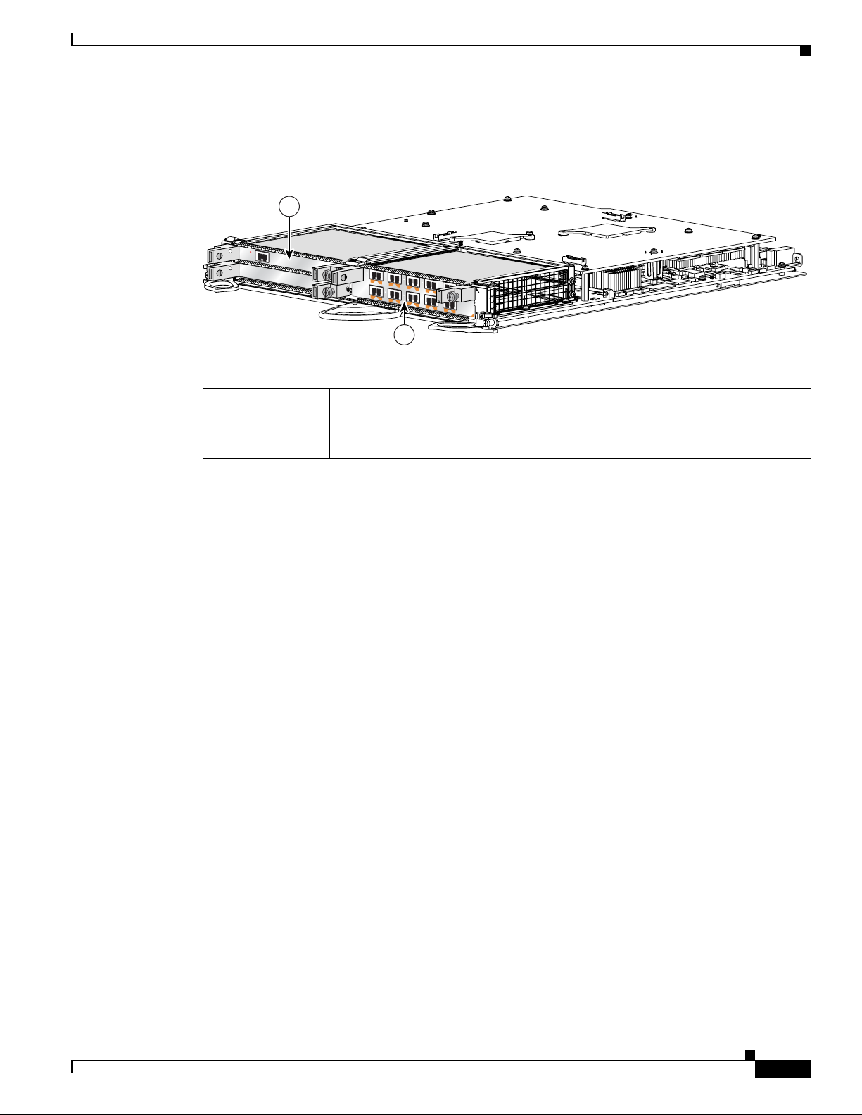
Figure 1-3 shows a Cisco XR 12000 SIP-600 with 2 SPAs installed. The left SPA slot is subslot 0 and
the right SPA slot is subslot 1. If one dual-width SPA is installed, it is recognized as being in subslot 0.
Figure 1-3 Subslot Locations for the 1-Port 10-Gigabit Ethernet SPA
Table 1-6 Subslot Locations for the 1-Port 10-Gigabit Ethernet SPA
Call Out Number Description
1 Subslot 0
2 Subslot 1
Cisco XR 12000 SIP-600 Overview
SPA Interface Addresses on the Cisco XR 12000 SIP-600
A Cisco 12000 Series Router identifies a SP A interf ace address by its SIP slot number, SPA subslot, and
port number on the SPA, in the format slot/subslot/port. Subslots and ports are numbered starting from
0, so each Cisco
address of a 1-port SPA located in the second SIP subslot, where the SIP is inserted int o router line card
slot 3 is 3/1/0.
SPA and the 10-Port Gigabit Ethernet SPA.
XR 12000 SIP-600 has two subslots 0 (left) and 1 (right). For ex ample, the interface
Figure 1-4 shows the slot, subslot, and port locations for the 1-Port 10-Gigabit Ethernet
OL-17438-04
Cisco XR 12000 Series Router SIP and SPA Hardware Installation Guide
1-7
Page 20
Cisco XR 12000 SIP-401 Overview
ACTIVE
0
CARR
IER
RX PKT
ACTIVE
1
CARRIER
RX PKT
ACTIVE
2
CARRIER
RX PKT
ACTIVE
3
CARRIER
RX PKT
Q OC-3/STM-POS
ACTIVE
0
CAR
RIER
RX PKT
ACTIVE
1
CARR
IER
RX PKT
ACTIVE
2
CARRIER
RX PKT
ACTIVE
3
CARRIER
RX PKT
Q OC-3/STM-POS
A
C
T
IV
E
C
A
R
R
IE
R
R
X
P
K
T
OC-48/STM-16-SCPOS
E
JE
C
T
ACT
SIG
ACT
SIG
SLOT-1
SLOT-0
CONSOLE ETH 2AUX
R
E
S
E
T
PERFORMANCE ROUTE PROCESSOR 2
BITS 1BITS 0
DATA
LINK
DATA
LINK
ETH 1ETH 0
E
J
E
C
T
ACT
SIG
ACT
SIG
SLOT-1
SLOT-0
CONSOLE ETH 2AUX
R
E
S
E
T
PERFORMANCE ROUTE PROCESSOR 2
BITS 1BITS 0
DATA
LINK
DA
TA
LINK
ETH 1ETH 0
ALARM A
ALARM B
A
A
M
BUS
MI
NO
R
B
FA
IL
ENABLE
M
AJ
O
R
C
RIT
IC
A
L
B
0
CSC
1
0
SFC
1
2
3
4
129009
S
T
A
T
U
S
ACTIVE/LIN
K
SPA-1XTENGE-XFP-A
1
2
3
Figure 1-4 Slot, Subslot, and Port Locations for the 1-Port 10-Gigabit Ethernet SPA and the
Chapter 1 Overview: Cisco XR 12000 Series Router SPA Interface Processors
10-Port Gigabit Ethernet SPA.
Table 1-7 Slot and Port Locations for the 1-Port 10-Gigabit Ethernet SPA
Call Out Number Description
1 Slot 3
2 Subslot 0, Port 3/0/0
3 Subslot 1, Ports 3/1/0 to 3/1/9
Cisco XR 12000 SIP-401 Overview
The following sections describe the Cisco XR 12000 SIP-401:
• Cisco XR 12000 SIP-401 Board Com ponents, pa ge 1-9
• Cisco XR 12000 SIP-401 LEDs, page 1-9
• Cisco XR 12000 SIP-401 Physical Specifications, page 1-10
• SPA Slot Numbering on the Cisco XR 12000 SIP-401, page 1-10
• SPA Interface Addresses on the Cisco XR 12000 SIP-401, page 1-11
Cisco XR 12000 Series Router SIP and SPA Hardware Installation Guide
1-8
OL-17438-04
Page 21
Chapter 1 Overview: Cisco XR 12000 Series Router SPA Interface Processors
122074
1
2
1
3
0
2
12000-SIP-400
158211
RATE
5 54
1 2
3 7
6
STATUS
Cisco XR 12000 SIP-401 Board Components
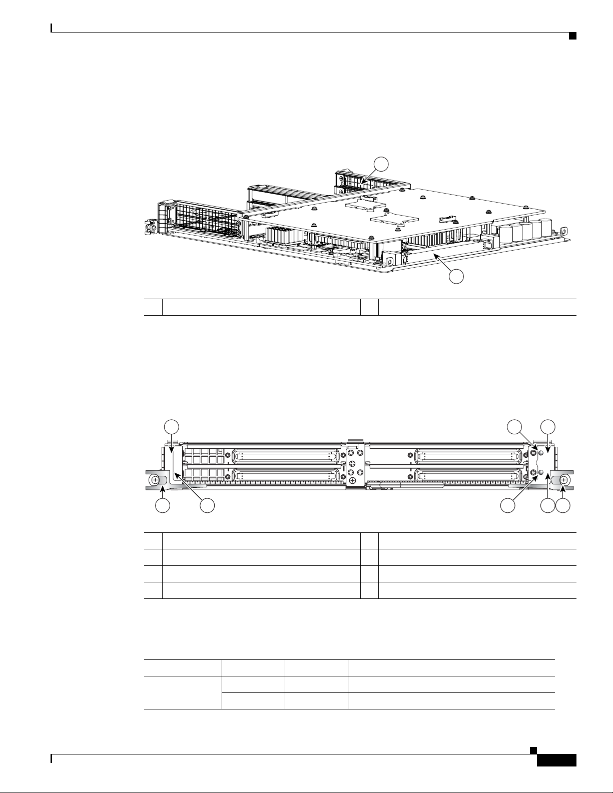
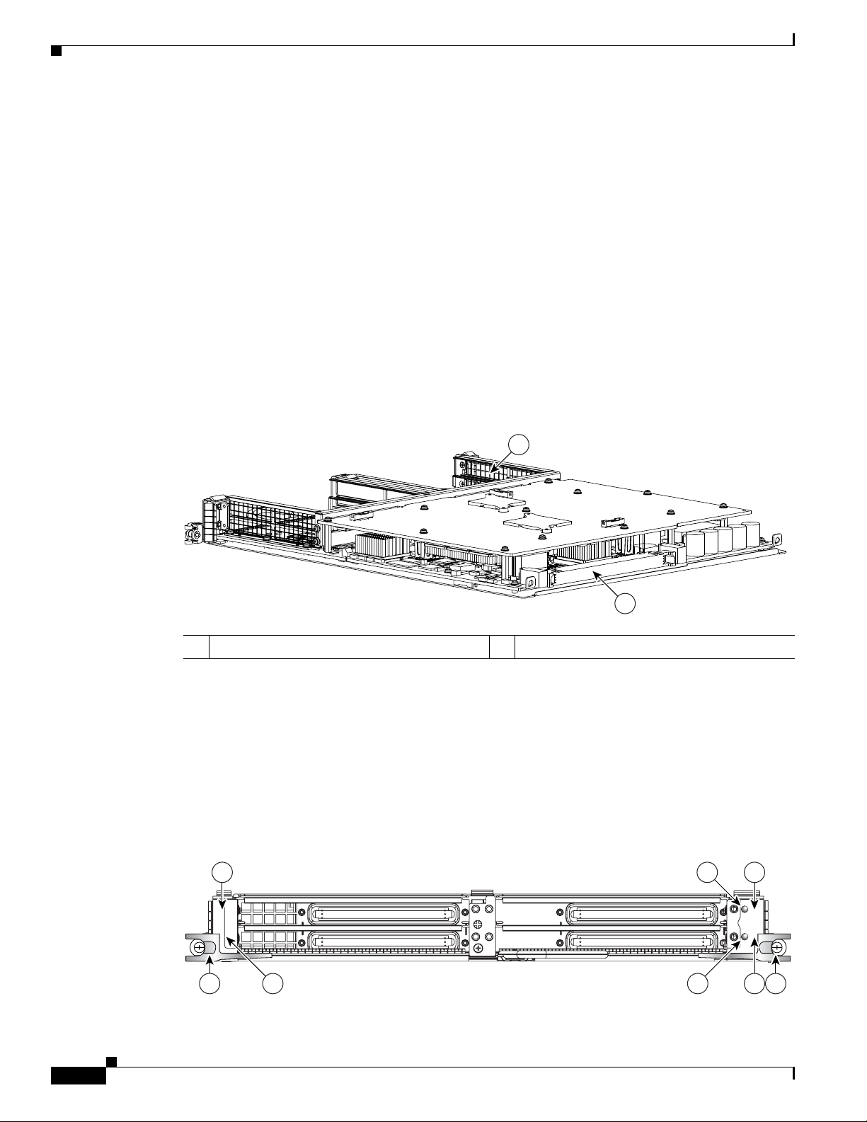
The main Cisco XR 12000 SIP-401 board components are shown in Figure 1-5.
Figure 1-5 Cisco XR 12000 SIP-401 Board—Rear View
1 SPA enclosure 2 Backplane connector
Cisco XR 12000 SIP-401 Overview
Cisco XR 12000 SIP-401 LEDs
The Cisco XR 12000 SIP-401 has two LEDs, as shown in Figure 1-6.
Figure 1-6 Cisco XR 12000 SIP-401 Face Plate
1 SPA subslot 0 5 Ejector Levers
2 SPA subslot 1 6 Status LED
3 SPA subslot 2 7 Rate LED
4 SPA subslot 3
The Cisco XR 12000 SIP-401 LEDs are described in Table 1-8.
Table 1-8 Cisco XR 12000 SIP-401 LED
LED Label Color State Meaning
Status Yellow On IOS is loaded and SIP is ready to be enabled.
OL-17438-04
Green On SIP is active.
Cisco XR 12000 Series Router SIP and SPA Hardware Installation Guide
1-9
Page 22
Chapter 1 Overview: Cisco XR 12000 Series Router SPA Interface Processors
122066
12000-SIP-400
1
3
2
0
STATUS
C/A
TX
RX
1
STATUS
SPA-4XT3/E3
0
A/L
C/A
TX
RX
A/L
C/A
TX
RX
2
A/L
C/A
TX
RX
3
A/L
C/A
TX
RX
1
STATUS
SPA-4XT3/E3
0
A/L
C/A
TX
RX
A/L
C/A
TX
RX
2
A/L
C/A
TX
RX
3
A/L
C/A
TX
RX
1
STATUS
SPA-4XT3/E3
0
A/L
C/A
TX
RX
A/L
C/A
TX
RX
2
A/L
C/A
TX
RX
3
A/L
C/A
TX
RX
1
STATUS
SPA-4XT3/E3
0
A/L
C/A
TX
RX
A/L
C/A
TX
RX
2
A/L
C/A
TX
RX
3
A/L
1
2
3
4
Cisco XR 12000 SIP-401 Overview
Table 1-8 Cisco XR 12000 SIP -401 LED
LED Label Color State Meaning
Rate Off Off SIP is SIP-401 or SIP-501.
Green On SIP is SIP-601.
Cisco XR 12000 SIP-401 Physical Specifications
The Cisco XR 12000 SIP-401 physical specifications are shown in the following table.
Table 1-9 Cisco XR 12000 SIP-401 Physical Specifications
Description Specifications
Physical dimensions Occupies one line card slot on a Cisco 12000 Series Router
Shipping weight 10 kg
Operating temperature 32 to 104°F (0 to 40°C)
Relative humidity 10 to 90 percent, noncondensing
Storage temperature –4 to 149°F (–20 to 65°C)
SPA Slot Numbering on the Cisco XR 12000 SIP-401
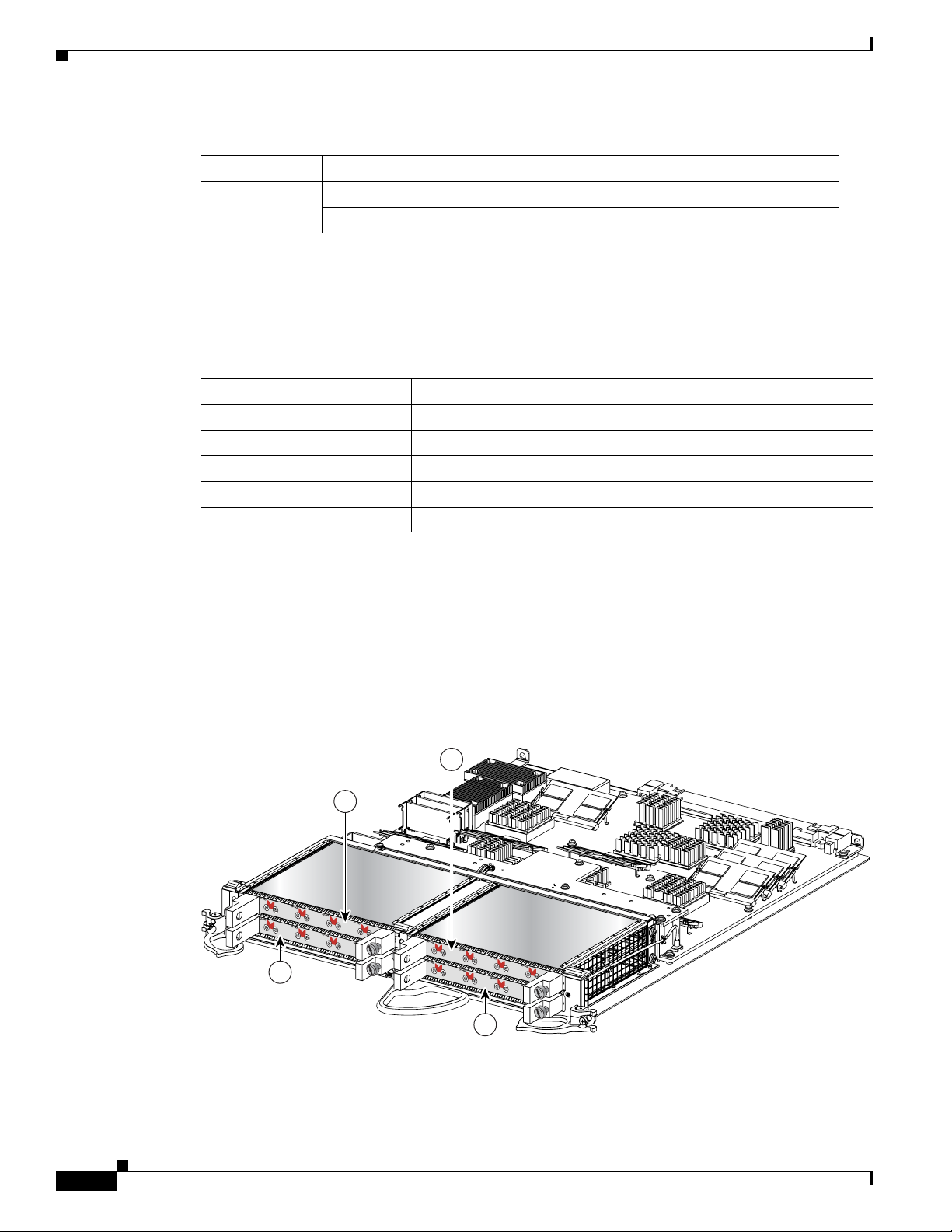
The Cisco XR 12000 SIP-401 accepts 4 single-width, single-height SPAs.
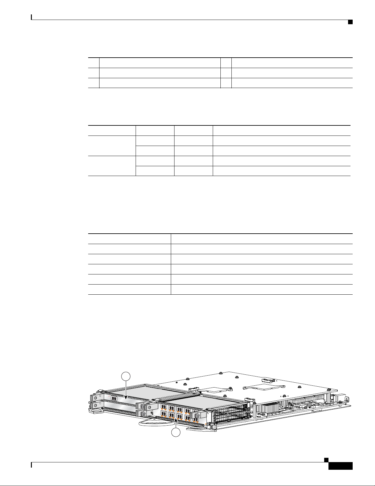
Figure 1-7 shows a Cisco XR 12000 SIP-401 with 4 SPAs installed. The top leftmost SPA slot is subslot
0; the top rightmost SPA slot is subslot 1; the bottom leftmost SPA slot is subslot 2; the bottom rightmost
SPA slot is subslot 3.
Figure 1-7 Cisco XR 12000 SIP-401 with SPAs Installed
1-10
Cisco XR 12000 Series Router SIP and SPA Hardware Installation Guide
OL-17438-04
Page 23
Chapter 1 Overview: Cisco XR 12000 Series Router SPA Interface Processors
ACTIVE
0
CARRIER
RX PKT
ACTIVE
1
C
ARRIER
RX PKT
ACTIVE
2
CAR
RIER
RX PKT
A
CTIVE
3
CARRIER
RX PKT
Q OC-3/STM-POS
AC
TIVE
0
CARRIER
RX PKT
ACTIVE
1
C
ARRIER
RX PKT
ACTIVE
2
CAR
RIER
RX PKT
AC
TIVE
3
CARRIER
R
X PKT
Q OC-3/STM-POS
A
C
T
IV
E
C
A
R
R
IE
R
R
X
P
K
T
OC-48/STM-16-SCPOS
E
J
E
C
T
ACT
SIG
ACT
SIG
SLOT-1
SLOT-0
CONSOLE ETH 2AUX
R
E
S
E
T
PERFORMANCE ROUTE PROCESSOR 2
BITS 1BITS 0
DATA
LINK
DATA
LINK
ETH 1ETH 0
E
J
E
C
T
ACT
SIG
ACT
SIG
SLOT-1
SLOT-0
CONSOLE ETH 2AUX
R
E
S
E
T
PERFORMANCE ROUTE PROCESSOR 2
BITS 1BITS 0
DATA
LINK
DATA
LINK
ETH 1ETH 0
ALARM A
ALARM B
A
A
MBUS
M
INOR
B
FAIL
ENABLE
MAJ
O
R
C
RITICA
L
B
0
CSC
1
0
SFC
1
2
3
4
129102
S
T
A
T
U
S
1
1
2
0
0
0
-S
IP
-6
0
0
0
S
T
A
T
U
S
ACTIVE/LINK
SPA-1XTENGE-XFP-A
C
/A
T
X
R
X
1
S
TA
T
US
SPA-4XCT3/DS0
0
A
/L
C
/A
T
X
R
X
A
/L
C
/A
T
X
R
X
2
A
/L
C
/A
T
X
R
X
3
A
/L
C
/A
T
X
R
X
1
ST
A
T
US
SPA-4XCT3/DS0
0
A
/L
C
/A
T
X
R
X
A
/L
C
/A
T
X
R
X
2
A
/L
C
/A
T
X
R
X
3
A
/L
C
/A
T
X
R
X
1
S
TA
TU
S
SPA-4XCT3/DS0
0
A
/
L
C
/A
T
X
R
X
A
/L
C
/A
T
X
R
X
2
A
/L
C
/A
T
X
R
X
3
A
/L
C
/A
T
X
R
X
1
STA
TU
S
SPA-4XCT3/DS0
0
A
/L
C
/A
T
X
R
X
A
/L
C
/A
T
X
R
X
2
A
/L
C
/A
T
X
R
X
3
A
/L
4
2
1
5
3
1 SPA subslot 0 3 SPA subslot 2
2 SPA subslot 1 4 SPA subslot 3
SPA Interface Addresses on the Cisco XR 12000 SIP-401
A Cisco 12000 Series Router identifies a SP A interf ace address by its SIP slot number, SPA subslot, and
port number on the SPA, in the format slot/subslot/port. Subslots and ports are numbered starting from
0, so each Cisco
example, the interface address of the seco nd port on a 4-port SPA located in the first SIP subslot, where
the SIP is inserted into router line card slot 6 is 6/0/1.
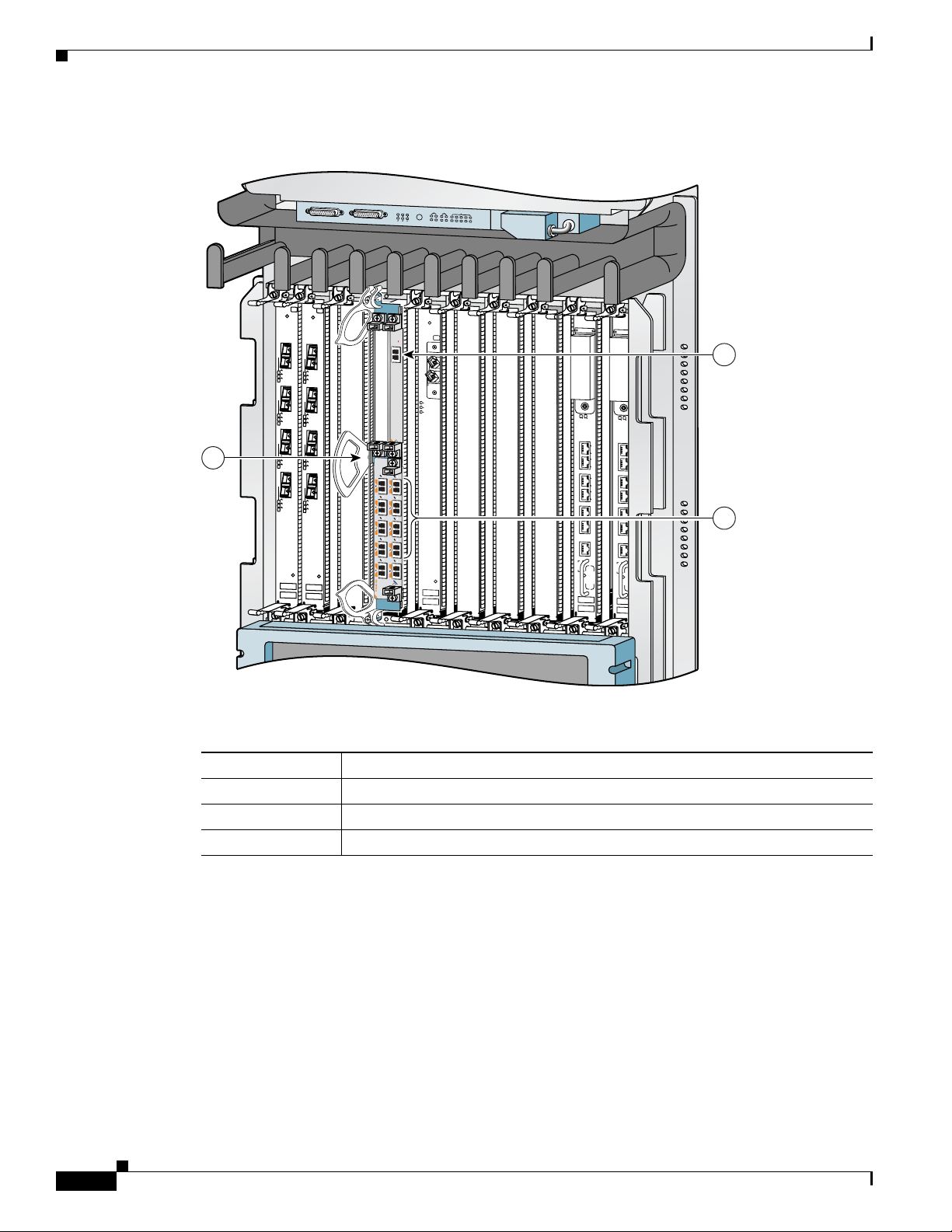
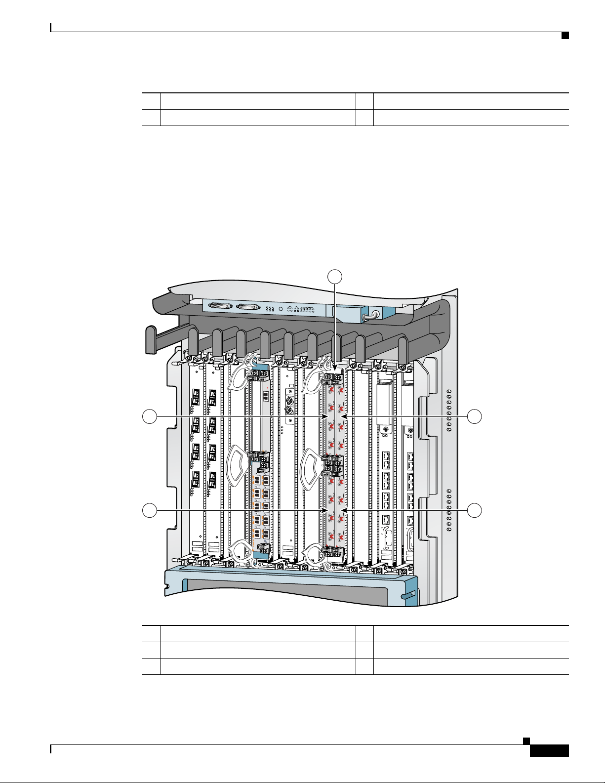
Figure 1-8 Cisco 12000 Series Router with Cisco XR 12000 SIP-401 Installed
XR 12000 SIP-401 has four subslots. A 4-port SPA would have ports 0 to 3. For
Cisco XR 12000 SIP-401 Overview
OL-17438-04
1 Router slot number 6 4 SPA subslot 2 with ports 6/2/0 to 6/2/3
2 SPA subslot 0 with ports 6/0/0 to 6/0/3 5 SPA subslot 3 with ports 6/3/0 to 6/3/3
3 SPA subslot 1 with ports 6/1/0 to 6/1/3
Cisco XR 12000 Series Router SIP and SPA Hardware Installation Guide
1-11
Page 24
Chapter 1 Overview: Cisco XR 12000 Series Router SPA Interface Processors
122074
1
2
1
3
0
2
12000-SIP-400
158211
RATE
5 54
1 2
3 7
6
STATUS
Cisco XR 12000 SIP-501 Overview
Cisco XR 12000 SIP-501 Overview
The following sections describe the Cisco XR 12000 SIP-501:
• Cisco XR 12000 SIP-501 Board Com ponents, pa ge 1-12
• Cisco XR 12000 SIP-501 LEDs, page 1-12
• Cisco XR 12000 SIP-501 Physical Specifications, page 1-13
• SPA Subslot Numbering on the Cisco XR 12000 SIP-501, page 1-13
• SPA Interface Addresses on the Cisco XR 12000 SIP-501, page 1-14
Cisco XR 12000 SIP-501 Board Components
The main Cisco XR 12000 SIP-501 board components are shown in Figure 1-9.
Figure 1-9 Cisco XR 12000 SIP-501 Board—Rear View
1 SPA enclosure 2 Backplane connector
Cisco XR 12000 SIP-501 LEDs
The Cisco XR 12000 SIP-501 supports 2 single-width, double-height SPAs, 2 single-width,
single-height SPAs, or 1 dual-width, double-height SPA. The Cisco
one Status LED.
single-height SPAs.
Figure 1-10 Cisco XR 12000 SIP-501 Face Plate
Cisco XR 12000 Series Router SIP and SPA Hardware Installation Guide
1-12
Figure 1-10 shows the Cisco XR 12000 SIP-501 face plate with 4 single-width,
XR 12000 SIP-501 face plate has
OL-17438-04
Page 25
Chapter 1 Overview: Cisco XR 12000 Series Router SPA Interface Processors
12000-SIP-600
0
116872
STATUS
S
P
A
-1
X
T
E
N
G
E
-X
F
P
-A
A
C
T
IV
E
/
L
IN
K
S
P
A
1
0
X
1
G
E
-
A
S
T
A
T
U
S
4
9
3
8
2
7
1
6
0
5
A
/L
A
/L
A
/L
A
/L
A
/L
A
/L
A
/L
A
/L
A
/L
A
/L
1
2
1 SPA subslot 0 4 SPA subslot 3
2 SPA subslot 1 5 Ejector Levers
3 SPA subslot 2 6 Status LED
The Cisco XR 12000 SIP-501 LEDs are described in Table 1-10.
Table 1-10 Cisco XR 12000 SIP-501 LEDs
LED Label Color State Meaning
Status Yellow On IOS is loaded and SIP is ready to be enabled.
Green On SIP is active.
Rate Off Off SIP is SIP-401 or SIP-501.
Green On SIP is SIP-601.
Cisco XR 12000 SIP-501 Overview
Cisco XR 12000 SIP-501 Physical Specifications
The Cisco XR 12000 SIP-501 physical specifications are shown in the following table.
Table 1-11 Cisco XR 12000 SIP-501 Physical Specifications
Description Specifications
Physical dimensions Occupies one line card slot on a Cisco 12000 Series Router
Shipping weight 10kg
Operating temperature 32 to 104°F (0 to 40°C)
Relative humidity 10 to 90 percent, noncondensing
Storage temperature –4 to 149°F (–20 to 65°C)
SPA Subslot Numbering on the Cisco XR 12000 SIP-501
The Cisco XR 12000 SIP-501 accepts up to 4 single-width SPAs or 1 dual-width SPA.
Figure 1-11 shows a Cisco XR 12000 SIP-501 with 2 SPAs installed. The left SPA slot is subslot 0 and
the right SPA slot is subslot 1. If one dual-width SPA is installed, it is recognized as being in subslot 0.
Figure 1-11 Subslot Locations for the 1-Port 10-Gigabit Ethernet SPA
OL-17438-04
Cisco XR 12000 Series Router SIP and SPA Hardware Installation Guide
1-13
Page 26
Chapter 1 Overview: Cisco XR 12000 Series Router SPA Interface Processors
ACTIVE
0
CARRIER
RX PKT
ACTIVE
1
CARRIER
RX PKT
ACTIVE
2
CARRIER
RX PKT
ACTIVE
3
CARRIER
RX PKT
Q OC-3/STM-POS
ACTIVE
0
CARRIER
RX PKT
ACTIVE
1
CARRIER
RX PKT
AC
TIVE
2
CAR
RIER
RX PKT
ACTIVE
3
CARRIER
RX PKT
Q OC-3/STM-POS
A
C
T
IV
E
C
A
R
R
IE
R
R
X
P
K
T
OC-48/STM-16-SCPOS
E
JE
C
T
ACT
SIG
ACT
SIG
SLOT-1
SLOT-0
CONSOLE ETH 2AUX
R
E
S
E
T
PERFORMANCE ROUTE PROCESSOR 2
BITS 1BITS 0
DA
TA
LINK
DATA
LINK
ETH 1ETH 0
E
J
E
C
T
ACT
SIG
ACT
SIG
SLOT-1
SLOT-0
CONSOLE ETH 2AUX
R
E
S
E
T
PERFORMANCE ROUTE PROCESSOR 2
BITS 1BITS 0
DATA
LINK
DATA
LINK
ETH 1ETH 0
ALARM A
ALARM B
A
A
M
BUS
M
IN
O
R
B
FAIL
ENABLE
M
AJO
R
CR
ITICA
L
B
0
CSC
1
0
SFC
1
2
3
4
129009
S
T
A
T
U
S
ACTIVE/LINK
SPA-1XTENGE-XFP-A
1
2
3
Cisco XR 12000 SIP-501 Overview
Table 1-12 Subslot Locations for the 1-Port 10-Gigabit Ethernet SPA
Call Out Number Description
1 Subslot 0
2 Subslot 1
SPA Interface Addresses on the Cisco XR 12000 SIP-501
A Cisco 12000 Series Router identifies a SP A interf ace address by its SIP slot number, SPA subslot, and
port number on the SPA, in the format slot/subslot/port. Subslots and ports are numbered starting from
0, so each Cisco
address of a 1-port SPA located in the second SIP subslot, where the SIP is inserted int o router line card
slot 3 is 3/1/0.
SPA and the 10-Port Gigabit Ethernet SPA.
Figure 1-12 Slot, Subslot, and Port Locations for the 1-Port 10-Gigabit Ethernet SPA and the
XR 12000 SIP-601 has two subslots 0 (left) and 1 (right). For example, the interface
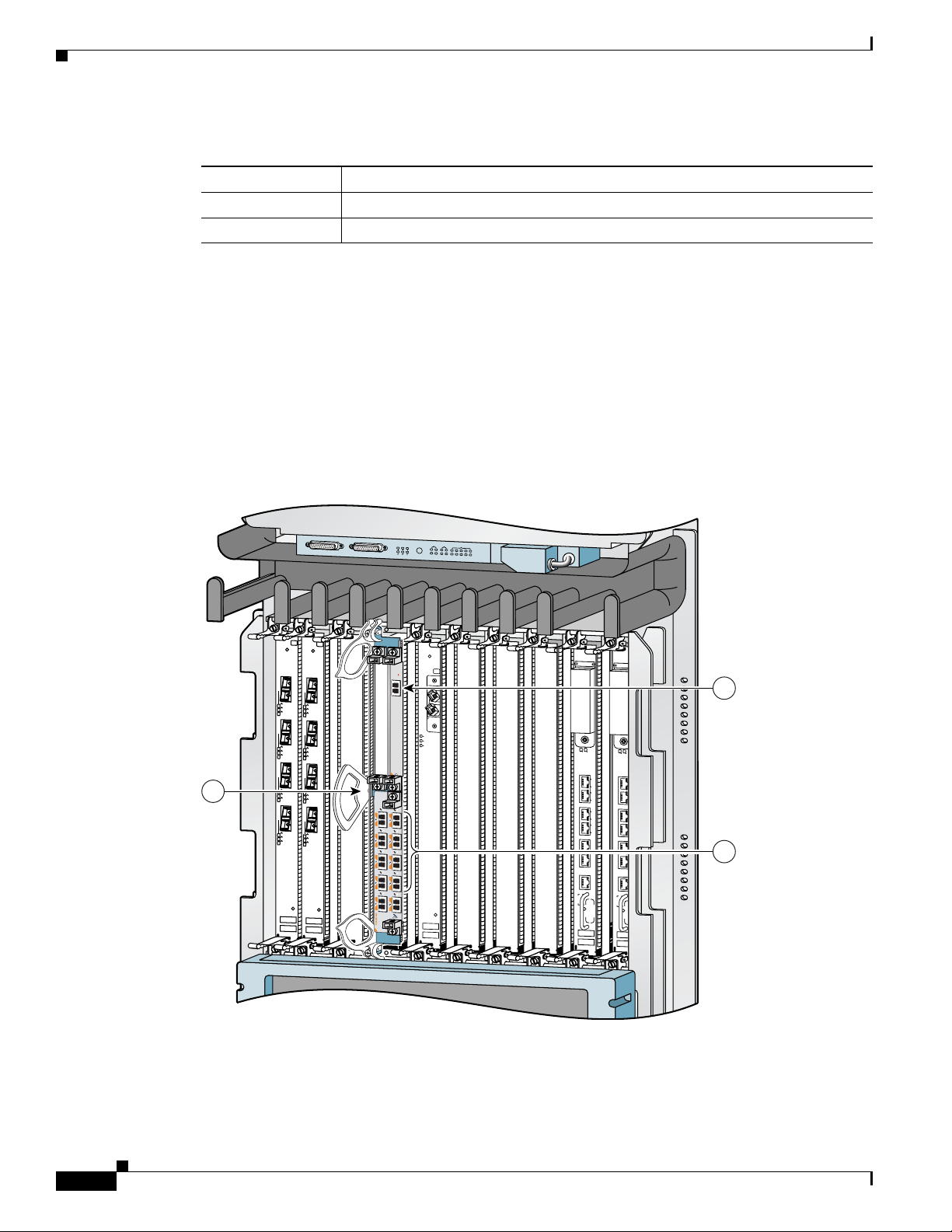
Figure 1-12 shows the slot, subslot, and port locations for th e 1-Po rt 10-Gig abit Ethernet
10-Port Gigabit Ethernet SPA.
Cisco XR 12000 Series Router SIP and SPA Hardware Installation Guide
1-14
OL-17438-04
Page 27
Chapter 1 Overview: Cisco XR 12000 Series Router SPA Interface Processors
122074
1
2
Table 1-13 Slot and Port Locations for the 1-Port 10-Gigabit Ethernet SPA
Call Out Number Description
1 Slot 3
2 Subslot 0, Port 3/0/0
3 Subslot 1, Ports 3/1/0 to 3/1/9
Cisco XR 12000 SIP-601 Overview
The following sections describe the Cisco XR 12000 SIP-601:
• Cisco XR 12000 SIP-601 Board Com ponents, pa ge 1-15
• Cisco XR 12000 SIP-601 LEDs, page 1-15
• Cisco XR 12000 SIP-601 Physical Specifications, page 1-16
• SPA Subslot Numbering on the Cisco XR 12000 SIP-601, page 1-16
• SPA Interface Addresses on the Cisco XR 12000 SIP-601, page 1-17
Cisco XR 12000 SIP-601 Overview
Cisco XR 12000 SIP-601 Board Components
The main Cisco XR 12000 SIP-601 board components are shown in Figure 1-13.
Figure 1-13 Cisco XR 12000 SIP-601 Board—Rear View
1 SPA enclosure 2 Backplane connector
Cisco XR 12000 SIP-601 LEDs
The Cisco XR 12000 SIP-601 supports 4 single-height SPAs (the aggregate throughput should not
exceed 2 full-rate SPAs); 2 double-height SPAs; 1 dual-width, double-height SPA, or a combination of
single-height and double-height SPAs. The Cisco
Figure 1-14 shows the Cisco XR 12000 SIP-601 face plate with 4 single-width, single-height SPAs.
XR 12000 SIP-601 face plate has one Status LED.
OL-17438-04
Cisco XR 12000 Series Router SIP and SPA Hardware Installation Guide
1-15
Page 28
Cisco XR 12000 SIP-601 Overview
1
3
0
2
12000-SIP-400
158211
RATE
5 54
1 2
3 7
6
STATUS
Figure 1-14 Cisco XR 12000 SIP-601 Face Plate
1 SPA subslot 0 5 Ejector Levers
2 SPA subslot 1 6 Status LED
3 SPA subslot 2 7 Rate LED
4 SPA subslot 3
The Cisco XR 12000 SIP-601 LEDs are described in Table 1-14.
Chapter 1 Overview: Cisco XR 12000 Series Router SPA Interface Processors
Table 1-14 Cisco XR 12000 SIP-601 LEDs
LED Label Color State Meaning
Status Yellow On IOS is loaded and SIP is ready to be enabled.
Green On SIP is active.
Rate Off Off SIP is SIP-401 or SIP-501.
Green On SIP is SIP-601.
Cisco XR 12000 SIP-601 Physical Specifications
The Cisco XR 12000 SIP-601 physical specifications are shown in the following table.
Table 1-15 Cisco XR 12000 SIP-601 Physical Specifications
Description Specifications
Physical dimensions Occupies one line card slot on a Cisco 12000 Series Router
Shipping weight 10kg
Operating temperature 32 to 104°F (0 to 40°C)
Relative humidity 10 to 90 percent, noncondensing
Storage temperature –4 to 149°F (–20 to 65°C)
SPA Subslot Numbering on the Cisco XR 12000 SIP-601
The Cisco XR 12000 SIP-601 accepts 4 single-height SPAs (the aggregate throughput should not e xceed
2 full-rate SPAs); 2 double-height SPAs; 1 dual-width, double-height SPA, or a combination of
Cisco XR 12000 Series Router SIP and SPA Hardware Installation Guide
single-height and double-height SPAs.
1-16
OL-17438-04
Page 29
Chapter 1 Overview: Cisco XR 12000 Series Router SPA Interface Processors
12000-SIP-600
0
116872
STATUS
S
P
A
-1
X
T
E
N
G
E
-X
F
P
-A
A
C
T
IV
E
/
L
IN
K
S
P
A
1
0
X
1
G
E
-A
S
T
A
T
U
S
4
9
3
8
2
7
1
6
0
5
A
/L
A
/L
A
/L
A
/L
A
/L
A
/L
A
/L
A
/L
A
/L
A
/L
1
2
Figure 1-15 shows a Cisco XR 12000 SIP-601 with 2 SPAs installed. The left SPA slot is subslot 0 and
the right SPA slot is subslot 1. If one dual-width SPA is installed, it is recognized as being in subslot 0.
Figure 1-15 Subslot Locations for the 1-Port 10-Gigabit Ethernet SPA
Table 1-16 Subslot Locations for the 1-Port 10-Gigabit Ethernet SPA
Call Out Number Description
1 Subslot 0
2 Subslot 1
Cisco XR 12000 SIP-601 Overview
SPA Interface Addresses on the Cisco XR 12000 SIP-601
A Cisco 12000 Series Router identifies a SP A interf ace address by its SIP slot number, SPA subslot, and
port number on the SPA, in the format slot/subslot/port. Subslots and ports are numbered starting from
0, so each Cisco
address of a 1-port SPA located in the second SIP subslot, where the SIP is inserted int o router line card
slot 3 is 3/1/0.
SPA and the 10-Port Gigabit Ethernet SPA.
XR 12000 SIP-601 has two subslots 0 (left) and 1 (right). For ex ample, the interface
Figure 1-16 shows the slot, subslot, and port locations for the 1-Port 1 0-Gigabi t Et hernet
OL-17438-04
Cisco XR 12000 Series Router SIP and SPA Hardware Installation Guide
1-17
Page 30

Cisco XR 12000 SIP-601 Overview
ACTIVE
0
CARR
IER
RX PKT
ACTIVE
1
CARRIER
RX PKT
ACTIVE
2
CARRIER
RX PKT
ACTIVE
3
CARRIER
RX PKT
Q OC-3/STM-POS
ACTIVE
0
CAR
RIER
RX PKT
ACTIVE
1
CARR
IER
RX PKT
ACTIVE
2
CARRIER
RX PKT
ACTIVE
3
CARRIER
RX PKT
Q OC-3/STM-POS
A
C
T
IV
E
C
A
R
R
IE
R
R
X
P
K
T
OC-48/STM-16-SCPOS
E
JE
C
T
ACT
SIG
ACT
SIG
SLOT-1
SLOT-0
CONSOLE ETH 2AUX
R
E
S
E
T
PERFORMANCE ROUTE PROCESSOR 2
BITS 1BITS 0
DATA
LINK
DATA
LINK
ETH 1ETH 0
E
J
E
C
T
ACT
SIG
ACT
SIG
SLOT-1
SLOT-0
CONSOLE ETH 2AUX
R
E
S
E
T
PERFORMANCE ROUTE PROCESSOR 2
BITS 1BITS 0
DATA
LINK
DA
TA
LINK
ETH 1ETH 0
ALARM A
ALARM B
A
A
M
BUS
MI
NO
R
B
FA
IL
ENABLE
M
AJ
O
R
C
RIT
IC
A
L
B
0
CSC
1
0
SFC
1
2
3
4
129009
S
T
A
T
U
S
ACTIVE/LIN
K
SPA-1XTENGE-XFP-A
1
2
3
Figure 1-16 Slot, Subslot, and Port Locations for the 1-Port 10-Gigabit Ethernet SPA and the
Chapter 1 Overview: Cisco XR 12000 Series Router SPA Interface Processors
10-Port Gigabit Ethernet SPA.
Table 1-17 Slot and Port Locations for the 1-Port 10-Gigabit Ethernet SPA
Call Out Number Description
1 Slot 3
2 Subslot 0, Port 3/0/0
3 Subslot 1, Ports 3/1/0 to 3/1/9
Cisco XR 12000 Series Router SIP and SPA Hardware Installation Guide
1-18
OL-17438-04
Page 31

CHAPTER
2
Overview: Cisco XR 12000 Series Router Shared Port Adapters
Revised: December 2012, OL-17438-04
This chapter describes the shared p ort ad apters (SPAs) that are supported on the Cisco XR 12000 Series
Router and contains the following sections:
• SPA Summary, page 2-2
• Bandwidth Oversubscription, page 2-3
• 2-Port and 4-Port T3/E3 Serial SPA Overview, page 2-5
• 2-Port and 4-Port Channelized T3 to DS0 SPA Overview, page 2-7
• 8-Port Channelized T1/E1 SPA Overview, page 2-9
• 8 Port FastEthernet SPA Overview, page 2-11
• 1 Port 10-Gigabit Ethernet SPA Overview, page 2-13
• 2-Port Gigabit Ethernet SPA Overview, page 2-17
• 5-Port Gigabit Ethernet SPA Overview, page 2-22
OL-17438-04
• 10-Port Gigabit Ethernet SPA Overview, page 2-26
• 1-Port Channelized STM-1/OC-3 SPA Overview, page 2-30
• 1-Port Channelized STM-4/OC-12 SPA Overview, page 2-32
• 1-Port OC-192/STM-64 POS SPA Overview, pa ge 2-38
• 1-Port OC-192/STM-64 POS SPA Overview, pa ge 2-38
• 1-Port OC-192 STM-64 POS RPR XFP SPA Overview, page 2-41
• 4-Port OC-3/STM-1 POS SPA Overview, page 2-45
• 8-Port OC-3 STM-1/OC-12 STM-4 POS SPA Overview, page 2-50
• 1-Port OC-12/STM-4 POS SPA Overview, page 2-55
• 1-Port OC-48/STM-16 POS SPA Overview, page 2-58
• 2-Port and 4-Port OC-48/STM-16 POS SPA Overview, page 2-61
• 2-Port OC-48 POS RPR SPA Overview, page 2-6 5
• Cisco XR12000 IPSec VPN SPA Overview, page 2-67
Cisco XR 12000 Series Router SIP and SPA Hardware Installation Guide
2-1
Page 32

Chapter 2 Overview: Cisco XR 12000 Series Router Shared Port Adapters
SPA Summary
• 1-Port and 3-Port Clear Channel OC-3 ATM SPA Overview, page 2-69
• 1-Port Clear Channel OC-12 ATM SPA Overview, page 2-71
• 2-Port Channelized T3/E3 ATM CEoP SPA Overview, page 2-74
• 24-Port Channelized T1/E1/J1 ATM CEoP SPA Overview, page 2-76
• 1-Port Channelized OC-3 ATM CEoP SPA Overview, page 2-82
• 1-Port 10-Gigabit Ethernet DWDM SPA Overview, page 2-83
• 1-Port 10-Gigabit Ethernet WAN PHY SPA Overview, page 2-85
SPA Summary
Table 2-1 shows the summary descriptions of the SPAs that are supported on the Cisco XR 12000 Series
Router.
Table 2-1 Supported SPAs on Cisco XR 12000 Series Routers
Minimum
Hardware
Revision
Product Number Description
Number of
Ports
Minimum IOS
XR Release
SPA-2XT3/E3 2-Port T3/E3 Serial SPA 2 3.3.0 1.0
SPA-4XT3/E3 4-Port T3/E3 Serial SPA 4 3.3.0 1.0
SPA-2XC T3/DS0 2-Port Channelized T3 to DS0 SPA 2 3.3.0 1.0
SPA-4XCT3/DS0 4-Port Channelized T3 to DS0 SPA 4 3.3.0 1.0
SPA-8XCHT1/E1 8-Port Channelized T1/E1 SPA 8 3.6.0 1.0
SPA-8XFE 8-Port FastEthernet SPA 8 3.3.0 1.0
SPA-8X1FE-TX-V2 8-Port Fast Ethernet SPA 8 3.4.0 1.0
SPA-1XTENG E-XFP 1-Port 10-Gigabit Ethernet SPA 1 3.2 1.0
SPA-1X10GE-L-V2 1-Port 10-Gigabit Ethernet SPA 1 3.4.0 1.0
SPA-2X1GE-V2 2-Port Gigabit Ethernet SPA 2 3.4.1 1.0
SPA-5XGE 5-Port Gigabit Ethernet SPA 5 3.2 1.0
SPA-5XGE-V2 5-Port Gigabit Ethernet SPA 5 3.4.0 1.0
SPA-10XGE 10-Port Gigabit Ethernet SPA 10 3.2 1.0
SPA-10X1GE-V 2 10-Port Gigabit Ethernet SPA 10 3.4.0 1.0
SPA-1XCHOC3/DS0 1-Port Channelized STM-1/OC-3 SPA 1 3.5.0 1.0
SPA-1XCHOC12/DS0 1-Port Channelized STM-4/OC-12 SPA 1 3.5.0 1.0
SPA-1XCHOC48/DS3 1-Port Channelized STM-16/OC-48 SPA 1 3.6.0 1.0
SPA-OC192POS 1-Port OC-192/STM-64 POS SPA 1 3.2 1.0
SPA-4XOC3POS 4-Port OC-3/STM-1 POS SPA 4 3.5.0 1.0
SPA-8XOC12-POS 8-Port OC-3 STM-1/OC-12 STM-4 POS SPA 8 3.5.0 1.0
SPA-OC48POS 1-Port OC-48/STM-16 POS SPA 1 3.6.0 1.0
SPA-4XOC48POS 4-Port OC-48/STM-16 POS/RPR SPA 4 3.5.0 1.0
2-2
Cisco XR 12000 Series Router SIP and SPA Hardware Installation Guide
OL-17438-04
Page 33

Chapter 2 Overview: Cisco XR 12000 Series Router Shared Port Adapters
Bandwidth Oversubscription
Table 2-1 Supported SPAs on Cisco XR 12000 Series Routers (continued)
Minimum
Number of
Product Number Description
SPA-2XOC48POS 2-Port OC48-POS/RPR SPA 2 3.3.0 1.0
SPA-IPSEC-2G-2 IPSec VPN SPA - 3.4.0 1.0
SPA-1XOC3-ATM-V2 1-Port Clear Channel OC-3 ATM SPA 1 3.7.0 1.0
SPA-3XOC3-ATM-V2 3-Port Clear Channel OC-3 ATM SPA 3 3.7.0 1.0
SPA-1XOC12-ATM-V2 1-Port Clear Channel OC-12 ATM SPA 1 3.7.0 1.0
SPA-2CHT3-CE-ATM 2-Port Channelized T3/E3 ATM CEoP SPA 2 3.7.0 1.0
SPA-24CHT1-CE-ATM 24-Port Channelized T1/E1/J1 ATM CEoP SPA 24 4.0.1 1.0
SPA-1CHOC3-CE-ATM 1-Port Channelized OC-3 ATM CEoP SPA 1 4.1.1 1.0
SPA-1X10GE-L-IT 1-Port 10-Gigabit Ethernet DWDM SPA 1 4.1.1 1.0
SPA-1X10GE-WL-V2 1-Port 10-Gigabit Ethernet WAN PHY SPA 1 4.3.0 1.0
Ports
Minimum IOS
XR Release
Hardware
Revision
Checking Hardware and Software Compatibility
T o check the minimum softw are requirements of Cisco IOS XR softwar e with the hardw are instal led on
your router, Cisco maintain s the Softw are Adv isor tool on Cisco. com. This t ool does not verify whether
SIPs or SPAs within a system are compatible, but it does provide the minimum Cisco IOS XR
requirements for individual hardware modules or components.
Note Access to this tool is limited to users with Cisco.com login accounts.
To access Software Advisor, click Login at Cisco.com, type “Software Advisor” in the SEARCH box,
and click GO. Click the link for the Softwar e Advi sor tool.
Choose a product family or enter a specific product number to search for the minimum supported
software release needed for your hardware.
Bandwidth Oversubscription
Oversubscribing the bandwidth limit recommendations of a router can result in decreased or degraded
performance. For this reason, it is important to determine the amou nt of bandwi dth used b y the SPAs on
the router and verify that the total bandwidth used by all SPAs does not exceed the recommended
bandwidth limit of the router . The aggre gate throughput should not exceed 2 full-rate SPAs for 10G SIPs.
OL-17438-04
Note The SIP-600 [10G SIP], SIP-401 [2.5G SIP], SIP-501 [5G SIP], and SIP-601 [10G SIP] can support up
to 20G of installed SPAs, but the bandwidth through the engine and the fabric is no more than 10G
(SIP-600 or SIP-601). The bandwidth through the engine and the fabric is no more than 5G for the
SIP-501 and is no more than 2.5G for the SIP-401.
Cisco XR 12000 Series Router SIP and SPA Hardware Installation Guide
2-3
Page 34

Bandwidth Oversubscription
Note In Cisco IOS XR software release 3.9.1 or prior, the full-rate SPAs need to be positioned in bay 0 and 1.
Table 2-2 provides information about the bandwidth for each port (per-port bandwidth) on a SPA, as well
as the cumulative bandwidth (total bandwidth) for all ports available on the SPA.
Table 2-2 SPA Bandwidth Capacity
SPA Per-Port Bandwidth
2-Port Channelized T3 SPA 44.736 Mbps 2 89.47 Mbps
4-Port Channelized T3 SPA 44.736 Mbps 4 178.94 Mbps
2-Port Clear Channel T3/E3 SPA 44.736 Mbps (T3)
4-Port Clear Channel T3/E3 SPA 44.736 Mbps (T3)
8-Port Channelized T1/E1 SPA 1.544 Mbps (T1)
1-Port 10-Gigabit Ethernet SPA 10 Gbps 1 10 Gbps
5-Port Gigabit Ethernet SPA 1 Gbps 5 5 Gbps
10-Port Gigabit Ethernet SPA 1 Gbps 10 10 Gbps
1-Port Channelized STM-1/OC-3 SPA 155.52 Mbps 1 155.52 Mbps
1-Port Channelized STM-4/OC-12 SPA 622.08 Mbps 1 622.08 Mbps
1-Port Channelized STM-16/OC-48 SPA 2.488 Gbps 1 2.488 Gbps
1-Port OC-192/STM-64 POS SPA 9.953 Gbps 1 9.953 Gbps
4-Port OC-3/STM-1 POS SPA 155.52 Mbps 4 622.08 Mb ps
8-Port OC-3 STM-1/OC-12 STM-4 POS SPA 155.52 Mbps or
1-Port OC-12/STM-4 POS SPA 622.08 Mbps 1 622.08 Mbps
1-Port OC-48/STM-16 POS SPA 2.488 Gbps 1 2.488 Gbps
4-Port OC-48/STM-16 POS/RPR SPA 2.488 Gbps 4 10 Gbps
2-Port OC48-POS/RPR SPA 2.488 Gbps 2 4.976 Gbps
1-Port Clear Channel OC-3 ATM SPA 155.52 Mbps 1 155.52 Mbps
3-Port Clear Channel OC-3 ATM SPA 155.52 Mbps 3 466.56 Mbps
1-Port Clear Channel OC-12 ATM SPA 622.08 Mbps 1 622.08 Mbps
2-Port Channelized T3/E3 ATM CEoP SPA 44.210 Mbps
24-Port Channelized T1/E1/J1 ATM CEoP
SPA
1-Port Channelized OC-3 ATM CEoP SPA 155.52 Mbps 1 155.52 Mbps
Chapter 2 Overview: Cisco XR 12000 Series Router Shared Port Adapters
Number
of Ports Total Bandwidth
2 89.47 Mbps (T3)
34.368 Mbps (E3)
34.368 Mbps (E3)
2.048 Mbps (E1)
622.08
Mbps
34.010 Mbps
1.544 Mbps
2.048 Mbps
4 178.94 Mbps (T3)
8 12.35 Mbps (T1)
8 5 Gbps
2 88.42 Mbps
24 37.056 Mbps
68.74 Mbps (E3)
137.47 Mbps (E3)
16.38 Mbps (E1)
1
68.02 Mbps
49.152 Mbps
2-4
Cisco XR 12000 Series Router SIP and SPA Hardware Installation Guide
OL-17438-04
Page 35
Chapter 2 Overview: Cisco XR 12000 Series Router Shared Port Adapters
C/A
TX
RX
1
STATUS
SPA-4XT3/E3
0
A/L
C/A
TX
RX
A/L
C/A
TX
RX
2
A/L
C/A
TX
RX
3
A/L
1
2
3 4 5
116851
Table 2-2 SPA Bandwidth Capacity (continued)
SPA Per-Port Bandwidth
1-Port 10-Gigabit Ethernet DWDM SPA 10 Gbps 1 10 Gbps
1-Port 10-Gigabit Ethernet WAN PHY SPA 10 Gbps 1 10 Gbps
1. Total bandwidth value assumes eight OC-12/STM-4 optics modules.
2-Port and 4-Port T3/E3 Serial SPA Overview
The following sections describe the 2-Port and 4-Port Clear Channel T3/E3 SPA:
• 2-Port and 4-Port Clear Channel T3/E3 SPA LEDs, page 2-5
• 2-Port and 4-Port Clear Channel T3/E3 SPA Interface Specifications, page 2-6
• 2-Port and 4-Port Clear Channel T3/E3 SPA Cables and Connectors, page 2-6
2-Port and 4-Port T3/E3 Serial SPA Overview
Number
of Ports Total Bandwidth
2-Port and 4-Port Clear Channel T3/E3 SPA LEDs
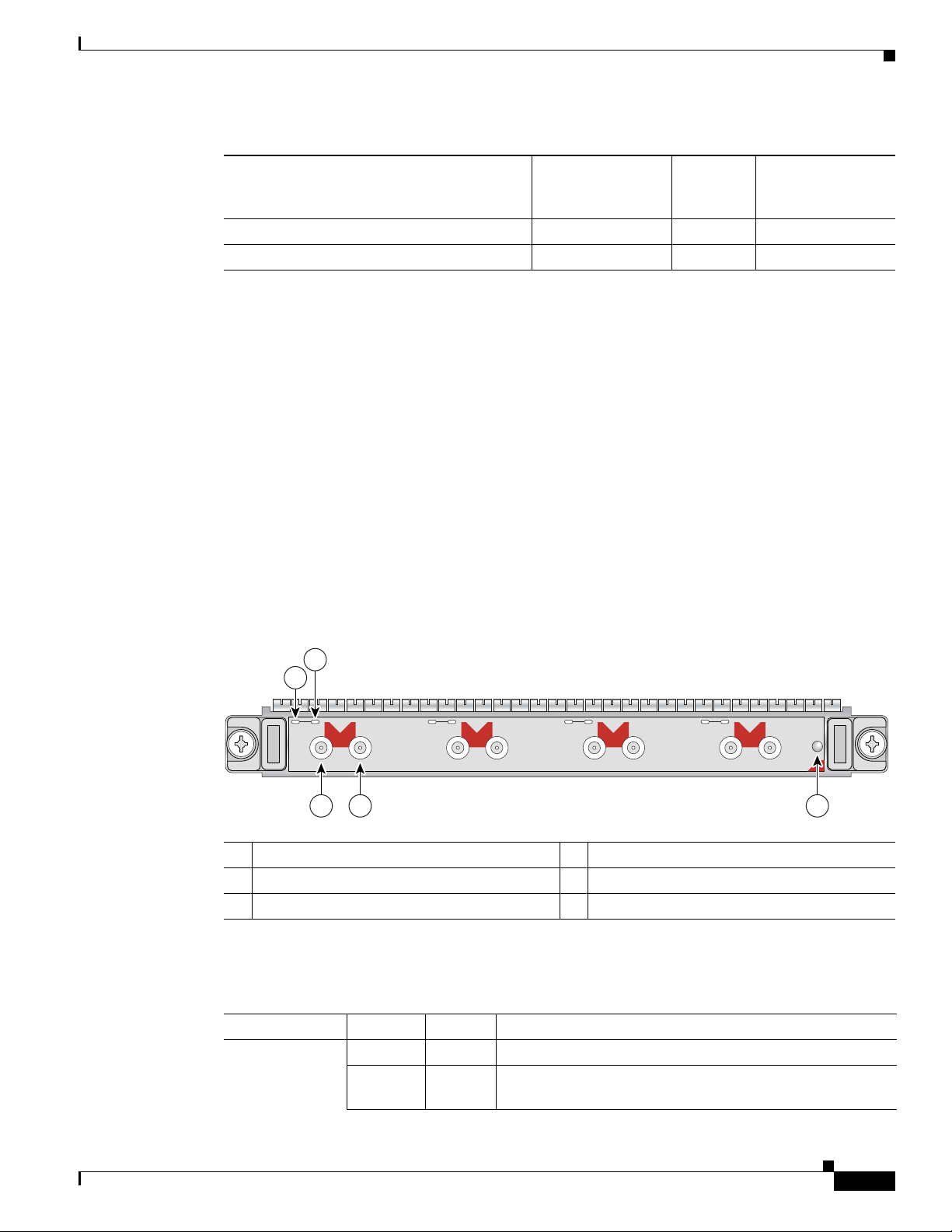
The 2-Port and 4-Port Clear Channel T3/E3 SPA has three types of LEDs: two LEDs for each port on
the SPA, and one STATUS LED, as shown in
Figure 2-1 4-Port Clear Channel T3/E3 SPA Faceplate
1 C/A (Carrier/Alarm) LED 4 RX (Receive) connector
2 A/L (Active Loopback) LED 5 STATUS LED
3 TX (Transmit) connector
Table 2-3 describes the 2-Port and 4-Port Clear Channel T3/E3 SPA LEDs.
Figure 2-1.
Table 2-3 2-Port and 4-Port Clear Channel T3/E3 SPA LEDs
LED Label Color State Meaning
C/A Off Off Port is not enabled by software.
OL-17438-04
Green On Port is enabled by software, and there is a valid E3 or T3
signal without any alarms.
Cisco XR 12000 Series Router SIP and SPA Hardware Installation Guide
2-5
Page 36

Chapter 2 Overview: Cisco XR 12000 Series Router Shared Port Adapters
2-Port and 4-Port T3/E3 Serial SPA Overview
Table 2-3 2-Port and 4-Port Clear Channel T3/E3 SPA LEDs (continued)
LED Label Color State Meaning
Amber On Port is enabled by software, and there is at least one alarm.
A/L Off Off Port is not enabled by software.
Green On Port is enabled by software, and loopback is off.
Amber On Port is enabled by software, and loopback is on.
STATUS Off Off SPA power is off.
Green On SPA is ready and operational.
Amber On SPA power is on and good, and the SPA is being configured.
2-Port and 4-Port Clear Channel T3/E3 SPA Interface Specifications
The framer processes incoming and outgoing T3 (cbit, m13/m23, and unframe) and E3 (g751, g832, and
unframe) frames. The framer operates at T3/E3 line rates (44.736 /34.368 Mbps) depending on the mode
in which it is configured.
Packet data is transported with a user-conf igurable encapsulation (such as Point-to-Point Protocol [PPP]
or High-Level Data Link Control [HDLC]), and is mapped to T3 and E3 frames. The encapsulations add
transport overhead to the packet of data frames before transporting, and are stripped when a packet is
transported to the far end.
The T3/E3 SPA interface is compliant with ANSI and Telco standards. The interface also provides
support for Management Information Base (MIB) RFC 2496 and T1.231.
2-Port and 4-Port Clear Channel T3/E3 SPA Cables and Connectors
The interface connectors on the 2-Port and 4-Port Clear Channel T3/E3 SPA are 75-ohm coaxial Siemax
types, with one connector and cable for transmit (TX) and one for receive (RX).
The following cables can be used with the 2-Port and 4-Port Clear Channel T3/E3 SPA. The cables have
BNC connectors on one end and the Siemax connectors on the other. If similar SPAs are connected
back-to-back, both ends of cable will be Siemax.
• CAB-T3E3-RF-BNC-M (T3 or E3 Cable, 1.0/2.3 RF to BNC-Mal e, 10 feet)
• CAB-T3E3-RF-BNC-F (T3 or E3 Cable, 1.0/2.3 RF to BNC-Female, 10 feet)
• CAB-T3E3-RF-OPEN (T3 or E3 Cable, 1.0/2.3 RF to BNC-Open end, 10 feet)
Note The Cisco cable part numbers are 72-4124-01 (with male BNC end) and 72-4131 -01 (with female BNC
end).
Figure 2-1 shows the connectors on the 4-Port Clear Channel T3/E3 SPA, and Table 2-4 de scribes th e
signal descriptions for these connectors.
2-6
Cisco XR 12000 Series Router SIP and SPA Hardware Installation Guide
OL-17438-04
Page 37

Chapter 2 Overview: Cisco XR 12000 Series Router Shared Port Adapters
C/A
TX
RX
1
STATUS
SPA-4XCT3/DS0
0
A/L
C/A
TX
RX
A/L
C/A
TX
RX
2
A/L
C/A
TX
RX
3
A/L
1
2
3 4 5
116854
2-Port and 4-Port Channelized T3 to DS0 SPA Overview
Table 2-4 2-Port and 4-Port Clear Channel T3/E3 SPA Connectors
Connector Label Meaning
TX Transmitted signals appear on the center contact, and the outer shield is ground
for the 75-ohm RG-59 coaxial cable you attach to the TX BNC connector.
RX Received signals appear on the center contact, and the outer shield is ground for
the 75-ohm RG-59 coaxial cable you attach to the RX BNC connector.
2-Port and 4-Port Channelized T3 to DS0 SPA Overview
The following sections describe the 2-Port and 4-Port Channelized T3 SPA:
• 2-Port and 4-Port Channelized T3 SPA LEDs, page 2-7
• 2-Port and 4-Port Channelized T3 SPA Interface Specifications, page 2-8
• 2-Port and 4-Port Channelized T3 SPA Cables and Connectors, page 2-8
2-Port and 4-Port Channelized T3 SPA LEDs
The 2-Port and 4-Port Channelized T3 SPA has three types of LEDs. There are two LEDs for each port
on the SP A, and one ST ATUS LED.
T3 SPA.
Figure 2-2 4-Port Channelized T3 SPA Faceplate
1 C/A (Carrier/Alarm) LED 4 RX (Receive) connector
2 A/L (Active Loopback) LED 5 STATUS LED
3 TX (Transmit) connector
Figure 2-2 shows an example of these LEDs on a 4-Port Channelized
OL-17438-04
Cisco XR 12000 Series Router SIP and SPA Hardware Installation Guide
2-7
Page 38

2-Port and 4-Port Channelized T3 to DS0 SPA Overview
The 2-Port and 4-Port Channelized T3 SPA LEDs are described in Table 2-5.
Table 2-5 2-Port and 4-Port Channelized T3 SPA LEDs
LED Label Color State Meaning
C/A Off Off Port is not enabled by software.
Green On Port is enabled by software, and there is a valid E3 or T3
Amber On Port is enabled by software, and there is at least one alarm.
A/L Off Off Port is not enabled by software.
Green On Port is enabled by software, loopback is off.
Amber On Port is enabled by software, loopback is on.
STATUS Off Off SPA power is off.
Green On SPA is ready and operational.
Amber On SPA power is on and good, and SPA is being configured.
Chapter 2 Overview: Cisco XR 12000 Series Router Shared Port Adapters
signal without any alarms.
2-Port and 4-Port Channelized T3 SPA Interface Specifications
The framer processes incoming and outgoing T3 frames (cbit, m13/m23, and unframe) and E3 (g751,
g832) frames. The framer operates at T3/E3 line rates (44.2 44.736/34.368 Mbps) depending on the
mode in which it is configured.
Packet data is transported with a user-conf igurable encapsulation (such as Point-to-Point Protocol [PPP]
or High-Level Data Link Control [HDLC]), and is mapped to T3 and E3 frames. The encapsulations add
transport overhead to the packet of data frames before transporting, and are stripped when a packet is
transported to the far end.
The T3/E3 SPA interface is compliant with ANSI and Telco standards. The interface also provides
support for Management Information Base (MIB) RFC 2495, RFC 2496, and T1.231.
Note The 2-Port and 4-Port Channelized T3 SP A supports Frame Relay Fragmentation (FRF.12) and Multilink
Fame Relay (MFR) features for Cisco IOS XR Software Release 3.6.0 and later releases.
2-Port and 4-Port Channelized T3 SPA Cables and Connectors
The interface connectors on the 2-Port and 4-Port Channelized T3 SPA are 75-ohm coaxial Siemax
types, with one connector and cable for transmit (TX) and one for receive (RX).
The following cables can be used with the 2-Port and 4-Port Channelized T3 SPA. The cables have BNC
connectors on one end and the Siemax connectors on the other.
• CAB-T3E3-RF-BNC-M (T3 or E3 Cable, 1.0/2.3 RF to BNC-Mal e, 10 feet)
2-8
• CAB-T3E3-RF-BNC-F (T3 or E3 Cable, 1.0/2.3 RF to BNC-Female, 10 feet)
• CAB-T3E3-RF-OPEN (T3 or E3 Cable, 1.0/2.3 RF to BNC-Open end, 10 feet)
Cisco XR 12000 Series Router SIP and SPA Hardware Installation Guide
OL-17438-04
Page 39
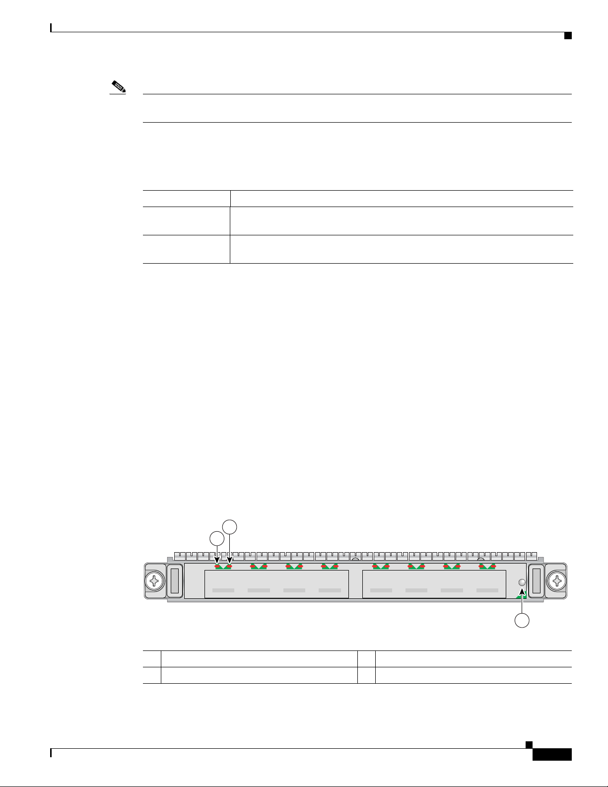
Chapter 2 Overview: Cisco XR 12000 Series Router Shared Port Adapters
STATUS
3
116852
SPA-8XCHT1/E1
C/A A/L
0
C/A
3
A/L A/L A/LC/A
2
C/A
1
C/A A/L
4
C/A
7
A/L A/L A/LC/A
6
C/A
5
1
2
Note The Cisco cable part numbers are 72-4124-01 (with Male BNC end) and 72-4131-01 (wi th Female BNC
end).
Figure 2-2 shows the Siemax connectors on the 2-Port and 4-Port Channelized T3 SPA, and Table 2-6
provides the signal descriptions for these connectors.
Table 2-6 2-Port and 4-Port Channelized T3 SPA Connectors
Connector Label Meaning
TX Transmitted signals appear on the center contact, and the outer shield is ground
for the 75-ohm RG-59 coaxial cable you attach to the TX BNC Siemax connector.
RX Received signals appear on the center contact, and the outer shield is ground for
the 75-ohm RG-59 coaxial cable you attach to the RX BNC Siemax connector.
8-Port Channelized T1/E1 SPA Overview
8-Port Channelized T1/E1 SPA Overview
The following sections describe the 8-Port Channelized T1/E1 SPA:
• 8-Port Channelized T1/E1 SPA LEDs, page 2-9
• XFP Connections, page 2-15
• 8-Port Channelized T1/E1 SPA Cables, Connectors, and Pinouts, page 2-10
8-Port Channelized T1/E1 SPA LEDs
The 8-Port Channelized T1/E1 SPA has three types of LEDs. There are two LEDs for each port on the
SPA, and one STATUS LED as shown in
Figure 2-3 8-Port Channelized T1/E1 SPA Faceplate
Figure 2-3.
OL-17438-04
1 C/A (Carrier/Alarm) LED 3 STATUS LED
2 A/L (Active Loopback) LED
The 8-Port Channelized T1/E1 SPA LEDs are described in Table 2-7.
Cisco XR 12000 Series Router SIP and SPA Hardware Installation Guide
2-9
Page 40

Chapter 2 Overview: Cisco XR 12000 Series Router Shared Port Adapters
32770
RJ-45
RJ-48c
Pin 1
Pin 8
8-Port Channelized T1/E1 SPA Overview
Table 2-7 8-Port Channelized T1/E1 SPA LEDs
LED Label Color State Meaning
C/A Off Off Port is not enabled by software.
Green On Port is enabl ed by software, and there is a valid T1 or E1
signal without any alarms.
Amber On Port is enabled by software, and there is at least one alarm.
A/L Off Off Port is not enabled by software.
Green On Port is enabl ed by software, loopback is off.
Amber On Port is enabled by software, loopback is on.
STATUS Off Off SPA power is off.
Amber On SPA power is on and good, and SPA is being configured.
Green On SPA is ready and operational.
8-Port Channelized T1/E1 SPA Interface Specifications
The E1 interface on the 8-Port Channelized T1/E1 SP A uses RJ-48c receptacles for E1 (120-Ohm) cables
with RJ-45 connectors. You can use all ports simultaneously . Each E1 connection suppor ts interfaces that
meet G.703 standards. The RJ-45 connection does not require an external transceiver. The E1 ports are
E1 interfaces that use 120-ohm shielded twisted pair (STP) cabl es.
Warning
Shielded twisted pair (STP) T1/E1 cables must be used to comply with EN55022/CISPR22 Class A
emissions requirements. For revisions 73-8358-05 through 73-8358-08 Shielded Twisted pair (STP)
T1/E1 cables must be used to comply with FCC Class A emissions requirements.
8-Port Channelized T1/E1 SPA Cables, Connectors, and Pinouts
Figure 2-4 shows an RJ-45 connector.
Note The terms RJ-45 and RJ-48c are sometimes used interchangeably. The RJ-48c is the jack or receptacle;
the RJ-45 is the connector.
Figure 2-4 RJ-45 Connector
2-10
Cisco XR 12000 Series Router SIP and SPA Hardware Installation Guide
OL-17438-04
Page 41
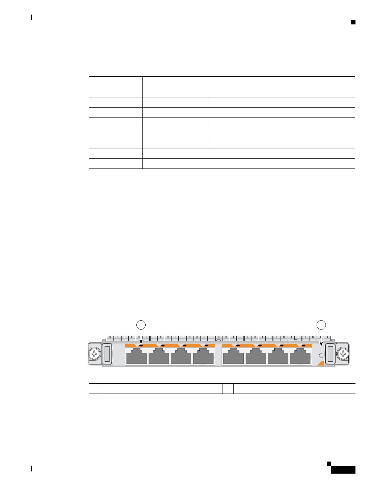
Chapter 2 Overview: Cisco XR 12000 Series Router Shared Port Adapters
STATUS
A/L
SPA-8X1FE-TX-V2
0
A/L
1
A/L
2
A/L
3
A/L
4
A/L
5
A/L
6
A/L
7
1 2
Table 2-8 describes the signals and connector pinouts for RJ-45 cable connectors.
Table 2-8 RJ-45 Connector Pinouts
Pin Signal Description
1 RX– Receive ring –
2 RX+ Receive tip +
3 NC No connection
4 TX– Transmit ring –
5 TX+ Transmit tip +
6 NC No connection
7 NC No connection
8 NC No connection
8 Port FastEthernet SPA Overview
8 Port FastEthernet SPA Overview
The following sections describe the 8-Port FastEthernet SPA:
• 8-Port FastEthernet SPA LEDs, page 2-11
• 8-Port FastEthernet SPA Ca bles, Connecto rs, and Pinouts, page 2-12
8-Port FastEthernet SPA LEDs
The 8-Port FastEthernet SPA has two types of LEDs: an A/L LED for each individual port and a STATUS
LED for the SPA, as shown in
Figure 2-5 8-Port FastEthernet SPA Faceplate
1 A/L (Active/Link) LED 2 STATUS LED
Figure 2-5.
OL-17438-04
Table 2-9 describes the 8-Port FastEthernet SPA LEDs.
Cisco XR 12000 Series Router SIP and SPA Hardware Installation Guide
2-11
Page 42

Chapter 2 Overview: Cisco XR 12000 Series Router Shared Port Adapters
242688
8 7 6 5 4 3 2 1
RJ-45 connector
8 Port FastEthernet SPA Overview
Table 2-9 8-Port FastEthernet SPA LEDs
LED Label Color State Meaning
Port Number
A/L (0, 1, 2, 3, 4,
5, 6 or 7)
1
Off Off Port is not enabled.
Green On Port is enabled and the link is up.
Amber On Port is enabled and the link is down.
STATUS Off Off SPA power is off.
Green On SPA is ready and operational.
Amber On SPA power is on and good, and the SPA is being
configured.
1. In this case, port number refers to the numbered LEDs on the 8-Port FastEthernet SPA (0, 1, 2, 3, 4, 5, 6 or 7). Each LED
number on the 8-Port FastEthernet SPA references a port on the SPA.
8-Port FastEthernet SPA Cables, Connectors, and Pinouts
The interface connectors on the 8-Port FastEthernet SPA are eight individual RJ-45 receptacles. You can
use all eight interface connectors simultaneously. Each connection supports IEEE
802.3 and Ethernet
10/100BASE-T interfaces compliant with appropriate standards. Cisco Systems does not supply
Category 5 unshielded twisted-pair
(UTP) RJ-45 cables; these cables are available commercially.
Figure 2-6 shows the RJ-45 connector.
Figure 2-6 RJ-45 Connections, Plug, and Receptacle
Table 2-10 lists the pinouts and signals for the RJ-45 connector.
Table 2-10 RJ-45 Connector Pinout
Pin Description
1 Transmit data + (TxD+)
2 TxD–
3 Receive data + (RxD+)
4 Reserved
5 Reserved
6 RxD–
7 Reserved
8 Reserved
2-12
Cisco XR 12000 Series Router SIP and SPA Hardware Installation Guide
OL-17438-04
Page 43

Chapter 2 Overview: Cisco XR 12000 Series Router Shared Port Adapters
Hub or LAN switch Ethernet port
3 TxD+
6 TxD–
1 RxD+
2 RxD–
3 RxD+
6 RxD–
1 TxD+
2 TxD–
H7101
Router
3 TxD+
6 TxD–
1 RxD+
2 RxD–
3 TxD+
6 TxD–
1 RxD+
2 RxD–
101929
Router
Note Referring to the RJ-45 pinout in Table 2-10, proper common-mode line terminations should be used for
the unused Category 5 UTP cable pairs 4/5 and 7/8. Common-mode termination reduces the
contributions to electromagnetic interference (EMI) and susceptibility to common-mode sources. Wi re
pairs 4/5 and 7/8 are actively terminated in the RJ-45 port circuitry in the 8-Port FastEthernet SPA.
The 8-Port FastEthernet SPA supports automatic MDI/MDIX crossover at all speeds of operation
allowing the SPA to work with straight-through and crossove r Ethernet cables. Depending on your RJ-45
interface cabling requirements, use the pinouts in
Figure 2-7 Straight-Through Cable Pinout, RJ-45 Connection to a Hub or Repeater
1 Port 10-Gigabit Ethernet SPA Overview
Figure 2-7 and Figure 2-8.
Figure 2-8 Crossover Cable Pinout, RJ-45 Connections Between Routers
1 Port 10-Gigabit Ethernet SPA Overview
The following sections describe the 1-Port 10-Gigabit Ethernet SPA:
• 1-Port 10-Gigabit Ethernet SPA LEDs, page 2-14
• 1-Port 10-Gigabit Ethernet SPA XFP Optical Transceiver Modules, Connectors, and Cables,
page 2-14
OL-17438-04
Cisco XR 12000 Series Router SIP and SPA Hardware Installation Guide
2-13
Page 44

1 Port 10-Gigabit Ethernet SPA Overview
STATUS
122151
ACTIVE/LINK
SPA-1X10GE-L-V2
1 2
1-Port 10-Gigabit Ethernet SPA LEDs
The 1-Port 10-Gigabit Ethernet SPA has two LEDs, an ACTIVE/LINK LED for the port and a STATUS
LED, as shown in
Figure 2-9 1-Port 10-Gigabit Ethernet SPA Faceplate
1 ACTIVE/LINK LED 2 STATUS LED
Table 2-11 describes the 1-Port 10-Gigabit Ethernet SPA LEDs.
Table 2-11 1-Port 10-Gigabit Ethernet SPA LEDs
Figure 2-9.
Chapter 2 Overview: Cisco XR 12000 Series Router Shared Port Adapters
LED Label Color State Meaning
ACTIVE/LINK Off Off Port is not enabled by software.
Green On Port is enabled by software and the link is up.
Amber On Port is enabled by software and the link is down.
STATUS Off Off SPA power is off.
Green On SPA is ready and operational.
Amber On SPA power is on and good, and the SP A is being conf igured.
1-Port 10-Gigabit Ethernet SPA XFP Optical Transceiver Modules, Connectors, and Cables
The 1-Port 10-Gigabit Ethernet SPA supports the following types of optical transceiver modules:
• Single-mode short-reach (SR) XFP module—XFP-10GLR-OC192SR
• Single-mode intermediate-reach (IR) XFP module—XFP-10GER-OC192IR
• Single-mode very-long-reach (ZR) XFP module—XFP-10GER-OC192LR
• Multi-mode short reach (SR) XFP module—XFP-10G-MM-SR
Cisco Systems qualifies the optics that are approved for use with its SPAs. As of Cisco IOS XR
Release
modules qualified for use.
3.4.1, the above-listed small form-factor pluggable (XFPs) are the only optical transceiver
2-14
Use a single-mode optical fiber that has a modal-field diameter of 8.7 ±0.5 microns (nominal diameter
is approximately 10/125 microns) to connect your router to a network.
Figure 2-10 shows the cable type for use with the XFP optical transceiver module on the 1-Port
10-Gigabit Ethernet SPA.
Cisco XR 12000 Series Router SIP and SPA Hardware Installation Guide
OL-17438-04
Page 45

Chapter 2 Overview: Cisco XR 12000 Series Router Shared Port Adapters
/ / / /
/ /
TXRX
84929
129499
Figure 2-10 LC-Type Cable for the XFP Optical Transceiver Modules
Note The 40-pin connector on the 1-Port 10-Gigabit Ethernet SPA is used for resilient packet ring (RPR)
connections. This feature is not supported in Cisco IOS XR Release 4.3.0.
XFP Connections
The 10GLR, 10GER, and 10GZR XFP modules include an optical transmitter and receiver pair
integrated with Clock and Data Recovery
high-speed serial links at the rate of 10.3125 Gbps (10 Gigabit Ethernet) on single-mode fiber (SMF).
The transmit side recovers and retimes the 10-Gbps serial data and passes it to a laser driver. The laser
driver biases and modulates a 1310-nm, 850 nm or 155-nm laser, enabling data transmission over SMF
through an LC connector. The receive side recovers and retimes the 10-Gbps optical data stream from a
photo detector transimpedance amplifier and passes it to an output driver.
See the label on the XFP module for technology type and model. Figure 2-11 shows an XFP module and
Table 2-12 shows the XFP module specifications.
1 Port 10-Gigabit Ethernet SPA Overview
(CDR) integrated circuits. The XFP modules provide
Figure 2-11 XFP Module
XFP module dimensions are:
• Height: 12.5 mm
• Width: 18.35 mm
• Length: 71.1mm
OL-17438-04
Cisco XR 12000 Series Router SIP and SPA Hardware Installation Guide
2-15
Page 46

1 Port 10-Gigabit Ethernet SPA Overview
Table 2-12 XFP Module Specifications for 10-Gigabit Ethernet SPA
Specification Description
Wavele ngth (T X) 1 0 G L R S R - 1 : 1260 nm to 1355 nm
Cabling distance (maximum) 10GLR SR-1: 6.2 miles (10 km)
Operating case temperature range 10GLR SR-1: 23 to 158 degrees F (–5 to 70 degrees C)
Storage temperature range 10GLR SR-1: –40 to 185 degrees F (–40 to 85 degrees C)
TX power 10GLR SR-1: –8.2 to 0.5 dBm
Receiver sensitivity (maximum) 1 0 G L R S R - 1 : – 12.6 dBm
RX over lo a d 10GL R SR-1 : 0.5 dBm
Maximum receiver power damage 10GLR SR-1: +5 dBm
Chapter 2 Overview: Cisco XR 12000 Series Router Shared Port Adapters
10GER IR-2: 1530 nm to 1565 nm
10GZR LR-2: 1530 nm to 1565 nm
10G-MM-SR: 840 nm to 860 nm
10GER IR-2: 24.8 miles (40 km)
10GZR LR-2: 50 miles (80 km)
10G-MM-SR: 26m, 33m, 66m, 82m, 300m
10GER IR-2: 23 to 158 degrees F (–5 to 70 degrees C)
10GZR LR-2: 23 to 158 degrees F (–5 to 70 degrees C)
10G-MM-SR: 32 to 158 degrees F (0 to 70 degrees C)
10GER IR-2: –40 to 185 degrees F (–40 to 85 degrees C)
10GZR LR-2: –40 to 185 degrees F (–40 to 85 degrees C)
10G-MM-SR: –40 to 185 degrees F (–40 to 85 degrees C)
10GER IR-2: –4.7 to 4 dBm
10GZR LR-2: 0 to 4 dBm
10G-MM-SR: 3dBm,-1.5dBm,-1dBm
10GE R IR-2 : – 14.1 dBm
10GZR LR-2: –24 dBm
10G-MM-SR: -11.1dBm
10GER IR-2: –1.0 dBm
10GZR LR-2: –7.0 dBm
10G-MM-SR: 1.0 dBm
10GER IR-2: +5 dBm
10GZR LR-2: +5 dBm
10G-MM-SR: -1dBm
XFP Port Cabling Specifications
Table 2-13 shows the port cabling specifications for an XFP module.
Table 2-13 XFP Port Cabling Specifications
XFP Module Wavelength Fiber Type
XFP-10GLR-OC192SR 1310 nm SMF
XFP-10GER-OC192IR 1550 nm SMF
XFP-10GZR-OC192LR 1550 nm SMF
XFP-10G-MM-SR 850 nm MMF
Cisco XR 12000 Series Router SIP and SPA Hardware Installation Guide
2-16
OL-17438-04
Page 47

Chapter 2 Overview: Cisco XR 12000 Series Router Shared Port Adapters
STATUS
0
1
A/L
A/L
SPA-2X1GE
0
1
A/L
A/L
138041
2
1 3
2-Port Gigabit Ethernet SPA Overview
The following sections describe the version 1 and version 2 of the 2-Port Gigabit Ethernet SPA:
• 2-Port Gigabit Ethernet SPA LEDs, page 2-17
• 2-Port Gigabit Ethernet SPA (Version 2) LEDs, page 2-18
• SFP Module Cabling and Connection Equipment, page 2-21
2-Port Gigabit Ethernet SPA LEDs
The 2-Port Gigabit Ethernet SPA has two types of LEDs: an A/L LED for each port and a ST ATUS LED,
as shown in
Figure 2-12 2-Port Gigabit Ethernet SPA Faceplate
Figure 2-12.
2-Port Gigabit Ethernet SPA Overview
OL-17438-04
1 A/L (Active/Link) LED 2 STATUS LED
Table 2-14 describes the 2-Port Gigabit Ethernet SPA LEDs.
Table 2-14 2-Port Gigabit Ethernet SPA LEDs
LED Label Color State Meaning
A/L Off Off Port is not enabled.
Green On Port is enabled and the link is up.
Amber On Port is enabled and the link is down.
STATUS Off Off SPA power is off.
Green On SPA is ready and operational.
Amber On SPA power is on and good, and SPA is being configured.
Cisco XR 12000 Series Router SIP and SPA Hardware Installation Guide
2-17
Page 48
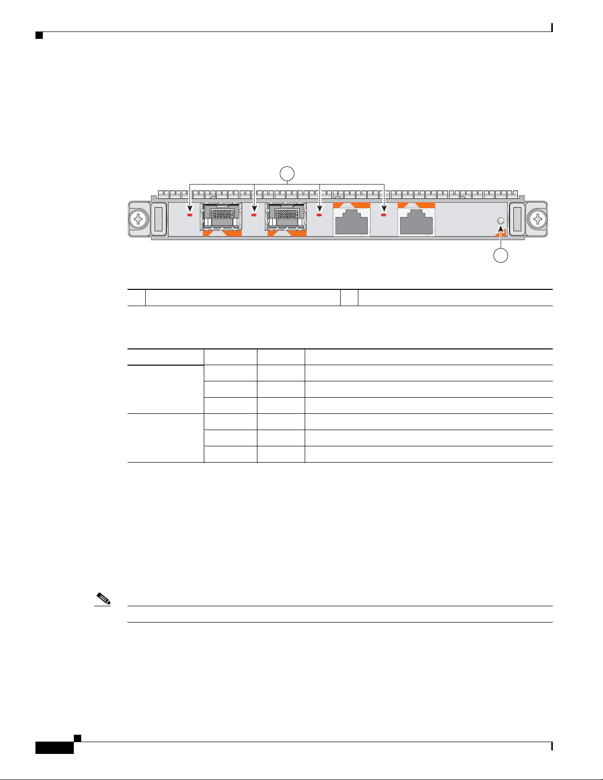
Chapter 2 Overview: Cisco XR 12000 Series Router Shared Port Adapters
2-Port Gigabit Ethernet SPA Overview
2-Port Gigabit Ethernet SPA (Version 2) LEDs
The 2-Port Gigabit Ethernet SPA (Version 2) has two types of LEDs: an A/L LED for each port (SFP and
RJ45) and a STATUS LED, as shown in
Figure 2-13 2-Port Gigabit Ethernet SPA (Version 2) Faceplate
Figure 2-13.
1
1
STATUS
SPA-2X1GE-V2
A/L
0
A/L
0
1
A/L
A/L
2
Table 2-15 describes the 2-Port Gigabit Ethernet SPA (Version 2) LEDs.
1 A/L (Active/Link) LED 2 STATUS LED
Table 2-15 2-Port Gigabit Ethernet SPA (Version 2) LEDs
LED Label Color State Meaning
A/L Off Off Port is not enabled.
Green On Port is enabled by software and the link is up.
Amber On Port is enabled by software and the link is down.
STATUS Off Off SPA power is off.
Green On SPA is ready and operational.
Amber On SPA power is on and good, and SPA is being configured.
The valid configuration of the SFP and RJ45 ports for the 2-Port Gigabit Ethernet SPA (Version 2) are
as follows:
• Port 0 (SFP) and Port 1 (SFP)
• Port 0 (SFP) and Port 1 (RJ45)
211969
2-18
• Port 0 (RJ45) and Port 1 (SFP)
• Port 0 (RJ45) and Port 1 (RJ45)
or any single port
Note For Cisco XR 12000 Series Router, the RJ45 port is not supported on 2-Port Gigabit Ethernet SPA.
Cisco XR 12000 Series Router SIP and SPA Hardware Installation Guide
OL-17438-04
Page 49

Chapter 2 Overview: Cisco XR 12000 Series Router Shared Port Adapters
242688
8 7 6 5 4 3 2 1
RJ-45 connector
2-Port Fast Ethernet SPA Cables, Connectors, and Pinouts
The interface connectors on the 2-Port Fast Ethernet SPA are two individual RJ-45 receptacles. You can
use both the interface connectors simultaneously. Each connection supports IEEE 802.3 and Ethernet
10/100BASE-T interfaces compliant with appropriate standards. Cisco Systems does not supply
Category 5 unshielded twisted pair (UTP) RJ-45 cables. these c ables are available commercially. The
RJ-45 connectors are shown in
Figure 2-14 2-Port Fast Ether n et RJ-45 Connections, Plug, and Receptacle
Table 2-16 lists the pinouts and signals for the RJ-45 connector.
Figure 2-14.
2-Port Gigabit Ethernet SPA Overview
Table 2-16 2-Port Fast Ethernet RJ-45 Connector Pinouts
Pin Description
1 Transmit data + (TxD+)
2 TxD–
3 Receive data + (RxD+)
4 Reserved
5 Reserved
6 RxD–
7 Reserved
8 Reserved
2-Port Gigabit Ethernet SPA Cables and Connectors
The interface connectors on the 2-Port Gigabi t Ethernet SPA are two indi vidual f iber-opt ic receiv ers that
support SFP modules. Each port can send and receive traffic using the optical fiber connections.
SFP Module Connections
The small form-factor pluggable (SFP) module is an input/output (I/O) de vice that plugs into the Gigabit
Ethernet ports on the 2-Port Gigabit Ethernet SPA, linking the port with a fiber-optic network.
OL-17438-04
Note The 2-Port Gigabit Ethernet SPA will only accept the SFP modules listed as supported in this document.
An SFP module check is run every time an SFP module is inserted int o the 2-Port Gigabit Ethernet SPA
and only SFP modules that pass this check will be usable by the 2-Port Gigabit Ethernet SPA.
Cisco XR 12000 Series Router SIP and SPA Hardware Installation Guide
2-19
Page 50

2-Port Gigabit Ethernet SPA Overview
SFP modules exist for technologies other than Gigabit Ethernet and for products other than the 2-Port
Gigabit Ethernet SP A. Ho wev er, the information in this document pertains only to SFP modules that plug
into the 2-Port Gigabit Ethernet SPA ports.
The SFP module has a receiver port (RX) and a transmitter port (TX) that compose one optical interface.
Table 2-17 and Table 2-18 provide SFP module information and specifications.
Table 2-17 SFP Module Options
SFP Module
Product Number
SFP-GE-S Short wavelength
SFP-GE-L Long wavelength/long haul
SFP-GE-Z Exten ded wavelength
SFP-GE-T RJ-45 copper SFP module
Chapter 2 Overview: Cisco XR 12000 Series Router Shared Port Adapters
SFP Module Description
Contains a Class 1 laser of 850 nm for
(1000BASE-SX)
(1000BASE-LX/LH)
(1000BASE-ZX)
(1000BASE-T)
1000BASE-SX (short wavelength) applications.
Contains a Class 1 laser of 1310 nm for
1000BASE-LX/LH (long wavelength)
applications.
Contains a Class 1 laser of 1550 nm for
1000BASE-ZX (extended wavelength)
applications.
Provides full-duplex Gigabit Ethernet
connectivity to high-end workstations and
between wiring closets over an existing copper
network infrastructure.
Table 2-18 SFP Module Specifications
Specification Description
Wavelength SFP-GE-S: 770 to 860 nm
SFP-GE-L: 1270 to 1355 nm
SFP-GE-Z: 1500 to 1580 nm
SFP-GE-T: N/A.
Cabling distance (maximum) SFP-GE-S: 500 m on 50/125um MMF; 300 m on 62.5/125um MMF
SFP-GE-L: 6.2 miles (10 km)
SFP-GE-Z: 49.7 miles (80 km)
SFP-GE-T: 328 ft. (100 m)
Operating case temperature
range
SFP-GE-S: 23 to 185 degrees F (–5 to 85 degrees C)
SFP-GE-L: 23 to 185 degrees F (–5 to 85 degrees C)
SFP-GE-Z: 23 to 185 degrees F (–5 to 85 degrees C)
Storage temperature range SFP-GE-S: –40 to 185 degrees F (–40 to 85 degrees C)
SFP-GE-L: –40 to 185 degrees F (–40 to 85 degrees C)
SFP-GE-Z: –40 to 185 degrees F (–40 to 85 degrees C)
Supply voltage range SFP-GE-S: 3.1 to 3.5 V
SFP-GE-L: 3.1 to 3.5 V
SFP-GE-Z: 3.1 to 3.5 V
2-20
Cisco XR 12000 Series Router SIP and SPA Hardware Installation Guide
OL-17438-04
Page 51

Chapter 2 Overview: Cisco XR 12000 Series Router Shared Port Adapters
SFP-GE-S Modules
The 1000BASE-SX (short wa velength) mo dule operates on standard multimod e fiber -optic link spans of
up to 500 m on 50/125um MMF and 300 m on 62.5/125um MMF.
SFP-GE-L Modules
The 1000BASE-LX/LH (long wavelength/long haul) module interfaces fully comply with the
IEEE 802.3z 1000BASE-LX standard. However, their higher optical quality allows them to reach
6.2
miles (10 km) over single-mode fiber (SMF) versus the 3.1 miles (5 km) specified in the standard.
SFP-GE-Z Modules
The 1000BASE-ZX (extended wavelength) module operates on ordinary single-mode fiber-optic link
spans of up to 49.7 miles
single-mode fiber or dispersion-shifted single-mode fiber (premium single-mode fiber has a lower
attenuation per unit length than ordinary single-mode fiber; dispersion-shifted single-mode fiber has
both lower attenuation and less dispersion).
The 1000BASE-ZX module mu st be coupled to sing le-mode f iber-optic cable, which is the type of cable
typically used in long-haul telecommunications applications. The 1000BASE-ZX module will not
operate correctly when coupled to multimode fiber, and it is not intended to be used in environments
where multimode fiber is frequently used (for example, building backbones, or horizontal cabling).
The 1000BASE-ZX module is intended to be used as a Physical Medium Dependent (PMD) component
for Gigabit Ethernet interfaces found on various switch and router products. It operates at a signaling
rate of 1250 Mbaud, transmitting and receiving 8B/10B encoded data.
(80 km). Link spans of up to 62.1 miles (100 km) are possible using premium
2-Port Gigabit Ethernet SPA Overview
When shorter lengths of single-mode fiber are used, it may be necessary to insert an in-line optical
attenuator in the link to avoid overloading the receiver.
• Insert a 10-dB in-line optical attenuator between the fiber-optic cable plant and the receiving port
on the 1000BASE-ZX module at each end of the link whenever the fiber-opti c cable span is less than
15.5 miles (25 km).
• Insert a 5-dB in-line optical attenuator between the fiber-optic cable plant and the receiving port on
the 1000BASE-ZX module at each end of the link whenever the f ibe r -optic cable span is eq ual to or
greater than 15.5 miles (25 km) but less than 31 miles (50 km).
SFP-GE-T Modules
The SFP-GE-T (1000BASE-T copper SFP module) provides full-duplex Gigabit Ethernet connectivity
to high-end workstations and between wiring cl osets over an e xisting copper netw ork infrastructure. The
SFP-GE-T maximum cabling distance is 328 feet (100 m).
SFP Module Cabling and Connection Equipment
Table 2-19 provides cabling specifications for the SFP modules that can be installed on the 2-Port
Gigabit Ethernet SPA. Note that all SFP ports have LC-type connectors.
The minimum cable distance for the SFP-GE-S is 6.5 feet (2 m), and the minimum link distance for the
SFP-GE-Z is 6.2 miles (10 km) with an 8-dB attenuator installed at each end of the link. Without
attenuators, the minimum link distance for the SFP-GE-Z is 24.9 miles (40
km).
OL-17438-04
Cisco XR 12000 Series Router SIP and SPA Hardware Installation Guide
2-21
Page 52

5-Port Gigabit Ethernet SPA Overview
Table 2-19 SFP Module Port Cabling Specifications
SFP Modules
SFP-GE-S 850 MMF
SFP-GE-L 1300 MMF2 and
SFP-GE-Z 1550 SMF 9/10 — 49.7 miles
SFP-GE-T N/A Copper N/A N/A 328 ft. (100 m)
1. Multimode fiber (MMF) only.
2. A mode-conditioning patch cord is required.
When using the SFP-GE-L with 62.5-micron diameter MMF, you must install a mode-conditioning patch cord between the
SFP module and the MMF cable on both the transmit and the receive ends of the link when link distances are greater than
ft (300 m).
984
We do not recommend using the SFP-GE-L and MMF with no patch cord for very short link distance (tens of meters). The
result could be an elevated bit error rate (BER).
3. Dispersion-shifted single-mode fiber-optic cable.
Wavelength
(nm)
Fiber Type
1
SMF
3
SMF
Chapter 2 Overview: Cisco XR 12000 Series Router Shared Port Adapters
Modal
Core Size
(micron)
Bandwidth
(MHz/km)
Maximum
Cable Distance
62.5 160 722 ft (220 m)
62.5 200 984 ft (300 m)
50.0 400 1640 ft (500 m)
50.0 500 1804 ft (550 m)
62.5 500 1804 ft (550 m)
50.0 400 1804 ft (550 m)
50.0 500 1804 ft (550 m)
9/10 — 6.2 miles (10 km)
(80
km)
8 — 62.1 miles
(100
km)
Note The 1000BASE-ZX SFP modules provide an optical po wer budget of 21.5 dB. You should measure your
cable plant with an optical loss test set to verify that the optical loss of the cable plant (including
connectors and splices) is less than or equal to 21.5 dB. The optical loss measurement must be performed
with a 1550-nm light source.
5-Port Gigabit Ethernet SPA Overview
The following sections describe the 5-Port Gigabit Ethernet SPA:
• 5-Port Gigabit Ethernet SPA LEDs, page 2-23
• 5-Port Gigabit Ethernet SPA Cables and Connectors, page 2-23
Cisco XR 12000 Series Router SIP and SPA Hardware Installation Guide
2-22
OL-17438-04
Page 53

Chapter 2 Overview: Cisco XR 12000 Series Router Shared Port Adapters
A/L
A/L
A/L
A/L
A/L
STATUS
SPA-5X1GE-V2
1 2
5-Port Gigabit Ethernet SPA LEDs
The 5-Port Gigabit Ethernet SPA has two types of LEDs: an A/L LED for each individual port and a
STATUS LED for the SPA, as shown in
Figure 2-15 5-Port Gigabit Ethernet SPA Faceplate
1 A/L (Active/Link) LED 2 STATUS LED
Table 2-20 describes the 5-Port Gigabit Ethernet SPA LEDs.
5-Port Gigabit Ethernet SPA Overview
Figure 2-15.
Table 2-20 5-Port Gigabit Ethernet SPA LEDs
LED Label Color State Meaning
A/L Off Off Port is not enabled.
Green On Port is enabled and the link is up.
Amber On Port is enabled and the link is down.
STATUS Off Off SPA power is off.
Green On SPA is ready and operational.
Amber On SPA power is on and good, and the SP A is being conf igured.
5-Port Gigabit Ethernet SPA Cables and Connectors
The 5-Port Gigabit Ethernet SPA has five electrical connectors that support SFP modules. Each port can
send and receive traffic using cabling appropriate for the SFP module inserted.
SFP Module Connections
The small form-factor pluggable (SFP) module is an input/output (I/O) de vice that plugs into the Gigabit
Ethernet ports on the 5-Port Gigabit Ethernet SPA, linking the port with a fiber-optic network.
Note The 5-Port Gigabit Ethernet SPA accepts only the SFP modules listed as supported in this document. An
SFP module check is run every time an SFP module is inserted into the 5-Port Gigabit Ethernet SPA, and
only SFP modules that pass this check can be used by the 5-Port Gigabit Ethernet SPA.
SFP modules exist for technologies other than Gigabit Ethernet and for products other than the 5-Port
Gigabit Ethernet SP A. Ho wev er, the information in this document pertains only to SFP modules that plug
into the 5-Port Gigabit Ethernet SPA ports.
Cisco XR 12000 Series Router SIP and SPA Hardware Installation Guide
OL-17438-04
2-23
Page 54

5-Port Gigabit Ethernet SPA Overview
The SFP module has a receiver port (RX) and a transmitter port (TX) that compose one optical interface.
Table 2-21 and Table 2-22 provide SFP module information and specifications.
Table 2-21 SFP Module Options
SFP Module
Product Number
SFP-GE-S Short wavelength
SFP-GE-L Long wavelength/long haul
SFP-GE-Z Exten ded wavelength
SFP-GE-T RJ-45 copper SFP module
Chapter 2 Overview: Cisco XR 12000 Series Router Shared Port Adapters
SFP Module Description
Contains a Class 1 laser of 850 nm for
(1000BASE-SX)
(1000BASE-LX/LH)
(1000BASE-ZX)
(1000BASE-T)
1000BASE-SX (short-wavelength) applications.
Contains a Class 1 laser of 1310 nm for
1000BASE-LX/LH (long-wavelength)
applications.
Contains a Class 1 laser of 1550 nm for
1000BASE-ZX (extended-wavelength)
applications.
Provides full-duplex Gigabit Ethernet
connectivity to high-end workstations and
between wiring closets over an existing copper
network infrastructure.
SFP-GE-S Modules
Table 2-22 SFP Module Specifications
Specification Description
Wavelength SFP-GE-S: 770 to 860 nm
SFP-GE-L: 1270 to 1355 nm
SFP-GE-Z: 1500 to 1580 nm
SFP-GE-T: N/A
Cabling distance (maximum) SFP-GE-S: 500 m on 50/125um MMF; 300 m on 62.5/125um MMF
SFP-GE-L: 6.2 miles (10 km)
SFP-GE-Z: 49.7 miles (80 km)
SFP-GE-T: 328 ft. (100 m)
Operating case temperature
range
SFP-GE-S: 23 to 185 degrees F (–5 to 85 degrees C)
SFP-GE-L: 23 to 185 degrees F (–5 to 85 degrees C)
SFP-GE-Z: 23 to 185 degrees F (–5 to 85 degrees C)
Storage temperature range SFP-GE-S: –40 to 185 degrees F (–40 to 85 degrees C)
SFP-GE-L: –40 to 185 degrees F (–40 to 85 degrees C)
SFP-GE-Z: –40 to 185 degrees F (–40 to 85 degrees C)
Supply voltage range SFP-GE-S: 3.1 to 3.5 V
SFP-GE-L: 3.1 to 3.5 V
SFP-GE-Z: 3.1 to 3.5 V
2-24
The 1000BASE-SX (short-wavelength) module operates on standard multimode fiber-optic link spans
of up to 500 m on 50/125um multimode fiber (MMF) and 300 m on 62.5/125um MMF.
Cisco XR 12000 Series Router SIP and SPA Hardware Installation Guide
OL-17438-04
Page 55

Chapter 2 Overview: Cisco XR 12000 Series Router Shared Port Adapters
SFP-GE-L Modules
The 1000BASE-LX/LH (long-wavelength/long-haul) module interfaces fully comply with the
IEEE 802.3z 1000BASE-LX standard. However, their higher optical quality allows them to reach
6.2
miles (10 km) over single-mode fiber (SMF) versus the 3.1 miles (5 km) specified in the standard.
SFP-GE-Z Modules
The 1000BASE-ZX (extended wavelength) module operates on ordinary single-mode fiber-optic link
spans of up to 49.7 miles
(80 km). Link spans of up to 62.1 miles (100 km) are possible using premium
single-mode fiber or dispersion-shifted single-mode fiber. (Premium single-mode fiber has a lower
attenuation per unit length than ordinary single-mode fiber; dispersion-shifted single-mode fiber has
both lower attenuation and less dispersion.)
The 1000BASE-ZX module mu st be coupled to sing le-mode f iber-optic cable, which is the type of cable
typically used in long-haul telecommunications applications. The 1000BASE-ZX module does not
operate correctly when coupled to multimode fiber, and it is not intended to be used in environments in
which multimode fiber is frequently used (for example, building backbones or horizontal cabling).
The 1000BASE-ZX module is intended to be used as a Physical Medium Dependent (PMD) component
for Gigabit Ethernet interfaces found on various switch and router products. It operates at a signaling
rate of 1250 Mbaud, transmitting and receiving 8B/10B encoded data.
When shorter lengths of single-mode fiber are used, it may be necessary to insert an inline optical
attenuator in the link to avoid overloading the receiver. Use the following guidelines:
• Insert a 10-dB inline optical attenuator between the f iber -optic cable plant and th e recei ving por t on
the 1000BASE-ZX module at each end of the link whenever the fiber- optic cable span is less than
15.5 miles (25 km).
5-Port Gigabit Ethernet SPA Overview
• Insert a 5-dB inline optical attenuator between the fiber-optic cable plant and the receiving port on
the 1000BASE-ZX module at each end of the link whenever the f ibe r -optic cable span is eq ual to or
greater than 15.5 miles (25 km) but less than 31 miles (50 km).
SFP-GE-T Modules
The SFP-GE-T (1000BASE-T copper SFP module) provides full-duplex Gigabit Ethernet connectivity
to high-end workstations and between wiring cl osets over an e xisting copper netw ork infrastructure. The
SFP-GE-T maximum cabling distance is 328 feet (100 m).
SFP Module Cabling and Connection Equipment
Table 2-23 provides cabling specifications for the SFP modules that can be installed on the 5-Port
Gigabit Ethernet SPA. Note that all SFP ports have LC-type connectors.
The minimum cable distance for the SFP-GE-S is 6.5 feet (2 m), and the minimum link distance for the
SFP-GE-Z is 6.2 miles (10 km) with an 8-dB attenuator installed at each end of the link. Without
attenuators, the minimum link distance for the SFP-GE-Z is 24.9 miles (40
km).
OL-17438-04
Cisco XR 12000 Series Router SIP and SPA Hardware Installation Guide
2-25
Page 56

10-Port Gigabit Ethernet SPA Overview
Table 2-23 SFP Module Port Cabling Specifications
SFP Modules
SFP-GE-S 850 MMF
SFP-GE-L 1300 MMF2 and
SFP-GE-Z 1550 SMF 9/10 — 49.7 miles
SFP-GE-T N/A Copper N/A N/A 328 ft. (100 m)
1. Multimode fiber (MMF) only.
2. A mode-conditioning patch cord is required.
When using the SFP-GE-L with 62.5-micron diameter MMF, you must install a mode-conditioning patch cord between the
SFP module and the MMF cable on both the transmit and the receive ends of the link when link distances are greater than
ft (300 m).
984
We do not recommend using the SFP-GE-L and MMF with no patch cord for very short link distance (tens of meters). The
result could be an elevated bit error rate (BER).
3. Dispersion-shifted single-mode fiber-optic cable.
Wavelength
(nm)
Fiber Type
1
SMF
3
SMF
Chapter 2 Overview: Cisco XR 12000 Series Router Shared Port Adapters
Modal
Core Size
(micron)
Bandwidth
(MHz/km)
Maximum
Cable Distance
62.5 160 722 ft (220 m)
62.5 200 984 ft (300 m)
50.0 400 1640 ft (500 m)
50.0 500 1804 ft (550 m)
62.5 500 1804 ft (550 m)
50.0 400 1804 ft (550 m)
50.0 500 1804 ft (550 m)
9/10 — 6.2 miles (10 km)
(80
km)
8 — 62.1 miles
(100
km)
Note The 1000BASE-ZX SFP modules provide an optical po wer budget of 21.5 dB. You should measure your
cable plant with an optical loss test set to verify that the optical loss of the cable plant (including
connectors and splices) is less than or equal to 21.5 dB. The optical loss measurement must be performed
with a 1550-nm light source.
10-Port Gigabit Ethernet SPA Overview
The following sections describe the 10-Port Gigabit Ethernet SPA:
• 10-Port Gigabit Ethernet SPA LEDs, page 2-27
• 10-Port Gigabit Ethernet SPA Cables and Connectors, page 2-27
Cisco XR 12000 Series Router SIP and SPA Hardware Installation Guide
2-26
OL-17438-04
Page 57

Chapter 2 Overview: Cisco XR 12000 Series Router Shared Port Adapters
1 2
10-Port Gigabit Ethernet SPA LEDs
The 10-Port Gigabit Ethernet SPA has two types of LEDs: an A/L LED for each individual port and a
STATUS LED for the SPA, as shown in
Figure 2-16 10-Port Gigabit Ethernet SPA Faceplate
10-Port Gigabit Ethernet SPA Overview
Figure 2-16.
1 A/L (Active/Link) LED 2 STATUS LED
Table 2-24 describes the 10-Port Gigabit Ethernet SPA LEDs.
Table 2-24 10-Port Gigabit Ethernet SPA LEDs
LED Label Color State Meaning
A/L Off Off Port is not enabled.
Green On Port is enabled and the link is up.
Amber On Port is enabled and the link is down.
STATUS Off Off SPA power is off.
Green On SPA is ready and operational.
Amber On SPA power is on and good, and the SPA is being
configured.
10-Port Gigabit Ethernet SPA Cables and Connectors
The 10-Port Gigabit Ethernet SPA has ten electrical connectors that support SFP modules. Each port can
send and receive traffic using cabling appropriate for the SFP module inserted.
SFP Module Connections
The small form-factor pluggable (SFP) module is an input/output (I/O) de vice that plugs into the Gigabit
Ethernet optical slots on the 10-Port Gigabit Ethernet SPA, linking the port with a 1000BASE-X
fiber-optic network.
Cisco XR 12000 Series Router SIP and SPA Hardware Installation Guide
OL-17438-04
2-27
Page 58

10-Port Gigabit Ethernet SPA Overview
Note The 10-Port Gigabit Ethernet SPA accepts only the SFP modules listed as supported in this document.
An SFP module check is run every time an SFP is inserted into the 10-Port Gigabit Ethernet SPA, and
only SFP modules that pass this check can be used by the 10-Port Gigabit Ethernet SPA.
SFP modules exist for technologies other than Gigabit Ethernet and for products other than the 10-Port
Gigabit Ethernet SP A. Ho wev er, the information in this document pertains only to SFP modules that plug
into the 10-Port Gigabit Ethernet SPA ports.
The SFP module has a receiver port (RX) and a transmitter port (TX) that compose one optical interface.
Table 2-25 and Table 2-26 provide SFP information and specifications.
Table 2-25 10-Port Gigabit Ethernet SFP Module Options
SFP Module
Product Number
SFP-GE-S Short wavelength
SFP-GE-L Long wavelength/long haul
SFP-GE-Z Exten ded wavelength
Chapter 2 Overview: Cisco XR 12000 Series Router Shared Port Adapters
SFP Module Description
Contains a Class 1 laser of 850 nm for
(1000BASE-SX)
(1000BASE-LX/LH)
(1000BASE-ZX)
1000BASE-SX (short-wavelength) applications.
Contains a Class 1 laser of 1310 nm for
1000BASE-LX/LH (long-wavelength)
applications.
Contains a Class 1 laser of 1550 nm for
1000BASE-ZX (extended-wavelength)
applications.
SFP-GE-S Modules
Table 2-26 10-Port Gigabit Ethernet SFP Module Specifications
Specification Description
Wavelength SFP-GE-S: 770 to 860 nm
SFP-GE-L: 1270 to 1355 nm
SFP-GE-Z: 1500 to 1580 nm
Cabling distance (maximum) SFP-GE-S: 500 m on 50/125um MMF; 300 m on 62.5/125um MMF
SFP-GE-L: 6.2 miles (10 km)
SFP-GE-Z: 49.7 miles (80 km)
Operating case temperature
range
SFP-GE-S: 23 to 185 degrees F (–5 to 85 degrees C)
SFP-GE-L: 23 to 185 degrees F (–5 to 85 degrees C)
SFP-GE-Z: 23 to 185 degrees F (–5 to 85 degrees C)
Storage temperature range SFP-GE-S: –40 to 185 degrees F (–40 to 85 degrees C)
SFP-GE-L: –40 to 185 degrees F (–40 to 85 degrees C)
SFP-GE-Z: –40 to 185 degrees F (–40 to 85 degrees C)
Supply voltage range SFP-GE-S: 3.1 to 3.5 V
SFP-GE-L: 3.1 to 3.5 V
SFP-GE-Z: 3.1 to 3.5 V
The 1000BASE-SX (short-wavelength) module operates on standard multimode fiber-optic link spans
of up to 500 m on 50/125um multimode fiber (MMF) and 300 m on 62.5/125um MMF.
2-28
Cisco XR 12000 Series Router SIP and SPA Hardware Installation Guide
OL-17438-04
Page 59

Chapter 2 Overview: Cisco XR 12000 Series Router Shared Port Adapters
SFP-GE-L Modules
The 1000BASE-LX/LH (long-wavelength/long-haul) module interfaces fully comply with the
IEEE 802.3z 1000BASE-LX standard. However, their higher optical quality allows them to reach
6.2
miles (10 km) over single-mode fiber (SMF) versus the 3.1 miles (5 km) specified in the standard.
SFP-GE-Z Modules
The 1000BASE-ZX (extended-wavelength) module operates on ordinary single-mode fiber-optic link
spans of up to 49.7 miles
(80 km). Link spans of up to 62.1 miles (100 km) are possible using premium
single-mode fiber or dispersion-shifted single-mode fiber. (Premium single-mode fiber has a lower
attenuation per unit length than ordinary single-mode fiber; dispersion-shifted single-mode fiber has
both lower attenuation and less dispersion.)
The 1000BASE-ZX module mu st be coupled to sing le-mode f iber-optic cable, which is the type of cable
typically used in long-haul telecommunications applications. The 1000BASE-ZX module does not
operate correctly when coupled to multimode fiber, and it is not intended to be used in environments in
which multimode fiber is frequently used (for example, building backbones or horizontal cabling).
The 1000BASE-ZX module is intended to be used as a Physical Medium Dependent (PMD) component
for Gigabit Ethernet interfaces found on various switch and router products. It operates at a signaling
rate of 1250 Mbaud, transmitting and receiving 8B/10B encoded data.
When shorter lengths of single-mode fiber are used, it may be necessary to insert an inline optical
attenuator in the link to avoid overloading the receiver. Use the following guidelines:
• Insert a 10-dB inline optical attenuator between the f iber -optic cable plant and th e recei ving por t on
the 1000BASE-ZX module at each end of the link whenever the fiber- optic cable span is less than
15.5 miles (25 km).
10-Port Gigabit Ethernet SPA Overview
• Insert a 5-dB inline optical attenuator between the fiber-optic cable plant and the receiving port on
the 1000BASE-ZX module at each end of the link whenever the f ibe r -optic cable span is eq ual to or
greater than 15.5 miles (25 km) but less than 31 miles (50 km).
SFP Module Cabling and Connection Equipment
Table 2-27 provides cabling specifications for the SFP modules that can be installed on the 10-Port
Gigabit Ethernet SPA. Note that all SFP ports have LC-type connectors.
The minimum cable distance for the SFP-GE-S is 6.5 feet (2 m), and the minimum link distance for the
SFP-GE-Z is 6.2 miles (10 km) with an 8-dB attenuator installed at each end of the link. Without
attenuators, the minimum link distance for the SFP-GE-Z is 24.9 miles (40
Table 2-27 SFP Module Port Cabling Specifications
Wavelength
SFP Modules
SFP-GE-S 850 MMF
SFP-GE-L 1300 SMF 9/10 — 6.2 miles (10 km)
(nm)
Fiber Type
km).
Modal
Core Size
(micron)
1
62.5 160 722 ft (220 m)
Bandwidth
(MHz/km)
Maximum
Cable Distance
62.5 200 984 ft (300 m)
50.0 400 1640 ft (500 m)
50.0 500 1804 ft (550 m)
OL-17438-04
Cisco XR 12000 Series Router SIP and SPA Hardware Installation Guide
2-29
Page 60

1-Port Channelized STM-1/OC-3 SPA Overview
SPA-1XCHSTM1/OC3
STATUS
138847
0
C/A
A/L
1
2
3
Table 2-27 SFP Module Port Cabling Specifications (continued)
SFP Modules
SFP-GE-Z 1550 SMF 9/10 — 49.7 miles
1. Multimode fiber (MMF) only.
2. Dispersion-shifted single-mode fiber-optic cable.
Note The 1000BASE-ZX SFP modules provide an optical po wer budget of 21.5 dB. You should measure your
cable plant with an optical loss test set to verify that the optical loss of the cable plant (including
connectors and splices) is less than or equal to 21.5 dB. The optical loss measurement must be performed
with a 1550-nm light source.
Wavelength
(nm) Fiber Type
2
SMF
Chapter 2 Overview: Cisco XR 12000 Series Router Shared Port Adapters
Modal
Core Size
(micron)
Bandwidth
(MHz/km)
Maximum
Cable Distance
(80
km)
8 — 62.1 miles
(100
km)
1-Port Channelized STM-1/OC-3 SPA Overview
The following sections describe the 1-Port Channelized STM-1/OC-3 SPA:
• 1-Port Channelized STM-1/OC-3 SPA LEDs, page 2-30
• 1-Port Channelized STM-1/OC-3 SPA Interface Specifications, page 2-31
• 1-Port Channelized STM-1/OC-3 SPA Cables and Connectors, page 2-31
1-Port Channelized STM-1/OC-3 SPA LEDs
The 1-Port Channelized STM-1/OC-3 SPA ha s two types of LEDs: an A/L LED for each port and a
STATUS LED, as shown in
Figure 2-17 1-Port Channelized STM-1/OC-3 SPA Faceplate
Figure 2-17.
2-30
1 C/A (Carrier/Alarm) LED 3 STATUS LED
2 A/L (Active Loopback) LED
Cisco XR 12000 Series Router SIP and SPA Hardware Installation Guide
OL-17438-04
Page 61

Chapter 2 Overview: Cisco XR 12000 Series Router Shared Port Adapters
The 1-Port Channelized STM-1/OC-3 SPALEDs are described in Table 2-28.
Table 2-28 1-Port Channelized STM-1/OC-3 SPA LEDs
LED Label Color State Meaning
C/A Off Off Port is not enabled by software.
Green On Port is enabled by software, and there is a valid T3 signal
Amber On Port is enabled by software, and there is at least one alarm.
A/L Off Off Port is not enabled by software.
Green On Port is enabled by software, loopback is off.
Amber On Port is enabled by software, loopback is on.
STATUS Off Off SPA power is off.
Green On SPA is ready and operational.
Amber On SPA power is on and good, and SPA is being configured.
1-Port Channelized STM-1/OC-3 SPA Overview
without any alarms.
1-Port Channelized STM-1/OC-3 SPA Interface Specifications
The framer processes incoming and outgoing SONET or SDH frames. The framer operates at
OC-3/STM-1 line rates (155.52 Mbps).
Packet data is transported with a user-conf igured encapsulation (such as Point-to-Point Protocol [PPP])
and is mapped into the STS-3/STM-1 frame.
The 1-Port Channelized STM-1/OC-3 SPA interface is compliant with RFC 1619, PPP over
SONET/SDH, and RFC 1662, PPP in HDLC-like Framing. The 1-Port Channelized STM-1/OC-3 SPA
also provides support for SNMP v1 agent (RFC 1155–1157), and Management Information Base (MIB)
II (RFC 1213).
Note The 1-Port Channelized STM-1/OC-3 SPA supports Frame Relay Fragmentation (FRF.1 2) and Multilink
Fame Relay (MFR) features for Cisco IOS XR Software Release 3.6.0 and later releases.
1-Port Channelized STM-1/OC-3 SPA Cables and Connectors
The 1-Port Channelized STM-1/OC-3 SPA uses a small form-factor pluggable (SFP) optical transceiver
module installed in each port for SONET and SDH single-mo de and multimode opti cal f iber connect ion
(see
Figure 2-18).
OL-17438-04
Cisco XR 12000 Series Router SIP and SPA Hardware Installation Guide
2-31
Page 62

1-Port Channelized STM-4/OC-12 SPA Overview
127158
/ / / /
/ /
TXRX
84929
Figure 2-18 SFP Optics Module
The SFP optical transceiver modules used with the 1-Port Channelized STM-1/OC-3 SPA provide the
following optical fiber options:
• Multimode—155-Mbps, OC-3/STM-1 optical fiber (SONET STS-3 or SDH STM-1)
Use a multimode optical fiber that has a core/cladding diameter of 62.5/125 microns.
• Single-mode—155-Mbps, OC-3/STM-1 optical fiber (SONET STS-3 or SDH STM-1)
Chapter 2 Overview: Cisco XR 12000 Series Router Shared Port Adapters
Use a single-mode optical fiber that has a modal-field diameter of 8.7 ±0.5 microns. (Nominal
diameter is approximately 10/125 microns.)
For single-mode and multimode optical f iber connections, you can use either a duplex LC-type cable (see
Figure 2-19) or two simplex LC-type cables, one for transmit (TX) and one for receive (RX).
Use single-mode (for intermediate- or long-reach configurations) or multimode optical fiber cable to
connect your router to a network or to connect two 1-Port Channelized STM-1/OC-3 SPA-equipped
routers back to back.
Long-range SFP optical transceiver modules (for long-reach configurations) cannot be connected
back-to-back without usin g an atten uator be tween the two of them.
Figure 2-19 LC Type Cables
1-Port Channelized STM-4/OC-12 SPA Overview
The following sections describe the 1-Port Channelized STM-4/OC-12 SPA:
• 1-Port Channelized STM-4/OC-12 SPA LEDs, page 2-33
Cisco XR 12000 Series Router SIP and SPA Hardware Installation Guide
2-32
OL-17438-04
Page 63

Chapter 2 Overview: Cisco XR 12000 Series Router Shared Port Adapters
S
UTA
T
S
A/C
L
/
A
280921
SPA-1XCHOC12/DS0
3
1 2
• 1-Port Channelized STM-4/OC-12 SPA Interface Specifications, page 2-34
• 1-Port Channelized STM-4/OC-12 SPA Cables and Connectors, page 2-34
1-Port Channelized STM-4/OC-12 SPA LEDs
The 1-Port Channelized STM-4/OC-12 SPA has two types of LEDs: an A/L LED for each port and a
STATUS LED, as shown in
Figure 2-20 1-Port Channelized STM-4/OC-12 SPA Faceplate
Figure 2-20.
1-Port Channelized STM-4/OC-12 SPA Overview
1 C/A (Carrier/Alarm) LED 3 STATUS LED
2 A/L (Active Loopback) LED
The 1-Port Channelized STM-4/OC-12 SPALEDs are described in Table 2-29.
Table 2-29 1-Port Channelized STM-4/OC-12 SPA LEDs
LED Label Color State Meaning
C/A Off Off Port is not enabled by software.
Green On Port is enabled by software, and there is a valid T3 signal
without any alarms.
Amber On Port is enabled by software, and there is at least one alarm.
A/L Off Off Port is not enabled by software.
Green On Port is enabled by software, loopback is off.
Amber On Port is enabled by software, loopback is on.
STATUS Off Off SPA power is off.
Green On SPA is ready and operational.
Amber On SPA power is on and good, and SPA is being configured.
OL-17438-04
Cisco XR 12000 Series Router SIP and SPA Hardware Installation Guide
2-33
Page 64
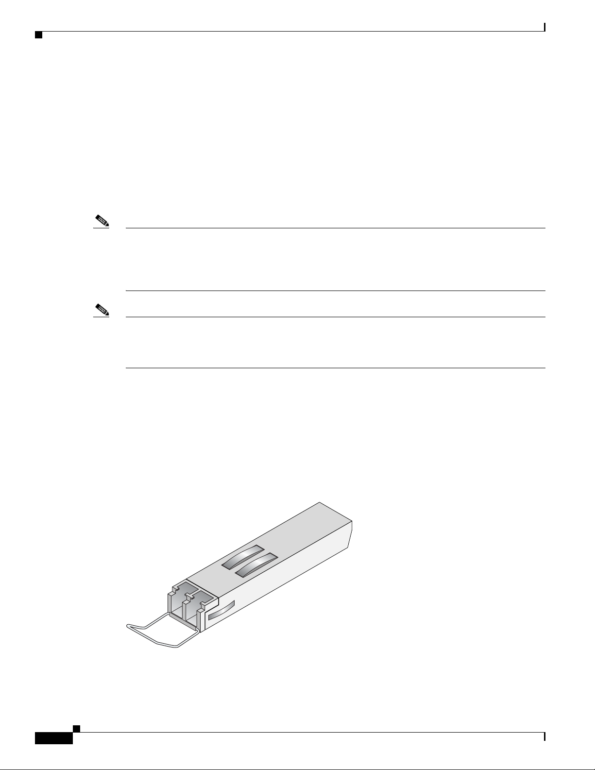
Chapter 2 Overview: Cisco XR 12000 Series Router Shared Port Adapters
127158
1-Port Channelized STM-4/OC-12 SPA Overview
1-Port Channelized STM-4/OC-12 SPA Interface Specifications
The framer processes incoming and outgoing SONET or SDH frames. The framer operates at
OC-12/STM-4 line rates (622.08 Mbps).
Packet data is transported with a user-conf igured encapsulation (such as Point-to-Point Protocol [PPP])
and is mapped into the STS-12/STM-4 frame.
The 1-Port Channelized STM-4/OC-12 SPA interface is compliant wi th RFC 1619, PPP over
SONET/SDH, and RFC 1662, PPP in HDLC-like Framing. The 1-Port Chan nelized STM-4 /OC-12 SPA
also provides support for SNMP v1 agent (RFC 1155–1157), and Management Information Base (MIB)
II (RFC 1213).
Note For Cisco IOS XR Software Release 3.8.0 and beyond, the 1-Port Channelized STM- 4/OC-12 SPA
supports Frame Relay Fragmentation (FRF.12) to achieve fragmentation of data packets and interlea ving
of voice packets. FRF .12 pro vides a method to fragment low-pri ority packets and interleav e high-priority
packets in between the low-priority fragments to provide less delay or jitter for high-priority traffic like
voice and video.
Note For Cisco IOS XR Software Release 3.8.0 and beyond, the 1-Port Channelized STM- 4/OC-12 SPA
supports Multilink Frame Relay (MFR) feature. MFR provides a mechanism for aggregating multiple
serial links into a bundle to provide greater bandwidth, load balancing between links, and improved
service availability by protecting against single point link failures.
1-Port Channelized STM-4/OC-12 SPA Cables and Connectors
The 1-Port Channelized STM-4/OC-12 SP A uses a small form-factor pluggable (SFP) optical transcei ver
module installed in each port for SONET and SDH sin gle-mode and multimode op tical f iber conn ection
(see
Figure 2-21).
Figure 2-21 SFP Optics Module
2-34
Cisco XR 12000 Series Router SIP and SPA Hardware Installation Guide
OL-17438-04
Page 65

Chapter 2 Overview: Cisco XR 12000 Series Router Shared Port Adapters
/ / / /
/ /
TXRX
The SFP optical transceiver modules used with the 1-Port Channelized STM-4/OC-12 SPA provide the
following optical fiber options:
• Multimode—622-Mbps, OC-12/STM-4 optical fiber (SONET STS-12 or SDH STM-4)
Use a multimode optical fiber that has a core/cladding diameter of 62.5/125 microns.
• Single-mode—622-Mbps, OC-12/STM-4 optical fiber (SONET STS-12 or SDH STM-4)
Use a single-mode optical fiber that has a modal-field diameter of 8.7 ±0.5 microns. (Nominal
diameter is approximately 10/125 microns.)
For single-mode and multimode optical f iber connections, you can use either a duplex LC-type cable (see
Figure 2-22) or two simplex LC-type cables, one for transmit (TX) and one for receive (RX).
Use single-mode (for intermediate- or long-reach configurations) or multimode optical fiber cable to
connect your router to a network or to connect two 1-Port Channelized STM-4/OC-12 SPA-equipped
routers back to back.
Long-range SFP optical transceiver modules (for long-reach configurations) cannot be connected
back-to-back without usin g an atten uator be tween the two of them.
Figure 2-22 LC Type Cables
1-Port Channelized STM-16/OC-48 SPA Overview
1-Port Channelized STM-16/OC-48 SPA Overview
The following sections describe the 1-Port Channelized STM-4/OC-12 SPA:
• 1-Port Channelized STM-16/OC-48 SPA LEDs, page 2-35
• 1-Port Channelized STM-16/OC-48 SPA Interface Specifications, page 2-36
• 1-Port Channelized STM-16/OC-48 SPA Cables and Connectors, page 2-37
1-Port Channelized STM-16/OC-48 SPA LEDs
The 1-Port Channelized STM-16/OC-48 SPA has two types of LEDs: an A/L LED for each port and a
STATUS LED, as shown in
OL-17438-04
Figure 2-23.
Cisco XR 12000 Series Router SIP and SPA Hardware Installation Guide
2-35
Page 66
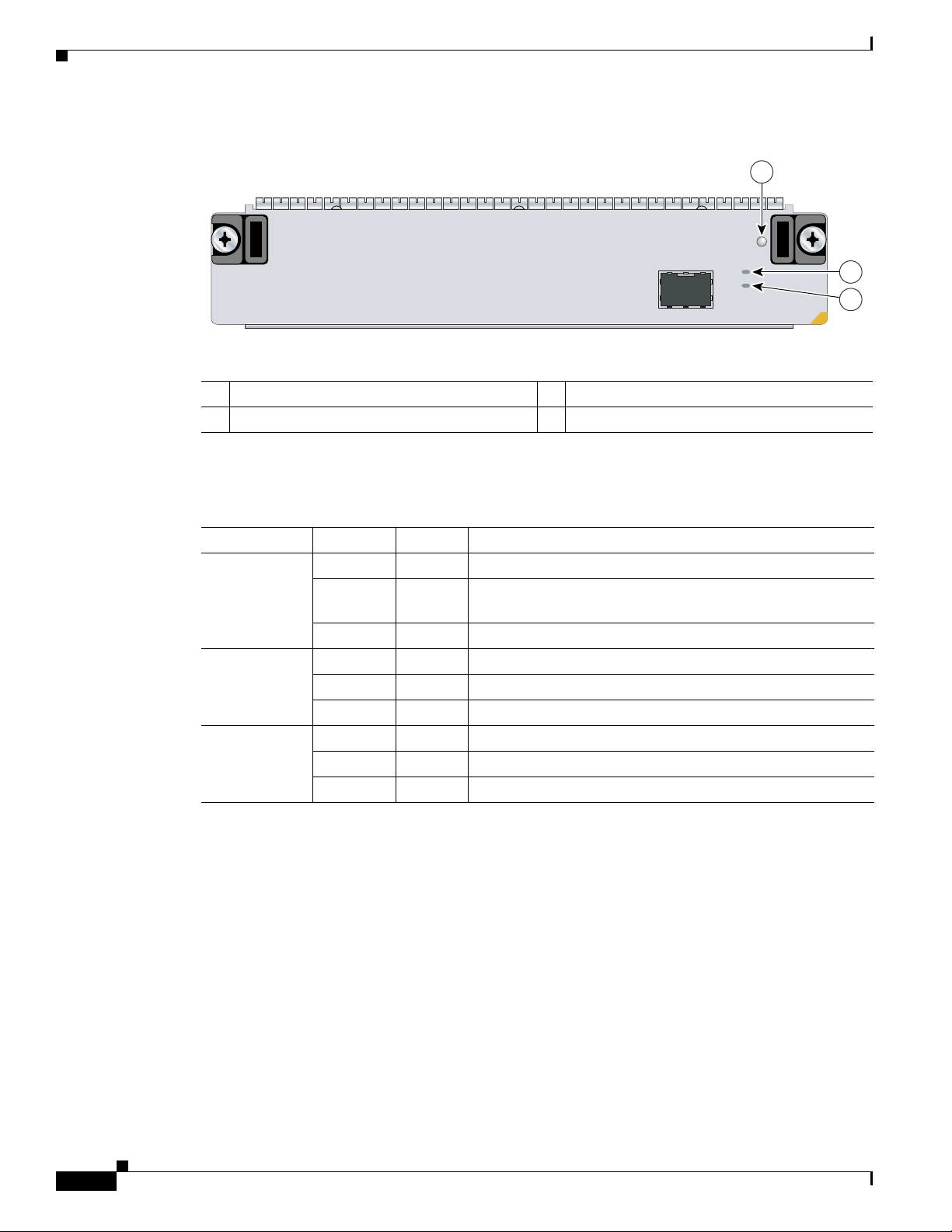
1-Port Channelized STM-16/OC-48 SPA Overview
Figure 2-23 1-Port Channelized STM-16/OC-48 SPA Faceplate
1 C/A (Carrier/Alarm) LED 3 STATUS LED
2 A/L (Active Loopback) LED
The 1-Port Channelized STM-16/OC-48 SPA LEDs are described in Table 2-30.
Chapter 2 Overview: Cisco XR 12000 Series Router Shared Port Adapters
1
SU
TA
T
S
A
/
C
L
/
A
SPA-1XCHOC48/DS3
2
3
280920
Table 2-30 1-Port Channelized STM-16/OC-48 SPA LEDs
LED Label Color State Meaning
C/A Off Off Port is not enabled by software.
Green On Port is enabled by software, and there is a valid T3 signal
without any alarms.
Amber On Port is enabled by software, and there is at least one alarm.
A/L Off Off Port is not enabled by software.
Green On Port is enabled by software, loopback is off.
Amber On Port is enabled by software, loopback is on.
STATUS Off Off SPA power is off.
Green On SPA is ready and operational.
Amber On SPA power is on and good, and SPA is being configured.
1-Port Channelized STM-16/OC-48 SPA Interface Specifications
The framer processes incoming and outgoing SONET or SDH frames. The framer operates at
OC-48/STM-16 line rates (2.488 Gbps).
Packet data is transported with a user-conf igured encapsulation (such as Point-to-Point Protocol [PPP])
and is mapped into the STS-48/STM-16 frame.
The 1-Port Channelized STM-16/OC-48 SPA interface is compliant with RFC 1619, PPP over
SONET/SDH, and RFC 1662, PPP in HDLC-like Framing. The 1-Port Channelized STM-16/OC-48 SP A
also provides support for SNMP v1 agent (RFC 1155–1157), and Management Information Base (MIB)
II (RFC 1213).
2-36
Cisco XR 12000 Series Router SIP and SPA Hardware Installation Guide
OL-17438-04
Page 67
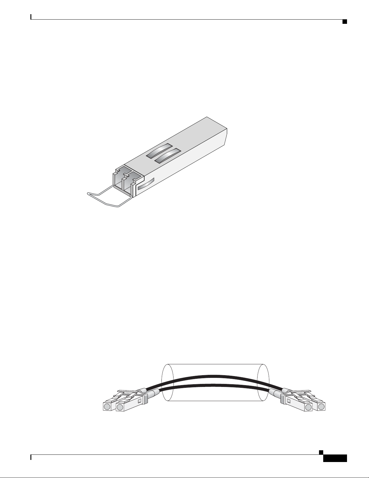
Chapter 2 Overview: Cisco XR 12000 Series Router Shared Port Adapters
127158
/ / / /
/ /
TXRX
84929
1-Port Channelized STM-16/OC-48 SPA Overview
1-Port Channelized STM-16/OC-48 SPA Cables and Connectors
The 1-Port Channelized STM-16/OC-48 SPA uses a small form-factor pluggable (SFP) optical
transceiver module inst alled in each port for SONET and SDH singl e-mode and multimode opt ical f iber
connection (see
Figure 2-24 SFP Optics Module
Figure 2-24).
The SFP optical transceiver modules used with the 1-Port Channelized STM-16/ OC-48 SPA provide the
following optical fiber options:
• Multimode—2.488-Gbps, OC-48/STM-16 optical fiber (SONET STS-48 or SDH STM-16)
Use a multimode optical fiber that has a core/cladding diameter of 62.5/125 microns.
• Single-mode—2.488-Gbps, OC-48/STM-16 optical fiber (SONET STS-48 or SDH STM-16)
Use a single-mode optical fiber that has a modal-field diameter of 8.7 ±0.5 microns. (Nominal
diameter is approximately 10/125 microns.)
For single-mode and multimode optical f iber connections, you can use either a duplex LC-type cable (see
Figure 2-25) or two simplex LC-type cables, one for transmit (TX) and one for receive (RX).
Use single-mode (for intermediate- or long-reach configurations) or multimode optical fiber cable to
connect your router to a network or to connect two 1-Port Channelized STM-16/OC-48 SPA-equipped
routers back to back.
Long-range SFP optical transceiver modules (for long-reach configurations) cannot be connected back
to back without using an attenuator between the two of them.
Figure 2-25 LC Type Cables
OL-17438-04
Cisco XR 12000 Series Router SIP and SPA Hardware Installation Guide
2-37
Page 68

Chapter 2 Overview: Cisco XR 12000 Series Router Shared Port Adapters
SPA-OC192POS LR
STATUS
MATESYNC
PASSTHRU
WRAP
ACTIVE
CARRIER
0
1
2
3
4 6
5
129138
TX RX
1-Port OC-192/STM-64 POS SPA Overview
1-Port OC-192/STM-64 POS SPA Overview
The 1-Port OC-192/STM-64 POS/RPR SPA is a double-height SPA that is installed in two SIP subslots.
The 1-Port OC-192/STM-64 POS/RPR SPA provides SONET and SDH network connectivity with a
bandwidth of 9.95
For more information about SPA bandwidth, see the “Bandwidth Oversubscription” section on page 2-2.
For more information about SPAs and their compatibility with SIPs and modular optics, see the “SIP and
SPA Compatibility” chapter in this guide.
The 1-Port OC-192/STM-64 POS/RPR SPA uses a single,10-Gbps fixed optical receptacle allowing a
connection to single-mode optical fiber. For more information on the optical fiber cables used with this
SPA, see the
Cables” section on page 2-40.
The following sections describe the 1-Port OC-192/STM-64 POS/RPR SPA:
• 1-Port OC-192/STM-64 POS/RPR SPA LEDs, page 2-38
• 1-Port OC-192/STM-64 POS/RPR SPA Interface Specifications, page 2-39
• 1-Port OC-192/STM-64 POS/RPR SPA Fixed Optical Transceiver, 40-Pin Connector, and Cables,
page 2-40
Gbps.
“1-Port OC-192/STM-64 POS/RPR SPA Fixed Optical Transceiv er , 40-Pin Connector, and
1-Port OC-192/STM-64 POS/RPR SPA LEDs
The 1-Port OC-192/STM-64 POS/RPR SPA has six LEDs, as shown in Figure 2-26.
Figure 2-26 1-Port OC-192/STM-64 POS/RPR SPA Faceplate
1 WRAP LED 4 CARRIER LED
2 PASSTHRU LED 5 ACTIVE LED
3 MATESYNC LED 6 STATUS LED
Note The WRAP, PASSTHRU, and MATESYNC LEDs apply to the SPA in RPR/SRP mode only. In
Cisco IOS Release 12.0(31)S, RPR/SRP mode is not supported.
Cisco XR 12000 Series Router SIP and SPA Hardware Installation Guide
2-38
OL-17438-04
Page 69

Chapter 2 Overview: Cisco XR 12000 Series Router Shared Port Adapters
The 1-Port OC-192/STM-64 POS/RPR SPA LEDs are described in Table 2-31.
Table 2-31 1-Port OC-192/STM-64 POS/RPR SPA LEDs
LED Label Color State Meaning
WRAP Off Off Port is not in wrap mode.
Green On Port is in wrap mode somewhere on the ring.
Amber On Port is in wrap mode locally.
PASSTHRU Off Off Port is not in pass-thru mode.
Amber On Port is in pass-thru mode.
MATESYNC Off Off Mate port is not synchronized.
Green On Mate port is synchronized.
CARRIER Off Off Port is not enabled by software.
Green On Port is enabled by software; there is a valid SONET signal
Amber On Port is enabled by software; there is at least one alarm (LOS,
Blinking Indicates SRP mode mismatch alarm.
ACTIVE Off Off Port is not enabled by software.
Green On Port is enabled by software; loopback is off.
Amber On Port is enabled by software; loopback is on.
STATUS Off Off SPA power off.
Green On SPA is ready and operational.
Amber On SPA power is on and good; SPA is being configured.
1-Port OC-192/STM-64 POS SPA Overview
without alarms.
LOF, RDI, and so on).
1-Port OC-192/STM-64 POS/RPR SPA Interface Specifications
The 1-Port OC-192/STM-64 POS/RPR SPA contains a SONET/SDH framer to process incoming and
outgoing SONET or SDH frames. The framer operates at O C-192/S TM-64 line ra tes (9.95 Gb ps).
Packet data is transported with a user-conf igured encapsulation (such as Point-to-Point Protocol [PPP])
and is mapped into the STS-192/STM-64 frame.
The 1-Port OC-192/STM-64 POS/RPR SPA interface is compliant with the following RFCs:
• RFC 1619, PPP over SONET/SDH
• RFC 1662, PPP in HDLC-like Framing
• RFC 2615, PPP over SONET/SDH
The 1-Port OC-192/STM-64 POS/RPR SPA also provides support for SNMP v1 agent (RFC 1155–1157)
and RFC 1213:
• RFC 1155, Structure and Identification of Management Information for TCP/IP-Based Internets
• RFC 1156, Management Information Base for Network Management of TCP/IP-Based Internets
• RFC 1157, Simple Network Management Protocol (SNMP)
Cisco XR 12000 Series Router SIP and SPA Hardware Installation Guide
OL-17438-04
2-39
Page 70
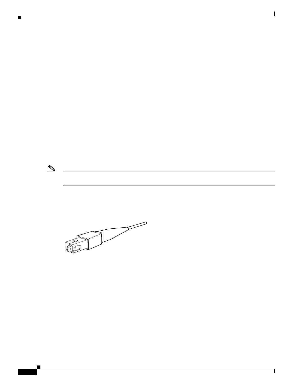
Chapter 2 Overview: Cisco XR 12000 Series Router Shared Port Adapters
38547
1-Port OC-192/STM-64 POS SPA Overview
• RFC 1213, Management Information Base (MIB) for Network Management of TCP/IP-Based
Internets:MIB II
1-Port OC-192/STM-64 POS/RPR SPA Fixed Optical Transceiver, 40-Pin Connector, and Cables
The 1-Port OC-192/STM-64 POS/RPR SP A uses f ixed optical transcei vers, one for recei ve (RX) and one
for transmit (TX), for SONET and SDH connection to the network. In Cisco IOS Release
only long-reach (LR) optics are supported.
Cisco Systems qualifies the optics that are approved for use with its SPAs. As of Cisco IOS Release
12.0(31)S and Cisco IOS XR Software Release 3.2, the XFP-10GLR-OC192SR and the
XFP-10GER-OC192IR are the only optical transceiver modules qualified for use.
The 1-Port OC-192/STM-64 POS/RPR SPA uses single-mode SC-type connectors:
• Single-mode—9.95 Gbps, OC-192 optical fiber (SONET STS-192 or SDH STM-64c)
Use a single-mode optical fiber that has a modal-field diameter of 8.7 ±0.5 microns. (Nominal diameter
is approximately 10/125 microns.)
Use a single-mode optical fiber cable to connect your router to a network.
12.0(31)S,
Note The 40-pin connector on the 1-Port OC-192/STM-64 POS/RPR SPA is used for resilient packet ring
(RPR) connections.
Figure 2-27 shows the cable type for use with the fixed optical transceiver module on the 1-Port
OC-192/STM-64 POS/RPR SPA.
Figure 2-27 SC-Type Connectors for the Fixed Optical Transceivers
Mate Interface Cables
The 1-Port OC-192/STM-64 POS/RPR SPA supports two mate interface configurations:
• Mate between two OC-192 SPAs in the same SIP
• Mate between two OC-192 SPAs in adjacent SIPs
T wo 1-Port OC-192/STM-64 POS/RPR SPAs are connected using a 40–pin connector copper mate cable.
The length of the cables allow only two possible connectio n scenarios, next slot h orizontal and same slot
vertical. This assumes that the chassis is mounted vertically.
connect the SPA s.
Figure 2-28 shows the mate cables used to
2-40
Cisco XR 12000 Series Router SIP and SPA Hardware Installation Guide
OL-17438-04
Page 71

Chapter 2 Overview: Cisco XR 12000 Series Router Shared Port Adapters
129198
1
2
Figure 2-28 SPA Mate Cables
1-Port OC-192 STM-64 POS RPR XFP SPA Overview
1 Long length RPR mate cable for single port
RPR SPAs (CBL-RPR-OC192-L)
Note The RPR mate cable is necessary only when the SPA is to be used in RPR mode. It is not needed in POS
2 Short length RPR mate cable for single port
RPR SPAs (CAB-RPR-OC192-S)
mode. Support for the RPR feature is dependent on the platform soft ware release feature content. Verify
support for the RPR feature support by reviewing the relevant SPA datasheets or by contacting your
Cisco representative.
1-Port OC-192 STM-64 POS RPR XFP SPA Overview
The 1-Port OC-192/STM-64 POS/RPR XFP SPA is a single-height SPA that is installed in one SIP
subslot. The 1-Port OC-192/STM-64 POS/RPR XFP SPA provides SONET and SDH network
connectivity with a bandwidth of 9.95
For more information about SPA bandwidth, see the “Bandwidth Oversubscription” section in this
chapter. For more information about SP As and t heir compatibi lity with SI Ps and modular optics, see the
product overview chapter in this guide.
The 1-Port OC-192/STM-64 POS/RPR XFP SPA uses a 10-Gbps small form-factor pluggable optical
receptacle for each port allowing connection to single-mode optical fiber. For more information on the
optical fiber cables used with this SPA, see the
Transceiver, 40-Pin Co nnecto r, and Cables” section on page 2-40.
Gbps.
“1-Port OC-192/STM-64 POS/RPR SPA Fixed Optical
OL-17438-04
The following sections describe the 1-Port OC-192/STM-64 POS/RPR XFP SPA:
• 1-Port OC-192/STM-64 POS/RPR XFP SPA LEDs, page 2-42
• 1-Port OC-192/STM-64 POS/RPR XFP SPA Interface Specifications, page 2-43
• 1-Port OC-192/STM-64 POS/RPR XFP SP A Optical T ranscei ver Modules, Connectors, and Cables,
page 2-43
Cisco XR 12000 Series Router SIP and SPA Hardware Installation Guide
2-41
Page 72

Chapter 2 Overview: Cisco XR 12000 Series Router Shared Port Adapters
MATESYNC
PASSTHRU
WRAP
CARRIER
ACTIVE
SPA-0C192POS-XFP
STATUS
0
129432
1
2
3 4
5
6
1-Port OC-192 STM-64 POS RPR XFP SPA Overview
1-Port OC-192/STM-64 POS/RPR XFP SPA LEDs
The 1-Port OC-192/STM-64 POS/RPR XFP SPA has six LEDs, as shown in Figure 2-29.
Figure 2-29 1-Port OC-192/STM-64 POS/RPR XFP SPA Faceplate
1 WRAP LED 4 CARRIER LED
2 PASSTHRU LED 5 ACTIVE LED
3 MATESYNC LED 6 STATUS LED
Note The WRAP, PASSTHRU, and MATESYNC LEDs apply to the SPA in RPR/SRP mode only. As of
Cisco IOS XR Software Release 3.4.0, RPR/SRP mode is not supported.
Table 2-32 describes the 1-Port OC-192/STM-64 POS/RPR XFP SPA LEDs.
Table 2-32 1-Port OC-192/STM-64 POS/RPR XFP SPA LEDs
LED Label Color State Meaning
WRAP Off Off Port is not in wrap mode.
Green On Port is in wrap mode somewhere on the ring.
Amber On Port is in wrap mode locally.
PASSTHRU Off Off Port is not in pass-thru mode.
Amber On Port is in pass-thru mode.
MATESYNC Off Off Mate port is not synchronized.
Green On Mate port is synchronized.
CARRIER Off Off Port is not enabled by software.
Green On Port is enabled by software, and there is a valid SONET sign al
without alarms.
Amber On Port is enabled by software, and ther e is at least one alarm (LOS,
LOF, RDI, and so on).
Blinking SRP mode mismatch alarm is indicated.
2-42
Cisco XR 12000 Series Router SIP and SPA Hardware Installation Guide
OL-17438-04
Page 73

Chapter 2 Overview: Cisco XR 12000 Series Router Shared Port Adapters
1-Port OC-192 STM-64 POS RPR XFP SPA Overview
Table 2-32 1-Port OC-192/STM-64 POS/RPR XFP SPA LEDs (continued)
LED Label Color State Meaning
ACTIVE Off Off Port is not enabled by software.
Green On Port is enabled by software, and loopback is off.
Amber On Port is enabled by software, and loopback is on.
STATUS Off Off SPA power off.
Green On SPA is ready and operational.
Amber On SPA power is on and good, and the SPA is being configured.
1-Port OC-192/STM-64 POS/RPR XFP SPA Interface Specifications
The framer processes incoming and outgoing SONET or SDH frames. The framer operates at
OC-192/STM-64 line rates (9.95 Gbps).
Packet data is transported with a user-conf igured encapsulation (such as Point-to-Point Protocol [PPP])
and is mapped into the STS-192/STM-64 frame.
The 1-Port OC-192/STM-64 POS/RPR XFP SPA interface is compliant with the following RFCs:
• RFC 1662, PPP in HDLC-like Framing
• RFC 2615, PPP over SONET/SDH
For information on SNMP MIB support, see “Implementing SNMP on Cisco IOS XR Software” in
Cisco
IOS XR System Management Configuration Guide.
1-Port OC-192/STM-64 POS/RPR XFP SPA Optical Transceiver Modules, Connectors, and Cables
The 1-Port OC-192/STM-64 POS/RPR XFP S PA use s a single-mode, 9.95 Gbps, OC-192 optical fiber
(SONET STS-192 or SDH STM-64) optical transceiver module for SONET and SDH connection to the
network.
The 1-Port OC-192/STM-64 POS/RPR XFP SPA supports the following types of optical transceiver
module:
• Single-mode short-reach (SR) XFP module—XFP-10GLR-OC192SR
• Single-mode intermediate-reach (IR) XFP module—XFP-10GER-OC192IR
• Single-mode very-long reach XFP module—XFP-10GZR-OC192LR
Cisco Systems qualifies the optics that are approv ed for use with its SPAs. As of Cisco IOS XR Software
Release 3.4.0, the above-listed XFPs are the only optical transceiver modules qualified for use.
Use a single-mode optical fiber that has a modal-field diameter of 8.7 ±0.5 microns (nominal diameter
is approximately 10/125 microns) to connect your router to a network.
OL-17438-04
Cisco XR 12000 Series Router SIP and SPA Hardware Installation Guide
2-43
Page 74
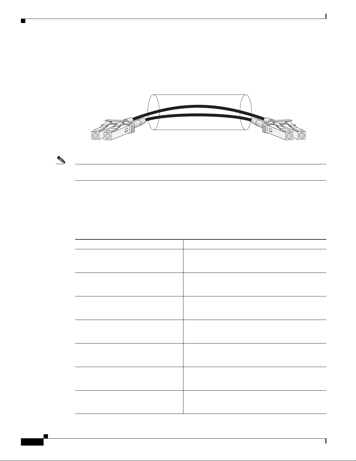
1-Port OC-192 STM-64 POS RPR XFP SPA Overview
Figure 2-30 shows the cable type for use with the XFP optical transceiver module on the 1-Port
OC-192/STM-64 POS/RPR XFP SPA.
Figure 2-30 LC-Type Cable for the XFP Optical Transceiver Modules
Chapter 2 Overview: Cisco XR 12000 Series Router Shared Port Adapters
/ /
/ / / /
Note The 40-pin connector on the 1-Port OC-192/STM-64 POS/RPR XFP SPA is used for resilient packet ring
(RPR) connections. This feature is not supported in Cisco IOS XR Software Release 3.4.0.
OC-192 Module Connections
Table 2-33 shows the OC-192 specifications for us e with the 1-Port O C-192/STM-6 4 POS/RPR XFP
SPA.
Table 2-33 OC-192 Specifications
Specification Description
Wavelength OC-192 SR-1: 1290 nm to 1330 nm
Cabling distance (maximum) OC-192 SR-1: 2 km (1.2 miles)
Operating case temperature range OC-192 SR-1: 23 to 158 degrees F (–5 to 70 degrees C)
Tx Power OC-192 SR - 1 : – 6 dBm –1 dBm
Receiver Sensitivity (maximum) OC-192 SR-1: –11 dBm
RX Overload OC-192 SR-1: –1 dBm
Maximum Receiver Power Damage OC-192 SR-1: +5 dBm
TXRX
OC-192 IR-2: 1530 nm to 1565 nm
OC-192 LR-2: 1530 nm to 1565 nm
OC-192 IR-2: 40 km (24.8 miles)
OC-192 LR-2: 50 miles (80 km)
OC-192 IR-2: 23 to 158 degrees F (–5 to 70 degrees C)
OC-192 LR-2: 23 to 158 degrees F (–5 to 70 degrees C)
OC-192 IR-2: –1 dBm +2 dBm
OC-192 LR-2: 0 to +4 dBm
OC-192 IR-2: –14 dBm
OC-192 LR-2: –24 dBm
OC-192 IR-2: +2 dBm
OC-192 LR-2: –7.0 dBm
OC-192 IR-2: +5 dBm
OC-192 LR-2: +5 dBm
84929
2-44
Cisco XR 12000 Series Router SIP and SPA Hardware Installation Guide
OL-17438-04
Page 75
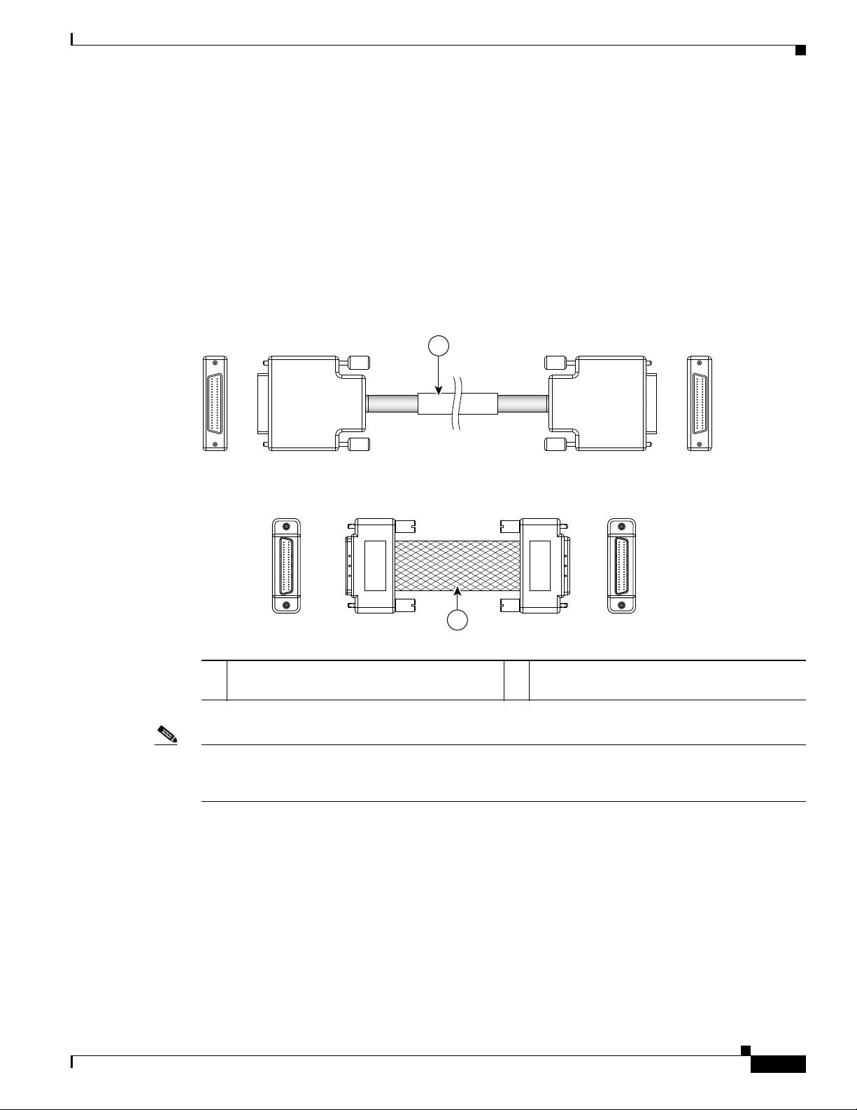
Chapter 2 Overview: Cisco XR 12000 Series Router Shared Port Adapters
129198
1
2
Mate Interface Cables
The 1-Port OC-192/STM-64 POS/RPR XFP SPA supports two mate interface configurations:
• Mate between two OC-192 SPAs in the same SIP
• Mate between two OC-192 SPAs in adjacent SIPs
T w o 1-Port OC-192/STM-64 POS/RPR XFP SPAs are connected using a 40–pin connector copper mate
cable. The length of the cables allow only two possible connection scenarios, next slot horizontal and
same slot vertical. This assumes that the chassis is mounted v ertically .
used to connect the SPAs.
Figure 2-31 SPA Mate Cables
4-Port OC-3/STM-1 POS SPA Overview
Figure 2-31 shows the mate cables
1 Long length RPR mate cable for single port
RPR SPAs (CBL-RPR-OC192-L)
Note The RPR mate cable is necessary only when the SPA is to be used in RPR mode. It is not needed in POS
mode. Support for the RPR feature is dependent on the platform soft ware release feature content. Verify
support for the RPR feature support via SPA datasheets or by contacting your Cisco representative.
4-Port OC-3/STM-1 POS SPA Overview
The 2-Port and 4-Port OC-3/STM-1 POS SPA is a single-height SPA that installs into one SIP subslot.
The OC-3c/STM-1 POS SPA with small form-factor pluggable (SFP) optical transceiver modules
provides SONET and SDH network conn ectivity with a per-port bandwidth of 155.52 Mbps. The 2-Port
and 4-Port OC-3/STM-1 POS SPA operates at quarter rate.
Cisco XR 12000 Series Router SIP and SPA Hardware Installation Guide
OL-17438-04
2 Short length RPR mate cable for single port
RPR SPAs (CAB-RPR-OC192-S)
2-45
Page 76

Chapter 2 Overview: Cisco XR 12000 Series Router Shared Port Adapters
STATUS
0
1
2
3
A/L
C/A
A/L
C/A
A/L
C/A
A/L
C/A
122938
1
2 3
4-Port OC-3/STM-1 POS SPA Overview
Note When SFP modules are replaced, the SPA interface retains any previously defined configur ations. These
configurations include settings for IP address, clock source, loopback, Cyclic Redundancy Check
(CRC), and POS flags.
For more information about SPA bandwidth, see the “Bandwidth Oversubscription” section in this
chapter. For more information about SP As and t heir compatibi lity with SI Ps and modular optics, see the
“SIP and SPA Product Overview” chapter in this guide.
The following sections describe the 2-Port and 4-Port OC-3/STM-1 POS SPA:
• 2-Port and 4-Port OC-3/STM-1 POS SPA LEDs, page 2-46
• 2-Port and 4-Port OC-3/STM-1 POS SPA Interface Specifications, page 2-47
• 2-Port and 4-Port OC-3/STM-1 POS SPA Optical Transceiver Modules and Cables, page 2-47
2-Port and 4-Port OC-3/STM-1 POS SPA LEDs
The 2-Port and 4-Port OC-3/STM-1 POS SPA has three types of LEDs: two LEDs for each port on the
SPA and one STATUS LED.
Figure 2-32 shows the 4-Port OC-3/STM-1 POS SPA.
Figure 2-32 4-Port OC-3/STM-1 POS SPA Faceplate
1 C/A (Carrier/Alarm) LED 3 STATUS LED
2 A/L (Active/Loopback) LED
Table 2-34 describes the 2-Port and 4-Port OC-3/STM-1 POS SPA LEDs.
Table 2-34 2-Port and 4-Port OC-3/STM-1 POS SPA LEDs
LED Label Color State Meaning
C/A Off Off SONET controller is shut down.
Green On Port is enabled by software, and there is a valid SONET signal
without any alarms.
Amber On Port is enabled by software, and there is at least one alarm.
A/L Off Off Interface is shut down.
Green On Port is enabled by software, and loopback is off.
Amber On Port is enabled by software, and loopback is on.
2-46
Cisco XR 12000 Series Router SIP and SPA Hardware Installation Guide
OL-17438-04
Page 77

Chapter 2 Overview: Cisco XR 12000 Series Router Shared Port Adapters
4-Port OC-3/STM-1 POS SPA Overview
Table 2-34 2-Port and 4-Port OC-3/STM-1 POS SPA LEDs (continued)
LED Label Color State Meaning
STATUS Off Off SPA power is off.
Green On SPA is ready and operational.
Amber On SPA power is on and good, and the SPA is being configured.
2-Port and 4-Port OC-3/STM-1 POS SPA Interface Specifications
The framer processes incoming and outgoing SONET or SDH frames. The framer operates at
OC-3c/STM-1 line rates (155.52 Mbps).
Packet data is transported with a user-conf igured encapsulation (such as Point-to-Point Protocol [PPP])
and is mapped into the STS-3c/STM-1 frame.
The 2-Port and 4-Port OC-3/STM-1 POS SPA interface complies with the following RFCs:
• RFC 1662, PPP in HDLC-like Framing
• RFC 2427, Multiprotocol Interconnect over Frame Relay
• RFC 2615, PPP over SONET/SDH
2-Port and 4-Port OC-3/STM-1 POS SPA Optical Transceiver Modules and Cables
The 2-Port and 4-Port OC-3/STM-1 POS SPA uses a small form-factor pluggable (SFP) optical
transceiver module inst alled in each port for SONET and SDH singl e-mode and multimode opt ical f iber
connection (see
Cisco Systems qualifies the optics that are approved for use with its SPAs. The 2-Port and 4-Port
OC-3/STM-1 POS SPA supports the following types of optical transceiver modules:
• Multimode (MM) SFP module—SFP-OC3-MM
• Short-reach (SR) SFP module—SFP-OC3-SR
• Intermediate-reach (IR) SFP module (15 km)—SFP-OC3-IR1
• Long-reach (LR) SFP module (40 km)—SFP-OC3-LR1
• Long-reach (LR) SFP module (80 km)—SFP-OC3-LR2
Figure 2-33).
OL-17438-04
Cisco XR 12000 Series Router SIP and SPA Hardware Installation Guide
2-47
Page 78

4-Port OC-3/STM-1 POS SPA Overview
127158
/ / / /
/ /
TXRX
84929
Figure 2-33 SFP Optics Module
The SFP optical transceiver modules used with the 2-Port and 4-Port OC-3/STM-1 POS SPA provide the
following optical fiber options:
• Multimode—155-Mbps, OC-3c/STM-1 optical fiber (SONET STS-3c or SDH STM-1)
Use a multimode optical fiber that has a core/cladding diameter of 62.5/125 microns.
• Single-mode—155-Mbps, OC-3c/STM-1 optical fiber (SONET STS-3c or SDH STM-1)
Chapter 2 Overview: Cisco XR 12000 Series Router Shared Port Adapters
Use a single-mode optical fiber that has a modal-field diameter of 8.7 ± 0.5 microns. (Nominal
diameter is approximately 10/125 microns.)
For single-mode and multimode optical f iber connections, you can use either a duplex LC-type cable (see
Figure 2-34) or two simplex LC-type cables, one for transmit (TX) and one for receive (RX).
Use single-mode (for intermediate-reach or long-reach configurations) or multimode optical fiber cable
to connect your router to a network or to connect two 2-Port and 4 -Port OC-3/STM-1 POS SPA-equipped
routers back-to-back.
Long-range SFP optical transceiver modules (for long-reach configurations) cannot be connected
back-to-back without usin g an atten uator be tween the m.
Figure 2-34 LC-Type Cable
Cisco XR 12000 Series Router SIP and SPA Hardware Installation Guide
2-48
OL-17438-04
Page 79

Chapter 2 Overview: Cisco XR 12000 Series Router Shared Port Adapters
OC-3 Module Connections
Table 2-35 shows the OC-3 specifications of the optics on the 2-Port and 4-Port OC-3/STM-1 POS SPA.
Table 2-35 OC-3 Specifications
Specification Description
Wavelength OC-3 MM: 1270 nm to 1380 nm
Cabling distance (maximum) OC-3 MM: 2 km (1.2 miles)
Operating case temperature range OC-3 MM: 23 to 185 degrees F (–5 to 85 degrees C)
TX power OC-3 MM: –19 to –14 dBm
Receiver sensitivity (maximum) OC-3 MM: –30 dBm
RX over lo a d OC-3 MM: –5 dBm
Maximum receiver power damage OC-3 MM: +5 dBm
4-Port OC-3/STM-1 POS SPA Overview
OC-3 SR: 1260 nm to 1360 nm
OC-3 IR-1: 1261 nm to 1360 nm
OC-3 LR-1: 1263 nm to1360 nm
OC-3 LR-2: 1480 nm to 1580 nm
OC-3 SR: 2 km (1.2 miles)
OC-3 IR-1: 15 km (9.3 miles)
OC-3 LR-1: 40 km (24.8 miles)
OC-3 LR-2: 80 km (49.7 miles)
OC-3 SR: 23 to 185 degrees F (–5 to 85 degrees C)
OC-3 IR-1: 23 to 185 degrees F (–5 to 85 degrees C)
OC-3 LR-1: 23 to 185 degrees F (–5 to 85 degrees C)
OC-3 LR-2: 23 to 185 degrees F (–5 to 85 degrees C)
OC-3 SR: –15 to –8 dBm
OC-3 IR-1: –15 to –8 dBm
OC-3 LR-1: –5 to 0 dBm
OC-3 LR-2: –5 to 0 dBm
OC-3 SR: –23 dBm
OC-3 IR-1: –28 dBm
OC-3 LR-1: –34 dBm
OC-3 LR-2: –34 dBm
OC-3 SR: –8 dBm
OC-3 IR-1: –8 dBm
OC-3 LR-1: –10 dBm
OC-3 LR-2: –10 dBm
OC-3 SR: +5 dBm
OC-3 IR-1: +5 dBm
OC-3 LR-1: +5 dBm
OC-3 LR-2: +5 dBm
OL-17438-04
Cisco XR 12000 Series Router SIP and SPA Hardware Installation Guide
2-49
Page 80

Chapter 2 Overview: Cisco XR 12000 Series Router Shared Port Adapters
STATUS
SPA-8XOC12-POS
138896
3
3
C/A
A/L
0
C/A
A/L
1
C/A
A/L
2
C/A
A/L
21
4
C/A
A/L
5
C/A
A/L
6
C/A
A/L
7
C/A
A/L
8-Port OC-3 STM-1/OC-12 STM-4 POS SPA Overview
8-Port OC-3 STM-1/OC-12 STM-4 POS SPA Overview
The 8-Port OC-3 STM-1/OC-12 STM-4 POS SPA is a single-height SPA that installs into one SIP
subslot. The SPA with small form-factor pluggable (SFP) optical transceiver modules provides Optical
Carrier Level (OC-n) for SONET and Synchronous Transport Module (STM-n) for SDH network
connectivity. On this SPA, any given port can use either an OC-3 or OC-12 SFP module, so the per-port
bandwidth can be either 155.52
configuration.
Note When SFP modules are replaced, the SPA interface retains any previously defined configur ations. These
configurations include settings for IP address, clock source, loopback, CRC, and POS flags.
For more information about SPA bandwidth, see the “Bandwidth Over subscription” topic in this chapter.
For more information about SPAs and their compatibility with SIPs and modular optics, see the “SIP and
SPA Product Overview” chapter in this guide.
The following sections describe the 8-Port OC-3 STM-1/OC-12 STM-4 POS SPA:
• 8-Port OC-3 STM-1/OC-12 STM-4 POS SPA LEDs, page 2-50
• 8-Port OC-3 STM-1/OC-12 STM-4 POS SPA Interface Specifications, page 2-51
Mbps or 622.08 Mbps, respectively, depending on the customer
• 8-Port OC-3 STM-1/OC-12 STM-4 POS SPA Optical Transceiver Modules and Cables, page 2-51
8-Port OC-3 STM-1/OC-12 STM-4 POS SPA LEDs
The 8-Port OC-3 STM-1/OC-12 STM-4 POS SPA has three types of LEDs: t wo LEDs for each port on
the SPA and one STATUS LED.
faceplate.
Figure 2-35 8-Port OC-3 STM-1/OC-12 STM-4 POS SPA Faceplate
1 C/A (Carrier/Alarm) LED 3 STATUS LED
2 A/L (Active/Loopback) LED
Figure 2-35 shows the 8-Port OC-3 STM-1/OC-12 STM-4 POS SPA
2-50
Cisco XR 12000 Series Router SIP and SPA Hardware Installation Guide
OL-17438-04
Page 81

Chapter 2 Overview: Cisco XR 12000 Series Router Shared Port Adapters
Table 2-36 describes the 8-Port OC-3 STM-1/OC-12 STM-4 POS SPA LEDs.
Table 2-36 8-Port OC-3 STM-1/OC-12 STM-4 POS SPA LEDs
LED Label Color State Meaning
C/A Off Off SONET controller is shut down.
Green On Port is enabled by software, and there is a valid SONET signal
Amber On Port is enabled by software, and there is at least one alarm.
A/L Off Off Interface is shut down.
Green On Port is enabled by software, and loopback is off.
Amber On Port is enabled by software, and loopback is on.
STATUS Off Off SPA power is off.
Green On SPA is ready and operational.
Amber On SPA power is on and good, and the SPA is being configured.
8-Port OC-3 STM-1/OC-12 STM-4 POS SPA Overview
without any alarms.
8- Po r t O C - 3 S T M-1/ O C-12 S TM-4 P OS S PA Interface Specifications
The framer processes incoming and outgoing SONET or SDH frames. The framer operates at OC-3 line
rates (155.52 Mbps) and OC-12 line rates (622.08 Mbps). Packet data is transported with a
user-configured encapsulation (such as Point-to-Point Protocol [PPP]) and is mapped into the Layer
frame.
The 8-Port OC-3 STM-1/OC-12 STM-4 POS SPA interface complies with the following RFCs:
• RFC 1662, PPP in HDLC-like Framing
• RFC 2427, Multiprotocol Interconnect over Frame Relay
• RFC 2615, PPP over SONET/SDH
2
8-Port OC-3 STM-1/OC-12 STM-4 POS SPA Optical Transceiver Modules and Cables
The 8-Port OC-3 STM-1/OC-12 STM-4 POS SPA uses a small form-factor pluggable (SFP) optical
transceiver module inst alled in each port for SONET and SDH singl e-mode and multimode opt ical f iber
connections (see
Cisco Systems qualifies the optics that are approved for use with its SPAs. The following OC-3 optical
transceiver modules are supported on the 8-Port OC-3 STM-1/OC-12 STM-4 POS SPA:
• Multimode (MM) SFP module—SFP-OC3-MM
• Short-reach (SR) SFP module—SFP-OC3-SR
• Intermediate-reach (IR) SFP module (15 km)—SFP-OC3-IR1
Figure 2-36).
OL-17438-04
• Long-reach (LR) SFP module (40 km)—SFP-OC3-LR1
• Long-reach (LR) SFP module (80 km)—SFP-OC3-LR2
Cisco XR 12000 Series Router SIP and SPA Hardware Installation Guide
2-51
Page 82

8-Port OC-3 STM-1/OC-12 STM-4 POS SPA Overview
127158
The following OC-12 optical transceiver modules are supported on the 8-Port OC-3 STM-1/OC-12
STM-4 POS SPA:
• Multimode (MM) SFP module—SFP-OC12-MM
• Short-reach (SR) SFP module—SFP-OC12-SR
• Intermediate-reach (IR) SFP module (15 km)—SFP-OC12-IR1
• Long-reach (LR) SFP module (40 km)—SFP-OC12-LR1
• Long-reach (LR) SFP module (80 km)—SFP-OC12-LR2
Figure 2-36 SFP Optics Module
Chapter 2 Overview: Cisco XR 12000 Series Router Shared Port Adapters
The following OC-3 optical fiber options are available for the 8-Port OC-3 STM-1/OC-12 STM-4 POS
SPA:
• Multimode—155.52-Mbps, OC-3 optical fiber (SONET STS-3c or SDH STM-1)
Use a multimode optical fiber that has a core/cladding diameter of 62.5/125 microns.
• Single-mode—155.52-Mbps, OC-3 optical fiber (SONET STS-3c or SDH STM-1)
Use a single-mode optical fiber that has a modal-field diameter of 8.7 ± 0.5 microns. (Nominal
diameter is approximately 10/125 microns.)
The following OC-12 optical fiber options are a v ailable for the 8-Port OC-3 STM-1/OC-12 STM-4 POS
SPA:
• Multimode—622.08-Mbps, OC-12 optical fiber (SONET STS-12c or SDH STM-4)
Use a multimode optical fiber that has a core/cladding diameter of 62.5/125 microns.
• Single-mode—622.08-Mbps, OC-12 optical fiber (SONET STS-12c or SDH STM-4)
Use a single-mode optical fiber that has a modal-field diameter of 8.7 ± 0.5 microns. (Nominal
diameter is approximately 10/125 microns.)
For single-mode and multimode optical f iber connections, you can use either a duplex LC-type cable (see
Figure 2-37) or two simplex LC-type cables, one for transmit (TX) and one for receive (RX).
Use single-mode (for short-, intermediate- or long-reach configurations) or multimode optical fiber
cable to connect your router to a network or two OC-3-equipped or OC-12-equipped routers
back-to-back.
Long-range SFP optical transceiver modules (for long-reach configurations) cannot be connected
back-to-back without usin g an atten uator be tween the m.
2-52
Cisco XR 12000 Series Router SIP and SPA Hardware Installation Guide
OL-17438-04
Page 83

Chapter 2 Overview: Cisco XR 12000 Series Router Shared Port Adapters
/ / / /
/ /
TXRX
84929
Figure 2-37 LC-Type Cable
OC-3 Module Connections
Table 2-37 shows the OC-3 specifications of the optics on the 8-Port OC-3 STM-1/OC-12 STM-4 POS
SPA.
Table 2-37 OC-3 Specifications
Specification Description
Wavelength OC-3 MM: 1270 nm to 1380 nm
Cabling distance (maximum) OC-3 MM: 2 km (1.2 miles)
Operating case temperature range OC-3 MM: 23 to 185 degrees F (–5 to 85 degrees C)
TX power OC-3 MM: –19 to –14 dBm
Receiver sensitivity (maximum) OC-3 MM: –30 dBm
8-Port OC-3 STM-1/OC-12 STM-4 POS SPA Overview
OC-3 SR: 1260 nm to 1360 nm
OC-3 IR-1: 1261 nm to 1360 nm
OC-3 LR-1: 1263 nm to1360 nm
OC-3 LR-2: 1480 nm to 1580 nm
OC-3 SR: 2 km (1.2 miles)
OC-3 IR-1: 15 km (9.3 miles)
OC-3 LR-1: 40 km (24.8 miles)
OC-3 LR-2: 80 km (49.7 miles)
OC-3 SR: 23 to 185 degrees F (–5 to 85 degrees C)
OC-3 IR-1: 23 to 185 degrees F (–5 to 85 degrees C)
OC-3 LR-1: 23 to 185 degrees F (–5 to 85 degrees C)
OC-3 LR-2: 23 to 185 degrees F (–5 to 85 degrees C)
OC-3 SR: –15 to –8 dBm
OC-3 IR-1: –15 to –8 dBm
OC-3 LR-1: –5 to 0 dBm
OC-3 LR-2: –5 to 0 dBm
OC-3 SR: –23 dBm
OC-3 IR-1: –28 dBm
OC-3 LR-1: –34 dBm
OC-3 LR-2: –34 dBm
OL-17438-04
Cisco XR 12000 Series Router SIP and SPA Hardware Installation Guide
2-53
Page 84

8-Port OC-3 STM-1/OC-12 STM-4 POS SPA Overview
Table 2-37 OC-3 Specifications (continued)
Specification Description
RX over lo a d OC-3 MM: –5 dBm
Maximum receiver power damage OC-3 MM: +5 dBm
OC-12 Module Connections
Table 2-38 shows the OC-12 specifications of the optics on the 8-Port OC-3 STM-1/OC-12 STM-4 POS
SPA.
Chapter 2 Overview: Cisco XR 12000 Series Router Shared Port Adapters
OC-3 SR: –8 dBm
OC-3 IR-1: –8 dBm
OC-3 LR-1: –10 dBm
OC-3 LR-2: –10 dBm
OC-3 SR: +5 dBm
OC-3 IR-1: +5 dBm
OC-3 LR-1: +5 dBm
OC-3 LR-2: +5 dBm
Table 2-38 OC-12 Specifications
Specification Description
Wavelength OC-12 MM: 1270 nm to 1380 nm
OC-12 SR: 1261 nm to 1360 nm
OC-12 IR-1: 1293 nm to 1334 nm
OC-12 LR-1: 1280 nm to 1335 nm
OC-12 LR-2: 1480 nm to 1580 nm
Cabling distance (maximum) OC-12 MM: 0.5 km (0.3 miles)
OC-12 SR: 2 km (1.2 miles)
OC-12 IR-1: 15 km (9.3 miles)
OC-12 LR-1: 40 km (24.8 miles)
OC-12 LR-2: 80 km (49.7 miles)
Operating case temperature range OC-12 MM: 23 to 185 degrees F (–5 to 85 degrees C)
OC-12 SR: 23 to 185 degrees F (–5 to 85 degrees C)
OC-12 IR-1: 23 to 185 degrees F (–5 to 85 degrees C)
OC-12 LR-1: 23 to 185 degrees F (–5 to 85 degrees C)
OC-12 LR-2: 23 to 185 degrees F (–5 to 85 degrees C)
TX power OC-12 MM: –20 to –14 dBm
OC-12 SR: –15 to –8 dBm
OC-12 IR-1: –15 to – 8 dBm
OC-12 LR-1: –3 to 2 dBm
OC-12 LR-2: –3 to 2 dBm
Receiver sensitivity (maximum) OC-12 MM: –26 dB
OC-12 SR: –23 dBm
OC-12 IR-1: –28 dBm
OC-12 LR-1: –28 dBm
OC-12 LR-2: –28 dBm
2-54
Cisco XR 12000 Series Router SIP and SPA Hardware Installation Guide
OL-17438-04
Page 85

Chapter 2 Overview: Cisco XR 12000 Series Router Shared Port Adapters
SPA-1XOC12-POS
STATUS
0
A/L
C/A
1
2
3
129137
Table 2-38 OC-12 Specifications (continued)
Specification Description
RX over lo a d OC-12 MM: –6 dBm
Maximum receiver power damage OC-12 MM: +5 dBm
1-Port OC-12/STM-4 POS SPA Overview
OC-12 SR: –8 dBm
OC-12 IR-1: –8 dBm
OC-12 LR-1: –8 dBm
OC-12 LR-2: –8 dBm
OC-12 SR: +5 dBm
OC-12 IR-1: +5 dBm
OC-12 LR-1: +5 dBm
OC-12 LR-2: +5 dBm
1-Port OC-12/STM-4 POS SPA Overview
The 1-Port OC-12/STM-4 POS SPA is single-height SPA that installs into one SIP subslot. The 1-Port
OC-12/STM-4 POS SPA with a small form-factor pluggable (SFP) optical transceiver module provides
SONET an d S DH ne twor k c on ne ct ivity wit h a ba nd wi dth of 622.08 Mbps.
For more information about SPA bandwidth, see the “Bandwidth Over subscription” topic in this chapter .
For more information about SPAs and their compatibility with SIPs and modular optics, see the “SIP and
SPA Product Overview” chapter in this guide.
The following sections describe the 1-Port OC-12/STM-4 POS SPA:
• 1-Port OC-12/STM-4 POS SPA LEDs, page 2-55
• 1-Port OC-12/STM-4 POS SPA Interface Specifications, page 2-56
• 1-Port OC-12/STM-4 POS SPA SFP Optical Transceiver Modules and Cables, page 2-56
1-Port OC-12/STM-4 POS SPA LEDs
The 1-Port OC-12/STM-4 POS SPA has three types of LEDs. There are two LEDs for each port on the
SPA, and one STATUS LED.
POS SPA.
Figure 2-38 1-Port OC-12/STM-4 POS SPA Faceplate
Figure 2-38 shows an example of these LEDs on a 1-Port OC-12/STM-4
OL-17438-04
Cisco XR 12000 Series Router SIP and SPA Hardware Installation Guide
2-55
Page 86

1-Port OC-12/STM-4 POS SPA Overview
1 C/A (Carrier/Alarm) LED 3 STATUS LED
2 A/L (Active Loopback) LED
The 1-Port OC-12/STM-4 POS SPA LEDs ar e described in Table 2-39.
Table 2-39 1-Port OC-12/STM-4 POS SPA LEDs
LED Label Color State Meaning
C/A Off Off Port is not enabled by software.
A/L Off Off Port is not enabled by software.
STATUS Off Off SPA power is off.
Chapter 2 Overview: Cisco XR 12000 Series Router Shared Port Adapters
Green On Port is enabled by software, and there is a valid SONET signal
without any alarms.
Amber On Port is enabled by software, and there is at least one alarm.
Green On Port is enabled by software, loopback is off.
Amber On Port is enabled by software, loopback is on.
Green On SPA is ready and operational.
Amber On SPA power is on and good; SPA is being configured.
1-Port OC-12/STM-4 POS SPA Interface Specifications
The framer processes incoming and outgoing SONET or SDH frames. The framer operates at
OC-12/STM-4 line rates (622.08 Mbps).
Packet data is transported with a user-conf igured encapsulation (such as Point-to-Point Protocol [PPP])
and is mapped into the STS-12/STM-4 frame.
The 1-Port OC-12/STM-4 POS SPA interface is compliant with the following RFCs:
• RFC 1619, PPP over SONET/SDH
• RFC 1662, PPP in HDLC-like Framing
The 1-Port OC-12/STM-4 POS SPA also provides support for SNMP v1 agent (RFC 1155–1157) and
RFC 1213:
• RFC 1155, Structure and Identification of Management Information for TCP/IP-based Internets
• RFC 1156, Management Information Base for Network Management of TCP/IP-Based Internets
• RFC 1157, Simple Network Management Protocol (SNMP)
• RFC 1213, Management Information Base (MIB) for Network Management of TCP/IP-Based
Internets:MIB II.
1-Port OC-12/STM-4 POS SPA SFP Optical Transceiver Modules and Cables
The POS SP A uses a small form- factor pluggable (SFP) optical transcei ve r module installed in each port
for SONET and SDH single-mode and multimode optical fiber connection (see
Figure 2-39).
2-56
Cisco XR 12000 Series Router SIP and SPA Hardware Installation Guide
OL-17438-04
Page 87

Chapter 2 Overview: Cisco XR 12000 Series Router Shared Port Adapters
127158
Cisco Systems qualifies the optics that are approved for use with its SPAs. The 1-Port OC-12/STM-4
POS SPA supports the following types of optical transceiver modules:
• Multimode (MM) SFP module—SFP-OC12-MM
• Short reach (SR) SFP module—SFP-OC12-SR
• Intermediate reach (IR) SFP module (15 km)—SFP-OC12-IR1
• Long reach (LR) SFP module (40 km)—SFP-OC12-LR1
• LR SFP module (80 km)—SFP-OC12-LR2
Figure 2-39 SFP Optics Module
1-Port OC-12/STM-4 POS SPA Overview
The SFP optical transceiver modules used with the POS SPAs provide the following optical fiber optio ns:
• Multimode—622.08-Mbps, OC-12 optical fiber (SONET STS-12 or SDH STM-4)
Use a multimode optical fiber that has a core/cladding diameter of 62.5/125 microns.
• Single-mode—622.08-Mbps, OC-12 optical fiber (SONET STS-12 or SDH STM-4)
Use a single-mode optical fiber that has a modal-field diameter of 8.7 ±0.5 microns. (Nominal
diameter is approximately 10/125 microns.)
For single-mode and multimode optical f iber connections, you can use either a duplex LC-type cable (see
Figure 2-40) or two simplex LC-type cables, one for transmit (TX) and one for receive (RX).
Use single-mode (for intermediate- or long-reach configurations) or multimode optical fiber cable to
connect your router to a network or to connect two 1-Port OC-12/STM-4 POS SPA-equipped routers
back to back.
Long-range SFP optical transceiver modules (for long-reach configurations) cannot be connected
back-to-back without usin g an atten uator be tween the two of them.
OL-17438-04
Cisco XR 12000 Series Router SIP and SPA Hardware Installation Guide
2-57
Page 88

1-Port OC-48/STM-16 POS SPA Overview
SPA-1XOC48POS/RPR
MATESYNC
PASSTHRU
WRAP
ACTIVE
CARRIER
SPA-1XOC12-POS
STATUS
0
A/L
C/A
4
1
2
5
6
3
7
8
149965
Figure 2-40 LC-Type Cable
Chapter 2 Overview: Cisco XR 12000 Series Router Shared Port Adapters
/ /
/ / / /
TXRX
1-Port OC-48/STM-16 POS SPA Overview
The 1-Port OC-48/STM-16 POS SPA is a single-height SPA that is installed in a SIP subslot. The
1-Port
OC-48/STM-16 POS SPA provides RPR over SONET (IEEE 802.17), SRP over SONET (Cisco
Proprietary), and Packet over SONET (POS) network connectivity with a bandwidth of 9.95
For more information about SPA bandwidth, see the “Bandwidth Ov ersubscription” topic in this chapter.
For more information about SPAs and their compatibility with SIPs and modular optics, see the “SIP and
SPA Product Overview” chapter in this guide.
The following sections describe the 1-Port OC-48/STM-16 POS SPA:
• 1-Port OC-48/STM-16 POS SPA LEDs, page 2-58
• 1-Port OC-48/STM-16 POS SPA Interface Specifications, page 2-59
• 1-Port OC-48/STM-16 POS SPA Optical Transceiver Modules, Connectors, and Cables, page 2-60
1-Port OC-48/STM-16 POS SPA LEDs
The 1-Port OC-48/STM-16 POS SPA has six LEDs, as shown in Figure 2-41.
84929
Gbps.
2-58
Figure 2-41 1-Port OC-48/STM-16 POS SPA Faceplate
1 WRAP LED 5 CARRIER LED
2 PASSTHRU LED 6 ACTIVE LED
3 MATESYNC LED 7 A/L (Active Loopback) LED
4 C/A (Carrier/Alarm) LED 8 STATUS LED
Cisco XR 12000 Series Router SIP and SPA Hardware Installation Guide
OL-17438-04
Page 89

Chapter 2 Overview: Cisco XR 12000 Series Router Shared Port Adapters
Note The WRAP, PASSTHRU, and MATESYNC LEDs apply to the SPA in RPR/SRP mode only.
The 1-Port OC-48/STM-16 POS SPA LEDs are described in Table 2-40.
Table 2-40 1-Port OC-48/STM-16 POS SPA LEDs
LED Label Color State Meaning
WRAP Off Off Port is not in wrap mode.
Green On Port is in wrap mode somewhere on the ring.
Amber On Port is in wrap mode locally.
PASSTHRU Off Off Port is not in pass-thru mode.
Amber On Port is in pass-thru mode.
MATESYNC Off Off Mate port is not synchronized.
Green On Mate port is synchronized.
C/A Off Off Port is not enabled by software.
Green On Port is enabled by software.
Amber On Port is enabled by software, and there is at least one alarm.
A/L Off Off Port is not enabled by software.
Green On Port is enabled by software, loopback is off.
Amber On Port is enabled by software, loopback is on.
CARRIER Off Off Port is not enabled by software.
Green On Port is enabled by software; there is a valid SONET signal
Amber On Port is enabled by software; there is at least one alarm (LOS,
Blinking Indicates SRP mode mismatch alarm.
ACTIVE Off Off Port is not enabled by software.
Green On Port is enabled by software; loopback is off.
Amber On Port is enabled by software; loopback is on.
STATUS Off Off SPA power off.
Green On SPA is ready and operational.
Amber On SPA power is on and good; SPA is being configured.
1-Port OC-48/STM-16 POS SPA Overview
without alarms.
LOF, RDI, and so on).
1-Port OC-48/STM-16 POS SPA Interface Specifications
The framer processes incoming and outgoing SONET or SDH frames. The framer operates at
OC-48/STM-64 line rates (9.95 Gbps).
Packet data is transported with a user-conf igured encapsulation (such as Point-to-Point Protocol [PPP])
and is mapped into the STS-48/STM-64 frame.
Cisco XR 12000 Series Router SIP and SPA Hardware Installation Guide
OL-17438-04
2-59
Page 90

Chapter 2 Overview: Cisco XR 12000 Series Router Shared Port Adapters
1-Port OC-48/STM-16 POS SPA Overview
The 1-Port OC-48/STM-16 POS SPA interface is compliant with the following RFCs:
• RFC 1662, PPP in HDLC-like Framing
• RFC 2615, PPP over SONET/SDH
1-Port OC-48/STM-16 POS SPA Optical Transceiver Modules, Connectors, and Cables
The 1-Port OC-48/STM-16 POS SP A uses a single-mode, 9.95 Gbps, OC-48 optical f iber (SONET STS-48)
optical transceiver module for SONET connection to the network.
The 1-Port OC-48/STM-16 POS SPA supports the following type of optical transceiver module:
• Single-mode short reach (SR) SFP module—SFP-OC48-SROC-48/STM-16c
• Single-mode intermediate reach (IR) SFP module—SFP-OC48-IR1OC-48/STM-16c
• Single-mode long reach (LR) SFP module—SFP-OC48-LR2OC-48/STM-16c
Use a single-mode optical fiber that has a modal-field diameter of 8.7 ±0.5 microns (nominal diameter
is approximately 10/125 microns) to connect your router to a network.
Figure 2-42 shows the cable type for use with the XFP optical transceiver module on the
1-Port OC-48/STM-16 POS SPA.
Figure 2-42 LC-Type Cable for the SFP Optical Transceiver Modules
Note The 40-pin connector on the 1-Port OC-48/STM-16 POS SPA is used for resilient packet ring (RPR)
connections.
Mate Interface Cables
The 1-Port OC-48/STM-16 POS SPA supports two mate interface configurations:
• Mate between two OC-48 SPAs in the same SIP
• Mate between two OC-48 SPAs in adjacent SIPs
Two 1-Port OC-48/STM-16 POS SPAs are connected using a 40–pin connector copper mate cable. The
length of the cables allow only two possible connection scenarios, next slot horizontal and same slot
vertical. This assumes that the chassis is mounted vertically.
connect the SPA s.
/ /
/ / / /
TXRX
Figure 2-43 shows the mate cables used to
84929
2-60
Cisco XR 12000 Series Router SIP and SPA Hardware Installation Guide
OL-17438-04
Page 91
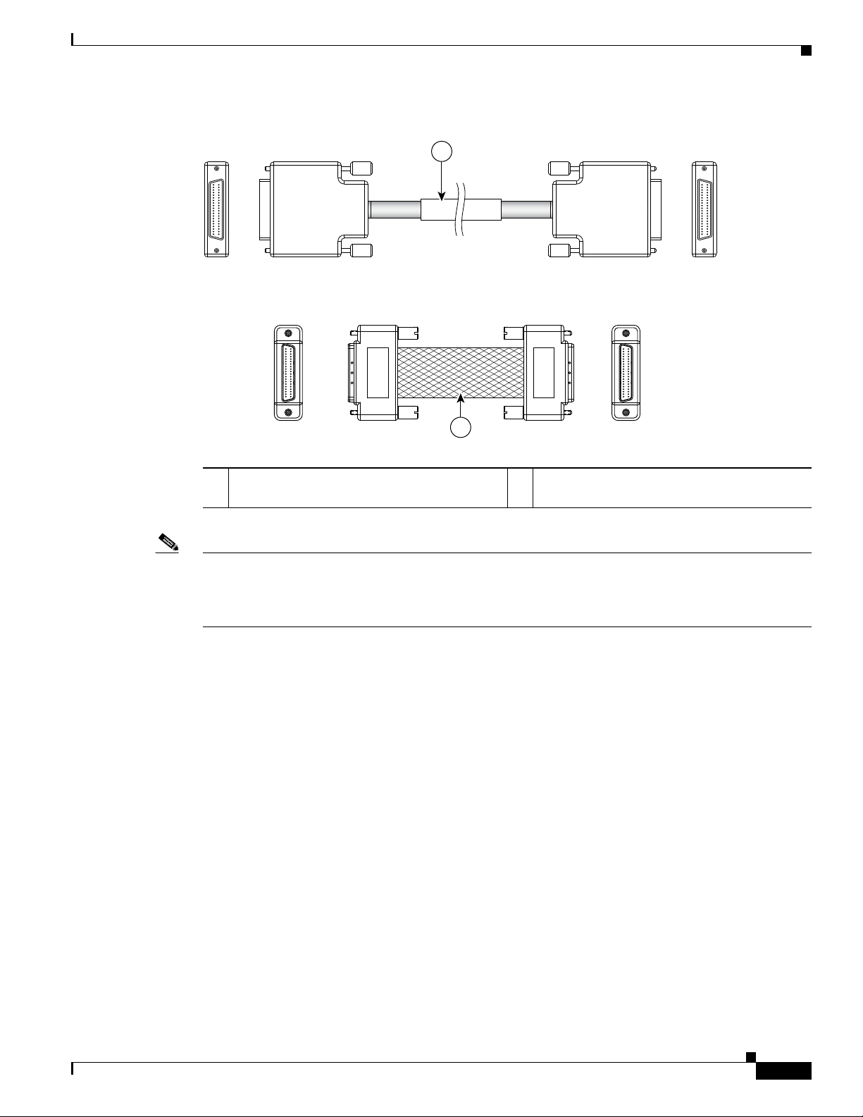
Chapter 2 Overview: Cisco XR 12000 Series Router Shared Port Adapters
129198
1
2
Figure 2-43 SPA Mate Cables
2-Port and 4-Port OC-48/STM-16 POS SPA Overview
1 Long length RPR mate cable for single port
RPR SPAs (CBL-RPR-OC48-L)
Note The RPR mate cable is necessary only when the SPA is to be used in RPR mode. It is not needed in POS
2 Short length RPR mate cable for single port
RPR SPAs (CAB-RPR-OC48-S)
mode. Support for the RPR feature is dependent on the platform soft ware release feature content. Verify
support for the RPR feature support by reviewing the relevant SPA datasheets or by contacting your
Cisco representative.
2-Port and 4-Port OC-48/STM-16 POS SPA Overview
The following sections describe the 2-Port and 4-Port OC-48/STM-16 POS SPA:
• 2-Port and 4-Port OC-48/STM-16 POS SPA LEDs, page 2-62
• 2-Port and 4-Port OC-48/STM-16 POS SPA Interface Specifications, page 2-63
• 2-Port and 4-Port OC-48/STM-16 POS SP A Cables, Optical Transceiver Modules, and Connectors,
page 2-63
OL-17438-04
Cisco XR 12000 Series Router SIP and SPA Hardware Installation Guide
2-61
Page 92

Chapter 2 Overview: Cisco XR 12000 Series Router Shared Port Adapters
STATUS
0
1
SPA-2XOC48-POS/RPR
138086
PTH
CAR
PRT
ACT
PTH
CAR
PRT
ACT
1 2
3 4 5
2-Port and 4-Port OC-48/STM-16 POS SPA Overview
2-Port and 4-Port OC-48/STM-16 POS SPA LEDs
The 2-Port and 4-Port OC-48/STM-16 POS SPA has f ive types of LEDs: four LEDs for each port on the
SPA and one STATUS LED, as shown in
Figure 2-44 2-Port OC-48 POS/RPR SPA Faceplate
1 PTH (Pass Through) LED 4 ACT (Active Loopback) LED
2 PRT (Protect) LED 5 STATUS LED
3 CAR (Carrier Alarm) LED
Figure 2-44.
Table 2-41 describes the 2-Port and 4-Port OC-48/STM-16 POS SPA LEDs.
Table 2-41 2-Port and 4-Port OC-48/STM-16 POS SPA LEDs
LED Label Color State Meaning
PTH Off Off Port is not in pass-through mode.
Green On Port is in pass-through mode.
CAR Off Off Port is not enabled by software.
Green On Port is enabled by software, and there is a valid
SONET signal without any alarms.
Amber On Port is enabled b y software, an d there is at least
one alarm.
Amber Flashing Port is enabled by software, and there is a side
mismatch.
PRT Off Off Port is not wrapped or steering.
Green On A node on the ring is wrapped.
Green Flashing A node on the ring is steering.
Amber On Port is locally wrapped.
Amber Flashing Port is locally steering.
ACT Off Off Port is not enabled by software.
Green On Port is enabled by software, and loopback is of f.
Amber On Port is enabled by software, and loopback is on.
2-62
Cisco XR 12000 Series Router SIP and SPA Hardware Installation Guide
OL-17438-04
Page 93

Chapter 2 Overview: Cisco XR 12000 Series Router Shared Port Adapters
/ / / /
/ /
TXRX
2-Port and 4-Port OC-48/STM-16 POS SPA Overview
Table 2-41 2-Port and 4-Port OC-48/STM-16 POS SPA LEDs (continued)
LED Label Color State Meaning
STATUS Off Off SPA power is off.
Green On SPA is ready and operational.
Amber On SPA power is on and good, and the SPA is being
configured.
2-Port and 4-Port OC-48/STM-16 POS SPA Interface Specifications
The physical layer interface for the 2-Port and 4-Port OC-48/STM-16 POS SPA is Optical Carrier-48
(OC-48), and provides SONET an d SDH netw ork connecti vity wi th a per -port bandwid th of 2.488 Gbps.
Each port on the 2-Port and 4-Port OC-48/STM-16 POS SPA has one duplex LC-type receptacle that
allows connection to single-mode optical fiber.
2-Port and 4-Port OC-48/STM-16 POS SPA Cables, Optical Transceiver Modules, and Connectors
Use single-mode (for intermediate-reach configurations) optical fiber cable to connect your router to a
network or to connect two OC-48-equipped routers back-to-back.
The 2-Port and 4-Port OC-48/STM-16 POS SPA supports the following types of optical transceiver
modules:
• Single-mode short-reach (SR) SFP module—SFP-OC48-SR OC48/STM16c
• Single-mode intermediate-reach (IR) SFP module—SFP-OC48-IR1 OC48/STM16c
• Single-mode long-reach (LR) SFP module—SFP-OC48-LR2 OC48/STM16c
Each port on the 2-Port and 4-Port OC-48/STM-16 POS SPA has one duplex LC-type receptacle. For
single-mode optical fiber connections, you can use either a duplex LC-type cable (see
two simplex LC-type cables, one for transmit (TX) and one for receive (RX).
Figure 2-45 LC-Type Cable
Figure 2-45) or
OL-17438-04
Cisco XR 12000 Series Router SIP and SPA Hardware Installation Guide
2-63
Page 94

2-Port and 4-Port OC-48/STM-16 POS SPA Overview
OC-48 Module Connections
Table 2-42 shows the OC-48 specifications for use with the 2-Port and 4-Port OC-48/STM-16 POS SP A.
Table 2-42 OC-48 Specifications
Specification Description
Wavelength OC-48 SR: 1266 nm to 1360 nm
Cabling distance (maximum) OC-48 SR: 2 km (1.2 miles)
Operating case temperature range OC-48 SR: 23 to 158 degrees F (–5 to 70 degrees C)
TX power OC-48 SR: –10 to –3 dBm
Receiver sensitivity (maximum) OC-48 SR: –18 dBm
RX over lo a d OC-48 SR: –3 dBm
Maximum receiver power damage OC-48 SR: +5 dBm
Chapter 2 Overview: Cisco XR 12000 Series Router Shared Port Adapters
OC-48 IR-1: 1260 nm to 1360 nm
OC-48 LR-2: 1500 nm to 1580 nm
OC-48 IR-1: 15 km (9.3 miles)
OC-48 LR-2: 80 km (49.7 miles)
OC-48 IR-1: 23 to 158 degrees F (–5 to 70 degrees C)
OC-48 LR-2: 23 to 158 degrees F (–5 to 70 degrees C)
OC-48 IR-1: –5 to 0 dBm
OC-48 LR-2: –2 to +3 dBm
OC-48 IR-1: –18 dBm
OC-48 LR-2: –28 dBm
OC-48 IR-1: 0 dBm
OC-48 LR-2: –9 dBm
OC-48 IR-1: +5 dBm
OC-48 LR-2: +5 dBm
Mate Interface Cables
The 2-Port and 4-Port OC-48/STM-16 POS S PA supports two mate interface configurations:
• Mate between two OC-192 SPAs in the same SIP
• Mate between two OC-192 SPAs in adjacent SIPs
Two SPAs are connected using a 40–pin connector copper mate cable. The length of the cables allow
only two possible connection scenarios, next slot horizontal and same slot vertical. This assumes that the
chassis is mounted vertically.
Cisco XR 12000 Series Router SIP and SPA Hardware Installation Guide
2-64
Figure 2-46 shows the mate cables used to connect the SPAs.
OL-17438-04
Page 95

Chapter 2 Overview: Cisco XR 12000 Series Router Shared Port Adapters
129198
1
2
Figure 2-46 SPA Mate Cables
2-Port OC-48 POS RPR SPA Overview
1 Long length RPR mate cable for single port
RPR SPAs (CBL-RPR-OC192-L)
2-Port OC-48 POS RPR SPA Overview
The following sections describe the 2-Port OC48-POS/RPR SPA:
• 2-Port OC48-POS/RPR SPA LEDs, page 2-65
• 2-Port OC48-POS/RPR SPA Interface Specifications, page 2-67
• 2-Port OC48-POS/RPR SPA Cables, Optical Transceiver Modules, and Connectors, page 2-67
2-Port OC48-POS/RPR SPA LEDs
The 2-Port OC48-POS/RPR SPA has five LEDs, as shown in Figure 2-47.
2 Short length RPR mate cable for single port
RPR SPAs (CAB-RPR-OC192-S)
OL-17438-04
Cisco XR 12000 Series Router SIP and SPA Hardware Installation Guide
2-65
Page 96

2-Port OC-48 POS RPR SPA Overview
STATUS
0
1
SPA-2XOC48-POS/RPR
138086
PTH
CAR
PRT
ACT
PTH
CAR
PRT
ACT
1 2
3 4 5
Figure 2-47 2-Port OC48-POS/RPR SPA Faceplate
1 PTH (Pass-Through) LED 4 ACT (Active Loopback) LED
2 PRT (Protect) LED 5 STATUS LED
3 CAR (Carrier/Alarm) LED
The 2-Port OC48-POS/RPR SPA LEDs are described in Table 2-43.
Table 2-43 2-Port OC48-POS/RPR SPA LEDs
Chapter 2 Overview: Cisco XR 12000 Series Router Shared Port Adapters
LED Label Color State Meaning
PTH Off Off Port is not in pass-through mode.
Amber On Port is in pass-through mode.
CAR Off Off Port is not enabled by software.
Green On Port is enabled by software, and there is a valid
SONET signal without any alarms.
Amber On Port is enabled by software, and there is at least
one alarm.
Amber Blinking Port is enabled by software, and there is a side
mismatch.
PRT Off Off Port is not in wrap mode or steer.
Green On A node on the ring is wrapped.
Green Blinking A node on the ring is steering pass-through
Amber On Port is locally wrapped
Amber Blinking Port is locally steering
ACT Off Off Port is not enabled by software.
Green On Port is enabled by software, loopback is off.
Amber On Port is enabled by software, loopback is on.
STATUS Off Off SPA power is off.
Green On SPA is ready and operational.
Amber On SPA power is on and good, and SPA is being
configured.
2-66
Cisco XR 12000 Series Router SIP and SPA Hardware Installation Guide
OL-17438-04
Page 97

Chapter 2 Overview: Cisco XR 12000 Series Router Shared Port Adapters
/ / / /
/ /
TXRX
Cisco XR12000 IPSec VPN SPA Overview
2-Port OC48-POS/RPR SPA Interface Specifications
The physical layer interface for the 2-Port OC48-POS/RPR SPA is Optical Carri er-48 (OC-48), and the
2-Port
OC48-POS/RPR SPA is designed to comply with POS specifications. The
2-Port
OC48-POS/RPR SPA provides two 2.488-Gbps network interfaces for all supported platforms.
2-Port OC48-POS/RPR SPA Cables, Optical Transceiver Modules, and Connectors
Use single-mode (for intermediate-confi gurations) optical fiber cable to connect your router to a network
or to connect two OC-48-equipped routers back-to-back.
The 2-Port OC48-POS/RPR SPA supports the following types of optical transceiver modules:
• Single-mode short-reach (SR) SFP module—SFP-OC48-SR
• Single-mode intermediate-reach (IR) SFP module —SFP-OC48-IR1
• Single-mode long-reach (LR) SFP module — SFP-OC48-LR2
Each port on the 2-Port OC48-POS/RPR SPA has one duplex LC-type receptacle. For single-mode
optical fiber connections, you can use either a duplex LC-type cable (see
LC-type cables, one for transmit (TX) and one for receive (RX).
Figure 2-48 Duplex Patch Cable with LC-Type Connectors
Cisco XR12000 IPSec VPN SPA Overview
The Cisco XR12000 IPSec VPN SPA (SPA) provides remote access and remote site VPN connectivity
for the Cisco XR 12000 Series Router.
The following features are supported:
• Site-to-Site communication over point-to-point IPSec/GRE tunnels
• Remote User Access over IPSec tunnels.
Figure 2-48) or two simplex
Any slot of the Cisco XR 12000 Series Router that contains a Cisco XR 12000 SIP-401, Cisco XR 12000
SIP-501, or a Cisco
mixture of the Cisco XR12000 IPSec VPN SPA with other interface SPA types on the same SIP card.
XR 12000 SIP-601 can support up to two Cisco XR12000 IPSec VPN SPAs, or any
OL-17438-04
Cisco XR 12000 Series Router SIP and SPA Hardware Installation Guide
2-67
Page 98

Cisco XR12000 IPSec VPN SPA Overview
SPA-IPSEC-2GVPN SERVICES SPA
STATUS
129498
1
Note that the Cisco XR12000 IPSec VPN SPA (SPA-IPSEC-2G-2) supported on the Cisco XR 12000
Series Router is a different form factor from the IPSec VPN SPA supported on the Cisco 7600 router
(SPA-IPSEC-2G-1).
Chapter 2 Overview: Cisco XR 12000 Series Router Shared Port Adapters
Warning
Attempting to install a SPA-IPSEC-2G-1 into a Cisco XR 12000 SIP-401, Cisco XR 12000 SIP-501, or a
XR 12000 SIP-601 will result in mounting rail damage. Only the Cisco XR12000 IPSec VPN SPA
Cisco
(SPA-IPSEC-2G-2) is supported on the Cisco XR 12000 Series Router.
The following sections describe the IPSec VPN SPA:
• IPSec VPN SPA L EDs, page 2-68
IPSec VPN SPA LEDs
The IPSec VPN SPA has one LED, as shown in Figure 2-49.
Figure 2-49 IPSec VPN SPA Faceplate
2-68
1 STATUS LED
The IPSec VPN SPA LED is described in Table 2-44.
Table 2-44 IPSec VPN SPA LED
LED Label Color State Meaning
STATUS Off Off SPA power is off.
Amber On SPA is on and good, and the SPA is being configured.
Green On SPA is ready and operational.
Caution The Cisco XR 12000 SIP-401, Cisco XR 12000 SIP-501, and Cisco XR 12000 SIP-601 do not support
the IPSec VPN SPA (SPA-IPSEC-2G). Installing a IPSec VPN SPA in these carrier cards could damage
the guide rails.
Cisco XR 12000 Series Router SIP and SPA Hardware Installation Guide
OL-17438-04
Page 99

Chapter 2 Overview: Cisco XR 12000 Series Router Shared Port Adapters
1-Port and 3-Port Clear Channel OC-3 ATM SPA Overview
1-Port and 3-Port Clear Channel OC-3 ATM SPA Overview
The 1-Port and 3-Port Clear Channel OC-3 ATM SPA is a single-height SPA that installs into one SIP
subslot. The Clear Channel OC-3 ATM SPA with small form-factor pluggable (SFP) optical transceiver
modules provides SONET and SDH network connectivity with a per-port bandwidth of 155.52 Mbps.
For more information about SPA bandwidth, see the “Bandwidth Oversubscription” section in this
chapter.
The following sections describe the 1-Port and 3-Port Clear Channel OC-3 ATM SPA:
• 1-Port and 3-Port Clear Channel OC-3 ATM SPA LEDs, page 2-69
• 1-Port and 3-Port Clear Channel OC-3 ATM SPA Interface Specifications, page 2-70
• 1-Port and 3-Port Clear Channel OC-3 ATM SPA Cables and Connectors, page 2-70
1-Port and 3-Port Clear Channel OC-3 ATM SPA LEDs
The 1-Port and 3-Port Clear Channel OC-3 ATM SPA has three types of LEDs. There are two LEDs for
each port on the SPA, and one STATUS LED.
Figure 2-50 shows an example of these LEDs on a 3-Port
Clear Channel OC-3 ATM SPA.
Figure 2-50 3-Port Clear Channel OC-3 ATM SPA Faceplate
31 2
C/A
A/L
Port 0
0
1
2
SPA-3XOC3-ATM-V2
Port 1
Port 2
STATUS
1 C/A (Carrier/Alarm) LED 3 STATUS LED
2 A/L (Active Loopback) LED
The 1-Port and 3-Port Clear Channel OC-3 ATM SPA LEDs are described in Table 2-45.
Table 2-45 1-Port and 3-Port Clear Channel OC-3 ATM SPA LEDs
LED Label Color State Meaning
C/A Off Off Port is not enabled by software.
Green On Port is enabled by software, and there is a valid SONET signal
without any alarms.
Amber On Port is enabled by software, and there is at least one alarm.
A/L Off Off Port is not enabled by software.
270697
OL-17438-04
Cisco XR 12000 Series Router SIP and SPA Hardware Installation Guide
2-69
Page 100
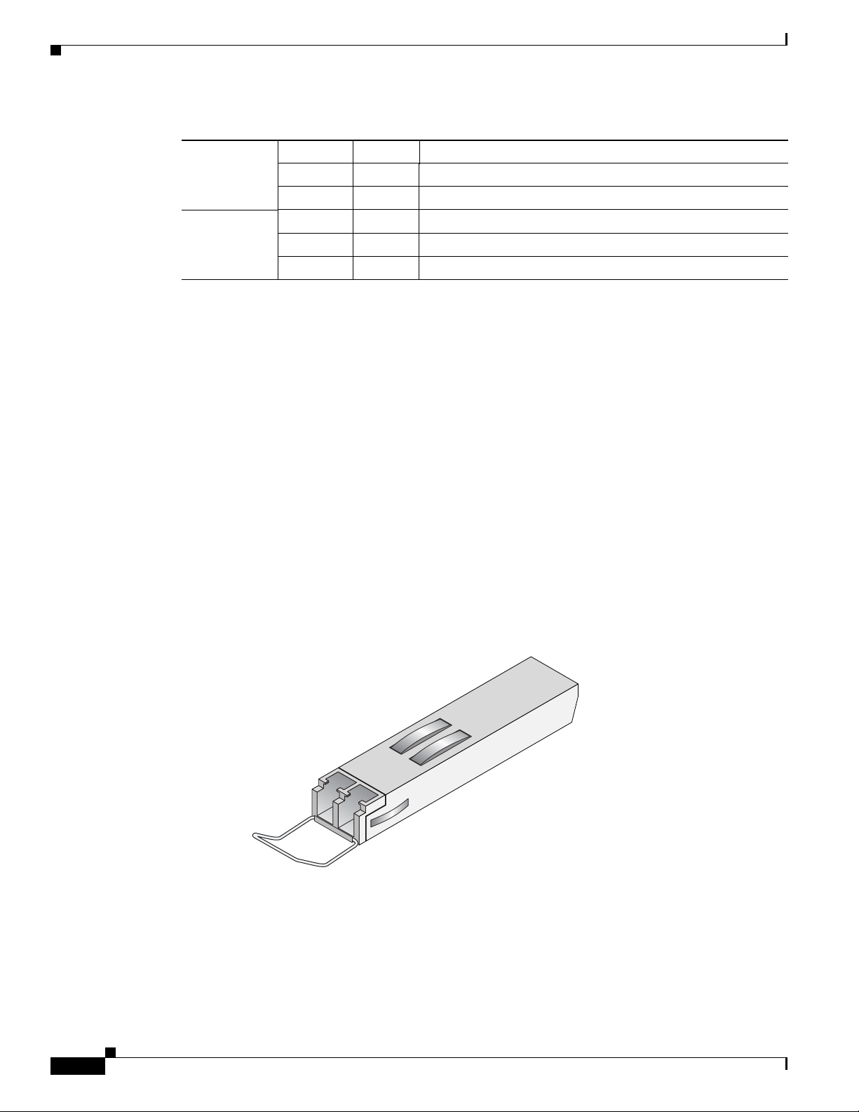
Chapter 2 Overview: Cisco XR 12000 Series Router Shared Port Adapters
127158
1-Port and 3-Port Clear Channel OC-3 ATM SPA Overview
Table 2-45 1-Port and 3-Port Clear Channel OC-3 ATM SPA LEDs (continued)
LED Label Color State Meaning
Green On Port is enabled by software, and loopback is off.
Amber On Port is enabled by software, and loopback is on.
STATUS Off Off SPA power is off.
Amber On SPA power is on and good, and SPA is being configured.
Green On SPA is ready and operational.
1-Port and 3-Port Clear Channel OC-3 ATM SPA Interface Specifications
The physical layer interface for the 1-Port and 3-Port Clear Channel OC-3 ATM SP A is Optical Carrier-3
(OC-3), and the data link layer is designed to comply with ATM specifications. The 1-Port and 3-Port
Clear Channel OC-3 ATM SPA provides up to one and three 155-Mbps OC-3 network interfaces,
respectively, for all supported platforms.
Each SPA port accepts an SFP module with a duplex LC-type receptacle that allows connection to
single-mode or multimode optical fiber.
1-Port and 3-Port Clear Channel OC-3 ATM SPA Cables and Connectors
The 1-Port and 3-Port Clear Channel OC-3 ATM SPA uses a small form-factor pluggable (SFP) optical
transceiver module inst alled in each port for SONET and SDH singl e-mode and multimode opt ical f iber
connection (see
Figure 2-51 SFP Optics Module
The SFP optical transceiver modules used with the 1-Port and 3-Port Clear Channel OC-3 ATM SPA
provide the
Figure 2-51).
following optical fiber options:
2-70
• Multimode—155-Mbps, OC-3 optical fiber (SONET STS-3c or SDH STM-1)
Use a multimode optical fiber that has a core/cladding diameter of 62.5/125 microns.
Cisco XR 12000 Series Router SIP and SPA Hardware Installation Guide
OL-17438-04
 Loading...