

Page 1

CHA PTER
Getting Started
This chapter describes the typical tasks you should complete to start using the Cisco 12000/10720
Router Manager application. See Figure 3-1 on page 3-2 for further details.
This chapter provides the following information:
• Cisco 12000/10720 Router Manager Workflow
• Starting Cisco EMF and Cisco 12000/10720 Router Manager
• Deployment
Cisco 12000/10720 Router Manager Workflow
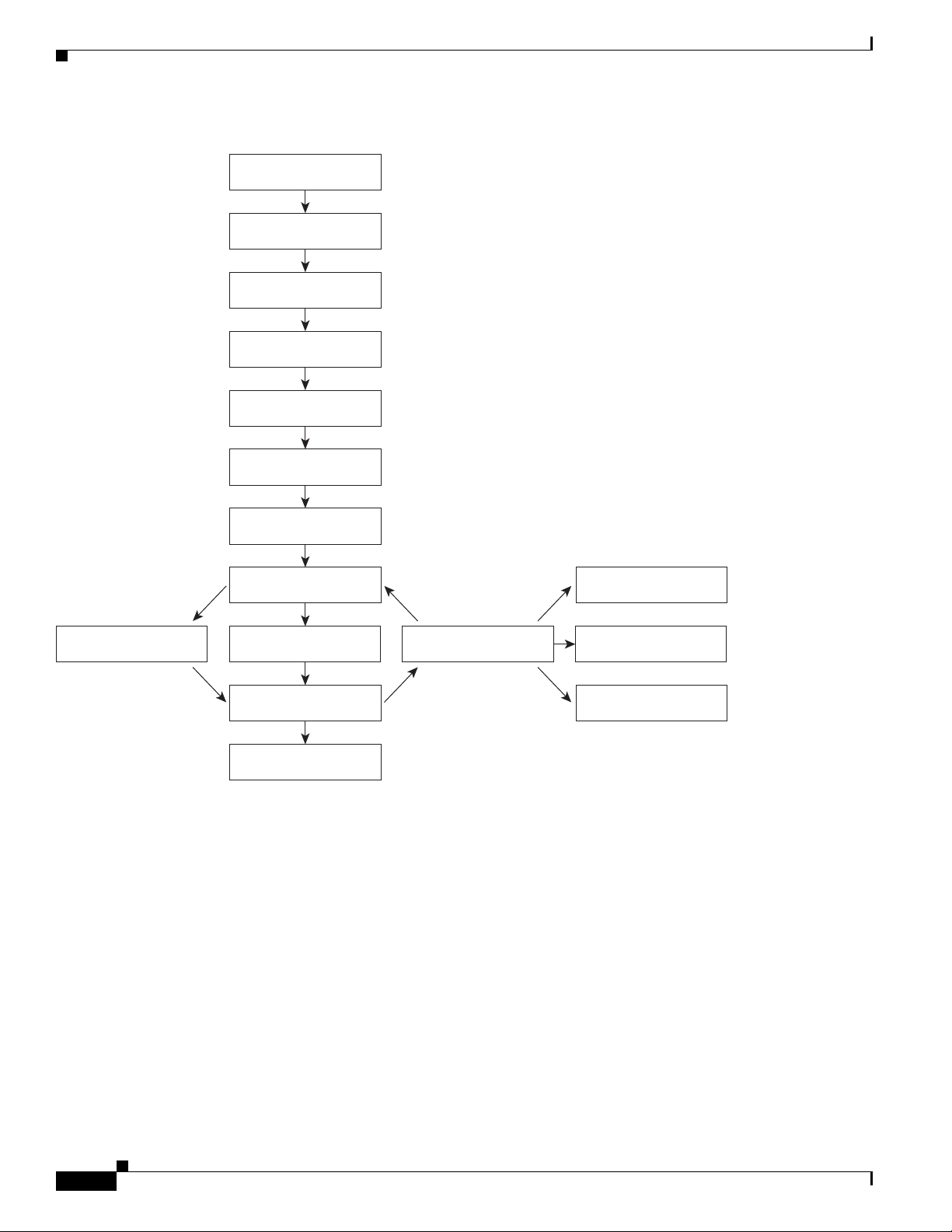
Figure 3-1 outlines the steps involved in installing, configuring and using the Cisco 12000/10720 Router
Manager application.
3
OL-4455-01
Cisco 12000/10700 v3.1.1 Router Manager User Guide
3-1
Page 2
Cisco 12000/10720 Router Manager Workflow
Figure 3-1 Workflow for Cisco 12000/10720 Router Manager
Install Cisco EMF
software
Install C12000/10720M
software
Start CEMF
Start a Cisco EMF
session
Deploy objects
Enter username
and password
Chapter 3 Getting Started
Chassis
Management
Perform Subchassis
discovery
Review deployment
and check for alarms
Module
Management
Fault
Management
Change
Management
Interface
Management
Layer 3 QoS
AT M
Connections
VLAN
Sub-interface
84835
3-2
Cisco 12000/10700 v3.1.1 Router Manager User Guide
OL-4455-01
Page 3

Chapter 3 Getting Started
Starting Cisco EMF and Cisco 12000/10720 Router Manager
Starting Cisco EMF and Cisco 12000/10720 Router Manager
The Cisco 12000/10720 Router Manager application is viewed through the Cisco Element Management
Framework (Cisco EMF). It is important to understand how Cisco EMF works before you use the Cisco
12000/10720 Router Manager application (refer to the Cisco Element Management Framework User
Guide for further details). Cisco 12000/10720 Router Manager automatically starts when you start a
Cisco EMF user session.
Note Each active Cisco EMF session uses a single Cisco EMF user license.
This section covers the following:
• Starting a Cisco EMF User Session
• Launchpad
• Quitting a Cisco EMF User Session
Starting a Cisco EMF User Session
Note Cisco EMF should already be running. When you try to invoke a Cisco EMF session, and
if you receive a message that Cisco EMF is not running, contact your system administrator,
or refer to the Cisco Element Management Framework User Guide for further details.
To start a Cisco EMF user session, proceed as follows:
Step 1 From the command line on the terminal window, enter <CEMF_ROOT>/bin/cemf session
Note <CEMF_ROOT> is the Cisco EMF installation root directory (for example,
/opt/CEMF).
OL-4455-01
Cisco 12000/10700 v3.1.1 Router Manager User Guide
3-3
Page 4
Starting Cisco EMF and Cisco 12000/10720 Router Manager
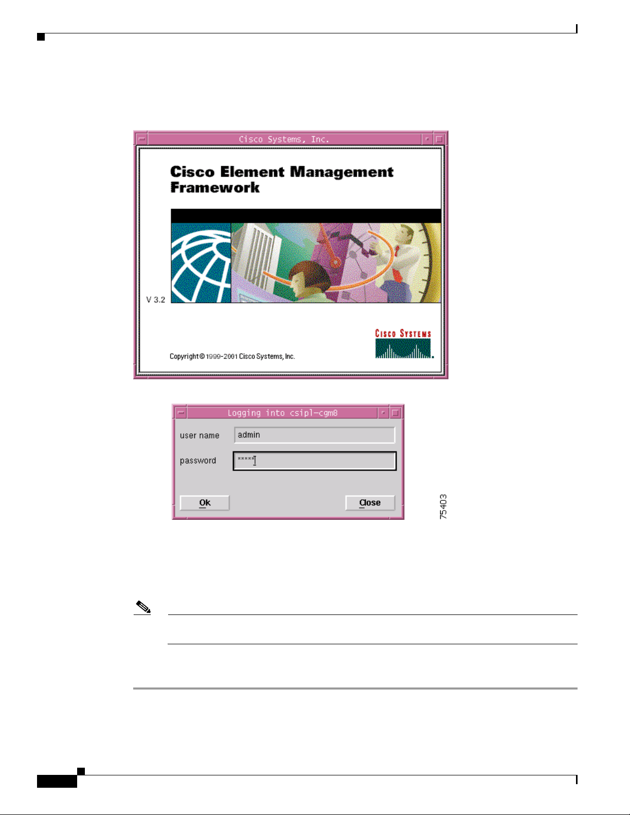
The Login window (see Figure 3-2) appears.
Figure 3-2 Login Window
Chapter 3 Getting Started
3-4
Step 2 Enter a valid user name and password.
Step 3 Click Ok to proceed.
When an unknown user name or password is entered, an error is displayed. Click Ok, then enter a valid
user name and password.
Note You have three attempts to enter a valid user name and password.After the third failed attempt
the session does not start and the Login window closes.
When a valid user name and the password are entered, the session starts and the Cisco EMF Launchpad
(see Figure 3-3) appears.
Cisco 12000/10700 v3.1.1 Router Manager User Guide
OL-4455-01
Page 5
Chapter 3 Getting Started
Launchpad
Starting Cisco EMF and Cisco 12000/10720 Router Manager
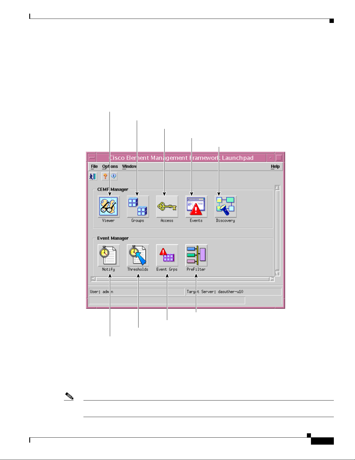
The icons displayed in the CEMF Manager and Event Manager panels on the Launchpad represent the
applications provided by this Cisco EMF installation. Extra icons may appear when additional packages
are installed. The icons (see Figure 3-3) represent the standard Cisco EMF tools.
Figure 3-3 Launchpad
Viewer icon - Launches MapViewer
Groups icon - Launches the Object Group Manager
Access icon - Launches Access Manager
Events icon - Launches the Query Editor and Event Browser
Discovery icon - Launches Auto Discovery
Launching an Application
From the Launchpad, click the desired icon. The application is launched. A “busy” icon and a message
in the status bar is displayed during launch. More than one instance of an application can be opened at
any time.
Note If an application is already open, it appears in the Windows list. Click Window and choose the
application you require from the drop down menu.
OL-4455-01
80864
PreFilter icon - Launches Pre Filtering Application
Event Grps icon - Launches Event Groups Application
Thresholds icon - Launches Thresholding Regimes Application
Notify icon - Launches Notification Profile Application
Cisco 12000/10700 v3.1.1 Router Manager User Guide
3-5
Page 6

Starting Cisco EMF and Cisco 12000/10720 Router Manager
Map Viewer (Viewer)
MapViewer allows complete flexibility in viewing, building, and monitoring your network using
graphical representations of network elements.
MapViewer is the primary entry point into the Cisco 12000/10720 Router Manager. When the
MapViewer application is launched, a window appears corresponding to the highlighted map icon in the
hierarchy pane. You can easily monitor the status of all network elements or abstractions of elements
contained within the network and you can launch any of the additional applications on the Launchpad.
Refer to the Cisco Element Management Framework User Guide for further details on the MapViewer
application.
Groups
Object Group Manager allows you to organize network elements into object groups. An object group is
a collection of objects which are related in some way. They may all be the same type of equipment or all
belong to the same customer.
Object groups can be built manually or by building a query. Some Cisco EMF subsystems may also build
object groups which may be visible and usable by the Cisco EMF user.
Refer to the Cisco Element Management Framework User Guide for further details on the Object Group
Manager application.
Chapter 3 Getting Started
Access
User Access Control allows system administrators the opportunity to control the features of their system
that can be accessed by various levels of personnel. This is important for secure network management.
Refer to the Cisco Element Management Framework User Guide for further details on the User Access
Control application.
Event Browser (Events)
One of the most important aspects of Network Service Management is the ability to identify faults and
other events on the network and to take action to resolve them quickly and efficiently. For example, there
may be a power supply fault in a chassis which would require an engineer to be sent out to rectify the
fault. This fault is critical to the running of the network and would need prompt attention.
In Cisco EMF, when a condition (fault) occurs on a managed object in the network, the system is notified
immediately. Notification is shown as an event and can be viewed with the Event Browser (when
configured to do so).
Refer to the Cisco Element Management Framework User Guide Release 3.2 for further details on the
Event Browser application.
Discovery
Discovery allow you to examine the network for IP and SNMP devices and create a managed object for
each new device discovered. Auto-discovery can be opened from the Launchpad window or from a pop
up menu available on selected objects.
3-6
Refer to the Cisco Element Management Framework User Guide Release 3.2 for further details on the
Auto-discovery application.
Cisco 12000/10700 v3.1.1 Router Manager User Guide
OL-4455-01
Page 7

Chapter 3 Getting Started
Notification Profiles
An important aspect of a monitoring system which captures and reacts to events on the network is when
and how a network operator is informed of these events. The Event Manager uses notifications for this.
For example, when the temperature of a line card rises 10 degrees above normal an e-mail might be sent
to the network operator warning of a potential problem and a minor event might be generated if the
temperature does not fall to within ten degrees of normal within twenty minutes.
Notification profiles are collections of notifications. Each notification profile has a name and description
and can be accessed by all Event Manager users. Each includes a list of notifications, and is run
following a trigger, which could be an event entering an event group, or a threshold breach in a
thresholding regime. For example, when the first event is received by an event group a notification
profile may be triggered which causes a sound to occur which alerts the operator. As well as audible
alerts, a notification could be set up to display on screen, or to trigger an external notification such as an
e-mail.
Refer to the Cisco Element Management Framework User Guide Release 3.2 for further details on the
Notification Profiles application.
Thresholding Regimes
Starting Cisco EMF and Cisco 12000/10720 Router Manager
Event Groups
A Thresholding Regime is a set of threshold conditions for specified object attributes which, when
breached, causes one or more notification profiles to be run. The Thresholding Regime defines which
attributes should be polled and on what period, and defines the thresholding conditions. The
Thresholding Regime specifies object groups which contain the objects whose attributes will be polled.
Refer to the Cisco Element Management Framework User Guide Release 3.2 for further details on the
Thresholding Regimes application.
Event Groups allows you to organize network elements into event groups, and also view the status of
these groups as scoreboards. Users can create, delete and modify event groups and scoreboards. Event
groups are available to all users.
Event groups can be any combination of objects derived from the managed object class. These groups
are set up using queries which can be configured to match your requirements. For example, you could
choose to monitor a particular device, specify a time period, and choose to look at events which are
warnings or critical. You define a query so that the event group only includes the events which meet the
criteria you define. As soon as the group is created it starts monitoring against the criteria specified in
the event query setup. Event groups created in the Event Groups application are persistent, they are not
cleared when the application is closed.
The Event Groups application also enables you to view the events associated with an event group in a
scoreboard format. This displays the overall status of the event group as a pie chart, with the associated
severity color coding. A scoreboard also shows the total number of events which have entered the event
group and the highest severity of the events in the group. An icon is displayed when a running
notification has been set up for the event group.
Event Groups is opened from the Launchpad.
OL-4455-01
Refer to the Cisco Element Management Framework User Guide Release 3.2 for further details on the
Event Groups application.
Cisco 12000/10700 v3.1.1 Router Manager User Guide
3-7
Page 8

Deployment
PreFilter
Event pre-filtering allows any event generated by the network which matches the criteria established in
the filter to be “filtered out”, and thus not saved into the database.
Pre-filtering offers you the capability to eliminate unwanted or undesired events from entering the
management system altogether. Pre-filtering is managed through the PreFilter application or from the
Event Browser. The PreFilter application is launched via the PreFilter icon on the Launchpad.
The PreFilter manager window displays, listing each of the pre-filters established, in the order in which
they are to be processed (from top to bottom).
Refer to the Cisco Element Management Framework User Guide Release 3.2 for further details on the
PreFilter application.
Quitting a Cisco EMF User Session
To quit the current Cisco EMF session, proceed as follows:
Step 1 Choose File > Quit. You see the question Do you wish to quit the Cisco EMF Manager System?.
Chapter 3 Getting Started
Step 2 Click Ye s to quit the session (all active applications are closed and the session terminates) or click No
Deployment
to return to the current Cisco EMF session.
The first step toward managing a Cisco 12000/10720 Router is to deploy or pre-deploy the physical
objects that you want to manage. Deploying a physical object creates a representative object in
Cisco EMF and as a result, makes the Cisco 12000/10720 Router Manager application aware of the
physical object’s presence.
Cisco 12000/10720 Router Manager objects can be discovered automatically or deployed manually. For
example, to deploy a chassis, you can use auto discovery or you can manually deploy the chassis. If you
wish to deploy objects under the chassis, you can use subchassis discovery or manually deploy each
object (interfaces are automatically created when you deploy each line card).
If all or most of your chassis objects are physically present and if you have a large amount of objects to
deploy, you might want to automate these processes by using auto discovery. For example, if Cisco
12000/10720 Router Manager is installed into an existing network of Cisco 12000/10720 Routers, auto
discovery can dramatically reduce the amount of operator input required. If you only want to deploy a
few objects or if many of your objects are not yet physically present, you might want to deploy manually.
Cisco 12000/10720 Router Manager objects can be manually pre-deployed before the hardware arrives
on-site. See “Pre-deployment” section on page 3-58 for further details.
The following supporting modules can be deployed using subchassis discovery only, no manual
deployment is available for these modules:
• AC or DC power supply card
3-8
• Fan tray module
• Blower module
Cisco 12000/10700 v3.1.1 Router Manager User Guide
OL-4455-01
Page 9

Chapter 3 Getting Started
Tip WRED (Weighted Random Early Detection) and CAR (Committed Access Rate) objects
Deployment
You can also deploy either of the following logical objects:
• SVC—See “Deploying an SVC Object” section on page 12-22
• PVC—See “Deploying a PVC Object” section on page 12-18
• VLAN Domain, VLAN and VLAN sub-interface—See “Deploying VLAN objects” section on
page 13-4
are not created using the deployment wizard. For details on creating these objects manually,
see Chapter 11, “Layer 3 QoS.”
The Deployment section covers the following areas:
• Deployment Process Outline
• Manually Deploying a Generic Site Object
• IP Auto Discovery of the Cisco Chassis
• Manually Deploying a Cisco 12000/10720 Chassis
• Commissioning and Subchassis Discovery
• Manually Deploying Modules—Includes deploying line cards for 12000 Series router chassis
and10720 chassis
• Pre-deployment
Deployment Process Outline
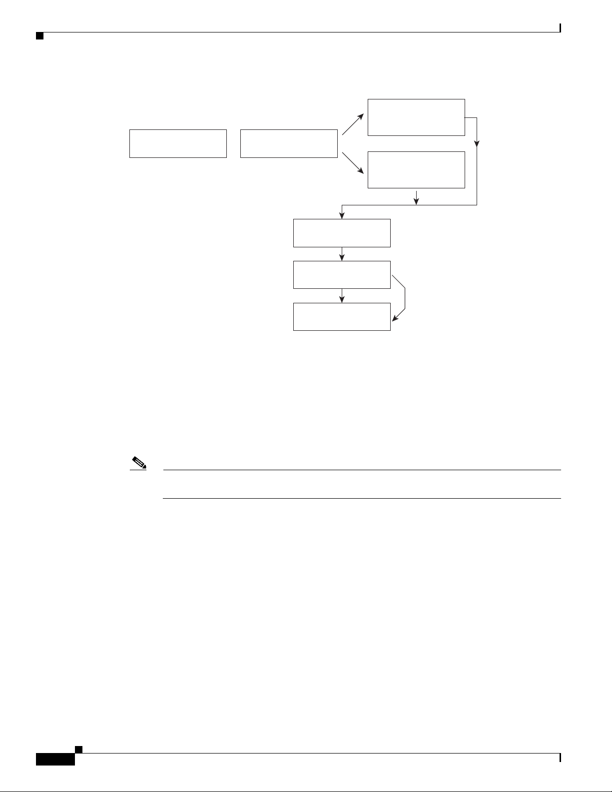
Producing a manageable Cisco 12000/10720 Router chassis in Cisco EMF is a three-stage process (see
Figure 3-4).
OL-4455-01
Cisco 12000/10700 v3.1.1 Router Manager User Guide
3-9
Page 10
Deployment
Figure 3-4 Deployment Process Workflow
Stage 1: Manually
deploy a generic object
Stage 2: Chassis
level deployment
Stage 3: Sub-chassis
Sub-chassis objects
OR
level deployment
Sub-chassis
Discovery
Optional
Manually deploy
Chapter 3 Getting Started
IP Auto-discovery of
Cisco 12000/10720
series chassis
Manual deployment of
the Cisco 12000/10720
series chassis
AND/OR
84836
The first deployment stage is to manually deploy a Generic (Site) object. A Site object can be looked
1.
upon as a container object where you can deploy further objects that represent the
Cisco 12000/10720 Router chassis, line cards and interfaces contained within the chassis. See
“Manually Deploying a Generic Site Object” section on page 3-10 for further details.
2. The second deployment stage is at the chassis level. The Cisco 12000/10720 Router chassis can be
auto discovered or manually deployed. See “IP Auto Discovery of the Cisco Chassis” section on
page 3-19 or the “Manually Deploying a Cisco 12000/10720 Chassis” section on page 3-20 for
further details.
Note You can pre-deploy objects (that is, manually predeploy objects) before the Cisco hardware
arrives on-site. See “Pre-deployment” section on page 3-58 for further details.
3. The third deployment stage is at subchassis level. This involves either subchassis discovery or
deploying subchassis objects (modules) manually. See “Commissioning and Subchassis Discovery”
section on page 3-26 or the “Manually Deploying Modules” section on page 3-30 for further details.
Manually Deploying a Generic Site Object
Generic objects are non-technology specific objects. When deploying a generic object, the information
you are prompted to provide differs according to the type and number of generic objects you are
deploying.
Table 3 -1 displays a list of generic objects that can be deployed using Cisco 12000/10720 Router
Manager.
3-10
Cisco 12000/10700 v3.1.1 Router Manager User Guide
OL-4455-01
Page 11
Chapter 3 Getting Started
Deployment
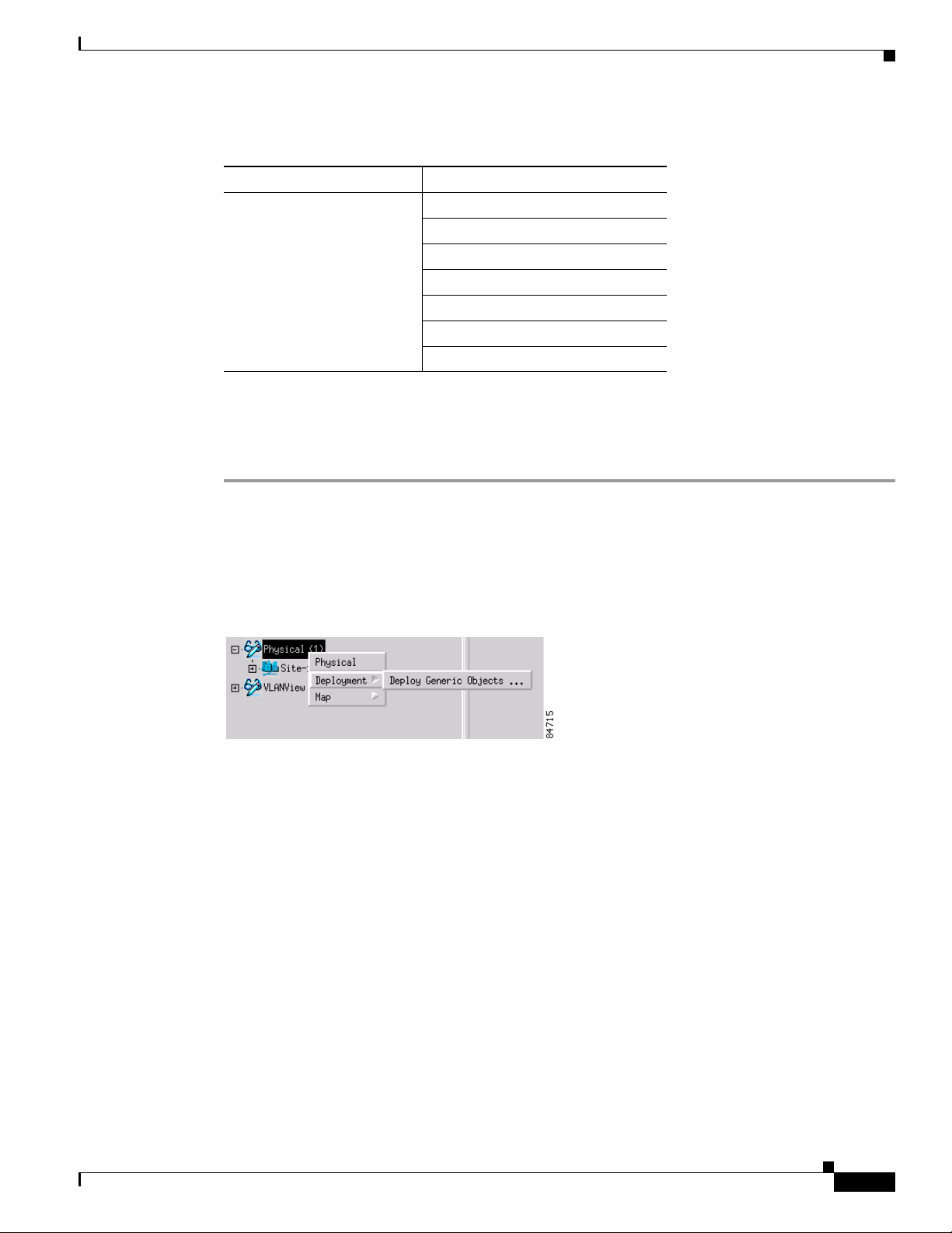
Table 3-1 Generic Object Deployment Templates
Object to be Deployed
Deployment Templates Available
Generic Bay
IP Device
Region
SNMP Agent
SNMP MIB-2 Agent
SNMP Proxied Device
Site
This section provided an example that shows how to deploy a Site object. The deployment process differs
slightly for other types of generic object.
To deploy a Generic (Site) object, proceed as follows:
Step 1 Place the cursor over a relevant object to determine the objects you can deploy from. In this example we
will deploy a Site object from the Physical view.
Step 2 Click and hold down the right mouse button.
Step 3 Choose Deployment>Deploy Generic Objects....
Figure 3-5 Deploying a Site Object
OL-4455-01
The Deployment Wizard - Templates window appears (see Figure 3-6) displaying a list of available
generic object deployment profiles. Deployment profiles are templates that prompt you for the
appropriate information required to deploy the selected object successfully.
Cisco 12000/10700 v3.1.1 Router Manager User Guide
3-11
Page 12
Deployment
Chapter 3 Getting Started
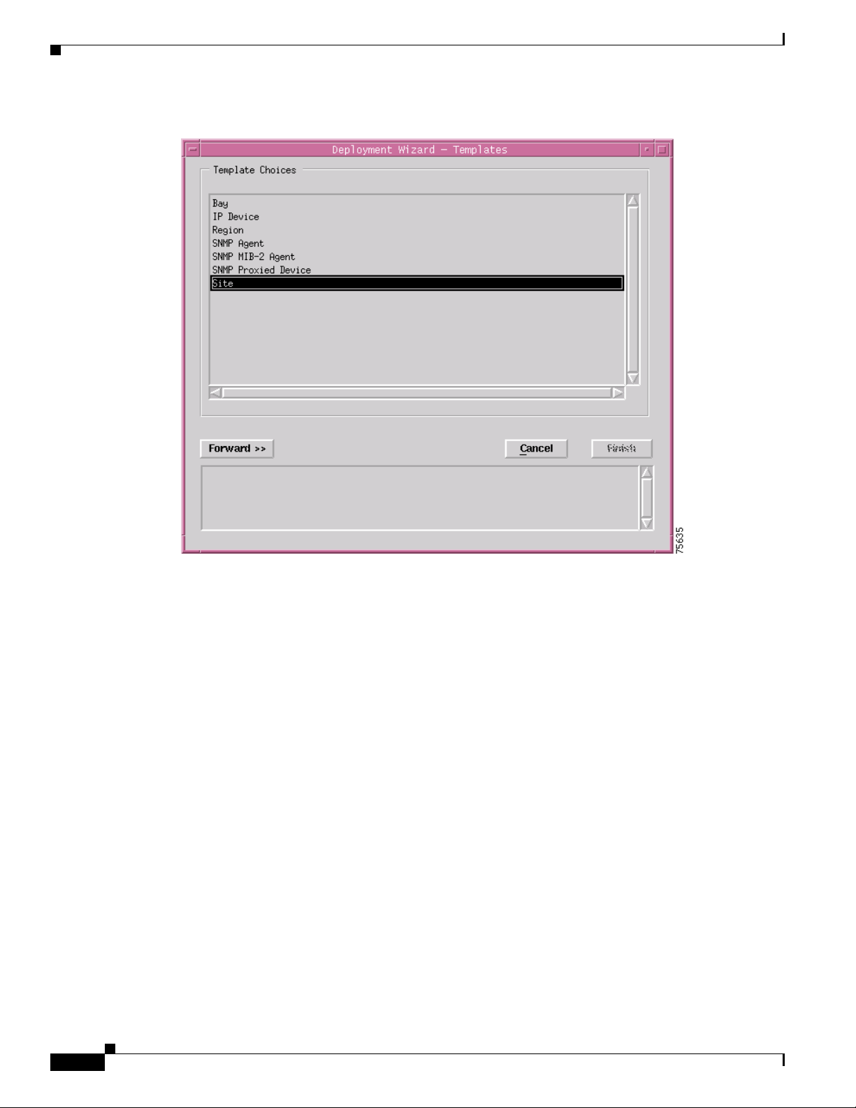
Figure 3-6 Deployment Wizard - Templates Window
Step 4
Select the generic object that you wish to deploy from the list supplied. In this example (shown in
Figure 3-6) shows the deployment profile for a Site object is selected. The Deployment Wizard steps
through a series of windows that prompt you for the information required to deploy the Site object.
Step 5 Click Forward.
3-12
Cisco 12000/10700 v3.1.1 Router Manager User Guide
OL-4455-01
Page 13
Chapter 3 Getting Started
Deployment
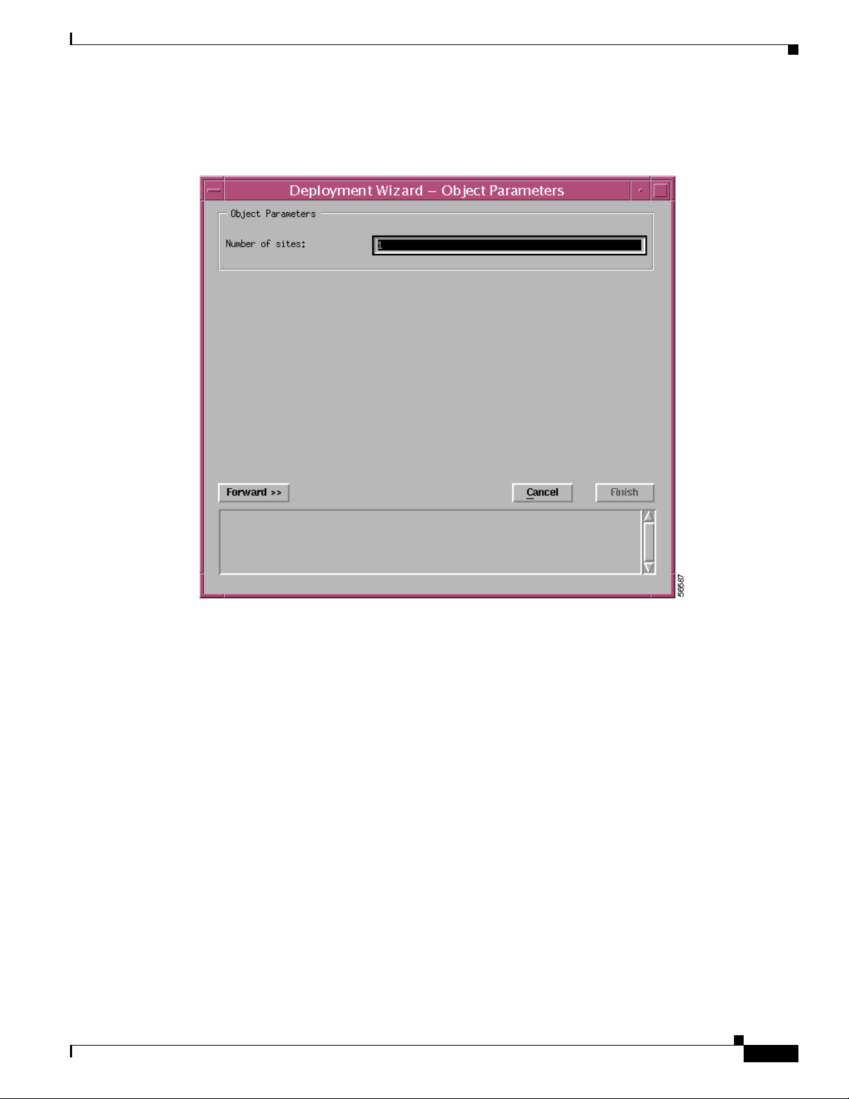
The Deployment Wizard - Object Parameters window appears (see Figure 3-7).
Figure 3-7 Deployment Wizard - Object Parameters Window (1 of 2)
Step 6 Enter the number of Sites required. A single site was entered in this example.
Step 7 Click Forward.
OL-4455-01
Cisco 12000/10700 v3.1.1 Router Manager User Guide
3-13
Page 14
Deployment
Chapter 3 Getting Started
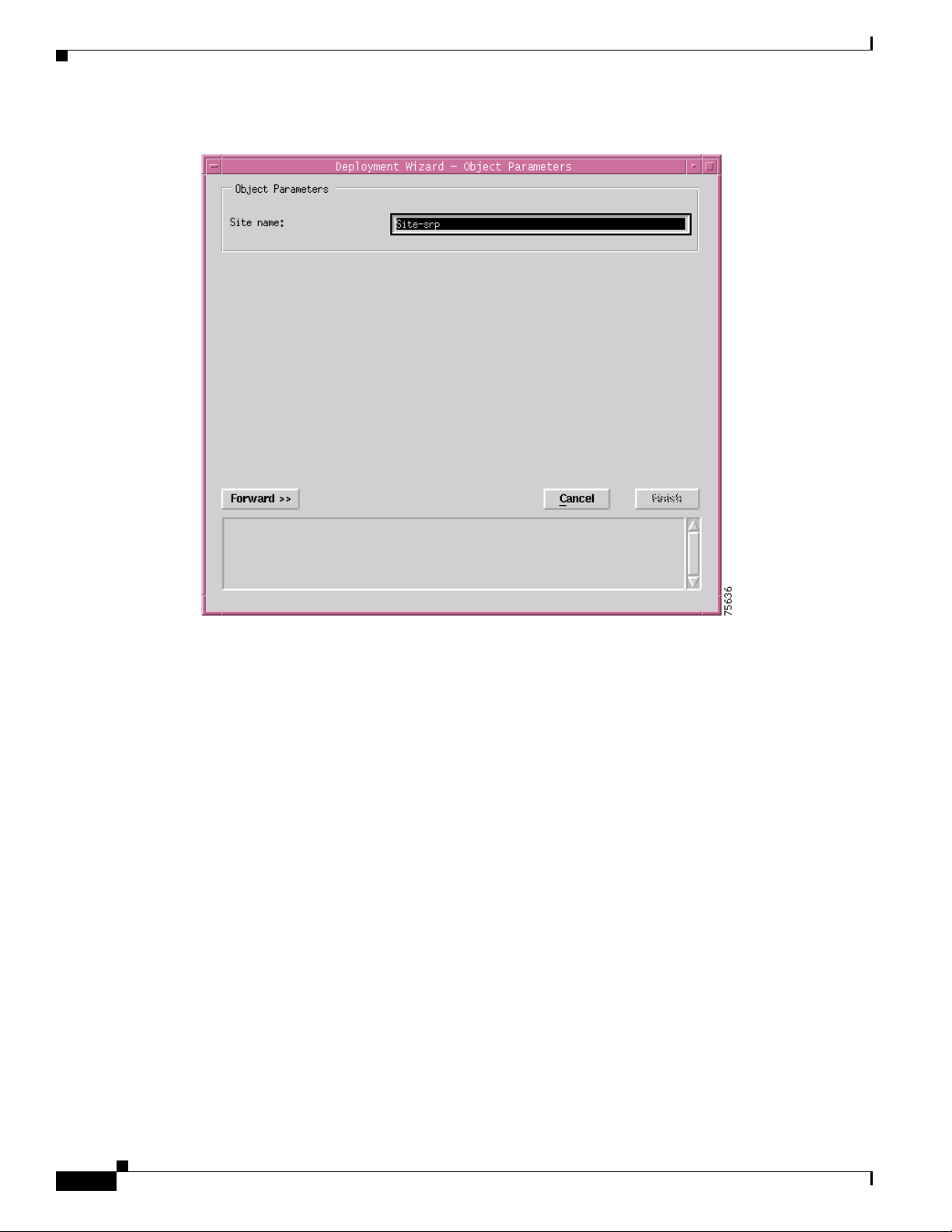
Figure 3-8 Deployment Wizard - Object Parameters Window (2 of 2)
Step 8
Step 9 Click Forward.
Enter a Site name. Each Site must have a unique name. In this example the site is called Site-srp.
3-14
Cisco 12000/10700 v3.1.1 Router Manager User Guide
OL-4455-01
Page 15
Chapter 3 Getting Started
Deployment
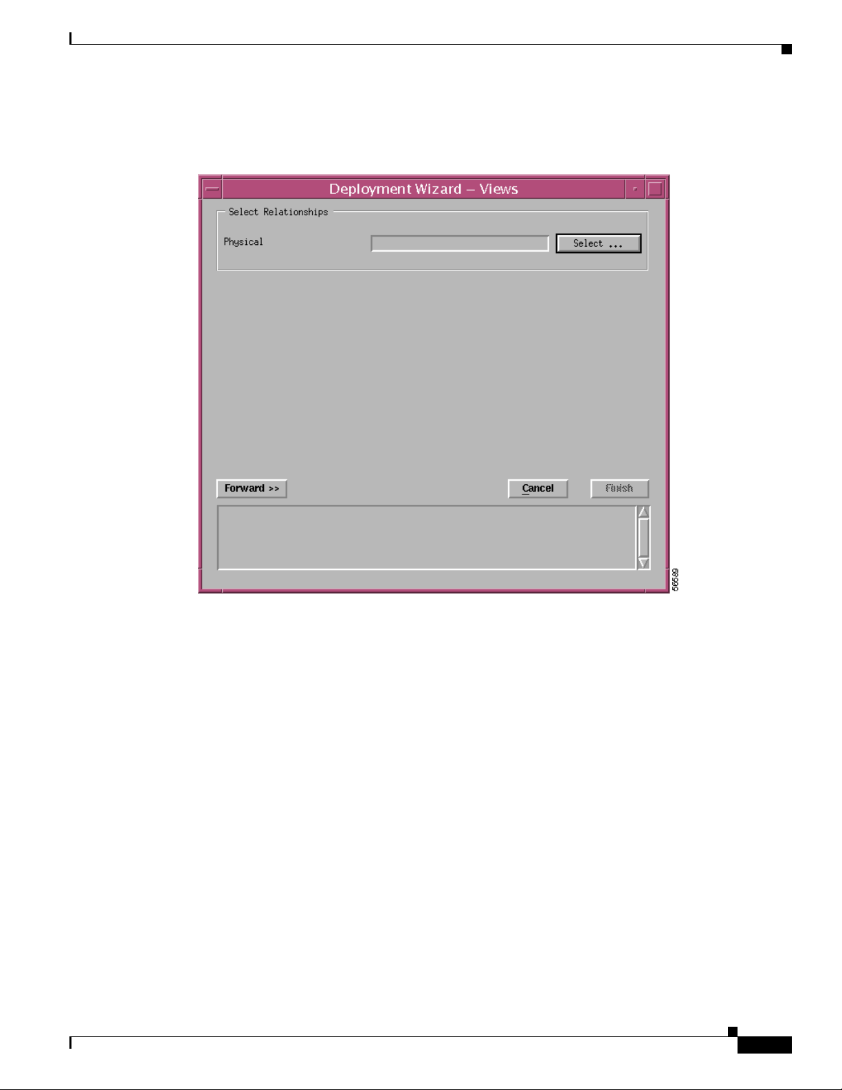
The Deployment Wizard - Views window appears.
Figure 3-9 Deployment Wizard—Views Window
Step 10
Click Select, to select a physical view.
OL-4455-01
Cisco 12000/10700 v3.1.1 Router Manager User Guide
3-15
Page 16
Deployment
Chapter 3 Getting Started
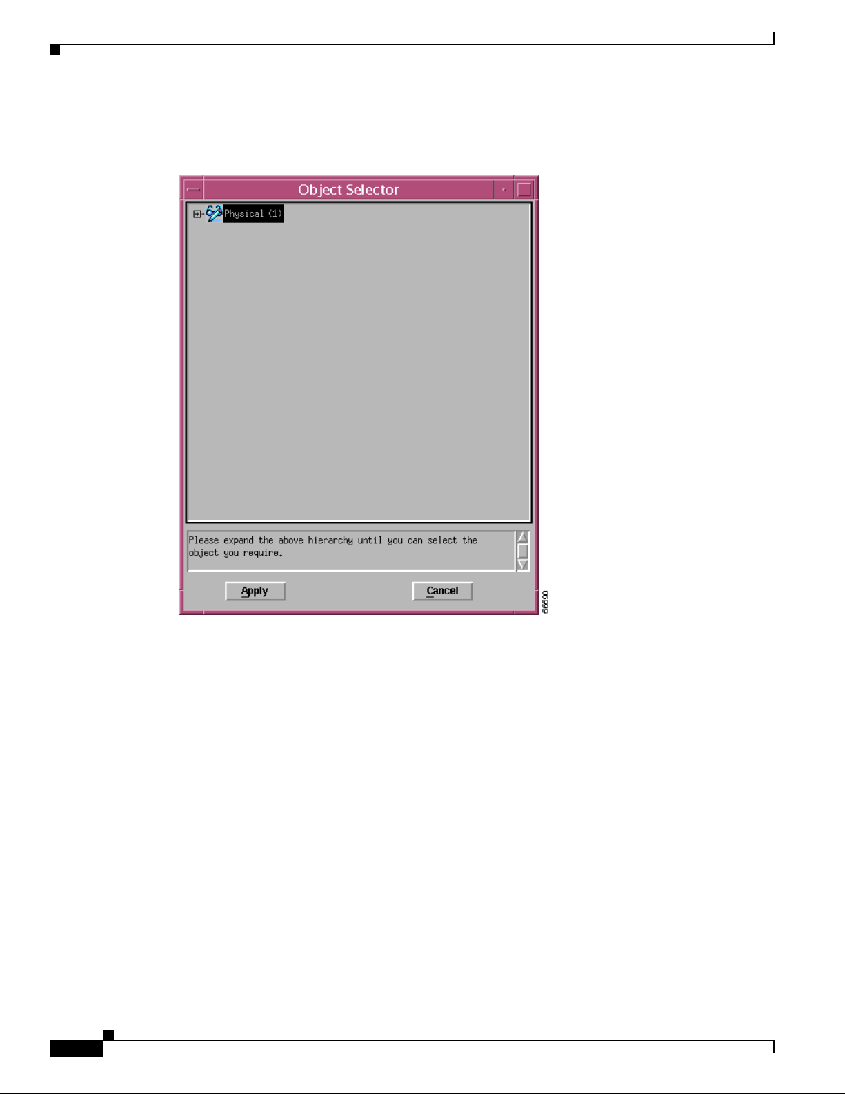
The Object Selector Window appears.
Figure 3-10 Object Selector
3-16
Step 11
Step 12 Click Apply. The Deployment Wizard - Views window re-appears with the selection displayed.
Cisco 12000/10700 v3.1.1 Router Manager User Guide
Select the object where you wish to place the Site object.
OL-4455-01
Page 17
Chapter 3 Getting Started
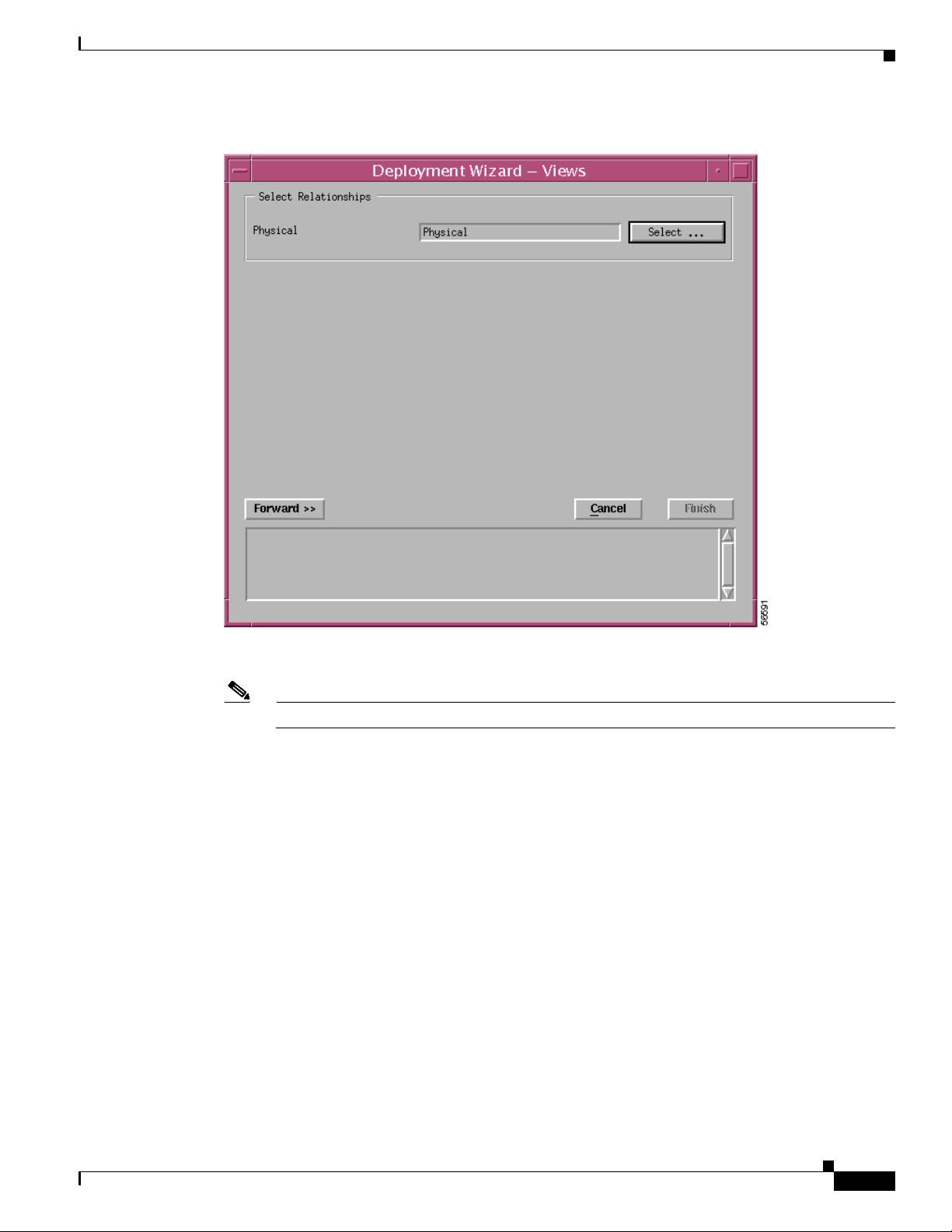
Deployment
Figure 3-11 Deployment Wizard—Views Window
Step 13 Click Forward.
Note You are prompted to repeat Steps 8 to 13 if you are deploying more than one Site.
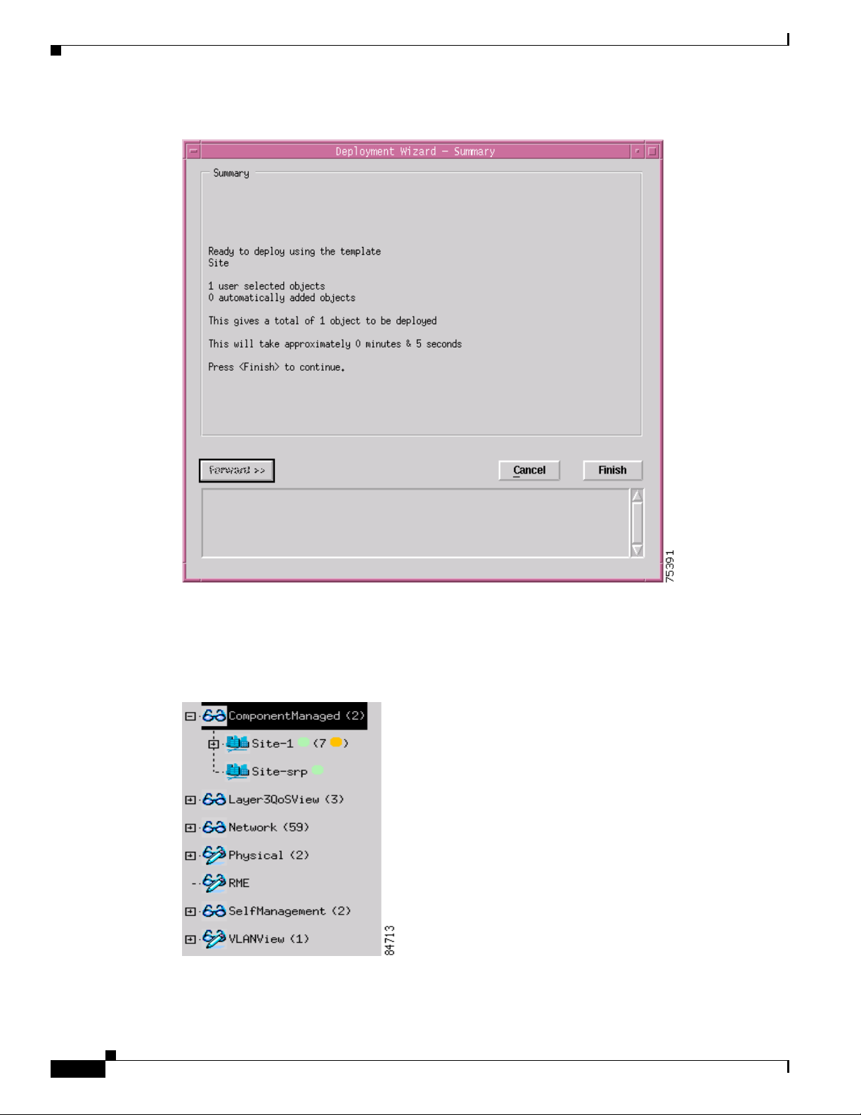
The Deployment - Wizard Summary window appears. The Summary window provides details of the
object you are about to deploy.
OL-4455-01
Cisco 12000/10700 v3.1.1 Router Manager User Guide
3-17
Page 18
Deployment
Chapter 3 Getting Started
Figure 3-12 Deployment Wizard—Summary Window
Step 14
Click Finish (when the Deployment Summary information is correct) to complete deployment and close
the Deployment Wizard - Summary window. The new Site object (that is, Site-srp) is created and
displayed in the Map Viewer window.
Figure 3-13 Example Showing the Newly Deployed Site-srp Object
3-18
Cisco 12000/10700 v3.1.1 Router Manager User Guide
OL-4455-01
Page 19

Chapter 3 Getting Started
Note This deployment procedure can be applied to the deployment of any of the generic objects
although all of the steps may not apply to the particular generic object that you are deploying.
IP Auto Discovery of the Cisco Chassis
Auto discovery is the application that discovers existing Cisco 12000/10720 Routers, saving time and
effort.
The auto discovery window can be opened from the Viewer or Discovery icon in the Launchpad. For
further information, refer to the Cisco Element Management Framework User Guide.
The Auto discovery application has three mechanisms for discovering chassis:
• IP—ICMP pings are used to find chassis in a given IP address range. This finds which IP devices
exist, but does not discover what kind of device they are.
• SNMP—SNMP get requests are used to find chassis in a given IP address range. Several SNMP
community strings can be used so that equipment with different community strings can be
discovered in the same discovery session. The SNMP information returned by devices is used to
work out what kind of device has been found.
• IP and SNMP—ICMP pings are used to find chassis and then SNMP requests are used to interrogate
the chassis to find out what kind of chassis they are. This is the default mechanism.
Auto discovery can discover chassis on more than one subnetwork using multi-hop discovery. It can be
scheduled to run at preset times (the Cisco Element Management Framework User Guide details how to
set the schedules).
Deployment
After the chassis is detected, an object representing the chassis is created and placed under the site from
which auto discovery was launched. A map of the chassis is also created, as shown in Figure 3-21 on
page 3-26.
Note If you wish to auto-discover a chassis that can be managed by Cisco 12000/10720 Router
Manager, then the Physical Path option must be enabled and an appropriate Physical Path
(terminated with a Site) must be selected. Provided this is done, the auto discovery
application will create a chassis below the selected Physical Path for each discovered
chassis.
OL-4455-01
Cisco 12000/10700 v3.1.1 Router Manager User Guide
3-19
Page 20

Deployment
Chapter 3 Getting Started
Figure 3-14 Example of Auto Discovery
Manually Deploying a Cisco 12000/10720 Chassis
Tip It is recommended that you ping the Cisco 12000/10720 Router you intend to deploy to ensure the device
can be contacted.
To deploy a chassis, proceed as follows:
Step 1 In the Map Viewer, right click on the site object under which you wish to deploy the chassis, then choose
Deployment>Cisco 12000/10720 Manager>12008 or 12012 or 12016 or 12404 or 12406 or 12410 or
12416 or 10720>Chassis. The Deployment Wizard appears.
3-20
Cisco 12000/10700 v3.1.1 Router Manager User Guide
OL-4455-01
Page 21

Chapter 3 Getting Started
Deployment
Figure 3-15 Deployment Wizard—Object Parameters (1 of 3)
Step 2 Enter the number of chassis objects you want to deploy. Click Forward.
OL-4455-01
Cisco 12000/10700 v3.1.1 Router Manager User Guide
3-21
Page 22

Deployment
Chapter 3 Getting Started
Figure 3-16 Deployment Wizard—Object Parameters Window (3 of 3)
Step 3
Enter the following information:
12000 Chassis Name—Type in a name (including prefix and suffix) for the chassis you are deploying.
A default prefix appears (for example, “12008”). You can delete this prefix and use your own, or you can
keep it and add your own suffix. This name must be unique.
IP Address—Type in the IP address for the chassis you are deploying.
Subnet Mask—The subnet mask for the IP address of the chassis.
SNMP Details—Type in the SNMP read and write communities, and select the SNMP version. The
default SNMP version is 2c.
Chassis Initial State—Specify the initial state for the chassis after deployment. The default initial state
of the chassis is decommission. When the user selects commission, the chassis is automatically
commissioned upon deployment.
Note Cisco 12000/10720 Router Manager allows the user to deploy a single chassis, more than once
provided they have unique subnet masks.
Step 4 Click Forward to continue. The Deployment Wizard-Views window appears.
3-22
Cisco 12000/10700 v3.1.1 Router Manager User Guide
OL-4455-01
Page 23

Chapter 3 Getting Started
Deployment
Figure 3-17 Deployment Wizard—Views
Step 5 Click on Select. The Object Selector window appears.
OL-4455-01
Cisco 12000/10700 v3.1.1 Router Manager User Guide
3-23
Page 24

Deployment
Chapter 3 Getting Started
Figure 3-18 Object Selector Window
Step 6 Choose the site under which you want to deploy the chassis. Click Apply. The Deployment
Wizard-Views window is displayed with the selected Site object.
Figure 3-19 Deployment Wizard—Views
3-24
Step 7
Cisco 12000/10700 v3.1.1 Router Manager User Guide
Click Forward. A Deployment Wizard Summary window is displayed.
OL-4455-01
Page 25

Chapter 3 Getting Started
Deployment
Figure 3-20 Deployment Wizard Summary
Step 8
The Deployment Summary details appear in the Deployment Summary Screen. If the Deployment
Summary information is correct, click Finish. If the Deployment Summary information is incorrect,
click Cancel to stop deployment.
Step 9 To proceed, you have two options:
• To perform subchassis discovery, see “Commissioning and Subchassis Discovery” section on
page 3-26
• If you wish to continue deploying individual modules, proceed to the “Manually Deploying
Modules” section on page 3-30.
OL-4455-01
Cisco 12000/10700 v3.1.1 Router Manager User Guide
3-25
Page 26

Deployment
Commissioning and Subchassis Discovery
After you deploy a chassis, the next step in creating a manageable system is to commission the chassis
(which begins the process of subchassis discovery). Figure 3-21 shows a Cisco 12008 chassis map in the
Physical view before subchassis discovery. Subchassis discovery discovers all physical objects (that is,
modules and interfaces) within the chassis and places them onto the chassis map.
Figure 3-21 Before Subchassis Discovery
Chapter 3 Getting Started
3-26
Line cards and interfaces located within the chassis are discovered at this time. Commissioning not only
discovers all the physical objects within the chassis, but also uploads the ATM connection objects (ATM
PVC objects only) and initiates heartbeat polling that allows alarms to be raised on the chassis and all
the physical objects within the chassis.
Cisco 12000/10700 v3.1.1 Router Manager User Guide
OL-4455-01
Page 27

Chapter 3 Getting Started
Because the chassis is the highest-level object, all objects under the chassis are commissioned as well
when you commission the chassis. One level down, if you commission a GRP, you commission all
physical objects underneath that level. If you commission a line card, you commission all interfaces on
that line card, and so on. However, note that before you can commission any module within a chassis,
the chassis object itself must be commissioned. This means that you must run subchassis discovery by
commissioning the chassis before you can commission or decommission any individual objects under
the chassis. If you do not want to actively manage all objects within the chassis, you can decommission
the objects you are not ready to manage after commissioning the chassis.
Tip If you are not ready to commission the chassis, you can manually deploy modules within
the chassis (for details, see “Manually Deploying Modules” section on page 3-30).
Modules can also be commissioned individually, provided the chassis is commissioned.
Commissioning a Chassis
When you commission a chassis, subchassis discovery begins automatically. Subchassis discovery
discovers and commissions all objects within the chassis. Commissioning automatically starts active
management (such as polling) on the chassis and all commissioned objects within the chassis.
To commission a chassis, proceed as follows:
Deployment
Step 1 It is recommended that the Cisco IOS Username and Passwords are set correctly before proceeding.
Right click on the Site object that contains the chassis you wish to commission, then choose Cisco
12000/10720 Manager>Configuration>Chassis>Configuration. The Chassis Configuration window
appears.
OL-4455-01
Cisco 12000/10700 v3.1.1 Router Manager User Guide
3-27
Page 28

Deployment
Chapter 3 Getting Started
Figure 3-22 Chassis Configuration Window
3-28
Step 2
Choose the Chassis you want to commission from the list box at left of the window. Cisco 12000/10720
Router Manager allows you to select and commission multiple chassis simultaneously.
Note To select a contiguous block of chassis, click on the first chassis; then, without releasing the
mouse button, drag to the last desired entry and release. A subsequent click anywhere on the
window deselects all previous selections. To extend a currently selected block of chassis, hold
the Shift key down and click on the entry at the end of the group to be added. To add a
non-contiguous entry to the selection group, hold down the Ctrl (Control) key and click on the
entry to be added. It is recommended to commission at the most 15 chassis at a time.
Step 3 Configure the parameters displayed on the Configuration and Additional Description tabs, as required.
Note See “Chassis Configuration” section on page 4-7 for detailed information on the Chassis
Configuration window.
Step 4 Click Commission (located in the Actions frame).
Cisco 12000/10700 v3.1.1 Router Manager User Guide
OL-4455-01
Page 29

Chapter 3 Getting Started
Deployment
The chassis and all objects contained within are commissioned. A status report appears in the
Commission Status area displaying whether the commission action succeeded or failed.
Figure 3-23 shows a Cisco 12008 chassis map in the Physical view after successful subchassis discovery.
Modules and interfaces are automatically deployed within the chassis and enter the commissioned state.
However, icons representing the physical objects appear in the Component Managed view.
Figure 3-23 After Subchassis Discovery
OL-4455-01
Note After commissioning a chassis you can configure and manage the chassis objects. See Chapter 4,
“Managing Chassis,” for further details.
Cisco 12000/10700 v3.1.1 Router Manager User Guide
3-29
Page 30

Deployment
Decommissioning a Chassis
Decommissioning a chassis, decommissions all the objects within the chassis, and active management
(such as polling) stops on the chassis and on all objects within the chassis.
To decommission a chassis, proceed as follows:
Step 1 Right click on the chassis you want to decommission, then choose Cisco 12000/10720
Manager>Configuration>Chassis>Configuration.
The Chassis Configuration window appears (see Figure 3-22).
Step 2 Choose the Chassis you want to decommission in the Chassis list box at left of the window.
Step 3 Click Decommission (located in the Actions area). The chassis and all objects contained within the
chassis are decommissioned. A status report appears in the Commission Status area, which shows
whether the action has succeeded or failed.
Object States
Chapter 3 Getting Started
After subchassis discovery all objects enter a specific state. See “Cisco 12000/10720 Router Manager
Object States” section on page 2-13 for details about object states.
Manually Deploying Modules
This section details the procedure to manually deploy modules using the Deployment Wizard. You can
manually deploy modules before they are physically present (for details, see “Pre-deployment” section
on page 3-58). In this scenario, you need to manually deploy modules, as a subchassis discovery will not
pick up their presence. You can also decommission these modules if you do not want active management
to be carried out on them.
Deployable modules include the following:
• GRPs
• Line cards (ATM, POS, Ethernet, DS-3, SRP or Modular Ethernet)
Tip Supporting modules, such as AC or DC power supply cards, fan tray modules, and blower
modules, can only be deployed through subchassis discovery. You cannot manually deploy
these modules.
Note Manual deployment of SRP Modules is currently not supported.
3-30
Cisco 12000/10700 v3.1.1 Router Manager User Guide
OL-4455-01
Page 31

Chapter 3 Getting Started
User Named vs. Auto Named Module Deployment
When you deploy a module, you have two initial options:
• To deploy an auto-named module
• To deploy a user-named module
The user-named option allows you to name the module as you like. For example, if you have a specific
naming scheme you want to use, then select the user-named option.
The auto-named option assigns an auto-generated name to the module, with the slot number appended
to the name. For example, if you deployed an auto-named ATM line card in slot 5, the name given would
be “A5.” This option is most useful when you have numerous line cards of the same type to deploy.
However, the line cards must be deployed in sequence within the slots. For example, if you wanted to
deploy five ATM line cards in slots 1 to 5, then the auto-named option would be ideal.
Manually Deploying a GRP Card
Each chassis must have at least one GRP card deployed. A second optional GRP card can be deployed
for the purpose of redundancy.
Deployment
Note This feature is not applicable to the 10720 chassis
To deploy a GRP, proceed as follows:
Step 1 Right-click on the slot within the chassis where you want the GRP to be deployed, then choose
Deployment>Cisco 12000/10720 Manager>Module>RP>GRP. The Deployment Wizard appears.
OL-4455-01
Cisco 12000/10700 v3.1.1 Router Manager User Guide
3-31
Page 32

Deployment
Chapter 3 Getting Started
Figure 3-24 Deployment Wizard—Templates
Step 2
Choose one of the Template Choices from the list displayed (either auto-named or user-named
deployment). Ensure that your choice is highlighted before continuing. See “User Named vs. Auto
Named Module Deployment” section on page 3-31 for further information on auto vs. user named
deployment.
Step 3 Click Forward. The Deployment Wizard - Object Parameters window appears.
3-32
Cisco 12000/10700 v3.1.1 Router Manager User Guide
OL-4455-01
Page 33

Chapter 3 Getting Started
Deployment
Figure 3-25 Deployment Wizard—Object Parameters
Step 4
Enter the Number of GRP objects you wish to deploy. Enter in the slot number where you want the GRP
to be deployed. If you are deploying two GRPs, the primary GRP must be placed in a slot with a lower
number than the secondary GRP.
Caution If you deploy a module in a slot that is already occupied, deployment will fail at the Finish point. Also
deployment fails, if a module is deployed with a name that already exists in the EM.
Step 5 Click Forward. The Deployment Wizard - Views window appears. Two Cisco 12000/10720 Router
Manager views are displayed at the left side of the Deployment Wizard - Views window (that is, Physical
and ComponentManaged).
OL-4455-01
Cisco 12000/10700 v3.1.1 Router Manager User Guide
3-33
Page 34

Deployment
Chapter 3 Getting Started
Figure 3-26 Deployment Wizard—Views
Step 6 Click Select. The Object Selector window appears.
3-34
Cisco 12000/10700 v3.1.1 Router Manager User Guide
OL-4455-01
Page 35

Chapter 3 Getting Started
Deployment
Figure 3-27 Object Selector Window
Step 7 Navigate through the hierarchy and choose the chassis that the GRP will be deployed within. Grayed out
objects are not available for selection.
Step 8 Click Apply. The Deployment Wizard - Views window re-appears with the location where the object will
be placed.
OL-4455-01
Cisco 12000/10700 v3.1.1 Router Manager User Guide
3-35
Page 36

Deployment
Chapter 3 Getting Started
Figure 3-28 Deployment Wizard—Views
Step 9
Step 10 Click Forward. The Deployment Wizard-Summary window appears.
Repeat Steps 6 to 8 to place the chassis object in each of the Physical and ComponentManaged views.
Note You are prompted to repeat steps 6 to 8 if you are deploying more than one GRP card.
3-36
Cisco 12000/10700 v3.1.1 Router Manager User Guide
OL-4455-01
Page 37

Chapter 3 Getting Started
Deployment
Figure 3-29 Deployment Wizard—Summary
Step 11 The deployment summary details appear in the Deployment Summary window. If the deployment
summary information is correct, click Finish. If the deployment summary information is incorrect, click
Cancel to stop deployment.
Note Two objects are deployed when deploying each GRP card: the GRP module object itself, and the
Ethernet interface object, representing the Ethernet interface on the GRP.
OL-4455-01
Cisco 12000/10700 v3.1.1 Router Manager User Guide
3-37
Page 38

Chapter 3 Getting Started
Deployment
Manually Deploying Line Cards
The Cisco 12000 Series Router chassis supports six types of technology specific line cards (ATM, POS,
Ethernet, SRP, DS-3 and Modular Ethernet). See Ta bl e 3-2 to Tab le 3-7 for further details.
Line Cards Supported by Cisco 12000 Series Routers
Table 3 -2 displays a list of the ATM line cards supported by Cisco 12000 Series Routers.
Table 3-2 ATM Line Cards Supported by Cisco 12000 Series Routers
Cisco 12000/10720 Router
Card Type
atm-qoc3-sm ATM > OC-3 4 > SM 4 Port OC3 ATM Single Mode (SM) Line Card
atm-qoc3-mm ATM > OC-3 4 > MM 4 Port OC3 ATM Multi Mode (MM) Line Card
gsr-en-8oc3 ATM > OC-3-8 > SM GSR enhanced 8 port OC3c/STM-1 ATM Line Card
sr-atm-en-8oc3-mm ATM > OC-3-8 > MM GSR enhanced 8 port OC3c/STM-1 Multimode ATM Line
atm-oc12-sm ATM > OC-12 1 > SM Single Port OC-12 Single Mode (SM) Line Card
atm-oc12-mm ATM > OC-12 1 > MM Single Port OC-12 Multi Mode (MM) Line Card
gsr-qoc12-sm ATM > OC-12 4> SM 4 port OC12 ATM Single Mode (SM) Line Card
gsr-qoc12-mm ATM > OC-12 4 > MM 4 port OC12 ATM Multi Mode (MM) Line Card
gsr-e48-atm-4oc12-mm-sr-sc cannot be manually deployed GSR Edge Engine 48, ATM, 4 port OC12/STM4Multi
gsr-e48-atm-4oc12-sm-ir-sc cannot be manually deployed GSR Edge Engine 48, ATM, 4 ports OC12/STM4 Single
Manager Menu Option Card Description
Card
Mode Short Reach Line Card
Mode Intermediate Reach Line Card
Table 3 -3 displays a list of the POS line cards supported by Cisco 12000 Series Routers.
Table 3-3 POS Line Cards Supported by Cisco 12000 Series Routers
POS
Cisco 12000/10720 Router Manager
Card Type
Menu Option Card Description
pos-qoc3-sm POS > OC-3 4 > E4 SM 4 Port Packet Over SONET OC-3c/SM Single
Mode Line Card
pos-qoc3-sm-l POS > OC-3 4 > E4 SM-LR 4 Port Packet Over SONET OC-3c/STM-1 Single
Mode Long Reach Line Card
pos-qoc3-mm POS > OC-3 4 > E4 MM 4 Port Packet Over SONET OC-3c/MM Multi
Mode Line Card
gsr-e48-pos-4oc3-mm-sr-mtrj POS > OC-3 4 > E4+ MM-SR 4 Port POS OC 48 Multi Mode Short Reach Line
Card
gsr-e48-pos-4oc3-sm-lr-lc POS > OC-3 4 > E4+ SM-LR 4 Port POS OC 48 Single Mode long Reach Line
Card
gsr-e48-pos-4oc3-sm-ir-lc POS > OC-3 4 > E4+ >SM-IR 4 Port POS OC 48 Single Mode Intermediate
Reach Line Card
Cisco 12000/10700 v3.1.1 Router Manager User Guide
3-38
OL-4455-01
Page 39

Chapter 3 Getting Started
Deployment
Table 3-3 POS Line Cards Supported by Cisco 12000 Series Routers (continued)
POS
Cisco 12000/10720 Router Manager
Card Type
pos-8oc3-mm POS > OC-3 8 Port > E4 MM 8 Port OC3 Multimode POS
pos-8oc3-ir POS > OC-3 8 Port > E4 SM 8 Port OC3 SM Intermediate Reach POS
pos-8oc3-lr POS > OC-3 8 Port > E4 SM-LR 8 port OC3 SM Long Reach POS
gsr-e48-pos-8oc3-mm-sr-mtrj POS > OC-3 8 Port > E4+ MM-SR 8 Port POS OC 3 multi MOde Short Reach Line
gsr-e48-pos-8oc3-sm-ir-lc POS > OC-3 8 Port > E4+ SM-IR 8 Port POS OC 3 Single Mode Intermediate Reach
pos-oc12-sm POS > OC-12 1 Port > SM 1 Port Packet Over SONET OC-12 Single Mode
pos-oc12-mm POS > OC-12 1 Port > MM 1 Port Packet Over SONET OC-12 Multi Mode
pos-qoc12-sm-lr POS > OC-12 4 Port > SM 4 Port (Quad) OC-12 POS Card, Single Mode,
pos-qoc12-mm-sr POS > OC-12 4 Port > MM 4 port (Quad) OC-12 POS Card, Single Mode,
pos-en-qoc12-sr POS > Enhanced OC-12 4 Port > MM Enhanced 4 Port OC-12 Short Reach Line Card
pos-en-qoc12-ir cannot be manually deployed Enhanced 4 port OC-12 Intermediate Reach Line
pos-oc48-sm-lr-fc POS > OC-48 > LR-FC 1 Port Packet Over Sonet OC-48, Single Mode,
pos-oc48-sm-lr-sc POS > OC-48 > LR-SC 1 Port Packet Over Sonet OC-48, Single Mode,
pos-oc48-sm-sr-fc POS > OC-48 > SR-FC 1 Port Packet Over SONET OC-48c/STM-16
pos-oc48-sm-sr-sc POS > OC-48 > SR-SC 1 Port Packet Over Sonet OC-48, Single Mode,
pos-en-oc48-lr-fc POS > Enhanced OC-48 > LR-FC Enhanced OC-48 Long Reach FC Connector Line
pos-en-oc48-lr-sc POS > Enhanced OC-48 > LR-SC Enhanced OC-48 Long Reach SC Connector Line
pos-en-oc48-sr-fc POS > Enhanced OC-48 > SR-FC Enhanced OC-48 Short Reach FC Connector Line
pos-en-oc48-sr-sc POS > Enhanced OC-48 > SR-SC Enhanced OC-48 Short Reach SC Connector Line
pos-en-qoc48-sm-sr-sc POS > Enhanced OC-48 4 > E4
pos-en-qoc48-sm-sr-fc POS > Enhanced OC-48 4 > E4
Menu Option Card Description
Card
Line Card
(SM) Line Card
(MM) Line Card
Long Reach
Short Reach
Card
Long Reach, FC Connector Card
Long Reach, SC Connector Card
Single Mode Short Reach with FC Connector
Short Reach, SC Connector Card
Card
Card
Card
Card
4 Port (Quad) Enhanced OC-48 Short Reach SC
SR-SC
Connector Line Card
4 Port (Quad) Enhanced OC-48 Short Reach FC
SR-FC
Connector Line Card
OL-4455-01
Cisco 12000/10700 v3.1.1 Router Manager User Guide
3-39
Page 40

Chapter 3 Getting Started
Deployment
Table 3-3 POS Line Cards Supported by Cisco 12000 Series Routers (continued)
POS
Cisco 12000/10720 Router Manager
Card Type
pos-en-qoc48-sm-lr-sc POS > Enhanced OC-48 4 > E4
pos-en-qoc48-sm-lr-fc POS > Enhanced OC-48 4 > E4
gsr-e-qoc48-sm-sr-sc POS > Enhanced OC-48 4 > E4+
gsr-e-qoc48-sm-sr-fc POS > Enhanced OC-48 4 > E4+
gsr-e-qoc48-sm-lr-sc POS > Enhanced OC-48 4 > E4+
gsr-e-qoc48-sm-lr-fc POS > Enhanced OC-48 4 > E4+
pos-oc192-sm-sr-sc POS > OC-192 1 > E4 SR-SC OC-192 Short Reach SC Connector Line Card
Menu Option Card Description
4 Port (Quad) Enhanced OC-48 Long Reach SC
LR-SC
Connector Line Card
4 Port (Quad) Enhanced OC-48 Long Reach FC
LR-FC
Connector Line Card
4 Port Enhanced OC 48 Short Reach SC
SR-SC
Connector Line Card
4 Port Enhanced OC 48 Short Reach FC
SR-FC
Connector Line Card
4 Port Enhanced OC 48 Long Reach SC Connector
LR-SC
Line Card
4 Port Enhanced OC 48 Long Reach FC Connector
LR-FC
Line Card
pos-oc192-sm-sr-fc POS > OC-192 1 > E4 SR-FC OC-192 Short Reach FC Connector Line Card
pos-oc192-sm-ir-sc POS > OC-192 1 > E4 IR-SC OC-192 Intermediate Reach SC Connector Line
Card
pos-oc192-sm-ir-fc POS > OC-192 1 > E4 IR-FC OC-192 Intermediate Reach FC Connector Line
Card
pos-en-oc192-sm-vsr POS > OC-192 1 > E4 VSR Enhanced OC-192 Very Short Reach Line Card
gsr-e-oc192-sm-sr2-sc POS > OC-192 1 > E4 SR2-SC GSR Edge 1 Port OC 192 Short Reach 2 SC
Connector Line Card
gsr-e-oc192-sm-sr2-fc POS > OC-192 1 > E4 SR2-FC GSR Edge 1 Port OC 192 Short Reach 2 FC
Connector Line Card
pos-en-oc192-sm-sr2-sc POS > OC-192 1 > E4+ SR2-SC Enhanced 1 Port OC 192 Short Reach 2 SC
Connector Line Card
pos-en-oc192-sm-sr2-fc POS > OC-192 1 > E4+ SR2-FC Enhanced 1 Port OC 192 Short Reach 2 FC
Connector Line Card
gsr-e-oc192-sm-sr-sc POS > OC-192 1 > E4+ SR-SC 1 Port OC 192 Short Reach SC Connector Line
Card
gsr-e-oc192-sm-sr-fc POS > OC-192 1 > E4+ SR-FC 1 Port OC 192 Short Reach FC Connector Line
Card
gsr-e-oc192-sm-ir-sc POS > OC-192 1 > E4+ IR-SC 1 Port OC 192 Intermediate Reach SC Connector
Line Card
gsr-e-oc192-sm-ir-fc POS > OC-192 1 > E4+ IR-FC 1 Port OC 192 Intermediate Reach FC Connector
Line Card
gsr-e-oc192-vsr POS > OC-192 1 > E4+ VSR-SC Enhanced OC-192 Very Short Reach SC
Connector Line Card
pos-16oc3-lr POS > OC-3 16 > E4 LR 16 Port OC3 SM long Reach POS
3-40
Cisco 12000/10700 v3.1.1 Router Manager User Guide
OL-4455-01
Page 41

Chapter 3 Getting Started
Deployment
Table 3-3 POS Line Cards Supported by Cisco 12000 Series Routers (continued)
POS
Cisco 12000/10720 Router Manager
Card Type
pos-16oc3-ir POS > OC-3 16 > E4 SM 16 Port OC3 SM Intermediate Reach POS
pos-16oc3-mm POS > OC-3 16 > E4 MM 16 Port OC3 Multi Mode POS
gsr-e48-pos-16oc3-mm-sr-mtrj POS> OC-3 16 > E4+ MM-SR 16 Port OC3 Multi Mode Short Reach POS
gsr-e48-pos-16oc3-sm-ir-lc POS > ISE > OC-3 16 > IR 16 Port OC3 SM Intermediate Reach POS
gsr-e48-pos-qoc12-sm-ir-sc POS > ISE > OC-12 4 > IR 4 Port OC12 SM Intermediate Reach POS
gsr-e48-pos-oc48-sm-ir-lc POS > ISE > OC-48 1> IR 1 Port OC48 Intermediate Reach POS
gsr-e48-pos-oc48-sm-sr POS > ISE > OC-48 1> SR 1 Port OC48 Short Reach POS
gsr-e48-pos-oc48-sm-lr POS > ISE > OC-48 1> LR 1 Port OC48 Long Reach POS
Table 3 -4 displays a list of the Ethernet line cards supported by Cisco 12000 Series Routers.
Menu Option Card Description
Table 3-4 Ethernet Line Cards Supported by Cisco 12000 Series Routers
Cisco 12000/10720 Router Manager
Card Type
Menu Option Card Description
gsr-1ge Ethernet > Giga > 1 Port 1 Port Gigabit Ethernet Line Card
gsr-3ge Ethernet > Giga > 3 Port 3 Port Gigabit Ethernet Line Card (trident)
gsr-10pge Ethernet>Giga > 10 Port 10 port Gigabit Ethernet Line Card
gsr-8fe-tx Ethernet > Fast > 8 Port > Copper 8 port Fast Ethernet card with Copper Interface
gsr-8fe-fx Ethernet > Fast > 8 Port > Fiber 8 port Fast Ethernet card with Fiber Interface
gsr-1p10ge Ethernet > 10Giga > 1 Port 1 Port 10Giga Ethernet Line Card
gsr-pa-1ge Ethernet > Modular > Gigabit/
1 Port Modular Gigabit Fast Ethernet Line Card
FastEthernet Card
gsr-pa-3ge Ethernet > Modular > Port Adaptor >
3 Port Modular Port Adaptor Gigabit Line Card
3 Port Gigabit
gsr-pa-24fe Ethernet > Modular > Port Adaptor >
24 Port FastEthernet
24 Port Modular Port Adaptor Fast Ethernet
Line Card
OL-4455-01
Cisco 12000/10700 v3.1.1 Router Manager User Guide
3-41
Page 42

Chapter 3 Getting Started
Deployment
Table 3 -5 displays a list of the DS-3 line cards supported by Cisco 12000 Series Routers.
Table 3-5 DS-3 Line Cards Supported by Cisco 12000 Series Routers
Cisco 12000/10720 Router Manager
Card Type
copper-6ds3 DS3 > 6 Port 6 Port Copper DS3 Interface Line Card
copper-12ds3 DS3 > 12 Port 12 Port Copper DS3 Interface Line Card
Table 3 -6 displays a list of the E3 line cards supported by Cisco 12000 Series Routers.
Table 3-6 E3 Line Cards Supported by Cisco 12000 Series Routers
Card Type
copper-6e3 E3 > 6 Port 6 Port E3 Interface Line Card
copper-1e3 E3 > 12 Port 12 Port E3 Interface Line Card
Menu Option Card Description
Cisco 12000/10720 Router Manager
Menu Option Card Description
Table 3 -7 displays a list of the SRP line cards supported by Cisco 12000 Series Routers.
Table 3-7 SRP Line Cards Supported by Cisco 12000 Series Routers
Cisco 12000/10720 Router Manager
Card Type
Menu Option Card Description
srp-oc12-sm-ir cannot be manually deployed 1 Port OC-12 Single Mode SRP Intermediate
Reach Line Card
srp-oc12-mm cannot be manually deployed 1 Port OC-12 Multi Mode SRP Line Card
srp-oc48-sm-sr cannot be manually deployed 1 Port OC-48 SRP Single Mode Short Reach
Line Card
srp-oc48-sm-lr cannot be manually deployed 1 Port OC-48 SRP Single Mode Long Reach
Line Card
ssrp-e48-2oc12-sm-ir cannot be manually deployed 2 Port OC 12 Single Mode Intermediate
Reach Line Card
ssrp-e48-2oc12-sm-xr cannot be manually deployed 2 Port OC 12 Single Mode Line Card
ssrp-oc192-sm-lr cannot be manually deployed GSR 1 port SONET based SRP
OC-192c/STM-64
ssrp-oc192-sm-ir cannot be manually deployed OC 192 Single Mode Intermediate Reach
Line Card
ssrp-oc192-sm-sr cannot be manually deployed OC 192 Single Mode Short Reach Line Card
ssrp-oc192-sm-vsr cannot be manually deployed OC 192 Single Mode Very Short Reach Line
Card
gsr-dtp-dense48 cannot be manually deployed A dual mode card. It can function as a
4xOC48 or 2xSRP48
3-42
Cisco 12000/10700 v3.1.1 Router Manager User Guide
OL-4455-01
Page 43

Chapter 3 Getting Started
Deployment
Line Cards Supported by Cisco 10720 Routers
Table 3 -8 displays a list of the SRP line cards supported by Cisco 10720 Routers.
Table 3-8 SRP Line Cards Supported by Cisco 10720 Routers
Cisco 12000/10720 Router Manager
Card Type
srp-oc48-sr cannot be manually deployed 1 port OC-48c SRP SM short reach uplink card
srp-oc48-ir cannot be manually deployed 1 port OC-48c SRP SM intermediate reach
ul-srp48-lr1 cannot be manually deployed 1 port OC-48c SRP SM long (40km) reach
ul-srp48-lr2 cannot be manually deployed 1 port OC-48c SRP SM long (80km) reach
ul-pos-srp48-sm-sr POS > SR c10720 OC-48c POS/SRP SM short reach
ul-pos-srp48-sm-ir POS > IR c10720 OC-48c POS/SRP SM intermediate
ul-pos-srp48-sm-lr1 POS > LR1 c10720 OC-48c POS/SRP SM Long Reach
ul-pos-srp48-sm-lr2 POS > LR2 c10720 OC-48c POS/SRP SM Long Reach
Menu Option Card Description
uplink card
uplink card
uplink card
uplink card
reach uplink card
(40Km) uplink card
(80Km) uplink card
Table 3 -9 displays a list of the Ethernet line cards supported by Cisco 10720 Routers.
Table 3-9 Ethernet Line Cards Supported by Cisco 10720 Routers
Cisco 12000/10720 Router Manager
Card Type
Menu Option Card Description
acc-24fe-tx Fast > 24 Port 24 port fast Ethernet TX access card
acc-24fe-fx-mm Fast > 24 Port 24 port fast Ethernet FX MM (2km) access card
acc-24fe-fx-sm Fast > 24 Port 24 port fast Ethernet FX SM (15km) access card
OL-4455-01
Cisco 12000/10700 v3.1.1 Router Manager User Guide
3-43
Page 44

Deployment
Chapter 3 Getting Started
To deploy a line card of any type, proceed as follows:
Step 1 Right click on the chassis object under which you want to deploy the line card, then choose
Deployment>Cisco 12000/10720 Manager>Module>ATM or POS or Ethernet or DS-3, then choose
the exact type of line card to be deployed (for example, OC-3 4 Port or OC12 1 Port). Now, choose the
exact variant (for example, SM, or MM) if applicable.
The Deployment Wizard appears.
Figure 3-30 Deployment Wizard—Templates
3-44
Step 2
Step 3 Click Forward.
Cisco 12000/10700 v3.1.1 Router Manager User Guide
Choose the type of deployment (either auto-named or user-named).
Note The sample windows displayed are for an ATM OC-3 4 port MM line card.
OL-4455-01
Page 45

Chapter 3 Getting Started
Deployment
Figure 3-31 Deployment Wizard—Object Parameters
Step 4
Step 5 Enter the slot number where the card will be deployed.
Enter the number of line card objects you want to deploy.
Note Deployment will fail (at the Finish point later on) if you try to deploy a module in a slot that is
already occupied.
Step 6 Click Forward. The Deployment Wizard - Views window appears. Two Cisco 12000/10720 Router
Manager views are displayed at the left side of the Deployment Wizard - Views window (that is, Physical
and ComponentManaged).
OL-4455-01
Cisco 12000/10700 v3.1.1 Router Manager User Guide
3-45
Page 46

Deployment
Chapter 3 Getting Started
Figure 3-32 Deployment Wizard—Views
Step 7 Click Select to choose where you wish to place the object within the view. The Object Selector window
appears.
3-46
Cisco 12000/10700 v3.1.1 Router Manager User Guide
OL-4455-01
Page 47

Chapter 3 Getting Started
Deployment
Figure 3-33 Object Selector Window
Step 8 Choose the chassis you want to place the ATM line card under. Objects which are not available for
selection are greyed out. Click on the + sign to expand the view. Select the chassis under which you want
to deploy the line card.
Step 9 Once you have highlighted your selection, click Apply. The Deployment Wizard - Views window
re-appears with the location where the object will be placed.
OL-4455-01
Cisco 12000/10700 v3.1.1 Router Manager User Guide
3-47
Page 48

Deployment
Chapter 3 Getting Started
Figure 3-34 Deployment Wizard—Views
Step 10 Repeat Steps 7 to 9 to place the object in each of the Physical and ComponentManaged views.
Step 11 Click Forward.
Note You are prompted to repeat steps 4 through 11 if you are deploying multiple line cards.
3-48
Cisco 12000/10700 v3.1.1 Router Manager User Guide
OL-4455-01
Page 49

Chapter 3 Getting Started
Deployment
The Deployment Wizard—Summary window appears.
Figure 3-35 Deployment Wizard—Summary
Step 12
The deployment summary details appear in the Deployment Summary window. If the information is
correct, click Finish. Click Cancel if the information is incorrect, and the deployment process stops.
Note The number of objects deployed reflects the line card object plus the number of ports or
interfaces on the line card. For example, if you have deployed an OC-3 4 port line card, 5 objects
are deployed in total. The five objects are four interfaces and the actual line card.
OL-4455-01
Cisco 12000/10700 v3.1.1 Router Manager User Guide
3-49
Page 50

Deployment
Manually Deploying Supporting Modules
The Cisco 12000 Series Router chassis support the following supporting modules:
• Clock Scheduler Cards (CSCs)
• Switch Fabric Cards (SFCs)
• AC Power supply modules
• Fan tray modules
• Blower modules
Note The AC power supply, fan tray and blower modules can only be discovered during subchassis discovery
(that is, they cannot be manually deployed).
The Cisco 12000 Series Router chassis supports the following CSC and SFC line cards. See Tab le 3-10
for further details.
Table 3-10 Cisco 12000/10720 Router Manager Supported CSC and SFC Line Cards
Chapter 3 Getting Started
Card Card Type Card Description
CSC CSC0 OC48 Clock Scheduler Card
SFC SFC0 OC48 Switch Fabric Card
Deploying a Clock Scheduler Card
To deploy a clock scheduler card (CSC), proceed as follows:
CSC4 OC48 ClockScheduler Card
CSC8 OC48 Clock Scheduler Card
CSC16 OC48 Clock Scheduler Card for 12016 chassis
CSC16XOC192 OC192 Clock Scheduler Card for 12416 chassis
CSC10XOC192 OC192 Clock Scheduler Card for 12410 chassis
CSC6XOC192 OC192 Clock Scheduler Card for 12406 chassis
CSCSFC64 Combined CSC-SFC card for 12404 chassis
SFC8 OC48 Switch Fabric Card
SFC16 OC48 Switch Fabric Card for 12016 chassis
SFC16XOC192 OC192 Switch Fabric Card for 12416 chassis
SFC10XOC192 OC192 Switch Fabric Card for 12410 chassis
SFC6XOC192 OC192 Switch Fabric Card for 12406 chassis
3-50
Step 1 Right click on the chassis under which you want to deploy the CSC, then choose the correct CSC card
from the service menu Deployment>Cisco 12000/10720 Manager>Module>CSC. The Deployment
Wizard—Views window appears.
Cisco 12000/10700 v3.1.1 Router Manager User Guide
OL-4455-01
Page 51

Chapter 3 Getting Started
Deployment
Figure 3-36 Deployment Wizard—Views
Step 2
Click Select to choose where you wish to place the object within the view. Click on the + sign to expand
the view if required. The Object Selector window appears.
OL-4455-01
Cisco 12000/10700 v3.1.1 Router Manager User Guide
3-51
Page 52

Deployment
Chapter 3 Getting Started
Figure 3-37 Object Selector Window
Step 3 Navigate through the hierarchy and choose where you wish to place the object within the view. Click on
the + sign to expand the view if required.
Step 4 Click Apply. The Deployment Wizard - Views window re-appears with the location where the object will
be placed.
3-52
Cisco 12000/10700 v3.1.1 Router Manager User Guide
OL-4455-01
Page 53

Chapter 3 Getting Started
Deployment
Figure 3-38 Deployment Wizard—Views
Step 5
Click Forward. The Deployment Wizard—Summary window appears.
OL-4455-01
Cisco 12000/10700 v3.1.1 Router Manager User Guide
3-53
Page 54

Deployment
Chapter 3 Getting Started
Figure 3-39 Deployment Wizard—Summary
Step 6
The deployment summary details appear in the Deployment Summary window. If the information is
correct, click Finish. If the information is incorrect, click Cancel to stop deployment.
3-54
Cisco 12000/10700 v3.1.1 Router Manager User Guide
OL-4455-01
Page 55

Chapter 3 Getting Started
Deploying a Switch Fabric Card
To deploy a switch fabric card (SFC), proceed as follows:
Step 1 Right click on the chassis you want to deploy the switch fabric card under, then choose the correct SFC
card from the service menu Deployment>Cisco 12000/10720 Manager>12008>Module>SFC. The
Deployment Wizard—Views window appears.
Figure 3-40 Deployment Wizard—Views
Deployment
OL-4455-01
Step 2
Click Select to choose where you wish to place the object within the view. The Object Selector window
appears.
Cisco 12000/10700 v3.1.1 Router Manager User Guide
3-55
Page 56

Deployment
Chapter 3 Getting Started
Figure 3-41 Object Selector Window
Step 3
Choose where you wish to place the object within the view. Click on the + sign to expand the view if
required.
Step 4 Click Apply. The Deployment Wizard - Views window re-appears with the location where the object will
be placed.
3-56
Cisco 12000/10700 v3.1.1 Router Manager User Guide
OL-4455-01
Page 57

Chapter 3 Getting Started
Deployment
Figure 3-42 Deployment Wizard—Views
Step 5
Step 6 Click Forward. The Deployment Wizard—Summary window appears.
Repeat Steps 2 to 4 to place the object in each of the Physical and ComponentManaged views.
OL-4455-01
Cisco 12000/10700 v3.1.1 Router Manager User Guide
3-57
Page 58

Deployment
Chapter 3 Getting Started
Figure 3-43 Deployment Wizard—Summary
Step 7 The deployment summary details appear in the Deployment Summary window. If the information is
correct, click Finish. If the information is incorrect, click Cancel to stop deployment.
Pre-deployment
Cisco 12000/10720 Router Manager objects can be manually pre-deployed before the equipment arrives
on-site. The following objects can be pre-deployed in Cisco 12000/10720 Router Manager:
• Cisco 12000/10720 Router chassis
• Line cards and interfaces
For example, if you know that you will be receiving a certain line card, you can manually predeploy that
line card before it is actually present.
Note Manual Deployment of SRP modules is currently not supported.
3-58
Cisco 12000/10700 v3.1.1 Router Manager User Guide
OL-4455-01
Page 59

Chapter 3 Getting Started
Performing Pre-deployment
Say that you are expecting the following hardware:
• Cisco 12016 chassis and GRP(s)
• ATM and POS line cards (with respective interfaces)
To perform both manual pre-deployment and offline configuration, proceed as follows:
Step 1 Manually deploy a site object. See “Manually Deploying a Generic Site Object” section on page 3-10
for further details.
Step 2 Manually deploy the Cisco 12000 Series Router chassis under a site. See “Manually Deploying a Cisco
12000/10720 Chassis” section on page 3-20 for further details.
Step 3 Manually deploy GRP(s). See “Manually Deploying a GRP Card” section on page 3-31 for further
details.
Step 4 Manually deploy the ATM line cards. ATM interfaces are deployed simultaneously. See “Manually
Deploying Line Cards” section on page 3-38 for further details.
Step 5 Manually deploy the POS line cards. POS interfaces are deployed simultaneously. See “Manually
Deploying Line Cards” section on page 3-38 for further details.
Now you have pre-deployed and thus created representative objects in Cisco 12000/10720 Router
Manager for your expected hardware, modules, and interfaces. All of these objects will be in the
Decommissioned state.
Deployment
OL-4455-01
Cisco 12000/10700 v3.1.1 Router Manager User Guide
3-59
Page 60

Deployment
Chapter 3 Getting Started
3-60
Cisco 12000/10700 v3.1.1 Router Manager User Guide
OL-4455-01
 Loading...