

Cisco CX-FSIP8, X-FSIP4, UPG-7KF-SPA, UPG-FSIP8, PA-7KF-SPA Installation And Configuration Manual
...Page 1

Customer Order Number:
Documentation Part Number:
Fast Serial Interface Processor (FSIP)
Installation and Configuration
Product Numbers: CX-FSIP4=, CX-FSIP8=, PA-7KF-SPA=, UPG-FSIP4, UPG-FSIP8,
UPG-7KF-SPA
This configuration note contains instructions for installing and configuring the Fast Serial Interface
Processor (FSIP) inCisco 7000 series or Cisco 7500 series routers. Included are basic configuration
steps and examples.
Note When the Cisco 7000 router was introduced in January 1993, the FSIP was planned, but not
yet developed. The Serial Interface Processor (SIP, SX-SIP, or PRE-FSIP) provided an interim
solution until the FSIP was released in September 1993 with Software Release 9.17(5). The FSIP is
now the default serial interface processor for Cisco 7000 series routers. The SIP can no longer be
ordered, and no new microcode or feature enhancements for it will be released. An FSIP upgrade
program is currently in progress to replace all SIPs in the field with new FSIPs. If you currently have
SIPs running in your Cisco 7000, we encourage you to replace them as soon as possible; the upgrade
is free of charge. Contact a service representative for information about the upgrade.
DOC-781147=
78-1147-06
Corporate Headquarters
Cisco Systems, Inc.
170 West Tasman Drive
San Jose, CA 95134-1706
USA
Copyright © 1993-1997
Cisco Systems, Inc.
All rights reserved.
If you are replacing SIPs with new FSIPs, refer to the instructions in the document Replacing SIPs
with FSIPs in the Cisco 7000 (Document Number 78-1191-xx) before proceeding.
If you are installing a new FSIP in an installed Cisco 7000, ensure that your system meets the
required minimum configuration for FSIP operation before proceeding: Maintenance Release
9.17(5) and SP Microcode Version 1.4. (For a description of prerequisites, refer to the section
“Software Requirements” on page 6.)
1
Page 2

If You Need More Information
The following sections are included in this configuration note:
• If You Need More Information
• What is the FSIP?, page 3
• FSIP Interface Types, page 4
• FSIP Installation Prerequisites, page 6
• Interface Processor Replacement Procedures, page 15
• FSIP Port Adapters, Interface Cables, and Connections, page 20
• Using LEDs to Check FSIP Status, page 34
• Configuring the FSIP, page 37
• Cisco Information Online, page 47
If You Need More Information
The Cisco IOS software running your router contains extensive features and functionality. The
effectiveuseofmany interface processor featuresis easier if you have more information at hand. For
additional information on configuring the Cisco 7000 series and Cisco 7500 series routers and
interface processors, the following documentation resources are available:
• Cisco documentation and additional literature are available in a CD-ROM package, which ships
with your product. The Documentation CD-ROM, a member of the Cisco Connection Family, is
updated monthly. Therefore, it might be more up to date than printed documentation. To order
additional copies of the Documentation CD-ROM,contact your local sales representative or call
customer service. The CD-ROM package is available as a single package or as an annual
subscription. You can also access Cisco documentation on the World Wide Web at
http://www.cisco.com, http://www-china.cisco.com, or http://www-europe.cisco.com.
If you are reading Cisco product documentation on the World Wide Web, you can submit
comments electronically.ClickFeedbackin the toolbar, select Documentation,and click Enter
thefeedback form. After you complete theform, click Submit to sendit to Cisco. Weappreciate
your comments.
• Refer to the following modular configuration and modular command reference publications, as
appropriate for your configuration:
— Configuration Fundamentals Configuration Guide
— Configuration Fundamentals Command Reference
— Security Configuration Guide
— Security Command Reference
— Wide-Area Networking Configuration Guide
— Wide-Area Networking Command Reference
— Network Protocols Configuration Guide, Parts 1, 2, and 3
— Network Protocols Command Reference, Parts 1, 2, and 3
— Bridging and IBM Networking Configuration Guide
— Bridging and IBM Networking Command Reference
— Configuration Builder Getting Started Guide
2 Fast Serial Interface Processor (FSIP) Installation and Configuration
Page 3
What is the FSIP?
— Troubleshooting Internetworking Systems
— Debug Command Reference
— System Error Messages
— Cisco IOS Software Command Summary
— Cisco Management Information Base (MIB) User Quick Reference
• For hardware installation and maintenance information on the Cisco 7000 series and Cisco 7500
series routers, refer to the hardware installation and configuration documentation that shipped
with your router.
• To obtain general information about documentation, refer to one of the following:
— The Documentation CD-ROM.
— The section “Cisco Information Online” on page 47.
— Customer Service at 800 553-6387 or 408 526-7208. Customer Service hours are 5:00 a.m.
to 6:00 p.m. Pacific time, Monday through Friday (excluding company holidays). You can
also send e-mail to cs-rep@cisco.com.
— The Cisco Information Packet that shipped with your router.
What is the FSIP?
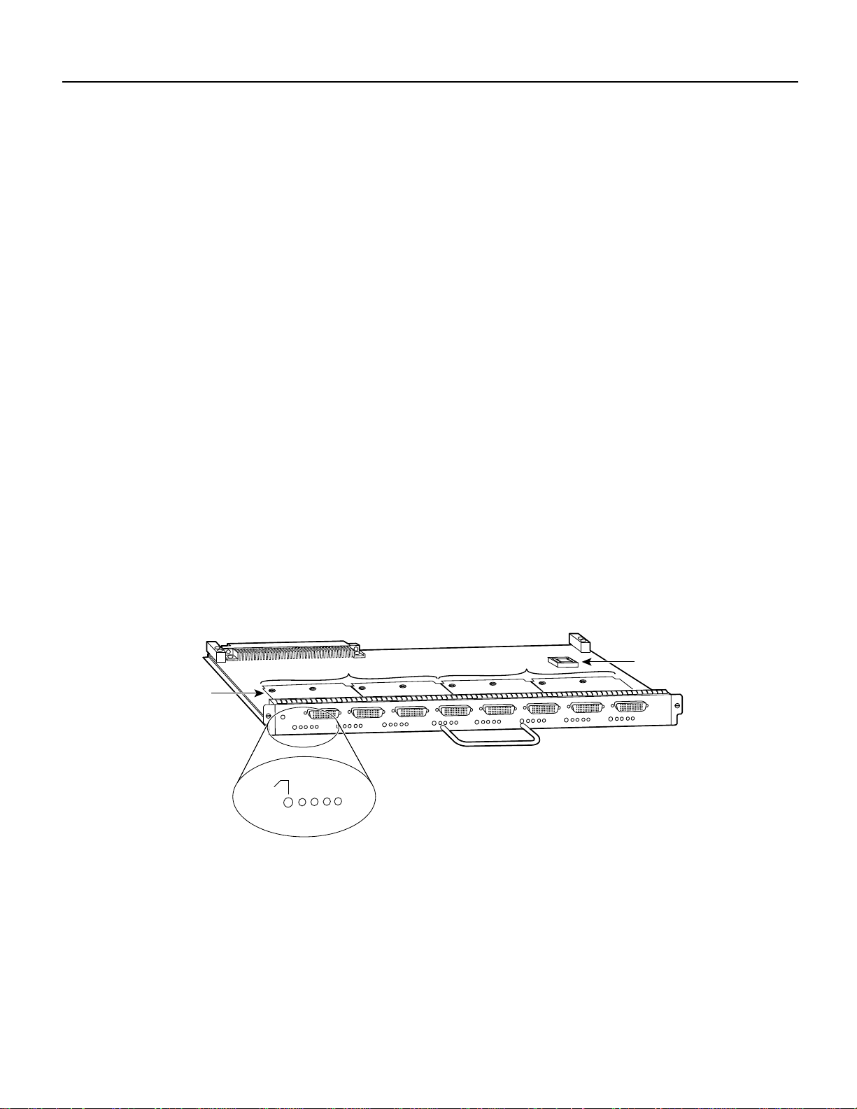
The FSIP (see Figure 1) provides four or eight channel-independent, synchronous serial ports that
support full-duplex operation at T1 (1.544 megabits per second [Mbps]) and E1 (2.048 Mbps)
speeds. The FSIP ships as Product Numbers CX-FSIP4(=) and CX-FSIP8(=).
Figure 1 Fast Serial Interface Processor (FSIP)
Port adapters
The ports are divided into two 4-port modules, each of which is controlled by a dedicated Motorola
MC68040 processor and contains 128 kilobytes (KB) of static random-access memory (SRAM).
Each module can support up to four T1 or three E1 interfaces, and an aggregate bandwidth of up to
6.132 Mbps at full-duplex operation.
Enabled
Module 1, ports 0-3
RxC
RxD
TxC
CONN
Module 2, ports 4-7
Translation of DCE LED
states for DCE ports:
RxC
RxD
TxC
CONN
=
TxC
=
TxD
=
RxC
=
CONN
U81, PLCC socket
with microcode ROM
H2004
The FSIP4 has one module for ports 0–3, and the FSIP8 has two modules, one for ports 0–3 and the
other for ports 4–7. To provide a high density of ports, the FSIP uses special port adapters and
adapter cables. A port adapter is a daughter board that provides the physical interface for two FSIP
serial ports. Each FSIP comprises an FSIP board with two or four port adapters. (One module is
equivalent to two port adapters.)
Fast Serial Interface Processor (FSIP) Installation and Configuration 3
Page 4

FSIP Interface Types
Additional port adapters are available as spares so that you can replace one that fails; however,you
cannot upgrade a 4-port FSIP to an 8-port FSIP by adding port adapters. (The 4-port FSIP is not
constructed to support additional ports after it leaves the factory; it contains the circuitry to control
only one 4-port module.)
An adapter cable provides the network connection for each port and determines the electrical
interface type and mode of that interface. (For more information, refer to the section “FSIP Port
Adapters, Interface Cables, and Connections” on page 20.)
Each serial port on the FSIP4 or FSIP8 can transmit and receive data at the rate of 6.132 Mbps;
however, if one or more ports consumes the full 6.132 Mbps bandwidth, then we strongly
recommend that the remaining ports be administratively shut down.
For example, you can configure four T1 interfaces on a module (one T1 on each port) such that they
do not exceed 6.132 Mbps, or you can configure one port to operate at up to 6.132 Mbps, and leave
the remaining three ports shut down. Note that some environments will support four E1 interfaces
per module without any problems; however, the type of electrical interface, the amount of traffic
processed, and the types of external data service units (DSUs) connected to the ports affect actual
rates.
FSIP Interface Types
Each port supports any of the available interface types: Electronics Industries
Association/Telecommunications Industries Association (EIA/TIA)-232, EIA/TIA-449,
E1-G.703/G.704, V.35, X.21, and EIA-530.
Note Prior to the acceptance of the EIA/TIA standards by the ANSI committee, they were referred
to as recommended standards called RS-232 and RS-449.
All interface types except EIA-530 can be individually configured for operation with either external
(data terminal equipment [DTE] mode) or internal (data communications equipment [DCE] mode)
timing signals; EIA-530 operates with external timing only.
In addition, all FSIP interface types support nonreturn to zero (NRZ) and nonreturn to zero inverted
(NRZI) format, and both 16-bit and 32-bit cyclic redundancy checks (CRCs). The default
configuration is for NRZ format and 16-bit CRC. Youcan change the default settings with software
commands. (See the section “Configuring the FSIP” on page 37.)
There is no default mode or clock rate set on the FSIP ports, although an internal clock signal is
present on all ports for DCE support. The internal clock also allows you to perform local loopback
tests without having to terminate the port or connect a cable. (All interface types except X.21 DTE
support loopback.)
To use the port as a DCE interface, you must set the clock rate and connect a DCE adapter cable. To
use the port as a DTE interface, you need only connect a DTE adapter cable to the port. Because the
serial adapter cables determine the mode and interface type, the FSIP port becomes a DTE when a
DTE cable is connected to it.
If a DTE cable is connected to a port with a clock rate set (using the clockrate command), the DTE
ignores the clock rate and uses the external clock signal that is sent from the remote DCE. (For a
brief description of the clockrate command, refer to the section “Configuring Timing (Clock)
Signals” on page 39.)
4 Fast Serial Interface Processor (FSIP) Installation and Configuration
Page 5

Each E1-G.703/G.704 interface is a 2.048-megabit per second (Mbps), E1 telecommunications
interface; all the other available FSIP interfaces are synchronous serial data communications
interfaces.G.703 is an International TelecommunicationUnion TelecommunicationStandardization
Sector(ITU-T)electricalandmechanical specification for connections between telecommunications
interfaces and data communications equipment (DTE).
Note The ITU-T carries out the functions of the former Consultative Committee for International
Telegraph and Telephone (CCITT).
Typically,G.703provides a means of connecting standard serial interfaces such as V.35 to telephone
linesor Postal TelephoneandTelegraph (PTT) networks. The E1-G.703/G.704 portadapter supports
point-to-point connections to Cisco 7000 series and Cisco 7500 series routers from 2.048-Mbps, E1
leased-line services, and eliminates the need for a separate, external data termination unit that is
typically used to convert standard serial interfaces, such as V.35, to E1-G.703/G.704.
Synchronous Serial Distance Limitations
Serial signals can travel a limited distance at any given bit rate; generally, the slower the baud rate,
the greater the distance. All serial signals are subject to distance limits beyond which a signal
degrades significantly or is completely lost. Table 1 lists the recommended maximum speeds and
distances for each FSIP serial interface type.
FSIP Interface Types
Table 1 Transmission Speed Versus Distance
EIA/TIA-232
Maximum Distances
Rate (bps) Feet Meters Feet Meters
2,400 200 60 4,100 1,250
4,800 100 30 2,050 625
9,600 50 15 1,025 312
19,200 25 7.6 513 156
38,400 12 3.7 256 78
56,000 8.6 2.6 102 31
1,544,000 (T1) – – 50 15
EIA/TIA-449, X.21, V.35, EIA-530
Maximum Distances
Balanced drivers allow EIA/TIA-449 signals to travel greater distances than EIA/TIA-232. The
recommended distance limits for EIA/TIA-449 shown in Table 1 are also valid for V.35, X.21, and
EIA-530. However, you can get good results at distances and rates far greater than these. While
EIA/TIA-449 and EIA-530 support 2-Mbps rates, and V.35 supports 4-Mbps rates without any
problems, we do not recommend exceeding published specifications for transmission speed versus
distance; do so at your own risk.
Fast Serial Interface Processor (FSIP) Installation and Configuration 5
Page 6

FSIP Installation Prerequisites
E1-G.703/G.704 Distance Limitations
Unbalanced G.703 interfaces allow for a longer maximum cable length than those specified for
balancedcircuits. Table 2 lists the maximumcablelengths for each FSIP E1-G.703/G.704 cabletype
by the connector used at the network (non-FSIP) end.
Table 2 E1-G.703/G.704 Maximum Cable Lengths
Connection Type BNC Twinax
Balanced – 300 m
Unbalanced 600 m –
FSIP Installation Prerequisites
Before you install the FSIP, ensure that your existing system components meet the compatibility
requirements described in this section. You should also review the safety and ESD-prevention
guidelines for avoiding bodily injury or equipment damage, and the list of parts and tools you will
need to perform the installation.
Software Requirements
The FSIP is compatible with any Cisco 7000 series router that is operating with the following
software and microcode:
• Software Release 9.17(5) or later
• SP Microcode Version 1.4 or later on ROM
• The system is configured to load SP Microcode Version 1.4 from ROM or a later version of SP
microcode from ROM or a file stored in Flash memory.
Caution SP Microcode Version 1.4 must reside in ROM; it cannot be loaded from Flash memory.
During the boot process, the system accesses the SP (or SSP) microcode. If the SP microcode ROM
contains a version earlier than 1.4 and the router contains an FSIP, the system might fail to boot
properly.
Note The FSIP is compatible with any of the currently shipping Cisco 7500 series routers.
Various show commands allow you to display and verify system status and configuration
information. The show version command displays the current hardware configuration and the
currently loaded and running version of system software. The show controllers cxbus command
lists all interfaces and includes the currently loaded and running microcode version for each. You
can check the version of the default ROM image either by removing the board and checking the
ROM labels or by configuring the system to load the microcode from ROM, restarting the system,
and using these same commands to check the running version. For details of these commands, refer
to the section “Using Show Commands to Check the Configuration” on page 46.
6 Fast Serial Interface Processor (FSIP) Installation and Configuration
Page 7

Startup Error Message
When the system starts up, it looks for boot instructions in the system configuration file and
hardware configuration register. These instructions cause the system to boot from one of three
possible sources: the default ROM software, an image stored in Flash memory, or a remote server.
Because the system must be able to retrieve and interpret these instructions before it can execute
them, it always performs a partial boot from the default ROMs first and, after retrieving the
instructions, it executes them and reboots if necessary.
In Cisco 7000 series routers, this partial boot is usually transparent to the user; however, it may
generate a harmless error message if the system ROMs contain a software version earlier than
Maintenance Release 9.17(5).
In the Cisco 7000 series, Maintenance Release 9.17(5) supports the FSIP, but earlier releases will
not recognize it. If the software ROMs in your system contain Maintenance Release 9.17(4) or
earlier, the initial, partial boot from that ROM image can cause the following message to be
displayed:
%UCODE-3-LDFAIL: Unable to download ucode FSIPn-n in slot 0, installed ucode loaded
must be a SIP serial interface
Booting gs7-k...
This message, which is displayed at each subsequent system startup (unless you remove the FSIP or
replace the system software ROMs with Maintenance Release 9.17[5] or later ROMs), does not
indicate a problem and should be ignored.
FSIP Installation Prerequisites
List of Parts and Tools
You need the following tools and parts to install or upgrade an FSIP. If you need additional
equipment, contact your service representative for ordering information.
• Number 2 Phillips screwdriver
• 3/16-inch flat-blade screwdriver
• Serial interface cable to connect the FSIP with the network
• ESD cord and wrist strap
Safety Guidelines
This section lists safety guidelines to follow when working with any equipment that connects to
electrical power or telephone wiring.
Safety Warnings
Safety warnings appear throughout this publication in procedures that, if performed incorrectly,
might harm you. A warning symbol precedes each warning statement.
Warning Means danger. You are in a situation that could cause bodily injury. Before you work on
any equipment, be aware of the hazards involved with electrical circuitry and be familiar with
standard practices for preventing accidents. To see translations of the warnings that appear in this
publication, refer to theRegulatoryComplianceand Safety Information document that accompanied
this device.
Fast Serial Interface Processor (FSIP) Installation and Configuration 7
Page 8

FSIP Installation Prerequisites
Waarschuwing Dit waarschuwingssymbool betekent gevaar. U verkeert in een situatie die
lichamelijk letsel kan veroorzaken. Voordat u aan enige apparatuur gaat werken, dient u zich bewust
te zijn van de bij elektrische schakelingen betrokken risico's en dient u op de hoogte te zijn van
standaard maatregelen om ongelukken te voorkomen. Voor vertalingen van de waarschuwingen die
in deze publicatie verschijnen, kunt u het document Regulatory Compliance and Safety Information
(Informatie over naleving van veiligheids- en andere voorschriften) raadplegen dat bij dit toestel is
ingesloten.
Varoitus Tämä varoitusmerkkimerkitseevaaraa.Olettilanteessa,jokavoijohtaaruumiinvammaan.
Ennen kuin työskentelet minkään laitteiston parissa, ota selvää sähkökytkentöihin liittyvistä
vaaroista ja tavanomaisista onnettomuuksien ehkäisykeinoista. Tässä julkaisussa esiintyvien
varoitusten käännökset löydät laitteen mukana olevasta Regulatory Compliance and Safety
Information -kirjasesta (määräysten noudattaminen ja tietoa turvallisuudesta).
Attention Ce symbole d'avertissement indique un danger. Vous vous trouvez dans une situation
pouvant causer des blessures ou des dommages corporels. Avant de travailler sur un équipement,
soyez conscient des dangers posés par les circuits électriques et familiarisez-vous avec les
procédures couramment utilisées pour éviter les accidents. Pour prendre connaissance des
traductions d’avertissements figurant dans cette publication, consultez le document Regulatory
Compliance and Safety Information (Conformité aux règlements et consignes de sécurité) qui
accompagne cet appareil.
Warnung Dieses Warnsymbol bedeutet Gefahr. Sie befinden sich in einer Situation, die zu einer
Körperverletzungführen könnte. BevorSiemit der Arbeit an irgendeinem Gerät beginnen,seien Sie
sich der mit elektrischen Stromkreisen verbundenen Gefahren und der Standardpraktiken zur
Vermeidung von Unfällen bewußt. Übersetzungen der in dieser Veröffentlichung enthaltenen
Warnhinweise finden Sie im Dokument Regulatory Compliance and Safety Information
(Informationen zu behördlichen Vorschriften und Sicherheit), das zusammen mit diesem Gerät
geliefert wurde.
Avvertenza Questo simbolo di avvertenza indica un pericolo. La situazione potrebbe causare
infortuni alle persone. Prima di lavorare su qualsiasi apparecchiatura, occorre conoscere i pericoli
relativiaicircuitielettrici ed essere al corrente dellepratiche standard per la prevenzione di incidenti.
La traduzione delle avvertenze riportate in questa pubblicazione si trova nel documento Regulatory
Compliance and Safety Information (Conformità alle norme e informazioni sulla sicurezza) che
accompagna questo dispositivo.
Advarsel Dette varselsymbolet betyr fare. Du befinner deg i en situasjon som kan føre til
personskade. Før du utfører arbeid på utstyr, må du vare oppmerksom på de faremomentene som
elektriskekretser innebærer,samt gjøre deg kjent medvanligpraksis når det gjelder å unngå ulykker.
Hvis du vil se oversettelser av de advarslene som finnes i denne publikasjonen, kan du se i
dokumentet Regulatory Compliance and Safety Information (Overholdelse av forskrifter og
sikkerhetsinformasjon) som ble levert med denne enheten.
Aviso Este símbolo de aviso indica perigo. Encontra-se numa situação que lhe poderá causar danos
físicos. Antes de começar a trabalhar com qualquer equipamento, familiarize-se com os perigos
relacionados com circuitos eléctricos, e com quaisquer práticas comuns que possam prevenir
possíveis acidentes. Para ver as traduções dos avisos que constam desta publicação, consulte o
documento Regulatory Compliance and Safety Information (Informação de Segurança e
Disposições Reguladoras) que acompanha este dispositivo.
¡Advertencia! Este símbolo de aviso significa peligro. Existe riesgo para su integridad física.
Antes de manipular cualquier equipo, considerar los riesgos que entraña la corriente eléctrica y
familiarizarse con los procedimientos estándar de prevención de accidentes. Para ver una traducción
de las advertencias que aparecen en esta publicación, consultar el documento titulado Regulatory
Compliance and Safety Information (Información sobre seguridad y conformidad con las
disposiciones reglamentarias) que se acompaña con este dispositivo.
8 Fast Serial Interface Processor (FSIP) Installation and Configuration
Page 9

Electrical Equipment
FSIP Installation Prerequisites
Varning! Denna varningssymbol signalerar fara. Du befinner dig i en situation som kan leda till
personskada. Innan du utför arbete på någon utrustning måste du vara medveten om farorna med
elkretsar och känna till vanligt förfarande för att förebygga skador. Se förklaringar av de varningar
som förkommer i denna publikation i dokumentet Regulatory Compliance and Safety Information
(Efterrättelse av föreskrifter och säkerhetsinformation), vilket medföljer denna anordning.
Follow these basic guidelines when working with any electrical equipment:
• Before beginning any procedures requiring access to the chassis interior, locate the emergency
power-off switch for the room in which you are working.
• Disconnect all power and external cables before moving a chassis.
• Do not work alone if potentially hazardous conditions exist.
• Never assume that power is disconnected from a circuit; always check.
• Do not perform any action that creates a potential hazard to people or makes the equipment
unsafe.
• Carefully examine your work area for possible hazards such as moist floors, ungrounded power
extension cables, and missing safety grounds.
Telephone Wiring
Use the following guidelines when working with any equipment that is connected to telephone
wiring or to other network cabling:
• Never install telephone wiring during a lightning storm.
• Never install telephone jacks in wet locations unless the jack is specifically designed for wet
locations.
• Never touch uninsulated telephone wires or terminals unless the telephone line has been
disconnected at the network interface.
• Use caution when installing or modifying telephone lines.
Preventing Electrostatic Discharge Damage
Electrostatic discharge (ESD) damage, which can occur when electronic cards or components are
improperly handled, results incomplete or intermittentfailures. Electromagnetic interference (EMI)
shielding, connectors, and a handleare integral components of the carrier.Althoughthemetalcarrier
helps to protect the board from ESD, use a preventive antistatic strapwheneverhandling an interface
processor. Handle the carriers by the handles and the carrier edges only; never touch the boards or
connector pins.
Following are guidelines for preventing ESD damage:
• Always use an ESD-preventive wrist or ankle strap and ensure that it makes good skin contact;
connect the equipment end of the strap to a captive installation screw on an installed power
supply.
• When installing an interface processor, use the ejector levers to properly seat the bus connectors
in the backplane, then tighten both captive installation screws. These screws prevent accidental
removal, provide proper grounding for the system, and help ensure that the bus connectors are
seated in the backplane.
Fast Serial Interface Processor (FSIP) Installation and Configuration 9
Page 10

FSIP Installation Prerequisites
• When removing an interface processor, use the handle to pull the interface processor out slowly
while keeping your other hand underneath the carrier to guide it straight out of the slot.
• Handle carriers by the handles and carrier edges only; avoid touching the board or connectors.
• Place a removedinterface processor board-side-up on an antistatic surface or in a static shielding
bag. If you plan to return the component to the factory, immediately place it in a static shielding
bag.
• Avoid contact between the interface processor and clothing. The wrist strap only protects the
board from ESD voltages on the body; ESD voltages on clothing can still cause damage.
• Never attempt to remove an interface processor printed circuit board from the metal interface
processor carrier.
Caution Forsafety,periodicallychecktheresistance valueof the antistatic strap. Themeasurement
should be between 1 and 10 megohms.
Interface Processor Slot Locations
The FSIP is installed in the interface processor slots in the Cisco 7000 series and Cisco 7500 series
routers. The interface processor slots in the Cisco 7000 series and Cisco 7500 series routers are as
follows:
• Cisco 7000—slots 0 through 4 (See Figure 2.)
• Cisco 7010—slots 0 through 2 (See Figure 3.)
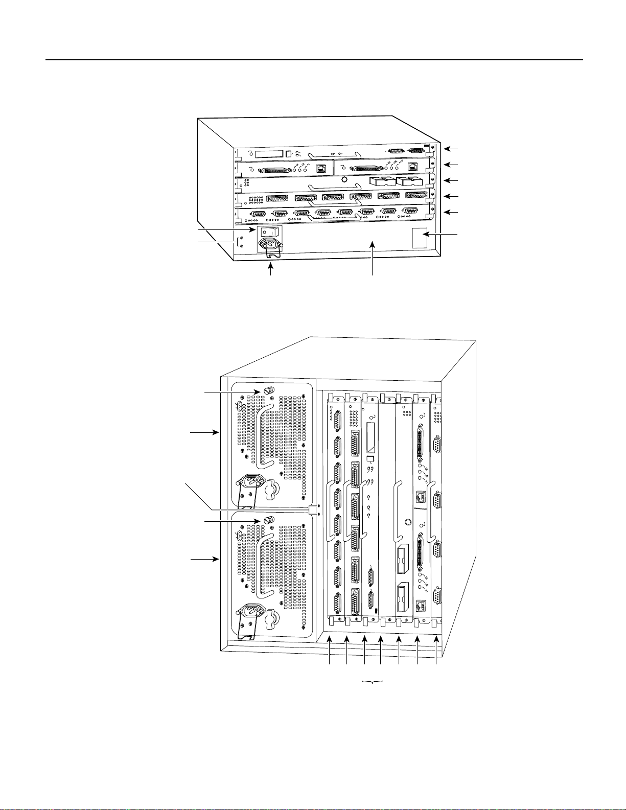
• Cisco 7505—slots 0 through 3 (See Figure 4.)
• Cisco 7507—slots 0 and 1, and slots 4 through 6 (See Figure 5.)
• Cisco 7513—slots 0 through 5, and slots 8 through 12 (See Figure 6.)
Note The interface processor slots are oriented horizontally in the Cisco 7010 and Cisco 7505, and
vertically in the Cisco 7000, Cisco 7507, and Cisco 7513.
10 Fast Serial Interface Processor (FSIP) Installation and Configuration
Page 11
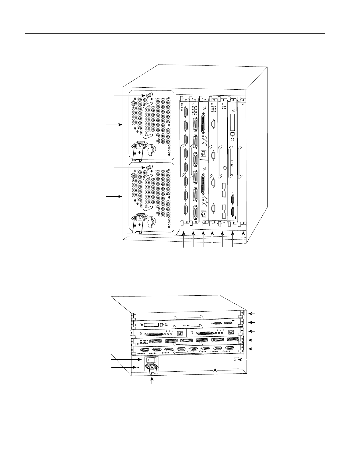
Figure 2 Cisco 7000 Interface Processor Slots
Captive
installation screw
Upper
power supply
DC FAIL
AC POWER
ENABLE
FSIP Installation Prerequisites
NORMAL
I
O
Captive
installation screw
DC FAIL
AC POWER
Lower
power supply
I
O
Interface processor slots 0
Figure 3 Cisco 7010 Interface Processor Slots
EJECT
SLOT 1
SLOT 0
ENABLE
2
1
3 4 RSP
CPU HALT
RESET
AUX.
CONSOLE
7000
slot 5
ROUTE SWITCH PROCESSOR
H5288
RSP
7000CI
slot 6
Power switch
Chassis ground
screw
NORMAL
ENABLE
EJECT
Power receptacle
Fast Serial Interface Processor (FSIP) Installation and Configuration 11
RSP7000CI slot 4
SLOT 1
SLOT 0
CPU HALT
RESET
ENABLE
AUX.
ROUTE SWITCH PROCESSOR
CONSOLE
RSP7000 slot 3
Interface processor slot 2
Interface processor slot 1
Interface processor slot 0
DC OK LED
H5874
AC-input power supply
Page 12
FSIP Installation Prerequisites
Figure 4 Cisco 7505 Interface Processor Slots
NORMAL
EJECT
SLOT 1
SLOT 0
ENABLE
CPU HALT
ENABLE
Power switch
Chassis
grounding
receptacles
Power receptacle AC-input power supply
Figure 5 Cisco 7507 Interface Processor Slots
Captive
installation screw
Upper
power supply
DC FAIL
AC POWER
RESET
AUX.
ROUTE SWITCH PROCESSOR
CONSOLE
RSP slot
Interface processor slot 3
Interface processor slot 2
Interface processor slot 1
Interface processor slot 0
DC OK LED
H2761
NORMAL
ENABLE
Chassis
grounding
receptacles
Captive
installation screw
Lower
power supply
DC FAIL
AC POWER
EJECT
SLOT 1
I
O
I
O
Slot 0
SLOT 0
MASTER
SLAVE
SLAVE/MASTER
CPU HALT
RESET
AUX.
ROUTE SWITCH PROCESSOR 2
CONSOLE
2
1
34 5 6
ENABLE
H3888
RSP slots
12 Fast Serial Interface Processor (FSIP) Installation and Configuration
Page 13
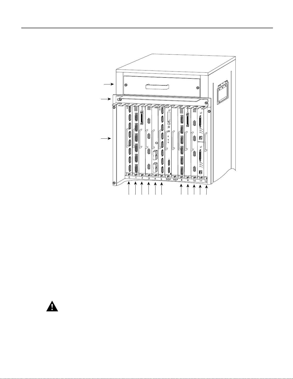
Figure 6 Cisco 7513 Interface Processor Slots
Blower module
FSIP Installation Prerequisites
Cable-management
bracket
Card cage and
NORMAL
SLOT 0
SLAVE
SLAVE/MASTER
processor modules
AUX.
CONSOLE
Interface processor slots
0
2
1
4
3
589101112
Guidelines for Interface Processor Removal and Installation
This section describes the mechanical functions of system components and emphasizes the
importance of following correct procedures to avoidunnecessary board failures. Specific procedures
follow these general background and safety guidelines in the section “Interface Processor
Replacement Procedures” on page 15.
EJECT
SLOT 1
MASTER
CPU HALT
RESET
ROUTE SWITCH PROCESSOR 2
ENABLE
ENABLE
H10000
You can remove and replace interface processors while the system is operating; you do not need to
notify the software or reset the system power. This functionality enables you to add, remove, or
replace interface processors with the system online, which provides a method that is seamless to end
users on the network, maintains all routing information, and ensures session preservation.
After an interface processor is reinstalled, the system brings on line only interfaces that match the
current configuration and were previously configured as up; all others require that you configure
them with the configure command.
Caution The system can indicate a hardware failure if you do not follow proper procedures.
Remove or insert only one interface processor at a time. Allow at least 15 seconds for the system to
complete the preceding tasks before removing or inserting another interface processor. Disrupting
the sequence before the system completes its verification can cause the system to interpret hardware
failures.
Fast Serial Interface Processor (FSIP) Installation and Configuration 13
Page 14

FSIP Installation Prerequisites
Note We recommend that you install interface processors starting with the slots closest to the RSPs
and work out concentrically from there. This will help to ensure that rejection of electromagnetic
interference (EMI) is maintained.
All interface processors have ejector levers that allowyou to firmly seat an interface processor in the
interface processor slot (see Figure 8). The function of the ejector leversis to align and seat the card
connectors in the backplane. Failure to use the ejector levers and insert the interface processor
properly can disrupt the order in which the pins make contact with the backplane.
Follow the installation and removal instructions carefully, and review the following examples of
incorrect insertion practices and results:
• Using the handle to force the interface processor all the way into the slot can pop the ejector
levers out of their springs. If you then try to use the ejector levers to seat the interface processor,
the first layer of pins (which are already mated to the backplane) can disconnect and then remate
with the backplane, which the system interprets as a board failure.
• Using the handle to force or slam the interface processor all the way into the slot can also damage
the pins on the board connectors if they are not aligned properly with the backplane.
• When using the handle (rather than the ejector levers) to seat the interface processor in the
backplane, you might need to pull the interface processor back out and push it in again to align
it properly.
Even if the connector pins are not damaged, the pins mating with and disconnecting from the
backplane will cause the system to interpret a board failure. Using the ejector levers ensures that
the board connector mates with the backplane in one continuous movement.
• Using the handle to insert or remove an interface processor, or failing to push the ejector levers
to the full parallel position, can leavesome(not all) of the connector pins mated to the backplane,
a state that will hang the system. Using the ejector levers and making sure that they are pushed
fully into position ensuresthat all three layers of pins aremated with (or free from) the backplane.
It is also important to use the ejector levers when removing an interface processor to ensure that the
board connector pins disconnect from the backplane in the logical sequence expected by the system.
Any processor module (interface processor or RSP) that is only partially connected to the backplane
can hang the bus. (Detailed steps for correctly installing and removing an interface processor follow
in the section “Interface Processor Replacement Procedures.”)
14 Fast Serial Interface Processor (FSIP) Installation and Configuration
Page 15

Interface Processor Replacement Procedures
Typically, your interface processors arrive preinstalled in your Cisco 7000 series and Cisco 7500
series routers (with the exception of the Cisco 7513); however, occasionally you might have to
remove and replace interface processors for maintenance.
The following sections describe the procedures for removing or installing an interface processor.
(Refer the section “Guidelines for Interface Processor Removal and Installation” before removing
an interface processor while power to the system is on.)
Caution To avoid erroneous failure messages, remove or insert only one interface processor at a
time. Also, after inserting or removing an interface processor, allow at least 15 seconds before
removing or inserting another interface processor so that the system can reinitialize and note the
current configuration of all interfaces.
Note If you install or remove other interface processors in a Cisco 7000 series or Cisco 7500 series
routerwith a CT3IP installed, you mighthavetorebootthesystem after the removal and replacement
of that interface processor. (In general, and to prevent system problems, we recommend you follow
the procedures described in this section and the guidelines described in the preceding section
“Guidelines for Interface Processor Removal and Installation.”)
Interface Processor Replacement Procedures
Fast Serial Interface Processor (FSIP) Installation and Configuration 15
Page 16

Interface Processor Replacement Procedures
Removing an Interface Processor
If you are replacing a failed interface processor, remove the existing board first, then install the new
interface processor in the same slot.
Note In Cisco 7507 or Cisco 7513 systems, on-line insertion and removal of any interface
processor in either CyBus might cause the slave RSP2 to reboot with a bus error or a processor
memory parity error. The master RSP will recover from this event and issue a “cBus Complex
Restart” message. Cisco 7507 and Cisco 7513 systems that are configured with an RSP4 as the
system slave are not affected and will not experience this problem.
If you have a Cisco 7507 or a Cisco 7513 with an RSP2 configured as the system slave, we strongly
recommend that you use the following procedure to remove and replace an interface processor:
Step 1 Remove the slave RSP2.
Step 2 Wait 15 seconds.
Step 3 Remove and replace the interface processor using the procedures in this publication.
Step 4 Wait 15 seconds.
Step 5 Reinsert the slave RSP2.
Figure 7 shows proper handling of an interface processor during installation. Before you remove an
interface processor that you will not replace, or replace an interface processor component, we
recommend you shut down (disable) the interfaces to prevent anomalies when you reinstall the new
or reconfigured interface processor. When you shut down an interface, it is designated
administratively down in the show command displays.
Figure 7 Handling Interface Processors during Installation (Horizontal Orientation Shown)
H4714
Captive installation
screws
16 Fast Serial Interface Processor (FSIP) Installation and Configuration
Page 17

Interface Processor Replacement Procedures
Use the following procedure to remove an interface processor:
Step 1 Disconnect the interface processor’s cables from the interface ports.
Step 2 Loosen the captive installation screws at the ends of the interface processor faceplate.
(See Figure 8a.)
Caution Always use the ejector levers to remove or install an interface processor. Failure to do so
can cause erroneous system error messages, indicating a board failure.
Step 3 Place your thumbs on the upper and lowerejector levers and simultaneously push the top
ejector lever up and the bottom ejector lever down (in the opposite direction from that
shown in Figure 8c) to release an interface processor from the backplane connector.
Step 4 Grasp the interface processor handle with one hand and place your other hand under the
carrier to guide the interface processor out of the slot. (See Figure 7.) Avoid touching the
board or any connector pins.
Step 5 Carefully pull the interface processor straight out of the slot, keeping one hand under the
carrier to guide it. (See Figure 7.) Keep the interface processor parallel to the backplane.
Step 6 Place the removed interface processor on an antistatic mat or foam pad, or place it in an
antistatic bag if you will return it to the factory.
Step 7 If the interface processor slot is to remain empty, install an interface processor filler
(MAS-7000BLANK=) to keep dust out of the chassis and to maintain proper airflow
through the interface processor compartment.
Installing an Interface Processor
Interface processors slide into any available interface processor slot and connect directly to the
backplane. The backplane slots are keyed so that interface processors can be installed only in
interface processor slots. Interface processor fillers, which are blank interface processor carriers,
occupy empty slots to maintain consistent air flow through the interface processor compartment.
If you install a new interface processor, you have to first remove the interface processor filler from
the available interface processor slot. Figure 8 shows functional details of inserting an interface
processor and using ejector levers. (Figure 7 shows proper handling of an interface processor during
installation.)
Note There are no restrictions on slot locations or interfaceprocessor sequence, andyou can install
the interface processor in any available interface processor slot; however, in the Cisco 7507 and
Cisco 7513, we recommend that you install interface processors starting with the slots closest to the
RSPs and work out concentrically from there. This will help prevent electromagnetic interference
(EMI).
Caution Remove or insert only one interface processor at a time. Allow at least 15 seconds for the
system to complete the preceding tasks before removing or inserting another interface processor.
Disrupting the sequence before the system completes its verification can cause the system to
interpret this as a hardware failure.
Fast Serial Interface Processor (FSIP) Installation and Configuration 17
Page 18

Interface Processor Replacement Procedures
Use the following procedure to install an interface processor:
Step 1 Ensure that a console terminal is connected to the RP (or RSP) Console port and that the
console is turned on.
Step 2 Choose an available interface processor slot for the interface processor, and ensure that
the interface processor’s cable is of a sufficient length to connect the interface processor
withany external equipment. Werecommendthatyou install interface processors starting
with the slots closest to the RSPs and work out concentrically from there. This will help
prevent EMI.
Step 3 Interface processors and interface processor fillers are secured with two captive
installation screws. (See Figure 8a.) Use a flat-blade screwdriver to loosen the captive
installation screws and remove the interface processor filler (or the existing interface
processor) from the slot. If you remove an interface processor,immediately place it in an
antistatic bag to prevent damage from electrostatic discharge.
18 Fast Serial Interface Processor (FSIP) Installation and Configuration
Page 19

Interface Processor Replacement Procedures
Figure 8 Location of Ejector Levers and Captive Installation Screws
Interface processor
card slot
Ejector
lever
Interface processor card
carrier guide (black)
Step 4
a
Captive
installation
screw
c
b
H9846
Hold the interface processor handle with one hand, and place your other hand under the
carrier to support the interface processor (see Figure 7); guide the carrier into the slot.
Avoid touching the card or any connector pins.
Caution To prevent ESD damage, handle interface processors by the handles and carrier edges
only.
Step 5 Place the back of the interface processor in the slot and align the notch on the bottom of
the carrier with the groove in the slot. (See Figure 8a.)
Step 6 While keeping the interface processor parallel to the backplane, carefully slide the
interface processor into the slot until the back of the faceplate makes contact with the
ejector levers, then stop. (See Figure 8b.)
Fast Serial Interface Processor (FSIP) Installation and Configuration 19
Page 20

FSIP Port Adapters, Interface Cables, and Connections
Caution Always use the ejector levers when installing or removing processor modules. A module
that is partially seated in the backplane will cause the system to hang and subsequently crash.
Step 7 Using the thumb and forefinger of each hand to pinch each ejector lever, simultaneously
push the top ejector lever down and the bottom ejector lever up until both are parallel to
the faceplate. (See Figure 8c.)
Step 8 Tighten the captive screws on the top and bottom of the interface processor faceplate to
prevent the interface processor from becoming partially dislodged from the backplane
and ensure proper EMI shielding. (These screws must be tightened to meet EMI
specifications.)
Caution To ensure adequate space for additional interface processors, always tighten the captive
installation screws on each newly installed interface processor before you insert any additional
interface processors. These screws also prevent accidental removal, and provide proper grounding
and EMI shielding for the system.
FSIP Port Adapters, Interface Cables, and Connections
The universal port adapters and adapter cables allow eight interface ports on an FSIP, regardless of
the size of the connectors typically used with each electrical interface type. (See Figure 9.)
Figure 9 Universal and E1-G.703/G.704 Serial Port Adapters
Port adapters are field-replaceable daughter boards mounted to the FSIP, and each provides two
high-density connectors for two FSIP ports.
All FSIP port adapters use an identical 60-pin, D-shell receptacle that supports all interface types:
EIA/TIA-232, V.35, EIA/TIA-449, X.21, and EIA-530. An exception to this is the E1-G.703/G.704
port adapter, which uses a 15-pin, D-shell receptacle.
FSIP Interface Cables
Each port requires a serial interface adapter cable that provides the interface between the
high-density FSIP port and the standard connectors that are commonly used for each electrical
interface type. Rate of data transmission depends on the type of electrical interface: EIA/TIA-232
for speeds of 64 kilobits per second (kbps) and below; X.21, EIA/TIA-449, V.35, or EIA-530 for
higher speeds.
Universal
H2400
E1-G.703/G.704
Note The adapter cable determines the electrical interface type and mode of the port to which it is
connected.
20 Fast Serial Interface Processor (FSIP) Installation and Configuration
Page 21

FSIP Port Adapters, Interface Cables, and Connections
The router (FSIP) end of all adapter cables is a 60-pin, D-shell plug that connects to the 60-pin port
on the FSIP. The network end of the cable is an industry-standard connector for the type of electrical
interface that the cable supports. For most interface types, the adapter cable for DTE mode uses a
plug at the network end, and the cable for DCE mode uses a receptacle at the network end.
Exceptions are V.35 adapter cables, which are available with either a V.35 plug or a receptacle for
eithermode, and the EIA-530 adaptercable, which is available only in DTE mode witha DB-25 plug
at the network end.
The mode (DCE or DTE) is labeled on the molded plastic connector shell at the ends of all cables
except V.35 (which uses the standard Winchester block-type connector instead of a molded plastic
D-shell).
Followingare the availableportadapter and cable options for the mode and network-end connectors
for each synchronous serial cable listed by product number:
• PA-7KF-SPA(=)—Universal synchronous serial port adapter
• CAB-232MT(=)—EIA/TIA-232 DTE mode cable with a DB-25 plug
• CAB-232FC(=)—EIA/TIA-232 DCE mode cable with a DB-25 receptacle
• CAB-449MT(=)—EIA/TIA-449 DTE mode cable with a 37-pin D-shell plug
• CAB-449FC(=)—EIA/TIA-449 DCE mode cable with a 37-pin D-shell receptacle
• CAB-V35MT(=)—V.35 DTE mode cable or DCE mode (CAB-V35MC=) with a 34-pin
Winchester-type V.35 plug
• CAB-V35FT(=)—V.35 DTE mode cable or DCE mode (CAB-V35FC=) with a 34-pin
Winchester-type V.35 receptacle
• CAB-X21MT(=)—X.21 DTE mode cable with a DB-15 plug
• CAB-X21FC(=)—X.21 DCE mode with a DB-25 receptacle
• CAB-530MT(=)—EIA-530 DTE mode cable with a DB-25 plug
Following are the available port adapter and cable options for the E1-G.703/G.704 interface:
• PA-7KF-E1/120(=)—Dual-port E1-G.703/G.704, 120 ohm, balanced port adapter
• PA-7KF-E1/75(=)—Dual-port E1-G.703/G.704, 75 ohm, unbalanced port adapter
• CAB-E1-TWINAX(=)—E1 cable, TWINAX, 120 ohm, balanced, 5 meters
• CAB-E1-DB15(=)—E1 cable, DB-15, 120 ohm, balanced, 5 meters
• CAB-E1-BNC(=)—E1 cable, BNC, 75 ohm, unbalanced, 5 meters
All cables and port adapters are available as spare parts (=).
Forreplacement instructions, refer to the configuration note that shipped with yourreplacement port
adapter. For cable pinouts, refer to the section “FSIP Port Adapter Interface and Cable Pinouts” on
page 23.
Figure 10 shows the synchronous serial port adapter cables for connecting the FSIP port adapters to
your network.
Fast Serial Interface Processor (FSIP) Installation and Configuration 21
Page 22

FSIP Port Adapters, Interface Cables, and Connections
Figure 10 Synchronous Serial Port Adapter Cables
Router (FSIP) connections
EIA/TIA-232 EIA-530
EIA/TIA-449 V.35 X.21
Network connections at the modem or CSU/DSU
H1727
22 Fast Serial Interface Processor (FSIP) Installation and Configuration
Page 23

FSIP Port Adapters, Interface Cables, and Connections
Figure 11, Figure 12, and Figure 13 show the unbalanced and balanced cables used for connecting
the E1-G.703/G.704 port adapter and your network. The port-adapter end of each cable has a DB-15
connector.
Figure 11 E1-G.703/G.704 Interface Cable for Unbalanced Connections (with BNC Connectors and
Coaxial Cables)
H2421
Figure 12 E1-G.703/G.704 Interface Cable for Balanced Connections (withDB-15 Connectors on Both
Ends)
Figure 13 E1-G.703/G.704 Interface Cable for Balanced Connections (with Twinax Connectors and
Cables)
Caution
It is a requirement of the statutory approval of the E1-G.703/G.704 interface that the
jackscrews of the connector backshell be securely screwed down while the FSIP is operating.
Metric (M3) thumbscrews are included with each port adapter cable to allow connections to devices
that use metric hardware. Because the FSIP uses a special, high-density port that requires special
adapter cables for each electrical interface type, we recommend that you obtain serial interface
cables from the factory.
FSIP Port Adapter Interface and Cable Pinouts
The FSIP supports EIA/TIA-232, EIA/TIA-449, X.21, V.35, and EIA-530 serial interfaces and the
E1-G.703/G.704 interface. All FSIP ports use a universal port adapter,which is a 60-pin receptacle
that supports all available interface types. A special synchronous serial adapter cable, which is
required for each synchronous port, determines the electrical interface type and mode of the
synchronous serial interface. The router (FSIP) end of all of the adapter cables is a 60-pin plug; the
connectors at the network end are the standard connectors used for the respective interfaces. An
exception to this is the E1-G.703/G.704 port adapter, which uses a 15-pin, D-shell receptacle.
H2476
H2424
Fast Serial Interface Processor (FSIP) Installation and Configuration 23
Page 24

FSIP Port Adapters, Interface Cables, and Connections
All synchronous serial interface types except EIA-530 are available in DTE or DCE format: DTE
with a plug connector at the network end and DCE with a receptacle at the network end. V.35 is
available in either mode with either gender at the network end. EIA-530 is available in DTE only.
The tables that follow list the signal pinouts for both the DTE and DCE mode serial port adapter
cables for each FSIP interface type:
• Table 3, on page 24, lists the EIA/TIA-232 pinouts
• Table 4, on page 25, lists the EIA/TIA-449 pinouts
• Table 5, on page 26, lists the X.21 pinouts
• Table 6, page 27, lists the V.35 pinouts
• Table 7, on page 28, lists the EIA-530 pinouts
• Table 8, on page 29, lists the E1-G.703/G.704 pinouts
Table 3 EIA/TIA-232 Adapter Cable Signals
DTE Cable DCE Cable
FSIP End,
1
HD
60-Position
Plug
Signal Pin Pin Signal Signal Pin Pin Signal
Shield ground 46 1 Shield ground Shield ground 46 1 Shield ground
TxD/RxD 41 —> 2 TxD RxD/TxD 36 <— 2 TxD
RxD/TxD 36 <— 3 RxD TxD/RxD 41 —> 3 RxD
RTS/CTS 42 —> 4 RTS CTS/RTS 35 <— 4 RTS
CTS/RTS 35 <— 5 CTS RTS/CTS 42 —> 5 CTS
DSR/DTR 34 <— 6 DSR DTR/DSR 43 —> 6 DSR
Circuit ground 45 7 Circuit ground Circuit ground 45 7 Circuit ground
DCD/LL 33 <— 8 DCD LL/DCD 44 —> 8 DCD
TxC/NIL 37 <— 15 TxC TxCE/TxC 39 —> 15 TxC
RxC/TxCE 38 <— 17 RxC NIL/RxC 40 —> 17 RxC
LL/DCD 44 —> 18 LTST DCD/LL 33 <— 18 LTST
DTR/DSR 43 —> 20 DTR DSR/DTR 34 <— 20 DTR
TxCE/TxC 39 —> 24 TxCE RxC/TxCE 38 <— 24 TxCE
Mode 0
Ground
Mode_DCE
1. HD = high density.
50
51
52
Network
End,
DB-25 Plug
Shorting
group
FSIP End,
HD
60-Position
Plug
Mode 0
Ground
Network End,
DB-25
Receptacle
50
51 Shorting group
24 Fast Serial Interface Processor (FSIP) Installation and Configuration
Page 25

FSIP Port Adapters, Interface Cables, and Connections
Table 4 EIA/TIA-449 Adapter Cable Signals
DTE Cable DCE Cable
FSIP End,
1
HD
60-Position
Plug
Network
End,
DB-37 Plug
FSIP End,
HD
60-Position
Plug
Network End,
DB-37
Receptacle
Signal Pin Pin Signal Signal Pin Pin Signal
Shield ground 46 1 Shield
Shield ground 46 1 Shield ground
ground
TxD/RxD+ 11 —> 4 SD+ RxD/TxD+ 28 <— 4 SD+
TxD/RxD– 12 —> 22 SD– RxD/TxD– 27 <— 22 SD–
TxC/RxC+ 24 <— 5 ST+ TxCE/TxC+ 13 —> 5 ST+
TxC/RxC– 23 <— 23 ST– TxCE/TxC– 14 —> 23 ST–
RxD/TxD+ 28 <— 6 RD+ TxD/RxD+ 11 —> 6 RD+
RxD/TxD– 27 <— 24 RD– TxD/RxD– 12 —> 24 RD–
RTS/CTS+ 9 —> 7 RS+ CTS/RTS+ 1 <— 7 RS+
RTS/CTS– 10 —> 25 RS– CTS/RTS– 2 <— 25 RS–
RxC/TxCE+ 26 <— 8 RT+ TxC/RxC+ 24 —> 8 RT+
RxC/TxCE– 25 <— 26 RT– TxC/RxC– 23 —> 26 RT–
CTS/RTS+ 1 <— 9 CS+ RTS/CTS+ 9 —> 9 CS+
CTS/RTS– 2 <— 27 CS– RTS/CTS– 10 —> 27 CS–
LL/DCD 44 —> 10 LL NIL/LL 29 —> 10 LL
Circuit ground 45 37 SC Circuit ground 30 37 SC
DSR/DTR+ 3 <— 11 ON+ DTR/DSR+ 7 —> 11 ON+
DSR/DTR– 4 <— 29 ON– DTR/DSR– 8 —> 29 ON–
DTR/DSR+ 7 —> 12 TR+ DSR/DTR+ 3 <— 12 TR+
DTR/DSR– 8 —> 30 TR– DSR/DTR– 4 <— 30 TR–
DCD/DCD+ 5 <— 13 RR+ DCD/DCD+ 5 —> 13 RR+
DCD/DCD– 6 <— 31 RR– DCD/DCD– 6 —> 31 RR–
TxCE/TxC+ 13 —> 17 TT+ RxC/TxCE+ 26 <— 17 TT+
TxCE/TxC– 14 —> 35 TT– RxC/TxCE– 25 <— 35 TT–
Circuit ground 15 19 SG Circuit ground 15 19 SG
Circuit ground 16 20 RC Circuit ground 16 20 RC
Mode 1
Ground
Ground
Mode_DCE5152
1. HD = high density.
49
48
Shorting
group
Shorting
group
Mode 1
Ground
49
48
Shorting group
Fast Serial Interface Processor (FSIP) Installation and Configuration 25
Page 26

FSIP Port Adapters, Interface Cables, and Connections
Table 5 X.21 Adapter Cable Signals
DTE Cable DCE Cable
FSIP End,
1
HD
60-Position
Plug
Signal Pin Pin Signal Signal Pin Pin Signal
Shield ground 46 1 Shield ground Shield ground 46 1 Shield ground
TxD/RxD+ 11 —> 2 Transmit+ RxD/TxD+ 28 <— 2 Transmit+
TxD/RxD– 12 —> 9 Transmit– RxD/TxD– 27 <— 9 Transmit–
RTS/CTS+ 9 —> 3 Control+ CTS/RTS+ 1 <— 3 Control+
RTS/CTS – 10 —> 10 Control– CTS/RTS – 2 <— 10 Control–
RxD/TxD+ 28 <— 4 Receive+ TxD/RxD+ 11 —> 4 Receive+
RxD/TxD– 27 <— 11 Receive– TxD/RxD– 12 —> 11 Receive–
CTS/RTS+ 1 <— 5 Indication+ RTS/CTS+ 9 —> 5 Indication+
CTS/RTS – 2 <— 12 Indication– RTS/CTS– 10 —> 12 Indication–
RxC/TxCE+ 26 <— 6 Timing+ TxC/RxC+ 24 —> 6 Timing+
RxC/TxCE– 25 <— 13 Timing– TxC/RxC – 23 —> 13 Timing–
Circuit ground 15 8 Circuit ground Circuit ground 15 8 Circuit ground
Ground
Mode_2
Ground
Mode_DCE
1. HD = high density.
48
47
51
52
Network
End,
DB-15 Plug
Shorting
group
Shorting
group
FSIP End, HD
60-Position
Plug
Ground
Mode_2
Ground
Mode_DCE
48
47
51
52
Network End,
DB-15
Receptacle
Shorting
group
26 Fast Serial Interface Processor (FSIP) Installation and Configuration
Page 27

FSIP Port Adapters, Interface Cables, and Connections
Table 6 V.35 Adapter Cable Signals
DTE Cable DCE Cable
FSIP End,
1
HD
60-Position
Plug
Network
End,
34-Position
Plug
FSIP End,
HD
60-Position
Plug
Network End,
34-Position
Receptacle
Signal Pin Pin Signal Signal Pin Pin Signal
Shield ground 46 A Frame ground Shield ground 46 A Frame ground
Circuit ground 45 B Circuit
Circuit ground 45 B Circuit ground
ground
RTS/CTS 42 —> C RTS CTS/RTS 35 <— C RTS
CTS/RTS 35 <— D CTS RTS/CTS 42 —> D CTS
DSR/DTR 34 <— E DSR DTR/DSR 43 —> E DSR
DCD/LL 33 <— F RLSD LL/DCD 44 —> F RLSD
DTR/DSR 43 —> H DTR DSR/DTR 34 <— H DTR
LL/DCD 44 —> K LT DCD/LL 33 <— K LT
TxD/RxD+ 18 —> P SD+ RxD/TxD+ 28 <— P SD+
TxD/RxD– 17 —> S SD– RxD/TxD– 27 <— S SD–
RxD/TxD+ 28 <— R RD+ TxD/RxD+ 18 —> R RD+
RxD/TxD– 27 <— T RD– TxD/RxD– 17 —> T RD–
TxCE/TxC+ 20 —> U SCTE+ RxC/TxCE+ 26 <— U SCTE+
TxCE/TxC– 19 —> W SCTE– RxC/TxCE– 25 <— W SCTE–
RxC/TxCE+ 26 <— V SCR+ NIL/RxC+ 22 —> V SCR+
RxC/TxCE– 25 <— X SCR– NIL/RxC– 21 —> X SCR–
TxC/RxC+ 24 <— Y SCT+ TxCE/TxC+ 20 —> Y SCT+
TxC/RxC– 23 <— AA SCT– TxCE/TxC– 19 —> AA SCT–
Mode 1
Ground
Mode 0
Ground
Mode_DCE
TxC/NIL
RxC/TxCE
RxC/TxD
Ground
1. HD = high density.
49
48
50
51
52
53
54
55
56
Shorting
group
Shorting
group
Shorting
group
Mode 1
Ground
Mode 0
Ground
TxC/NIL
RxC/TxCE
RxC/TxD
Ground
49
48
50
51
53
54
55
56
Shorting group
Shorting group
Shorting group
Fast Serial Interface Processor (FSIP) Installation and Configuration 27
Page 28

FSIP Port Adapters, Interface Cables, and Connections
Table 7 EIA-530 DTE Adapter Cable Signals
FSIP End, HD
1
60-Position Plug
Signal Pin Pin Signal
Shield ground 46 1 Shield ground
TxD/RxD+ 11 —> 2 TxD+
TxD/RxD– 12 —> 14 TxD–
RxD/TxD+ 28 <— 3 RxD+
RxD/TxD– 27 <— 16 RxC–
RTS/CTS+ 9 —> 4 RTS+
RTS/CTS– 10 —> 19 RTS–
CTS/RTS+ 1 <— 5 CTS+
CTS/RTS– 2 <— 13 CTS–
DSR/DTR+ 3 <— 6 DSR+
DSR/DTR– 4 <— 22 DSR–
DCD/DCD+ 5 <— 8 DCD+
DCD/DCD– 6 <— 10 DCD–
TxC/RxC+ 24 <— 15 TxC+
TxC/RxC– 23 <— 12 TxC–
RxC/TxCE+ 26 <— 17 RxC+
RxC/TxCE– 25 <— 9 RxC–
LL/DCD 44 —> 18 LL
Circuit ground 45 7 Circuit ground
DTR/DSR+ 7 —> 20 DTR+
DTR/DSR– 8 —> 23 DTR–
TxCE/TxC+ 13 —> 24 TxCE+
TxCE/TxC– 14 —> 11 TxCE–
Mode_1
Ground
Mode_2
Ground
Mode_DCE
1. HD = high density.
49
48
47
51
52
Network End,
DB-25 Plug
Shorting group
Shorting group
28 Fast Serial Interface Processor (FSIP) Installation and Configuration
Page 29

Table 8 E1-G.703/G.704 Adapter Cable Connector Pinouts
FSIP End Network End
1
DB-15
Pin Signal
9 Tx tip 1 3 Tx tip Tip Tx tip
2 Tx ring 9 11 Tx shield Ring Tx ring
10 Tx shield 2 4 – Shield Tx shield
8 Rx tip 3 1 Rx tip Tip Rx tip
15 Rx ring 11 9 Rx shield Ring Rx ring
7 Rx shield 4 2 – Shield Rx shield
1. Any pins not described in Table 8 are not connected.
2. Tx = transmit. Rx = receive.
FSIP Cable Connections
This section provides information on the synchronous serial interface connectors used on the FSIP
synchronous serial cables.
FSIP Port Adapters, Interface Cables, and Connections
NullModem
DB-15
2
Pin Pin Signal Pin Signal
DB-15 BNC Twinax
Use the information in the following sections for your serial connections:
• EIA/TIA-232 Connections, page 29
• EIA/TIA-449 Connections, page 30
• V.35 Connections, page 30
• X.21 Connections, page 31
• EIA-530 Connections, page 31
• Metric Thumbscrews, page 32
EIA/TIA-232 Connections
EIA/TIA-232 supports unbalanced circuits at signal speeds up to 64 kbps. The router (FSIP) end of
all EIA/TIA-232 adapter cables is a high-density 60-pin plug. The opposite (network) end of the
adapter cable is a standard 25-pin D-shell connector (known as a DB-25) that is commonly used for
EIA/TIA-232 connections. Figure 14 shows the connectors at the network end of the adapter cable.
Figure 14 EIA/TIA-232 Adapter Cable Connectors, Network End
DTE
DCE
Fast Serial Interface Processor (FSIP) Installation and Configuration 29
H1343a
Page 30

FSIP Port Adapters, Interface Cables, and Connections
EIA/TIA-449 Connections
EIA/TIA-449, which supports balanced (EIA/TIA-422) and unbalanced (EIA/TIA-423)
transmissions, is a faster (up to 2 Mbps) version of EIA/TIA-232, which provides more functions
and supports transmissions over greater distances. The EIA/TIA-449 standard was intended to
replace EIA/TIA-232, but it was not widely adopted. The resistance to convert to EIA/TIA-449 was
due primarily to the large installed base of DB-25 hardware and to the larger size of the 37-pin
EIA/TIA-449 connectors, which limited the number of connections possible (fewer than is possible
with the smaller, 25-pin EIA/TIA-232 connector).
The router (FSIP) end of all EIA/TIA-449 adapter cablesis a high-density60-pin plug. The opposite
(network)end of the adapter cableprovidesa standard 37-pin D-shell connector,whichiscommonly
used for EIA/TIA-449 connections.
Figure 15 shows the connectors at the network end of the adapter cable.
Figure 15 EIA/TIA-449 Adapter Cable Connectors, Network End
DTE
V.35 Connections
DCE
H1344a
The V.35 interface is recommended for speeds up to 48 kbps (although in practice it is used
successfully at up to 4 Mbps).
The router (FSIP) end of all V.35 adapter cables is a high-density 60-pin plug. The opposite
(network) end of the adapter cable provides a standard, 34-pin Winchester-type connector
commonly used for V.35 connections.
Figure 16 shows the connectors at the network end of the V.35 adapter cable.
Figure 16 V.35 Adapter Cable Connectors, Network End
DTE
DCE
H1616a
Note Also available, but not shown in Figure 16, is a V.35 cable with a plug on the network end for
DCE mode, and a V.35 cable with a receptacle on the network end for DTE mode. You can use these
cables for connecting V.35-equipped systems back to back.
30 Fast Serial Interface Processor (FSIP) Installation and Configuration
Page 31

X.21 Connections
FSIP Port Adapters, Interface Cables, and Connections
The X.21 interface uses a 15-pin connection for balanced circuits and is commonly used in the
United Kingdom to connect public data networks. The X.21 interface relocates some of the logic
functions to the DTE and DCE interfaces and, as a result, requires fewer circuits and a smaller
connector than EIA/TIA-232.
The router (FSIP) end of all X.21 adapter cables is a high-density 60-pin plug. The opposite
(network) end of the adapter cable is a standard DB-15 connector.
Figure 17 shows the connectors at the network end of the X.21 adapter cable.
Figure 17 X.21 Adapter Cable Connectors, Network End
DTE
EIA-530 Connections
8
15
1
9
DCE
H1346a
The EIA-530 interface, which supports balanced transmission, provides the increased functionality,
speed, and distance of EIA/TIA-449 on the smaller, DB-25 connector used for EIA/TIA-232. The
EIA-530 interface is used primarily in the United States. The EIA-530 standard was created to
support the more sophisticated circuitry of EIA/TIA-449 on the large number of existing
EIA/TIA-232 (DB-25) hardware. Like EIA/TIA-449, EIA-530 refers to the electrical specifications
of EIA/TIA-422 and EIA/TIA-423. Although the specification recommends a maximum speed of
2 Mbps, EIA-530 is used successfully at 4 Mbps and at even faster speeds over short distances.
The router (FSIP) end of the EIA-530 adapter cable is a high-density 60-pin plug. The opposite
(network) end of the adapter cable is a standard DB-25 plug commonly used for EIA/TIA-232
connections.
Figure 18 shows the DB-25 connector at the network end of the adapter cable.
Figure 18 EIA-530 Adapter Cable Connector, Network End (Available in DTE Only)
DTE
H1615a
Fast Serial Interface Processor (FSIP) Installation and Configuration 31
Page 32

FSIP Port Adapters, Interface Cables, and Connections
Metric Thumbscrews
A pair of metric thumbscrews is included with each port adapter cable except V.35. If you plan to
connect serial cables to a remote device that uses metric hardware, replace the standard 4-40
thumbscrews at the network end of the cable with the metric, M3 thumbscrews.
To remove thumbscrews, use the flat side of a large (1/4-inch) flat-blade screwdriver to push the tip
of the screw into the connector housing and out the other side. (See Figure 19.) If the screw resists,
use pliers to pull it out. Insert the new thumbscrew and push it into the connector housing until it
pops into place.
Figure 19 Removing Thumbscrews
Cable Connection Precautions
The router (port adapter) end of the FSIP serial interface cables must be connected to the 60-pin
receptacles on the port adapter as shown at the top of Figure 20. Although the 60-pin plug on each
cable is keyed for proper insertion, it can be forced onto the port adapter’s receptacle if you are not
careful. Also, older serial cables, with fewer pins, cannot be used for the 60-pin receptacle on the
port adapter.
Figure 20 Correct and Incorrect Connection of FSIP Cables
Correct
Router port FSIP Cable
Incorrect, cable upside down
H1621a
FSIP serial
interface cable
FSIP serial
interface cable
Incorrect, wrong cable
Router port SIP cable
32 Fast Serial Interface Processor (FSIP) Installation and Configuration
SIP serial
interface cable
H2170
Page 33

Attaching Network Interface Cables to the FSIP
All FSIP ports support any availablesynchronous serial interface type and mode. The serial adapter
cable determines the electrical interface type and mode of the port to which it is connected.
E1-G.703/G.704,EIA/TIA-232, EIA/TIA-449, V.35, and X.21 interfaces are availableinDTEmode
with a plug at the network end and in DCE mode with a receptacle at the network end. EIA-530 is
available only in DTE mode with a plug. Connect the FSIP serial cables as shown in Figure 21;
however, observe the connection precautions indicated in the section “Cable Connection
Precautions” on page 32.
Figure 21 Connecting Cables to the FSIP
FSIP Port Adapters, Interface Cables, and Connections
CSU
V.35 cable
DSU
E1-G.703/G.704,
EIA/TIA-232, EIA/TIA-449,
EIA-530, or X.21 cable
FSIP
H2633
When you connect serial devices, consider the adapter cables as an extension of the router for
external connections. Therefore, use DTE cables to connect the router to remote DCE devices such
as modems or DSUs, and use DCE cables to connect the router to remote DTE devicessuch as a host
server, PC, or another router.
Note The serial cable determinesthe electrical interface type and mode ofthe FSIP port. When you
connect a remote DTE device (which means that the FSIP port is configured as a DCE interface),
you must set the clock rate using the clockrate command. For a description of the clockrate
command, refer to the section “Configuring Timing (Clock) Signals” on page 39.
Fast Serial Interface Processor (FSIP) Installation and Configuration 33
Page 34

Using LEDs to Check FSIP Status
Using LEDs to Check FSIP Status
The FSIP has several status LEDs on its faceplate, next to each port, which indicate conditions on
that port. (See Figure 22.)
Figure 22 FSIP LEDs
-RxD
-TxC
-Conn
H2062
ENABLED
-RxC
After system initialization, the enabled LED goes on to indicate that the FSIP has been enabled for
operation.
The following conditions must be met before the FSIP is enabled:
• The FSIP microcode is valid and has been downloaded successfully.
• The FSIP is correctly connected to the backplane and is receiving power.
• The system bus recognizes the FSIP.
If any one of these conditions is notmet, or if the initialization fails, the enabled LED does notgo on.
The four LEDs adjacent to each port indicate the state of that interface. The labels on each LED
indicate the signal state when the FSIP port is in DTE mode. When the FSIP port is in DCE mode,
the direction of the signals is reversed.
For example, a DCE device usually generates a clock signal, which it sends to the DTE device.
Therefore, when the FSIP port is a DTE port, the ReceiveClock (RxC) LED indicates that the DTE
is receiving the clock signal from the remote DCE device. However, when the FSIP is operating as
a DCE, the RxC LED indicates that the DCE is sending a clock signal to the remote DTE device.
Only DTE mode states are labeled on each port because of limited space on the FSIP faceplate.
34 Fast Serial Interface Processor (FSIP) Installation and Configuration
Page 35

Using LEDs to Check FSIP Status
Figure 23 shows the signal flow between DTE and DCE devices and the LEDs that correspond to
signals for each mode.
Figure 23 DTE to DCE Signals
DTE DCE
TxC
TxD
TxC
RxD
RxC
RxC
RxD
RxC
RxD
DCD
DSR
DTR
RTS
CTS
LL
TxC
H1612a
Table 9 lists the LED states for ports in DTE and DCE mode; a more complete explanation follows.
Table 9 FSIP LEDs
LED DTE Signal DCE Signal
RxC Receive clock (from DCE) (TxC) Transmit clock (to DTE)
RxD Receive data (from DCE) (TxD) Transmit data (from DTE)
TxC Send timing (from DCE) (RxC) Receive timing (to DTE)
Conn Connected Connected
Fast Serial Interface Processor (FSIP) Installation and Configuration 35
Page 36

Using LEDs to Check FSIP Status
The following LED state descriptions include meanings for both DTE and DCE interfaces:
• RxC—On both DTE and DCE interfaces, this LED is on when the port is receiving an external
clock signal.
• RxD—On both DTE and DCE interfaces, this LED is on when the port is receiving data signals
(packets) from the network. This LED is also on when it detects an idle pattern that is commonly
sent across the network during idle time.
• TxC—On DTE interfaces, this LED is on when the port is receiving the TxC signal. On DCE
interfaces, it indicates that the DCE is sending the TxC signal to the DTE.
• Conn—On both DTE and DCE interfaces, this LED is on to indicate normal operation: the FSIP
is properly connected to the external device, and DTE available (TA) and DCE available (CA)
are active. When this LED is off, theFSIP is in loopback mode or is not connected to the network
or external device.
Note Theconn LED is on whenthe interface is connected tothe network. During normal operation,
the three other LEDs are on to indicate data and timing signal traffic, or an idle pattern that is
commonly sent across the line during idle time.
Verify that the FSIP is connected correctly as follows:
Step 1 While the system reinitializes each interface, observe the console display messages and
verify that the system discovers the FSIP. The system should recognize the FSIP
interfaces but leave them configured as down.
Step 2 When the reinitialization is complete, verify that the enabled LED on the FSIP is on and
remains on. If the LED does stay on, proceed to Step 5. If the enabled LED does not stay
on, proceed to the next step.
Step 3 If the enabled LED on the FSIP fails to go on, suspect that the FSIP board connector is
not fully seated in the backplane. Loosen the captive installation screws,then firmly push
the ejector levers until both are parallel to the FSIP faceplate. Tighten the captive
installation screws. After the system reinitializes the interfaces, the enabled LED on the
FSIP should go on. If the enabled LED goes on, proceed to Step 5. If the enabled LED
does not go on, proceed to the next step.
36 Fast Serial Interface Processor (FSIP) Installation and Configuration
Page 37

Configuring the FSIP
Step 4 If the enabled LED still fails to go on, remove the FSIP and try installing it in another
available interface processor slot.
• If the enabled LED goes on when the FSIP is installed in the new slot, suspect a failed
backplane port in the original interface processor slot.
• If the enabled LED still fails to go on, but other LEDs on the FSIP go on to indicate
activity, proceed to Step 5 to resume the installation checkout and suspect that the
enabled LED on the FSIP has failed.
• If no LEDs on the FSIP go on, suspect that the FSIP is faulty.
• If the enabled LED still does not go on, do not proceed with the installation. Contact
a service representative to report the faulty equipment and obtain further instructions.
Step 5 Use the show interfaces or show controllers cbus command to verify the status of the
FSIP interfaces. (If the FSIP interfaces are not configured, configure them using the
procedures in the section “Configuring the FSIP.”)
If an error message displays on the console terminal, refer to the appropriate reference publication
for error message definitions. If you experience other problems that you are unable to solve, contact
a service representative for assistance.
Configuring the FSIP
If you want to change the configuration of an existing interface, you must enter configuration mode
to configure the interface. If you replaced an FSIP that was previously configured, the system will
recognize the new FSIP interfaces and bring each of them up in their existing configuration.
After you verify that the new FSIP is installed correctly (the enabled LED goes on), use the
privileged-level configure command to configure the new interfaces. Be prepared with the
information you will need, such as the following:
• Protocols you plan to route on each new interface
• Internet protocol (IP) addresses if you will configure the interfaces for IP routing
• Whether or not the new interfaces will use bridging
• Timing source for each new interface and clock speeds for external timing
Forcompletedescriptions of configuration subcommands and theconfiguration options availablefor
serial interfaces, refer to the appropriate software documentation listed in the section “If You Need
More Information” on page 2.
Configuring the FSIP first requires privileged-levelaccess to the EXEC command interpreter. Also,
privileged-level access usually requires a password. (Contact your system administrator, if
necessary, to obtain privileged-level access.)
Interface Port Numbering for the FSIP Serial Interfaces
Cisco 7000 series and Cisco 7500 series routers identify an interface address by its interface
processor slot number and port number in the format slot/port. Each FSIP contains either four or
eight serial interfaces. Ports are numbered sequentially beginning with interface 0. For example, the
slot/port address of the first interface on an FSIP installed in interface processor slot 0 is 0/0, and the
adjacent port on the same FSIP is 0/1.
Fast Serial Interface Processor (FSIP) Installation and Configuration 37
Page 38

Configuring the FSIP
Configuring the Interfaces
The following instructions are provided for performing a basic configuration: enabling an interface,
specifying IP routing, and setting up external timing on a DCE interface. You might also need to
enter other configuration subcommands, depending on the requirements for your system
configuration and the protocols you plan to route on the interface.
In the following procedure, press the Return key after each step unless otherwise noted.
Step 1 At the privileged-level prompt, enter configuration mode and specify that the console
Step 2 At the prompt, specify the first interface to configure by entering the subcommand
Step 3 If IP routing is enabled on the system, you can assign an IP address and subnet mask to
terminal will be the source of the configuration subcommands, as follows:
Router# configure terminal
Enter configuration commands, one per line. End with CNTL/Z.
Router(config)#
interface, followed by the type (serial) and slot/port (interface processor slot number/0).
The example that follows is for the first port on an FSIP in interface processor slot 0:
Router(config)# interface serial 0/0
the interface with the ip address configuration subcommand, as in the following
example:
Router(config-if)# ip address 1.1.1.67 255.255.255.0
Step 4 Add any additional configuration subcommands required to enable routing protocols and
adjust the interface characteristics.
Step 5 If you are configuring a DTE interface, proceed to step 7. If you are configuring a DCE
interface, you also need to configure the external clock signal, as described in the next
step.
Step 6 Set the clock rate with the clockrate command. (For a description of the clockrate
command, refer to the section “Configuring Timing (Clock) Signals” which follows.)
Router(config-if)# clockrate 72000
Step 7 Change the shutdown state to up and enable the interface as follows:
Router(config-if)# no shutdown
Step 8 When you have included all of the configuration subcommands to complete the
configuration, press Ctrl-Z to exit configuration mode.
Step 9 Write the new configuration to memory as follows:
Router# copy running-config startup-config
[OK]
Router#
Step 10 Exit the privileged level and return to the user level by entering disable at the prompt as
follows:
Router# disable
Router>
Proceed to the following section to configure timing signals on your serial interfaces.
38 Fast Serial Interface Processor (FSIP) Installation and Configuration
Page 39

Configuring Timing (Clock) Signals
All interfaces support both DTE and DCE mode (except the EIA/TIA-530 interface, which is DTE
only). The mode of the interface cable attached to the port. To use a port as a DTE interface, you
must connect a DTE adapter cable to the port. When the system detects the DTE mode cable, it
automatically uses the external timing signal.
To use a port in DCE mode, you must connect a DCE interface cable and set the clock speed with
the clockrate configuration command. You must also set the clock rate to perform a loopback test.
This section describes how to set the clock rate on a DCE port and, if necessary, how to invert the
clock to correct a phase shift between the data and clock signals.
Setting the Clock Rate
All DCE interfaces require a noninverted internal transmit clock signal, which is generated by the
FSIP. The default operation on an FSIP DCE interface is for the DCE device (FSIP) to generate its
own Transmit Clock (TxC) signal and send it to the remote DTE. The remote DTE device returns
the clock signal to the DCE (FSIP port). The clockrate command specifies the rate as a
bits-per-second value.
In the following example, the clock rate for the first serial interface on an FSIP in interface processor
slot 0 (0/0) is defined as 72 kbps:
Router(config)# interface serial 0/0
Router(config-if)# clockrate 72000
Configuring the FSIP
Use the no clockrate command to remove the clock rate.
Following are the acceptable clockrate settings:
1200, 2400, 4800, 9600, 19200
38400, 56000, 64000, 72000, 125000
148000, 500000, 800000, 1000000, 1300000
2000000, 4000000, 8000000
Speeds above 64 kbps (64000) are not appropriate for EIA/TIA-232. On all interface types, faster
speeds might not work if your cable is too long.
Inverting the Clock Signal
Systems that use long cables can experience high error rates when operating at higher transmission
speeds. Slight variances in cable construction,temperature, and other factors cancause the clock and
data signals to shift out of phase. If an FSIP DCE port is reporting a high number of error packets,
a phase shift might be the problem. Inverting the clock can often correct this shift.
When a port isoperating in DCE mode, the default operation is for the attachedDTE device to return
the Synchronous Clock Transmit Enable (SCTE) signal to the DCE (FSIP port). The DCE sends the
Synchronous Clock Transmit (SCT) andSynchronous Clock Receive (SCR) signals to the DTE,and
the DTE returns an SCTE signal to the DCE. If the DTE does not return the SCTE signal, you must
use the command transmit-clock-internal to configure the DCE port to use its own clock signal in
place of the SCTE signal that would normally be returned.
To configure an interface to accept the internal clock generated by the FSIP in place of the SCTE
signal that is normally returned by the DTE device, specify the slot and port address of the interface
followed by the command transmit-clock-internal.
Fast Serial Interface Processor (FSIP) Installation and Configuration 39
Page 40

Configuring the FSIP
In the example that follows, the first serial port on an FSIP in interface processor slot 0 is configured
to accept the internal clock signal:
Router(config)# interface serial 0/0
Router(config-if)# transmit-clock-internal
When the FSIP port is a DTE, the invert-transmit-clockcommandinvertsthe TxCsignal it receives
from the remote DCE. When the FSIP port is a DCE, this command inverts the clock signal to the
remote DTE port. Use the no invert-transmit-clockcommand to change the clock signal back to its
original phase.
Configuring NRZI Format
All interfaces support both NRZ and NRZI formats. Both formats use two different voltage levels
for transmission. NRZ signals maintain constant voltage levels with no signal transitions (no return
to a zero voltage level) during a bit interval and are decoded using absolute values (0 and 1). NRZI
uses the same constant signal levels, but interprets the presence of data at the beginning of a bit
interval as a signal transition and the absence of data as no transition. NRZI uses differential
encoding to decode signals rather than determining absolute values.
NRZ format, the factory default on all interfaces, is most common. NRZI format, which is
configured with a software command, is commonly used with EIA/TIA-232 connections in IBM
environments. To enable NRZI encoding on any interface, specify the slot and port address of the
interface followed by the command nrzi-encoding. Enter Ctrl-Z when you have finished with the
configuration change. In the example that follows, the first serial port on an FSIP in interface
processor slot 0 is configured for NRZI encoding:
Router# configure terminal
Enter configuration commands, one per line. End with CNTL/Z.
Router(config)# interface serial 0/0
Router(config-if)# nrzi-encoding
Router(config-if)# ^Z
Configuring CRCs
To disable NRZI encoding on a port, specify the slot and port address and use the no nrzi-encoding
command.
The cyclic redundancy check (CRC) is an error-checking technique that uses a calculated numeric
valueto detect errorsin transmitted data. All interfaces use a 16-bit CRC by default,but also support
a 32-bit CRC. The sender of a data frame divides the bits in the frame message by a predetermined
number to calculate a remainder or frame check sequence (FCS). Before it sends the frame, the
sender appends the FCS value to the message so that the frame contents are exactly divisible by the
predetermined number. The receiver divides the frame contents by the same predetermined number
that the sender used to calculate the FCS. If the result is not 0, the receiver assumes that a
transmission error occurred and sends a request to the sender to resend the frame.
The designators 16 and 32 indicate the number of check digits per frame that are used to calculate
the FCS. CRC-16, which transmits streams of 8-bit characters, generates a 16-bit FCS. CRC-32,
which transmits streams of 16-bit characters, generates a 32-bit FCS. CRC-32 transmits longer
streams at faster rates; therefore, it provides better ongoing error correction with fewer
retransmissions. Both the sender and the receiver must use the same setting.
40 Fast Serial Interface Processor (FSIP) Installation and Configuration
Page 41

To enable 32-bit CRC on an interface, specify the slot and port address of the interface followed by
T
the command crc32. In the example that follows, the first serial port on an FSIP in interface
processor slot 0 is configured for 32-bit CRC:
Router# configure terminal
Enter configuration commands, one per line. End with CNTL/Z.
Router(config)# interface serial 0/0
Router(config-if)# crc32
Ctrl-Z
To disable CRC-32 and return to the default CRC-16 setting, specify the slot and port address and
use the no crc32 command.
For additional command descriptions and examples, refer to the related software configuration
documentation listed in the section “If You Need More Information” on page 2.
Configuring E1-G.703/G.704 Balanced and Unbalanced Modes
The E1-G.703/G.704 interface is available in either balanced or unbalanced mode. A unique port
adapter supports each type. Neither the modes nor the cables are interchangeable; you cannot
configure a balanced port to support an unbalanced line, nor can you attach an interface cable
intended for a balanced port to an unbalanced port.
Configuring the FSIP
Balancedinterfacestypically use three conductors and threesignalstates: high, low,and ground. The
high and low signals mirror each other. Unbalanced interfaces use only two signals: signal and
ground. You can determine the mode of each interface in two ways: check the agency approvallabel
on each FSIP port or use the show controller cbus command. Following is an example of the latter:
Router# show controllers cbus
(additional displayed text omitted from this example)
FSIP 0, hardware version 1.0, microcode version 1.0
Interface 8 - Serial0/0, electrical interface is E1-G.703, balanced
Interface 9 - Serial0/1, electrical interface is E1-G.703, balanced
(additional displayed text omitted from this example)
Configuring E1-G.703/G.704 Framed and Unframed Operation
The E-G.703 interface is divided into 32 time slots, or frames. (See Figure 24.) Each of the 32 time
slots is an 8-bit frame that transmits data at 64 kbps. Each of these time slots can be configured to
carry data or to remain empty. (The E1-G.703/G.704 port adapter inserts an idle pattern into empty
time slots.)
Figure 24 Time Slot Diagram
2,048 Mbps
64 kbps 8 bits
ime slot
0 1 2 3 29303128
32 time slots = 256 bits
H2402
Fast Serial Interface Processor (FSIP) Installation and Configuration 41
Page 42

Configuring the FSIP
Timeslot 0, or the first 8 bits, is reserved as overhead. The remaining 248 bits (31 frames with 8 bits
each) are designated time slots 1 through 31. Time slot 16 is also designated as a framing slot when
using framed mode.
The E1-G.703/G.704 interfaces support both framed (G.704) and unframed (G.703) modes of
operation.Framed mode allows you to specify abandwidth for the interface by designating anumber
of the 32 time slots for data, and reserving others for framing (timing). When you use framed mode,
you must designate start and stop time slots; the slots within these boundaries are used for data, and
the remaining slots are left idle.
For example, on an interface with framing set on time slots 1 through 8, the interface will carry data
within the specified 8 frames, and frames 9 through 31 will remain idle. Because each time slot
transmits at 64 kbps, the interface will operate at 512 kbps (8 frames x 64 kbps = 512 kbps).
By configuring 16 of the time slots to carry data and the remaining 16 to remain empty, you can
essentially configure the interface for 1.024 Mbps. The FSIP inserts an idle pattern into unused time
slots to identify them as overhead (unused for data). Only one contiguous time slot range can be
used.
When you use unframed mode (G.703), you can configure time slot 16 to carry data and operate as
any of the other slots. In framed mode (G.704), time slot 0 must be designated as a framing signal
and time slot 16 can be configured for either data or framing. Unframed mode uses all 32 time slots
for data (data is also called payload). None of the 32 time slots are used for framing signals. This
allows each of the 32 time slots to transmit at 64 kilobits per second (kbps).
In PABXsystems, time slot 16 is always left unused. By default, time slot 16 is not enabled for data
in the FSIP E1-G.703/G.704 interface. By default, time slot 16 is not enabled for data in the
E1-G.703/G.704 interface. The command ts16overridesthedefault and enables time slot 16 to carry
data. Nonsensical combinations of start and stop slots will be ignored, and the interface will be left
unchanged. To restore the system default, use the no timeslot 16 command.
To enable framed operation, use the timeslot command; specify the start and stop slots, separated
by a hyphen.
The following example shows the syntax of the timeslot command:
[no] timeslot 0/start-slot-31/stop_slot
The following example shows the timeslot command with a start slot of 1 and a stop slot of 13:
Router# timeslot 1-13
The no timeslot command restores the default of unframed mode.
Configuring E1-G.703/G.704 CRC-4
Framed mode supports a 4-bit CRC, which you enable with a software command. CRC-4 is a 4-bit
error checking technique that uses a calculated numeric value to perform an ongoing data integrity
check and detect errors in transmitted data. The E1-G.703/G.704 interface supports CRC in framed
mode only. By default, CRC-4 is not enabled. Toenable CRC-4 on the E1 interface, specify the slot
and port address of the interface followed by the command crc4. Press Ctrl-Z after altering the
configuration and before exiting configuration mode.
42 Fast Serial Interface Processor (FSIP) Installation and Configuration
Page 43

In the example that follows, the first port on an FSIP in interface processor slot 0 is configured for
CRC-4:
Router# configure terminal
Enter configuration commands, one per line. End with CNTL/Z.
Router(config)# interface serial 0/0
Router(config-if)# crc4
Ctrl-Z
To disable CRCand return aninterface to the defaultof no CRC error checking, specify the interface
and use the no crc4 command.
Configuring E1-G.703/G.704 Clock Source
The E1-G.703/G.704 interface does not operate in the DTE and data communications equipment
(DCE) modes that are typical of data communications interfaces. The E1-G.703/G.704 interface
operates with either a line-recoveredor an internal clock signal. The default is for a line clock signal
that the interface recovers from the received data stream. The interface can also operate with an
internal clock signal. The E1-G.703/G.704 port adapter generates the internal clock signal; the
interface does not use the FSIP clock.
We recommend that you leave one port on each module shut down to avoid exceeding the
6.132 Mbps maximum for each module because the E1-G.703/G.704 interfaces operate at a default
clock rate of 2.048 Mbps (E1 speed).
Configuring the FSIP
To specify the clock source, use the clock source {line | internal} command. Tochange the default
and use the internal clock, use the clock source internal command. To return the interface to the
default state, use the clock source line command. (The no clock source internal command also
returns the interface to the default state.)
Interpreting E1-G.703/G.704 Alarms
The following defines and describes the five alarms used with the E1-G.703/G.704 interface:
• AIS—The alarm indication signal occurs and a failure is declared (for E1 links) when 64
consecutive ones occur on the Receive Data (RD) line between the applique and the FSIP.
• RAI—The remote alarm indication (also called the far end alarm and distant alarm for E1 links)
is sent by the remote end of the link to indicate failure at the remote end. This failure is declared
(for E1 links) when 32 contiguous pulse positions have no pulses of either positive or negative
polarity.
• LOS—The loss of signal alarm occursand a failureis declared (for E1 links) when more than ten
consecutive zeroes are detected.
• LOF—The loss of frame alarm occurs and a failure is declared (for E1 links) when an
out-of-frame (OOF) defect has persisted for T seconds, where 2 T 10. This failure is cleared
when there have been no OOF defects during a period T seconds, where 0 T 20.
• SQ—The signal quality alarm occurs and a failure is declared (for E1 links) when the bit error
rate (BER) is greater than 10–3 on the RD line between the applique and the FSIP.
Fast Serial Interface Processor (FSIP) Installation and Configuration 43
Page 44

Configuring the FSIP
Configuring E1-G.703/G.704 Loopback
The E1-G.703/G.704 interface supports the same local loopback test as the other (data
communications) FSIP interfaces. Loopback functions enable you to check the integrity of the
physical data path between the FSIP and the E1 port adapter with the loopback command. The
no loopback command disables all loopback tests on the interface.
You do not have to configure a clock signal on the interface before performing a loopback test
because the E1-G.703/G.704 interface uses a default clock rate of 2.048 Mbps.
The loopback command tests the path between the FSIP and the interface port (without leaving the
FSIP and port adapter). On the E1 port adapter, the loopback signal follows this path regardless of
whether or not a cable is attached to the port.
Figure 25 shows the path of the loopback function.
Figure 25 Loopback Path for FSIP E1-G.703/G.704
FSIP
Loopback
EI-G.703/G.704
port adapter
H2401
Replacing Port Adapter Cables and Changing Interface Modes
The port adapter cable connected to each port determines the electrical interface type and mode of
the port. The default mode of the ports is DCE, which allows you to perform a loopback test on any
port without having to attach a port adapter cable. Although DCE is the default, there is no default
clock rate set on the interfaces. When there is no cable attached to a port, the software actually
identifies the port as Universal, Cable Unattached rather than either a DTE or DCE interface.
Following is an example of the show controller cxbus command, which shows the first serial port
on an FSIP in interface processor slot 0 (0/0) that has an EIA/TIA-232 DTE cable attached, and a
second serial port (0/1) with no cable attached:
Router# show controller cxbus
(additional displayed text omitted from this example)
FSIP 0, hardware version 3, microcode version 1.0
Interface 16- Serial0/0, electrical interface is RS-232 DTE
31 buffer RX queue threshold, 101 buffer TX queue limit, buffer size 1520
Transmitter delay is 0 microseconds
Interface 17- Serial0/1, electrical interface is Universal (cable unattached)
31 buffer RX queue threshold, 101 buffer TX queue limit, buffer size 1520
(additional displayed text omitted from this example)
To change the electrical interface type or mode of a port online, you must replace the serial adapter
cable and use software commands to restart the interface and, if necessary, reconfigure the port for
the new interface.
44 Fast Serial Interface Processor (FSIP) Installation and Configuration
Page 45

Configuring the FSIP
At system startup or restart, the FSIP polls the interfaces and determines the electrical interface type
of each port (according to the type of port adapter cable attached). However, it does not necessarily
repoll an interface when you change the adapter cable online. To ensure that the system recognizes
the new interface type, shut down and reenable the interface after changing the cable.
Perform the followingsteps to change the mode (DTE or DCE) or interface type (EIA/TIA-232, and
so forth) of a port by replacing the adapter cable. First replace the cable, then shut down and bring
up the interface with the new cable attached so that the system recognizes the new interface. If you
are replacing a cable with one of the same interface type and mode, these steps are not necessary
(simply replace the cable without interrupting operation).
Step 1 Locate and remove the adapter cable to be replaced.
Step 2 Connect the new cable between the FSIP port and the network connection. Tighten the
thumbscrews at both ends of the cable to secure it in the ports.
Step 3 At the privileged level of the EXEC command interpreter, specify the port address, shut
down the interface, and write the configuration to nonvolatile random-access memory
(NVRAM). Add additional configuration commands as needed. Then exit from
configuration mode by entering Ctrl-Z.
Router# configure terminal
Enter configuration commands, one per line. End with CNTL/Z.
Router(config)# int serial 0/1
Router(config-if)# shutdown
Ctrl-Z
Router# copy running-config startup-config
Step 4 Enter configuration mode again and bring the port back up:
Router# configure terminal
Enter configuration commands, one per line. End with CNTL/Z.
Router(config)# int serial 0/1
Router(config-if)# no shutdown
Router(config-if)# ^Z
These steps prompt the system to poll the interface and recognize the new interface immediately.
When you configure a port for a DCE interface for the first time, or when you set up a loopback test,
you must set the clock rate for the port. When you connect a DCE cable to a port, the interface will
remain down,the clock LEDs willremain off, and the interfacewill not function until you set a clock
rate (regardless of the DCE mode default).
If you are changingthe mode of the interface from DCE to DTE, you do not need to changethe clock
rate for the port. After you replace the DCE cable with a DTE cable and the system recognizes the
interface as a DTE, it will use the external clock signal from the remote DCE device and ignore the
internal clock signal that the DCE interface normally uses. Therefore, once you configure the clock
rate on a port for either a DCE interface or loopback, you can leave the clock rate configured and
still use that port as a DTE interface.
For additional descriptions of software configuration commands, refer to the appropriate
publications listed in the section “If You Need More Information” on page 2.
Fast Serial Interface Processor (FSIP) Installation and Configuration 45
Page 46

Configuring the FSIP
Using Show Commands to Check the Configuration
The following summary describes how to use the show commands to verify that the new interfaces
are configured correctly:
Step 1 Use the show version command to display the system hardware configuration. Ensure
that the list includes the new interfaces.
Step 2 Display all the current interface processors and their interfaces with theshowcontrollers
cbus command. Verify that the new FSIP appears in the correct slot.
Step 3 Specify one of the new interfaces with the show interfacesserial slot/port command and
verify that the first line of the display specifies the interface with the correct slot number.
Also verify that the interface and line protocol are in the correct state: up or down.
Step 4 Display the protocols configured for the entire system and specific interfaces with the
command show protocols. If necessary, return to configuration mode to add or remove
protocol routing on the system or specific interfaces.
Step 5 Display the entire system configuration file with the show running-config command.
Verify that the configuration is accurate for the system and each interface.
If an interface is down and you configured it as up, or if the displays indicate that the hardwareis not
functioning properly, ensure that the network interface is properly connected and terminated. If you
still have problems, contact a service representative for assistance.
This completes the FSIP configuration procedure.
46 Fast Serial Interface Processor (FSIP) Installation and Configuration
Page 47

Cisco Information Online
CiscoConnection Online (CCO) is CiscoSystems’primary,real-time supportchannel.Maintenance
customers and partners can self-register on CCO to obtain additional information and services.
Available 24 hours a day, 7 days a week, CCO provides a wealth of standard and value-added
services to Cisco’s customers and business partners. CCO services include product information,
product documentation, software updates, release notes, technical tips, the Bug Navigator,
configuration notes, brochures, descriptions of service offerings, and downloadaccess to public and
authorized files.
CCO serves a wide variety of users through two interfaces that are updated and enhanced
simultaneously: a character-based version and a multimedia version that resides on the World Wide
Web (WWW). The character-based CCO supports Zmodem, Kermit, Xmodem, FTP, and Internet
e-mail,and it is excellent for quickaccess to information over lower bandwidths. The WWW version
of CCO provides richly formatted documents with photographs,figures, graphics, and video, as well
as hyperlinks to related information.
You can access CCO in the following ways:
• WWW: http://www.cisco.com
• WWW: http://www-europe.cisco.com
• WWW: http://www-china.cisco.com
Cisco Information Online
• Telnet: cco.cisco.com
• Modem: From North America, 408 526-8070; from Europe, 33 1 64 46 40 82. Use the
following terminal settings: VT100 emulation; databits: 8; parity: none; stop bits: 1; and
connection rates up to 28.8 kbps.
For a copy of CCO’s Frequently Asked Questions (FAQ), contact cco-help@cisco.com. For
additional information, contact cco-team@cisco.com.
Note If you are a network administrator and need personal technical assistance with a Cisco
product that is under warranty or covered by a maintenance contract, contact Cisco’s Technical
Assistance Center (TAC) at 800 553-2447, 408 526-7209, or tac@cisco.com. To obtain general
information about Cisco Systems, Cisco products, or upgrades, contact 800 553-6387,
408 526-7208, or cs-rep@cisco.com.
This document is to be used in conjunction with the router installation and configuration guide that shipped with your Cisco 7000 series or Cisco 7500 series router.
(1147fsip.fm[78-1147-06])
AccessPath, AtmDirector, Cache DirectorSystem, the CCIE logo,CD-PAC,Centri, Centri Bronze,Centri Gold, Centri SecurityManager, Centri Silver,the Cisco Capital logo,Cisco IOS,
the Cisco IOS logo, CiscoLink, the Cisco Powered Network logo, the Cisco Press logo, ClickStart, ControlStream, Fast Step, FragmentFree, IGX, JumpStart, Kernel Proxy, LAN
Enterprise, LAN
Secure Script, SMARTnet, StrataSphere, StrataSphere BILLder, StrataSphere Connection Manager, StrataSphere Modeler, StrataSphere Optimizer, Stratm, StreamView, SwitchProbe,
The Cell, TokenSwitch, TrafficDirector, VirtualStream,VlanDirector,WorkgroupDirector, WorkgroupStack, andXCI are trademarks;The Network Works. NoExcuses. is aservice mark;
and BPX,Catalyst, Cisco, Cisco Systems, the Cisco Systems logo, EtherChannel, FastHub, FastPacket, ForeSight, IPX, LightStream, OptiClass,Phase/IP,StrataCom, and StrataView Plus
are registered trademarks of Cisco Systems, Inc. in the U.S. and certain other countries. All other trademarks mentioned in this document are the property of their respective owners.
Copyright © 1993–1997, Cisco Systems, Inc.
All rights reserved. Printed in USA.
9711R
2
LAN Remote Office, MICA, Natural Network Viewer, NetBeyond, Netsys Technologies, Packet, PIX, Point and Click Internetworking, Policy Builder, RouteStream,
2
LAN
Fast Serial Interface Processor (FSIP) Installation and Configuration 47
Page 48

Cisco Information Online
48 Fast Serial Interface Processor (FSIP) Installation and Configuration
 Loading...