

Page 1
ADMINISTRATION
GUIDE
Cisco Small Business
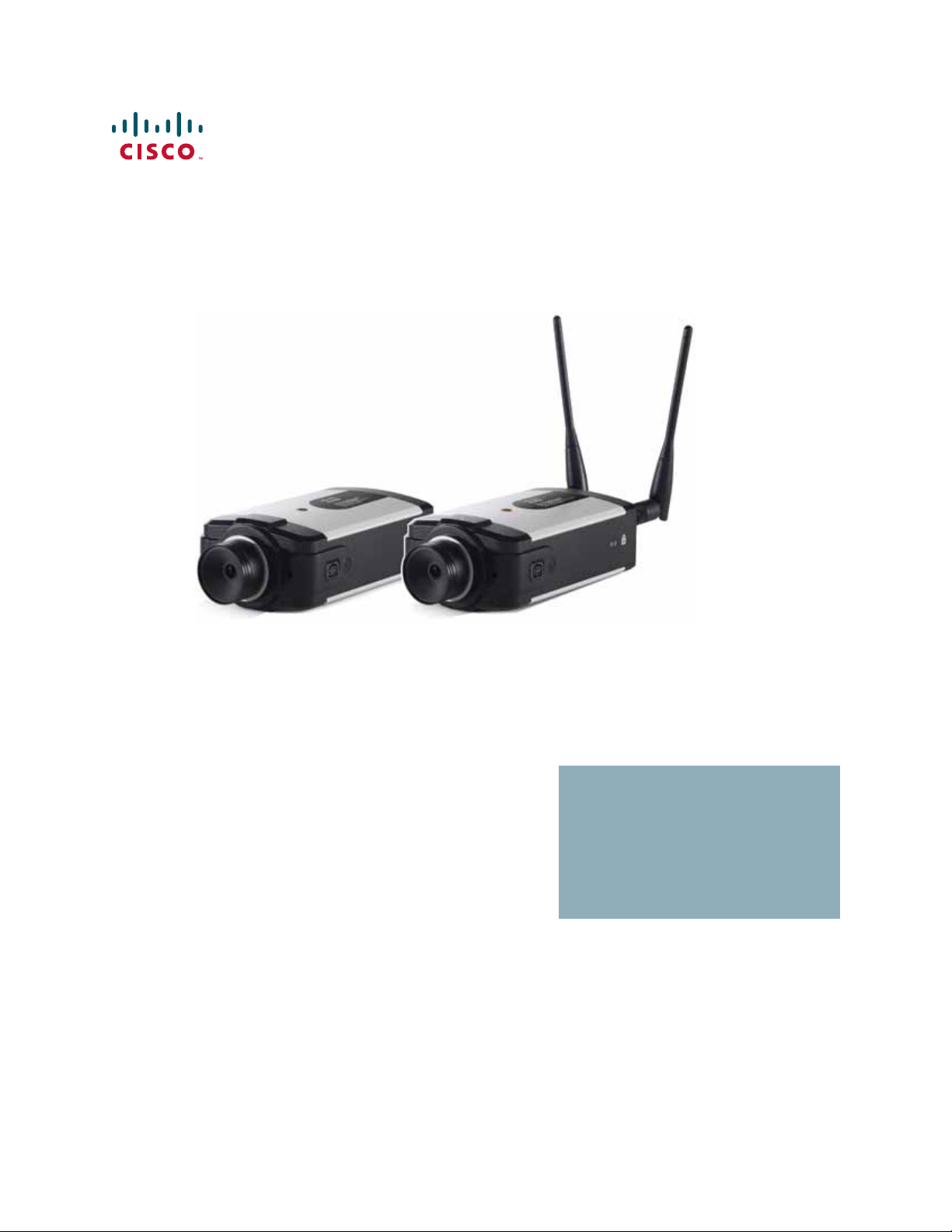
PVC2300 and WVC2300 Internet Video Cameras with
Audio
Page 2

CCDE, CCENT, CCSI, Cisco Eos, Cisco HealthPresence, Cisco Ironport, the Cisco logo, Cisco Lumin, Cisco Nexus, Cisco Nurse Connect, Cisco Stackpower, Cisco StadiumVision,
Cisco TelePresence, Cisco Unified Computing System, Cisco WebEx, DCE, Flip Channels, Flip for Good, Flip Mino, Flip Video, Flip Video (Design), Flipshare (Design), Flip Ultra,
and Welcome to the Human Network are trademarks; Changing the Way We Work, Live, Play, and Learn, Cisco Store, and Flip Gift Card are service marks; and Access Registrar,
Aironet, AsyncOS, Bringing the Meeting To You, Catalyst, CCDA, CCDP, CCIE, CCIP, CCNA, CCNP, CCSP, CCVP, Cisco, the Cisco Certified Internetwork Expert logo,
Cisco IOS, Cisco Press, Cisco Systems, Cisco Systems Capital, the Cisco Systems logo, Cisco Unity, Collaboration Without Limitation, EtherFast, EtherSwitch, Event Center, Fast
Step, Follow Me Browsing, FormShare, G igaDrive, HomeLink, Internet Quotient, IOS, iPhone, iQuick Study, Iro nPort, the IronPort logo, LightStream, Linksys, MediaTone,
MeetingPlace, MeetingPlace Chime Sound, MGX, Networkers, Networking Academy, Network Registrar, PCNow, PIX, PowerPanels, ProConnect, ScriptShare, SenderBase,
SMARTnet, Spectrum Expert, StackWise, The Fastest Way to Increase Your Internet Quotient, TransPath, WebEx, and the WebEx logo are registered trademarks of
Cisco Systems, Inc. and/or its affiliates in the United States and certain other countries.
All other trademarks mentioned in this document or website are the property of their respective owners. The use of the word partner does not imply a partner ship r el at ion ship betw een
Cisco and any other company. (0907R)
© 2009 Cisco Systems, Inc. All rights reserved. OL-20138-02
Page 3

Contents
Chapter 1: Introduction 1
Minimum Requirements 2
Camera Lens Specifications 3
Chapter 2: Planning Your Wireless Network 5
Wireless Network Layout 5
Additional Security Tips 6
Security Threats Facing Wireless Networks 6
Chapter 3: Getting to Know the PVC2300 and WVC2300 Cameras 9
Front Panel 9
Ready LED (Amber) 10
Network LED (Green) 10
Lens 10
Built-in Microphone 10
Back Panel 11
Antenna Connectors 11
Reset 12
Ethernet 12
Activity LED 13
PVC2300 PoE LED 13
Power 14
GPIO 14
Mic In 14
Spkr Out 14
Side Panel 14
Chapter 4: Connecting the Camera 15
Cisco Wired Network 16
Cisco Wireless Network 17
Camera Installation Guidelines 18
Cisco PVC2300 and WVC2300 Internet Video Cameras with Audio Administration Guide i
Page 4

Contents
Camera Hardware Installation 18
Adjusting The Lens 22
Audio Options 23
Chapter 5: Installing the Camera Software 24
Configuring the Basic Camera and Network Settings 24
Setting Up the Wireless Connection on the WVC2300 Camera 28
Wired and Wireless Modes 32
Moving the Camera to Another Network 32
Chapter 6: Upgrading the Camera Firmware 34
Chapter 7: Using the Web-Based Configuration Utility 36
Launching the Web-Based Configuration Utility 36
Home 37
Refresh 38
Setup 38
Connected User 38
Log Out 38
About 38
Help 38
Video Options Icons 39
Setup 41
Chapter 8: Configuring the PVC2300 and WVC2300 Cameras 42
Accessing the Setup Options 43
Setup > Basic Setup 44
Device Settings 44
Network Settings 45
Wireless Settings 46
Setup > Advance Setup 49
Cisco PVC2300 and WVC2300 Internet Video Cameras with Audio Administration Guide ii
Page 5

HTTP/HTTPS 49
RTP/RTSP 49
UPnP 50
Bonjour 51
QoS 51
CoS 51
Contents
Setup > IP Filter 52
IP Filter Settings 52
Administration > Users 53
Administrator 53
Demo 53
User List 53
Administration > Maintenance 54
Restore Factory Defaults 54
Restart 54
Configuration 54
Administration > Firmware 55
Firmware Upgrade 55
Audio/Video > Video 56
MPEG-4 Settings 56
MJPEG Settings 56
Mobile Settings 57
Video Adjustments 57
Options 58
Day/Night Switch 59
Audio/Video > Audio 60
Audio Settings 60
Applications > Mail 62
Primary SMTP Server 62
Secondary SMTP 63
E-mail Setup 64
Cisco PVC2300 and WVC2300 Internet Video Cameras with Audio Administration Guide iii
Page 6

E-mail Body 64
Contents
Applications > FTP 65
Primary FTP 65
Secondary FTP 65
Applications > Instant Messaging 67
Jabber 67
Applications > Motion Detection 68
Applications > Event 70
Event Schedule 70
New Schedule 70
Trigger Event 71
Event Attachment 72
Applications > DDNS 74
DDNS 74
Applications > I/O Ports 75
Input Ports 75
Output Ports State at Power On 75
Output Ports Manual Control 76
Applications > RS-485 77
Port Settings 77
Preset Position 77
Patrol Sequence 78
Applications > SMB/CIFS 81
Status > System 82
Status > Image 82
MPEG-4 82
MJPEG 82
Status > Network 83
Network 83
Wireless 83
Status > Syslog & Log 84
Cisco PVC2300 and WVC2300 Internet Video Cameras with Audio Administration Guide iv
Page 7

Log Type 84
Syslog Server 84
Log List 84
Status > Video Log 85
Video Log 85
Contents
Chapter 9: Sample Configurations 86
Configuring Instant Recording 86
Defining Preset Positions for Patrol Sequence 87
Using Patrol Sequence 88
Configuring E-Mail Alerts 89
Scheduling an Event 91
Configuring Motion Detection Area and Sensitivity 92
Configuring Port Forwarding 94
Setting Security Precautions on the Cisco WVC2300 97
Appendix A: Troubleshooting 98
Questions and Answers 98
Windows Help 101
TCP/IP 101
Shared Resources 101
Network Neighborhood/My Network Places 101
Appendix B: WVC2300 Camera Bandwidth Test 102
Appendix C: Specifications 104
PVC2300 Specifications 104
WVC2300 Specifications 108
I/O Port Specifications 111
Appendix D: Where to Go From Here 114
Cisco PVC2300 and WVC2300 Internet Video Cameras with Audio Administration Guide v
Page 8

Introduction
Thank you for choosing the Cisco Small Business Internet Video Camera with
Audio. This administration guide covers two models.
1
• PVC2300 Business Internet Video Camera with Audio and PoE (Power over
Ethernet)
• WVC2300 Wireless-G Business Internet Video Camera with Audio
For the purpose of this administration guide, whenever a feature applies to both
models, the word camera(s) will be referenced. If a specific model number is
mentioned, then the feature is specific to that model
The Cisco camera surveillance solutions are high quality solutions which can be
optimized for many different applications. The box-type form factor allows these
cameras to be used as-is or put inside an outdoor enclosure for interior or exterior
applications. The cameras use removable CS-mount lenses and can be
customized with Zoom, Wide-Angled, Vari-focal, Auto-Iris (DC type), or other type
of lenses as required for the specific application.
The PVC2300 provides Power over Ethernet (PoE) functionality that facilitates
installation of the PVC2300 in places out of reach of a power outlet.
The cameras can be remotely controlled through an RS-485 interface and
mounted on any PT (pan/tilt) base that supports Pelco-D protocol. The camera
supports 2 input and 2 output connectors which can be used for connecting to an
alarm panel, siren, PIR, smoke detectors, light switch (on/off), door opener, etc.
The cameras incorporate a high quality progressive scan CCD sensor, delivering
good quality undistorted video. The sensor used in the cameras has low light
sensitivity capability. This means that video can be viewed when very low light
(near darkness) is present. Additionally, the cameras incorporate an IR Cut Filter
switcher which, when used with a separate IR lamp, allows for viewing of video in
total darkness.
Cisco PVC2300 and WVC2300 Internet Video Cameras with Audio Administration Guide 1
Page 9

Introduction
Minimum Requirements
1
The cameras support dual CODECs—MPEG-4 and MJPEG. Both CODECs can be
used simultaneously. MPEG-4 gives efficient bandwidth consumption with good
quality compression and is optimal for real-time viewing of video. MJPEG gives
optimal video quality in lossy environments making it ideal for video storage to a
NAS device. Lossy compression is very effective in reducing digital file sizes,
resulting in smaller video file sizes with minor data loss.
The camera’s audio capabilities include 2-way audio, an embedded microphone,
external speaker and microphone ports, and voice compression.
With extensive feature support such as IP Multicast, RTSP, RTP, and 3GPP, video
can be viewed from multiple endpoints and client applications like 3G phones and
Quicktime clients on PCs or Wi-Fi phones.
Support for multiple network protocols like 802.1p priority, 802.1q VLANs, and
Dynamic DNS, make the solution ideal for multiple IP surveillance applications. The
cameras can also be managed securely using HTTPS.
NOTE Before installing a surveillance system, check with local government agencies to
determine if video surveillance and audio monitoring are permitted in your area.
Minimum Requirements
The following tables list the minimum requirements for your PC when monitoring
one camera or up to eight cameras.
Minimum System Requirements (for one camera):
CPU Pentium 4 class, 2 GHz
Memory 512 MB
Operating System Microsoft Windows 2000, XP or Vista
Hard Drive 500 MB of available space
Graphics Card AGP with a minimum 128 MB
Browser Internet Explorer 6.0 (or later) or Mozilla Firefox
Cisco PVC2300 and WVC2300 Internet Video Cameras with Audio Administration Guide 2
Page 10

Introduction
Camera Lens Specifications
NOTE More than eight cameras can be monitored if you reduce the resolution and frame
1
Minimum System Requirements (for up to eight cameras):
CPU Pentium 4 class, 3 GHz dual-core
Memory 1 GB
Operating System Microsoft Windows 2000, XP or Vista
Hard Drive 4 GB of available space
Graphics Card NVidia high performance or equivalent with a minimum 256 MB
Browser Internet Explorer 6.0 (or later) or Mozilla Firefox
rate settings for the video captures. The resolution and video quality can be
adjusted from the Audio/Video > Video window in the web-based utility. See
“Audio/Video > Video” section on page 56.
Camera Lens Specifications
The following lens can be used with the PVC2300 and WVC2300 IP cameras:
Model Number Camera Lens Mount Further
CIVS-IPC-VT38 Tamron 3-8 mm Varifocal Lens CS Go to
CIVS-IPC-VT31 Tamron 3-11 mm Varifocal Lens
CIVS-IPC-VT55 Tamron 5-50 mm Varifocal Lens
CIVS-IPC-VF38 Fujinon 3-8 mm Varifocal Lens
CIVS-IPC-VF31 Fujinon 3-11 mm Varifocal Lens
CIVS-IPC-VF55 Fujinon 5-50 mm Varifocal Lens
CAMLMI Tamron 1/3-inch 3~8 mm Varifocal
2.7X Zoom Lens
CAMLWA Computar 1/3-inch 2.3 mm Wide
Angle Lens
Information
www.cisco.com
/go/surveillance
for acces sory
data sheets and
more
information.
Cisco PVC2300 and WVC2300 Internet Video Cameras with Audio Administration Guide 3
Page 11

Introduction
Camera Lens Specifications
1
For more information about camera accessories, see the Cisco Small Business
Camera Accessories Installation and Administration Guide.
Cisco PVC2300 and WVC2300 Internet Video Cameras with Audio Administration Guide 4
Page 12

Planning Your Wireless Network
A wireless local area network (WLAN) is exactly like a regular local area network
(LAN), except that each computer in the WLAN uses a wireless device to connect
to the network. Computers and other devices, such as peripherals, in a WLAN
share the same frequency channel and SSID, which is an identification name for
wireless devices. This chapter includes the following sections:
• Wireless Network Layout, page 5
2
• Additional Security Tips, page 6
• Security Threats Facing Wireless Networks, page 6
Wireless Network Layout
The WVC2300 camera is compatible with 802.11g routers, such as model number
WRVS4400N, as well as 802.11g access points, including model number
WAP4410N. The camera can also communicate with network adapters, such as
the Wireless-G Notebook Adapter (model number WPC4400N) for your laptop
computers, Wireless-G PCI Adapter (model numbers WMP200) for your desktop
PCs, and Wireless-G USB Adapter (model number WUSB200) for your computers
that connect to the wireless network through USB modems.
With these, and many other Cisco products, your networking options are limitless.
Go to the Cisco website at www.cisco.com for more information about Cisco
products.
NOTE Your wireless range is variable and depends on your environment.
Cisco PVC2300 and WVC2300 Internet Video Cameras with Audio Administration Guide 5
Page 13

Planning Your Wireless Network
Additional Security Tips
Additional Security Tips
• Keep wireless routers, access points, or gateways away from exterior walls
and windows.
• Turn wireless routers, access points, or gateways off when they are not
being used (at night, during vacations).
• Use strong passphrases that are at least eight characters in length.
Combine letters and numbers to avoid using standard words that can be
found in the dictionary.
Security Threats Facing Wireless Networks
2
Cisco wants to make wireless networking as safe and easy for you as possible.
The current generation of Cisco products provide several network security
features, but they require specific action on your part for implementation. So, keep
the following suggestions in mind whenever you are setting up or using your
wireless network. Also, see “Setting Security Precautions on the Cisco
WVC2300” on page 97.
Wireless networks are easy to find. Hackers know that in order to join a wireless
network, wireless networking products first listen for “beacon messages.” These
messages can be easily decrypted and contain much of the network’s information,
such as the network’s SSID (Service Set Identifier). Here are the steps you can
take to prevent intruders:
Change the administrator’s password regularly. With every wireless networking
device you use, keep in mind that network settings (SSID, WEP keys, etc.) are
stored in its firmware. Your network administrator is the only person who can
change network settings. If a hacker learns the administrator’s password, he, too,
can change those settings. So, make it harder for a hacker to get that information.
Change the administrator’s password regularly.
SSID. There are several things to keep in mind about the SSID:
• Do not broadcast it
• Make it unique
• Change it often
Cisco PVC2300 and WVC2300 Internet Video Cameras with Audio Administration Guide 6
Page 14

Planning Your Wireless Network
Security Threats Facing Wireless Networks
Most wireless networking devices will give you the option of broadcasting the
SSID. While this option may be more convenient, it allows anyone to log into your
wireless network. This includes hackers. So, don’t broadcast the SSID.
Wireless networking products come with a default SSID set from the factory. (The
Cisco default SSID is “ciscosb”.) Hackers know these defaults and can check
these against your network. Change your SSID to something unique and not
something related to your company or the networking products you use.
Change your SSID regularly so that any hackers who have gained access to your
wireless network will have to start from the beginning in trying to break in.
MAC Addresses. Enable MAC Address filtering. MAC Address filtering allows you
to provide access to only those wireless nodes with certain MAC Addresses. This
makes it harder for a hacker to access your network with a random MAC Address.
WEP Encryption. Wired Equivalent Privacy (WEP) is often looked upon as a cure-all
for wireless security concerns. This is overstating WEP’s ability. Again, this can
only provide enough security to make a hacker’s job more difficult. There are
several ways that WEP can be maximized:
2
• Use the highest level of encryption possible
• Use “Shared Key” authentication
• Change your WEP key regularly
WPA/WPA2 Personal. WPA stands for Wi-Fi Protected Access, which is a security
standard stronger than WEP encryption. A network encrypted with WPA/WPA2 is
more secure than a network encrypted with WEP, because WPA/WPA2 uses
dynamic key encryption. To protect the information as it passes over the airwaves,
you should enable the highest level.
WPA/WPA Enterprise. Enterprise refers to using RADIUS server for authentication,
while RADIUS stands for Remote Authentication Dial-In User Service. This type of
authentication requires some advanced expertise because it involves setting up a
RADIUS server for authentication and, in some cases, creation of certificates for
both the RADIUS server and the camera.
If you are using WPA/WPA2 Enterprise security, you will need to upload security
certificates to the camera. Certificates must be in the following format:
• Root certificate: DER encoded binary x.509 (CER/PEM)
• User certificate: Personal Information Exchange (PKCS#12(.PFX))
Cisco PVC2300 and WVC2300 Internet Video Cameras with Audio Administration Guide 7
Page 15

Planning Your Wireless Network
!
Security Threats Facing Wireless Networks
Implementing encryption may have a negative impact on your network’s
performance, but if you are transmitting sensitive data over your network,
encryption should be used.
These security recommendations should help keep your mind at ease while you
are enjoying the most flexible and convenient technology Cisco has to offer.
CAUTION Always remember that each device in your wireless network MUST use the same
encryption method and encryption key or your wireless network will not function
properly.
2
Cisco PVC2300 and WVC2300 Internet Video Cameras with Audio Administration Guide 8
Page 16
3
Getting to Know the PVC2300 and WVC2300 Cameras
This chapter describes the external features of the Cisco PVC2300 and WVC2300
Internet Video Cameras and includes the following sections:
• Front Panel, page 9
• Back Panel, page11
Front Panel
• Side Panel, page14
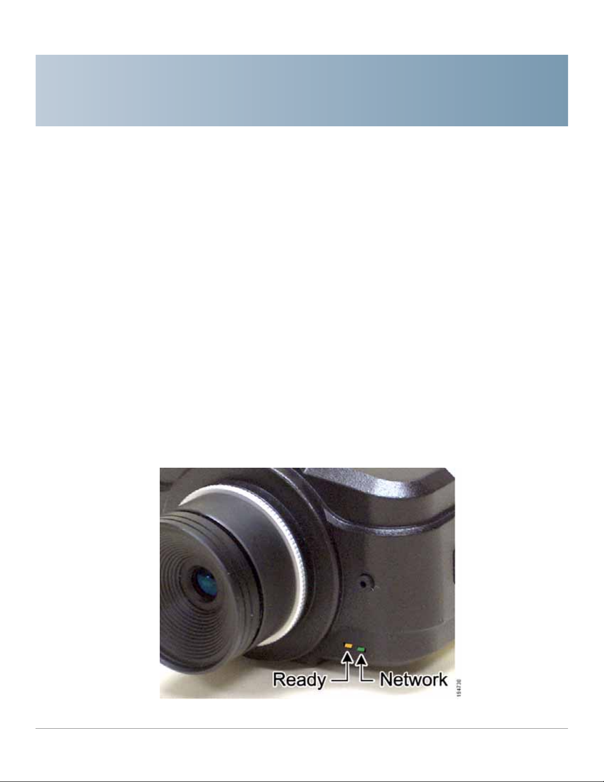
The LEDs, camera lens, and built-in microphone are located on the front panel of
the camera.
Cisco PVC2300 and WVC2300 Internet Video Cameras with Audio Administration Guide 9
Page 17

Getting to Know the PVC2300 and WVC2300 Cameras
Front Panel
Ready LED (Amber)
The Ready LED has the following states:
• Off—Camera is powered off.
• On—Camera is powered on.
• Flashing—The Ready LED will flash during start up. This will take 15 to 20
seconds.
Network LED (Green)
The Network LED has the following states:
• Off—Network connection not detected.
3
• On—Network connection detected.
• Flashing—Sending/receiving data.
Lens
The camera includes a removable CS-mount lens.
• For specifications on the included lens, refer to Appendix C,
“Specifications.”
• For a list of recommended lenses to use with this camera, see “Camera
Lens Specifications” on page 3. Also, refer to the Cisco Small Business
Camera Accessories Installation and Administration Guide.
Built-in Microphone
There is a built-in microphone mounted on the front of the camera. The camera
also has a connection for an external microphone on the rear. Connecting an
external microphone will disable the built-in microphone.
Cisco PVC2300 and WVC2300 Internet Video Cameras with Audio Administration Guide 10
Page 18
Getting to Know the PVC2300 and WVC2300 Cameras
Back Panel
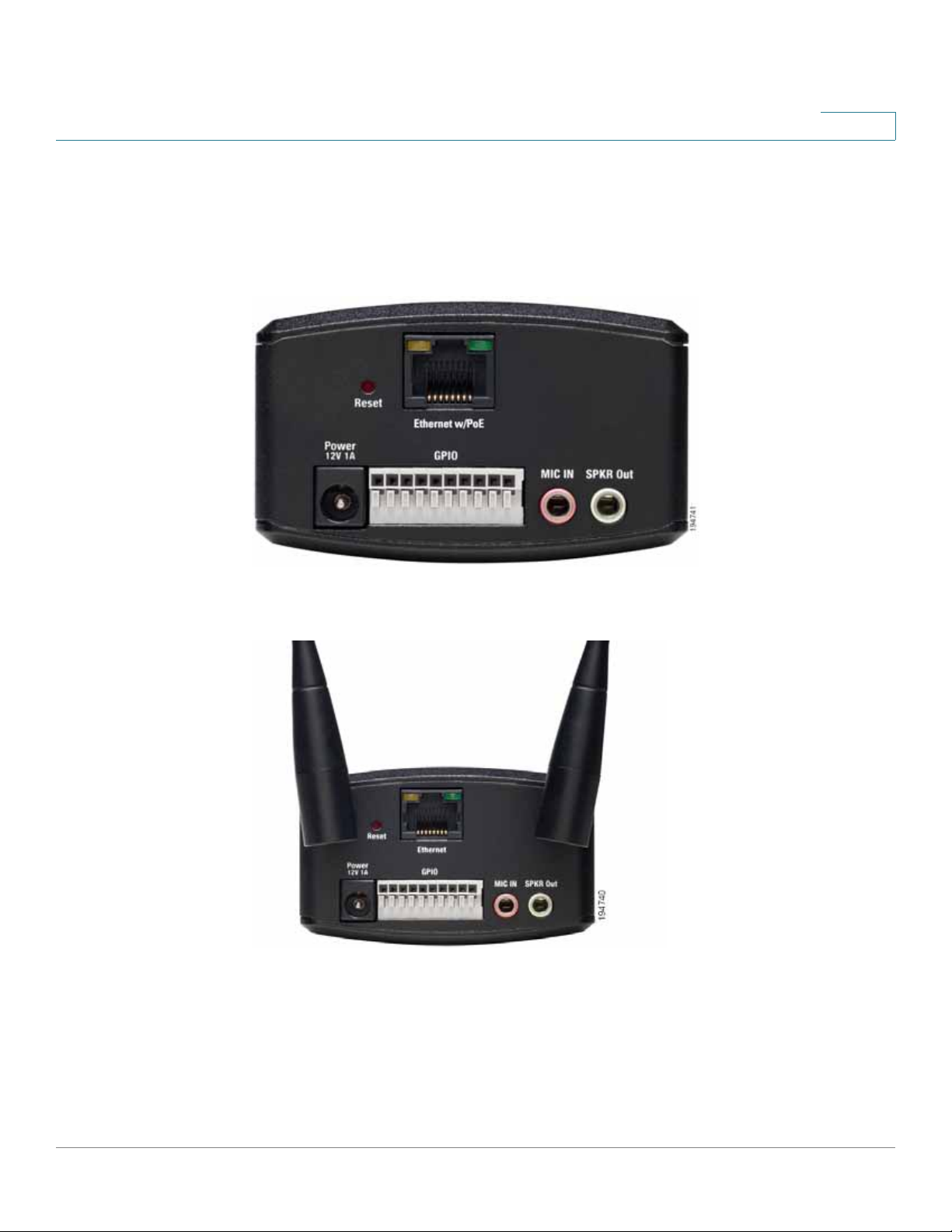
Back Panel
The ports and reset button are located on the back panel of the camera.The
following shows the back panel of the PVC2300.
3
The following shows the back panel of the WVC2300.
Antenna Connectors
Antenna connectors are only found on the WVC2300 camera. The connectors are
used to attach the antennas to the device for wireless connectivity.
Cisco PVC2300 and WVC2300 Internet Video Cameras with Audio Administration Guide 11
Page 19

Getting to Know the PVC2300 and WVC2300 Cameras
Back Panel
Reset
The reset button can be accessed with a straightened paper clip or similar object.
The reset button has two functions:
• Restore Factory Defaults—To restore the factory default settings, press
the Reset button for more than 10 seconds. When you let go of the button,
the LEDs on the front of the camera will flash and then return to a normal
state when the camera is ready.
• Set Static IP Address—By default the camera is set to receive an IP
address from a DHCP server. If you do not have a DHCP server on your
network, you can set a static IP address by pressing the Reset button on the
camera for less than 10 seconds. A default IP address of 192.168.1.99 will
be assigned to the camera. This information also can set in the Setup
Wizard and in the web-based configuration utility for the camera.
3
Tips when using the default IP address:
• If the camera is connected directly to your computer, then your computer
needs to be on the same subnet as the default IP address in order to access
the configuration utility.
• If you are using a router, you may be on a different subnet such as
192.168.2.1.
Ethernet
The Ethernet port supports network speeds of either 10 Mbps or 100 Mbps, and
can operate in half and full-duplex mode.
Auto-sensing technology enables the port to automatically detect the speed of the
device connected to it (10 Mbps or 100 Mbps), and adjust its speed and duplex
accordingly.
The Ethernet port supports automatic MDI/MDI-X operation, so you can use
straight-through or crossover cables to connect to PCs, servers, or switches.
NOTE NOTE FOR PVC2300: The PVC2300 camera’s Ethernet port also supports the IEEE
802.3af Power-over-Ethernet (PoE) standard that enables DC power to be supplied
to the camera using wires in the connecting twisted-pair cable. Any 802.3afcompliant device attached to the port can directly supply power to the camera
Cisco PVC2300 and WVC2300 Internet Video Cameras with Audio Administration Guide 12
Page 20

Getting to Know the PVC2300 and WVC2300 Cameras
Back Panel
over the twisted-pair cable without requiring its own separate power source. This
capability gives network administrators centralized power control, which
translates into greater network availability.
To connect a device to the port, you will need to use Category 5 (or better)
network cable.
NOTE NOTE FOR WVC2300: Attaching an Ethernet cable will disable the wireless
interface on the WVC2300 camera. Only one interface can be active at any time.
NOTE NOTE FOR WVC2300: On the WVC2300 camera, the Ethernet cable should only be
connected or disconnected when the camera is powered OFF. Attaching or
detaching the Ethernet cable while the camera is powered on does NOT switch the
interface between wired and wireless. In order to switch from wired to wireless or
vice versa, the power needs to be disconnected and reconnected to change from
one mode to the other. Disconnecting the Ethernet while power is on will merely
disconnect the camera from the network.
3
Activity LED
The Activity LED flashes when activity is detected on the Ethernet port.
PVC2300 PoE LED
This LED only functions on the PVC2300 camera. The LED has the following states:
• On—PoE connection is detected.
• Off—PoE connection is not detected.
On the back panel, the green LED is the PoE indicator and when on, indicates that
you have PoE power. If you plug in the power supply, this LED will not light up.
Another good indicator is if you happen to plug in both the PoE and regular power
supply, if the green LED is on, this indicates you have PoE power and if not, it
indicates you have lost power from your PoE switch.
Cisco PVC2300 and WVC2300 Internet Video Cameras with Audio Administration Guide 13
Page 21
Getting to Know the PVC2300 and WVC2300 Cameras
Side Panel
Power
The Power port is where you will connect the power adapter.
NOTE NOTE FOR PVC2300: The Power port is automatically turned off if a PoE connection
is detected on the Ethernet port.
GPIO
This port is utilized for I/O connections. Detailed specifications can be found in the
Specifications section of this Administration Guide.
3
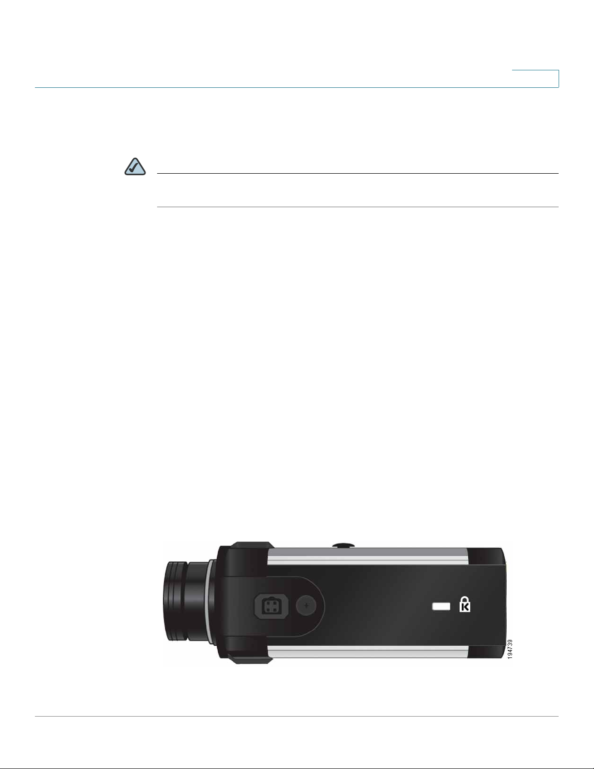
Side Panel
Mic In
This jack is used to connect an external microphone to the camera.
Spkr Out
This jack is used to connect powered speakers to the camera.
The security slot is located on a side panel of the camera and can be used to
attach a Kensington lock.
Cisco PVC2300 and WVC2300 Internet Video Cameras with Audio Administration Guide 14
Page 22

Connecting the Camera
This chapter will guide you through the hardware installation for the Cisco
PVC2300 and WVC2300 Internet Video Cameras. There are procedures for
installing the camera into a wired or wireless network. The following sections are
included:
• Cisco Wired Network, page16
• Cisco Wireless Network, page17
4
• Camera Installation Guidelines, page18
• Camera Hardware Installation, page18
• Adjusting The Lens, page 22
• Audio Options, page 23
Cisco PVC2300 and WVC2300 Internet Video Cameras with Audio Administration Guide 15
Page 23
Connecting the Camera
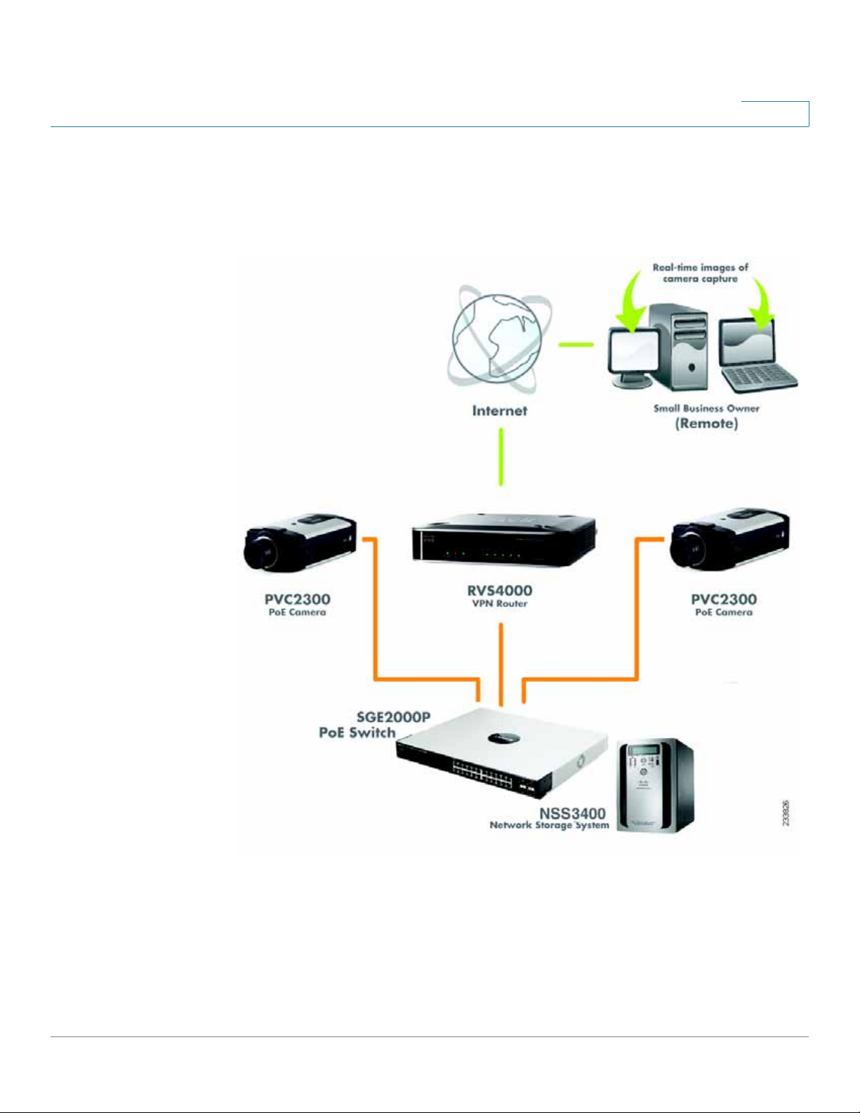
Cisco Wired Network
Cisco Wired Network
The following illustration provides an example of a Cisco wired network:
4
Cisco PVC2300 and WVC2300 Internet Video Cameras with Audio Administration Guide 16
Page 24
Connecting the Camera
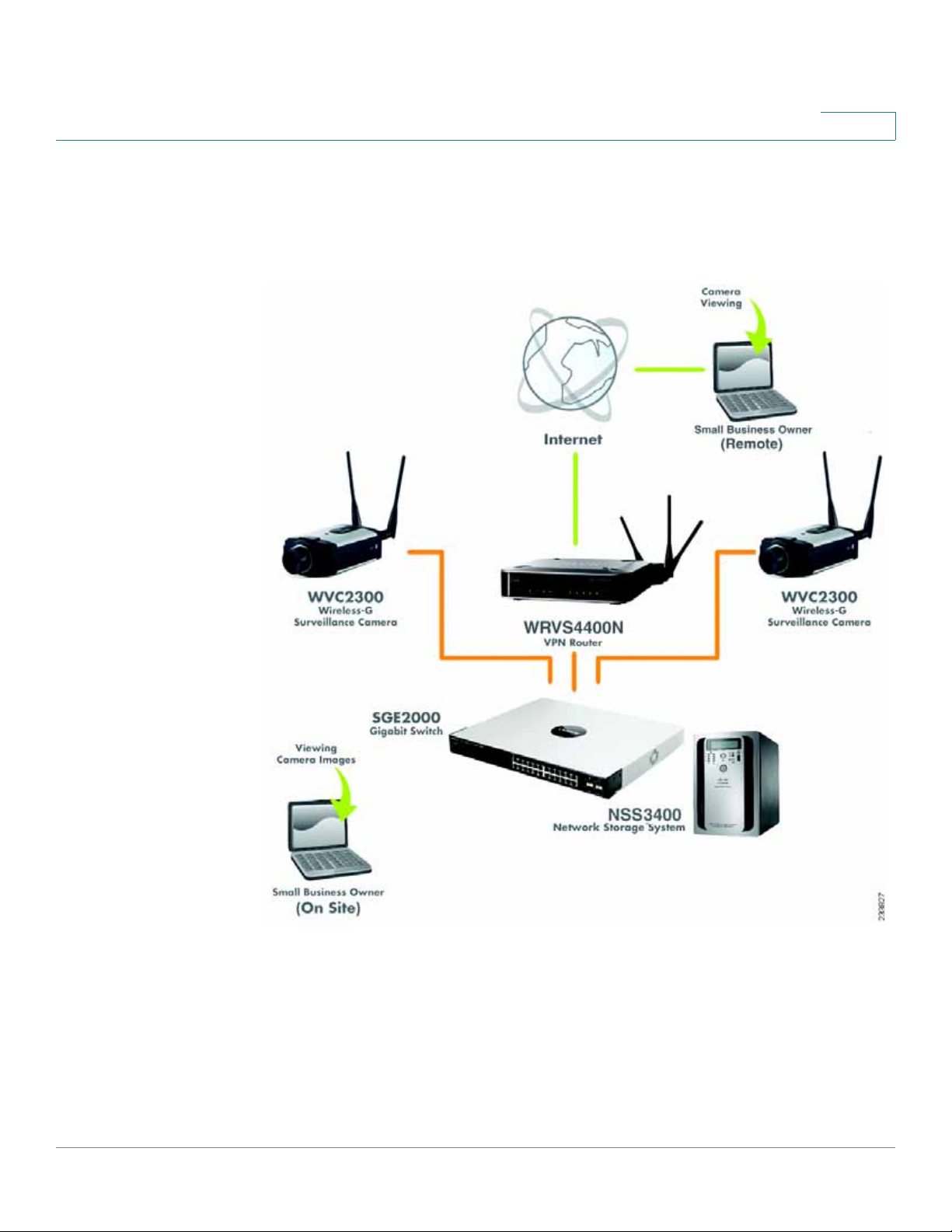
Cisco Wireless Network
Cisco Wireless Network
The following illustration provides an example of a Cisco wireless network:
4
Cisco PVC2300 and WVC2300 Internet Video Cameras with Audio Administration Guide 17
Page 25

Connecting the Camera
Camera Install ation Guidelines
Camera Installation Guidelines
Consider the following guidelines before installing and mounting your cameras.
While the motion detection window and the degree of sensitivity can be optimized
later, it is best to optimize your camera location first.
• Choose a location that provides adequate coverage of the area to be
monitored.
• If using the microphone in the camera, note that the cameras are designed
to pick up audio from a distance (unlike a web camera that you would place
near you.)
• If using an external microphone or speaker, place the microphone far
enough away from the speaker to avoid feedback. The volume of the
speaker and the background noise of the environment will determine the
exact distance, possibly up to one yard (one meter) away.
4
• Cameras mounted outdoors should be installed in an IP66-certified
enclosure to protect the camera from the elements, while maintaining
acceptable operating temperatures. If an enclosure is used, an external
microphone is required for audio.
• If using motion detection, consider potential sources of false positives, such
as trees and shrubs, drastic light changes, wandering animals, and traffic.
Camera Hardware Installation
Follow these steps to install the PVC2300 or WVC2300 camera:
NOTE Before attaching the camera extension or swivel head, the stand base can be
mounted in a permanent location by using three screws to secure the stand base
to the desired location.
STEP1 (Optional) Attach the base of the camera stand to a permanent location by using
three screws.
Cisco PVC2300 and WVC2300 Internet Video Cameras with Audio Administration Guide 18
Page 26
Connecting the Camera
Camera Hardware Installation
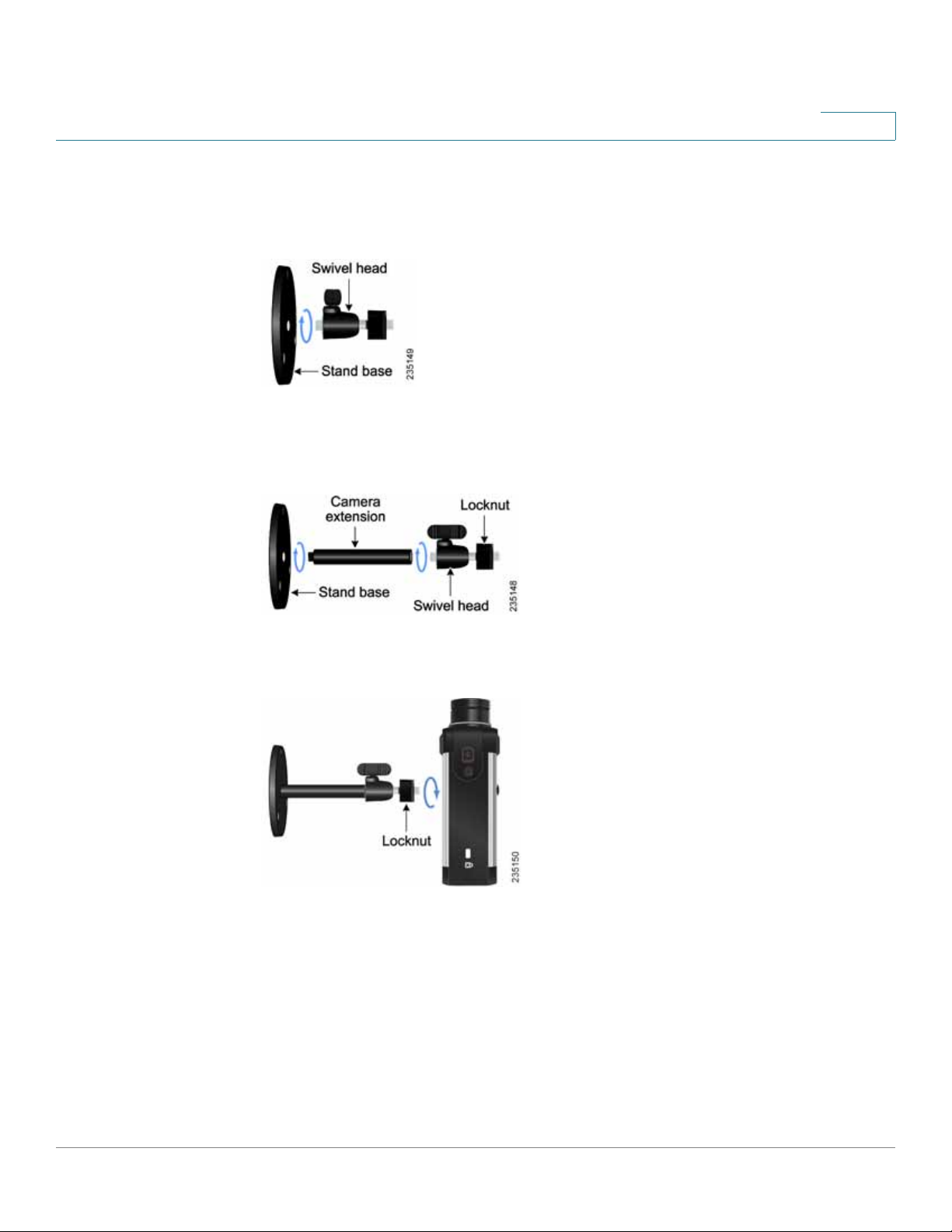
STEP 2 Assemble the camera stand in one of the following ways:
4
• Attach the swivel head directly to the stand base.
• If an extension is necessary, attach the camera extension to the stand base
and then attach the swivel head to the extension.
STEP 3 Connect the camera stand to the bottom of the camera.
STEP 4 Adjust the camera to the appropriate viewing position and secure the camera in
place by tightening the locknut.
Cisco PVC2300 and WVC2300 Internet Video Cameras with Audio Administration Guide 19
Page 27
Connecting the Camera
Camera Hardware Installation
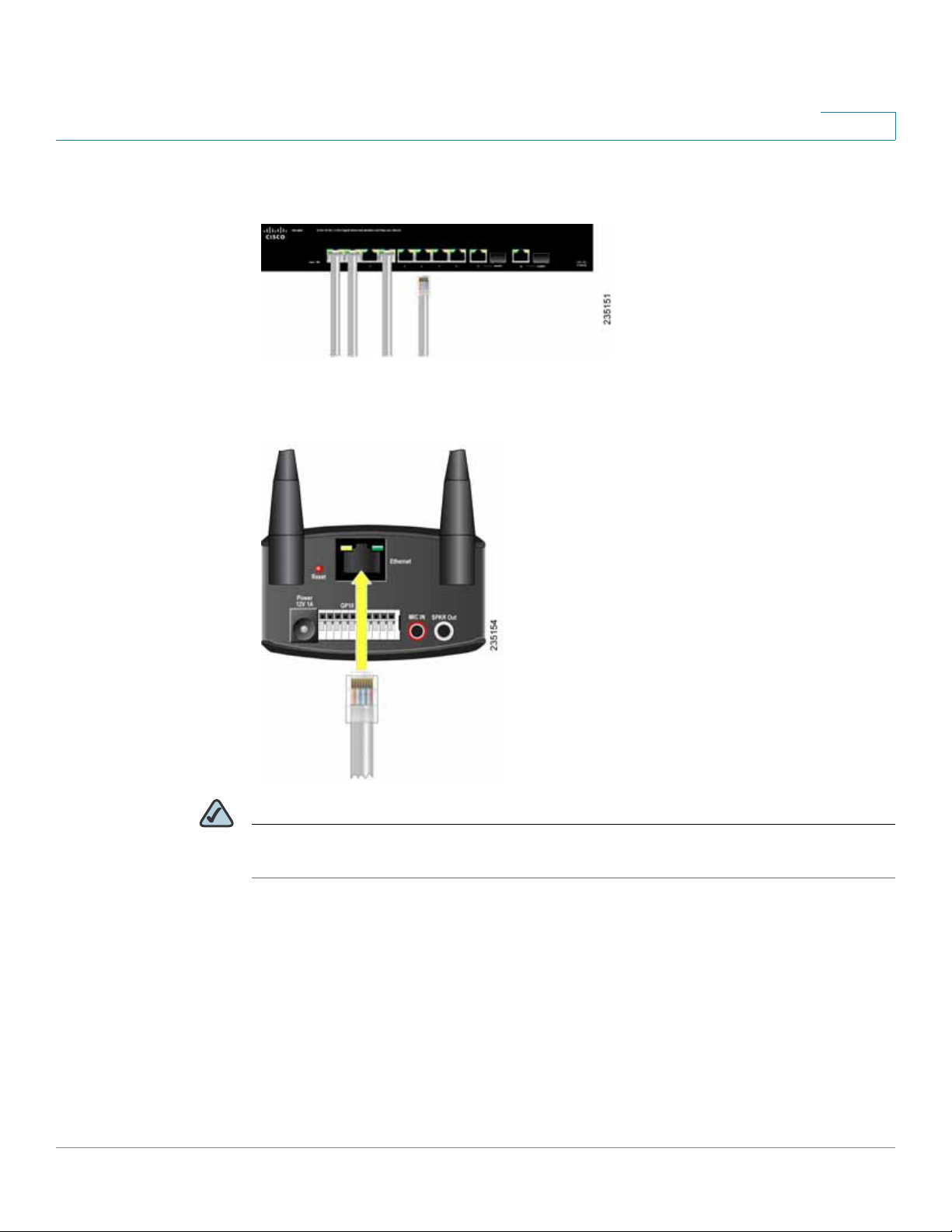
STEP 5 Connect the included Ethernet network cable to your network router or switch.
STEP 6 Connect the other end of the cable to the camera Ethernet port.
4
NOTE If your network switch provides Power over Ethernet (PoE), proceed to step 8. If you
are not sure if the switch provides PoE, refer to the switch documentation.
Cisco PVC2300 and WVC2300 Internet Video Cameras with Audio Administration Guide 20
Page 28
Connecting the Camera
Camera Hardware Installation
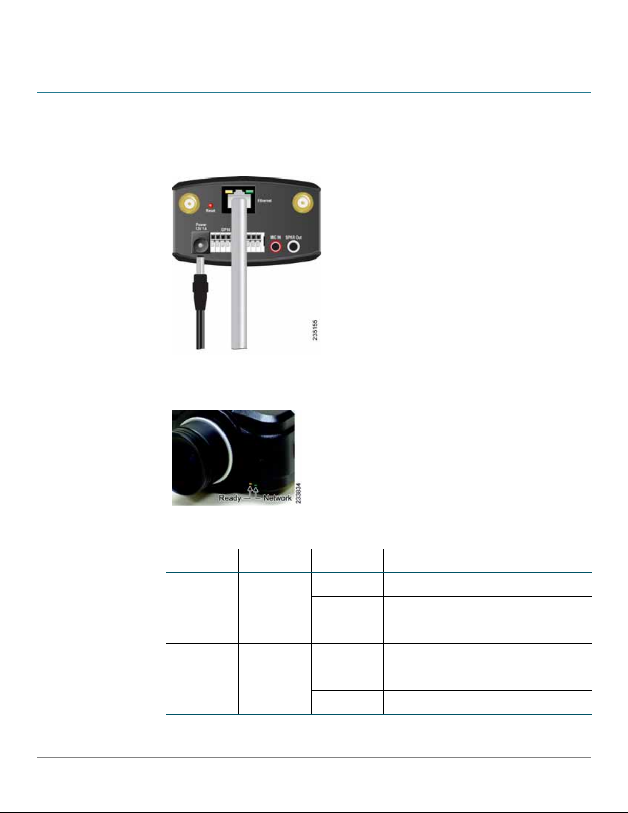
STEP 7 If your network switch does not provide PoE, connect the included power adapter
4
to the Power port of the camera and insert the other end into a standard electrical
outlet.
STEP 8 Verify that the camera LEDs are lit.
LED Color Activity Action
Ready Amber Off
On Camera is powered on.
Blink Camera is booting.
Network Green Off Network connection not detected.
Camera is powered off.
On Network connection detected.
Blink Sending and receiving data.
Cisco PVC2300 and WVC2300 Internet Video Cameras with Audio Administration Guide 21
Page 29
Connecting the Camera
Adjusting The Lens
NOTE If you are installing the PVC2300 camera, you are done with the camera installation.
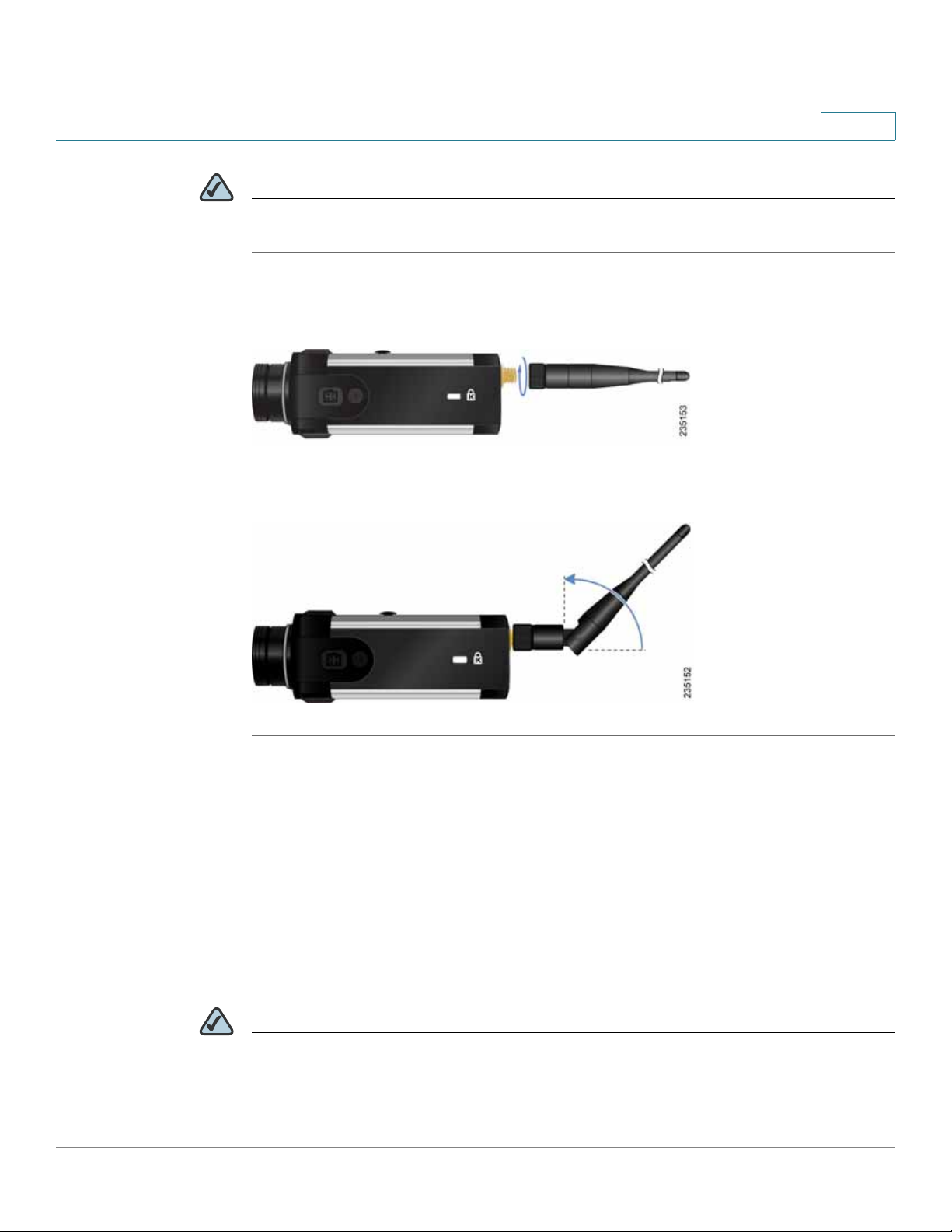
STEP 9 Connect each of the two antennas to the antenna connectors on the back of the
STEP 10 Place the antennas in an upright position.
4
However, if you are installing the WVC2300 camera, proceed to the next step.
camera.
Congratulations! You have completed the camera hardware installation. Continue
with Chapter 5, “Installing the Camera Software.”
Adjusting The Lens
The PVC2300 and WVC2300 Internet Cameras use an adjustable CS mount lens.
Adjust the focus by slowly rotating the camera Lens Focus clockwise or
counterclockwise.
NOTE The resolution and video quality can be adjusted from the Audio/Video > Video
window in the web-based utility. See “ Audio/Video > Video” section on page 56.
Use the camera Lens Focus to fine tune the image.
Cisco PVC2300 and WVC2300 Internet Video Cameras with Audio Administration Guide 22
Page 30

Connecting the Camera
Audio Options
Audio Options
NOTE The microphone you use must have its own source of power, like your computer
STEP 1 Connect the 3.5 mm input jack of your microphone to the MIC IN port on the
STEP 2 Place the external microphone in an appropriate location.
4
To use your own microphone instead of the camera’s built-in microphone, follow
these steps:
speakers.
camera’s back panel. The built-in microphone will automatically be disabled.
To use an optional external speaker with the camera, follow these steps:
NOTE The speakers need to be “powered” speakers, like your computer speakers.
STEP 1 Connect the 3.5 mm jack of your speaker to the SPKR OUT port on the camera’s
back panel.
STEP 2 Place the external speaker in an appropriate location.
Cisco PVC2300 and WVC2300 Internet Video Cameras with Audio Administration Guide 23
Page 31

Installing the Camera Software
This chapter describes installing the Cisco PVC2300 and WVC2300 Internet
Video Camera software and setting up the wireless connection on the WVC2300
camera. The following sections are included:
• Configuring the Basic Camera and Network Settings, page 24
• Setting Up the Wireless Connection on the WVC2300 Camera, page 28
5
• Wired and Wireless Modes, page 32
• Moving the Camera to Another Network, page 32
Configuring the Basic Camera and Network Settings
The Cisco PVC2300 and WVC2300 Internet Cameras can be set up using the
Setup Wizard that is included on the product CD. There are two ways to use the
Setup Wizard:
1. Launch the Setup Wizard from the CD. Launching from the CD is useful if you do
not want to install the software on your computer.
2. Install the software on your computer. This is useful if you want to install more
cameras in the future and don’t want to search for the CD.
NOTE Microsoft Internet Explorer (IE) is the supported browser for the PVC2300 and
WVC2300 cameras.
NOTE If the Setup Wizard does not find your Cisco PVC2300 or WVC2300 camera,
enable Universal Plug and Play (UPnP) on you computer. See the instructions for
enabling UPnP in Appendix A, “Troubleshooting.”
Cisco PVC2300 and WVC2300 Internet Video Cameras with Audio Administration Guide 24
Page 32

Installing the Camera Software
Configuring the Basic Camera and Network Settings
To configure basic camera and network settings, follow these steps:
STEP 1 Insert the Setup CD into your CD-ROM drive. If the CD doesn’t run automatically, go
to My Computer and click on your CD-ROM drive.
STEP 2 The Welcome window appears. Click Start.
STEP 3 The License Agreement window appears. Click Next if you agree.
STEP 4 The Wizard searches your network for your camera and displays a list of all
cameras found. From the Camera Discovery window, highlight the camera you
want to configure and click Next. If the camera you want to configure is not
displayed in the Selection box, enable UPnP on your computer as described in
Appendix A, “Troubleshooting” and click Search Again.
STEP 5 When prompted, type admin in both the Administrator Name and Administrator
Password fields. The default user name and password is admin. Click OK.
5
NOTE For security purposes, it is recommended that you change the password using the
camera’s web-based utility at a later time. See “ Administration > Users” on page
53.
STEP 6 From the Basic Settings window, configure the following settings:
• Camera Name—Enter a unique name for the camera, up to 16 characters in
length. Unique names are helpful when you are using multiple cameras on
the same network.
• Description—Enter a description, up to 32 characters in length, with
additional information such as the location of the camera.
• Time Zone—Select the time zone that corresponds with the camera’s
location.
• Date—Enter the current date. This sets the camera’s calendar date and the
information is used when the date stamp is referenced in the image
captures.
• Time—Enter the current time. This sets the camera’s clock and is used
when the time stamp is referenced in the image captures.
You have completed identifying the camera and configuring the basic settings.
STEP 7 Click Next to continue and configure the network settings.
Cisco PVC2300 and WVC2300 Internet Video Cameras with Audio Administration Guide 25
Page 33

Installing the Camera Software
Configuring the Basic Camera and Network Settings
STEP 8 In the Network Settings window, select Static IP address from the drop-down list
if you want to assign the IP address. Otherwise, leave the default setting as Obtain
An IP Address Automatically (DHCP) and click Next.
STEP 9 The current settings of the camera are displayed. Make any changes needed for
your network and click Next.
STEP10 From the Review Camera Settings window, click Next to confirm the settings or
click Back to make changes.
STEP 11 From the Confirm Settings window, click OK to continue or Cancel to close the
Confirm Settings window. When Cancel is clicked, you can click Back to make
changes.
When OK is clicked, the new settings are saved.
STEP 12 A dialog box appears indicating that the configuration has been saved
successfully. Click OK to continue.
5
STEP 13 Congratulations! Your camera is now configured. Click Finish to complete the
process.
The PVC2300 or WVC2300 Internet Camera Home window launches.
STEP 14 When prompted, enter admin in both the User name and Password fields on the
login window. The default username and password is admin.
Cisco PVC2300 and WVC2300 Internet Video Cameras with Audio Administration Guide 26
Page 34

Installing the Camera Software
Configuring the Basic Camera and Network Settings
STEP 15 Internet Explorer prompts you to install ActiveX. In order to view video, you must
accept the ActiveX.
After installing ActiveX, the home window displays.
5
Cisco PVC2300 and WVC2300 Internet Video Cameras with Audio Administration Guide 27
Page 35

Installing the Camera Software
Setting Up the Wireless Connection on the WVC2300 Camera
5
Setting Up the Wireless Connection on the WVC2300 Camera
To configure the WVC2300 camera for wireless connectivity, follow these steps:
STEP1 Click Setup in the toolbar to open the Setup > Basic Setup
STEP 2 Enter the appropriate Wireless Settings:
• SSID—The SSID is the network name shared among all devices in a
wireless network. Enter the network’s SSID or network name here. The
SSID is case sensitive. Default is ciscosb.
• Security—Click Edit Security Settings to display the Wireless Security
window.
STEP 3 From the Wireless Security window, select the drop-down list from Security Mode
to select the appropriate option based on your wireless network configuration:
- Disabled—No security is implemented on your wireless network. Data
is not encrypted before transmission.
- WEP—WEP is a basic encryption method that is not as secure as later
methods such as WPA-Personal or WPA2 Personal. However, it is
supported by all clients.
- WP A /WP A2 Personal—Offers two encryption methods, TKIP and AES,
with dynamic encryption keys.
window.
- WPA /WPA2 Enterprise—Requires that your LAN has a RADIUS server
for authentication.
The following describes the settings for each Security Mode option.
WEP
• TX Key—Select the number of the key used for the wireless network.
• WEP Encryption—Select the appropriate option for key length based on
your network settings.
• Passphrase—Type in the passphrase used to generate WEP keys for your
network and click Generate.
• Key 1-4—Key values can be entered in manually or generated from a
passphrase.
Cisco PVC2300 and WVC2300 Internet Video Cameras with Audio Administration Guide 28
Page 36

Installing the Camera Software
Setting Up the Wireless Connection on the WVC2300 Camera
• Authentication—Select the appropriate authentication type used on the
wireless network.
WPA /WPA2 Personal
• Encryption—This cannot be modified.
• Shared Key—Enter the shared key used for accessing the wireless
network.
WPA /WPA2 Enterprise
The options vary depending on the protocol type selected.
• Protocol Type—Select EAP-TLS or EAP-TTLS.
EAP-TLS
5
• User ID—The user ID used to login to your RADIUS server.
• Root CA—A root certificate is an unsigned public key certificate or a self-
signed certificate, which implies that you trust your browser’s publisher to
include correct root certificates and in turn the certificate authorities it trusts,
and anyone to whom the CA may have issued a certificate-issuing-certificate,
to faithfully authenticate the users of all their certificates.
• User CA—A user certificate is a signed private key certificate, which implies
that you trust your browser’s publisher to include correct user certificates and
in turn the certificate authorities it trusts, and anyone to whom the CA may have
issued a certificate-issuing-certificate, to faithfully authenticate the users of all
their certificates.
• Password—This is for this camera’s client login to the RADIUS server and must
match the key stored on the RADIUS server.
EAP-TTLS
• Process Me th od—Choose an authentication method as required to handle the
processing and transmitting of CA to your RADIUS server.
• User ID—The user ID used for login to your RADIUS server.
• Password—This is for this camera’s client login to the RADIUS server.
• Anonymous ID—The unsigned public ID used for login to your RADIUS server.
• Root CA—A root certificate is an unsigned public key certificate or a self-
signed certificate, which implies that you trust your browser’s publisher to
Cisco PVC2300 and WVC2300 Internet Video Cameras with Audio Administration Guide 29
Page 37

Installing the Camera Software
Setting Up the Wireless Connection on the WVC2300 Camera
include correct root certificates and in turn the certificate authorities it trusts,
and anyone to whom the CA may have issued a certificate-issuing-certificate,
to faithfully authenticate the users of all their certificates.
STEP 4 Click Save to save the wireless security settings and close the window.
STEP 5 From the Setup > Basic Setup window, click Save to save the wireless settings.
STEP 6 Disconnect the power to the camera.
5
STEP 7 Disconnect the Ethernet cable from the camera.
Cisco PVC2300 and WVC2300 Internet Video Cameras with Audio Administration Guide 30
Page 38

Installing the Camera Software
Setting Up the Wireless Connection on the WVC2300 Camera
NOTE The wireless connection will not work if an Ethernet cable is attached to the camera
when it is powered on.
STEP 8 Reconnect the power to the camera.
STEP 9 Click Home in the toolbar to verify the video is streaming from your wireless
connection. You should be able to view video on the Home window.
5
Cisco PVC2300 and WVC2300 Internet Video Cameras with Audio Administration Guide 31
Page 39

Installing the Camera Software
Wired and Wireless Mode s
Wired and Wireless Modes
NOTE This section applies to the Cisco WVC2300 camera.
After the initial configuration, you can use the camera in one of two modes: wired
or wireless. Verify the mode you are in by viewing the LEDs. You cannot use the
camera in both modes simultaneously.
To switch between wired and wireless modes, see “Moving the Camera to
Another Network” on page 32.
Moving the Camera to Another Network
5
NOTE This section applies to the Cisco WVC2300 camera.
When you move the camera from a wired network to a wireless network, or vice
versa, you must power off the camera before connecting to the new network.
To move the camera from a wired network to a wireless network, follow these
steps:
STEP 1 Unplug the power adapter from the camera.
STEP 2 Unplug the Ethernet network cable from the camera.
STEP 3 Re-connect the power adapter to the Power port on the camera. The camera’s
Ready LED flashes while the camera is initializing. The camera is ready for use
when the Ready and Network LEDs are solidly lit.
Cisco PVC2300 and WVC2300 Internet Video Cameras with Audio Administration Guide 32
Page 40

Installing the Camera Software
Moving the Camera to Another Network
To move the camera from a wireless network to a wired network, follow these
steps:
STEP 1 Unplug the power adapter from the camera.
STEP 2 Connect the Ethernet network cable to your PC, router, or switch.
STEP 3 Connect the other end of the cable to the Ethernet port on the camera.
STEP 4 Re-connect the power adapter to the Power port on the camera. The camera’s
Ready LED flashes while the camera is initializing. The camera is ready for use
when the Ready and Network LEDs are solidly lit.
5
Cisco PVC2300 and WVC2300 Internet Video Cameras with Audio Administration Guide 33
Page 41

Upgrading the Camera Firmware
The Cisco PVC2300 and WVC2300 Internet Video Cameras may not always ship
with the most up-to-date firmware. This chapter describes how to update the
camera’s firmware using the web-based configuration utility.
NOTE Microsoft Internet Explorer is the supported browser for the PVC2300 and
WVC2300 cameras.
6
To access the web-based configuration utility, follow these steps:
STEP 1 Launch a web browser, such as Internet Explorer.
STEP 2 In the Address field, enter 192.168.1.99 and press Enter.
The web-based utility login window appears.
STEP 3 If this is your first time accessing the web-based utility, follow these steps at the
login window:
a. Enter admin in the User name field.
b. Enter admin in the Password field.
c. Click OK.
For security purposes, it is recommended that you later reset your password in
the Administration > Users window.
Cisco PVC2300 and WVC2300 Internet Video Cameras with Audio Administration Guide 34
Page 42

Upgrading the Camera Firmware
To upgrade the camera firmware, follow these steps:
STEP 1 Go to tools.cisco.com/support/downloads, and enter the model number in the
Software Search box. Login is required.
STEP 2 Follow the online instructions to download the appropriate firmware to your
computer.
STEP 3 Launch the web-based configuration utility. See “Launching the Web-Based
Configuration Utility” on page 36.
STEP 4 Click Setup in the toolbar.
STEP 5 Click Administration > Firmware. The current version is displayed.
STEP 6 Click Upgrade.
STEP 7 From the Upgrade Firmware window, click Browse to locate the firmware file.
6
STEP 8 Click Upgrade and follow the on-screen instructions.
NOTE Cisco recommends that you upgrade the camera’s firmware within your network.
In other words, use a computer within the camera’s local network. If you attempt to
upgrade the camera’s firmware from a remote location—using a computer outside
of the camera’s local network—the upgrade may fail.
Cisco PVC2300 and WVC2300 Internet Video Cameras with Audio Administration Guide 35
Page 43

Using the Web-Based Configuration Utility
This chapter describes the Cisco PVC2300 and WVC2300 Internet Video
Camera’s web-based configuration utility. The following sections are included:
• Launching the Web-Based Configuration Utility, page 36
• Home, page 37
• Setup, page 41
7
Launching the Web-Based Configuration Utility
By default, the cameras are set to receive an IP address from a DHCP server. If you
do not have a DHCP server on your network, you can set a static IP address by
pressing the Reset button on the camera for less than three seconds. A default IP
address of 192.168.1.99 will be assigned to the camera.
To determine if you have a DHCP server on your network, consult your network
administrator. If you do not have a DHCP server, access your camera using the
default IP address.
To configure the PVC2300 or WVC2300 cameras, follow these steps to access the
web-based configuration utility from your computer:
STEP 1 Launch a web browser, such as Internet Explorer.
STEP 2 In the Address field, enter 192.168.1.99 and press Enter. The web-based utility
login window appears.
If you used the Setup Wizard to configure the IP address, use that same IP address
in this step.
Cisco PVC2300 and WVC2300 Internet Video Cameras with Audio Administration Guide 36
Page 44

Using the Web-Based C o nfiguration Utility
Home
STEP 3 If this is your first time accessing the web-based utility, follow these steps at the
login window:
a. Enter admin in the User name field.
b. Enter admin in the Password field.
c. Click OK.
For security purposes, it is recommended that you later reset your password in
the Administration > Users window.
Home
7
The Home window is the default display. From this window, live video can be
viewed and the output can be updated. The camera type is identified in the upper
left. You can always return to the Home window by clicking Home in the toolbar.
This section describes the options available to you on the Home window.
Cisco PVC2300 and WVC2300 Internet Video Cameras with Audio Administration Guide 37
Page 45

Using the Web-Based C o nfiguration Utility
Home
Refresh
Refreshes the display.
Setup
From Setup, you can view or configure the PVC2300 and WVC2300 camera
features.
Connected User
Displays the number of users. The maximum number of users is 10.
Also, there are 10 video streams available for MJPEG and MPEG-4 in any
combination, for example 5/5, 6/4, 7/3, 8/2, or 9/1.
7
Log Out
Log out from viewing the camera image.
About
Displays the camera software version.
Help
The camera software includes detailed Help files for all configuration tasks. To
view a Help page, click the Help link in the top right corner of the window. A new
window appears with information about the task that you are currently viewing.
Cisco PVC2300 and WVC2300 Internet Video Cameras with Audio Administration Guide 38
Page 46

Using the Web-Based C o nfiguration Utility
Home
Video Options Icons
The video options icons on the Home window are used to control the real-time
view of your camera. The icons allow you to control the basic functions of the
PVC2300 or WVC2300 cameras.
Icon Description
On Click to turn on the selected output.
Off Click to turn off the selected output.
7
Day Uses the standard filter for day output.
Night Uses a filter for night vision.
Start Instant
Recording
Stop Instant
Recording
Click the black icon to start recording and click the red
icon to stop recording. Consider the following:
The default location for saved recordings is
•
\MyDocuments\Record.
• Click Browse to choose another location to save your
recordings.
• Your folder selection is remembered in the registry.
If that folder no longer exists the next time the
camera is used, the default location is restored.
•
The file name is saved in .avi format by default, and the
maximum length for the video file is 30 minutes. If
the recording is longer than 30 minutes, a second
file is created automatically.
• The available disk space required is at least 750
Cisco PVC2300 and WVC2300 Internet Video Cameras with Audio Administration Guide 39
MB.
Page 47

Using the Web-Based C o nfiguration Utility
Home
Icon Description
Preset Camera View Select the preset area to patrol. See “Using Patrol
Camera Patrol Move the camera one time through the preset
Move Controls Allows you to incrementally adjust the camera in four (4)
7
Sequence” on page 88 for more information about
setting these positions. This icon becomes visible after
enabling RS-485.
positions. This icon becomes visible after enabling RS-
485.
directions and back to home. There may be a short
delay after a direction is clicked.
The Move Control icon becomes visible after enabling
RS-485. You also need to connect the camera to an
external Pelco D protocol device for the Move Control
to work.
Resolution Select the desired resolution from the drop-down list.
The options are AUTO, 640 x 480, 320 x 240, 160 x 120.
The default is AUTO and lets the camera determine the
resolution.
Zoom Click zoom and then drag your mouse to select the
section you want to magnify. Click the icon again to
increase the zoom to x4 from x2.
Snapshot Click to take a single JPEG picture snapshot of the
video image and save it to a desired location on your
computer.
Audio On
Audio Off
When the audio is enabled, an icon is displayed on the
Home window and audio is picked up through the
camera. You can then use the icons to turn the speaker
on and off. To enable the sound, see “Audio/Video >
Audio” on page 60.
Cisco PVC2300 and WVC2300 Internet Video Cameras with Audio Administration Guide 40
Page 48

Using the Web-Based C o nfiguration Utility
Setup
Icon Description
7
Setup
Speaker On
Speaker Off
Streaming Video
Format
To access the setup options for the cameras, click Setup in the toolbar. For more
information about Setup, see Chapter 8, “Configuring the PVC2300 and
WVC2300 Cameras.”
When the speaker is enabled, an icon is displayed on
the Home window. You can then use the icons to turn
the speaker on and off. To enable the speaker, see
“Audio/Video > Audio” on page 60.
Set the video format to either MPEG-4 or MJPEG.
Cisco PVC2300 and WVC2300 Internet Video Cameras with Audio Administration Guide 41
Page 49

Configuring the PVC2300 and WVC2300 Cameras
This chapter describes how to configure the Cisco PVC2300 and WVC2300
Internet Video Cameras using the web-based configuration utility. The following
sections are included:
• Accessing the Setup Options, page 43
8
• Setup > Basic Setup, page 44
• Setup > Advance Setup, page 49
• Setup > IP Filter, page 52
• Administration > Users, page 53
• Administration > Maintenance, page 54
• Administration > Firmware, page 55
• Audio/Video > Video, page 56
• Audio/Vide o > Audio, page 60
• Applications > Mail, page 62
• Applications > FTP, page 65
• Applications > Instant Messaging, page 67
• Applications > Motion Detection, page 68
• Applications > Event, page 70
• Applications > DDNS, page 74
• Applications > I/O Ports, page 75
• Applications > RS-485, page 77
• Applications > SMB/CIFS, page 81
Cisco PVC2300 and WVC2300 Internet Video Cameras with Audio Administration Guide 42
Page 50

Configuring the PVC2300 and WVC2300 Cameras
Acce ssing the Setup Options
• Status > System, page 82
• Status > Image, page 82
• Status > Network, page 83
• Status > Syslog & Log, page 84
• Status > Video Log, page 85
Accessing the Setup Options
To access the setup options for your PVC2300 and WVC2300 cameras, follow
these steps:
8
STEP 1 Launch the web-based configuration utility. See “Launching the Web-Based
Configuration Utility” on page 36.
STEP 2 Click Setup in the toolbar.
STEP 3 Enter the default User name (admin) and the default password (admin).
STEP 4 Click OK.
There are five options displayed in the left panel: Setup, Administration, Audio/
Video, Applications, and Status. Each option has windows that help you configure
and manage the camera. The following sections provide descriptions and
configuration settings for these options.
Cisco PVC2300 and WVC2300 Internet Video Cameras with Audio Administration Guide 43
Page 51

Configuring the PVC2300 and WVC2300 Cameras
Setup > Basic Setup
Setup > Basic Setup
The Setup > Basic Setup window displays the current device and network
settings.
NOTE If you are viewing the Setup > Basic Setup window of the WVC2300, the wireless
settings are displayed also. See “Wireless Settings” on page 46.
Device Settings
• Camera Name—Enter the preferred name for the camera. The camera
name must not exceed 16 alphanumeric characters.
8
• Description—Enter a description of your camera, such as the location of
the camera. Entering a description will help you identify the camera. It must
not exceed 32 alphanumeric characters.
• Enable LED Operations—Check the check box if you want to turn on the
LED.
• Current Date/Time—Displays the current date and time. Click Change to
modify the time settings.
NOTE To change the current date and time, uncheck the check box Check here if you
want to update the time automatically through the NTP Server on the Internet.
Set Date/Time
• PC’s Date and Time—Displays the current time of the PC connected to the
web-based utility.
• Camera Date and Time—Displays the current time as configured on the
camera.
• Sync with PC—Allows you to synchronize the camera to the clock on the
PC connected to the web-based utility.
• New Date—Allows you to manually enter the date for the camera.
Cisco PVC2300 and WVC2300 Internet Video Cameras with Audio Administration Guide 44
Page 52

Configuring the PVC2300 and WVC2300 Cameras
Setup > Basic Setup
• New Time—Allows you to manually enter a new clock setting for the
camera.
• Set New Time—Click to implement the new date or time setting.
• Time Zone—Choose the time zone for your location from the drop-down
list.
• Adjust for Daylight Saving Time—Select this option if your location is
currently using Daylight Saving Time. Uncheck the Adjust for Daylight
Saving Time check box when Daylight Saving Time ends in your time zone.
• Check here if you want to update the time automatically through the
NTP Ser ver on the Internet—Enable or disable the time server feature as
required. If enabled, the camera will contact a network time server at
regular intervals and update its internal timer.
• NTP Server Address—Enter the address of the NTP Server.
8
• NTP Port—Th e def aul t NTP po rt is 123. If using a different port, enter the
NTP port number (1024 to 65535) in the field provided.
NOTE If connecting to a router, it may be necessary to enable port forwarding. See
“Configuring Port Forwarding” on page 94.
Network Settings
• Configuration Type—From the drop-down list, choose the configuration
type:
- Fixed IP Address—Use this option to assign a fixed (static) IP address
to the camera. Assign an IP address that is unique to your local network.
When using a fixed IP address, you must configure the IP address,
subnet mask, gateway, and DNS.
- Obtain An IP Address Automatically—The camera defaults to this
option, allowing a DHCP server on your network to automatically assign
the camera an IP address.
• IP Address—IP address assigned to the camera.
• Subnet Mask—Subnet mask assigned to the camera.
Cisco PVC2300 and WVC2300 Internet Video Cameras with Audio Administration Guide 45
Page 53

Configuring the PVC2300 and WVC2300 Cameras
Setup > Basic Setup
• Gateway—IP address of the gateway router between this device and
management stations that exist on other network segments.
• Primary DNS—The IP address of your ISP’s primary server, which
translates the names of websites into IP addresses.
• Secondary DNS—The IP address of your ISP’s secondary server, which
translates the names of websites into IP addresses.
Wireless Settings
NOTE The wireless settings are only found on the WVC2300 camera.
• SSID—Enter the network’s SSID or network name here. The default SSID
name is ciscosb.
8
• Security—Click Edit Security Settings to display the Wireless Security
window.
• Security Mode—Select the appropriate option based on your wireless
network configuration. The options are Disabled, WEP, WPA/WPA2
Personal, WPA/WPA2 Enterprise.
Disable
This security mode option implements no security on your wireless network. Data
is not encrypted before transmission.
WEP
Wired Equivalent Privacy (WEP) is a basic encryption method, which is not as
secure as later methods such as WPA-Personal or WPA2 Personal.
• TX Key—Select the number of the key used on the wireless network.
• WEP Encryption—Select the appropriate option for key length based on
your network settings.
• Passphrase—Type in the passphrase used to generate WEP keys on your
network and click Generate.
• Key 1-4—Key values can be entered in manually or generated from a
passphrase.
Cisco PVC2300 and WVC2300 Internet Video Cameras with Audio Administration Guide 46
Page 54

Configuring the PVC2300 and WVC2300 Cameras
Setup > Basic Setup
• Authentication—Select the appropriate authentication type used on the
wireless network.
WPA /WPA2 Personal
This security mode option offers two encryption methods, TKIP and AES, with
dynamic encryption keys. Enter the Shared Key, which can have 8 to 63
characters. Then enter the Key Renewal Timeout, which instructs the device how
often it should change the encryption keys.
• Encryption—This cannot be modified.
• Shared Key—Enter the shared key used for accessing the wireless
network.
WPA /WPA2 Enterprise
8
WPA2 Enterprise requires some advanced expertise because it involves setting
up a RADIUS server for authentication and, in some cases, creation of certificates
for both the RADIUS server and the camera.
If you are using WPA/WPA2 Enterprise security, you will need to upload security
certificates to the camera. Certificates must be in the following format:
• Root certificate: DER encoded binary x.509 (CER/PEM)
• User certificate: Personal Information Exchange (PKCS#12 (.PFX))
The configuration options for this security mode vary depending upon the
protocol type selected.
• Protocol Type—Select EAP-TLS or EAP-TTLS.
EAP-TLS
With EAP-TLS you enter the user ID and password for the RADIUS server and
choose where the camera should check for the server and user certificate.
WAP/WPA2 Enterprise (EAP-TLS)
• User ID—User ID is used to login to your RADIUS server.
• Root CA—A root certificate is an unsigned public key certificate, or a self-
signed certificate, which implies that you trust your browser’s publisher to
include correct root certificates and in turn the certificate authorities it
trusts, and anyone to whom the CA may have issued a certificate-issuingcertificate, to faithfully authenticate the users of all their certificates.
Cisco PVC2300 and WVC2300 Internet Video Cameras with Audio Administration Guide 47
Page 55

Configuring the PVC2300 and WVC2300 Cameras
Setup > Basic Setup
• User CA—A user certificate is a signed private key certificate, which
implies that you trust your browser’s publisher to include correct user
certificates, and in turn the certificate authorities it trusts, and only user to
whom the CA may have issued a certificate-issuing-certificate, to faithfully
authenticate the users of all their certificates.
• Password—The login to the RADIUS server and must match the key stored
on the RADIUS server.
EAP-T TLS
With EAP-TTLS you choose the authentication protocol (MS-CHAP V2, MS-CHAP,
PAP, EAP-MD5) to transfer the CA to the RADIUS server. You will also enter the
User ID, Password, and Anonymous ID for the RADIUS server and choose where
the camera should check for the server certificate.
WPA/WPA2 Enterprise (EAP-TTLS)
8
• Process Method—Choose an authentication method (MS-CHAP, MS-
CHAPv2, PAP, EAP-MD5) as required to handle the processing and
transmitting of the CA to your RADIUS server.
• User ID—The user ID used for login to your RADIUS server.
• Password—This camera’s client login to the RADIUS server and must
match the key stored on the RADIUS server.
• Anonymous ID—The unsigned public ID used for login to your RADIUS
server.
• Root CA—A root certificate is an unsigned public key certificate, or a self-
signed certificate, which implies that you trust your browser’s publisher to
include correct root certificates, and in turn the certificate authorities it
trusts, and anyone to whom the CA may have issued a certificate-issuingcertificate, to faithfully authenticate the users of all their certificates.
Cisco PVC2300 and WVC2300 Internet Video Cameras with Audio Administration Guide 48
Page 56

Configuring the PVC2300 and WVC2300 Cameras
Setup > Advance Setup
Setup > Advance Setup
From the Setup > Advance Setup window you can configure settings for
HTTP/HTTPS, RTP/RTSP, UPnP, Bonjour, QoS, and CoS.
HT TP/HTTPS
• Enable HTTP Alternative Port—Allows you to define the port number used
to communicate with the camera using an HTTP connection. The default
value is 1024. A value in the range of 1024-65535 can be defined.
The port number must be specified in the URL when accessing the
camera’s web-based utility via the LAN or Internet. For example, if the
camera’s IP address is 192.168.1.99 and the port is defined as 1028, you
would specify the following address: http://192.168.1.99:1028.
8
• Enable HTTPS Alternative Port—Allows you to define the port number
used to communicate with the camera using an HTTPS connection. The
default value is 1024. A value in the range of 1024-65535 can be defined.
When using a secure connection, video is not available. This option is used
only for configuration.
The port number must be specified in the URL when accessing the
camera’s web-based utility via the LAN or Internet. For example, if the
camera’s IP address is 192.168.1.99 and the port is defined as 1032, you
would specify the following address: https://192.168.1.99:1032.
RTP/RTSP
RTSP (Real Time Streaming Protocol) is a standard for connected client(s) to
control streaming data (MPEG-4) over the Internet.
RTP (Real-Time Transport Protocol) is an Internet protocol used for transmitting
single real-time multimedia data such as audio and video to a select group of
connected clients. RTSP uses RTP to format packets of multimedia content.
• RTSP Port—Enter the RTSP Port number (between 1024 to 65535) in the
field provided. The default RTSP port is 554.
• RTP Data Port—The camera’s data port number has been pre-configured
and can be used for multicasting. It does not normally need to be reconfigured. If a port number does need to be changed, please contact your
Cisco PVC2300 and WVC2300 Internet Video Cameras with Audio Administration Guide 49
Page 57

Configuring the PVC2300 and WVC2300 Cameras
Setup > Advance Setup
network administrator. If a change is necessary, enter the data port number
(1024 to 65535) in the field provided. The default RTP port is 5000.
• Max RTP Data Packet—Allows you to define the maximum size of the RTP
data packets. The length can be between 400 to 1400 bytes. The default
value is 1400 bytes.
• Enable Multicast—The camera’s video and audio IP addresses have been
pre-configured and can be used for multicasting. Normally these settings
do not need to be reconfigured. If an address does need to be changed,
contact your network administrator.
Enable Multicast
The following configuration options are displayed when you check the Enable
Multicast check box.
8
• Group Name—If Group Name does need to be changed, contact your
network administrator. To change, enter the Group Name in the field
provided.
• Video Address/Audio Address—The camera's Video and Audio IP Address
have been pre-configured and can be used for multicasting. This does not
normally need to be re-configured. If an address does need to be changed,
please contact your network administrator. To change, enter the Video
Address/Audio Address in the field provided.
• Video Port/Audio Port—The camera’s Video and Audio Port number has
been pre-configured and can be used for multicasting. This does not
normally need to be re-configured. If a port number does need to be
changed, please contact your network administrator. To change, enter the
Video Port/Audio Port number (between 1024 to 65534) in the field
provided. The Video Port / Audio Port number you entered must be even
values.
• Time to Live—Define the number of hops (the number of network routers
that can be passed before the multimedia data packets arrive at their
destination or are dropped) that can occur before the packets are dropped.
A value in the range of 1 to 255 can be defined. The default value is 16.
UPnP
• Enable UPnP Discovery—If enabled, the camera broadcasts its availability
through Universal Plug and Play protocol (UPnP). UPnP compatible systems
such as Windows XP will then be able to detect the presence of the
Cisco PVC2300 and WVC2300 Internet Video Cameras with Audio Administration Guide 50
Page 58

Configuring the PVC2300 and WVC2300 Cameras
Setup > Advance Setup
camera. For instructions about setting up UPnP on your system, see
Appendix A, “Troublesho o ting.”.
• Enable UPnP Traversal (Port Mapping)—When enabled will create a port
forwarding rule on a NAT router automatically for opened HTTP, HTTPS,
RTP, and RTPS ports.
NOTE UPnP must be enabled on the NAT router for the Enable Traversal feature to
work.
Bonjour
• Enable Bonjour—Enabled by default. If enabled, the camera is accessible
using a Bonjour-enabled browser, such as Microsoft Internet Explorer with a
Bonjour plug-in, or the Apple Mac Safari browser. By using Bonjour, you can
easily find and click on Bonjour-enabled items on your network.
8
QoS
• Enable QoS Mode—Quality of Service (QoS) mode is disabled by default.
To enable the QoS mode, select this option and select either audio, video, or
both for its guaranteed throughput level. Enable QoS mode will
automatically enable WMM (802.11e QoS) when in wireless mode. WMM
Wi-Fi Multimedia (WMM) is a standard created to define QoS in Wi-Fi
networks.
• DSCP—If QoS is enabled, enter the Differentiated Services Code Point
(DSCP) to be used in processing QoS packets. The default value is 12.
CoS
• Enable CoS Mode—Class of Service (CoS) mode is disabled by default. To
enable CoS mode, check the check box.
• Priority—Priority can be set to a value between 0 to 7. The highest priority
value is 7.
• VLAN ID—Enter the VLAN ID (1 to 4095).
Cisco PVC2300 and WVC2300 Internet Video Cameras with Audio Administration Guide 51
Page 59

Configuring the PVC2300 and WVC2300 Cameras
Setup > IP Filter
The 802.1p header includes a three-bit field for prioritization, which allows packets
to be grouped into various traffic classes. The IEEE has made broad
recommendations concerning how network managers can implement these traffic
classes, but it stops short of mandating the use of its recommended traffic class
definitions. It can also be defined as best-effort QoS (Quality of Service) or CoS
(Class of Service) at Layer 2 and is implemented in network adapters and
switches without involving any reservation setup. 802.1p traffic is simply classified
and sent to the destination; no bandwidth reservations are established.
Setup > IP Filter
From the Setup > IP Filter window, you can configure IP Filter Settings to deny or
allow camera access to a specific IP address or range of IP addresses.
8
IP Filter Settings
• IP Filter Settings—Select from the following options:
- Disable—Disables IP filtering.
- Enable and Deny the Following IP Address—Allows you to deny
access to a specific IP address or range of IP addresses. From the dropdown list, select Single to enter a specific IP address or Range to enter a
range of IP addresses. Up to 10 values can be configured.
- Enable and Allow the Following IP Address—Allows only the IP
addresses specified access to the camera. From the drop-down list,
select Single to enter a specific IP address or Range to enter a range of
IP addresses. Up to 10 values can be configured.
Filtering List–The IP filter setting allows up to maximum of 10 single IP address or
10 ranges of IP addresses.
Cisco PVC2300 and WVC2300 Internet Video Cameras with Audio Administration Guide 52
Page 60

Configuring the PVC2300 and WVC2300 Cameras
Administration > Users
Administration > Users
From the Administration > Users window, you can change the administrator
password, modify demo account settings, and create or modify a user list.
Administrator
• Admin—The default administrator name cannot be changed but the
password can and should be changed for security purposes. To change the
password, enter the desired password in the Password and Confirm
Password fields. Click Change to apply the change.
Demo
8
• Viewer—This account allows the viewing of video only. By default, the
account name is demo and there is no password assigned. To change the
demo account settings, modify the user name and password in the
appropriate fields and click Change.
User List
• User ID—The User ID cannot be modified because it is pre-configured in
sequential order.
• User Name—Enter the desired user name. Note that spaces, punctuation,
and special characters are not supported. The name is case-sensitive. User
name cannot exceed 32 characters.
• Password—Enter the desired password in this field. Password cannot
exceed 64 characters.
• Confirm Password—Retype the password in this field.
• Privilege Level—Select the appropriate privilege level from the drop-down
list. Choose from one of the following options:
- Administrator—Provides the specified user full camera administration
and control privileges.
- Monitor—Provides the specified user control of the camera video
(manually pan/tilt, toggle between day/night vision, and trigger output
ports).
Cisco PVC2300 and WVC2300 Internet Video Cameras with Audio Administration Guide 53
Page 61

Configuring the PVC2300 and WVC2300 Cameras
Administration > Maintenance
- Viewer—Provides the specified user video viewing privileges only.
Click Add to add a new user ID or click Delete to remove an existing user ID. Click
Save to save the user configuration.
Administration > Maintenance
From the Administration > Maintenance window, you can restore factory defaults,
restart the camera, save the configuration settings, or upload a configuration file.
Restore Factory Defaults
• Restore—Restores the camera to the factory default settings.
8
Restart
• Restart—Restarts the camera.
Configuration
• Save—Save a configuration file containing all of the current camera
management settings.
• Browse—Locate a previously saved configuration file.
• Upload—Upload a previously saved configuration file into the camera.
Cisco PVC2300 and WVC2300 Internet Video Cameras with Audio Administration Guide 54
Page 62

Configuring the PVC2300 and WVC2300 Cameras
Administration > Firmware
Administration > Firmware
The Administration > Firmware window allows you to upgrade the firmware.
Firmware Upgrade
• Upgrade—Update the camera’s firmware. For more information, see
Chapter 6, “Upgrading the Camera Firmware.”
8
Cisco PVC2300 and WVC2300 Internet Video Cameras with Audio Administration Guide 55
Page 63

Configuring the PVC2300 and WVC2300 Cameras
Audio/Video > Video
Audio/Video > Video
The Audio/Video > Video window displays the video settings.
NOTE Higher video quality settings and higher frame rate settings require more
bandwidth. See Appendix B, “WVC2300 Camera Bandwidth Test” for additional
details.
MPEG-4 Settings
MPEG is the designation for a group of audio and video coding standards and
related technology agreed upon by the ISO/IEC. The primary uses for the MPEG-4
standard are web (streaming media), CD distribution, and broadcast television.
8
• Resolution—Select the desired video resolution setting. The default
resolution is 320x240.
• Video Quality Control—Choose one of the following:
- Constant Bit Rate—Select the constant bit rate. The default value is
256 Kbps.
- Fixed Quality—Select the desired fixed quality. The default is Normal.
• Max Frame Rate—Select the desired maximum frame rate. The default
value is 30 fps.
MJPEG Settings
MJPEG (Motion JPEG) is a video codec where each video field (frame) is
separately compressed into a JPEG image.
• Resolution—Select the desired video resolution format. The default
resolution is 320x240.
• Fixed Quality—Select the desired fixed quality. The default is Normal.
• Max Frame Rate—Select the desired frame rate. The default value is 30
fps.
Cisco PVC2300 and WVC2300 Internet Video Cameras with Audio Administration Guide 56
Page 64

Configuring the PVC2300 and WVC2300 Cameras
Audio/Video > Video
Mobile Settings
• Enable Mobile Streaming—Check the check box to enable streaming
video for the mobile devices.
- Resolution—The de faul t res ol uti on is 160x120.
- Video Quality Control—Choose from one of the following options:
- Constant Bit Rate — Select the desired constant bit rate. The default
value is 32 Kbps.
- Fixed Quality — Select the desired fixed quality. The default is
Normal.
- Max Frame Rate—Select the desired maximum frame rate. The default
value is 15 fps.
8
- Access Code—Entered at the end of a URL to access a live video
camera feed through another source, for example, a cell phone
connection:
rtsp://<IP Address>/acces s_code
Video Adjustments
• Power Line Frequency—Select the power line frequency (50Hz or 60Hz)
used in your region, to improve the picture quality under fluorescent lighting.
• White Balance—Select the suitable white balance. Options are auto or
black and white.
• Brightness—If necessary, you can adjust the brightness to obtain a better
image. For example, if the camera is facing a bright light, the image may be
too dark. In this case, you can increase the brightness.
• Sharpness—Adjust the sharpness to obtain a better image. You can select
a sharpness value between -3 and 3.
• Contrast—Adjust the contrast to obtain a better image. You can select a
contrast value between -3 and 3.
Cisco PVC2300 and WVC2300 Internet Video Cameras with Audio Administration Guide 57
Page 65

Configuring the PVC2300 and WVC2300 Cameras
Audio/Video > Video
Options
• Enable Time Stamp—To display a time stamp on the video, enable this
feature by checking the check box.
• Enable Text Display—To display text on the video, enable this feature by
checking the check box. The text can be up to 20 characters in length. This
feature is often used to identify the camera location when multiple cameras
are installed.
• Enable Image Overlay—To display an image on the video, enable this
feature by checking the check box.
• CIsco Logo—When selected, a Cisco logo will display at the top of the
video. Positioning of the logo is determined by the x and y coordinates
defined in the Image Position fields.
8
• User Defined Image—Allows you to upload a 24-bit bitmap image file
(smaller than 64Kb).
• Image Position—The Image Position fields allow you to define the
coordinates of the Cisco logo or user defined image. The upper left corner
value is 0, 0. Increasing the X value (X: 0 - 639) will move the image to the
right. Increasing the Y value (Y: 0 - 479) will move the image down.
NOTE Select values within the range of the selected image resolution.
• Transparent Color—You can define a color that should appear transparent.
This allows a logo or other image to appear over the video without
displaying a solid background color. The color value must be entered in
RGB hexadecimal color code, such as FFFFFF.
Cisco PVC2300 and WVC2300 Internet Video Cameras with Audio Administration Guide 58
Page 66

Configuring the PVC2300 and WVC2300 Cameras
Audio/Video > Video
Day/Night Switch
Color cameras can capture infrared radiation as well as visible light. The camera is
equipped with an IR-cut filter that prevents distortion of colors the human eye can
see. To use the camera in locations with poor lighting or at night, the IR-cut filter
can be manually turned off or a schedule can be used to turn off the filter at a set
time. An infrared lamp can be used to improve illumination in night surveillance
applications without producing any extra visible light. This is all done by using the
IR filter that is built-in to the camera.
• Enable Night Vision Schedule—Enable Day/Night switch schedule by
checking this check box.
• Start Time—Select the evening start time by selecting the hour and minute.
Use the 24-hour time format.
• End Time—Enter the hour in the morning to end the night vision feature, by
selecting the hour and minute. Use the 24-hour time format.
8
Cisco PVC2300 and WVC2300 Internet Video Cameras with Audio Administration Guide 59
Page 67

Configuring the PVC2300 and WVC2300 Cameras
Audio/Video > Audio
Audio/Video > Audio
From the Audio/Video > Audio window, you can enable audio and configure the
audio settings.
Audio Set t in gs
• Enable Audio—Enable audio by checking the Enable Audio check box.
When audio is enabled, an icon is displayed on the Home window and audio
is picked up through the camera. You can use the icons to turn audio on and
off.
Audio On
8
Audio Off
Mode
Simplex - Talk Only Enables the speaker jack
Simplex - Listen Only Enables the microphone jack
Half Duplex - Talk or Listen
(Not simultaneously)
Full Duplex - Talk and Listen
(Can be simultaneously)
Function
Enables the speaker and microphone jack but
only one can be used at a time
Enables the speaker and microphone jack and
both can be used simultaneously
Cisco PVC2300 and WVC2300 Internet Video Cameras with Audio Administration Guide 60
Page 68

Configuring the PVC2300 and WVC2300 Cameras
Audio/Video > Audio
• Audio Type—When the microphone is enabled, this drop-down menu
allows you to select the audio compression type.
8
Setting
G.726 Default audio compression algorithm, uses 32
G.711 A-Law A standard compression algorithm that uses
G.711 μ-Law A standard compression algorithm that uses
• Enable Speaker—Check the box to activate an optional external speaker.
When the speaker is enabled, an icon is displayed on the Home window.
You can then use the icons to turn the speaker on and off.
Speaker On
Description
Kbps of bandwidth with quality similar to G.711
but using only half of the bandwidth.
64 Kbps of bandwidth and is primarily used in
Europe.
64 Kbps of bandwidth and is primarily used in
North America and Japan.
Speaker Off
Cisco PVC2300 and WVC2300 Internet Video Cameras with Audio Administration Guide 61
Page 69

Configuring the PVC2300 and WVC2300 Cameras
Applications > Mail
Applications > Mail
From the Applications > Mail window, you can configure and test primary and
secondary SMTP servers. You can also configure the e-mail setup.
NOTE Only one SMTP server is used, even if both the primary and secondary SMTP
servers are enabled. The secondary SMTP server is used if the camera cannot
connect to the primary server. Configuring a secondary SMTP server is optional.
Primary SMTP Server
• Primary SMTP—Check the check box to upload to the primary SMTP
server.
8
• SMTP Mail Server—Enter the address of the Simple Mail Transport
Protocol (SMTP) server to be used to send e-mail. You can use the IP
address or the domain name.
• Port—Enter the port number of the mail server. The default is 25.
• Authentication—From the drop-down list, choose one of the following
options:
- Not Required —Authentication is not required to send mail.
- Requires SMTP Authentication—Select if the SMTP server requires a
login to send mail.
- Requires POP before SMTP—Select if the SMTP server requires a
POP login to send mail.
• Account Name—Enter the account name to be used on the e-mail server.
• Password—Enter the password associated with the account name.
• POP Server Name—Enter the hostname or IP address of the POP3 mail
server that is being used to receive e-mail.
• Test SMTP Server—Click to test the configuration. You will get an error
message if the transaction does not complete. For example, test fails due to
a wrong username or password.
• Requires SSL Encryption—Check the check box if your mail server
requires SSL encryption. This option supports cryptographic protocols that
Cisco PVC2300 and WVC2300 Internet Video Cameras with Audio Administration Guide 62
Page 70

Configuring the PVC2300 and WVC2300 Cameras
Applications > Mail
provide security and data integrity for communications over TCP/IP
networks such as the Internet.
Secondary SMTP
• Secondary SMTP— (Optional) Check the box to upload to the secondary
SMTP server if the camera cannot connect to the primary SMTP server.
• SMTP Mail Server—Enter the address of the Simple Mail Transport
Protocol (SMTP) server to be used to send e-mail. You can use the IP
address or the domain name.
• Port—Enter the port number for the mail server. The default is 25.
• Authentication—From the drop-down list, choose one of the following
options:
8
- Not Required —Authentication is not required to send mail.
- Requires SMTP Authentication—Select if the SMTP server requires a
login to send mail.
- Requires POP before SMTP — Select this if the SMTP Server requires
a POP login to send mail.
• Account Name—Enter the account name to be used on the e-mail server.
• Password—Enter the password associated with the account name.
• POP Server Name—Enter the name of the POP3 mail server that is being
used to receive e-mail.
• Test SMTP Server—Click to test the configuration. You will get an error
message if the transaction does not complete. For example, test fails due to
a wrong username or password.
• Requires SSL Encryption—Check the check box if your mail server
requires SSL encryption. This option supports cryptographic protocols that
provide security and data integrity for communications over TCP/IP
networks such as the Internet.
Cisco PVC2300 and WVC2300 Internet Video Cameras with Audio Administration Guide 63
Page 71

Configuring the PVC2300 and WVC2300 Cameras
Applications > Mail
E-mail Setup
• Send To—Enter at least one e-mail address. The second and third
addresses are optional. The e-mail alert is sent to the e-mail address or
addresses specified here.
• Show From as—Enter the e-mail address to be shown in the From field
when the e-mail is received.
• Subject—Enter the desired text to be shown as the subject for the e-mail
when it is received. Maximum field length is 48 characters.
E-mail Body
• Attach Video Streaming URL Address—This option attaches streaming
video URL address.
8
Cisco PVC2300 and WVC2300 Internet Video Cameras with Audio Administration Guide 64
Page 72

Configuring the PVC2300 and WVC2300 Cameras
Applications > FTP
Applications > FTP
From the Applications > FTP window, you can configure a primary and secondary
FTP server.
NOTE Only one FTP server is used, even if both the primary and secondary FTP servers
are enabled. The secondary FTP server is used if the camera cannot connect to the
primary server.
Primary FTP
• Primary FTP—Check the check box to upload to the primary FTP server.
8
• FTP Server—Enter the address of the primary FTP server. You can use the
IP address or the domain name.
• Port—Enter the port number for the primary FTP server. The default is 21.
• Login Name—Enter the login name associated with the specified primary
FTP server.
• Password—Enter the password associated with the login name for the
primary FTP server.
• File Path Name—Enter the desired file path name on the primary FTP
server.
• Enable Passive Mode—Check the box to enable the passive mode feature.
Passive mode is a more secure form of data transfer. The use of passive
FTP ensures all data flow initiation comes from inside the network rather
than from the outside.
Secondary FTP
• Secondary FTP—Check the check box to enable. When enabled, the
camera will connect to a secondary FTP server if the primary FTP server is
not available
• FTP Server—Enter the address of the secondary FTP server.
• Port—Enter the port number for the secondary FTP server. The default is
21.
Cisco PVC2300 and WVC2300 Internet Video Cameras with Audio Administration Guide 65
Page 73

Configuring the PVC2300 and WVC2300 Cameras
Applications > FTP
• Login Name—Enter the login name associated with the secondary FTP
server.
• Password—Enter the password associated with the login name for the
secondary FTP server.
• File Path Name—Enter the desired file path name on the secondary FTP
server.
• Enable Passive Mode—Check the box to enable the passive mode feature
on the secondary FTP server. Passive mode is a more secure form of data
transfer. The use of passive FTP ensures all data flow initiation comes from
inside the network rather than from the outside.
8
Cisco PVC2300 and WVC2300 Internet Video Cameras with Audio Administration Guide 66
Page 74

Configuring the PVC2300 and WVC2300 Cameras
Applications > Ins tant Messaging
Applications > Instant Messaging
From the Applications > Instant Messaging window, you can configure Jabber for
instant messaging.
Jabber
Enable Jabber—Check the box for the camera to logon to the Jabber server.
Jabber is an instant messaging service (IM) that is based on Extensible Messaging
and Presence Protocol (XMPP) and geared to provide message exchange in real
time between two points on the Internet. Jabber is similar to IM systems such as
AIM, ICQ and MSN but is open source, extensible through XML, and decentralized
(allowing anyone to run a Jabber server). The following are the Jabber settings:
8
• Jabber Server—Enter the address of your Jabber server.
• Login ID—Enter the login name for your Jabber server.
• Password—Enter the password for your Jabber server
• Send To—Enter the jabber address where you would like to send the
message to, in case of an alert. For example, john@jabber.org.
• Message—Enter the message you want to attach.
Cisco PVC2300 and WVC2300 Internet Video Cameras with Audio Administration Guide 67
Page 75

Configuring the PVC2300 and WVC2300 Cameras
Applications > Motion Detection
Applications > Motion Detection
From the Applications > Motion Detection window, you can set the area(s) of the
video image to be examined and adjust the sensitivity of detection for each area.
NOTE Motion detection cannot be configured using the Firefox browser. Internet Explorer
must be used to configure motion detection.
NOTE Motion detection can be triggered by rapid changes in lighting conditions, as well
as by moving objects. For this reason, it should only be used indoors.
8
When you first select the Motion Detection option, you are prompted to install an
Active-X plug-in. It is necessary to install this plug-in to use this feature.
Active-X Message
Cisco PVC2300 and WVC2300 Internet Video Cameras with Audio Administration Guide 68
Page 76

Configuring the PVC2300 and WVC2300 Cameras
Applications > Motion Detection
8
• Full Screen—Enable this option to detect motion events within the full view
of the screen.
- Indicator—Displays the level of motion detected. This option cannot be
configured but is useful for determining a motion threshold.
- Threshold—Adjusts the motion sensitivity.
• Setting Cus t om Ar ea—Enable this option to capture motion within defined
areas of the video screen. Multiple windows with varied threshold settings
may be used.
- Window 2-4—Enable one or more of these options to detect motion in
specific areas of the video screen. Windows can be defined by simply
extending the window with the cursor. More than one window can be
used at once.
- Indicator—Displays the level of motion detected. This option cannot be
configured but is useful for determining a motion threshold.
- Threshold—Adjusts the motion sensitivity.
Cisco PVC2300 and WVC2300 Internet Video Cameras with Audio Administration Guide 69
Page 77

Configuring the PVC2300 and WVC2300 Cameras
Applications > Event
Applications > Event
The Applications > Event window is used to set up the camera applications
functions.
Operating mode allows you to configure Event Trigger settings. A triggered event
is a set of parameters describing how and when the camera will perform certain
triggered actions, according to requirements.
The most common kind of event type will upload video or snapshot files to a
specified destination (E-mail account or FTP server). Other actions performed by
event types can include the activation of an output port.
NOTE It is important to note that adding a new event will stop any event that is currently
running. A scheduled event will automatically resume, if the time is still within the
scheduled period. A triggered event will need to be re-triggered.
8
Event Schedule
The Event Schedule displays the effective time frame and start/end times for
scheduled events. It contains a current profile of the event schedules. You can
delete an existing event schedule.
New Schedule
NOTE The camera can be configured for up to 10 events.
• Effective Time Frame—From the drop-down list, select the event time
frame. Available options are every day, weekdays, or a specific day of the
week.
• Start Time—Select the event start time in hours and minutes. Use the
24-hour time format.
• End Time—Select the event end time in hours and minutes. Use the
24-hour time format.
Click Add to add a new schedule or Clear to clear options and enter a new
schedule.
Cisco PVC2300 and WVC2300 Internet Video Cameras with Audio Administration Guide 70
Page 78

Configuring the PVC2300 and WVC2300 Cameras
Applications > Event
Trigger Event
A triggered event type is activated when a specific internal or external trigger
condition is met. These triggers are:
• A signal from a device connected to an input on the camera. For example, a
signal from a door switch.
• When movement is detected in a previously configured motion detection
window.
The configuration options for trigger event are:
• Enable—Check the box to perform all of the event(s) that are configured
and scheduled.
• Interval—Defaults to zero minutes before detecting the next event. Select
the desired interval before detecting the next event. (0 min = No Delay)
8
• Triggered by—Check the box to select a trigger option:
- Input 1/2—Describes the states that the input(s) must be in for an event
to be triggered. Only one input can be used. Also, note that the states for
all the inputs used must first be reached before the event will be
triggered.
- Motion Detection—Movement in a motion detection window can be
used to trigger events.
• Action(s)—Select one or more actions to perform once a trigger event
occurs. Choose from the following options:
- E-mail—If checked, an e-mail with attachments (image or video) will be
delivered to the SMTP server when an alert is detected. E-mail alerts
require pre-configured e-mail settings in the Applications > Mail window.
See “Applications > Mail” on page 62.
- FTP—If checked, an FTP upload with attachments (image or video) will
be activated to the FTP server when an alert is detected. A secondary
server may also be specified, if required. This will be used if the primary
server is unavailable. FTP alerts require pre-configured FTP settings in
the Applications > FTP window. See “Applications > FTP” on page 65.
- SMB/CIFS—If checked, attachments (image or video) are uploaded to
the NAS device defined in the Applications > SMB/CIFS window when
an alert is detected. See “Applications > SMB/CIFS” on page 81.
The following SMB/CIFS settings are visible when SMB/CIFS is enabled:
Cisco PVC2300 and WVC2300 Internet Video Cameras with Audio Administration Guide 71
Page 79

Configuring the PVC2300 and WVC2300 Cameras
Applications > Event
- Enable SMB/CIFS—Check the box to enable SMB/CIFS alerts. Alerts
are recorded and sent to the NAS device (SMB/CIFS server).
- Upload Path—Enter the folder name to upload alert notification to a
NAS device (SMB/CIFS server).
- Login Name—Enter the user’s login name for the NAS device
(SMB/CIFS server).
- Password—Enter the user password for the NAS device
(SMB/CIFS server).
- Output 1/2—If checked, the output port(s) state will be activated when
an alert is detected. Output port(s) alerts require pre-configured I/O port
setting in the Applications > I/O Ports window. See “Applications > I/O
Ports” on page 75.
- Insta n t M essag i ng —If checked, an instant message will be delivered to
the Jabber server when an alert is detected. Jabber alerts require preconfigured Jabber settings in the Applications > Instant Messaging
window. See “Applications > Instant Messaging” on page 67.
8
Event Attachment
When trigger events are enabled and an e-mail or FTP action is selected, the
following options are enabled:
• Overwrite/Replace oldest video file—Check the box to overwrite and
replace the oldest video clip with the current recording when detecting
device’s SDRAM is full.
• Attachment Type—From the drop-down list, select the type of attachment:
- JPEG Image—Select to send image captures.
- Frame Rate—Select the desired capture rate for the JPEG image(s).
- Pre/Post Capture—Select the desired length. The snapshot(s) of the
JPEG image depends on this setting, and also the file size and degree
of compression.
• Video—Select to send video captures.
Cisco PVC2300 and WVC2300 Internet Video Cameras with Audio Administration Guide 72
Page 80

Configuring the PVC2300 and WVC2300 Cameras
Applications > Event
- Video Format (MPEG-4 Mode Only) — Select the format for the video
file.
— ASX: Advanced Stream Redirector. Media container file based on
XML metadata to store a list of Windows Media files.
— MP4 (no audio)
— 3GP (no audio)
- Pre/Post Capture—Select the desired length. The size of the file
depends on this setting, and also the video size and degree of
compression.
8
Cisco PVC2300 and WVC2300 Internet Video Cameras with Audio Administration Guide 73
Page 81

Configuring the PVC2300 and WVC2300 Cameras
Applications > DDNS
Applications > DDNS
From the Applications > DDNS window, you can configure Dynamic Domain Name
Service (DDNS). Use this feature to access the camera from a remote location.
DDNS
• Enable DDNS—Check the box to enable DDNS. When used with a DDNS
service provider, you can access your camera over the Internet using a
domain name instead of an IP address.
• Ser vice Provider—Select the service provider that you have an account
with. The choices are DynDNS, TZO, and 3322. If you do not have an
account, you can select a service provider and click Web Site.
8
• Host Name—Enter the host name (Domain Name) allocated to you by the
DDNS service provider.
• Account—Enter the login name for the DDNS account.
• Password—Enter the password for the DDNS account.
• Check WAN IP Address—This option allows you to set how often the
device should check to see if the Internet IP address has changed. If the IP
address has changed, the DDNS server will be notified.
• Starting at—Allows you to set when to start checking if the IP address has
changed.
NOTE To complete the DDNS service setup, port forwarding needs to be configured on
your router. See “Configuring Port Forwarding” on page 94.
Cisco PVC2300 and WVC2300 Internet Video Cameras with Audio Administration Guide 74
Page 82

Configuring the PVC2300 and WVC2300 Cameras
Applications > I/O Ports
Applications > I/O Ports
From the Applications > I/O Ports window, you can configure the Input and Output
port states.
See the I/O port specifications in Appendix C, “Specifications”for additional
details.
Input Ports
• #—Displays the port number.
• Current State—Indicates the current status of input device (for example,
alarm sensor or smoke sensor) that you connected.
• Triggered When—You can set four triggering conditions. The input port will
be activated if the triggering condition changes so that it no longer equals to
the current state.
8
- High
- Low
- Rising
- Falling
Output Ports State at Power On
With the camera, as long as both output’s Default and Current State is High, the
output is disconnected (floating). When the current State changes to Low or Low
Pulse, the output will be activated.
• #—Displays the port number.
• Current State—Displays the current state of the port.
• Default State—The default setting for the Default State option is High.
While the camera is restarting, the output will be in the Default State (i.e.
High) for at least as long as it takes for the camera to fully initialize. Please
consider this carefully when connecting equipment to the output. After a full
restart, the unit will then switch to Low or Low Pulse (but only if configured
to do so).
Cisco PVC2300 and WVC2300 Internet Video Cameras with Audio Administration Guide 75
Page 83

Configuring the PVC2300 and WVC2300 Cameras
Applications > I/O Ports
• Output State—Changing and saving Output State settings on this page will
also reset outputs to their Default States. The state will correct the next time
the triggering event activates the output.
Output Ports Manual Control
• #—Displays the port number.
• Action Definition—Defines the output port mapping.
8
Cisco PVC2300 and WVC2300 Internet Video Cameras with Audio Administration Guide 76
Page 84

Configuring the PVC2300 and WVC2300 Cameras
Applications > RS-485
Applications > RS-485
From the Applications > RS-485 window, you can define port settings, such as the
baud rate, data bits, and parity type. You can also define the camera preset point
position and configure how the camera will move when set to rotate.
• Enable RS485—If the RS485 feature is enabled, valid command(s) must be
provided as requested by the connected device(s).
Port Se ttings
• Baud Rate—Select the desired baud rate for the device you connected.
• Data Bits—Select the desired data bits for the device you connected.
• Parity—Select the desired parity type for the device you connected.
8
• Stop Bits—Select the desired stop bits for the device you connected.
• Address—Enter the valid logical address of the receiver/driver being
controlled.
Preset Position
• Set Preset Position—Click to display the Set Pan/Tilt window that allows
you to define the preset point position.
Pan/Tilt
• Set Home—Set the desired position and click Set Home to define the
home position.
• Preset List—Select the desired preset position and the screen will update
with the current data for the selected preset. If you don’t need the desired
preset position, click Remove.
• Preset Name—Enter a suitable name for the current desired position and
then click Add to add to the preset list.
• Pan Speed—Select the desired speed for camera panning.
Default value is 5.
• Tilt Speed—Select the desired speed for camera tilting. Default value is 5.
Cisco PVC2300 and WVC2300 Internet Video Cameras with Audio Administration Guide 77
Page 85

Configuring the PVC2300 and WVC2300 Cameras
Applications > RS-485
Patrol Sequence
This feature determines how the camera will move when it is set to rotate. You can
set a number of preset positions. The camera will go to the first position, then
move through the list of preset positions until it is finished. The camera will stop at
the last position in the list.
To create the preset sequence, select the desired Preset in the left column and
click Add >>. Repeat until the desired sequence is complete.
NOTE You can add the same preset position more than once. This can be used to make
the camera stay longer at one position.
To delete a position from the sequence, select the desired position and click
Remove.
8
• Preset—Displays a list of available presets to choose from.
• Sequence—Displays the order of presets in the sequence.
• Add >>—Adds a preset to the sequence.
• Remove—Removes a preset from the sequence.
To set the camera to rotate, follow these steps:
Cisco PVC2300 and WVC2300 Internet Video Cameras with Audio Administration Guide 78
Page 86

Configuring the PVC2300 and WVC2300 Cameras
Applications > RS-485
STEP 1 From the Applications > RS-485 window, check the check box Enable RS485.
STEP 2 Click Preset Position.
8
The Set Pan/Tilt window displays.
Cisco PVC2300 and WVC2300 Internet Video Cameras with Audio Administration Guide 79
Page 87

Configuring the PVC2300 and WVC2300 Cameras
Applications > RS-485
STEP 3 From the Set Pan/Tilt window, configure the following options:
• Preset Name—Enter a suitable name for the current desired position.
• Pan Speed—Select the desired speed for camera panning.
• Tilt Speed—Select the desired speed for camera tilting.
STEP 4 Click Add to add to the preset list or Back to return to the previous screen.
8
Cisco PVC2300 and WVC2300 Internet Video Cameras with Audio Administration Guide 80
Page 88

Configuring the PVC2300 and WVC2300 Cameras
Applications > SMB/CIF S
Applications > SMB/CIFS
The Applications > SMB/CIFS window shows options for SMB/CIFS. SMB/CIFS
allows the camera to record directly into a Network Attached Storage (NAS)
device. There is no need to record to a computer and keep a computer active all
the time.
• Enable SMB/CIFS Recording—When enabled, provides seamless file
recording and uploading to a NAS device. The TCP/IP protocol installed on
the NAS device is used for file transfer.
• SMB/CIFS Server—Enter the server hostname or IP address of your NAS
device (SMB/CIFS server).
• Upload Path—Enter the folder name to upload video to the NAS device
(SMB/CIFS server).
8
• Login Name—Enter user’s login name for the NAS device (SMB/CIFS
server).
• Password—Enter user’s password for the NAS device (SMB/CIFS server).
• Maximum Size of Each File (MB)—Enter the maximum file size to upload to
the NAS device (SMB/CIFS server).
• Enable adding timestamp to files—When enabled, a timestamp is added
to each recorded file and there will be multiple recorded files. Older files
will not be over-written, so the size of your recording will continuously grow.
If disabled, first video image is timestamped; any images saved thereafter
are not timestamped.
Cisco PVC2300 and WVC2300 Internet Video Cameras with Audio Administration Guide 81
Page 89

Configuring the PVC2300 and WVC2300 Cameras
Status > System
Status > System
The Status > System window displays the camera system status information such
as firmware version, IP address, MAC address, date, and time.
• Firmware Version—Version of the firmware currently installed. Firmware
can be upgraded from the Administration > Firmware window. You must be
logged in with administrator privileges to upgrade the firmware.
• IP Address—Displays the IP address of the camera.
• MAC Address—Displays the MAC address of the camera.
• Camera Name—Displays the name of the camera, as defined in the
Setup > Basic Setup window. By default, the last six digits of the camera
name come from the last three bytes of the MAC address.
8
Status > Image
• Description—Displays the description of the camera, as defined in the
Setup > Basic Setup window.
• Date/Time—Displays the current date/time configured on the camera.
The Status > Image window displays MPEG-4 and MJPEG image status.
MPEG-4
• Resolution—Displays the image size of the video stream.
• Image Quality—Displays the image quality of the video stream.
• Frame Rate—Displays the frame rate of the video stream.
MJPEG
• Resolution—Displays the image size of the video stream.
• Image Quality—Displays the image quality of the video stream.
• Frame Rate—Displays the frame rate of the video stream.
Cisco PVC2300 and WVC2300 Internet Video Cameras with Audio Administration Guide 82
Page 90

Configuring the PVC2300 and WVC2300 Cameras
Status > Network
Status > Network
The Status > Network window displays the network information, such as IP
address, gateway, primary and secondary DNS used by the camera.
Network
• Network Type—Displays the type of network the camera is connected to.
• IP Address—Displays the IP address assigned to the camera.
• Subnet Mask—Displays the subnet mask assigned to the camera.
• Gateway—Displays the IP address of the gateway used by the camera.
• Primary DNS—Displays the IP address of the primary Domain Name
Server used by the camera.
8
• Secondary DNS—Displays the IP address of the secondary Domain Name
Server used by the camera.
Wireless
NOTE Wireless information is only found on the WVC2300 camera.
• SSID—Displays the wireless network name (SSID) used by the camera.
The default is ciscosb.
• Channel—Displays the wireless channel used by the camera.
• Security—Indicates which wireless security is being used by the camera.
Cisco PVC2300 and WVC2300 Internet Video Cameras with Audio Administration Guide 83
Page 91

Configuring the PVC2300 and WVC2300 Cameras
Status > Syslog & Log
Status > Syslog & Log
The Status > Syslog & Log window has options for Log Type, Syslog Server, and
Log List.
Log Type
Check the check box of the types of logs that you want to view on the Log List.
• System Log
• FTP Log
• SMTP Log
• IM Log
8
Syslog Server
• Enable Syslog Server—Check the check box to enable the Syslog server
feature.
• Syslog Server Address—Enter the IP address of your Syslog server.
• Syslog Port—Enter the Syslog port number (between 1024 to 65535) in
the field provided. The default syslog port is 514.
Log List
• Clear Log—Click to erase all the entries in the System Log.
Cisco PVC2300 and WVC2300 Internet Video Cameras with Audio Administration Guide 84
Page 92

Configuring the PVC2300 and WVC2300 Cameras
Status > Video Log
Status > Video Log
From the Status > Video Log window, you can erase a single entry or all entries in
the video log.
Video Log
• This displays all video log(s). Click on each individual log to playback the
video recorded when alerts were detected. Click Delete to either erase a
single video log or erase all the entries in the Video Log.
8
Cisco PVC2300 and WVC2300 Internet Video Cameras with Audio Administration Guide 85
Page 93

Sample Configurations
The Cisco PVC2300 and WVC2300 Internet Video Cameras are capable of many
functions. This chapter describes some sample configurations for your camera.
The following sections are included:
• Configuring Instant Recording, page 86
• Defining Preset Positions for Patrol Sequence, page 87
9
• Using Patrol Sequence, page 88
• Configuring E-Mail Alerts, page 89
• Scheduling an Event, page 91
• Configuring Motion Detection Area and Sensitivity, page 92
• Configuring Port Forwarding, page 94
• Setting Security Precautions on the Cisco WVC2300, page 97
Configuring Instant Recording
To configure instant recording, follow these steps:
STEP 1 From the Home window, click Start Instant Recording in the Video Options Icons.
See “Video Options Icons” on page 39.
STEP 2 Click Save in the dialog box if you agree with the default location
\My Documents\Record. Otherwise, click Browse and choose another location.
STEP 3 Click the Stop Instant Recording to stop recording.
Cisco PVC2300 and WVC2300 Internet Video Cameras with Audio Administration Guide 86
Page 94

Sample Configurations
Defining Preset Positions for Patrol Sequence
Defining Preset Positions for Patrol Sequence
NOTE You can only use this feature if you have an external PTZ base that supports
Pelco D Protocol.
To define preset positions for the camera patrol sequence, follow these steps:
STEP 1 Click Setup in the toolbar.
STEP 2 Click Applications > RS-485. The Applications > RS-485 window displays.
STEP 3 To enable RS485, check the Enable RS485 check box.
STEP 4 In Preset Position, click Set Preset Position to display the Set Pan/Tilt window.
9
STEP 5 In the Set Pan/Tilt window, configure the following:
• Set Ho m e—Set the desired position and then click Set Home to define the
home position.
• Preset List—Select the desired preset position and the screen will update
with the current data for the selected preset. If you don’t need the desired
preset position, click Remove.
• Preset Name—Enter a suitable name for the current desired position and
then click Add button to add to the preset list.
• Pan Speed—Select the desired speed for camera panning.
Default value is 5.
• Tilt Speed—Select the desired speed for camera tilting. Default value is 5.
STEP 6 Click Save. You are returned to the Applications > RS-485 window.
STEP 7 Your preset position is listed in the Patrol Sequence. Repeat the steps to define
additional preset positions, if needed.
STEP 8 Click Save.
Cisco PVC2300 and WVC2300 Internet Video Cameras with Audio Administration Guide 87
Page 95

Sample Configurations
Using Patrol Sequence
Using Patrol Sequence
Patrol sequence determines how the camera will move when it is set to rotate. You
can set a number of preset positions. The camera will go to the first position, then
move through the list of preset positions until it is finished.The camera will stop at
the last position on the list.
To create the patrol sequence, follow these steps:
STEP 1 Click Setup in the toolbar.
STEP 2 Click Applications > RS-485. The Applications > RS-485 window displays.
STEP 3 To enable RS485, check the Enable RS485 check box.
STEP 4 In Patrol Sequence, select the desired Preset in the left column and click the
Add>>. Repeat until the desired sequence is complete.
9
You can add the same preset position more than once to make the camera stay
longer in one position.
STEP 5 Click Save.
Cisco PVC2300 and WVC2300 Internet Video Cameras with Audio Administration Guide 88
Page 96

Sample Configurations
Configuring E-Mail Alerts
Configuring E-Mail Alerts
When using motion detection, you may want to be advised by e-mail when
movement is detected. Configure your e-mail settings first and then configure
scheduling an event. See “Scheduling an Event” on page 91 and “Configuring
Motion Detection Area and Sensitivity” on page 92.
To configure e-mail alerts, follow these steps:
STEP 1 Click Setup in the toolbar.
STEP 2 Click Applications > Mail. The Applications > Mail window displays.
STEP 3 In Primary SMTP, configure the following:
• Check the check box Primary SMTP to upload to the primary SMTP.
9
• SMTP Mail Server—Enter the address of the Simple Mail Transport
Protocol (SMTP) server to be used to send e-mail.
• Port—Enter the port number of the mail server. The default is 25.
• Authentication—From the drop-down list, choose one of the following
options:
- Not Required —Authentication is not required to send mail.
- Requires SMTP Authentication—Select if the SMTP server requires a
login to send mail.
- Requires POP before SMTP—Select if the SMTP server requires a
POP login to send mail.
• Account Name—Enter the account name to be used on the e-mail server.
• Password—Enter the password associated with the account name.
• POP Server Name—Enter the name of the POP3 mail server that is being
used to receive e-mail.
• Test SMTP Server—Click to test the configuration. You will get an error
message if the transaction does not complete, for example, test fails due to
a wrong username or password.
• Requires SSL Encryption—Check the check box to enable. This option
supports cryptographic protocols that provide security and data integrity
for communications over TCP/IP networks such as the Internet.
Cisco PVC2300 and WVC2300 Internet Video Cameras with Audio Administration Guide 89
Page 97

Sample Configurations
Configuring E-Mail Alerts
STEP 4 In Secondary SMTP Server, repeat the above steps if you are configuring a
NOTE Only one SMTP server is used, even if both the primary and secondary SMTP
STEP 5 In E-mail Setup, configure the following:
9
secondary SMTP server.
servers are enabled. The secondary SMTP server is used if the camera cannot
connect to the primary server.
• Send To—Enter at least one e-mail address. The second and third
addresses are optional. The e-mail alert is sent to the e-mail address or
addresses specified here.
• Show From as—Enter the e-mail address to be shown in the From field
when the e-mail is received.
• Subject—Enter the desired text to be shown as the subject for the e-mail
when it is received.
STEP 6 Click Save.
Cisco PVC2300 and WVC2300 Internet Video Cameras with Audio Administration Guide 90
Page 98

Sample Configurations
Scheduling an Event
Scheduling an Event
To schedule an event, follow these steps:
STEP 1 Click Setup in the toolbar.
STEP 2 Click Applications > Event. The Applications > Event window displays.
STEP 3 In Trigger Event, configure the following:
• Enable—Check the box to enable the configured trigger events.
• Motion Detection—Check the box so that movement in a motion detection
window can be used to trigger events.
• E-mail—Check the check box, so that an e-mail will be delivered to the
account configured in the Applications > Mail window when a trigger event
occurs.
9
STEP 4 Click Save.
Cisco PVC2300 and WVC2300 Internet Video Cameras with Audio Administration Guide 91
Page 99

Sample Configurations
Configuring Motion Detection Area and Sensitivit y
Configuring Motion Detection Area and Sensitivity
NOTE Motion Detection cannot be configured using the Firefox browser. Internet Explorer
must be used to configure motion detection.
To set the motion detection area of the video image to be examined and adjust the
sensitivity of detection, follow these steps:
STEP 1 Click Setup in the toolbar.
STEP 2 Click Applications > Motion Detection. The Applications > Motion Detection
window displays.
9
Cisco PVC2300 and WVC2300 Internet Video Cameras with Audio Administration Guide 92
Page 100

Sample Configurations
Configuring Motion Detection Area and Sensitivit y
STEP 3 Check the check box for either Full Screen or Setting Custom Area:
• Full Screen—Detects motion events within the full view of the screen.
• Setting Custom Area—Captures motion within defined areas of the video
screen. Multiple windows with varied threshold settings may be used.
- Window 2-4—Enable one or more of these options to detect motion in
specific areas of the video screen. Windows can be defined by simply
extending the window with the cursor. More than one window can be
used at once.
STEP 4 Use the Threshold slider to adjust the motion sensitivity. Less threshold means
more sensitivity.
STEP 5 Click Save.
9
Cisco PVC2300 and WVC2300 Internet Video Cameras with Audio Administration Guide 93
 Loading...