

Page 1

Catalyst GigaStack Gigabit Interface Converter Hardware Installation Guide
March 2002
Corporate Headquarters
Cisco Systems , Inc.
170 West Tasman Drive
San Jose, CA 95134-1706
USA
http://www.cisco.com
Tel: 408 526-4000
800 553-NETS (6387)
Fax: 408 526-4100
Customer Order Number: DOC-786460=
Text Part Number: 78-6460-04
Page 2

THE SPECIFICATIONS AND INFORMATION REGARDING THE PRODUCTS IN THIS MANUAL ARE SUBJECT TO CHANGE WITHOUT
NOTICE. ALL STATEMENTS, INFORMATION, AND RECOMMENDATIONS IN THIS MANUAL ARE BELIEVED TO BE ACCURATE BUT
ARE PRESENTED WITHOUT WARRANTY OF ANY KIND, EXPRESS OR IMPLIED. USERS MUST TAKE FULL RESPONSIBILITY FOR
THEIR APPLICATION OF ANY PRODUCTS.
THE SOFTWARE LICENSE AND LIMITED WARRANTY FOR THE ACCOMPANYING PRODUCT ARE SET FORTH IN THE INFORMATION
PACKET THAT SHIPPED WITH THE PRODUCT AND ARE INCORPORATED HEREIN BY THIS REFERENCE. IF YOU ARE UNABLE TO
LOCATE THE SOFTWARE LICENSE OR LIMITED WARRANTY, CONTACT YOUR CISCO REPRESENTATIVE FOR A COPY.
The following information is for FCC compliance of Class A devices: This equipment has been tested and found to comply with the limits for a Class
A digital device, pursuant to part 15 of the FCC rules. These limits are designed to provide reasonable protection against harmful interference when
the equipment is operated in a commercial environment. This equipment generates, uses, and can radiate radio-frequency energy and, if not installed
and used in accordance with the instruction manual, may cause harmful interference to radio communications. Operation of this equipment in a
residential area is likely to cause harmful interference, in which case users will be required to correct the interference at their own expense.
The following information is for FCC com pliance of Class B devices: T he equipm ent descr ibed in this manual gener ates and may radiate
radio-frequency energy. If it is not installed in accordance with Cisco’s installation instruct ions , it may cause interf eren ce with radio an d televi sion
reception. This equipment has been tested and found to comply with the limits for a Class B digital device in accordance with the specifications in
part 15 of the FCC rules. These specifications are designed t o provid e reasonable pr otection against such interference in a reside ntial installation.
However, there is no guarantee that interference will not occur in a particular installation.
Modifying the equipment without C isco’s written au thori zatio n may res ult in the e quipm ent no lon ger comply ing with FC C re quirem ents for Clas s
A or Class B digital devices. In that event, your right to use the equi pment ma y be lim ited by FCC regul ations , and you m ay be req uire d to cor re ct
any interference to radio or television com municat ions at yo ur own expen se.
You can determine whether your equipment is causing in terfer ence by turning it off. If the interfer ence stops, it was pr obably caused by the Cisco
equipment or one of its peripheral devices. If the equipment causes interference to radio or television recept ion, try to correct the interference by
using one or more of the following meas ures:
• Turn the television or radio antenna until th e interfe rence stops.
• Move the equipment to one side or the oth er of the tel evision or radio.
• Move the equipment farther away fro m the televi sion or rad io.
• Plug the equipment into an outlet that is on a different circuit from the televi sion or radio. (That is, make certai n the equipment and the television
or radio are on circuits controlled by different circuit br eakers or fus es.)
Modifications to this product no t authori zed by Cisco Systems , Inc. could void the FCC appr oval and neg ate you r author ity to op erate the product.
The Cisco implementation of TCP header compression is an adaptation of a progr am developed by the University of Califo rn ia, B erkeley (UCB) as
part of UCB’s public domain version of the UNIX operating system. All rights reserved. Copyright © 1981, Regents of the University of California.
NOTWITHSTANDING ANY OTHER WARRANTY HEREIN, ALL DO CUMENT FILES AND SOFTWARE OF THESE SUPPLIERS ARE
PROVIDED “AS IS” WITH ALL FAULTS. CISCO AND THE ABOVE-NAMED SUPPLIERS DISCLAIM ALL WARRANTIES, EXPRESSED
OR IMPLIED, INCLUDING, WITHOUT LIMITATION, THOSE OF MERCHANTABILITY, FITNESS FOR A PARTICULAR PURPOSE AND
NONINFRINGEMENT OR ARISING FROM A COURSE OF DEALING, USAGE , OR TRADE PRACTICE.
IN NO EVENT SHALL CISCO OR ITS SUPPLIERS BE LIABLE FOR ANY INDIRECT, SPECIAL, CONSEQUENTIAL, OR INCIDENTAL
DAMAGES, INCLUDING, WITHOUT LIMITATION, LOST PR OFITS OR LOSS OR DAMAG E TO DATA ARISING OUT OF THE USE OR
INABILITY TO USE THIS MANUAL, EVEN IF CISCO OR ITS SUPPLIERS HAVE BEEN ADVISED OF THE POSSIBILITY OF SUCH
DAMAGES.
Page 3

Catalyst GigaStack Gigabit Inter face Conver ter Hardware Installation Guide
Copyright © 1999–200 2, Cisco Systems, Inc.
All rights reserved.
Page 4

Page 5

CONTENTS
Cisco Limite d Li fe ti m e Ha rd w a r e Wa rr a nt y Ter m s ix
Preface xiii
Audience xiii
Purpose xiii
Organization xiv
Notes, Cautions, and Warnings xiv
Related Publications xvii
Obtaining Documentation xviii
World Wide Web xviii
Documentation CD-ROM xix
Ordering Documenta tion xix
Documentation Feedback xix
CHAPTER
78-6460-04
Obtaining Technical Assistance xx
Cisco.com xx
Technical Assistance Center xxi
1 Overview 1-1
Features 1-1
GigaStack G BI C LED s 1-2
GBIC Module Slot LEDs 1-3
Cabling Guidelines 1-5
Switches Supporting the GBIC 1-6
Catalyst GigaStack Gigabit Interface Converter Hardware Installation Guide
Contacting TAC thr ough the Website xxi
Contacting TAC by Telephone xxii
v
Page 6

Contents
Minimum IOS Release for Redundant Loop Configurations 1-7
Deployment Examples 1-9
Example 1: Cascaded Stack Connection 1-9
Example 2: Point-to-Point Connection 1-10
CHAPTER
2 Installation 2-1
Inspecting the Packing List 2-1
EMC Regulatory Statements 2-2
U.S.A. 2-2
Avoiding Electrostatic Discharge 2-4
Installing a GigaS tack GBIC 2-4
Attaching the GBIC Clip 2-6
Recommended Configuration 2-7
Connecting to GigaStack GBIC Ports 2-7
Creating Connections 2-8
Point-to-Point Connections 2-10
Cascaded Stack Connections 2-11
Cascaded Stack Connections with a Redundant Link 2-12
Removing a GigaStack GBIC 2-13
Taiwan 2-2
Japan 2-2
Korea 2-3
Hungary 2-3
vi
Power-On Self -Test 2-14
Catalyst GigaStack Gigabit Interface Converter Hardware Installation Guide
78-6460-04
Page 7

Contents
CHAPTER
APPENDIX
APPENDIX
APPENDIX
I
NDEX
3 Troubleshooting 3-1
A Technical Specifications A-1
B Connectors and Cables B-1
GigaStack GBIC Cabling B-1
C Translated Safety Warnings C-1
Product Disposal C-1
78-6460-04
Catalyst GigaStack Gigabit Interface Converter Hardware Installation Guide
vii
Page 8

Contents
viii
Catalyst GigaStack Gigabit Interface Converter Hardware Installation Guide
78-6460-04
Page 9

Cisco Limited Lifetime Hardware Warranty Terms
There are special term s applicable to your hardware warranty as well as services
you may use during the war ranty pe riod . Your formal Warranty Statement,
including the warranty applicable to Cisco software , appears in the CD which
accompanies your Cisco Product. Follow these steps to access and downl oad the
Cisco Information Packet and your warranty docum en t fr om the C D or fr om
Cisco.com.
1. Launch your br owser a nd go to the fo llo win g UR L:
http://www.cisco.com/univercd/cc/td/doc/es_inpck/cetrans.htm
The Warranties and License Agreem ent page appea rs.
2. To view the Cisco Information Packet, perform these steps:
a. Click the Information Packet Number field and make sure that the part
number 78-5235-02 C0 i s h ighli ghte d.
b. Select the language to view the document.
c. Click Go. The Information Packet page appears.
d. From this page you can review the document online or click the PDF icon
to download and pr i nt t he doc um en t in Adobe Por tab le D ata File ( PDF )
format.
78-6460-04
Catalyst GigaStack Gigabit Interface Converter Hardware Installation Guide
ix
Page 10

Cisco Limited Lifetime Hardware Warranty Terms
Note You must have Adobe Acrobat Reader in order to view and print
a PDF file. If you do not have the view er, click the Get Acrobat
Reader icon at the bottom of the page to go to the Adobe .com
website and download the reader.
3. To view translated and/or localized warranty information about your product,
follow these s teps :
a. Enter the following part number in the Warranty Document Number
field:
78-6310-02C0
b. Select the language to view the document.
c. Click Go. The Cisco Warranty page appears .
From this page y ou ca n revi ew the d ocume nt onli ne o r c li ck t he PDF icon to
download and print the docume nt in Adobe Portable Dat a File (PDF) for mat.
You may also co ntact our Servic e and Suppo rt website for assista nce at:
http://www.cisco.com/public/Support_root.shtml.
Duration of Hardware Warranty
As long as the or igi nal En d Use r cont inue s to o wn or u se th e Pro duc t, provi ded
that: fan and power su pply warranty is limited to five (5) years. In the event of
discontinuance of product manufacture, Cisco warranty support is limited to five
(5) years from the a nnounc eme nt of disc ontinua nc e.
Replacemen t , R epair or Refund Procedure for Hardware
Cisco or its service center will use commercially reasonable efforts to ship a
replacement par t wit hin t en ( 10) wo rkin g da ys aft er r ece ipt of the R MA r eq ues t.
Actual delivery times may vary depending on Customer location.
Cisco reserves the r ight t o ref und the p urcha se pr ice as its ex clus iv e war ranty
remedy.
To Receive a Return Materials Authorization (RMA) Number
Please contact the party from whom you purchased the product. If you purchased
the product directly from Cisco, conta ct your Cisco Sales and Ser vice
Representative.
Catalyst GigaStack Gigabit Interface Converter Hardware Installation Guide
x
78-6460-04
Page 11
Cisco Limited Lifetime Hardware Wa rranty Terms
Complete the i nfo rmat ion be low and ke ep for re ady re fere nc e.
Product purchased fr om:
Their telephone numbe r:
Product Model and Seri al numbe r:
Maintenance C ontr ac t nu mb er :
78-6460-04
Catalyst GigaStack Gigabit Interface Converter Hardware Installation Guide
xi
Page 12

Cisco Limited Lifetime Hardware Warranty Terms
xii
Catalyst GigaStack Gigabit Interface Converter Hardware Installation Guide
78-6460-04
Page 13

Audience
Purpose
Note The GigaStack GBICs and their ports are managed through one of the
Preface
This guide is for the technician installing the GigaStack Gigabit Interface
Converter (GBIC ), hereafter referred t o as the GigaStack GB IC. Before us ing this
guide, make sur e th at you are fam ilia r with t he c on cepts an d t erm i nolog y o f
Ethernet and loca l-are a netw orking.
This guide describes how to install the G igaStac k GBIC and troublesho ot
problems associated with its installation.
management interface s of a Giga bit -cap able swit ch. For mor e info rmati on abou t
managing GigaStack GBICs, ref er to the softw are config uration gui des for the
Catalyst 2900 series XL, the Catalyst 2950, the Catalyst 3500 series XL, and the
Catalyst 3550 multilayer switches.
78-6460-04
Catalyst GigaStack Gigabit Interface Converter Hardware Installation Guide
xiii
Page 14

Organization
Organization
This guide is organized into the following chapters:
Chapter 1, “Overview,” describes the key fea tures, pr ovides a phy sical
description, and sho ws how the Gi gaSt ack GBICs c an be d eploye d in r eal
networks.
Chapter 2, “Installation,” explains how to install the GigaStack GBIC.
Chapter 3, “Troubleshooting,” describes how to identify an d resolve com mon
installation and cabling problems.
Appendix A, “Technical Specifications,” lists the physical and environmental
specifications and the regulatory agency approvals.
Appendix B, “Connectors and Cables,” describes the cables and co nnectors that
can connect to the GigaStac k GBIC por ts.
Appendix C, “Translated Safety Warnings,” contains translations of the warnings
in this guide.
Preface
Notes, Cautions, and Warnings
Notes, cautions, and warnings use the following conventions and symbols:
Note Means reader take note. Notes contain helpful sugg esti on s o r ref ere nces to
materials not contai ned in th is manual .
Caution Means reader be careful. In this situa tion, you mi ght do someth ing th at could
result in equipment damage or l oss of data.
Catalyst GigaStack Gigabit Interface Converter Hardware Installation Guide
xiv
78-6460-04
Page 15

Preface
Notes, Cautions, and Warning s
Warning
Waarschuwing
Varoitus
Attention
This warning symbol means danger. You are in a situation that could cause
bodily injury. Before you work on any equipment, be aware of the hazards
involved with electrical circuitry and be familiar wit h the st andard practices
for preventing accidents. The warning symbol also means that you can see the
warning in multiple languages in “Appendix C, “Translated Safety Warnings.”
Dit waarschuwingssymbool betekent gevaar. U verkeert in een
situatie die lichamelijk letsel kan veroorzaken. Voordat u aan
enige apparatuur gaat werken, dient u zich bewust te zijn van de
bij elektrische schakelingen betrokken risico's en dient u op de
hoogte te zijn van standaard maatregelen om ongelukken te
voorkomen. Het waarschuwingssymbool betekent ook dat u de
waarschuwing in meerdere talen in Appendix C, “Translated
Safety Warnings” kunt vinden.
Tämä varoitusmerkki merkitsee vaaraa. Olet tilanteessa, joka voi
johtaa ruumiinvammaan. Ennen kuin työskentelet minkään
laitteiston parissa, ota selvää sähkökytkentöihin liittyvistä
vaaroista ja tavanomaisista onnettomuuksien ehkäisykeinoista.
Varoitusmerkki tarkoittaa myös sitä, että varoitus esiintyy useilla
kielillä osassa Appendix C, “Translated Safety Warnings.”
Ce symbole d'avertissement indique un danger. V ous vous trouvez
dans une situation pouvant causer des blessures ou des
dommages corporels. Avant de travailler sur un équipement,
soyez conscient des dangers posés par les circuits électriques et
familiarisez-vous avec les procédures couramment utilisées
pour éviter les accidents. Le symbole d'avertissement signifie
également que cet avis se trouve traduit dans plusieurs langues
dans la section «Appendix C, “Translated Safety Warnings”».
78-6460-04
Catalyst GigaStack Gigabit Interface Converter Hardware Installation Guide
xv
Page 16

Notes, Cautions, and Warnings
Preface
Warnung
Avvertenza
Advarsel
Dieses Warnsymbol bedeutet Gefahr. Sie befinden sich in einer
Situation, die zu einer Körperverletzung führen könnte. Bevor Sie
mit der Arbeit an irgendeinem Gerät beginnen, seien Sie sich der
mit elektrischen Stromkreisen verbundenen Gefahren und der
Standardpraktiken zur Vermeidung von Unfällen bewußt. Das
Warnsymbol bedeutet auch, daß Sie die Warnung in
verschiedenen Sprachen unter Appendix C, “Translated Safety
Warnings” lesen können.
Questo simbolo di avvertenza indica un pericolo. La situazione
potrebbe causare infortuni alle persone. Prima di lavorare su
qualsiasi apparecchiatura, occorre conoscere i pericoli relativi
ai circuiti elettrici ed essere al corrente delle pratiche standard
per la prevenzione di incidenti. Il simbolo di avvertenza indica
inoltre che l’avvertenza viene presentata in diverse lingue in
Appendix C, “Translated Safety Warnings.”
Dette varselsymbolet betyr fare. Du befinner deg i en situasjon
som kan føre til personskade. Før du utfører arbeid på utstyr, må
du vare oppmerksom på de faremomentene som elektriske
kretser innebærer, samt gjøre deg kjent med vanlig praksis når
det gjelder å unngå ulykker. Dette varselsymbolet betyr også at
du kan lese advarselen på flere språk i «Appendix C, “Translated
Safety Warnings”».
xvi
Aviso
Este símbolo de aviso indica perigo. Encontra-se numa situação
que lhe poderá causar danos físicos. Antes de começar a
trabalhar com qualquer equipamento, familiarize-se com os
perigos relacionados com circuitos eléctricos, e com quaisquer
práticas comuns que possam prevenir possíveis acidentes. Este
símbolo serve também para indicar que poderá ler este tipo de
aviso em várias línguas na secção: “Appendix C, “Translated
Safety Warnings.”
Catalyst GigaStack Gigabit Interface Converter Hardware Installation Guide
78-6460-04
Page 17

Preface
Related P u b lications
¡Atención!
Varning!
Este símbolo de aviso significa peligro. Existe riesgo para su
integridad física. Antes de manipular cualquier equipo,
considerar los riesgos que entraña la corriente eléctri ca y
familiarizarse con los procedimientos estándar de prevención de
accidentes. Este símbolo de aviso también significa que la
misma advertencia aparece en varios idiomas bajo el título
“Appendix C, “Transl ated Safety Warnings.”
Denna varningssymbol signalerar fara. Du befinner dig i en
situation som kan leda till personskada. Innan du utför arbete på
någon utrustning måste du vara medveten om farorna med
elkretsar och känna till vanligt förfarande för att förebygga
skador. Denna varningssymbol innebär också att du kan se
varningsmeddelandet på flera språk i “Appendix C, “Translated
Safety Warnings.”
Related Publications
You ca n orde r pri nted copi es o f docum en ts wi th a D OC -xxx xxx= numbe r. For
more information, see the “Ordering D ocumenta tion” section on page xix.
These publications pr ovide more information about the switches that support the
GigaStack GBIC:
78-6460-04
• Catalyst 2900 Series XL Hardware Installation Guide (order nu mb er
DOC-786461=)
• Catalyst 2900 Series XL and Catalyst 3500 Series XL Software Configuration
Guide (order number DOC-7 865 11=) (prev iously t itle d Cisco IOS Desktop
Switching Software Configuration Guide)
• Catalyst 2900 Serie s XL and Cat alyst 35 00 Se ries XL Comm and R e ference
(order number DOC -781215 5=) (prev iously title d Cisco IOS Desktop
Switching Command Reference)
• Catalyst 2 9 50 D es kt o p Sw it c h H ardwa re Ins ta l la tion Guide (o rder numbe r
DOC-7811157=)
• Catalyst 2950 Desktop Sw itc h Sof tware Configuration G uide (order number
DOC-78111380=)
Catalyst GigaStack Gigabit Interface Converter Hardware Installation Guide
xvii
Page 18

Obtaining Documentation
Preface
• Catalyst 2950 Desktop Sw itch Com man d R eference (order num ber
DOC-78111381=)
• Catalyst 3500 Series XL Hardware Installation Guide (order nu mb er
DOC-786456=)
• Catalyst 3550 Multilayer Switch Har dwar e Installatio n Guide (order number
DOC-7811358=)
• Catalyst 3550 Multilayer Switch Software Configuration Guide (order
number DOC-7811194=)
• Catalyst 3550 Multilayer Switch Command Reference (order number
DOC-7811195=)
• Catalyst 3550 Multilayer Switch System Message Guide (order number
DOC-7811196=)
• Release Notes for the Catalyst 2900 Series XL and Catalyst 3500 Series XL
Switches Cisco IOS Release 12.0( 5.1)WC( 1) or later
• Release Notes for the Catalyst 2950 Cisco IOS Release 12.1(6)EA2 or later
• Release Notes for the Catalyst 3550 Multilayer Switches Cisco IOS Release
12.1(4)EA1 or later
Refer to the online Catalyst GigaStack Gigabit Interf ace Conv erte r Swi tch
Compatibility Matrix listed with the GigaStack GBIC documentation on
www.cisco.com for the list of swi tch ing pro ducts suppo rt ing the GBIC .
Obtaining Documentation
These sections provide sources for obtaining documentation from Cisco Systems.
World Wide Web
You can access the most current Cisco documentation on the World Wide Web at
the following sites:
• http://www.cisco.com
• http://www-china.cisco.com
• http://www-europe.cisco.com
Catalyst GigaStack Gigabit Interface Converter Hardware Installation Guide
xviii
78-6460-04
Page 19

Preface
Documentation CD-ROM
Cisco documentation and additional literature are available in a CD-ROM
package, which ships with your product. The Documentation CD-ROM is updated
monthly and may be more curr ent than printe d documen tation . The CD-RO M
package is av ai lable as a si ngle un it or a s a n an nua l subscription.
Ordering Documentation
Cisco documentation is available in the following ways:
• Registered Cisco D irect C ustom ers c an orde r Cisco Pr odu ct doc umen tat ion
from the Networki ng Produc ts M ark et Plac e:
http://www.cisco.com/cgi-bin/order/order_root.pl
• Registered Cisco.com users can order the Docum entation CD-ROM through
the online Subscription Stor e:
http://www.cisco.com/go/subscription
Obtainin g Do cumentation
• Nonregistered Ci sco.c om u ser s ca n o rder do cum ent ation t hr ough a loca l
account representat ive by call ing Cisco cor porate hea dquart ers (Calif ornia,
USA) at 408 526-7208 or, in North A meri ca, b y c alli ng
800 553-NETS(6387).
Documentation Feedback
If you are reading Cisco product documentation on the W orld W ide Web, you can
submit technical comments electronically. Click Feedback in the toolbar and
select Documentation. Af ter you complete the form, click Submit to send it to
Cisco.
You can e-ma il your co mments to bug- doc@c isco.com .
Catalyst GigaStack Gigabit Interface Converter Hardware Installation Guide
78-6460-04
xix
Page 20

Obtaining Technical Assistance
To submit your comments by mail, for your convenience many documents contain
a response card behind the fron t cover. Otherwise, you can mail you r comments
to the following address:
Cisco Systems, Inc.
Document Resource Connect ion
170 West Tasman D riv e
San Jose, CA 95134- 988 3
We appre ciat e your co mmen ts.
Obtaining Technical Assistanc e
Cisco provides Cisco. com as a s tart ing point for all t echn ical as sist ance.
Customers and par tner s ca n obta in d ocume nta tion, t roubl eshoo tin g ti ps, a nd
sample configuration s f rom onl ine tools. Fo r C isco .com regi ste red users,
additional troubleshooting tools are available from the TA C website.
Preface
Cisco.com
Catalyst GigaStack Gigabit Interface Converter Hardware Installation Guide
xx
Cisco.com is the foundat ion of a suite of in teract ive, netw orked ser vices that
provides immediate, op en ac cess to Ci sco i nform ati on and re sour ces at anyt ime,
from anywhere in the wor ld. Thi s highly in tegra ted Inte rnet ap plicat ion is a
powerful, easy-to-use t ool for doing busi ness wi th Cisco.
Cisco.com provides a bro ad range of features and services to help customers and
partners streamli ne bu si nes s proc ess es and im prove p roduc tiv ity. Through
Cisco.com, you can find infor mation ab out Cisco and our networ king solution s,
services, and programs. In addition, you can resolve technical issues with online
technical support, download and test software packages, and order Cisco learning
materials and merchandise. Valuable online skill assessment, training, and
certification programs are also available.
Customers and partners can self-register on Cisco.com to obtain additional
personalized information and services. Registered users can order products, check
on the status of an order, access technical suppor t, and vi ew benef its specif ic to
their relationships with Cisco.
To access Cisco.com, go to the following website:
http://www.cisco.com
78-6460-04
Page 21

Preface
Technical Assistance Center
The Cisco TAC website is available to all customers who need technical
assistance with a Cisco produ ct or techno logy that is under war ranty or covered
by a maintenance cont ract.
Contacting TAC through the Website
If you have a pr i ority l evel 3 ( P3) or pri orit y lev el 4 (P 4) pr oble m, cont act TAC
by going to the TAC website:
http://www.cisco.com/tac
P3 and P4 level problems are defi ned as follo ws:
• P3—Your network perf or manc e is de gr aded . N etwor k f unct iona li ty i s
noticeably impaired, b ut m ost b usine ss opera tions co nti nue.
• P4—You need information or assistance on Cisco product capabilities,
product installation, or basi c product configura tion.
In each of the above c as es , use th e C is co TAC website to quickly find answers to
your questions.
To register for Cisco.com, go to the following website:
Obtaining Technical Assistance
78-6460-04
http://www.cisco.com/register/
If you cannot resolve your te chnical i ssue by using th e TAC online resources,
Cisco.com regis tered users can open a case online by using the TAC Case Open
tool at the following website:
http://www.cisco.com/tac/caseopen
Catalyst GigaStack Gigabit Interface Converter Hardware Installation Guide
xxi
Page 22

Obtaining Technical Assistance
Contacting TAC by Telephone
If you have a priority level 1(P1) or priority level 2 (P2) problem, contact TAC by
telephone and immediately open a case. To obtain a directory of toll-free numbers
for your country, go to the follo win g w e bsite:
http://www.cisco.com/warp/public/687/Directory/DirTAC.shtml
P1 and P2 level problems are defi ned as follo ws:
• P1—Your production networ k is dow n, ca using a cr itica l imp act to busine ss
operations if service is not restor ed quickl y. No workaround is availa ble.
• P2—Your production ne tw ork is sev er ely degr ad ed, affec ting significant
aspects of your business opera tions. No workar ound is av ailable.
Preface
xxii
Catalyst GigaStack Gigabit Interface Converter Hardware Installation Guide
78-6460-04
Page 23

Features
CHAPTER
1
Overview
The GigaStack GBIC (model WS-X3500-XL) adds port density and
high-performance connectivity to supporting switches. When installed in a
supporting switch, the Giga Stack GBIC supp orts Gig abit conne ctions in a
cascaded stack or p oi nt-to- po int conf ig urat ion. The Gi gaSt ack G BIC
autonegotiates the duplex setting of each port to maximize the bandwidth for your
configuration.
This section describes the GigaStack GBIC features:
• Half-duplex stackin g usi ng only on e G BIC slot f or eac h sw itch
Stack up to nine switches to form an i ndependent backbon e that ca n be
managed with a single IP address. This stack gives the appearance of a single
large swi tch for networ k mana gement pu rposes . For t his kind of conn ectivi ty ,
see the “Example 1: Cascaded Stack Connection” section on page 1-9.
78-6460-04
• Full-duplex connectivity between two switches
Y ou can also form a point-to-point link between two switches. The GigaStack
GBIC supports o ne full-duplex link (in a point-to-point configurati on) or up
to eight half-duplex links (in a stack configuration) to other Gigabit Ethernet
devices. For this kind of con ne ctivit y, see the “Example 2: Point-to-Point
Connection” section on page 1-10.
Catalyst GigaStack Gigabit Interface Converter Hardware Installation Guide
1-1
Page 24

GigaStack GBIC LEDs
• Support for redund an t l oop conf igur ati on s in a Gig aSta ck G BI C s tac k
For more information, see the “Minimum IOS Release fo r Redundan t Loop
Configurations” se cti on on p age 1-7 and the “Cascaded Stack Connecti ons
with a Redundant Link ” section on page 2-12
• Support for IOS Rel ease 12.0(5)XU or late r for C ata lyst 2900 XL and
3500 X L switches, support for Release 12.1(6)EA2 or later for Catalyst 2950
switches, and support for Rele ase 12.1(4)EA1 or later for Catalyst 3550
multilayer switches
• Management through the Cisco IOS co mmand-l ine inte rface (CLI) or the
web-based Cluster Ma nagem e nt Su ite ( CMS)
• Field-replaceable
GigaStack GBIC LEDs
Figure 1-1 shows the LED locations on the GigaStack GBIC, and Table 1-1
describes the LED colors and thei r meaning s.
Chapter 1 Overview
1-2
Figure 1-1 GigaStack GBIC LEDs and Ports
LEDs
1
Catalyst GigaStack Gigabit Interface Converter Hardware Installation Guide
2
Two GigaStack GBIC
ports
18994
78-6460-04
Page 25

Chapter 1 Overview
Table 1-1 GigaStack GBIC LEDs
Color Meaning
Off No link.
Green Link present. This link occurs if there is connectivity with
another networ k dev ice and th e G iga Stac k G BIC po rt.
Amber Power-on self-test (POST) failure or use of an incorrect
cable.
Flashing amber Loop detection activated.
GBIC Module Slot LEDs
Figure 1-2 shows the GBIC module slot LED on the front of a supporting switch,
and Figure 1-3 shows the GBIC LED location when the GigaStack GBIC is
installed in the 1 000BA SE- X mo dule .
GBIC Module Slot LEDs
78-6460-04
Figure 1-2 GBIC Module Slot LED Location on a Switch
GBIC module slot LED
Metal flap door
S
Y
S
T
E
M
R
P
M
O
D
S
E
S
T
A
T
U
S
U
T
IL
D
U
P
L
X
S
P
E
E
D
1
GBIC module slot
Catalyst GigaStack Gigabit Interface Converter Hardware Installation Guide
2
3
22371
1-3
Page 26

Cabling Guidelines
Chapter 1 Overview
Figure 1-3 GBIC LED Location on a 1000BASE-X Module
GBIC LED
Tighten
Screws
To Activate
WS-X2931-XL
1
0
0
0
B
a
se
1
X
2
22122
GigaStack GBIC
Table 1-2 describes the switc h and 1000BA SE-X modul e GBIC slot LE D colors
and port status.
Table 1-2 Switch and 1000BASE-X Module GBIC Slot LEDs
Color Meaning
Off No link, or port was administratively sh ut down.
Green Link pr esent.
Flashing green Activity. Port is transmitting or receiving data.
Alternating
green-amber
Link fault. Erro r f ra me s ca n affect connectivity, and errors
such as excessive collisions, cyclic redundancy check
(CRC) errors, and alignm ent and jabber errors are
monitored for a link-fault indication.
Solid amber Port is blocked by Spanning Tree Protocol (STP) and is not
forwarding data.
Note After a port is reconfigured, the port LED can
remain amber for up to 30 second s as STP checks
the switch for possible loops.
Flashing amber Port is blocked by STP and is sending or receiving packets.
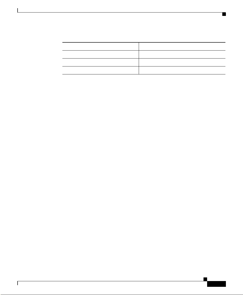
Cabling Guidelines
The GigaStack GB IC uses th e fo llowing Cisco prop rieta ry cables. See Figure 1-4
and Table 1-3 for more informa tion.
Catalyst GigaStack Gigabit Interface Converter Hardware Installation Guide
1-4
78-6460-04
Page 27

Chapter 1 Overview
Cabling Guidelines
The maximum distan ce for a GBI C-to- GBIC conn ecti on is 1 meter. The
GigaStack GBIC req uire s C isco pr opri etary si gnali ng and ca bling. Fo r more
information about ca bling , see Ap pendix B, “Connec tor s a nd Ca ble s.”
Figure 1-4 GigaStack GBIC Cables
1
3
9
1394
50-cm GigaStack cable
1394
1-m GigaStack cable
Table 1-3 GigaStack GBIC Cable Part Numbers
Part Number Cable Length
CAB-GS-50CM 50 cm
CAB-GS-1M 1 m
4
1
3
9
4
22086
78-6460-04
The 50-cm cable comes wit h the Giga Stack GBIC. You can order additional
cables.
Caution Do not use standard IEEE 1 394 cab les w ith t he G iga Stac k GBIC. You must use
one of the Cisco pr opri etar y cables (CAB-GS -50C M or CAB- GS-1M) . If you use
any other cable, you will not have conn ecti vity.
Caution Do not use the GigaStack GBIC with standard IEEE 1394 equipment. You might
damage the equipment or l ose data.
Catalyst GigaStack Gigabit Interface Converter Hardware Installation Guide
1-5
Page 28

Switches Supporting the GBIC
Switches Supporting the GBIC
Refer to the online GigaStack Gigabit Interface Converter Switch Compatibility
Matrix listed with the GBIC documen tation on w ww.cisco.com for the most
current list of product s supporti ng the GBI C.
Caution Installing the GBIC in or connecting it to an unautho rized device migh t cause
damage to the GB IC, t he oth er devi ce, or bot h.
Table 1-4 lists the switches and the module supporting the GigaStack GBIC.
Table 1-4 Switches and Module Supporting the GigaStack GBIC
Switch Series or Module Model Number Description
WS-X2931-XL m odul e for
Catalyst 2900 series XL
switches
Catalyst 2900 XL switches
Catalyst 2950 switches
WS-X2931-XL 1 1000BASE-X port
Catalyst 2912MF XL 12 100BASE-FX ports and
2 module slots
Catalyst 2924M XL 24 autosen sing 10/1 00 Ethern et
ports and 2 module slots
Catalyst 2950G-12- EI 12 auto sensing 10/ 100 Ethe rnet
ports and 2 GBIC module slots
Catalyst 2950G-24- EI 24 auto sensing 10/ 100 Ethe rnet
ports and 2 GBIC module slots
Catalyst 2950G-24- EI-DC 24 autosensing 10/100 Et hernet
ports and 2 GBIC module slots
with DC-input power
Catalyst 2950G-48- EI 48 auto sensing 10/ 100 Ethe rnet
ports and 2 GBIC module slots
Chapter 1 Overview
1
1-6
Catalyst GigaStack Gigabit Interface Converter Hardware Installation Guide
78-6460-04
Page 29

Chapter 1 Overview
Minimum IOS Release for Redundant Loop Configurations
Switch Series or Module Model Number Description
Catalyst 3500 XL switches
Catalyst 3550 switches
1. The 1000BASE-X module provides one switched 1000-Mbps port in half-duplex, full-duplex, or autonegotiation mode for a
GigaStack GBIC. The port supports the IEEE 802.3Z 1000BASE-X standard.
Catalyst 3508G X L 8 GBIC module slots
Catalyst 3512 XL 12 autosensing 10/100 Et hernet
ports and 2 GBIC module slots
Catalyst 3524 XL 24 autosensing 10/100 Et hernet
ports and 2 GBIC module slots
Catalyst 3524 PWR XL 24 autosensing 10/ 100
inline-power Ethern et ports and
2 GBIC module slots
Catalyst 3548 XL 48 autosensing 10/100 Et hernet
ports and 2 GBIC module slots
Catalyst 3550-12G 2 autosensing 10/100/ 1000
Ethernet ports and 10 GBIC
module slots
Catalyst 3550-12T 10 autosensing 10/100/10 00
Ethernet ports and 2 GBIC
module slots
Catalyst 3550-24-SMI
Catalyst 3550-24-EMI
Catalyst 3550-48-SMI
Catalyst 3550-48-EMI
24 autosensing 10/100 Et hernet
ports and 2 GBIC module slots
48 autosensing 10/100 Et hernet
ports and 2 GBIC module slots
Minimum IOS Release for Redundant Loop
Configurations
To ensure support for redundant lo op co nfigu ra tions wh en us ing th e G igaSta ck
GBIC in a cascaded sta ck co nf ig uration, make sure that every switch in the stac k
is running at least the minimum IOS Release listed in Table 1-5.
Catalyst GigaStack Gigabit Interface Converter Hardware Installation Guide
78-6460-04
1-7
Page 30

Minimum IOS Release for Redundant Loop Configurations
Table 1-5 Minimum IOS Release for Redundant Loop Configurations
Supported Switch Minimum IOS Release
Modular 2900 X L sw itch es 12.0(5)XU (April 20 00)
2950 switches 12.1(6)EA2 (Decembe r 200 0)
3500 XL switches 12.0(5)XU (April 20 00)
3550 multilayer switc hes 12.1(4)EA1 (May 200 1)
Note All switches in a series must run the same software version. For example, if the
stack includes o nly C ata lyst 2 900 serie s X L a nd 350 0 s eries XL s witc hes, th ey
must run Releas e 12.0(5 )X U o r la ter. If the st ack in clu des a m ixt ure of Cata lyst
2900 series XL, 3500 series XL, 2950, and 3550 switche s, all the 2900 XL and
3500 XL switches must run Releas e 12 .0( 5)XW or la ter, all the Ca ta lyst 2950
switches must run Release 12.1(6)EA2 or later, and all the Catalyst 3550 switches
must run Release 12.1(4 )EA1 or lat er.
Chapter 1 Overview
1-8
For more information, see the “Cascaded Stack Connections with a Redundant
Link” section on page 2-12. For s witch softwa re upg rade i nformat ion, refer t o the
release notes for your switch.
Catalyst GigaStack Gigabit Interface Converter Hardware Installation Guide
78-6460-04
Page 31

Chapter 1 Overview
Deployment Examples
This section contains examples that use the GigaStack GBIC as a Gigabit uplink
to aggregate traffic in a switched and shared network.
Example 1: Cascaded Stack Connection
Figure 1-5 shows the GigaStack GBIC cascaded in a half-duplex stack
configuration.
Figure 1-5 Cascaded Stack Connection
Catalyst 3550
switch
Gigabit EtherChannel
or 1000BASE-X link
Catalyst 2900 XL,
Catalyst 3500 XL,
or Catalyst 3550
switches
Deployment Examples
78-6460-04
10/100
switched links
10/100 attached workstations
Catalyst GigaStack Gigabit Interface Converter Hardware Installation Guide
Half-duplex
GigaStack GBIC links
48798
1-9
Page 32

Deployment Examples
Example 2: Point-to-Point Connection
Figure 1-6 shows the 3500 XL switch aggr eg ati ng t raffic b y u sing a Gig aStack
GBIC as a full -dupl ex , point- t o-poi nt u pl ink co nnec tion .
Figure 1-6 Point-to -Point Connection
Full-duplex
GigaStack GBIC
or 1000BASE-X links
Catalyst 2900 XL, Catalyst 3500 XL, or Catalyst 3550 switches
Chapter 1 Overview
Catalyst 3508G XL switch
48799
1-10
Catalyst GigaStack Gigabit Interface Converter Hardware Installation Guide
78-6460-04
Page 33

Installation
This chapter d escrib es how to unpa ck , instal l, c able, a nd ru n t he pow er-on
self-test (POST) on the GigaStack GBIC. After power on, you can manage GBIC
ports as you would manage fixed port s on the switch , through the web-based
Cluster Management Suit e (CMS), or th rough the console por t or a Telnet
connection to access the IOS command-line interface.
Inspecting the Packing List
Before you install a GigaStack GBIC, ensure that these items are included in the
package:
• GigaStack GBIC
• 50-cm cable
CHAPTER
2
78-6460-04
• GBIC clip
If anything is missing, cont act your Cisc o Systems custo mer servi ce
representative.
Note You ca n orde r a 1- m cabl e se para te ly.
Catalyst GigaStack Gigabit Interface Converter Hardware Installation Guide
2-1
Page 34

EMC Regulatory Statements
EMC Regulatory Statements
This section lists international regulatory information for the GigaStack GBIC.
U.S.A.
U.S. regulatory information for this product is in the front matter of this manual.
Taiwan
This is a Class A Information product. When used in a residential environment, it
may cause radio frequency interference. Under such circumstances, the user may
be requested to take appropriate countermeasures.
Chapter2 Installation
Japan
2-2
This is a Class A product based on the standard of the Voluntary Control Council
for Interference by Information T echnology Equipment (VCCI). If this equipment
is used in a domestic envir onment , radio dist urbance may arise. Wh en such
trouble occurs, the use r may be requir ed to tak e correc tive ac tions.
46464
Catalyst GigaStack Gigabit Interface Converter Hardware Installation Guide
78-6460-04
Page 35

Chapter 2 Installation
Korea
EMC Regulatory Statements
Hungary
Warning
This is a Class A Device and is registered for EMC requirements for
industrial use. The seller or buyer should be aware of this. If this type was
sold or purchased by mistake, it should be replaced with a residential-use
type.
This equipment is a Cl ass A p rod uct and shou ld b e use d and insta ll ed pr operl y
according to the Hungarian EMC Class A requirements (MSZEN55022). Class A
equipment is designed for typical commercial establishments for which special
conditions of install ation and pro tectio n distan ce are use d.
Figyelmeztetés a felhasználói kézikönyv számára:
Ez a berendez és “A” osztályú termék, felhasználására és üzembe he lyezésére a
magyar EMC “A” osztályú követe lményeknek (MSZ EN 5 502 2) meg
feleloen
kerülhet sor, illetve ezen “A” osztályú berendezések csak megf elelo kere skedelmi
forrásból származhat nak , amelye k bizto sítják a megfel elo speci ális üzembe
helyezési körülményeket és biztonságos üzemelési távolságok alk almaz ását.
78-6460-04
Catalyst GigaStack Gigabit Interface Converter Hardware Installation Guide
2-3
Page 36

Avoiding Electros tatic Discharge
Avoiding Electrostatic Discharge
Before you install the Giga Stac k GBIC , g ro und yourse lf by touc hing the me tal
part of the cha ssis t o avoi d ele ctrost atic disc harge ( ESD). You should also keep
the GigaStack GBIC in its antistatic shielded bag until you are ready for
installation.
Installing a GigaStack GBIC
Gigabit Ethernet switches are shipped without the GigaStack GBIC. However,
you can install the GBI C into Gi gaStac k GBIC slot s, as sh ow n in Figur e 2-1.
Install a GigaStack GBIC as follows:
Step 1 Remove the GigaStack GBIC fr om its prote ctive packa ging.
Step 2 If you want to use the G igaSta ck cabl e conn ector (h erea fter re ferr ed to as the
clip), see the “Attaching the GBIC Clip” section on page 2-6.
Chapter2 Installation
2-4
Step 3 Grip the sides of the G BI C with your thum b a nd fore fin ge r, and insert it int o the
GBIC slot on a switch front panel, as shown in Figu re 2-1, or the
Catalyst 2900 XL 1 000B ASE-X mod ule slot , a s sh own in Figu re 2-2.
The GigaStack GBIC is keyed to prevent incorrect insertion.
Step 4 Slide the GigaStack GBIC through the flap covering the opening into the slot until
you hear a click. The click means the GigaStack GBIC is locked into the slot.
Catalyst GigaStack Gigabit Interface Converter Hardware Installation Guide
78-6460-04
Page 37

Chapter 2 Installation
Installing a GigaStack GBIC
Figure 2-1 Inserting the GigaStack GBIC into a Switch Module Slot
Metal flap door
S
Y
S
T
E
M
R
P
S
S
T
A
T
U
M
O
D
S
E
U
T
IL
D
U
P
L
X
S
P
E
E
D
1
2
3
GBIC module slot
1
2
GigaStack GBIC
Figure 2-2 Inserting the GigaStack GBIC into a 1000BASE-X Module
Metal flap door
GBIC LED
Tighten
Screws
To Activate
WS-X2931-XL
10
0
0
B
a
se
X
Slot for
1
2
GigaStack GBIC
22081
22085
78-6460-04
GigaStack GBIC
Catalyst GigaStack Gigabit Interface Converter Hardware Installation Guide
2-5
Page 38

Attaching the GBIC Clip
Attaching the GBIC Clip
Each GigaStack GBI C ships with a remo vable clip that can b e attach ed to prov ide
extra security agains t acc ident al cabl e remova l. If yo u use the clip, you must
attach it before inserting the GBIC into the slot.
Attach the clip as follows:
Step 1 Attach the clip to the GBIC by carefully inserting the clip tabs into the slots on
either side of the GBIC, in the orientation shown in Figure 2-3. Slide the clip
toward the port side of the G BIC.
Figure 2-3 Attaching the GBIC Clip
Chapter2 Installation
Tab
2-6
1
GigaStack GBIC ports
Step 2
Step 3 Swing the GBIC clip up toward the GBIC so that the alignment bump in the clip
Insert the cable connector into the GBIC port according to your configuration.
2
Alignment bump
Notches on clip
32256
seats in the indentation on the GBIC bottom.
Catalyst GigaStack Gigabit Interface Converter Hardware Installation Guide
78-6460-04
Page 39

Chapter 2 Installation
Step 4 Secure the cable in a clip notch as shown in Figure 2-4.
Recommended Configuration
Figure 2-4 Securing the Cables in the GBIC Clip
6
7
8
1
2
32257
Clip installed on GBIC
Step 5
Insert the GBIC into the slot. Follow the steps in the “Installing a GigaStack
GBIC” section on page 2-4.
Recommended Configuration
All ports are set to autonegotiate the duplex mode for your GigaStack GBIC. You
must keep this default setting; autonegotiation must not be disabled.
For information about the supporting switches and software, see the “Switches
Supporting the GBIC” section on page 1-6 and the “Minimum IOS Release for
Redundant Loop Confi g urat ions” section on pa ge 1-7.
Connecting to GigaStack GBIC Ports
78-6460-04
Insert the GigaStack cable connector into the GigaStack GBIC port, as shown in
Figure 2-5.
Note The GBIC module slot LED is amber while the Spanning Tree Protocol discovers
the topology and searches for loops. This takes about 30 seconds. The port status
LED then turns green.
Catalyst GigaStack Gigabit Interface Converter Hardware Installation Guide
2-7
Page 40

Creating Connections
Figure 2-5 Inserting the Cable in a GigaStack GBIC
Chapter2 Installation
22082
1
S
Y
S
T
E
M
R
P
S
S
T
A
T
U
S
M
O
D
E
U
T
I
L
D
U
P
L
X
S
P
E
E
D
1
1
3
9
4
2
2
1
2
3
GBIC module slots
GigaStack cable
1
3
9
4
Note Always use a Giga Stack ca ble to c onnec t a Gi gaSt ack G BIC t o any d ev ice . For
more information, see the “GigaStack GBIC Cabling” section on page B-1.
Creating Connections
You ca n c rea t e t hes e confi g urat ions:
• Point-to-point
• Cascaded stack
4
5
6
7
8
2-8
• Cascaded stack with a redunda nt link
In a point-to-poi nt co nfigu ra tion o r ca scad ed stac k conf igura ti on, t he G iga Sta ck
GBIC can use the ports listed in Table 2-1 to connect to ot her dev ices.
Catalyst GigaStack Gigabit Interface Converter Hardware Installation Guide
78-6460-04
Page 41

Chapter 2 Installation
Note The GigaStack GBIC support s setting a trun k to IEEE 802 .1Q or Inter-Swit ch
Creating Connections
Table 2-1 Available GBIC Ports in a Point-to-Point Configuration
Available GigaStac k
Device
1000BASE-X module ( for m odu lar
2900 XL switches)
3500 XL switches 2
2950 switches 2
3550 multilayer switches 2
Link (ISL) encapsulation. All GigaStack GBIC interfaces in the cascaded stack
should be configured as trunk inter faces (switchport mode trunk interface
configuration com ma nd) a nd to use the sam e en ca psula tion m eth od ( switchport
trunk encapsulation {isl | dot1q} interface configuration command). For more
information on these commands, refer to the command reference for your switch.
GBIC Ports
2
78-6460-04
For more informat ion, see the “Point-to-Point Connections” section on page 2-10,
the “Cascaded Stack Conn ections” section on page 2-1 1, and the “Cascaded Stack
Connections with a Redundant Link” section on page 2-12.
Catalyst GigaStack Gigabit Interface Converter Hardware Installation Guide
2-9
Page 42

Creating Connections
Point-to-Point Connections
A point-to-point co nne ction o pe rate s in f ull -du plex m ode. Fi gure 2-6 shows an
example of suppo rti ng sw itche s w ith poi nt- to-p oint con ne ctions.
Figure 2-6 Point-to -Point Connections
Chapter2 Installation
1
2 3 4 5 6 7 8 9 10 11 12 13 14 15 16 17 18 19 20 21 22 23 24
1X
M
T
E
S
Y
S
S
P
R
T
S
A
T
U
S
E
M
D
O
L
T
I
U
2X
L
U
P
X
D
D
E
E
P
S
11X
12X
Catalyst 3500
1
XL
2
2
1
Catalyst 2900
2
1
1
x
2
x
3
x
4
x
5
x
6
x
7
x
8
x
9
x
1
0
x
1
1
x
1
2
M
O
D
E
x
1
7
x
1
8
x
1
9
x
2
0
1
3
x
1
4
x
1
5
x
1
6
x
2
1
x
2
2
x
2
3
x
2
x
4
x
2 3 4 5 6 7 8 9 10 11 121
1X
M
T
E
S
Y
S
S
P
R
T
A
S
S
T
U
M
D
O
E
L
T
I
U
2X
X
L
P
D
U
D
E
E
P
S
1
M
T
E
S
Y
S
S
R
P
T
S
A
S
T
U
M
O
E
D
L
T
I
U
X
L
P
D
U
D
E
E
P
S
11X
13X
12X
14X
3
2
4
15X
16X
5
Catalyst 3500
1
6
Catalyst 3500
7
2
1
8
1
Catalyst 3508G XL
Catalyst 2924M XL
Catalyst 3512 XL Catalyst 3524 XL
Catalyst 3524 XLCatalyst 3512 XL
1
2 3 4 5 6 7 8 9 10 11 12 13 14 15 16 17 18 19 20 21 22 23 24
1X
M
T
E
S
Y
S
S
R
P
T
S
A
T
U
S
M
D
O
E
U
L
T
I
2X
D
L
U
P
X
D
E
E
P
S
11X
12X
Catalyst 3500
1
XL
2
2
1
Catalyst 2900
2
1
1
x
2
x
3
x
4
x
5
x
6
x
7
x
8
x
9
x
1
0
x
1
1
x
1
2
x
1
3
x
1
4
x
1
5
x
1
6
x
1
7
x
1
8
x
1
9
x
2
0
x
2
1
x
2
2
x
2
3
x
2
4
M
O
D
E
x
2 3 4 5 6 7 8 9 10 11 121
1X
M
T
E
S
Y
S
S
R
P
D
O
E
M
T
S
A
T
U
S
U
L
T
I
2X
D
L
U
P
X
D
E
E
P
S
1
M
T
E
S
Y
S
S
R
P
T
S
A
T
U
S
M
D
O
E
U
L
T
I
D
L
U
P
X
D
E
E
P
S
11X
13X
12X
14X
3
2
4
15X
16X
5
Catalyst 3500
1
6
Catalyst 3500
7
2
1
8
1
Catalyst 3508G XL
Catalyst 2924M XL
XL
2
XL
22304
2
XL
2
XL
22305
2
2-10
Catalyst GigaStack Gigabit Interface Converter Hardware Installation Guide
78-6460-04
Page 43

Chapter 2 Installation
Cascaded St ack C onn ec tio ns
You can con nect from t hree to nine switches in a ca scad ed stack conf igurat ion.
The cascad ed sta ck o per a tes in ha l f- dup lex mo de . Figure 2-7 shows the
connections on some supporting switches.
Figure 2-7 Cascaded Stack Connections
Catalyst 3508G XL
3
2
1
T
S
Y
M
S
E
R
S
P
T
S
A
S
T
U
M
E
O
D
T
L
I
U
U
X
L
P
D
D
E
E
P
S
Creating Connections
Port 1
Port 2
Catalyst 3500
5
4
7
6
XL
8
2
1
Catalyst 2924M XL
1x
2x
3x
4x
M
O
D
E
5x 6x
Catalyst 3512 XL
1
2 3 4 5 6 7 8 9 10 11 12
1X
T
S
Y
M
S
E
R
S
P
T
S
A
T
U
S
O
D
M
E
U
T
L
I
2X
D
U
L
P
X
D
E
E
P
S
Catalyst 3524 XL
1
2 3 4 5 6 7 8 9 10 11 12
1X
T
S
Y
M
S
E
R
S
P
T
S
A
T
U
S
O
D
M
E
U
T
L
I
2X
U
X
L
P
D
D
E
E
P
S
7x
8x
11X
12X
11X
12X
9x
10x
11x
12x
13x 14x
13 14 15 16 17 18 1920 21 22 23 24
13X
14X
Catalyst 2900
2
1
17x
18x
19x
20x
15x
16x
15X
16X
21x 22x
23x
24x
Catalyst 3500
Catalyst 3500
XL
2
2
1
XL
2
2
1
22124
1
1
78-6460-04
Catalyst GigaStack Gigabit Interface Converter Hardware Installation Guide
2-11
Page 44

Creating Connections
Cascaded Stac k Co nn ectio ns with a R edun dan t Lin k
Y ou can form a redundant link by connecting the open ports on the top and bottom
GigaStack GBICs within the same stack, as shown in Figure 2-8.
Figure 2-8 Cascaded Stack Connections with a Redundant Link
Port 1
Catalyst 3508G XL
1
T
S
Y
M
S
E
R
S
P
T
S
A
S
T
U
M
E
O
D
U
T
L
I
X
L
P
D
U
D
E
E
P
S
5
3
2
4
6
Catalyst 3500
7
1
Port 2
XL
8
2
Chapter2 Installation
Catalyst 3512 XL
9
56 78
10
2
1
1
1
11X
12X
Catalyst 3500
1
XL
2
2
1
Redundant
34
12
1X
T
S
Y
M
S
E
R
S
P
T
S
A
T
U
S
M
O
D
E
U
T
L
I
2X
D
U
L
P
X
D
E
E
P
S
link
Catalyst 3524 XL
9
0
56 78
1
2
1
1
1
34
12
1X
T
S
Y
M
S
E
R
S
P
T
S
A
T
U
S
M
O
D
E
U
T
L
I
2X
D
U
L
P
X
D
E
E
P
S
15 16
13 14
13X
14X
17 18 19 20 21 22 23 24
15X
16X
11X
12X
Catalyst 3500
1
XL
2
2
1
31116
The GigaStack GBIC softw are detect s the loop conf igurati on by the way th e
cables are connected and the number of switches used in the stack. The software
uses one of the GigaStack GBIC links as the redundant link, which is disabled for
data transmission while all the other links in the stack are up. When any other link
in the stack is do wn , t he redu nda nt lin k is au to mat ica lly ena ble d f or dat a
transmission. To ensure continued connectivity, the software periodically checks
for changes in the stack and invokes the loop detection algorithm if a new link is
added to the cascaded st ack or if a lin k is remove d from the c ascade d stack.
GigaStack GBICs installed in a stack support a loop configuration only if every
Catalyst 2900 XL and 3500 XL switch in the stack is running IOS software
Release 12.0(5)XU or lat er, Release 12.1(6) EA2 or later for Catalyst 2950
switches, and Release 12.1( 4)EA 1 or later for Cat alyst 3550 switches.
For Catalyst 2900 XL and 3500 XL switches running IOS soft ware earlie r than
Release 12.0(5)XU, an illegal loop is crea ted unde r thes e conditi ons:
• A GigaStack GBIC is connected to two other GBIC ports in the same stack.
2-12
• A single GigaStack GBIC cable is inserted in port 1 and port 2 of the same
GBIC.
Catalyst GigaStack Gigabit Interface Converter Hardware Installation Guide
78-6460-04
Page 45

Chapter 2 Installation
Caution A loop causes excessive collision errors on the port and can cause the link to
Removing a GigaStack GBIC
become unstable. This instability decreases performance on the links, and
communication between the switches in the stack is adversely affected.
If a Catalyst switch is connected th rough its G iga Stac k GBIC to an othe r switch ’s
GigaStack GBIC th at do es n ot su p port loop detection, the GBIC LEDs turn t he s e
colors:
• The GigaStack GBIC LED on the switch without loop detection turns green
almost immediately.
• The GigaStack GBIC L ED on the s witch with loop detection flashes green for
15 seconds and then turns gre en.
As a result, all GBIC links are enabled if no loop is created. If a loop is
present, the software does not detect it, excessive collisions occur on these
ports, no traffic passes through the st ack, and the GigaStac k GBIC LED s
remain green.
To avoid problems with loop configurations, make sure that all switches in your
stack are running the appropriate IOS release as shown in Table 1-5 on page 1-8.
For more information, see the “Minimum IOS Release fo r Redundan t Loop
Configurations” se cti on on p age 1-7. For switch sof tware upgr ade i nformat ion,
refer to the re lea se note s for y our swi tch .
Removing a GigaStack GBIC
Remove a GigaStack GBIC as follows:
Step 1 Release the GigaStack GBIC fr om the slot by si multane ously squeez ing the two
plastic tabs (one on e ach side of t he Giga Sta ck G BIC ).
Step 2 To remove, slide the GigaStack GBIC out of the slot. A flap drops down to protect
the internal connector.
Catalyst GigaStack Gigabit Interface Converter Hardware Installation Guide
78-6460-04
2-13
Page 46

Power-On Self-Test
Step 3 If you are using the GBIC clip to secure the GBIC cables, remove the clip from
Step 4 Disconnect the cable from the GigaStack GBIC port.
Chapter2 Installation
the GigaStack GBIC by pulling the tabs from the slots on the GBIC. Remove the
cables from the notches in the clip.
Warning
Ultimate disposal of this product should be handled according to all national
laws and regulations.
Power-On Self-Test
All supporting switches perform a power-on self-te st (POST) on the G igaStac k
GBIC. When you insert the GigaStack GBIC into the switch or module slot, the
port LED on the switch or module tu rns amber w hile STP chec ks for possibl e
loops and then tu rns gree n. Wh en yo u inser t a Gi gaSt ack GBIC c able in to th e
GBIC port, the GigaStack GBIC port turns green if there is network connectivit y;
no additional configurat ion is neede d. For mor e inform ation a bout the LED
meanings, see the “GigaStack GBIC LEDs” section on page 1-2 and the “GBIC
Module Slot LEDs” section on page 1-3.
2-14
Catalyst GigaStack Gigabit Interface Converter Hardware Installation Guide
78-6460-04
Page 47

CHAPTER
Troubleshooting
Table 3-1 describes how to identify problems with the switch and GigaStack
GBIC and how to resolve them.
Table 3-1 Common Problems and Their Solutions
Symptom Possible Causes Corrective Action
GBIC module slot
LED is amber.
GBIC module slot
LED is flashing
green and amber.
GBIC module slot
LED is off.
Spanning Tree Protocol
(STP) is chec king f or loops .
Port is initializing, it was
disabled by manageme nt or
an address violation, or it
was blocked by STP.
Port is experie ncing er ror
frames. This coul d be du e to
a duplex mismatch cause d
by autonegotia tion,
collisions, cyclic
redundancy c heck ( CRC)
errors, or alignment errors.
Device has no power. Ensure that the switch and the target device have
No link or port wa s shut
down administratively.
Bad cable. Replace with a k now n goo d ca ble .
Wait for STP to complete its search. The LED
turns green when S T P c om pl ete s i ts ch ec k.
Use the Cluster Management Suite or the IOS
command-line interface to check the status of the
port and to enable it.
Remove and reinsert the Gi gaStack GB IC.
power.
V erify that the GBIC cable is connected to another
active network device and that the port is not shut
down.
3
78-6460-04
Catalyst GigaStack Gigabit Interface Converter Hardware Installation Guide
3-1
Page 48

Table 3-1 Common Problems and Their Solutions (continued)
Symptom Possible Causes Corrective Action
GigaStack GBIC
LED blinks any
color for more tha n
1 minute.
GigaStack GBIC
LED color is
incorrect (for
example, the GBIC
is not connected to
another device, but
the LED is green).
Link flap (the link keeps
going up and do wn ).
The GigaStack GBIC i s in
an indeterminate state.
Remove and reinsert the GigaStack GB IC.
Upgrade all the switches in a series to the same
software version; o ther wise, t he l oo p-bre a king
algorithm might never resolve itself. For example,
if the stack includes only Catalyst 2900 series XL
and 3500 series XL switches, they must run
Release 12.0(5)XU or later. If the stack includes a
mixture of Catalyst 2900 series XL,
3500 series XL, 295 0, and 355 0 switches, all the
2900 XL and 3500 XL switches must run
Release 12.0(5)XW or later, all Catalyst 2950
switches must run Relea se 12 .1( 6)EA2 or late r,
and all Catalyst 35 50 switches must run
Release 12.1(4)EA1 or later.
If no loop exists in the Gi gaStack GBIC stack, you
can disable the loop-br eakin g algorit hm by using
the no gigastack loop-breaking [interface-id]
global configuration c omma nd.
Remove and reinsert the GigaStack GB IC.
Chapter3 Troubleshooting
3-2
Catalyst GigaStack Gigabit Interface Converter Hardware Installation Guide
78-6460-04
Page 49

APPENDIX
A
Technical Specifications
Table A-1 lists the technical specifications an d regulatory agency approvals for
the GigaStack GBIC.
Table A-1 Technical Specifications
Environmental Ranges
Operating temperature 32 to 113
Storage temperature –4 to 149
Operating humidi ty 10 to 85% (nonco ndensi ng)
Storage humidity 5 to 95% (noncondensing)
Operating alti tud e Up to 10,000 ft (3 000 m)
Storage altitude Up to 15,000 ft (4 570 m )
Power Consumpt ion 2W
Physical Dimensions (H x W x D) 0.75 x 1.54 x 3. 5 in. (1.90 x 3.91 x 8.8 9 cm)
We ight 0.11 lb (0.05 kg)
°F (0 to 45°C)
°F (–20 to 65°C)
78-6460-04
Catalyst GigaStack Gigabit Interface Converter Hardware Installation Guide
A-1
Page 50

Appendix A Technical Specifications
Table A-1 Technical Specifications (continued)
Agency Appro v al s
Safety EMI
AS/NZS 3260, TS001 FCC Part 15 Cla ss A
UL 1950/CSA 22.2 N o. 95 0 EN 55022A Cla ss A (CI SPR 22 Class A )
IEC 950/EN 60950 VCCI Class A
CE AS/NRZ 3548 Class A
BCIQ
CE
A-2
Catalyst GigaStack Gigabit Interface Converter Hardware Installation Guide
78-6460-04
Page 51

Connectors and Cables
This appendix describes the Ci sco propri etary cabl es and connec tors for the
GigaStack GBIC.
GigaStack GBIC Cabling
The GigaStack GBIC uses pr oprieta ry connec tors as show n in Figure B-1.
Figure B-1 GigaStack GBIC Connector
22084
APPENDIX
B
78-6460-04
The GigaStack GBIC ca b les a re p rop rie tar y, high-data-rate cab le s wit h en ha nced
signal integrity a nd EMI pe rform a nce.
Caution Do not use standard IEEE 1 394 cab les w ith t he G iga Stac k GBIC. You must use
one of the Cisco pr opri etar y cables (CAB-GS -50C M or CAB- GS-1M) . If you use
any other cable, you will not have conn ecti vity.
Caution Do not use the GigaStack GBIC with standard IEEE 1394 equipment. You might
damage the equipment or l ose data.
Catalyst GigaStack Gigabit Interface Converter Hardware Installation Guide
B-1
Page 52

GigaStack GBIC Cabling
Appendix B Connectors and Cables
B-2
Catalyst GigaStack Gigabit Interface Converter Hardware Installation Guide
78-6460-04
Page 53

Translated Safety Warnings
This appendix repeats the warnings in this guide in multiple languages.
Product Disposal
Warning
Waarschuwing
Ultimate disposal of this product should be handled according to all national
laws and regulations.
Het uiteindelijke wegruimen van dit product dient te geschieden
in overeenstemming met alle nationale wetten en reglementen.
APPENDIX
C
Avvertenza
78-6460-04
Varoitus
Attention
Warnung
Tämä tuote on hävitettävä kansallisten lakien ja määräysten
mukaisesti.
La mise au rebut ou le recyclage de ce produit sont généralement
soumis à des lois et/ou directives de respect de l'environnement.
Renseignez-vous auprès de l'organisme compétent.
Die Entsorgung dieses Produkts sollte gemäß allen
Bestimmungen und Gesetzen des Landes erfolgen.
Lo smaltimento di questo prodotto deve essere eseguito secondo
le leggi e regolazioni locali.
Catalyst GigaStack Gigabit Interface Converter Hardware Installation Guide
C-1
Page 54

Product Disposal
Appendix C Translated Safety Warning s
Advarsel
Aviso
¡Advertencia!
Varning!
Endelig kassering av dette produktet skal være i henhold til alle
relevante nasjonale lover og bestemmelser.
Deitar fora este produto em conformidade com todas as leis e
regulamentos nacionais.
Al deshacerse por completo de este producto debe seguir todas
las leyes y reglamentos nacionales.
Vid deponering hanteras produkten enligt gällande lagar och
bestämmelser.
C-2
Catalyst GigaStack Gigabit Interface Converter Hardware Installation Guide
78-6460-04
Page 55

INDEX
Numerics
1000BASE-X module
description
IEEE standards 1-7
1-7
A
agency approva l s A-2
alignment errors 1-4
autonegotiation 2-7
C
cable
1-m cable availability
description and cauti ons B- 1
guidelines 1-5, B-1
lengths 1-5
part numbers 1-5, B-1
proprietary requir ements 1-5
standard IEEE 1 394 c able ca uti on 1-5, B-1
Cisco IOS command-line inter face, (CLI ) 1-2
Cisco Techni ca l A ss is ta nce C en ter xxi
clip, attaching 2-6to2-7
2-1
Cluster Management Suite (CM S) 1-2
collision errors 2-13
CRC errors 1-4
D
definitions, notes, ca utions , warnings xiv
deployment examp les 1-9 to1-10
disabled port 1-4
distance limitations 1-5
documentation
feedback
obtaining
CD-ROM
world wide web xviii
ordering xix
related xvii
duplex mode, re co mm en ded 2-7
xix
xix
E
electrostatic discharge (ESD) 2-4
EMC regulatory statem ents 2-2
EMI agency approvals A-2
78-6460-04
Catalyst GigaStack Gigabit Interface Converter Hardware Installation Guide
IN-1
Page 56

Index
error frames
detecting
3-1
LED indication 1-4
Spanning Tree Protoco l 3-1
F
features 1-1 to 1-2
feedback to Ci sc o Sy s tem s, we b xix
G
GigaStack cable connector, see clip
GigaStack GBIC
cabling guidelines
connecting port s 2-7
definition xiii
deployment examples
cascaded c onn ect io n
point-to-point connection 1-10
installing 2-4
keyed insertion p rotec tio n 2-4
LED descriptions 1-3
minimum IOS Release 1-7
part number 1-1
recommended d uple x mod e 2-7
redundant loop supp ort 1-7, 2-12
removing 2-13
specifications A-1 to A-2
1-5
1-9
supported switches 1-6
GigaStack Gigabit Interface Converter,
see GigaStack GBIC
I
IEEE 1394 (sta nd ar d) c ab le caut ion 1-5
IEEE standards
802.1Q
2-9
802.3Z 1-7
installation procedure 2-4 to 2-7
Inter-Switch Link ( ISL ) mode , sup por t 2-9
IOS software
illegal loops with
2-12
support 1-2, 1-7
IP address, managing a stack 1-1
L
LEDs
color meanings
during Spanning Tre e Pro toco l 2-7
POST failure 1-3
troubleshooting 3-1to 3-2
link, point-to-point 1-1
link flap 3-2
loop detection 2-12
1-2 to 1-4
IN-2
Catalyst GigaStack Gigabit Interface Converter Hardware Installation Guide
78-6460-04
Page 57

Index
N
network examples 1-9
note definition xiv
P
packing list 2-1
POST
conditional limitations
2-14
LED indicator 1-3
power-on self-test, se e POST
product disposal
C-1
R
redundant links
configuration ex ample
2-12
supported IOS Release 1-7, 2-12
regulatory statem en ts 2-2
related publications xvii
removing a GigaStack GBIC 2-13
S
safety
agency approva l s
warnings, translated C-1
A-2
Spanning Tree Protoc ol
LED state duri ng
2-7
port blocking 1-4
specifications A-1
stacking
full-duplex ca scad ed examp le
half-duplex cascad ed exa mple 1-9
redundant link e xamp le 2-12
switches, supported
IOS release requ ireme nts
1-7
support for GigaStack GBIC 1-6
T
TAC
described
toll-free telephon e numbe rs xxi i
technical assistance
Cisco.com
TAC website xxi
technical specifications A-1
topology
cascaded
point-to-point 1-10
redundant link 2-12
troubleshooting 3-1to 3-2
trunking 2-9
xxi
xx
1-9
1-10
78-6460-04
Catalyst GigaStack Gigabit Interface Converter Hardware Installation Guide
IN-3
Page 58

Index
U
URLs, Cisco xviii
W
warnings, Product Disp osal C-1
World Wide Web, do cu me nta tion f ro m xvi ii
IN-4
Catalyst GigaStack Gigabit Interface Converter Hardware Installation Guide
78-6460-04
 Loading...