

Page 1

Cisco 170 Series Hardware Installation Guide
For Cisco C170 Email Security Appliance, Cisco M170 Content Security
Management Appliance, and Cisco S170 Web Security Appliance
Americas Headquarters
Cisco Systems, Inc.
170 West Tasman Drive
San Jose, CA 95134-1706
USA
http://www.cisco.com
Tel: 408 526-4000
800 553-NETS (6387)
Fax: 408 527-0883
Text Part Number: OL-28365-01
Page 2

THE SPECIFICATIONS AND INFORMATION REGARDING THE PRODUCTS IN THIS MANUAL ARE SUBJECT TO CHANGE WITHOUT NOTICE. ALL
STATEMENTS, INFORMATION, AND RECOMMENDATIONS IN THIS MANUAL ARE BELIEVED TO BE ACCURATE BUT ARE PRESENTED WITHOUT
WARRANTY OF ANY KIND, EXPRESS OR IMPLIED. USERS MUST TAKE FULL RESPONSIBILITY FOR THEIR APPLICATION OF ANY PRODUCTS.
THE SOFTWARE LICENSE AND LIMITED WARRANTY FOR THE ACCOMPANYING PRODUCT ARE SET FORTH IN THE INFORMATION PACKET THAT
SHIPPED WITH THE PRODUCT AND ARE INCORPORATED HEREIN BY THIS REFERENCE. IF YOU ARE UNABLE TO LOCATE THE SOFTWARE LICENSE
OR LIMITED WARRANTY, CONTACT YOUR CISCO REPRESENTATIVE FOR A COPY.
The following information is for FCC compliance of Class A devices: This equipment has been tested and found to comply with the limits for a Class A digital device, pursuant
to part 15 of the FCC rules. These limits are designed to provide reasonable protection against harmful interference when the equipment is operated in a commercial
environment. This equipment generates, uses, and can radiate radio-frequency energy and, if not installed and used in accordance with the instruction manual, may cause
harmful interference to radio communications. Operation of this equipment in a residential area is likely to cause harmful interference, in which case users will be required
to correct the interference at their own expense.
The following information is for FCC compliance of Class B devices: This equipment has been tested and found to comply with the limits for a Class B digital device, pursuant
to part 15 of the FCC rules. These limits are designed to provide reasonable protection against harmful interference in a residential installation. This equipment generates,
uses and can radiate radio frequency energy and, if not installed and used in accordance with the instructions, may cause harmful interference to radio communications.
However, there is no guarantee that interference will not occur in a particular installation. If the equipment causes interference to radio or television reception, which can be
determined by turning the equipment off and on, users are encouraged to try to correct the interference by using one or more of the following measures:
• Reorient or relocate the receiving antenna.
• Increase the separation between the equipment and receiver.
• Connect the equipment into an outlet on a circuit different from that to which the receiver is connected.
• Consult the dealer or an experienced radio/TV technician for help.
Modifications to this product not authorized by Cisco could void the FCC approval and negate your authority to operate the product.
The Cisco implementation of TCP header compression is an adaptation of a program developed by the University of California, Berkeley (UCB) as part of UCB’s public
domain version of the UNIX operating system. All rights reserved. Copyright © 1981, Regents of the University of California.
NOTWITHSTANDING ANY OTHER WARRANTY HEREIN, ALL DOCUMENT FILES AND SOFTWARE OF THESE SUPPLIERS ARE PROVIDED “AS IS” WITH
ALL FAULTS. CISCO AND THE ABOVE-NAMED SUPPLIERS DISCLAIM ALL WARRANTIES, EXPRESSED OR
LIMITATION, THOSE OF MERCHANTABILITY, FITNESS FOR A PARTICULAR PURPOSE AND NONINFRINGEMENT OR ARISING FROM A COURSE OF
DEALING, USAGE, OR TRADE PRACTICE.
IN NO EVENT SHALL CISCO OR ITS SUPPLIERS BE LIABLE FOR ANY INDIRECT, SPECIAL, CONSEQUENTIAL, OR INCIDENTAL DAMAGES, INCLUDING,
WITHOUT LIMITATION, LOST PROFITS OR LOSS OR DAMAGE TO DATA ARISING OUT OF THE USE OR INABILITY TO USE THIS MANUAL, EVEN IF CISCO
OR ITS SUPPLIERS HAVE BEEN ADVISED OF THE POSSIBILITY OF SUCH DAMAGES.
Cisco and the Cisco logo are trademarks or registered trademarks of Cisco and/or its affiliates in the U.S. and other countries. To view a list of Cisco trademarks, go to this
URL:
www.cisco.com/go/trademarks. Third-party trademarks mentioned are the property of their respective owners. The use of the word partner does not imply a partnership
relationship between Cisco and any other company. (1110R)
Any Internet Protocol (IP) addresses and phone numbers used in this document are not intended to be actual addresses and phone numbers. Any examples, command display
output, network topology diagrams, and other figures included in the document are shown for illustrative purposes only. Any use of actual IP addresses or phone numbers in
illustrative content is unintentional and coincidental.
Cisco 170 Series Hardware Installation Guide
© 2012 Cisco Systems, Inc. All rights reserved.
IMPLIED, INCLUDING, WITHOUT
Page 3

CONTENTS
Preface vii
Contents vii
Document Objectives vii
Audience vii
Document Organization viii
Document Conventions viii
Installation Warnings ix
Where to Find Safety and Warning Information xiii
Related Documentation xiii
Obtaining Documentation and Submitting a Service Request xiii
CHAPTER
CHAPTER
1 Cisco 170 Series Appliance 1-1
Cisco 170 Series Overview 1-1
Cisco C170 Email Security Appliance 1-2
Cisco M170 Content Security Management Appliance 1-2
Cisco S170 Web Security Appliance 1-2
Cisco 170 Series Appliance Panels 1-3
Front Panel LEDs 1-3
Rear Panel LEDs 1-5
Rear Panel Ports 1-6
Alarm LED 1-8
Management Interface 1-8
Hard Disk Drives 1-8
Hardware and Technical Specifications 1-9
2 Preparing for Installation 2-1
Installation Overview 2-1
Safety Recommendations 2-2
Maintaining Safety with Electricity 2-2
Preventing Electrostatic Discharge Damage 2-3
Working in an ESD Environment 2-3
OL-28365-01
General Site Requirements 2-4
Site Environment 2-4
Cisco 170 Series Hardware Installation Guide
iii
Page 4

Contents
Preventive Site Configuration 2-4
Power Supply Considerations 2-5
Configuring Equipment Racks 2-7
CHAPTER
CHAPTER
3 Installing and Connecting the Cisco 170 Series Appliance 3--1
Installing the Cisco 170 Series Appliance with Slide Rails 3--1
Verifying the Box Contents 3--1
Disassembling the Slide Rail 3-0
Attaching Inner Rails to the Appliance 3-1
Verifying the Rack Type 3-2
Securing Round Hole Racks 3-3
Securing Threaded Hole Racks 3-3
Attaching the Outer Slide Rail to Round and Square Hole Racks 3-4
Attaching the Outer Slide Rail to Threaded Hole Racks 3-5
Installing the Appliance 3-6
Securing the Appliance 3-7
Rack Mounting the Cisco 170 Series Appliance 3-8
Guidelines and Recommendations 3-8
Rack Mounting the Cisco C170, Cisco M170, or Cisco S170 Appliances 3-8
Connecting the Interface Cables and Verifying Connectivity 3-10
4 Maintaining the Cisco 170 Series Appliance 4-1
APPENDIX
iv
Fixed AC Power Supply 4-1
Removing and Installing Hard Disk Drives 4-1
Maintenance Scenarios 4-2
Replacing the Hard Disk Drives 4-2
Contacting Service and Support 4-3
A Identifying Cable Pinouts A-1
10/100/1000BaseT Connectors A-1
Console Port (RJ-45) A-2
RJ-45 to DB-9 A-3
Cisco 170 Series Hardware Installation Guide
OL-28365-01
Page 5

Preface
Contents
This preface includes the following sections:
• Document Objectives, page vii
• Audience, page vii
• Document Organization, page viii
• Document Conventions, page viii
• Installation Warnings, page ix
• Where to Find Safety and Warning Information, page xiii
• Related Documentation, page xiii
• Obtaining Documentation and Submitting a Service Request, page xiii
Document Objectives
Audience
OL-28365-01
This guide describes how to install and maintain the Cisco 170 series appliance. The information in this
guide applies to the following Cisco 170 series (Cisco 170 series) appliance models:
• Cisco C170 Email Security Appliance (Cisco C170)
• Cisco M170 Content Security Management Appliance (Cisco M170)
• Cisco S170 Web Security Appliance (Cisco S170)
References to “Cisco 170 series” and “appliance” applies to the listed models, unless specifically noted
otherwise.
This guide is for experienced network security administrators who install, configure, and maintain
Cisco
content security appliances in their networks.
Cisco 170 Series Hardware Installation Guide
vii
Page 6

Document Organization
This guide includes the following sections:
Section Title Description
1 “Cisco 170 Series Appliance” Describes the Cisco 170 series appliance and its
2 “Preparing for Installation” Describes steps to follow before installing the
3 “Installing and Connecting the Cisco
170 Series Appliance”
4 “Maintaining the Cisco 170 Series
Appliance”
A “Identifying Cable Pinouts” Describes the cable pinouts.
Document Conventions
Command descriptions use these conventions:
• Braces ({ }) indicate a required choice.
specifications.
Cisco 170 series appliance.
Describes how to install the Cisco 170 series
appliance in a rack and provides information
about how to connect interface cables.
Describes the power supply provided with the
Cisco 170 series appliance and how to remove and
replace hard disk drives (HDDs).
• Square brackets ([ ]) indicate optional elements.
• Vertical bars (|) separate alternative, mutually exclusive elements.
• Boldface indicates commands and keywords that are entered literally as shown.
• Italics indicate arguments for which you supply values.
Examples use these conventions:
• Examples depict screen displays and the command line in screen font.
• Information you need to enter in examples is shown in boldface screen font.
• Variables for which you must supply a value are shown in italic screen font.
Graphical user interface examples uses these conventions:
• Boldface indicates buttons and menu items.
• Selecting a menu item (or pane) is indicated by the following convention:
Choose Start > Settings > Control Panel.
Note Means reader take note. Notes contain helpful suggestions or references to material not covered in the
manual.
viii
Cisco 170 Series Hardware Installation Guide
OL-28365-01
Page 7

Installation Warnings
Before installing the appliance, be sure to read the Safety and Compliance Guide for the Cisco Content
Security Appliances document at:
http://www.cisco.com/en/US/docs/security/esa/hw/SafetyAndComplianceGuide.pdf. This document
contains important safety information. This section includes the following warnings:
• Power Supply Disconnection Warning, page ix
• Jewelry Removal Warning, page ix
• Wrist Strap Warning, page x
• Work During Lightning Activity Warning, page x
• Work During Lightning Activity Warning, page x
• Installation Instructions Warning, page x
• Chassis Warning for Rack-Mounting and Servicing, page x
• SELV Circuit Warning, page x
• Ground Conductor Warning, page x
• Blank Faceplates and Cover Panels Warning, page xi
• Product Disposal Warning, page xi
• Short-Circuit Protection Warning, page xi
• Compliance with Local and National Electrical Codes Warning, page xi
• TN Power Warning, page xi
• TN Power Warning, page xi
• TN Power Warning, page xi
• Multiple Power Cord, page xi
• Multiple Power Cord, page xi
• Circuit Breaker (15A) Warning, page xi
• Grounded Equipment Warning, page xii
• Safety Cover Requirement, page xii
• Faceplates and Cover Panel Requirement, page xii
Power Supply Disconnection Warning
Warning
Before working on a chassis or working near power supplies, unplug the power cord on AC units.
Statement 12
Jewelry Removal Warning
Warning
Before working on equipment that is connected to power lines, remove jewelry (including rings,
necklaces, and watches). Metal objects will heat up when connected to power and ground and can
cause serious burns or weld the metal object to the terminals.
Statement 43
OL-28365-01
Cisco 170 Series Hardware Installation Guide
ix
Page 8
Wrist Strap Warning
Warning
During this procedure, wear grounding wrist straps to avoid ESD damage to the card. Do not directly
touch the backplane with your hand or any metal tool, or you could shock yourself.
Work During Lightning Activity Warning
Warning
Do not work on the system or connect or disconnect cables during periods of lightning activity.
Statement 1001
Installation Instructions Warning
Warning
Read the installation instructions before connecting the system to the power source.
Chassis Warning for Rack-Mounting and Servicing
Warning
To prevent bodily injury when mounting or servicing this unit in a rack, you must take special
precautions to ensure that the system remains stable. The following guidelines are provided to ensure
your safety:
this unit in a partially filled rack, load the rack from the bottom to the top with the heaviest component at the bottom
of the rack.If the rack is provided with stabilizing devices, install the stabilizers before mounting or servicing the unit
in the rack.
This unit should be mounted at the bottom of the rack if it is the only unit in the rack.When mounting
Statement 1006
Statement 94
Statement 1004
SELV Circuit Warning
Warning
To avoid electric shock, do not connect safety extra-low voltage (SELV) circuits to telephone-network
voltage (TNV) circuits. LAN ports contain SELV circuits, and WAN ports contain TNV circuits. Some
LAN and WAN ports both use RJ-45 connectors. Use caution when connecting cables.
Ground Conductor Warning
Warning
This equipment must be grounded. Never defeat the ground conductor or operate the equipment in the
absence of a suitably installed ground conductor. Contact the appropriate electrical inspection
authority or an electrician if you are uncertain that suitable grounding is available.
Statement 1021
Statement 1024
Cisco 170 Series Hardware Installation Guide
x
OL-28365-01
Page 9
Blank Faceplates and Cover Panels Warning
Warning
Blank faceplates and cover panels serve three important functions: they prevent exposure to
hazardous voltages and currents inside the chassis; they contain electromagnetic interference (EMI)
that might disrupt other equipment; and they direct the flow of cooling air through the chassis. Do not
operate the system unless all cards, faceplates, front covers, and rear covers are in place.
1029
Product Disposal Warning
Warning
Ultimate disposal of this product should be handled according to all national laws and regulations.
Statement 1040
Short-Circuit Protection Warning
Warning
This product requires short-circuit (overcurrent) protection, to be provided as part of the building
installation. Install only in accordance with national and local wiring regulations.
Compliance with Local and National Electrical Codes Warning
Warning
Installation of the equipment must comply with local and national electrical codes.
Statement
Statement 1045
Statement 1074
TN Power Warning
Warning
The device is designed to work with TN power systems.
Multiple Power Cord
Warning
This unit has more than one power cord. To reduce the risk of electric shock when servicing a unit,
disconnect the power cord of the power strip that the unit is plugged into.
Circuit Breaker (15A) Warning
Warning
This product relies on the building’s installation for short-circuit (overcurrent) protection. Ensure that
a fuse or circuit breaker no larger than 120 VAC, 15A U.S. (240 VAC, 10A international) is used on the
phase conductors (all current-carrying conductors).
Statement 19
Statement 137
Statement 13
OL-28365-01
Cisco 170 Series Hardware Installation Guide
xi
Page 10
Grounded Equipment Warning
Warning
This equipment is intended to be grounded. Ensure that the host is connected to earth ground during
normal use.
Statement 39
Safety Cover Requirement
Warning
The safety cover is an integral part of the product. Do not operate the unit without the safety cover
installed. Operating the unit without the cover in place will invalidate the safety approvals and pose
a risk of fire and electrical hazards.
Faceplates and Cover Panel Requirement
Warning
Blank faceplates and cover panels serve three important functions: they prevent exposure to
hazardous voltages and currents inside the chassis; they contain electromagnetic interference (EMI)
that might disrupt other equipment; and they direct the flow of cooling air through the chassis. Do not
operate the system unless all cards, faceplates, front covers, and rear covers are in place.
142
Statement 117
Statement
xii
Cisco 170 Series Hardware Installation Guide
OL-28365-01
Page 11

Where to Find Safety and Warning Information
For safety and warning information, see the Safety and Compliance Guide for the Cisco Content Security
Appliances document at the following URL:
http://www.cisco.com/en/US/docs/security/esa/hw/SafetyAndComplianceGuide.pdf
This document describes the international agency compliance and safety information for the Cisco 170
series. It also includes translations of the safety warnings used in this guide.
Related Documentation
For additional documentation on the Cisco 170 series appliances, see the following:
• Cisco C170 Email Security Appliance:
http://www.cisco.com/en/US/products/ps10154/tsd_products_support_series_home.html
• Cisco M170 Content Security Management Appliance:
http://www.cisco.com/en/US/partner/products/ps10155/tsd_products_support_series_home.html
• Cisco S170 Web Security Appliance:
http://www.cisco.com/en/US/partner/products/ps10164/tsd_products_support_series_home.html
Obtaining Documentation and Submitting a Service Request
For information on obtaining documentation, submitting a service request, and gathering additional
information, see the monthly What’s New in Cisco Product Documentation, which also lists all new and
revised Cisco technical documentation, at:
http://www.cisco.com/en/US/docs/general/whatsnew/whatsnew.html
Subscribe to the What’s New in Cisco Product Documentation as an RSS feed and set content to be
delivered directly to your desktop using a reader application. The RSS feeds are a free service. Cisco currently
supports RSS
Ve r si o n 2.0.
OL-28365-01
Cisco 170 Series Hardware Installation Guide
xiii
Page 12

xiv
Cisco 170 Series Hardware Installation Guide
OL-28365-01
Page 13

CHAP T ER
1
Cisco 170 Series Appliance
We recommend that you read the entire guide before beginning any of the procedures contained herein.
Warning
Caution Read the safety warnings in the Safety and Compliance Guide for the Cisco Content Security Appliances
Only trained and qualified personnel should install, replace, or service this equipment.
and follow proper safety procedures when performing any tasks in this document. See:
http://www.cisco.com/en/US/docs/security/esa/hw/SafetyAndComplianceGuide.pdf.
This chapter describes the Cisco 170 series appliance, including the front and rear panels, LEDs, rear
panel ports, and the hardware and technical specifications of the product.
This chapter includes the following sections:
• Cisco 170 Series Overview, page 1-1
• Cisco 170 Series Appliance Panels, page 1-3
• Alarm LED, page 1-8
• Management Interface, page 1-8
• Hard Disk Drives, page 1-8
• Hardware and Technical Specifications, page 1-9
Cisco 170 Series Overview
Statement 49
OL-28365-01
The Cisco 170 series is a family of next-generation content security appliances capable of providing the
following features and functionality for small businesses, branch offices, and organizations:
• Simplified and automated email security
• Web traffic and application visibility and control
• Flexible, comprehensive security control and management
Cisco 170 Series Hardware Installation Guide
1-1
Page 14
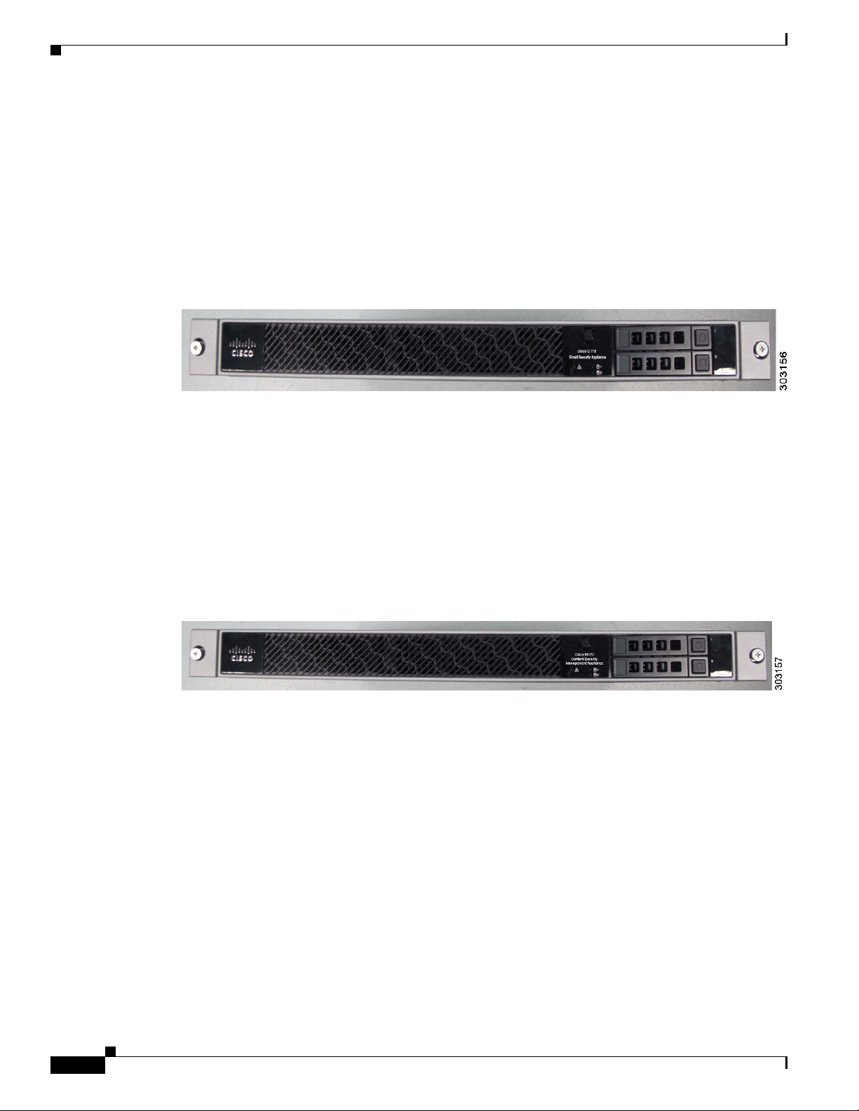
Cisco C170 Email Security Appliance
Cisco C170 Email Security Appliance (Cisco C170) automatically stops spam, viruses, and other
anomalies. It prevents and responds to multilevel threats and includes capabilities such as: spam and
virus defense, policy enforcement, email authentication, and centralized and built-in GUI management
tools. For information on Cisco C170, see:
http://www.cisco.com/en/US/products/ps10154/tsd_products_support_series_home.html
Figure 1-1 shows the Cisco C170 front panel view.
Figure 1-1 Cisco C170 Email Security Appliance
Chapter
Cisco M170 Content Security Management Appliance
Cisco M170 Content Security Management Appliance (Cisco M170) is a central platform for managing
all policy, integrated reporting on traffic data, and email auditing information for the Cisco 170 series
appliances. For information on Cisco M170, see:
http://www.cisco.com/en/US/partner/products/ps10155/tsd_products_support_series_home.html
Figure 1-2 shows the Cisco M170 front panel view.
Figure 1-2 Cisco M170 Content Security Management Appliance
Cisco S170 Web Security Appliance
Cisco S170 Web Security Appliance (Cisco S170) is a secure web gateway that combines advanced
malware protection, application visibility and control (AVC), acceptable use policy controls, insightful
reporting, and secure mobility on a single platform. It is a single platform for administrators to set
security policy, control applications at a granular level, and get visibility into web traffic trends at
organizations and for remote and mobile users. For information on Cisco S170, see:
http://www.cisco.com/en/US/partner/products/ps10164/tsd_products_support_series_home.html
1-2
Cisco 170 Series Hardware Installation Guide
OL-28365-01
Page 15
Chapter
Cisco S170
Web Security Appliance
1
2
!
Figure 1-3 shows the Cisco S170 front panel view.
Figure 1-3 Cisco S170 Web Security Appliance
Cisco 170 Series Appliance Panels
This section describes the front and rear Cisco 170 series appliance panels. It includes the following
topics:
• Front Panel LEDs, page 1-3
• Rear Panel LEDs, page 1-5
• Rear Panel Ports, page 1-6
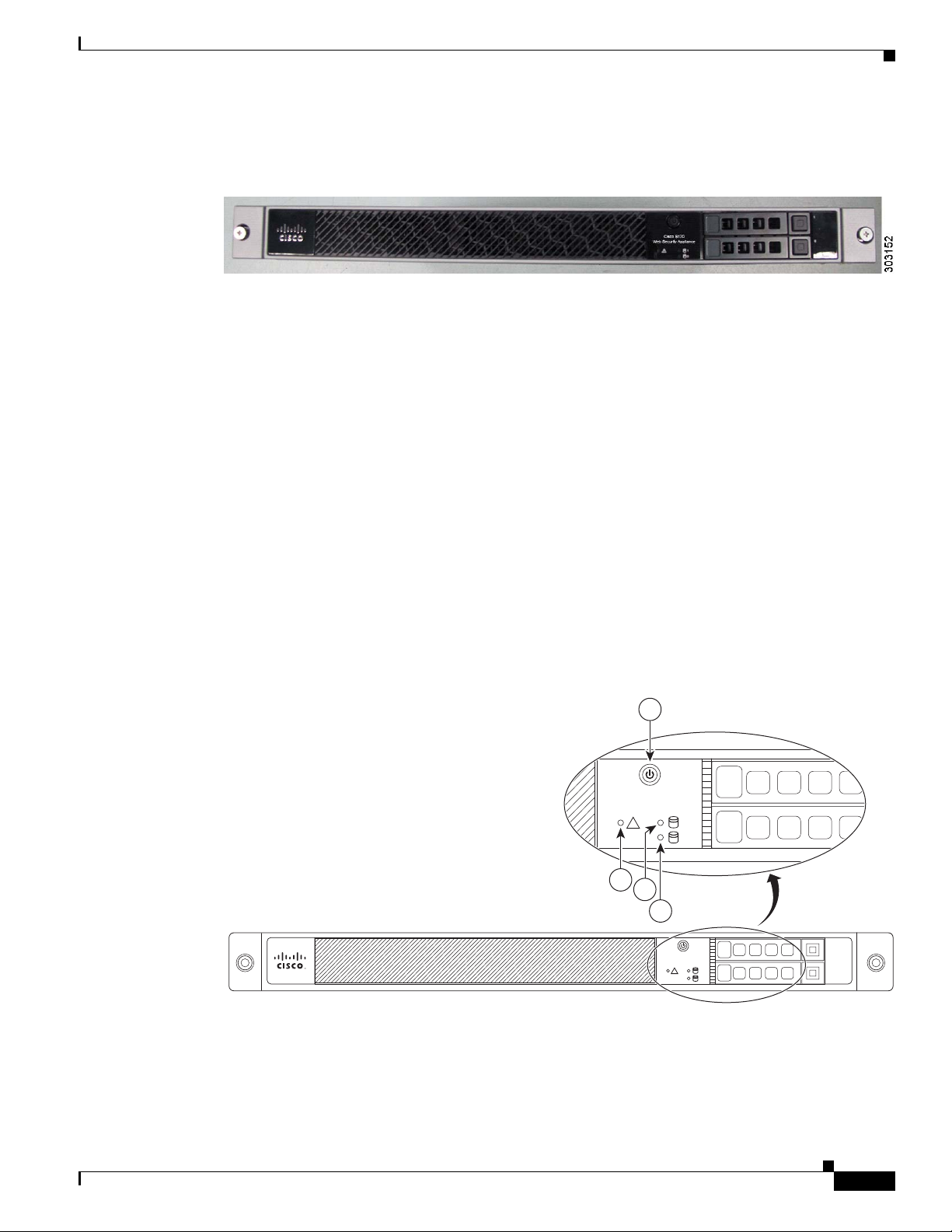
Front Panel LEDs
This section describes the front panel LEDs for the Cisco 170 series appliance.
Figure 4 shows the front panel LEDs that are available for the Cisco C170, Cisco M170 and Cisco S170
models (graphic shows the Cisco S170 bezel).
Figure 4 Front Panel LEDs for Cisco C170, Cisco M170 and Cisco S170
1
2
3
4
Cisco S170
Web Security Appliance
!
1
2
1
0
OL-28365-01
303134
Cisco 170 Series Hardware Installation Guide
1-3
Page 16

Chapter
LED Description
1 Power button A hard switch that turns the system on and off. Once depressed, the
button stays in the “on” position:
• On—The power symbol on the button illuminates.
• Off—The power symbol on the button is dark.
2
Alarm Indicates system operating status:
• Off—Normal operating system function.
• Solid amber—Critical Alarm indicating one or more of the
following:
–
A major failure of a hardware or software component.
–
An over-temperature condition.
–
The power voltage is outside of the tolerance range.
See the “Alarm LED” section on page 1-8.
3 HD1 Indicates Hard Disk Drive 1 status:
• Flashing green—Proportioned to read/write activity.
• Solid amber—Hard disk drive failure.
• Flashing amber—Hard disk drive being rebuilt.
• Off—No hard disk drive present.
4
HD0 Indicates Hard Disk Drive 0 status:
• Flashing green—Proportioned to read/write activity.
• Solid amber—Hard disk drive failure.
• Flashing amber—Hard disk drive being rebuilt.
• Off—No hard disk drive present.
1-4
Cisco 170 Series Hardware Installation Guide
OL-28365-01
Page 17

Chapter
Rear Panel LEDs
This section describes the rear panel LEDs for the Cisco 170 series appliance.
Figure 1-5 shows the rear panel LEDs that are available for the Cisco C170, Cisco M170 and Cisco S170
models (graphic shows the Cisco S170 rear panel).
Figure 1-5 Rear Panel LEDs for Cisco C170, Cisco M170 and Cisco S170
1 4
2 3
LED Description
1 Power Indicates power supply status:
• Off—Power supply off.
• Solid green—Power supply on.
2
Alarm Indicates system operating status:
• Off—Normal operating system function.
• Solid amber—Critical Alarm indicating one or more of the
following:
–
A major failure of a hardware or software component.
–
An over-temperature condition.
–
The power voltage is outside of the tolerance range.
See the “Alarm LED” section on page 1-8.
303135
OL-28365-01
Cisco 170 Series Hardware Installation Guide
1-5
Page 18

3 HD0 Indicates Hard Disk Drive 0 status:
4
Rear Panel Ports
Chapter
LED Description
• Flashing green—Proportioned to read/write activity.
• Solid amber—Hard disk drive failure.
• Flashing amber—Hard disk drive being rebuilt.
• Off—No hard disk drive present.
HD1 Indicates Hard Disk Drive 1 status:
• Flashing green—Proportioned to read/write activity.
• Solid amber—Hard disk drive failure.
• Flashing amber—Hard disk drive being rebuilt.
• Off—No hard disk drive present.
This section describes the rear panel ports on the Cisco 170 series appliance.
Figure 1-6 and Figure 1-7 show the rear panel and ports that are available on the Cisco S170 model.
Figure 1-6 Rear Panel and Ports for Cisco S170
Figure 1-7 Rear Panel Ports for Cisco S170
1
45
3
1-6
303136
2
Cisco 170 Series Hardware Installation Guide
OL-28365-01
Page 19

Chapter
.
LED Description
1 Management interface Indicates the Gigabit Ethernet interface that is restricted to
management use only. Connect with an RJ-45 cable.
See the “Management Interface” section on page 1-8.
2 Power supply Indicates the appliance power supply.
3 RJ-45 ports Indicates the Gigabit Ethernet customer data interfaces.
The port numbers are (from left to right) P1, P2, T1 and T2.
4 USB Ports
1
Indicates the two USB standard ports.
5 Console port Indicates the console port that directly connects a computer to the
Cisco 170 series.
1. USB ports can be used in future software releases.
Figure 1-8 and Figure 1-9 show the rear panel and ports that are available on the Cisco C170 and
Cisco M170 models.
Figure 1-8 Rear Panel and Ports for Cisco C170 and Cisco M170
Figure 1-9 Rear Panel Ports for Cisco C170 and Cisco M170
34
2
303137
OL-28365-01
1
LED Description
1 Power supply Indicates the appliance power supply.
Cisco 170 Series Hardware Installation Guide
1-7
Page 20

Alarm LED
Chapter
2 RJ-45 ports Indicates the Gigabit Ethernet customer data interfaces.
The port numbers are (from left to right) Data 1 and Data 2.
3 USB Ports
4 Console port Indicates the console port that directly connects a computer to the
1. USB ports can be used in future software releases.
The Cisco 170 series appliance performs autonomous environment monitoring to poll all external
sensors and monitor operating conditions. In the event of damage to certain internal components or
surpassed temperature thresholds, the system activates an alarm LED to notify you of a critical
condition. For example, the alarm LED is activated by firmware in the event of various critical
over-voltage and over-temperature conditions, as well as when the Cisco 170 series appliance has
missing or unrecognized internal chip components. When the alarm LED lights, contact Cisco Technical
Support to find out the cause of the problem. See the
page 4-3 for more information.
1
Indicates the two USB standard ports.
Cisco 170 series appliance.
“Contacting Service and Support” section on
Management Interface
By default, the management interface is used to administer Cisco S170 and monitor Web Proxy (data)
traffic. However, you can configure the management port for management use only.
You may want to do this if your organization uses a separate management network. This can increase
security by ensuring no proxy traffic can reach Cisco S170 on the management interface.
When you use the management interface for management traffic only, you must configure at least one
data interface for proxy traffic and define different routes for management and data traffic.
For information about configuring and using the management port to set up and manage Cisco S170, see
Cisco IronPort AsyncOS 7.5.0 User Guide for Web Security Appliances:
http://www.cisco.com/en/US/docs/security/wsa/wsa7.5/user_guide/WSA_7.5.0_UserGuide.pdf.
Hard Disk Drives
Two hard disk drives (HDDs) in a RAID 1 configuration are pre-installed in the Cisco 170 series
appliance. The HDDs are hot-swappable. For information on removing and replacing HDDs, see the
“Replacing the Hard Disk Drives” section on page 4-2.
1-8
Cisco 170 Series Hardware Installation Guide
OL-28365-01
Page 21

Chapter
Hardware and Technical Specifications
Table 1-1 contains hardware and technical specifications for the Cisco 170 series.
Table 1-1 Hardware and Technical Specifications for Cisco C170, Cisco M170 and Cisco S170
Specifications Cisco C170 Cisco M170 Cisco S170
Physical Specifications
Form-factor 1 RU, 14-in 1 RU, 14-in 1 RU, 14-in
Rack mountable Yes
Slide rails (standard)
Brackets (spares)
Dimensions 1.67 x 16.9 x 15.5 in.
42.4x429x395 mm
Total Weight 26.96 lb. 26.96 lb. 26.96 lb.
Power Supply Information
Power supply 400 watts, 100/240V 400 watts, 100/240V 400 watts, 100/240V
Redundant power supply Not available Not available Not available
Processor, Memory, and Disks
CPUs 1x2 (1 Dual Core) 1x2 (1 Dual Core) 1x2 (1 Dual Core)
Memory 4 GB 4 GB 4 GB
Disk Space and Count 250 GB, RAID 1 250 GB, RAID 1 250 GB, RAID 1
Hot Swappable Hard Disk
Drives
RAID Level and Controller RAID 1, Software RAID 1, Software RAID 1, Software
Interfaces
Ethernet 2 Gigabit NICs, RJ-45 2 Gigabit NICs, RJ-45 4 Gigabit NICs, RJ-45
Speed (mbps) 10/100/1000, Auto-Negotiate 10/100/1000, Auto-Negotiate 10/100/1000,
Duplex Half or Full, Auto-Negotiate Half or Full, Auto-Negotiate Half or Full, Auto-Negotiate
Serial 1xRS-232 (RJ-45) 1xRS-232 (RJ-45) 1xRS-232 (RJ-45)
Fiber No No No
1
USB
Operating Conditions
Tem p e r a ture -5°C to 45°C
Relative humidity 20% to 80% (noncondensing) 20% to 80% (noncondensing) 20% to 80%
Altitude 3,000 ft. 3,000 ft. 3,000 ft.
Vibratio n 0.41Grms, at 3Hz-500Hz 0.41Grms, at 3Hz-500Hz 0.41Grms, at 3Hz-500Hz
Configuration, Logging, and Monitoring
Web Interface GUI-based (HTTPS) GUI-based (HTTPS) GUI-based (HTTPS)
Yes Yes Yes
2 2 2
(23°F to 104°F)
Yes
Slide rails (standard)
Brackets (spares)
1.67 x 16.9 x 15.5 in.
42.4x429x395 mm
-5°C to 45°C
(23°F to 104°F)
Yes
Slide rails (standard)
Brackets (spares)
1.67 x 16.9 x 15.5 in.
42.4x429x395 mm
Auto-Negotiate
-5°C to 45°C
(23°F to 104°F)
(noncondensing)
OL-28365-01
Cisco 170 Series Hardware Installation Guide
1-9
Page 22

Chapter
Table 1-1 Hardware and Technical Specifications for Cisco C170, Cisco M170 and Cisco S170 (Continued)
Specifications Cisco C170 Cisco M170 Cisco S170
Command Line Interface SSH or Telnet (command
based)
SSH or Telnet (command
based)
SSH or Telnet (command
based)
Logging Syslog Squid, Apache, Syslog, W3C Squid, Apache, Syslog
Centralized Reporting Supported Supported Supported
File Transfer SCP, FTP SCP, FTP SCP, FTP
Configuration Files XML-based XML-based XML-based
Centralized Configuration Supported Supported Supported
Monitoring SNMPv1-3, email alerts SNMPv1-3, email alerts SNMPv1-3, email alerts
Environmental Operating Ranges
Total Current (A) 4.85 (max) 4.85 (max) 4.85 (max)
Input Voltage (V) 100 to 240 VAC 100 to 240 VAC 100 to 240 VAC
Operating Power (W) 400 (max) 400 (max) 400 (max)
Total Heat Dissipation
432.6 432.6 432.6
(BTU/Hr)
Leakage Current (mA) 3.5 3.5 3.5
Fan Exhaust Volume (CFM) Idle at 24°C: 12.3
Full fan speed: 34.4
Ambience Noise (bels) Idle: 41.3 dBa
Stress: 64.2 dBa max.
Idle at 24°C: 12.3
Full fan speed: 34.4
Idle: 41.3 dBa
Stress: 64.2 dBa max.
Idle at 24°C: 12.3
Full fan speed: 34.4
Idle: 41.3 dBa
Stress: 64.2 dBa max.
Effective MTBF (Hours) 107,356 107,356 107,356
Non-Operating Conditions
Tem p e r a ture -25°C to 70°C
(-13°F to 158°F)
-25°C to 70°C
(-13°F to 158°F)
-25°C to 70°C
(-13°F to 158°F)
Relative humidity 5% to 95% (noncondensing) 5% to 95% (noncondensing) 5% to 95% (noncondensing)
Altitude (m) 4,570 4,570 4,570
Vibratio n 1.12Grms at 3Hz-500Hz 1.12Grms at 3Hz-500Hz 1.12Grms at 3Hz-500Hz
Industry Certifications
RoHS Yes Yes Yes
Other Certifications Safety: cULus, CB, CCC,
BSMI
EMC: CE, FCC, VCCI,
CTICK, KC
1. USB ports can be used in future software releases.
Safety: cULus, CB, CCC,
BSMI
EMC: CE, FCC, VCCI,
CTICK, KC
Safety: cULus, CB, CCC,
BSMI
EMC: CE, FCC, VCCI,
CTICK, KC
1-10
Cisco 170 Series Hardware Installation Guide
OL-28365-01
Page 23

Preparing for Installation
This chapter describes the steps to follow before installing the Cisco 170 series appliance or performing
hardware maintenance. It includes the following sections:
• Installation Overview, page 2-1
• Safety Recommendations, page 2-2
• General Site Requirements, page 2-4
Installation Overview
To prepare for the installation of the Cisco 170 series appliance, perform the following steps:
Step 1 Review the safety precautions outlined in the Safety and Compliance Guide for the Cisco Content
Security Appliances and follow proper safety procedures when performing any tasks in this guide. See:
http://www.cisco.com/en/US/docs/security/esa/hw/SafetyAndComplianceGuide.pdf.
Step 2 Read the appropriate release notes for the Cisco C170 Email Security Appliance (Cisco C170), Cisco
M170 Content Security Management Appliance (Cisco M170), and Cisco S170 Web Security Appliance
(Cisco S170) appliances.
CHAP T ER
2
OL-28365-01
Step 3 Unpack the appliance and the accessory kit that accompanies it.
Step 4 Place the appliance on a stable work surface.
Step 5 Mount the appliance with the provided slide rails using the information in the “Installing the Cisco 170
Series Appliance with Slide Rails” section on page 3--1.
Note Optionally, you can also mount the appliance in a rack using the information in the “Rack
Mounting the Cisco 170 Series Appliance” section on page 3-8.
Step 6 Establish network connectivity using the information in the “Connecting the Interface Cables and
Verifying Connectivity” section on page 3-10.
Step 7 For additional information on pre-installation and post-installation tasks, see the following Hardware
Quick Start Guides:
• Cisco C170 Email Security Appliance Quick Start Guide:
http://www.cisco.com/en/US/docs/security/esa/hw/C170_QSG.pdf
Cisco 170 Series Hardware Installation Guide
2-1
Page 24

• Cisco M170 Content Security Management Appliance Quick Start Guide:
http://www.cisco.com/en/US/docs/security/security_management/sma/hw/quick_start/M170_QSG
.pdf
• Cisco S170 Web Security Appliance Quick Start Guide:
http://www.cisco.com/en/US/docs/security/wsa/hw/S170_QSG.pdf
Safety Recommendations
Use the following guidelines and the information in the following sections to help ensure your safety and
protect the Cisco 170 series appliance. The list of guidelines may not address all potentially hazardous
situations in your working environment, so be alert and exercise good judgement at all times.
Note Removing and replacing the hard disk drives (HDDs) in the appliance as described in “Removing and
Installing Hard Disk Drives” section on page 4-1 does not affect your Cisco warranty.
Chapter
Observe the following safety guidelines:
• Keep the appliance area clear and dust-free before, during, and after installation.
• Keep tools away from walk areas in which you and others might fall over them.
• Do not wear loose clothing or jewelry, such as earrings, bracelets, or chains that could get caught in
the appliance.
• Wear safety glasses if you are working under any conditions that might be hazardous to your eyes.
• Do not perform any action that creates a potential hazard to people or makes the equipment unsafe.
• Never attempt to lift an object that is too heavy for one person to handle.
This section includes the following topics:
• Maintaining Safety with Electricity, page 2-2
• Preventing Electrostatic Discharge Damage, page 2-3
• Working in an ESD Environment, page 2-3
Maintaining Safety with Electricity
Warning
Before working on a chassis or working near power supplies, unplug the power cord on AC units.
Statement 12
2-2
Follow these guidelines when working on equipment powered by electricity:
• Locate the emergency power-off switch for the room in which you are working. If an electric
accident occurs, you can quickly turn off the power.
• Do not work alone if potentially hazardous conditions exist anywhere in your work space.
• Never assume that power is disconnected from a circuit; always check the circuit.
• Look carefully for possible hazards in your work area, such as moist floors, ungrounded power
extension cables, frayed power cords, and missing safety grounds.
Cisco 170 Series Hardware Installation Guide
OL-28365-01
Page 25

Chapter
• If an electrical accident occurs, proceed as follows:
–
Use caution; do not become a victim yourself.
–
Disconnect power from the system.
–
If possible, send another person to get medical aid. Otherwise, assess the condition of the
victim, and then call for help.
–
Determine whether or not the person needs rescue breathing or external cardiac compressions;
then take appropriate action.
• Use the Cisco 170 series appliance within its marked electrical ratings and product usage
instructions.
• Install the Cisco 170 series appliance in compliance with local and national electrical codes as listed
in the Safety and Compliance Guide for the Cisco Content Security Appliances document.
• The Cisco 170 series appliance is equipped with AC-input power supplies and is shipped with a
3-wire electrical cord with a grounding-type plug that fits into a grounding-type power outlet only.
Do not circumvent this safety feature. Equipment grounding should comply with local and national
electrical codes.
Preventing Electrostatic Discharge Damage
Electrostatic discharge (ESD) can damage equipment and impair electrical circuitry. ESD damage occurs
when electronic components are improperly handled and can result in complete or intermittent failures.
• Always follow ESD-prevention procedures when removing and replacing components. Ensure that
the appliance is electrically connected to an earth ground. Wear an ESD-preventive wrist strap,
ensuring that it makes good skin contact. Connect the grounding clip to an unpainted surface of the
appliance frame to safely ground ESD voltages. To properly guard against ESD damage and shocks,
the wrist strap and cord must operate effectively. If no wrist strap is available, ground yourself by
touching the metal part of the appliance.
• For safety, periodically check the resistance value of the antistatic strap, which should be between
1 and 10 megohms (Mohms).
Working in an ESD Environment
• Electrostatic discharge (ESD) can damage equipment and impair electrical circuitry. ESD damage
occurs when electronic components are improperly handled and can result in complete or
intermittent failures. Always follow ESD-prevention procedures when you remove and replace
components. Ensure that the appliance is electrically connected to earth ground. Wear an
ESD-preventive wrist strap, ensuring that it makes good skin contact. Connect the grounding clip to
an unpainted surface of the appliance frame to safely ground unwanted ESD voltages. To guard
against ESD damage and shocks, the wrist strap and cord must operate properly. If no wrist strap is
available, ground yourself by touching the metal part of the appliance.
OL-28365-01
Cisco 170 Series Hardware Installation Guide
2-3
Page 26

General Site Requirements
The topics in this section describe the requirements your site must meet for safe installation and
operation of your Cisco 170 series system. Ensure that your site is properly prepared before beginning
installation.
This section includes the following topics:
• Site Environment, page 2-4
• Preventive Site Configuration, page 2-4
• Power Supply Considerations, page 2-5
• Configuring Equipment Racks, page 2-7
Site Environment
Place the appliance on a desktop or mount it on a rack. The location of the appliance and the layout of
the equipment rack or wiring room are extremely important for proper system operation. Placing
equipment too close together with inadequate ventilation and inaccessible panels can cause system
malfunctions and shutdowns. Improper placement can also make it difficult for you to access the
appliance for maintenance.
Chapter
For information about physical specifications, see the “Hardware and Technical Specifications” section
on page 1-9.
When planning the site layout and equipment locations, keep in mind the precautions described in the
next section “
possibility of environmentally caused shutdowns. If you are currently experiencing shutdowns or
unusually high error rates with your existing equipment, these precautions may help you isolate the
cause of failures and prevent future problems.
Preventive Site Configuration, page 2-4,” to help avoid equipment failures and reduce the
Preventive Site Configuration
The following precautions will help plan an acceptable operating environment for the appliance and
avoid environmentally caused equipment failures:
• Electrical equipment generates heat. Ambient air temperature might not be adequate to cool
equipment to acceptable operating temperatures without adequate circulation. Ensure that the room
in which you operate your system has adequate air circulation.
• Always follow the ESD-prevention procedures described previously to avoid damage to equipment.
Damage from static discharge can cause immediate or intermittent equipment failure.
• Ensure that the appliance cover is secure. The appliance is designed to allow cooling air to flow
effectively within it. An open appliance allows air leaks, which may interrupt and redirect the flow
of cooling air from the internal components.
2-4
Cisco 170 Series Hardware Installation Guide
OL-28365-01
Page 27

Chapter
354
120
356
120
357
Power Supply Considerations
The Cisco 170 series hardware operates on AC power and supports the ability to restore the previous
power state of the system in the event that AC power is lost. Be aware of the following when interacting
with system hardware:
• The Cisco 170 series appliance requires 50 seconds from the time that AC power is applied before
the power state can be updated and stored. This means that any changes to the power state within
the first 50 seconds of applying AC power will not be observed if AC power is removed within that
time.
• The Cisco 170 series appliance requires 10 seconds from the time it is placed into standby mode
before the power state can be updated and stored. This means any changes to the power state within
the first 10 seconds of entering standby mode (including the standby mode itself) will not be
observed if AC power is removed within that time.
Observe the following considerations:
• Check the power at the site before installing the appliance to ensure that the power is “clean” (free
of spikes and noise). Install a power conditioner, if necessary, to ensure proper voltages and power
levels in the source voltage.
• Install proper grounding for the site to avoid damage from lightning and power surges.
• The Cisco 170 series appliance does not have a user-selectable operating range. Refer to the label
on the appliance for the correct AC-input power requirement.
• Several styles of AC-input power supply cords are available; make sure that you have the correct
style for your site.
• Install an uninterruptible power source for your site, if possible.
You also need to provide power to the switch with the appropriate AC power cord for your location.
Table 2-1 lists the power cords that are used with the AC power supply.
Table 2-1 AC-Input Power Cord Options
Locale Part Number Length Plug Rating Plug Type
Appliance Coupler
300 W AC Power Supply
North America CAB-AC (72-0259) 8.2 ft (2.5 m) 125 VAC, 10 A
Australia, CAB-ACA
8.2 ft (2.5 m) 250 VAC, 10 A
(72-0746-01)
OL-28365-01
Europe (except
Italy)
CAB-ACE (72-0460) 8.2 ft (2.5 m) 250 VAC, 10 A
Cisco 170 Series Hardware Installation Guide
2-5
Page 28
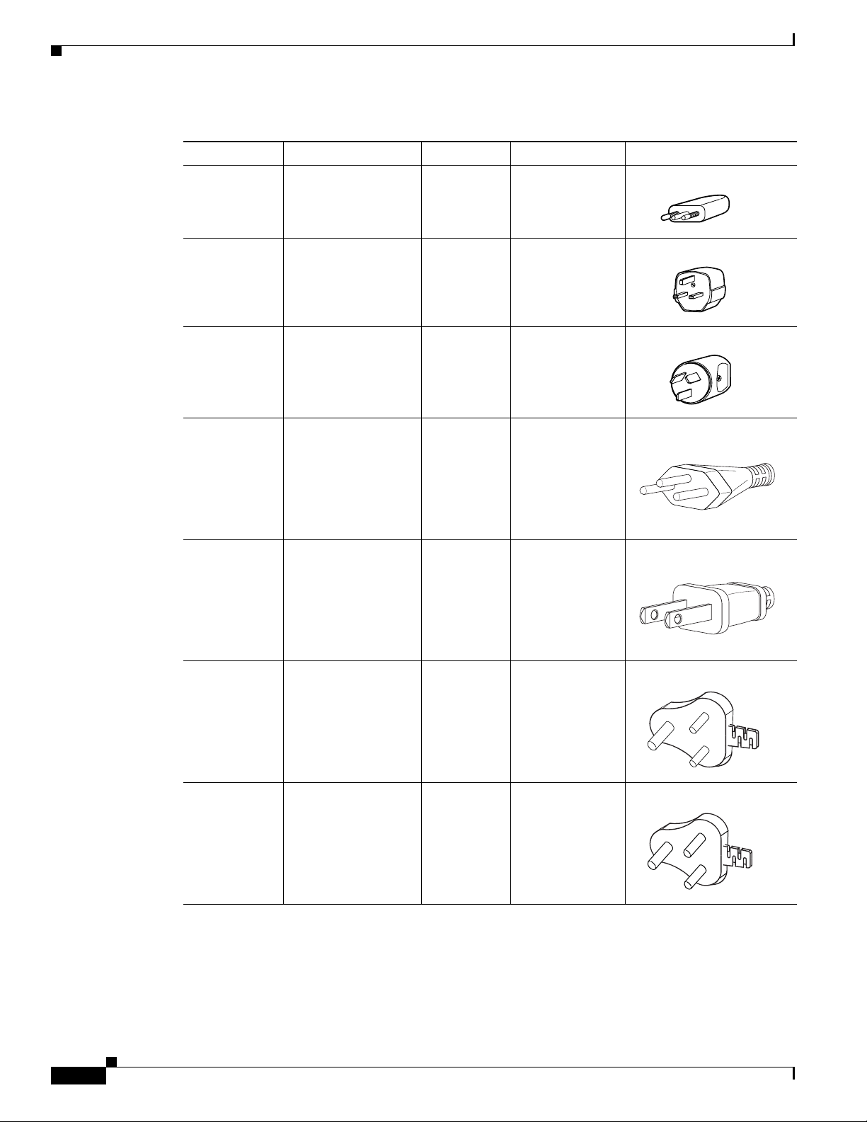
Table 2-1 AC-Input Power Cord Options (Continued)
120358
120359
120356
251248
Locale Part Number Length Plug Rating Plug Type
Italy CAB-ACI 72-0556 8.2 ft (2.5 m) 250 VAC, 10 A
Chapter
Singapore
CAB-ACU 72-0557 8.2 ft (2.5 m) 250 VAC, 10 A
United
Kingdom
Argentina CAB-ACR
(37-0995-01)
Switzerland CAB-ACS
(72-1483-01)
Japan CAB-JPN
(72-1925-01)
8.2 ft (2.5 m) 250 VAC, 10 A
8.2 ft (2.5 m) 250 VAC, 10 A
251247
8.2 ft (2.5 m) 250 VAC, 10 A
2-6
India CAB-IND-10A
(37-0863-01)
South Africa AIR-PWR-CORD-S
A
(37-0346-01)
Cisco 170 Series Hardware Installation Guide
8.2 ft (2.5 m) 250 VAC, 10 A
331705
8.2 ft (2.5 m) 250 VAC, 10 A
331706
OL-28365-01
Page 29

Chapter
Configuring Equipment Racks
The following tips help you plan an acceptable equipment rack configuration:
• Enclosed racks must have adequate ventilation. Ensure that the rack is not overly congested because
each appliance generates heat. An enclosed rack should have louvered sides and a fan to provide
cooling air.
• When mounting a appliance in an open rack, ensure that the rack frame does not block the intake or
exhaust ports. If the appliance is installed on slides, check the position of the appliance when it is
seated all the way into the rack.
• In an enclosed rack with a ventilation fan in the top, excessive heat generated by equipment near the
bottom of the rack can be drawn upward and into the intake ports of the equipment above it in the
rack. Ensure that you provide adequate ventilation for equipment at the bottom of the rack.
• Baffles can help to isolate exhaust air from intake air, which also helps to draw cooling air through
the appliance. The best placement of the baffles depends on the airflow patterns in the rack.
Experiment with different arrangements to position the baffles effectively.
OL-28365-01
Cisco 170 Series Hardware Installation Guide
2-7
Page 30

Chapter
2-8
Cisco 170 Series Hardware Installation Guide
OL-28365-01
Page 31

CHAP T ER
3
Installing and Connecting the Cisco 170 Series Appliance
This chapter describes how to install the Cisco 170 series (Cisco 170 series) appliance using slide rails
(standard configuration) or rack-mounting it (optional configuration) and provides information on how
to connect the interface cables.
It includes the following sections:
• Installing the Cisco 170 Series Appliance with Slide Rails, page 3--1
• Rack Mounting the Cisco 170 Series Appliance, page 3-8
• Connecting the Interface Cables and Verifying Connectivity, page 3-10
Installing the Cisco 170 Series Appliance with Slide Rails
To install the Cisco 170 series using slide rails, perform the steps in this section.
This section includes the following topics:
• Verifying the Box Contents, page 3--1
• Disassembling the Slide Rail, page 3-0
• Attaching Inner Rails to the Appliance, page 3-1
• Verifying the Rack Type, page 3-2
• Securing Round Hole Racks, page 3-3
• Securing Threaded Hole Racks, page 3-3
• Attaching the Outer Slide Rail to Round and Square Hole Racks, page 3-4
• Attaching the Outer Slide Rail to Threaded Hole Racks, page 3-5
• Installing the Appliance, page 3-6
• Securing the Appliance, page 3-7
Verifying the Box Contents
Step 1 Remove the contents from the box and verify that it contains the following items for all rack types (see
Figure 3-1):
OL-28365-01
Cisco 170 Series Hardware Installation Guide
3--1
Page 32

• A—Slide rails (x2) (preconfigured for square hole racks)
• B— Phillips flat-head screws for Inner Slide (x2)
For round hole racks, you also need the following:
• C—Round hole inserts (x4)
• Phillips screwdriver
For threaded hole racks, you also need the following:
• D—Threaded hole brackets (x2)
• E—Threaded hole standoffs (x2)
• F—Phillips pan-head screws for threaded hole racks (x8)
• Flat-head screwdriver
Figure 3-1 Appliance Box Contents
A
Chapter
B C D E F
Note By default, the slide rails are shipped with the appliance. If you have a 2-post rack, you can order rack
mounts, which are available as spares for the Cisco 170 series appliance.
Disassembling the Slide Rail
Step 1 Pull the inner slide rail from the outer slide rail.
300885
3-0
Cisco 170 Series Hardware Installation Guide
OL-28365-01
Page 33

Chapter
330907
Front
Step 2 Slide the plastic tab forward, and pull the inner slide rail to disconnect it from the outer slide rail.
Step 3 Repeat the previous steps for the other slide rail.
Attaching Inner Rails to the Appliance
Step 1 Align one of the inner slide rail key holes over the appliance shoulder screw on one side. Slide the inner
slide rail forward so that the shoulder screw is securely in place.
330908
OL-28365-01
Cisco 170 Series Hardware Installation Guide
3-1
Page 34

Chapter
330903
Step 2 Use a Phillips screwdriver to secure the inner slide rail with one Phillips flat-head screw (See B in
Figure 3-1).
330905
Step 3 Secure the other inner slide rail to the appliance by repeating the previous steps.
Verifying the Rack Type
Step 1 The slide rails are pre-assembled for square hole racks. Use the following steps for the different rack
types:
• For square hole racks, see the “Attaching the Outer Slide Rail to Round and Square Hole Racks”
section on page 3-4.
• For round hole racks, see the “Securing Round Hole Racks” section on page 3-3.
• For threaded hole racks, see the “Securing Threaded Hole Racks” section on page 3-3.
The following figure shows the slide rail with square hole rack inserts.
330904
3-2
Cisco 170 Series Hardware Installation Guide
OL-28365-01
Page 35

Chapter
330884
Securing Round Hole Racks
Step 1 Using a Phillips head screwdriver, remove the square insert from the rear of the rail. Retain the two
Phillips head screws.
Step 2 Remove the square insert from the front of the rail. Retain the two Phillips head screws.
330882
Step 3 Align the round hole insert (see C in Figure 3-1) to the rear of the rail, and secure it with two of the saved
screws.
330881
Step 4 Align the round hole insert (see C in Figure 3-1) to the front of the rail over the hooks, and secure it with
two of the saved screws.
330880
Step 5 Proceed to the “Attaching the Outer Slide Rail to Round and Square Hole Racks” section on page 3-4.
Securing Threaded Hole Racks
Step 1 Using a Phillips head screwdriver, remove the square hole insert from the rear of the rail.
OL-28365-01
Cisco 170 Series Hardware Installation Guide
3-3
Page 36

Chapter
330884
Step 2 Remove the square hole insert from the front of the rail.
330882
Step 3 Align the threaded hole bracket (see D in Figure 3-1) to the front of the rail over the hooks. Secure it
with the threaded hole standoff (see E in Figure 3-1) using a flat-head screwdriver.
Step 4 No additional hardware is necessary for the rear adapter.
330876
Step 5 Repeat the previous steps page for the other slide rail.
Step 6 Proceed to the “Attaching the Outer Slide Rail to Threaded Hole Racks” section on page 3-5.
Attaching the Outer Slide Rail to Round and Square Hole Racks
Step 1 Align the front of one of the outer slide rails with the rack upright, push it forward, and click it into place.
Align the rear of the outer slide rail with the rack upright, pull the release tab, push the slide rail toward
the rack, release the tab, and click it into place.
Note For racks shorter than 24 inches in depth, remove the rear bracket with a Phillips head screwdriver, pull
the release tab, and adjust the slide rail to the appropriate length for the rack.
3-4
Cisco 170 Series Hardware Installation Guide
OL-28365-01
Page 37

Chapter
Front of
Rack
Rear of
Rack
Rear of
Bracket
330901
Step 2 Secure the other outer slide rail to the rack by repeating the previous steps.
330872
Step 3 Proceed to the “Installing the Appliance” section on page 3-6.
Attaching the Outer Slide Rail to Threaded Hole Racks
Step 1 Align the slide rail to the front rack post. Secure it with two of the included Phillips pan-head screws
(see F in Figure 3-1).
330883
OL-28365-01
Cisco 170 Series Hardware Installation Guide
3-5
Page 38

Chapter
Step 2 Align the slide rail to the rear rack post. Secure it with two of the included Phillips pan-head screws (see
F in Figure 3-1).
330875
Step 3 Align the other slide rail to the rack by repeating the previous steps.
Step 4 Proceed to the “Installing the Appliance” section on page 3-6.
Installing the Appliance
Step 1 Align the inner slide rails to the outer slide rails. Install the inner slide rails into the outer slide rails until
they lock into place.
330889
3-6
Cisco 170 Series Hardware Installation Guide
OL-28365-01
Page 39

Chapter
Step 2 Pull the side release tabs to unlock the inner slide rail and push the appliance assembly into the rack.
Securing the Appliance
Step 1 Secure the appliance to the rack with the front captive screws.
330898
330890
OL-28365-01
Cisco 170 Series Hardware Installation Guide
3-7
Page 40

Rack Mounting the Cisco 170 Series Appliance
If you have 2-post racks, you can order the rack mount spares to rack-mount the Cisco 170 series
appliance as described in this section.
This section contains the following topics:
• Guidelines and Recommendations, page 3-8
• Rack Mounting the Cisco C170, Cisco M170, or Cisco S170 Appliances, page 3-8
Guidelines and Recommendations
Chapter
Warning
To prevent bodily injury when mounting or servicing this unit in a rack, you must take special
precautions to ensure that the system remains stable. The following guidelines are provided to ensure
your safety:
this unit in a partially filled rack, load the rack from the bottom to the top with the heaviest component at the bottom
of the rack.If the rack is provided with stabilizing devices, install the stabilizers before mounting or servicing the unit
in the rack.
The following information can help plan equipment rack installation:
• Allow clearance around the rack for maintenance.
• If the rack contains stabilizing devices, install the stabilizers prior to mounting or servicing the unit
in the rack.
• When mounting a device in an enclosed rack, ensure adequate ventilation. Do not overcrowd an
enclosed rack.
• When mounting a device in an open rack, make sure that the rack frame does not block the intake
or exhaust ports.
• If the rack contains only one unit, mount the unit at the bottom of the rack.
• If the rack is partially filled, load the rack from the bottom to the top, with the heaviest component
at the bottom of the rack.
This unit should be mounted at the bottom of the rack if it is the only unit in the rack.When mounting
Statement 1006
Make sure that the rack is not congested, because each unit generates heat.
Rack Mounting the Cisco C170, Cisco M170, or Cisco S170 Appliances
3-8
To install the Cisco C170, Cisco M170, or Cisco S170 appliances in a rack perform the following steps:
Step 1 Remove the preinstalled die-cast brackets on either side of the appliance by removing the three screws
that hold each bracket in place. See Figure 3-2.
Cisco 170 Series Hardware Installation Guide
OL-28365-01
Page 41

Chapter
Figure 3-2 Removing Preinstalled Die-Cast Brackets on Either Side of the Appliance
Step 2 Install a fixed rack-mount bracket to both sides of the appliance by aligning the screw holes on the
appliance to the slots and holes on the bracket. The bracket will be set back from the front faceplate
(bezel). Secure each bracket with three screws. See Figure 3-3.
Figure 3-3 Attaching the Rack-Mount Brackets
Step 3 Install the appliance with the front bezel facing the cold aisle so that air flows from front to back. See
Figure 3-4.
OL-28365-01
Cisco 170 Series Hardware Installation Guide
3-9
Page 42

Figure 3-4 Attaching the C170, M170, or S170 Appliance to the Rack
330840
Cisco ASA 5545
Adapative Security Appliance
BOOT
ACTIVE
PS1
PS0
ALARM
VPN
HD1
HD0
1
0
COLD AISLE
Front Bezel
HOT AISLE
AIR FLOW DIRECTION
Rear I/O
Chapter
Connecting the Interface Cables and Verifying Connectivity
This section describes how to connect the cables to the Console, Auxiliary, and Management ports.
Warning
Caution Read the safety warnings in the Safety and Compliance Guide for the Cisco Content Security Appliances
Step 1 Place the appliance on a flat, stable surface, or in a rack (if you are rack-mounting it).
Step 2 Before connecting a computer or terminal to the ports, determine the baud rate of the serial port. The baud
Step 3 Connect the cables to the ports.
Only trained and qualified personnel should install, replace, or service this equipment. Statement 49
and follow proper safety procedures when performing any tasks in this document. See:
http://www.cisco.com/en/US/docs/security/esa/hw/SafetyAndComplianceGuide.pdf.
To connect cables to the ports, perform the following steps:
rate must match the default baud rate (9600 baud) of the Console port of the Cisco 170 series appliance. Set
up the terminal as follows: 9600 baud (default), 8 data bits, no parity, 1 stop bits, and Flow Control (FC)
= Hardware.
a. Management port—for use with the Cisco S170 Web Security Appliance (Cisco S170).
3-10
Cisco 170 Series Hardware Installation Guide
OL-28365-01
Page 43

Chapter
For more information, see Figure 1-7 on page 1-6 for an illustration of the port in the Cisco S170
model appliance.
–
Connect one RJ-45 connector to the management interface port.
–
Connect the other end of the Ethernet cable to the management port on your computer and make
sure that your computer is configured to obtain an IP address using DHCP.
b. Console port—for use with the CLI.
–
Connect the serial console cable. The console cable has a DB-9 connector on one end for the
serial port on your computer and the other end is an RJ-45 connector.
–
Connect the RJ-45 connector to the Console port on the Cisco 170 series appliance.
–
Connect the other end of the cable, the DB-9 connector, to the console port on your computer.
c. Ethernet ports—direct connection.
–
Connect the RJ-45 connector to the Ethernet port.
–
Connect the other end of the Ethernet cable to your network device, such as a router, switch, or
hub.
Step 4 Connect the power cord to the Cisco 170 series appliance and connect the other end to your power
source.
Step 5 Power on the appliance.
Step 6 Check the Power LED on the front of the Cisco 170 series appliance. When it is solid green, the
appliance is powered on.
For additional information on installation and post-installation tasks, see the following Hardware Quick
Start Guides:
• Cisco C170 Email Security Appliance Quick Start Guide:
http://www.cisco.com/en/US/docs/security/esa/hw/C170_QSG.pdf
• Cisco M170 Content Security Management Appliance Quick Start Guide:
http://www.cisco.com/en/US/docs/security/security_management/sma/hw/quick_start/M170_QSG
.pdf
• Cisco S170 Web Security Appliance Quick Start Guide:
http://www.cisco.com/en/US/docs/security/wsa/hw/S170_QSG.pdf
OL-28365-01
Cisco 170 Series Hardware Installation Guide
3-11
Page 44

Chapter
3-12
Cisco 170 Series Hardware Installation Guide
OL-28365-01
Page 45

Maintaining the Cisco 170 Series Appliance
This chapter provides maintenance information about the Cisco 170 series appliance, including
information on how to replace the pre-installed hard disk drives (HDDs).
This chapter includes the following sections:
• Fixed AC Power Supply, page 4-1
• Removing and Installing Hard Disk Drives, page 4-1
• Contacting Service and Support, page 4-3
Fixed AC Power Supply
The Cisco 170 series appliance ships with one fixed power supply (AC) installed. You cannot add
additional power supplies or remove the installed AC power supply. Removing the only power supply
causes an immediate power loss.
CHAP T ER
4
There is not an input switch on the faceplate of the power supply. The power supply is switched from
Standby to ON by way of a appliance STANDBY/ON switch.
The AC power supply provides 400 watt output power. The AC power supply operates between 85 and
264
VAC. The AC power supply consumes a maximum of 471 W of input power.
Note If your power supply is non-operational, please contact Cisco Technical Support. See the “Contacting
Service and Support” section on page 4-3 for more information.
Removing and Installing Hard Disk Drives
This section contains the following topics:
• Maintenance Scenarios, page 4-2
• Replacing the Hard Disk Drives, page 4-2
OL-28365-01
Cisco 170 Series Hardware Installation Guide
4-1
Page 46

Maintenance Scenarios
Note Make sure that you replace the Cisco 170 series HDDs with Cisco supplied HDDs that are specific to
and preconfigured for the Cisco 170 series appliance. Please contact Cisco Technical Support for more
information or in case of an Return Merchandise Authorization (RMA). See the “Contacting Service and
Support” section on page 4-3.
You may need to install, remove, or replace a HDD in your Cisco 170 series appliance under the
following conditions:
• If a single drive fails, you can replace the failed drive. You can hot-swap the failed drive.
• If both drives fail simultaneously, you need to return the entire system via an RMA.
Note When you replace a drive, the disk indicator light is a blinking amber indicating a rebuild event. Once
the rebuild is completed, the disk indicator light changes to a flashing green.
Chapter
Replacing the Hard Disk Drives
The Cisco 170 series appliance has two HDDs in a RAID 1 configuration. If one of the HDDs fails, you
can remove and install a new HDD.
Caution Make sure that you replace the failed hard disk drive as soon as possible; otherwise, if the remaining
hard disk drive fails, all your data is lost.
To remove and install (replace) hard disk drives in the Cisco 170 series appliance, follow these steps:
Step 1 From the front panel of the Cisco 170 series appliance, remove the hard disk drive by pressing the button
on the right side of the bay until the lever is released. Pull out the hard disk drive.
Figure 4-1 shows the Cisco 170 series appliance with two HDDs.
Figure 4-1 Removing a HDD from the Cisco 170 Series Appliance
334566
4-2
Step 2 On the front panel of the Cisco 170 series appliance, line up the hard disk drive carrier with the hard disk
drive bay and push it in until it is seated. Push the lever into place.
Cisco 170 Series Hardware Installation Guide
OL-28365-01
Page 47

Chapter
Figure 4-2 shows the Cisco 170 series appliance with one HDD being inserted.
Figure 4-2 Installing a HDD in the Cisco 170 Series Appliance
334565
Step 3 On the front panel of the Cisco 170 series appliance, make sure the HDD1 and HDD0 indicators are
flashing green to indicate that the hard disk drives are now active.
Contacting Service and Support
If you experience problems with the fixed power supply, with removing and replacing the hard disk
drives in the Cisco 170 series appliance, or in case of an RMA, you can request our support by phone,
email, or online 24 hours a day, 7 days a week at:
http://www.cisco.com/cisco/web/support/index.html#~shp_contact
During customer support hours (24 hours per day, Monday through Friday excluding U.S. holidays), an
engineer will contact you within an hour of your request.
OL-28365-01
Cisco 170 Series Hardware Installation Guide
4-3
Page 48

Chapter
4-4
Cisco 170 Series Hardware Installation Guide
OL-28365-01
Page 49

Identifying Cable Pinouts
2 31 45678Pin Label
1
2
3
4
5
6
7
8
TP0+
TP0-
TP1+
TP2+
TP2-
TP1-
TP3+
TP3-
This appendix describes pinout information for the 10/100/1000BaseT ports and the RJ-45 to DB-9 ports,
and the RJ-45 cables for the console port.
This chapter includes the following sections:
• 10/100/1000BaseT Connectors, page A-1
• Console Port (RJ-45), page A-2
• RJ-45 to DB-9, page A-3
10/100/1000BaseT Connectors
The Cisco 170 series appliance supports 10/100/1000BaseT ports. You must use at least a Category 5
cable for 100/1000baseT operations, but a Category 3 cable can be used for 10BaseT operations.
The 10/100/1000BaseT ports use standard RJ-45 connectors and support MDI and MDI-X connectors.
Ethernet ports normally use MDI connectors, and Ethernet ports on a hub normally use an MDI-X connector.
Use an Ethernet straight-through cable to connect an MDI to an MDI-X port. Use a cross-over cable to
connect an MDI to an MDI port, or an MDI-X to an MDI-X port.
Figure A-1 shows the 10BaseT, 100BaseTX, and 1000BASE-T connector (RJ-45).
APPENDIX
A
Figure A-1 10/100/1000 Port Pinouts
OL-28365-01
Cisco 170 Series Hardware Installation Guide
A-1
Page 50

Console Port (RJ-45)
H2936
8 7 6 5 4 3 2 1
RJ-45 connector
H5663
Cisco products use the following types of RJ-45 cables:
• Straight-through
• Crossover
Note Cisco does not provide these cables, yet they are widely available from other sources.
Figure A-2 shows the RJ 45 cable.
Figure A-2 RJ-45 Cable
Appendix
To identify the RJ-45 cable type, hold the two ends of the cable next to each other so that you can see
the colored wires inside the ends, as shown in Figure A-3.
Figure A-3 RJ-45 Cable Identification
Examine the sequence of colored wires to determine the type of RJ-45 cable, as follows:
• Straight-through—The colored wires are in the same sequence at both ends of the cable.
• Crossover—The first (far left) colored wire at one end of the cable is the third colored wire at the
other end of the cable.
Table A-1 lists the rolled (console) cable pinouts for RJ-45.
Table A-1 RJ-45 Rolled (Console) Cable Pinouts
A-2
Signal Pin Pin Pin
- 1 8 -
- 2 7 -
- 3 6 -
Cisco 170 Series Hardware Installation Guide
OL-28365-01
Page 51

Appendix
Table A-1 RJ-45 Rolled (Console) Cable Pinouts (Continued)
Signal Pin Pin Pin
- 4 5 -
- 5 4 -
- 6 3 -
- 7 2 -
- 8 1 -
RJ-45 to DB-9
Table A-2 lists the cable pinouts for RJ-45 to DB-9.
Table A-2 Cable Pinouts for RJ-45 to DB-9
Signal RJ-45 Pin DB-9 Pin
RTS 1 7
DTR 2 4
TxD 3 3
GND 4 5
GND 5 5
RxD 6 2
DSR 7 6
CTS 8 8
OL-28365-01
Cisco 170 Series Hardware Installation Guide
A-3
Page 52

Appendix
A-4
Cisco 170 Series Hardware Installation Guide
OL-28365-01
 Loading...