

Page 1

Cisco UCS C240 M4 Server Installation and Service Guide
June 21, 2016
Cisco Systems, Inc.
www.cisco.com
Cisco has more than 200 offices worldwide.
Addresses, phone numbers, and fax numbers
are listed on the Cisco website at
www.cisco.com/go/offices.
Text Part Number: OL-32474-01
Page 2

THE SPECIFICATIONS AND INFORMATION REGA RDING THE P RODUCTS IN THIS MANUAL ARE SUBJECT TO CHANGE W ITH OUT NOT ICE. A LL
STATEMENTS, INFORMATION, AND RECOMMENDATIONS IN THIS MANUAL ARE BELIEVED TO BE ACCURATE BUT ARE PRESENTED WITHOUT
WARRANTY OF ANY KIND, EXPRESS OR IMPLIED. USERS MUST TAKE FULL RESPONSIBILIT Y FOR THEIR APPLICATION OF ANY PRODUCTS.
THE SOFTWARE LICENSE AND LIMITED WARRA NTY FO R THE A CCOMPA NYING PRODUCT A RE SET FORTH IN T HE INFORM ATION P ACKET THAT
SHIPPED WITH THE PRODUCT AND ARE INCORPORATED HEREIN BY THIS REFERENCE. IF YOU ARE UNABLE TO LOCATE THE SOFTWARE LICENSE
OR LIMITED WARRANTY, CONTACT YOUR CISCO REPRESENTATIVE FOR A COPY.
The following information is for FCC compliance of Class A devices: This equipment has been tested and found to comply with the limits for a Class A digital device, pursuant
to part 15 of the FCC rules. These limits are designed to provide reasonable protection against harmful interference when the equipment is operated in a commercial
environment. This equipment generates, uses, and can radiate radio-frequency energy and, if not installed and used in accordance with the instruction manual, may cause
harmful interference to radio communications. Operation of this equipment in a residential area is likely to cause harmful interference, in which case users will be required
to correct the interference at their own expense.
The following information is for FCC compliance of Class B devices: This equipment has been tested and found to comply with the limits for a Class B digital device, pursuant
to part 15 of the FCC rules. These limits are designed to provide reasonable protection against harmful interference in a residential installation. This equipment generates,
uses and can radiate radio frequency energy and, if not installed and used in accordance with the instructions, may cause harmful interference to radio communications.
However, there is no guarantee that interference will not occur in a particular installation. If the equipment causes interference to radio or television reception, which can be
determined by turning the equipment off and on, users are encouraged to try to correct the interference by using one or more of the following measures:
• Reorient or relocate the receiving antenna.
• Increase the separation between the equipment and receiver.
• Connect the equipment into an outlet on a circuit different from that to which the receiver is connected.
• Consult the dealer or an experienced radio/TV tech nician for help.
Modifications to this product not authorized by Cisco could void the FCC approval and negate your authority to operate the product.
The Cisco implementation of TCP header compression is an adaptation of a program developed by the University of California, Berkeley (UCB) as part of UCB’s public
domain version of the UNIX operating system. All rights reserved. Copyright © 1981, Regents of the University of California.
NOTWITHSTANDING ANY OTHER WARRANTY HEREIN, ALL DO CUMENT FILES AND SOFTW ARE OF THESE SUPPL IERS ARE PROVIDED “AS IS” WITH
ALL FAULTS. CISCO AND THE ABOVE-NAMED SUPPLIERS DISCLAI M ALL WARRANTIE S, EXPRESSED OR IMPLIED, INCLUDING, WITHOUT
LIMITATION, THOSE OF MERCHANTABILITY, FITNESS FOR A PARTICUL AR PURPOS E AND NONINFRINGE MENT OR ARISING FROM A COURSE OF
DEALING, USAGE, OR TRADE PRACTICE.
IN NO EVENT SHALL CISCO OR ITS SUPPLIERS BE LIABLE FOR ANY INDIRECT, SPECIAL, CONSEQUENTIAL, OR INCIDENTAL DAMAGES, INCLUDING,
WITHOUT LIMITATION, LOS T PROFITS OR LOSS OR DAMAGE TO DATA ARISIN G OUT OF THE US E OR INABILI TY TO USE THIS MA NUAL, EVEN I F CISCO
OR ITS SUPPLIERS HAVE BEEN ADVISED OF THE POSSIBILITY OF SU CH DAMA GES.
CCDE, CCENT, CCSI, Cisco Eos, Cisco Explorer, Cisco HealthPresence, Cisco IronPort, the Cisco logo, Cisco Nurse Connect, Cisco Pulse, Cisco SensorBase,
Cisco StackPower, Cisco StadiumVision, Cisco TelePresence, Cisco TrustSec, Cisco Unified Computing System, Cisco WebEx, DCE, Flip Channels, Flip for Good, Flip
Mino, Flipshare (Design), Flip Ultra, Flip Video, Flip Video (D esign), Instant Broadband, and Welcome to the Human Network are trademarks; Changi ng the Way We Work,
Live, Play, and Learn, Cisco Capital, Cisco Capital (Design), Cisco:Financed (Stylized), Cisco Store, Flip Gift Card, and One Million Acts of Green are service marks; and
Access Registrar, Aironet, AllTouch, AsyncOS, Bringing the Meeting To You, Catalyst, CCDA, CCDP, CCIE, CCIP, CCNA, CCNP, CCSP, CCVP, Cisco, the
Cisco Certified Internetwork Expert logo, Cisco IOS, Cisco Lumin, Cisco Nexus, Cisco Press, Cisco Systems, Cisco Systems Capital, the Cisco Systems logo, Cisco Unity,
Collaboration Without Limitation, Continuum, EtherFast, EtherSwitch, Event Center, Explorer, Follow Me Browsing, GainMaker, iLYNX, IOS, iPhone, IronPort, the
IronPort logo, Laser Link, LightStream, Linksys, MeetingPlace, MeetingPlace Chime Sound, MGX, Networkers, Networking Academy, PCNow, PIX, PowerKEY,
PowerPanels, PowerT V, Po werT V (D esig n), Powe rV u, Pr isma, Pro Connect, ROSA, SenderBase, SMARTnet, Spectrum Expert, StackWise, WebEx, and the WebEx logo are
registered trademarks of Cisco and/or its affiliates in the United States and certain other countries.
Cisco and the Cisco Logo are trademarks of Cisco Systems, Inc. and/or its affiliates in the U.S. and other countries. A listing of Cisco's trademarks can be found at
www.cisco.com/go/trademarks. Third party trademarks mentioned are the property of their respective owners. The use of the word partner does not imply a partnership
relationship between Cisco and any other company. (1005R)
Any Internet Protocol (IP) addresses and phone numbers us ed in th is do cumen t are not in tended to be actual addres ses and phone numbers. Any ex ampl es, co mmand di sp lay
output, network topology diagrams, and other figures included in the document are shown for illustrative purposes only. Any use of actual IP addresses or phone numbers in
illustrative content is unintentional and coincidental.
Cisco UCS C240 M4 Server Installation and Service Guide
© 2016 Cisco Systems, Inc. All rights reserved.
Page 3

CONTENTS
Preface ix
Audience ix
Conventions ix
Related Documentation xv
Documentation Feedback xv
Obtaining Documentation and Submitting a Service Request xv
CHAPTER
CHAPTER
1 Overview 1-1
External Features Overview 1-1
Replaceable Component Locations 1-7
Summary of Server Features 1-8
2 Installing the Server 2-1
Unpacking and Inspecting the Server 2-2
Preparing for Server Installation 2-3
Installation Guidelines 2-3
Rack Requirements 2-4
Equipment Requirements 2-4
Supported Slide Rail Kits 2-4
Slide Rail Adjustment Range and Cable Management Arm Dimensions 2-4
Installing the Server In a Rack 2-5
Installing the Slide Rails 2-5
Installing the Cable Management Arm (Optional) 2-8
Reversing the Cable Management Arm (Optional) 2-9
Initial Server Setup 2-10
Connecting and Powering On the Server (Standalone Mode) 2-10
Local Connection Procedure 2-10
Remote Connection Procedure 2-11
Cisco IMC Configuration Utility Setup 2-12
OL-32474-01
NIC Modes and NIC Redundancy Settings 2-14
NIC Modes 2-14
NIC Redundancy 2-14
Cisco UCS C240 M4 Server Installation and Service Guide
iii
Page 4

Contents
System BIOS and Cisco IMC Firmware 2-15
Updating the BIOS and Cisco IMC Firmware 2-15
Accessing the System BIOS 2-16
CHAPTER
3 Maintaining the Server 3-1
Server Monitoring and Management Tools 3-1
Cisco Integrated Management Interface 3-1
Server Configuration Utility 3-1
Status LEDs and Buttons 3-2
Front Panel LEDs 3-2
Rear Panel LEDs and Buttons 3-5
Internal Diagnostic LEDs 3-8
Preparing for Server Component Installation 3-9
Required Equipment 3-9
Shutting Down and Powering Off the Server 3-9
Removing and Replacing the Server Top Cover 3-10
Serial Number Location 3-12
Hot-Swap or Hot-Plug Replacement 3-12
Installing or Replacing Server Components 3-13
Replaceable Component Locations 3-14
Replacing SAS/SATA Hard Drives or Solid State Drives 3-15
SAS/SATA Drive Population Guidelines 3-15
Replacing SAS/SATA Drives 3-18
Replacing NVMe PCIe Solid State Drives 3-19
NVMe PCIe SSD Population Guidelines 3-19
NVME PCIe SSD Requirements and Restrictions 3-19
Replacing an NVMe PCIe SSD 3-19
Installing a PCIe Interposer Board 3-20
Replacing Fan Modules 3-23
Replacing DIMMs 3-25
Memory Performance Guidelines and Population Rules 3-25
DIMM Replacement Procedure 3-28
Replacing CPUs and Heatsinks 3-29
Special Information For Upgrades to Intel Xeon v4 CPUs 3-29
CPU Configuration Rules 3-29
Replacing a CPU and Heatsink 3-30
Additional CPU-Related Parts to Order with RMA Replacement Motherboards 3-33
Replacing a SATA Interposer Board 3-34
Replacing a Cisco Modular RAID Controller Card 3-36
iv
Cisco UCS C240 M4 Server Installation and Service Guide
OL-32474-01
Page 5
RAID Card Firmware Compatibility 3-36
Replacement Procedure 3-36
Replacing a Modular RAID Controller Transportable Memory Module (TMM) 3-38
Replacing the Supercap Power Module (RAID Backup Battery) 3-40
Replacing a Software RAID 5 Key Module 3-42
Replacing the Motherboard RTC Battery 3-44
Replacing an Internal SD Card 3-45
Enabling or Disabling the Internal USB Port 3-46
Replacing a PCIe Riser 3-47
Replacing a PCIe Card 3-49
PCIe Slots 3-49
Replacing a PCIe Card 3-51
Special Considerations for Cisco UCS Virtual Interface Cards 3-53
Special Considerations for Cisco UCS Fusion ioMemory3 Storage Accelerator Cards 3-54
Installing Multiple PCIe Cards and Resolving Limited Resources 3-55
Installing an NVIDIA GPU Card 3-57
Replacing Internal SATA Boot Drives 3-57
Replacing an Internal SATA Boot Drive 3-57
Installing a Trusted Platform Modul e (T PM) 3-59
TPM 2.0 Considerations 3-59
Installing the TPM Hardware 3-60
Enabling TPM Support in the BIOS 3-62
Enabling the Intel TXT Feature in the BIOS 3-63
Replacing Power Supplies 3-64
Replacing an AC Power Supply 3-64
Replacing a DC Power Supply 3-65
Installing a Version 2 930W DC Power Supply, UCSC-PSU2V2-930DC 3-66
Installing a Version 1 930W DC Power Supply, UCSC-PSU-930WDC 3-67
Installation Grounding 3-68
Replacing an mLOM Card 3-69
Contents
OL-32474-01
Service DIP Switches 3-71
DIP Switch Location on the Motherboard 3-71
Using the BIOS Recovery DIP Switch 3-72
Procedure 1: Reboot with recovery.cap File 3-72
Procedure 2: Use BIOS Recovery DIP switch and recovery.cap File 3-73
Using the Clear Password DIP Switch 3-74
Using the Clear CMOS DIP Switch 3-75
Cisco UCS C240 M4 Server Installation and Service Guide
v
Page 6

Contents
APPENDIX
APPENDIX
APPENDIX
A Server Specifications A-1
Physical Specifications A-1
Power Specifications A-2
650 W AC Power Supply A-2
1200 W AC Power Supply A-3
1400 W AC Power Supply A-4
930 W DC (Version 2) Power Supply, UCSC-PSU2V2-930DC A-5
930 W DC (Version 1) Power Supply, UCSC-PSU-930WDC A-5
Environmental Specifications A-6
B Power Cord Specifications B-1
Supported Power Cords and Plugs B-1
AC Power Cord Illustrations B-3
C RAID Controller Considerations C-1
Supported RAID Controllers and Required Cables C-2
RAID Card Firmware Compatibility C-3
Write-Cache Policy for Cisco 12G SAS Modular RAID Controller C-3
Support Matrix For Cisco UCS C240 M4 Server RAID Controllers C-4
Cisco UCS SAS 9300-8e HBA Considerations C-4
Mixing Rules C-4
Cisco UCS 9300-8e Bad Drive and Predictive Failure Behavior C-4
Setting the Preferred Boot Device for Cisco UCS 9300-8e C-5
Mixing Drive Types in RAID Groups C-6
RAID Backup Units C-6
RAID Controller Cabling C-7
Cable Routing C-7
Cisco UCS C240 M4 Server RAID Controller Cabling Instructions C-8
SFF 8-Drive Direct-Connect Backplane, No Expander C-8
SFF 16-Drive Backplane with Integrated Expander C-8
SFF 24-Drive Backplane with Expander Cabling C-9
LFF 12-Drive Backplane with Expander C-9
Embedded SATA RAID Controller C-10
Embedded SATA RAID Controller Requirements For Front-Facing Drive Control C-10
Embedded SATA RAID: Two SATA Controllers C-11
Embedded SATA RAID Controller Considerations C-12
Installing a SATA Interposer Board For Front-Facing Drive Control C-12
Installing a Software RAID 5 Key Module for Embedded RAID 5 Support C-12
vi
Cisco UCS C240 M4 Server Installation and Service Guide
OL-32474-01
Page 7

Enabling the Embedded RAID Controller in the BIOS C-13
Enabling SATA Mode and Selecting Option ROM Mode C-13
Disabling the Embedded RAID Controller in the BIOS C-14
Launching the LSI Embedded MegaRAID Configuration Utilities C-14
Installing LSI MegaSR Drivers For Windows and Linux C-15
Downloading the LSI MegaSR Drivers C-15
Microsoft Windows Driver Installation C-16
Linux Driver Installation C-18
Restoring RAID Configuration After Replacing a RAID Controller C-23
For More Information C-24
Contents
APPENDIX
D GPU Card Installation D-1
Overview of Server Firmware Requirements D-1
GPU Card Configuration Rules D-2
Requirement For All Supported GPUs: Memory-Mapped I/O Greater than 4 GB D-3
Replacing a GPU Card (Less Than 300 W) D-4
Installing an NVIDIA K80 GPU Card and 300 W GPU Conversion Kit D-6
Installing a Tesla M60 GPU Card and 300 W GPU Conversion Kit D-13
Installation Overview D-13
Installing the NVIDIA M60 Hardware D-13
NVIDIA GRID License Server Overview D-21
Registering Your Product Activation Keys With NVIDIA D-22
Downloading the GRID Software Suite D-22
Installing NVIDIA GRID License Server Software D-23
Installing GRID Licenses From the NVIDIA Licensing Portal to the License Server D-25
Managing GRID Licenses D-27
Switching Between Compute Mode and Graphics Mode D-29
Installing Drivers to Support the NVIDIA GPU Cards D-31
For More Information D-32
APPENDIX
OL-32474-01
E Installation for Cisco UCS Manager Integration E-1
Cisco UCS C240 M4 Server Installation and Service Guide
vii
Page 8

Contents
viii
Cisco UCS C240 M4 Server Installation and Service Guide
OL-32474-01
Page 9

Audience
Preface
This preface describes the audience, organization, and conventions of the Cisco UCS C240 M4 Server
Installation and Service Guide. It also provides information about ho w to obtain related docum entatio n.
This guide is for experienced network administrators who configure and maintain Cisco servers.
Conventions
This document uses the following conventions for notes, cautions, and safety warnings. Notes and
cautions contain important information t hat you sho uld know.
Note Means r eader take note. Notes contain helpful suggestions or references to material that are not cov ered
in the publication.
Caution Means reader be careful . Cautions contain information about something you might do that could result
in equipment damage or loss of data.
Safety warnings appear throughout this guide in procedures that, if performed incorrectly, can cause
physical injuries. A warning symbol precedes each warning statement.
OL-32474-01
Cisco UCS C240 M4 Server Installation and Service Guide
ix
Page 10

Warning
Waarschuwing
Varoitus
IMPORTANT SAFETY INSTRUCTIONS
This warning symbol means danger. You are in a situation that could cause bodily injury. Before you
work on any equipment, be aware of the hazards involved with electrical circuitry and be familiar
with standard practices for preventing accidents. Use the statement number provided at the end of
each warning to locate its translation in the translated safety warnings that accompanied this
device.
Statement 1071
SAVE THESE INSTRUCTIONS
BELANGRIJKE VEILIGHEIDSINSTRUCTIES
Dit waarschuwingssymbool betekent gevaar. U verkeert in een situatie die lichamelijk letsel kan
veroorzaken. Voordat u aan enige apparatuur gaat werken, dient u zich bewust te zijn van de bij
elektrische schakelingen betrokken risico's en dient u op de hoogte te zijn van de standaard
praktijken om ongelukken te voorkomen. Gebruik het nummer van de verklaring onderaan de
waarschuwing als u een vertaling van de waarschuwing die bij het apparaat wordt geleverd, wilt
raadplegen.
BEWAAR DEZE INSTRUCTIES
TÄRKEITÄ TURVALLISUUSOHJEITA
Tämä varoitusmerkki merkitsee vaaraa. Tilanne voi aiheuttaa ruumiillisia vammoja. Ennen kuin
käsittelet laitteistoa, huomioi sähköpiirien käsittelemiseen liittyvät riskit ja tutustu
onnettomuuksien yleisiin ehkäisytapoihin. Turvallisuusvaroitusten käännökset löytyvät laitteen
mukana toimitettujen käännettyjen turvallisuusvaroitusten joukosta varoitusten lopussa näkyvien
lausuntonumeroiden avulla.
Attention
Warnung
SÄILYTÄ NÄMÄ OHJEET
IMPORTANTES INFORMATIONS DE SÉCURITÉ
Ce symbole d'avertissement indique un danger. Vous vous trouvez dans une situation pouvant
entraîner des blessures ou des dommages corporels. Avant de travailler sur un équipement, soyez
conscient des dangers liés aux circuits électriques et familiarisez-vous avec les procédures
couramment utilisées pour éviter les accidents. Pour prendre connaissance des traductions des
avertissements figurant dans les consignes de sécurité traduites qui accompagnent cet appareil,
référez-vous au numéro de l'instruction situé à la fin de chaque avertissement.
CONSERVEZ CES INFORMATIONS
WICHTIGE SICHERHEITSHINWEISE
Dieses Warnsymbol bedeutet Gefahr . Sie be finden sich in einer Situation, die zu V erletzungen führen
kann. Machen Sie sich vor der Arbeit mit Geräten mit den Gefahren elektrischer Schaltungen und
den üblichen Verfahren zur Vorbeugung vor Unfällen vertraut. Suchen Sie mit der am Ende jeder
Warnung angegebenen Anweisungsnummer nach der jeweiligen Übersetzung in den übersetzten
Sicherheitshinweisen, die zusammen mit diesem Gerät ausgeliefert wurden.
BEWAHREN SIE DIESE HINWEISE GUT AUF.
Cisco UCS C240 M4 Server Installation and Service Guide
x
OL-32474-01
Page 11

Avvertenza
Advarsel
Aviso
IMPORTANTI ISTRUZIONI SULLA SICUREZZA
Questo simbolo di avvertenza indica un pericolo. La situazione potrebbe causare infortuni alle
persone. Prima di intervenire su qualsiasi apparecchiatura, occorre essere al corrente dei pericoli
relativi ai circuiti elettrici e conoscere le procedure standard per la prevenzione di incidenti.
Utilizzare il numero di istruzione presente alla fine di ciascuna avvertenza per individuare le
traduzioni delle avvertenze riportate in questo documento.
CONSERVARE QUESTE ISTRUZIONI
VIKTIGE SIKKERHETSINSTRUKSJONER
Dette advarselssymbolet betyr fare. Du er i en situasjon som kan føre til skade på person. Før du
begynner å arbeide med noe av utstyret, må du være oppmerksom på farene forbundet med
elektriske kretser , og kjenn e til standardprosedyrer for å forhindre u lykker. Bruk nu mmeret i slutten
av hver advarsel for å finne oversettelsen i de oversatte sikkerhetsadvarslene som fulgte med denne
enheten.
TA VARE PÅ DISSE INSTRUKSJONENE
INSTRUÇÕES IMPORTANTES DE SEGURANÇA
Este símbolo de aviso significa perigo. Você está em uma situação que poderá ser causadora de
lesões corporais. Antes de iniciar a utilização de qualquer equipamento, tenha conhecimento dos
perigos envolvidos no manuseio de circuitos elétricos e familiarize-se com as práticas habituais de
prevenção de acidentes. Utilize o número da instrução fornecido ao final de cada aviso para
localizar sua tradução nos avisos de segurança traduzidos que acompanham este dispositivo.
¡Advertencia!
Varning!
GUARDE ESTAS INSTRUÇÕES
INSTRUCCIONES IMPORTANTES DE SEGURIDAD
Este símbolo de aviso indica peligro. Existe riesgo para su integridad física. Antes de manipular
cualquier equipo, considere los riesgos de la corriente eléctrica y familiarícese con los
procedimientos estándar de prevención de accidentes. Al final de cada advertencia encontrará el
número que le ayudará a encontrar el texto traducido en el apartado de traducciones que acompaña
a este dispositivo.
GUARDE ESTAS INSTRUCCIONES
VIKTIGA SÄKERHETSANVISNINGAR
Denna varningssignal signalerar fara. Du befinner dig i en situation som kan leda till personskada.
Innan du utför arbete på någon utrustning måste du vara medveten om farorna med elkretsar och
känna till vanliga förfaranden för att förebygga olyckor. Använd det nummer som finns i slutet av
varje varning för att hitta dess översättning i de översatta säkerhetsvarningar som medföljer denna
anordning.
SPARA DESSA ANVISNINGAR
OL-32474-01
Cisco UCS C240 M4 Server Installation and Service Guide
xi
Page 12

xii
Cisco UCS C240 M4 Server Installation and Service Guide
OL-32474-01
Page 13

Aviso
Advarsel
INSTRUÇÕES IMPORTANTES DE SEGURANÇA
Este símbolo de aviso significa perigo. Você se encontra em uma situação em que há risco de lesões
corporais. Antes de trabalhar com qualquer equipamento, esteja ciente dos riscos que envolvem os
circuitos elétricos e familiarize-se com as práticas padrão de prevenção de acidentes. Use o
número da declaração fornecido ao final de cada aviso para localizar sua tradução nos avisos de
segurança traduzidos que acompanham o dispositivo.
GUARDE ESTAS INSTRUÇÕES
VIGTIGE SIKKERHEDSANVISNINGER
Dette advarselssymbol betyder fare. Du befinder dig i en situation med risiko for
legemesbeskadigelse. Før du begynder arbejde på udstyr, skal du være opmærksom på de
involverede risici, der er ved elektriske kredsløb, og du skal sætte dig ind i standardprocedurer til
undgåelse af ulykker. Brug erklæringsnummeret efter hver advarsel for at finde oversættelsen i de
oversatte advarsler, der fulgte med denne enhed.
GEM DISSE ANVISNINGER
OL-32474-01
Cisco UCS C240 M4 Server Installation and Service Guide
xiii
Page 14

xiv
Cisco UCS C240 M4 Server Installation and Service Guide
OL-32474-01
Page 15
Related Documentation
The documentation set for the Cisco Unified Computing System (UCS) C-Series rack-mount servers is
described in the roadmap document at the following link:
Cisco UCS C-Series Documentation Roadmap
Documentation Feedback
To provide technical feedback on this document, or to report an error or omission, please send your
comments to ucs-docfeedback@external.cisco.com. We appreciate your feedback.
Obtaining Documentation and Submitting a Service Request
For information on obtaining documentation, using the Cisco Bug Search Tool (BST), submitting a
service request, and gathering additional information, see What’s New in Cisco Product Documenta tion
at: http://www.cisco.com/c/en/us/td/docs/general/whatsnew/whatsnew.html.
Subscribe to What’s New in Cisco Product Documentation, which lists all new and revised
Cisco technical documentation, as an RSS feed and deliver content directly to your desktop using a
reader application. The RSS feeds are a free service.
OL-32474-01
Cisco UCS C240 M4 Server Installation and Service Guide
xv
Page 16

xvi
Cisco UCS C240 M4 Server Installation and Service Guide
OL-32474-01
Page 17

Overview
This chapter provides an overview of the Cisco UCS C240 M4 server features:
• External Features Overview, page 1-1
• Replaceable Component Locations, page 1-7
• Summary of Server Features, page 1-8
External Features Overview
The figures in this chapter show an overview of external server features.
The server is orderable in four different versions, each with one of four different front panel/drive
backplane configurations:
• Cisco UCS C240 M4—Small form-factor (SFF) drives with 24-drive backplane and expander.
This version holds up to 24 2.5-inch SAS/SATA hard drives or solid state drives (SSDs). This
version also supports up to 2 NVMe PCIe SSDs. See Figure 1-1.
CHA PTER
1
• Cisco UCS C240 M4—SFF drives, with 16-drive backplane and integrated expander.
This version holds up to 16 2.5-inch SAS/SATA hard drives or solid state drives. This version also
supports up to 2 NVMe PCIe SSDs. See Figure 1-2.
• Cisco UCS C240 M4—SFF drives, with 8-drive direct-connect backplane and no expander.
This version holds up to 8 2.5-inch SAS/SATA hard drives or solid state drives. This version also
supports up to 2 NVMe PCIe SSDs. See Figure 1-3.
• Cisco UCS C240 M4—Large form-factor (LFF) drives, with 12-drive backplane and integrated
expander. This version holds up to 12 3.5-inch SAS/SATA hard drives. See Figure 1-4.
• The rear panel features are the same for all four versions of the server. See Figure 1-5.
OL-32474-01
Cisco UCS C240 M4 Server Installation and Service Guide
1-1
Page 18

Chapter 1 Overview
Figure 1-1 shows the front panel features of the SFF drives, 24-drive version of the server. This version
of the server has a 24-drive backplane and an integrated expander.
Figure 1-1 Cisco UCS C240 M4 Server (SFF Drives, 24-Drive) Front Panel Features
2
1
3
HDD01
HDD03
HDD04
HDD05
HDD02
HDD06
HDD07
HDD08
HDD09
HDD12
HDD14
HDD15
HDD16
HDD18
HDD19
HDD10
HDD11
HDD13
HDD17
HDD20
4
5
6
7
8
9
10
1 Drive bays 1–24 support SAS/SATA drives. 7 Fan status LED
2 Drive bays 1 and 2 support NVMe PCIe SSDs
8 Temperature status LED
and SAS/SATA drives.
3 Operations panel buttons and LEDs 9 Power supply status LED
4 Power button/LED 10 Network link activity LED
5 Unit Identification button/LED 11 Pull-out asset tag
6 System status LED 12 KVM connector
(used with KVM cable that provides two
USB 2.0, one VGA, and one serial
connector)
HDD21
HDD22
HDD23
HDD24
352943
11
12
1-2
Cisco UCS C240 M4 Server Installation and Service Guide
OL-32474-01
Page 19

Chapter 1 Overview
HDD01
HDD03
HDD05
HDD07
HDD02
HDD04
HDD06
HDD08
HDD09
HDD11
HDD13
HDD15
HDD10
HDD12
HDD14
HDD16
1
1086
4 5 7 9
11
12
352944
3
2
Figure 1-2 shows the front-panel features of the SFF driv es, 16- drive version of the server. This version
of the server has a 16-drive backplane and an integrated expander.
Figure 1-2 Cisco UCS C240 M4 Server (SFF Drives, 16-Drive) Front Panel Features
1 Drive bays 1–16 support SAS/SATA drives. 7 Fan status LED
2 Drive bays 1 and 2 support NVMe PCIe SSDs
8 Temperature status LED
and SAS/SATA drives.
3 Operations panel buttons and LEDs 9 Power supply status LED
4 Power button/LED 10 Network link activity LED
5 Unit Identification button/LED 11 KVM connector
(used with KVM cable that provides two
USB 2.0, one VGA, and one serial
connector)
6 System status LED 12 Pull-out asset tag
OL-32474-01
Cisco UCS C240 M4 Server Installation and Service Guide
1-3
Page 20
Chapter 1 Overview
Figure 1-3 shows the front-panel features of the SFF drives, 8-drive version of the server. This version
of the server has a direct-connect, 8-drive backplane (no expander).
Figure 1-3 Cisco UCS C240 M4 Server (SFF Drives, 8-Drive) Front Panel Features
4 5 7 9
1086
2
HDD01
1
HDD03
HDD05
HDD07
HDD02
HDD04
HDD06
HDD08
3
11
12
352945
1 Drive bays 1–8 support SAS/SATA drives. 7 Fan status LED
2 Drive bays 1 and 2 support NVMe PCIe SSDs
8 Temperature status LED
and SAS/SATA drives.
3 Operations panel buttons and LEDs 9 Power supply status LED
4 Power button/LED 10 Network link activity LED
5 Unit Identification button/LED 11 KVM connector
(used with KVM cable that provides two
USB 2.0, one VGA, and one serial
connector)
6 System status LED 12 Pull-out asset tag
1-4
Cisco UCS C240 M4 Server Installation and Service Guide
OL-32474-01
Page 21

Chapter 1 Overview
Figure 1-4 shows the front panel features of the LFF drives, 12-drive version of the server. This version
of the server has a 12-drive backplane with an integrated expander.
Figure 1-4 Cisco UCS C240 M4 Server (LFF Drives, 12-Drive) Front Panel Features
1
2
HDD 01
HDD 05
HDD 09
HDD 02
HDD 06
HDD 10
HDD 03
HDD 07
HDD 11
HDD 04
HDD 08
HDD 12
3
4
5
6
7
8
9
1 Drive bays 1–16 (up to 16 2.5-inch drives) 7 Temperature status LED
2 Operations panel buttons and LEDs 8 Power supply status LED
3 Power button/LED 9 Network link activity LED
4 Unit Identification button/LED 10 Pull-out asset tag
5 System status LED 11 KVM connector
(used with KVM cable that provides two
USB 2.0, one VGA, and one serial
connector)
6 Fan status LED
352946
10
11
OL-32474-01
Cisco UCS C240 M4 Server Installation and Service Guide
1-5
Page 22

Chapter 1 Overview
352947
PCIe 01
PCIe 03
PCIe 02
mLOM
PCIe 04
PCIe 06
PCIe 05
PSU 01
PSU 02
4
5 6 7 9 10
11
1 2
3
8
Figure 1-5 shows the rear panel features of the server (identical for all versions of the server).
Figure 1-5 Cisco UCS C240 M4 Server Rear Panel Features
1 PC Ie rise r 1 (slot s 1, 2, 3*)
7 Serial port (RJ-45 connector)
*Slot 3 not present in all versions. See
Replacing a PCIe Card, page 3-49 for riser
options and slot specifications.
2 PC Ie rise r 2 (slot s 4, 5, 6) 8 Dual 1-Gb Ethernet ports (LAN1, LAN2)
3 Power supplies (DC power supplies shown)
9 VGA video port (DB-15 connector)
See Power Specifications, page A-2 for
specifications and options.
4 Modular LAN-on-motherboard (mLOM)
10 Rear Unit Identification button/LED
card slot
5 USB 3.0 ports (two) 11 Grounding-lug holes (for DC power supplies)
6 1-Gb dedicated management port
1-6
Cisco UCS C240 M4 Server Installation and Service Guide
OL-32474-01
Page 23

Chapter 1 Overview
Replaceable Component Locations
Figure 1-6 shows the locations of the field-replaceable components. The view shown is from the top
down with the top covers and air baffle removed.
Figure 1-6 Replaceable Component Locations
1
2
FAN 06
FAN 0 5
FAN 04
FAN 03
FAN 02
FAN 01
3
4
CPU 2
CPU 1
5
SD2
6
SD1
7
8
9
Riser 2
Riser 1
10
11
12
13
1 Drives bays. All drive bays support SAS/SA TA
17
18
1516
14
10 PCIe riser 2 (PCIe slots 4, 5, 6)
drives.
SFF , 8-, 16-, and 24-dri v e v ersions only: Drive
bays 1 and 2 support SAS/SATA drives and
NVMe PCIe SSDs. NVMe drives require a
PCIe interposer board for PCIe bus connection
(see item 6).
2 Fan modules (six, hot-swappable) 11 PCIe riser 1 (PCIe slots 1, 2, 3*)
*Slot 3 not present in all versions. See
Replacing a PCIe Card, page 3-49 for riser
options and slot specifications.
3 DIMM sockets on motherboard (up to 24
DIMMs)
12 SATA boot drives (two sockets available only
on PCIe riser 1 option 1C)
4 CPUs and heatsinks (two) 13 mLOM card socket on motherboard under
PCIe riser 1
5 Cisco SD card slots on motherboard (two) 14 Socket for embedded RAID interposer board
6 PCIe interposer board socket 15 Cisco modular RAID controller PCIe slot
(dedicated slot and bracket)
7 USB 3.0 slot on motherboard 16 RTC battery on motherboard
8 Power supplies (hot-swappable, accessed
17 Embedded RAID header for RAID 5 key
through rear panel)
9 Trusted platform module (TPM) socket on
motherboard, under PCIe riser 2
18 Supercap power module (RAID backup)
mounting location on air baffle (not shown)
352948
OL-32474-01
Cisco UCS C240 M4 Server Installation and Service Guide
1-7
Page 24

Summary of Server Features
Table 1-1 lists a summary of server features.
.
Table 1-1 Cisco UCS C240 M4 Server Featur es
Chassis Two rack-unit (2RU) chassis.
Processors Up to two Intel Xeon E5-2600 v3 Series processors.
Memory 24 DDR4 DIMM
Multi-bit error
Multi-bit error protection is supported.
protection
Baseboard
management
BMC, running Cisco Integrated Management Controller (Cisco IMC) firmware.
Depending on your Cisco IMC settings, Cisco IMC can be accessed through the
1-Gb dedicated management port, the 1-Gb Ethernet LOM ports, or a Cisco virtual
interface card.
Network and
The server provides these connectors:
management I/O
Modular I/O A dedicated socket can be used to add an mLOM card for additional rear-panel
connectivity (up to four 1-Gb or 10-Gb Ethernet ports).
WoL 1-Gb BASE-T Ethernet LAN ports support the wake-on-LAN (WoL) standard.
Power Two power supplies:
Chapter 1 Overview
1
sockets on the motherboard (12 each CPU).
• One 1-Gb Ethernet dedicated management port
• Two 1-Gb BASE-T Ethernet LAN ports
• One RS-232 serial port (RJ-45 connector)
• One 15-pin VGA
• Two U SB
• One front-panel KVM connector that is used with the KVM cable, which
3
provides two USB 2.0, one VGA, and one serial (DB-9) connector.
• AC power supplies optionally 650 W AC, 1200 W AC, or 1400 W AC each.
2
connector
3.0 connectors
1-8
• DC power supplies 930 W DC each.
Do not mix power supply types or wattages in the server.
Redundant as 1+1. See also Power Specifications, page A-2.
ACPI The advanced configuration and power interface (ACPI) 4.0 standard is supported.
Cooling Six hot-swappable fan modules for front-to-rear cooling.
PCIe I/O Up to six horizontal PCIe
Riser 1 can be ordered as one of three different versions:
• With slots 1, 2, and 3.
• With slots 1 and 2, and a blank slot to accommodate GPU card width.
• With slots 1 and 2, plus two connectors for SATA boot drives.
Riser 2 contains slots 4, 5, and 6.
See Replacing a PCIe Card, page 3-49 for specifications of the slots.
InfiniBand The InfiniBand architecture is supported by the bus slots.
Cisco UCS C240 M4 Server Installation and Service Guide
4
expansion slots on two risers.
OL-32474-01
Page 25

Chapter 1 Overview
Table 1-1 Cisco UCS C240 M4 Server Features (continued)
Storage Drives are installed into front-panel drive bays that provide hot-swappable access
for SAS/SATA driv es. The serv er is orderable in four different versions, each with
one of four different front panel/backplane configurations:
• Cisco UCS C240 M4—Small form-factor (SFF) drives with 24-drive
backplane and expander. This version holds up to 24 2.5-inch SAS/SATA hard
drives or solid state drives (SSDs). This version also supports up to 2 NVMe
PCIe SSDs.
• Cisco UCS C240 M4—SFF drives with 16-drive backplane and integrated
expander. This version holds up to 16 2.5-inch SAS/SATA hard driv es or solid
state drives. This version also supports up to 2 NVMe PCIe SSDs.
• Cisco UCS C240 M4—SFF drives with 8-drive direct-connect backplane and
no expander. This version holds up to 8 2.5-inch SAS/SATA hard drives or
solid state drives. This version also supports up to 2 NVMe PCIe SSDs.
• Cisco UCS C240 M4—Large form-factor (LFF) drives with 12-drive
backplane and integrated expander. This version holds up to 12 3.5-inch
SAS/SATA hard drives.
Note You cannot change the backplane type afte r-factory. To change a front
panel/backplane configuration, a chassis replacement is required.
Internal USB One internal USB 3.0 port on the motherboard that you can use with a USB thumb
drive for additional storage.
SD cards Two internal bays on the motherboard for up to two SD cards.
The two flash drives can be configured in a RAID 1 configuration.
Disk
Management
(RAID)
Dedicated internal socket for a PCIe-style RAID controller card.
The server can optionally use its own embedded SATA RAID controller with the
installation of a SATA interposer board. You can optionally add a RAID 5 key to
upgrade this SATA RAID.
For a list of RAID
5
controller options and required cabling, see RAID Controller
Considerations, page C-1.
RAID Backup Mounting point on the air baffle for the supercap power module that is used with
the Cisco modular RAID controller card.
Video VGA video resolution up to 1920 x 1200, 16 bpp at 60 Hz, and up to 256 MB of
video memory.
1. DIMM = dual inline memory module
2. VGA = video graphics array
3. USB = universal serial bus
4. PCIe = peripheral component interconnect express
5. RAID = redundant array of independent disks
OL-32474-01
Cisco UCS C240 M4 Server Installation and Service Guide
1-9
Page 26

Chapter 1 Overview
1-10
Cisco UCS C240 M4 Server Installation and Service Guide
OL-32474-01
Page 27

CHA PTER
2
Installing the Server
This chapter describes how to install the server, and it includes the following sections:
• Unpacking and Inspecting the Server, page 2-2
• Preparing for Server Installation, page 2-3
• Installing the Server In a Rack, page 2-5
• Initial Server Setup, page 2-10
• NIC Modes and NIC Redundancy Settings, page 2-14
• System BIOS and Cisco IMC Firmware, page 2-15
• Updating the BIOS and Cisco IMC Firm ware, page 2-15
Note Before you install, operate, or service a server, review the Regulatory Compliance and Safety
Information for Cisco UCS C-Series Servers for important safety information.
OL-32474-01
Warning
IMPORTANT SAFETY INSTRUCTIONS
This warning symbol means danger. You are in a situation that could cause bodily injury. Before you
work on any equipment, be aware of the hazards involved with electrical circuitry and be familiar
with standard practices for preventing accidents. Use the statement number provided at the end of
each warning to locate its translation in the translated safety warnings that accompanied this device.
Statement 1071
Cisco UCS C240 M4 Server Installation and Service Guide
2-1
Page 28

Unpacking and Inspecting the Server
Unpacking and Inspecting the Server
Caution When handling internal server components, wear an ESD strap and handle modules by the carrier edges
only.
Tip Keep the shipping container in case the server requires shipping in the future.
Note The chassis is thoroughly inspected before shipment. If any damage occurred during transportation or
any items are missing, contact your customer service representative immediately.
Step 1 Remove the server from its cardboard container and save all packaging material.
Step 2 Compare the shipment to the equipment list provided by your customer service representative. Verify
that you have all items.
Step 3 Check for damage and report any discrepancies or damage to your customer service repr esentativ e. Have
the following information ready:
• Invoice number of shipper (see the packing slip)
Chapter 2 Installing the Se rver
• Model and serial number of the damaged uni t
• Description of damage
• Effect of damage on the installation
2-2
Cisco UCS C240 M4 Server Installation and Service Guide
OL-32474-01
Page 29

Chapter 2 Installing the Server
Preparing for Server Installation
This section provides information about preparing for server installation, and it includes the following
topics:
• Installation Guidelines, page 2-3
• Rack Requirements, page 2-4
• Equipment Requirements, page 2-4
• Slide Rail Adjustment Range and Cable Management Arm Dimensions, page 2-4
Installation Guidelines
Preparing for Server Installation
Warning
Warning
Warning
Warning
Caution To ensure proper airflow it is necessary to rack the servers using rail kits. Physically placing the units
To prevent the system from overheating, do not operate it in an area that exceeds the maximum
recommended ambient temperature of: 35° C (95° F).
Statement 1047
The plug-socket combination must be accessible at all times, because it serves as the main
disconnecting device.
Statement 1019
This product relies on the building’ s installation for short-circuit (overcurrent) protection. Ensure that
the protective device is rated not greater than: 250 V, 15 A.
Statement 1005
Installation of the equipment must comply with local and national electrical codes.
Statement 1074
on top of one another or “stacking” without the use of the rail kits blocks the air vents on top of the
servers, which could result in overheating, higher fan speeds, and higher power consumption. We
recommend that you mount your servers on rail kits when you are installing them into the rack because
these rails provide the minimal spacing required between the servers. No additional spacing between the
servers is required when you mount the units using rail kits.
OL-32474-01
Caution Avoid UPS types that use ferroresonant technology. These UPS types can become unstable with systems
such as the Cisco UCS, which can have substantial current draw fluctuations from fluct uating data traff ic
patterns.
Cisco UCS C240 M4 Server Installation and Service Guide
2-3
Page 30

Preparing for Server Installation
When you are installing a server, use the following guidelines:
• Plan your site configuration and prepare the site before install ing the server. See the Cisco UCS Site
Preparation Guide for the recommended site planning tasks.
• Ensure that there is adequate space around the server to allow for servicing the server and for
adequate airflow. The airflow in this server is from front to back.
• Ensure that the air-conditioning meets the thermal requirements listed in the Server Specifications,
page A-1.
• Ensure that the cabinet or rack meets the requirements li sted in the “Rack Requirements” section on
page 2-4.
• Ensure that the site power meets the power requirements listed in the Server Specifications,
page A-1. If available, you can use an uninterruptible power supply (UPS) to protect against power
failures.
Rack Requirements
This section provides the requirements for the standard open racks.
The rack must be of the following type:
• A standard 19-in. (48.3-cm) wide, four -post EIA rack, with mou nting p osts that con form t o English
universal hole spacing, per section 1 of ANSI/EIA-310-D-1992.
Chapter 2 Installing the Se rver
• The rack post holes can be square 0.38-inch (9.6 mm), round 0.28-inch (7.1 mm), #12-24 UNC, or
#10-32 UNC when you use the supplied slide rails.
• The minimum vertical rack space per server must be two RUs, equal to 3.5 in. (88.9 mm).
Equipment Requirements
The slide rails supplied by Cisco Systems for this server do not require tools for installati on if you install
them in a rack that has square 0.38-inch (9.6 mm), round 0.28-inch (7.1 mm), or #12-24 UNC threaded
holes.
Supported Slide Rail Kits
This server supports one rail kit option: Cisco part UCSC-RAILB-M4= (ball-bearing rail kit).
Do not attempt to use a rail kit that was for the Cisco UCS C240 M3 server; the rail kit for the Cisco
UCS C240 M4 server has been designed specifically for i t.
Slide Rail Adjustment Range and Cable Management Arm Dimensions
The slide rails for this server have an adjustment range of 26 to 36 inches (660 to 914 mm).
The optional cable management arm (CMA) adds additional length requirements:
• The additional distance from the rear of the server to the rear of th e C MA is 5.4 inches (137.4 mm)
2-4
• The total length of the server including the CMA is 34.4 inches (874 mm).
Cisco UCS C240 M4 Server Installation and Service Guide
OL-32474-01
Page 31

Chapter 2 Installing the Server
353365
1
2
Installing the Server In a Rack
This section contains the following sections:
• Installing the Slide Rails, page 2-5
• Installing the Cable Management Arm (Optional), page 2-8
• Reversing the Cable Management Arm (Optional), page 2-9
Installing the Slide Rails
This section describes how to install the server in a rack using the rack kits that are sold by Cisco.
Installing the Server In a Rack
Warning
Step 1 Attach the inner rails to the sides of the server:
To prevent bodily injury when mounting or servicing this unit in a rack, you must take special
precautions to ensure that the system remains stable. The following guidelines are provid ed to ensure
your safety:
This unit should be mounted at the bottom of the rack if it is the only unit in the rack.
When mounting this unit in a partially filled rack, load the rack from the bottom to the top with the heaviest component
at the bottom of the rack.
If the rack is provided with stabilizing devices, install the stabilizers before mounting or servicing the unit in the rack.
Statement 1006
a. Align an inner rail with one side of the server so that the three keyed slots in the rail align with the
three pegs on the side of the server (see Figure 2-1).
b. Set the keyed slots over the pegs, and then slide the rail toward the front to lock it in place on the
pegs. The front slot has a metal clip that locks over the front peg.
c. Install the second inner rail to the opposite side of the server.
Figure 2-1 Attaching Inner Rail to Side of Server
1 Front of server 2 Locking clip on inner rail
Cisco UCS C240 M4 Server Installation and Service Guide
OL-32474-01
2-5
Page 32

Installing the Server In a Rack
1
2
3
Step 2 Open the front securing plate on both slide-rail assemblies. The front end of the slide-rail assembly has
a spring-loaded securing plate that must be open before you can insert the mounting pegs into the
rack-post holes (see Figure 2-2).
On the outside of the assembly, push the green arrow button toward the rear to open the securing plate.
Figure 2-2 Front Securing Mechanism, Inside of Front End
Chapter 2 Installing the Se rver
Step 3
1 Front mounting pegs 3 Securing plate shown pulled back to open
position
2 Rack post
Install the slide rails into the rack:
a. Align one slide-rail assembly front end with the front rack-post holes that you want to use.
The slide rail front-end wraps around the outside of the rack post and the mounting pegs enter the
rack-post holes from the outside-front (see Figure 2-2).
Note The rack post must be between the mounting pegs and the open securing plate.
b. Push the mounting pegs into the rack-post holes from the outside-front.
c. Press the securing plate release button, marked “PUSH.” The spring-loaded securing plate closes to
lock the pegs in place.
d. Adjust the slide-rail length, and then push the rear mounting pegs into the corresponding rear
rack-post holes. The slide rail must be level front-to-rear.
The rear mounting pegs enter the rear rack-post holes from the inside of the rack post.
e. Attach the second slide-rail assembly to the opposite side of the rack. Ensure that the two slide-rail
assemblies are at the same height with each other and are level front-to-back.
f. Pull the inner slide rails on each assembly out toward the rack front until they hit the internal stops
and lock in place.
2-6
Cisco UCS C240 M4 Server Installation and Service Guide
OL-32474-01
Page 33

Chapter 2 Installing the Server
Step 4 Insert the server into the slide rails:
Caution This server can weigh up to 67 pounds (59 kilograms) when fully loaded with components. We
recommend that you use a minimum of two people or a mechanical lift when lifting the server.
Attempting this procedure alone could result in personal injury or equipment damage.
a. Align the rear of the inner rails that are attached to the server sides with the front ends of the empty
b. Push the inner rails into the slide rails on the rack until they stop at the internal stops.
c. Slide the release clip toward the rear on both inner rails (Figure 2-3), and then continue pushing t he
Figure 2-3 Inner Rail Release Clip
Installing the Server In a Rack
slide rails on the rack.
server into the rack until its front slam latches engage with the rack posts.
1 2 3
1 Inner rail release clip 3 Ou ter rail attached to rack post
2 Inner rail attached to server
Step 5 (Optional) Secure the server in the rack more permanently by using the two screws that are provided with
the slide rails. Perform this step if you plan to move the rack with servers installed.
With the server fully p ushed into the slid e rails, open a hinged slam latch lever on the front of the server
and insert the screw through the hole th at is under the lever. The screw threads into the static part of the
rail on the rack post and prevents the server from being pulled out. Repeat for the opposite slam latch.
353366
OL-32474-01
Cisco UCS C240 M4 Server Installation and Service Guide
2-7
Page 34

Installing the Server In a Rack
352584
1
4
2
3
Chapter 2 Installing the Se rver
Installing the Cable Management Arm (Optional)
Note The CMA is reversible left to right. To reverse the CMA, see Rever si ng the Cable Management
Arm (Optional), page 2-9 before installation.
Step 1 With the server pushed fully into the rack, slide the CMA tab of the CMA arm that is farthest from the
server onto the end of the station ary sl ide r ail that is attached to the rack po st ( see Figure 2-4). Slide the
tab over the end of the rail until it clicks and locks.
Step 2 Slide the CMA tab that is closest to the server over the end of the inner rail that is attached to the server
(see Figure 2-4). Slide the tab over the end of the rail until it clicks and locks.
Step 3 Pull out the width-adjustment slider that is at the opposite end of the CMA assembly until it matches the
width of your rack (see Figure 2-4).
Step 4 Slide the CMA tab that is at the end of the width-adjustment slider onto the end of the stationary slide
rail that is attached to the rack post (see Figure 2-4). Slide the tab over the end of the rail until it clicks
and locks.
Step 5 Open the hinged flap at the top of each plastic cable guide and route your cables through the cable guides
as desired.
Figure 2-4 Attaching the Cable Management Arm to the Rear of the Slide Rails
1 CMA tab on arm farthest from server and end
of stationary outer slide rail
Cisco UCS C240 M4 Server Installation and Service Guide
2 CMA tab on arm closest to the server and end
of inner slide rail attached to server
2-8
3 CMA tab on width-adjustment slider and end
of stationary outer slide rail
4 Rear of server
OL-32474-01
Page 35

Chapter 2 Installing the Server
Installing the Server In a Rack
Reversing the Cable Management Arm (Optional)
Step 1 Rotate the entire CMA assembly 180 degrees. The plastic cable guides must remain pointing upward.
Step 2 Flip the tabs at the end of each CMA arm so that they point toward the rear of the server.
Step 3 Pivot the tab that is at the end of the width-adjustment slider. Depress and hold the metal button on the
outside of the tab and pivot the tab 180 degrees so that it points toward the rear of the server.
Figure 2-5 Reversing the CMA
PUSH
352585
12
1 CMA tab on end of width-adjustment slider 2 Metal button for rotating
OL-32474-01
Cisco UCS C240 M4 Server Installation and Service Guide
2-9
Page 36

Initial Server Setup
Initial Server Setup
Connecting and Powering On the Server (Standalone Mode)
Note This section describes how to power on the server, assign an IP address, and connect to server
management when using the server in standalone mode. To use the server in UCS integration, specific
cabling and settings are required. See Installation for Cisco UCS Manager Integration, page E-1.
The server is shipped with these default settings:
• The NIC mode is Shared LOM EXT.
Shared LOM EXT mode enables the 1-Gb Ethernet ports and the ports on an y installed Cisco virtual
interface card (VIC) to access Cisco Integrated Management Interface (Cisco IMC). If you want to
use the 10/100/1000 dedicated management ports to access Cisco IMC, you can connect to the server
and change the NIC mode as described in Step 1 of the following procedure.
• The NIC redundancy is active-active. All Ethernet ports are utilized simultaneously.
• DHCP is enabled.
• IPv4 is enabled. You can change this to IPv6.
Chapter 2 Installing the Se rver
There are two methods for connecting to the system for initial setup:
• Local setup—Use this procedure if you want to connect a keyboard and monitor to the system for
setup. This procedure requires a KVM cable (Cisco PID N20-BKVM). See Local Connection
Procedure, page 2-10.
• Remote setup—Use this procedure if you want to perform setup through your dedicated
management LAN. See Remote Connection Procedure, page 2-11.
Note To configure the system remotely, you must have a DHCP server on the same network as the
system. Your DHCP server must be preconfigured with the range of MAC addresses for this
server node. The MAC address is printed on a label that is on the pull-out asset tag on the front
panel (see Figure 1-1 through Figure 1-4). This server node has a range of six MAC addresses
assigned to the Cisco IMC. The MAC address printed on the label is the beginning of the range
of six contiguous MAC addresses.
Local Connection Procedure
Step 1 Attach a power cord to each power supply in your server, and then attach each power cord to a grounded
AC power outlet. See Power Specifications, page A-2 for power specifications.
Wait for approximately two minutes to let the server boot in standby power during the first bootup.
You can verify system power status by looking at the system Power Status LED on t he front pane l (see
External Features Overview, page 1-1). The system is in standby power mode when the LED is amber.
Step 2 Connect a USB keyboard and VGA monitor to the server using one of the following methods:
• Connect a USB keyboard and VGA monitor to the corresponding connectors on the rear panel (see
External Features Overview, page 1-1).
2-10
Cisco UCS C240 M4 Server Installation and Service Guide
OL-32474-01
Page 37

Chapter 2 Installing the Server
• Connect an optional KVM cable (Cisco PID N20-BKVM) to the KVM connector on the front panel
(see External Features Overview, page 1-1 for the connector location). Connect your USB keyboard
and VGA monitor to the KVM cable.
Step 3 Open the Cisco IMC Configuration Utility:
a. Press and hold the front panel power button for four seconds to boot the server.
b. During bootup, press F8 when prompted to op en the Cisco IMC Configuration Utility.
This utility has two windows that you can switch between by pressing F1 or F2.
Step 4 Continue with Cisco IMC Configuration Utility Setup, page 2-12 .
Remote Connection Procedure
Step 1 Attach a power cord to each power supply in your serv er, and then attach each power cord to a grounded
AC power outlet. See Power Specifications, page A-2 for power specifications.
Wait for approximately two minutes to let the server boot in standby power during the first bootup.
You can verify system power status by looking at the system Power Status LED on t he front pane l (see
External Features Overview, page 1-1). The system is in standby power mode when the LED is amber.
Step 2 Plug your management Ethernet cable into the dedicated management port on the rear panel (see
External Features Overview, page 1-1).
Initial Server Setup
Step 3 Allow your preconfigured DHCP server to assign an IP address to the server node.
Step 4 Use the assigned IP address to access and log in to the Cisco IMC for the server node. Consult with your
DHCP server administrator to determine the IP address.
Note The default user name for the server is admin. The default password is password.
Step 5 From the Cisco IMC Server Summary page, click Launch KVM Console. A separate KVM console
window opens.
Step 6 From the Cisco IMC Summary page, click Power Cycle Server. The system reboots.
Step 7 Select the KVM console window.
Note The KVM console window must be the active window for the following keyboard actions to
work.
Step 8 When prompted, press F8 to enter the Cisco IMC Configurati on Utility. This utility opens in the KVM
console window.
This utility has two windows that you can switch between by pressing F1 or F2.
Step 9 Continue with Cisco IMC Configuration Utility Setup, page 2-12 .
OL-32474-01
Cisco UCS C240 M4 Server Installation and Service Guide
2-11
Page 38

Initial Server Setup
Cisco IMC Configuration Utility Setup
The following procedure is performed after you connect to the system and open the Cisco IMC
Configuration Utility.
Step 1 Set NIC mode and NIC redundancy:
a. Set the NIC mode to choose wh ich ports to u se to access Cisco IMC for server management (see
Figure 1-5 for identification of the ports):
• Shared LOM EXT (default)—This is the shared LOM extended mode, the factory-default setting.
With this mode, the shared LOM and Cisco Card interfaces are both enabled.
In this mode, DHCP replies are returned to both the shared LOM ports and the Cisco card ports. If
the system determines that the Cisco card connection is not getting its IP address from a Cisco UCS
Manager system because the server is in standalone mode, further DHCP requests from the Cisco
card are disabled. Use the Cisco Card NIC mode if you want to connect to Cisco IMC through a
Cisco card in standalone mode.
• Dedicated—The dedicated management port is used to access Cisco IMC. You must select a NIC
redundancy and IP setting.
• Shared LOM—The 1-Gb Ethernet ports are used to access Cisco IMC. You must select a NIC
redundancy and IP setting.
• Cisco Card—The ports on an installed Cisco UCS virtual interface card (VIC) are used to access
Cisco IMC. You must select a NIC redundancy and IP setting.
Chapter 2 Installing the Se rver
See also the required VIC Slot setting below.
• VIC Slot—If you use the Cisco Card NIC mode, you must select this setting to match where your
VIC is installed. The choices are Riser1, Riser2, or Flex-LOM (the mLOM slot).
–
If you select Riser1, slot 2 is the primary slot, but you can use slot 1.
–
If you select Riser2, slot 5 is the primary slot, but you can use slot 4.
–
If you select Flex-LOM, you must use an mLOM -style VIC in th e mLOM s lot.
b. Use this utility to change the NIC redundancy to your preference. This server has three possible NIC
redundancy settings:
–
None—The Ethernet ports operate independently and do not fail o ver if there is a problem. Th is
setting can be used only with the Dedicated NIC mode.
–
Active-standby—If an active Ethernet port fails, traffic fails over to a standby port.
–
Active-active—All Ethernet ports are utilized simultaneously. Shared LOM EXT mode can
have only this NIC redundancy setting. Shared LOM and Cisco Card modes can have both
Active-standby and Active-active settings.
Step 2 Choose whether to enable DHCP for dynamic network settings, or to enter static network settings.
Note Before you enable DHCP, you must preconfigure your DHCP server with the range of MAC
addresses for this server. The MAC address is printed on a label on the rear of the server. This
server has a range of six MAC addresses assigned to Cisco IMC. The MAC address printed on
the label is the beginning of the range of six contiguous MAC addresses.
2-12
The static IPv4 and IPv6 settings include the following:
• The Cisco IMC IP address.
• The prefix/subnet.
For IPv6, valid values are 1–127.
Cisco UCS C240 M4 Server Installation and Service Guide
OL-32474-01
Page 39

Chapter 2 Installing the Server
• The gateway.
• The preferred DNS server address.
Step 3 (Optional) Use this utility to make VLAN settings.
Step 4 Press F1 to go to the second settings window, then continue with the next step.
From the second window, you can press F2 to switch back to the first window.
Step 5 (Optional) Set a hostname f or the se rver.
Step 6 (Optional) Enable dynamic DNS and set a dynamic DNS (DDNS) domain.
Step 7 (Optional) If you check the Factory Default check box, the server reverts to the factory defaults.
Step 8 (Optional) Set a default user password.
Step 9 (Optional) Enable auto-negotiation of port settings or set the port speed and duplex mode manually.
Note Auto-negotiation is applicable only when you use the Dedicated NIC mode. Auto-negotiation
Initial Server Setup
For IPv6, if you do not know the gateway, you can set it as none by entering :: (two colons).
For IPv6, you can set this as none by entering :: (two colons).
sets the port speed and duplex mode automatically based on the switch port to which the server
is connected. If you disable auto-negotiation, you must set the port speed and duplex mode
manually.
Step 10 (Optional) Reset port profiles and the port name .
Step 11 Press F5 to refresh the settings that you made. You might have to wait about 45 seconds until the new
settings appear and the message, “Network settings configured” is displayed before you reboot the server
in the next step.
Step 12 Press F10 to save your settings and reboot the server.
Note If you chose to enable DHCP, the dynamically assigned IP and MAC addresses are displayed on
the console screen during bootup.
Use a browser and the IP address of the Cisco IMC to connect to the Cisco IMC management interface.
The IP address is based upon the settings that you made (either a static address or the address assigned
by your DHCP server).
Note The default username for the server is admin. The default password is password.
T o manage the s erver, see the Cisco UCS C-Series Rack-Mount Server Configuration Guide or the Cisco
UCS C-Series Rack-Mount Server CLI Configuration Guide for instructions on using those interfaces.
The links to these documents are in the C-Series documentation roadmap:
http://www.cisco.com/go/unifiedcomputing/c-series-doc
OL-32474-01
Cisco UCS C240 M4 Server Installation and Service Guide
2-13
Page 40

NIC Modes and NIC Redundancy Settings
NIC Modes and NIC Redundancy Settings
NIC Modes
This server has the following NIC mode settings that you can choose from:
• Shared LOM EXT (default)—This mode is the shared LOM extended mode that is the
factory-default setting. W ith this mode, the shared LOM and Cisco Card interfaces are both enabled.
In this mode, DHCP replies are returned to both the shared LOM ports and the Cisco card ports. If
the system determines that the Cisco card connection is not getting its IP address from a Cisco UCS
Manager system because the server is in standalone mode, further DHCP requests from the Cisco
card are disabled. If the system determines that the Cisco card connection is getting its IP address
from a Cisco UCS Manager syst em , the reply has parameters that automatically move the server to
UCSM mode.
• Dedicated—The dedicated management port is used to access Cisco IMC. You must select a NIC
redundancy and IP setting.
• Shared LOM—The 1-Gb Ethernet ports are used to access Cisco IMC. You must select a NIC
redundancy and IP setting.
• Cisco Card—The ports on an installed Cisco UCS virtual interface card (VIC) are used to access
Cisco IMC. You must select a NIC redundancy and IP setting.
See also the required VIC Slot setting below.
Chapter 2 Installing the Se rver
• VIC Slot—If you use the Cisco Card NIC mode, you select this setti ng to match where your VIC is
NIC Redundancy
This server has the following NIC redundancy settings that you can choose from:
installed. The choices are Riser1, Riser2, or Flex-LOM (the mLOM slot).
–
If you select Riser1, slot 2 is the primary slot, but you can also use slot 1.
–
If you select Riser2, slot 5 is the primary slot, but you can also use slot 4.
–
If you select Flex-LOM, you must use an mLOM -style VIC in th e mLOM s lot.
–
None—The Ethernet ports operate independently and do not fail o ver if there is a problem. Th is
setting can be used only with the Dedicated NIC mode.
–
Active-standby—If an active Ethernet port fails, traffic fails over to a standby port.
–
Active-active—All Ethernet ports are utilized simultaneously. Shared LOM EXT mode can
have only this NIC redundancy setting. Shared LOM and Cisco Card modes can have both
Active-standby and Active-active settings.
The active/activ e setting uses Mode 5 or Balance-TLB (adaptive transmit load balancing). This
is channel bonding that does not require any special switch support. The outgoing traffic is
distributed according to the current load (computed relative to the speed) on each slave.
Incoming traffic is recei v ed by the current sla v e. If the recei ving sla v e f ails, another sla v e takes
over the MAC address of the failed receiving slave.
2-14
Cisco UCS C240 M4 Server Installation and Service Guide
OL-32474-01
Page 41

Chapter 2 Installing the Server
System BIOS and Cisco IMC Firmware
This section includes information about the system BIOS and it includes the following sections:
• Updating the BIOS and Cisco IMC Firm ware, page 2-15
• Accessing the System BIOS, page 2-16
Updating the BIOS and Cisco IMC Firmware
Caution When you upgrade the BIOS firmware, you must also upgrade Cisco IMC firmware to the same version
or the server will not boot. Do not power on the server until the BIOS and Cisco IMC firmware are
matching or the server does not boot.
Cisco provides the Cisco Host Upgrade Utility to assist with simu ltaneously upgradi ng the BIOS, Cisco
IMC, and other firmware to compatible levels.
System BIOS and Cisco IMC Firmware
The server uses firmware obtained from and certified by Cisco. Cisco provides release notes with each
firmware image. There are several methods for updating the firmware:
• Recommended method for system components firmware update: Use the Cisco Host Upgrade
Utility to simultaneously upgrade Cisco IMC, BIOS, LOM, LSI storage controller, and Cisco UCS
VIC firmware to compatible levels.
See the Cisco Host Upgrade Utility Quick Reference Guide for your firmware level at the
documentation roadmap link below.
• You can up grade the BIOS using the EFI in terface, or upgrade from a Windows or Linux platform.
See the Cisco UCS C-Series Rack-Mount Server BIOS Upgrade Guide.
• You can upgrade Cis co IMC an d BIOS firmware by us ing the Cisco IMC GUI int erface.
See the Cisco UCS C-Series Rack-Mount Server Configuration Guide.
• You can upgrade Cis co IMC and BIOS firmware by usin g the Cisco IMC CLI interface.
See the Cisco UCS C-Series Rack-Mount Server CLI Configuration Guide.
For links to the documents listed above, see the documentation roadmap at the following URL:
http://www.cisco.com/go/unifiedcomputing/c-series-doc
OL-32474-01
Cisco UCS C240 M4 Server Installation and Service Guide
2-15
Page 42

System BIOS and Cisco IMC Firmware
Chapter 2 Installing the Se rver
Accessing the System BIOS
You can change the BIOS settings for your server. Detailed instructions are also printed on the BIOS
screens.
Step 1 Enter the BIOS setup utility by pressing the F2 key when prompted during bootup.
Note The version and build of the current BIOS are displayed on the Main page of the utility.
Step 2 Use the arrow keys to select the BIOS menu page.
Step 3 Highlight the field to be modified by using the arrow keys.
Step 4 Press Enter to select the field that you want to change, and then modify the value in the field.
Step 5 Press the right arrow key until the Exit menu screen is displayed.
Step 6 Follow the instructions on the Exit menu screen to save your changes and exit the set up utility (or Press
F10). You can exit without saving changes by pressing Esc.
2-16
Cisco UCS C240 M4 Server Installation and Service Guide
OL-32474-01
Page 43

CHA PTER
Maintaining the Server
This chapter describes how to diag nose server system problems using LEDs. It also provid es information
about how to install or replace hardware components, and it includes the following sections:
• Server Monitoring and Management Tools, page 3-1
• Status LEDs and Buttons, page 3-2
• Preparing for Server Component Installation, page 3-9
• Installing or Replacing Server Components, page 3-13
• Service DIP Switches, page 3-71
Server Monitoring and Management Tools
3
Cisco Integrated Management Interface
Y ou can monitor the serv er inv entory , health, and system event lo gs by using the built-in Cisco Inte grated
Management Controller (Cisco IMC) GUI or CLI interfaces. See the user documentation for your
firmware release at the following URL:
http://www.cisco.com/en/US/products/ps10739/products_installation_and_configuration_guides_list.html
Server Configuration Utility
Cisco has also developed the Cisco Server Configuration Utility for C-Ser ies servers, which can aid and
simplify the following tasks:
• Monitoring server inventory and health
• Diagnosing common server problems with diagnostic tools and logs
• Setting the BIOS booting order
• Configuring some RAID configurations
• Installing operating systems
You can also download the ISO image from Cisco.com. See the user documentation for your version of
the utility at the following URL:
http://www.cisco.com/en/US/products/ps10493/products_user_guide_list.html
OL-32474-01
Cisco UCS C240 M4 Server Installation and Service Guide
3-1
Page 44

Status LEDs and Buttons
Status LEDs and Buttons
This section describes the location and meaning of LEDs and buttons and includes the following topics
• Front Panel LEDs, page 3-2
• Rear Panel LEDs and Buttons, page 3-5
• Internal Diagnostic LEDs, page 3-8
Front Panel LEDs
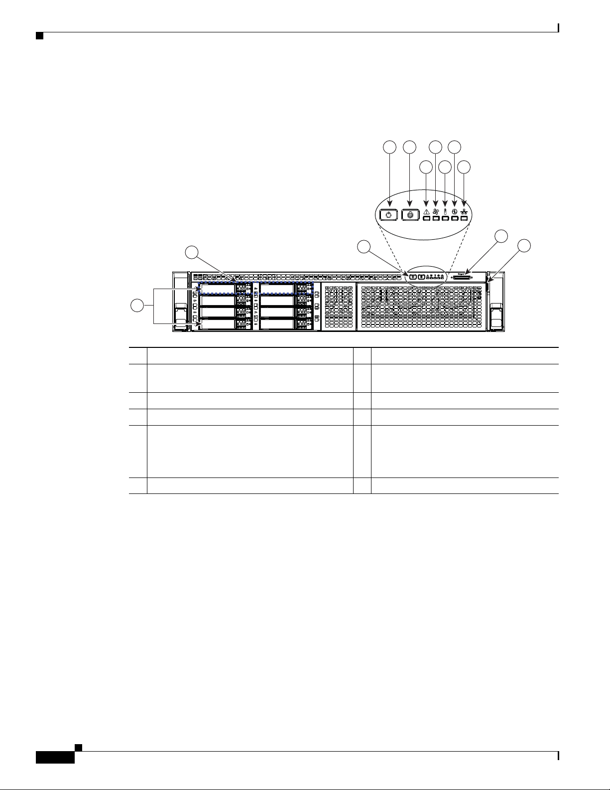
Figure 3-1 shows the front panel LEDs. Table 3-1 defines the LED states.
The small form factor (SFF) drives, 24-drive version and the SFF drives, 16-drive version are shown.
Chapter 3 Maintaining the Server
Figure 3-1 Front Panel LEDs
1 2
3
4
HDD01
HDD03
HDD04
HDD05
5
HDD02
HDD06
HDD07
HDD08
HDD09
HDD12
HDD14
HDD15
HDD16
HDD18
HDD19
HDD20
HDD22
HDD23
HDD10
HDD11
HDD13
HDD17
HDD21
HDD24
6
7
8
9
3 4 6 8
975
21
HDD01
HDD03
HDD05
HDD07
HDD02
HDD04
HDD06
HDD08
HDD09
HDD11
HDD13
HDD15
HDD10
HDD12
HDD14
HDD16
352950
3-2
1 Hard drive fault LED (on each drive tray)
Note: NVMe PCIe SSDs drive tray LEDs
have slightly different behavior . See Table 3-1
for the LED states.
2 Hard drive activity LED (on each drive tray) 7 Temperature status LED
3 Power button/power status LED 8 Power supply status LED
4 Unit Identification button/LED 9 Network link activity LED
5 System status LED
Cisco UCS C240 M4 Server Installation and Service Guide
6 Fan status LED
OL-32474-01
Page 45

Chapter 3 Maintaining the Server
Table 3-1 Front Panel LEDs, Definitions of States
LED Name State
1
SAS
Hard drive fault
Note: If your controller is a Cisco
UCS RAID SAS 9300-8i or
9300-8e HBA, see Cisco UCS
SAS 9300-8e HBA
• Off—The hard drive is operating properly.
• Amber—Drive fault detected.
• Amber, blinking—The device is rebuilding.
• Amber, blinking with one-second interval—Drive locate function activated.
Considerations, page C-4 for
differing LED behavior.
2
Hard drive activity
• Off—There is no hard drive in the hard drive tray (no access, no fault).
Status LEDs and Buttons
SAS
1
PCIe
2
PCIe
NVMe PCIe SSD status
(SFF, 8-drives version only)
NVMe PCIe SSD activity
(SFF, 8-drives version only)
3 Power button/LED
4 Unit Identification
• Green—The hard drive is ready.
• Green, blinking—The hard drive is reading or writing data.
• Off—The drive is not in use and can be safely removed.
• Green—The drive is in use and functioning properly.
• Green, blinking—the driver is initializing following insertion or the driver is
unloading following an eject command.
• Amber—The drive has failed.
• Amber, blinking—A drive Locate command has been issued in the software.
• Off—No drive activity.
• Green, blinking—There is drive activity.
• Off—There is no AC power to the server.
• Amber—The server is in standby power mode. Power is supplied only to the
Cisco IMC and some motherboard functions.
• Green—The server is in main power mode. Power is supplied to all server
components.
• Off—The unit identification function is not in use.
• Blue—The unit identification function is activated.
OL-32474-01
Cisco UCS C240 M4 Server Installation and Service Guide
3-3
Page 46

Chapter 3 Maintaining the Server
Status LEDs and Buttons
Table 3-1 Front Panel LEDs, Definitions of States (continued)
LED Name State
5 System status • Green—The server is running in a normal operating condition.
• Green, blinking—The server is p erform ing syst em ini tial ization and memory
check.
• Amber, steady—The server is in a degraded operational state. For example:
–
Power supply redundancy is lost.
–
CPUs are mismatched.
–
At least one CPU is faulty.
–
At least one DIMM is faulty.
–
At least one drive in a RAID configuration failed.
• Amber, blinking—The server is in a critical fault state. For example:
–
Boot failed.
–
Fatal CPU and/or bus error is detected.
–
Server is in an over-temperature condition.
6 Fan sta t u s
• Green—All fan modules are operating properly.
• Amber, steady—One or more fan modules breached the critical threshold.
7 Temperature status
8 Power supply status
9 Network link activity
• Amber, blinking—One or more fan modules breached the non-recoverable
threshold.
• Green—The server is operating at normal temperature.
• Amber, steady—One or more temperature sensors breached the critical
threshold.
• Amber, blinking—One or more temperature sensors breached the
non-recoverable threshold.
• Green—All power supplies are operating normally.
• Amber, steady—One or more power supplies are in a degraded operational
state.
• Amber, blinking—One or more power supplies are in a critical fault state.
• Off—The Ethernet link is idle.
• Green—One or more Ethernet LOM ports are link-active, but there is no
activity.
• Green, blinking—One or more Ethernet LOM ports are link-active, with
activity.
3-4
Cisco UCS C240 M4 Server Installation and Service Guide
OL-32474-01
Page 47

Chapter 3 Maintaining the Server
Rear Panel LEDs and Buttons
Figure 3-2 shows the rear panel LEDs and buttons. Table 3-2 defines the LED states.
Figure 3-2 Rear Panel LEDs and Buttons
Status LEDs and Buttons
1
2
PCIe 03
PCIe 02
PCIe 01
mLOM
3 6 85
1 Power supply fault LED 5 1-Gb Ethernet dedicated management link
2 Power supply AC status LED 6 1-Gb Ethernet link speed LED
3 Optional mLOM card LEDs
(not shown, see Table 3-2)
4 1-Gb Ethernet dedicated management link
speed LED
Table 3-2 Rear Panel LEDs, Definitions of States
LED Name State
1 Power supply fault
This is a summary; for advanced
power supply LED information,
see Table 3-3.
• Off—The power supply is operating normally.
• Amber, blinking—An event warning threshold has been reached, but the power
supply continues to operate.
• Amber, solid—A critical fault threshold has been reached, causing the power
supply to shut down (for example, a fan failure or an over-temperature
condition).
2 Power supply status
AC power supplies:
PCIe 06
PCIe 05
PCIe 04
4
7
PSU 02
PSU 01
352951
status LED
7 1-Gb Ethernet link status LED
8 Un it Identification button/LED
This is a summary; for advanced
power supply LED information,
see Table 3-3.
OL-32474-01
• Off—There is no AC power to the power supply.
• Green, blinking—AC power OK; DC output not enabled.
• Green, solid—AC power OK; DC outputs OK.
DC power supplies:
• Off—There is no DC power to the power supply.
• Green, blinking—DC power OK; DC output not enabled.
• Green, solid—DC power OK; DC outputs OK.
Cisco UCS C240 M4 Server Installation and Service Guide
3-5
Page 48

Status LEDs and Buttons
Table 3-2 Rear P anel LEDs, Definitions of States (continued)
LED Name State
3 Optional mLOM 10-Gb SFP+
(there is a single status LED)
3 Optional mLOM 10-Gb BASE-T
link speed
3 Optional mLOM 10-Gb BASE-T
link status
4 1-Gb Ethernet dedica ted
management link speed
5 1-Gb Ethernet dedica ted
management link status
6 1-Gb Ethernet link speed
• Off—No link is present.
• Green, steady—Link is active.
• Green, blinking—Traffic is present on the active link.
• Off—Link speed is 10 Mbps.
• Amber—Link speed is 100 Mbps/1 Gbps.
• Green—Link speed is 10 Gbps.
• Off—No link is present.
• Green—Link is active.
• Green, blinking—Traffic is present on the active link.
• Off—Link speed is 10 Mbps.
• Amber—Link speed is 100 Mbps.
• Green—Link speed is 1 Gbps.
• Off—No Link is present.
• Green—Link is active.
• Green, blinking—Traffic is present on the active link.
• Off—Link speed is 10 Mbps.
Chapter 3 Maintaining the Server
7 1-Gb Ethernet link status
8 Unit Identification
• Amber—Link speed is 100 Mbps.
• Green—Link speed is 1 Gbps.
• Off—No link is present.
• Green—Link is active.
• Green, blinking—Traffic is present on the active link.
• Off—The unit identification function is not in use.
• Blue—The unit identification function is activated.
3-6
Cisco UCS C240 M4 Server Installation and Service Guide
OL-32474-01
Page 49

Chapter 3 Maintaining the Server
In Table 3-3, read the status and fault LED states together in each row to determine the event that cause
this combination.
Table 3-3 Rear Power Supply LED States
Green PSU Status LED State A mber PSU Fault LED State Event
• Solid on • Off 12V main on (main power mode)
• Blinking • Off 12Vmain off (standby power mode)
• Off • Off No AC power input (all PSUs present)
• Off • On No AC power input (redundant supply active)
• Blinking • Solid on 12V over-voltage protection (OVP)
• Blinking • Solid on 12V under-voltage protection (UVP)
• Blinking • Solid on 12V over-current protection (OCP)
• Blinking • Solid on 12V short-circuit protection (SCP)
• Solid on • Solid on PSU fan fault/Lock (before OTP)
• Blinking • Solid on PSU fan fault/Lock (after OTP)
• Blinking • Solid on Over-temperature protection (OTP)
• Solid on • Blinking OTP warning
• Solid on • Blinking OCP warning
• Blinking • Off 12V main off (CR slave PSU is in sleep mode)
Status LEDs and Buttons
OL-32474-01
Cisco UCS C240 M4 Server Installation and Service Guide
3-7
Page 50

Status LEDs and Buttons
352952
FAN 0 6
1
2
3
FAN 05
FAN 04
FAN 0 3
FAN 02
FAN 01
CPU 1
CPU 2
SD1
SD2
Riser 2
Riser 1
4 65
Internal Diagnostic LEDs
The server is equipped with a supercap voltage source that can activate internal component fault LEDs
up to 30 minutes after AC power is removed. The serv er has internal fault LEDs for CPUs, DIMMs, fan
modules, SD cards, the RTC battery, and the mLOM ca rd.
To use these LEDs to identify a failed component, press the front or rear Unit Identification button (see
Figure 3-1 or Figure 3-2) with AC power removed. An LED lights amber to in dicate a faulty componen t.
See Figure 3-3 for the locations of these internal LEDs.
Figure 3-3 Internal Diagnostic LED Locations
Chapter 3 Maintaining the Server
3-8
1 Fan module fault LEDs (one on each fan
module)
2 DIMM fault LEDs (one directly in front of
each DIMM socket on the motherboard)
3 CP U fault LEDs 6 mLO M card faul t LED (un der PCIe riser 1)
Table 3-4 Internal Diagnostic LEDs, Definition of States
LED Name State
Internal diagnostic LEDs (all)
Cisco UCS C240 M4 Server Installation and Service Guide
4 SD card fault LEDs
5 RTC battery fault LED (under PCIe riser 1)
• Off—Component is functioning normally.
• Amber—Component has a fault.
OL-32474-01
Page 51

Chapter 3 Maintaining the Server
Preparing for Server Component Installation
This section describes how to prepare for component installation, and it includes the following topics:
• Required Equipment, page 3-9
• Shutting Down and Powering Off the Server, page 3-9
• Removing and Replacing the Server Top Cover, page 3-10
• Serial Number Location, page 3-12
• Hot-Swap or Hot-Plug Replacement, page 3-12
Required Equipment
The following equipment is used to perform the procedures in this chapter:
• Number 2 Phillips-head screwdriver
• Electrostatic discharge (ESD) strap or other grounding equipment such as a grounded mat
Preparing for Server Component Installation
Shutting Down and Powering Off the Server
The server can run in two power modes:
• Main power mode—Power is supplied to all server components and any operating system on your
drives can run.
• Standby power mode—Power is supplied only to the service processor and the cooling fans and it
is safe to power off the server from this mode.
You can invoke a graceful shutdown or a hard shutdown by using either of the following methods:
• Use the Cisco IMC management interface.
• Use the Power button on the server front panel. To use the Power button, follow these steps:
Step 1 Check the color of the Power Status LED (see the “Front Panel LEDs” section on page 3-2).
• Green—The server is in main power mode and must be shut down before it can be safely powered
off. Go to Step 2.
• Amber—The server is already in standby mode and can be safely powered off. Go to Step 3.
Step 2 Invoke either a graceful shutdown or a hard shutdown:
Caution To avoid data loss or damage to your operating system, you should always invoke a graceful shutdown
of the operating system.
OL-32474-01
• Graceful shutdown—Press and release the Power button. The operating system performs a graceful
shutdown and the server goes to standby mode, which is indicated by an amber Power Status LED.
• Emergency shutdown—Press and hold the Power button for 4 seconds to force the main power off
and immediately enter standby mode.
Step 3 Disconnect the power cords from the power supplies in your server to completely power off the server.
Cisco UCS C240 M4 Server Installation and Service Guide
3-9
Page 52

Preparing for Server Component Installation
Removing and Replacing the Server Top Cover
Step 1 Remove t h e to p c over ( s ee Figure 3-4).
a. If the cover latch is locked, use a screwdriver to turn the lock 90-degrees counterclockwise to unlo ck
it. See Figure 3-4.
b. Lift on the end of the latch that has the green finger grip. The cover is pushed back to the open
position as you lift the latch.
c. Lift the top cover straight up from the server and set it aside.
Step 2 Replace the top cover:
Note The latch must be in the fully open position when you set the cover back in place, which allows
the opening in the latch to sit over a peg that is on the fan tray.
a. With the latch in the fully open position, place the cover on top of the server about one-half inch
(1.27 cm) behind the lip of the front cover panel. The opening in the latch should fit over the peg
that sticks up from the fan tray.
b. Press the cover latch down to the closed posi tion. The co ver is pushed forwar d to the closed posit ion
as you push down the latch.
c. If desired, lock the latch by using a screwdriver to turn the lock 90-degrees clockwise.
Chapter 3 Maintaining the Server
3-10
Cisco UCS C240 M4 Server Installation and Service Guide
OL-32474-01
Page 53

Chapter 3 Maintaining the Server
352953
1 2
3
Figure 3-4 Removing the Top Cover
Preparing for Server Component Installation
1 Front cover panel 3 Locking cover latch
2 Top cover
OL-32474-01
Cisco UCS C240 M4 Server Installation and Service Guide
3-11
Page 54

Preparing for Server Component Installation
Serial Number Location
The serial number (SN) for the server is printed on a label on the top of the server, near the front.
Hot-Swap or Hot-Plug Replacement
Some components can be removed and replaced without powering off and remo ving AC power from the
server.
• Hot-swap replacement—You do not have to precondition or shut down the component in the
software before you remove it for the following components:
–
SAS/SATA hard drives or SSDs
–
Cooling fan modules
–
Power supplies (when 1+1 redundant)
• Hot-plug replacement—You must take the component offline before removing it for the following
component:
–
NVMe PCIe SSDs
Chapter 3 Maintaining the Server
3-12
Cisco UCS C240 M4 Server Installation and Service Guide
OL-32474-01
Page 55

Chapter 3 Maintaining the Server
Installing or Replacing Server Components
Installing or Replacing Server Components
Warning
Blank faceplates and cover panels serve three important functions: they prevent exposure to
hazardous voltages and currents inside the chassis; they contain electromagnetic interference (EMI)
that might disrupt other equipment; and they direct the flow of cooling air through the chassis. Do not
operate the system unless all cards, faceplates, front covers, and rear covers are in place.
Statement 1029
Caution When handling server components, wear an ESD strap to avoid damage.
Tip You can press the Unit Identification button on the front panel or rear panel to turn on a flashing Unit
Identification LED on the front and rear panels of the serv er . This button allo ws you to locate the specific
server that you are servicing when you go to the opposite side of the rack. You can also activate these
LEDs remotely by using the Cisco IMC interface. See the “Status LEDs and Buttons” section on
page 3-2 for locations of these LEDs.
This section describes how to install and replace serv er components, and it includes the follo wing topics:
• Replaceable Component Locations, page 3-14
• Replacing SAS/SATA Hard Drives or Solid State Drives, page 3-15
• Replacing NVMe PCIe Solid State Drives, page 3-19
• Replacing Fan Modules, page 3-23
• Replacing DIMMs, page 3-25
• Replacing CPUs and Heatsinks, page 3-29
• Replacing a SATA Interposer Board, page 3-34
• Replacing a Cisco Modular RAID Controller Card, page 3-36
• Replacing a Modular RAID Controller Transportable Memory Module (TMM), page 3-38
• Replacing the Supercap Power Module (RAID Backup Battery), page 3-40
• Replacing a Software RAID 5 Key Module, page 3-42
• Replacing the Motherboard RTC Battery, page 3-44
• Replacing an Internal SD Card, page 3-45
• Enabling or Disabling the Internal USB Port, page 3-46
• Replacing a PCIe Riser, page 3-47
• Replacing a PCIe Card, page 3-49
• Installing an NVIDIA GPU Card, page 3-57
• Replacing Internal SATA Boot Drives, page 3-57
• Installing a Trusted Platform Module (TPM), page 3-59
• Replacing Power Supplies, page 3-64
• Replacing an mLOM Card, page 3-69
OL-32474-01
Cisco UCS C240 M4 Server Installation and Service Guide
3-13
Page 56

Installing or Replacing Server Components
Chapter 3 Maintaining the Server
Replaceable Component Locations
Figure 3-5 shows the locations of the components that are supported as field-replaceable. The view
shown is from the top down, with the top covers and air baffle removed.
Figure 3-5 Replaceable Component Locations
1
2
FAN 06
FAN 0 5
FAN 04
FAN 03
FAN 02
FAN 01
3
4
CPU 2
CPU 1
5
SD2
6
SD1
7
8
9
Riser 2
Riser 1
10
11
12
13
1 Drives bays. All drive bays support SAS/SATA drives.
17
18
10 PCIe riser 2 (PCIe slots 4, 5, 6)
1516
14
SFF, 8-, 16-, and 24-drive versions only: Drive bays 1
and 2 support SAS/SATA dri v es and NVMe PCIe SSDs.
NVMe drives require a PCIe interposer board for PCIe
bus connection (see item 6).
2 Fan modules (six, hot-swappable) 11 PCIe riser 1 (PCIe slots 1, 2, 3*)
*Slot 3 not present in all versions. See Replacing a PCIe
Card, page 3-49 for riser options and slot specifications.
3 DIMM sockets on motherboard (up to 24 DIMMs) 12 SA TA boot drives (tw o sockets a v ailable only on PCIe riser
1 option 1C)
4 CPUs and heatsinks (two) 13 mLOM card socket on motherboard under
PCIe riser 1
5 Cisco SD card slots on motherboard (two) 14 Socket for embedded RAID interposer board
6 PCIe interposer board socket 15 Cisco modular RAID controller PCIe slot
(dedicated slot and bracket)
7 USB 3.0 slot on motherboard 16 RTC battery on motherboard
8 Power supplies (hot-swappable, accessed through rear
17 Embedded RAID header for RAID 5 key
panel)
9 Trusted platform module (TPM) socket on motherboard,
under PCIe riser 2
18 Supercap power module (RAID backup) mountin g location
on air baffle (not shown)
352948
3-14
The Technical Specifications Sheets for all versions of this server, which include supported component
part numbers, are at Cisco UCS Servers Technical Specifications Sheets.
Cisco UCS C240 M4 Server Installation and Service Guide
OL-32474-01
Page 57

Chapter 3 Maintaining the Server
352954
HDD01
HDD02
HDD03
HDD04
HDD05
HDD06
HDD07
HDD08
HDD09
HDD10
HDD11
HDD12
HDD13
HDD14
HDD15
HDD16
HDD17
HDD18
HDD19
HDD20
HDD21
HDD22
HDD23
HDD24
HDD01
HDD03
HDD05
HDD07
HDD02
HDD04
HDD06
HDD08
HDD09
HDD11
HDD13
HDD15
HDD10
HDD12
HDD14
HDD16
352955
Replacing SAS/SATA Hard Drives or Solid State Drives
This section includes the following information:
• SAS/SATA Drive Population Guidelines, page 3-15
• Replacing SAS/SATA Drives, page 3-18
SAS/SATA Drive Population Guidelines
The server is orderable in four different versions, each with one of four different front panel/backplane
configurations:
• Cisco UCS C240 M4—Small form-factor (SFF) drives with 24-drive backplane and expander.
This version holds up to 24 2.5-inch SAS/ SAT A hard dri v es or solid state driv es (SSDs). SAS/SAT A
drives are hot-swappable.
• Cisco UCS C240 M4—SFF drives, with 16-drive backplane and integrated expander.
This version holds up to 16 2.5-inch SAS/SATA hard drives or soli d state drives. SAS/SATA driv es
are hot-swappable.
• Cisco UCS C240 M4—SFF drives, with 8-drive direct-connect backplane and no expander.
This version holds up to 8 2.5-inch SAS/SATA hard drives or solid state drives. SAS/SATA drives
are hot-swappable.
Installing or Replacing Server Components
• Cisco UCS C240 M4—Large form-factor (LFF) drives, with 12-drive backplane and integrated
expander. This version holds up to 12 3.5-inch SAS/SATA hard drives. SAS/SATA drives are
hot-swappable.
Note You cannot change the backplane type after-factory. To change a front panel/backplane configurati on, a
chassis replacement is required.
The drive-bay numbering for all server versions is shown in Figure 3-6 through Figure 3-9.
Figure 3-6 Drive Numbering, SFF Drives, 24-Drive Version
Figure 3-7 Drive Numbering, SFF Drives, 16-Drive Version
OL-32474-01
Cisco UCS C240 M4 Server Installation and Service Guide
3-15
Page 58

Installing or Replacing Server Components
352956
HDD 01 HDD 02
HDD 04
HDD 06
HDD 08
HDD 03
HDD 05
HDD 07
Chapter 3 Maintaining the Server
Figure 3-8 Drive Numbering, SFF Drives, 8-Drive Version
Figure 3-9 Drive Numbering, LFF Drives, 12-Drive Version
HDD 01
HDD 05
HDD 09
HDD 02
HDD 06
HDD 10
HDD 03
HDD 07
HDD 11
HDD 04
HDD 08
HDD 12
352957
Observe these drive population guidelines for optimal performance:
• When populating drives, add drives in the lowest numbered bays first.
• Keep an empty drive blanking tray in any unused bays to ensure optimal airflow and cooling.
• You can mix hard drives and solid state drives in the same server. However, you cannot configure a
logical volume (virtual drive) that contains a mix of hard drives and SSDs. That is, when you create
a logical volume, it must contain all hard drives or all SSDs.
4K Sector Format Drives Considerations
• You must boot 4K sector format drives in UEFI mode, not legacy mode. See Setting Up Booting in
UEFI Mode in the BIOS Setup Utility, page 3-17 or Setting Up Boot ing i n UEFI Mod e in the Ci sco
IMC GUI, page 3-17.
• Do not configure 4K sector format and 512-byte sector format drives as part of the same RAID
volume.
• Operating system support on 4K sector drives is as follows: Windows: Win2012 and Win2012R2;
Linux: RHEL 6.5, 6.6, 6.7, 7.0, 7.2; SLES 11 SP3, and SLES 12. ESXi/Vmware is not supported.
Cisco UCS C240 M4 Server Installation and Service Guide
3-16
OL-32474-01
Page 59

Chapter 3 Maintaining the Server
Setting Up Booting in UEFI Mode in the BIOS Setup Utility
Step 1 Enter the BIOS setup utility by pressing the F2 key when prompted during bootup.
Step 2 Go to the Boot Options tab.
Step 3 Set UEFI Boot Options to Enabled.
Step 4 Under Boot Option Priorities, set your OS installation media (such as a virtual DVD) as your
Boot Option #1.
Step 5 Go to the Advanced tab.
Step 6 Select LOM and PCIe Slot Configuration.
Step 7 Set the PCIe Slot ID: HBA Option ROM to UEFI Only.
Step 8 Press F10 to save changes and exit the BIOS setup utility. Allow the server to reboot.
Step 9 After the OS installs, verify the installation:
a. Enter the BIOS setup utility by pressing the F2 key when prompted during bootup.
b. Go to the Boot Options tab.
c. Under Boot Option Priorities, verify that the OS you installed is listed as your Boot Option #1.
Installing or Replacing Server Components
Setting Up Booting in UEFI Mode in the Cisco IMC GUI
Step 1 Use a web browser and the IP address of the server to log into the Cisco IMC GUI management interface.
Step 2 Navigate to Server > BIOS.
Step 3 Under Actions, click Configure BIOS.
Step 4 In the Configure BIOS Parameters dialog, select the Advanced tab.
Step 5 Go to the LOM and PCIe Slot Configuration section.
Step 6 Set the PCIe Slot: HBA Option ROM to UEFI Only.
Step 7 Click Save Changes. The dialog closes.
Step 8 Under BIOS Properties, set Configured Boot Order to UEFI.
Step 9 Under Actions, click Configure Boot Order.
Step 10 In the Configure Boot Order dialog, click Add Local HDD.
Step 11 In the Add Local HDD dialog, enter the information for the 4K sector format drive and make it first in
the boot order.
Step 12 Save changes and reboot the server. The changes you made will be visible after the system reboots.
OL-32474-01
Cisco UCS C240 M4 Server Installation and Service Guide
3-17
Page 60

Installing or Replacing Server Components
Chapter 3 Maintaining the Server
Replacing SAS/SATA Drives
Tip You do not have to shut down or power off the server to replace SAS/SATA hard drives or solid state
drives (SSDs) because they are hot-swappable. To replace an NVMe PCIe SSD drive, which must be shut
down before removal, see Replacing NVMe PCIe Solid State Drives, page 3-19.
Step 1 Remove the drive that you are replacing or remove a blank drive tray from an empty bay:
a. Press the release button on the face of the drive tray. See Figure 3-10.
b. Grasp and open the ejector lever and then pull the drive tray out of the slot.
c. If you are replacing an existing drive, remove the four drive-tray screws that secure the drive to the
tray and then lift the drive out of the tray.
Step 2 Install a new drive:
a. Place a new drive in the empty drive tray and replace the four drive-tray screws.
b. With the ejector lever on the drive tray open, insert the drive tray into the empty drive bay.
c. Push the tray into the slot until it touches the backplane, and then close the ejector lever to lock the
drive in place.
Figure 3-10 Replacing Drives
HDD02
21
HDD03
HDD04
HDD05
HDD06
HDD07
3
HDD08
HDD09
HDD12
HDD14
HDD15
HDD16
HDD18
HDD19
HDD20
HDD22
HDD23
HDD10
HDD11
HDD13
HDD17
HDD21
HDD24
3
3
3
1 Release button 3 Drive tray securing screws (four)
2 Ejec tor lever –
352958
3-18
Cisco UCS C240 M4 Server Installation and Service Guide
OL-32474-01
Page 61

Chapter 3 Maintaining the Server
Replacing NVMe PCIe Solid State Drives
• NVMe PCIe SSD Population Guidelines, page 3-19
• NVME PCIe SSD Requirements and Restrictions, page 3-19
• Replacing an NVMe PCIe SSD, page 3-19
• Installing a PCIe Interposer Board, page 3-20
NVMe PCIe SSD Population Guidelines
The SFF versions of the server (8-, 16-, and 24-drive) support up to two NVMe PCIe solid state drives
(SSDs) in drive bays 1 and 2 only.
NVME PCIe SSD Requirements and Restrictions
Observe these requirements for NVMe PCIe SSDs:
• The SFF 8-drives, 16-drives, or 24-drives version of the server.
Installing or Replacing Server Components
• The PCIe interposer board with bundled cables for your server version:
–
SFF 8- or 16-drives server: UCSC-IP-SSD-240M4
–
SFF 24-drives server: UCSC-IP-SSD-240M4B
• The server must have tw o CPUs. The PCIe interposer board is not a v ai lable in a single-CPU system.
Observe these restrictions for NVMe PCIe SSDs:
• You cannot boot from an NVMe PCIe SSD.
• You cannot control an NVMe PCIe SSD with a SAS RAID controller because they communicate
with the server via the PCIe bus.
Caution NVMe PCIe SSDs are hot-pluggable, which means that you must shut down the drive before removal,
but you do not have to fully power off the server. To replace a SAS/SATA drive, see Replacing
SAS/SATA Drives, page 3-18.
Replacing an NVMe PCIe SSD
For information about drive tray LEDs, see Front Panel LEDs, page 3-2.
Step 1 Remove an existing NVMe PCIe SSD:
a. Shut down the NVMe PCIe SSD. Use your operating system interface to shut down the drive, and
then observe the drive-tray LED:
–
Green—The drive is in use and functioning properly. Do not remove.
OL-32474-01
–
Green, blinking—the driver is unloading following a shutdown command. Do not remove.
–
Off—The drive is not in use and can be safely removed.
b. Press the release button on the face of the drive tray. See Figure 3-10.
c. Grasp and open the ejector lever and then pull the drive tray out of the slot.
Cisco UCS C240 M4 Server Installation and Service Guide
3-19
Page 62

Installing or Replacing Server Components
d. If you are replacing an existing SSD, remove the four drive tray screws that secure the SSD to the
tray and then lift the SSD out o f the tray.
Note If this is the first time that NVMe PCIe SSDs are being installed in the server, you must install a PCIe
interposer board and connect its cables before installing the drive. See Installing a PCIe Interposer
Board, page 3-20.
Step 2 Install a new NVMe PCIe SSD:
a. Place a new SSD in the empty drive tray and replace the four drive tray screws.
b. With the ejector lever on the drive tray open, insert the drive tray into the empty drive bay.
c. Push the tray into the slot until it touches the backplane, and then close the ejector lever to lock the
drive in place.
Step 3 Observe the drive-tray LED and wait until it returns to solid green before accessing the drive:
• Off—The drive is not in use.
• Green, blinking—the driver is initializing following hot-plug insertion.
• Green—The drive is in use and functioning properly.
Chapter 3 Maintaining the Server
Installing a PCIe Interposer Board
A PCIe interposer board is used to pro vide communication with the PCIe b us from the NVMe PCIe SSDs
in the front panel bays. Use the correct interposer board, with bundled cables, for your version of the
server:
• SFF 8-drive or 16-drive: UCSC-IP-SSD-240M4
• SFF 24-drive: UCSC-IP-SSD-240M4B
3-20
Cisco UCS C240 M4 Server Installation and Service Guide
OL-32474-01
Page 63

Chapter 3 Maintaining the Server
Figure 3-11 PCIe Interposer Board
Installing or Replacing Server Components
1 Connector for PCIe cable 3 Securing clip on interposer board
2 Motherboard socket
Step 1 Power off the server as described in Shutting Down and Powering Off the Server, page 3-9.
Step 2 Slide the server out the front of the rack far enou gh so that you can remov e the top co ver. You migh t hav e
to detach cables from the rear panel to provide clearance.
Caution If you cannot safely view and access the component, remove the server from the rack.
Step 3 Remove t h e to p c over a s d e s c ri b ed i n Removing and Replacing the Server Top Cover, page 3-10.
Step 4 Install a new PCIe interposer board:
a. Locate the PCIe interposer board socket on the motherboard (see Figure 3-12).
b. Pinch the securing clip on the board while you insert the board to the socket as shown in Figure 3 -11.
c. Carefully push down to seat the board, then release the securing clip.
Step 5 Connect the two cables that come with the interposer board:
a. Connect the double-connector end of the cable to the interposer board (see Figure 3-11).
b. Route the cables to the front of the server using the recommended path through the chassis cable
guides as shown in Figure 3-12.
c. Connect the two ends of the cable to the PCIe connectors on the drive backplane.
Connect the cable labeled Port A to the Port A connector; connect the cable labeled Port B to the
Port B connector.
OL-32474-01
Step 6 Replace the top cover.
Step 7 Replace the server in the rack, replace cables, and then power on the serv er by pressing the Power button.
Cisco UCS C240 M4 Server Installation and Service Guide
3-21
Page 64

Installing or Replacing Server Components
Figure 3-12 PCIe Interposer Board Cabling
Chapter 3 Maintaining the Server
1 PCIe interposer board socket on motherboard
3-22
Cisco UCS C240 M4 Server Installation and Service Guide
OL-32474-01
Page 65

Chapter 3 Maintaining the Server
Replacing Fan Modules
The six hot-swappable fan modules in the server ar e numbered as follows when you are facing the fron t
of the server.
Figure 3-13 Fan Module Numbering
FAN 6 FAN 5 FAN 4 FAN 3 FAN 2 FAN 1
Tip A fault LED is on the top of each fan module that lights amber if the fan module fails. To operate these
LEDs from the SuperCap power source, remove AC power cords and then press the Unit Identification
button. S e e a l s o Internal Diagnostic LEDs, page 3-8.
Caution You do not have to shut down or power off the server to replace fan modules because they are hot-
swappable. Howe ver , to maintain proper cooling, do not oper ate the server for more than one min ute with
any fan module removed.
Installing or Replacing Server Components
Step 1 Slide the server out the front of the rack far enou gh so that you can remov e the top co ver. You migh t hav e
to detach cables from the rear panel to provide clearance.
Caution If you cannot safely view and access the component, remove the server from the rack.
Step 2 Remove t h e to p c over a s d e s c ri b ed i n Removing and Replacing the Server Top Cover, page 3-10.
Step 3 Identify a faulty fan module by looking for a fan fault LED that is lit amber (see Figure 3-14).
Step 4 Remove a fan module that you are replacing (see Figure 3-14):
a. Grasp the top of the fan and pinch the green plastic latch toward the center.
b. Lift straight up to remove the fan module from the server.
Step 5 Install a new fan module:
a. Set the new fan module in place, aligning the connector on the bottom of the fan module with the
connector on the motherboard.
Note The arrow label on the top of the fan module, which indicates the direction of airflow, should
point toward the rear of the server.
b. Press down gently on the fan module until the latch clicks and locks in place.
Step 6 Replace the top cover.
Step 7 Replace the server in the rack.
OL-32474-01
Cisco UCS C240 M4 Server Installation and Service Guide
3-23
Page 66

Installing or Replacing Server Components
Figure 3-14 Fan Modules Latch and Fault LED
1 2
Chapter 3 Maintaining the Server
SD2
SD1
FAN 05
FAN 04
FAN 0 3
FAN 02
FAN 01
CPU 2
Riser 2
CPU 1
Riser 1
352959
1 Finger latch (on each fan module) 2 Fan module fault LED (on each fan module)
3-24
Cisco UCS C240 M4 Server Installation and Service Guide
OL-32474-01
Page 67

Chapter 3 Maintaining the Server
Replacing DIMMs
This section includes the following topics:
• Memory Performance Guidelines and Population Rules, page 3-25
• DIMM Replacement Procedure, page 3-28
Caution DIMMs and their sockets are fragile and must be handled with care to avoid damage during installation.
Caution Cisco does not support third-party DIMMs. Using non-Cisco DIMMs in the server might result in system
problems or damage to the motherboard.
Note To ensure the best server performance, it is important that you are familiar with memory performance
guidelines and population rules before you install or replace the memory.
Installing or Replacing Server Components
Memory Performance Guidelines and Population Rules
This section describes the type of memory that the server requires and its effect on performance. The
section includes the following topics:
• DIMM Socket Numbering, page 3-26
• DIMM Population Rules, page 3-26
• Memory Mirroring and RAS, page 3-27
• Lockstep Channel Mode, page 3 -27
OL-32474-01
Cisco UCS C240 M4 Server Installation and Service Guide
3-25
Page 68

Installing or Replacing Server Components
DIMM Socket Numbering
Figure 3-15 shows the numbering of the DIMM sockets and CPUs.
Chapter 3 Maintaining the Server
DIMM Population Rules
Figure 3-15 CPUs and DIMM Socket Numbering on Motherboard
CPU 1
B3
G1
G2
G3H1H2
H3
CPU 2
F3F2F1
E3
E2
E1
C1C2C3
D1D2D3
Front of Server
Observe the following guidelines when installing or replacing DIMMs:
• Each CPU supports four memory channels.
–
CPU1 supports channels A, B, C, and D.
–
CPU2 supports channels E, F, G, and H.
• Each channel has three DIMM sockets (for example, channel A = slots A1, A2, and A3).
–
A channel can operate with one, two, or three DIMMs installed.
–
If a channel has only one DIMM, populate slot 1 first (the blue slot).
• When both CPUs are installed, populate the DIMM sockets of each CPU identically.
B2
B1
A3
A2
A1
352815
–
Fill blue #1 slots in the channels first: A1, E1, B1, F1, C1, G1, D1, H1
–
Fill black #2 slots in the channels second: A2, E2, B2, F2, C2, G2, D2, H2
–
Fill white #3 slots in the channels third: A3, E3, B3, F3, C3, G3, D3, H3
• Any DIMM installed in a DIMM socket for which the CPU is absent is not recognized. In a
single-CPU configuration, populate the channels for CPU1 only (A, B, C, D).
• Memory mirroring reduces the amount of memory available by 50 percent because only one of the
two populated channels provides data. When memory mirroring is enabled, you mu st install DIMMs
in sets of 4, 6, 8, or 12 as described in Memory Mirroring and RAS, page 3-27.
• NVIDIA GPUs can support only less than 1 TB of memory in the server. Therefore, do not install
more than fourteen 64-GB DIMMs when using an NVIDIA GPU card in this server.
• Observe the DIMM mixing rules shown in Table 3-5.
3-26
Cisco UCS C240 M4 Server Installation and Service Guide
OL-32474-01
Page 69

Chapter 3 Maintaining the Server
Installing or Replacing Server Components
Table 3-5 DIMM Mixing Rules for C240 M4 Servers
DIMM Parameter DIMMs in the Same Channel DIMMs in the Same Bank
DIMM Capacity:
RDIMM = 8 or 16 GB
LRDIMM = 32 or 64 GB
DIMM Speed:
2133 or 2400 MHz
DIMM Type:
RDIMMs or LRDIMMs
Memory Mirroring and RAS
The Intel E5-2600 CPUs within the server support memory mirroring only when an even number of
channels are populated with DIMMs. If one or three channels are populated with DIMMs, memory
mirroring is automatically disabled. Furthermore, if memory mirroring is used, DRAM size is reduced
by 50 percent for reasons of reliability.
For details on populating recommended memory mirroring conf igurations, see the specif ication sheet for
the server:
• Cisco UCS C240 M4 High Density Rack Server (Small Form-Factor Disk Drive Model)
• Cisco UCS C240 M4 High Density Rack Server (Large Form-Factor Disk Drive Model)
• You can mix different capacity
DIMMs in the same channel (for
example, A1, A2, A3).
Y ou can mix speeds, but DIMMs will run at
the speed of the slowest DIMMs/CPUs
installed in the channel.
You cannot mix DIMM types in a channel. You cannot mix DIMM types in a bank.
Specification Sheet
Specification Sheet
• You can mix different capacity DIMMs
in the same bank. However, for optimal
performance DIMMs in the same bank
(for example, A1, B1, C1, D1) should
have the same capacity.
You can mix speeds, but DIMMs will run at
the speed of the slowest DIMMs/CPUs
installed in the bank.
Lockstep Channel Mode
OL-32474-01
When you enable lockstep channel mode, each memory access is a 128-bit data access that spans four
channels.
Lockstep channel mode requires that all f our memory channels on a CPU must be populated identically
with regard to size and organization. DIMM socket populations within a channel (for example, A1, A2,
A3) do not have to be identical but the same DIMM slot location across all four channels must be
populated the same.
For example, DIMMs in sockets A1, B1, C1, and D1 must be identical. DIMMs in sockets A2, B2, C2,
and D2 must be identical. However, the A1-B1-C1-D1 DIMMs do not have to be identical with the
A2-B2-C2-D2 DIMMs.
Cisco UCS C240 M4 Server Installation and Service Guide
3-27
Page 70

Installing or Replacing Server Components
DIMM Replacement Procedure
This section includes the following topics:
• Identifying a Faulty DIMM, page 3-28
• Replacing DIMMs, page 3-28
Identifying a Faulty DIMM
Each DIMM socket has a corresponding DIMM fault LED, directly in front of the DIMM socket. See
Figure 3-3 for the locations of these LEDs. The LEDs light amber to indicate a faulty DIMM. To operate
these LEDs from the SuperCap power source, remove AC power cords and then press the Unit
Identification button.
Replacing DIMMs
Step 1 Power off the server as described in Shutting Down and Powering Off the Server, page 3-9.
Step 2 Slide the server out the front of the rack far enou gh so that you can remov e the top co ver. You migh t hav e
to detach cables from the rear panel to provide clearance.
Chapter 3 Maintaining the Server
Caution If you cannot safely view and access the component, remove the server from the rack.
Step 3 Remove t h e to p c over a s d e s c ri b ed i n Removing and Replacing the Server Top Cover, page 3-10.
Step 4 Remove the air baffle that sits over the DIMM sockets and set it aside.
Step 5 Identify the faulty DIMM by observing the DIMM socket fault LEDs on the motherboard (see
Figure 3-3).
Step 6 Remove the DIMMs that you are replacing. Open the ejector levers at both ends of the DIMM socket,
and then lift the DIMM out of the socket.
Step 7 Install a new DIMM:
Note Before installing DIMMs, see the population guidelines. See Memory Performance Guidelines
and Population Rules, page 3-25.
a. Align the new DIMM with the empty socket on the motherboard. Use the alignment key in the
DIMM socket to correctly orient the DIMM.
b. Push down evenly on the top corners of the DIMM until it is fully seated and the ejector levers on
both ends lock into place.
Step 8 Replace the air baffle.
Step 9 Replace the top cover.
Step 10 Replace the server in the rack, replace cables, and then power on the server by pressi ng the Power button.
3-28
Cisco UCS C240 M4 Server Installation and Service Guide
OL-32474-01
Page 71

Chapter 3 Maintaining the Server
Installing or Replacing Server Components
Replacing CPUs and Heatsinks
This section contains the following topics:
• Special Information For Upgrades to Intel Xeon v4 CPUs, page 3-29
• CPU Configuration Rules, page 3-29
• Replacing a CPU and Heatsink, page 3-30
• Additional CPU-Related Parts to Order with RMA Replacement Motherboards, page 3-33
Special Information For Upgrades to Intel Xeon v4 CPUs
Caution You must upgrade your server firmware to the required minimum level before you upgrade to Intel v4
CPUs. Older firmware versions cannot recognize the new CPUs and this results in a non-bootable server .
The minimum software and firmware versions required for the server to support Intel v4 CPUs are as
follows:
Table 3-6 Minimum Requirements For Intel Xeon v4 CPUs
Software or Firmware Minimum Version
Server CIMC 2.0(10)
Server BIOS 2.0(10)
Cisco UCS Manager
(UCSM-managed system only)
3.1(0)
Do one of the following actions:
• If your server’s firmware and/or Cisco UCS Manager software are already at the required levels
shown in Table 3-6, you can replace the CPU hardware by us ing the procedure in this section.
• If your server’ s fi rmware and/or Cisco UCS Manager softw are is earlier than the r equired le vels, use
the instructions in the Cisco UCS C-Series Servers Upgrade Guide for Intel Xeon v4 CPUs to
upgrade your software. After you upgrade the software, return to the procedure in this section as
directed to replace the CPU hardware.
CPU Configuration Rules
This server has two CPU sockets. Each CPU supports four DIMM channels (12 DIMM sockets). See
Figure 3-15.
• The server can operate with one CPU or with two identical CPUs installed.
• The minimum configuration is that the serv er must have at least CPU1 installed. Install CPU1 f irst,
and then CPU2.
• The following restrictions apply when using a single-CPU configuration:
–
–
–
The maximum number of DIMMs is 12 (only CPU1 channels A, B, C, and D).
PCIe riser 2, which contains PCIe slots 4, 5, and 6 is unavailable.
The PCIe SSD interposer board is unavailable.
OL-32474-01
Cisco UCS C240 M4 Server Installation and Service Guide
3-29
Page 72

Installing or Replacing Server Components
Replacing a CPU and Heatsink
Caution CPUs and their motherboard sockets are fragile and must be handled with care to avoid damaging pins
during installation. The CPUs must be installed with heatsinks and their thermal grease to ensure proper
cooling. Failure to install a CPU correctly might result in damage to the server.
Note This server uses the new independent loading mechanism (ILM) CPU sockets, so no Pick-and-Place
tools are required for CPU handling or installation. Always grasp the plastic frame on the CPU when
handling.
Step 1 Power off the server as described in Shutting Down and Powering Off the Server, page 3-9.
Step 2 Slide the server out the front of the rack far enou gh so that you can remov e the top co ver. You migh t hav e
to detach cables from the rear panel to provide clearance.
Chapter 3 Maintaining the Server
Caution If you cannot safely view and access the component, remove the server from the rack.
Step 3 Remove t h e to p c over a s d e s c ri b ed i n Removing and Replacing the Server Top Cover, page 3-10.
Step 4 Remove the plastic air baffle that sits over the CPUs.
Step 5 Remove the heatsink that you are replacing:
a. Use a Number 2 Phillips-head screwdriv er to loosen the four captive screws that secure the heatsink.
Note Alternate loosening each screw evenly to avoid damaging the heatsink or CPU.
b. Lift the heatsink off of the CPU.
Step 6 Open the CPU retaining mechanism:
a. Unclip the first retaining latch labeled with the icon, and then unclip the second retaining
latch labeled with the icon. See Figure 3-16.
b. Open the hinged CPU cover plate.
3-30
Cisco UCS C240 M4 Server Installation and Service Guide
OL-32474-01
Page 73

Chapter 3 Maintaining the Server
1
2
4
3
5
352941
Figure 3-16 CPU Socket
Installing or Replacing Server Components
1 CPU retaining latch 4 Hinged CPU seat
2 CPU retaining latch 5 Finger-grips on plastic CPU frame
3 Hinged CPU cover plate
Step 7
Remove any existing CPU:
a. With the latches and hinged CPU cover plate open, swing the CPU in its hinged seat up to the open
position, as shown in Figure 3-16.
b. Grasp the CPU by the finger-grips on its plastic frame an d l ift it up and out of the hinged CPU seat.
c. Set the CPU aside on an antistatic surface.
Step 8 Install a new CPU:
a. Grasp the new CPU by the finger-grips on its plastic frame and align the tab on the frame that is
labeled “ALIGN” with the hinged seat, as shown in Figure 3-17.
b. Insert the tab on the CPU frame into the seat until it stops and is held firmly.
The line below the word “ALIGN” should be level with the edge of the seat, as shown in Figure 3-17.
c. Swing the hinged seat with the CPU down until the CPU frame clicks in place and holds flat in the
socket.
d. Close the hinged CPU cover plate.
e. Clip down the CPU retaining latch with the icon, and then clip down th e CPU retaining latch
with the icon. See Figure 3-16.
Cisco UCS C240 M4 Server Installation and Service Guide
OL-32474-01
3-31
Page 74

Installing or Replacing Server Components
2
1
352942
Figure 3-17 CPU and Socket Alignment Features
Chapter 3 Maintaining the Server
1 SLS mechanism on socket 2 Tab on CPU frame (labeled ALIGN)
Step 9
Caution The heat sink must have new thermal grease on the heat sink-to-CPU surface to ensure proper cooling.
Install a heat sink:
If you are reusing a heat sink, you must remove the old thermal grease from the heatsink and the CPU
surface. If you are installing a new heat sink, skip to Step c.
a. Apply the cleaning solution, which is included with the heatsink cleaning kit (UCSX-HSCK=,
shipped with spare CPUs), to the old thermal grease on the heatsink and CPU and let it soak for a
least 15 seconds.
b. Wipe all of the old thermal grease off the old heat sink and CPU using the soft cloth that is included
with the heatsink cleaning kit. Be careful to not scratch the heat sink surface.
Note New heatsinks come with a pre-applied pad of thermal grease. If you are reusing a heatsink, you
must apply thermal grease from a syringe (UCS-CPU-GREASE3=).
c. Align the four heatsink captive screws with the motherboard standoffs, and then use a Number 2
Phillips-head screwdriver to tighten the captive screws evenly.
Note Alternate tightening each screw evenly to avoid damaging the heatsink or CPU.
3-32
Step 10 Replace the air baffle.
Step 11 Replace the top cover.
Step 12 Replace the server in the rack, replace cables, and then power on the server by pressi ng the Power button.
Cisco UCS C240 M4 Server Installation and Service Guide
OL-32474-01
Page 75

Chapter 3 Maintaining the Server
Installing or Replacing Server Components
Additional CPU-Related Parts to Order with RMA Replacement Motherboards
When a return material authorization (RMA) of the motherboard or CPU is done on a Cisco UCS
C-series server, additional parts might not be included with the CPU or motherboard spare bill of
materials (BOM). The TAC engineer might need to add the additional parts to the RMA to help ensure
a successful replacement.
Note This server uses the new independent loading mechanism (ILM) CPU sockets, so no Pick-and-Place
tools are required for CPU handling or installation. Always grasp the plastic frame on the CPU when
handling.
• Scenario 1—You are reusing the existing heatsinks:
–
Heat sink cleaning kit (UCSX-HSCK=)
–
Thermal grease kit for C240 M4 (UCS-CPU-GREASE3=)
• Scenario 2—You are replacing the existing heatsinks:
–
Heat sink (UCSC-HS-C240M4=)
–
Heat sink cleaning kit (UCSX-HSCK=)
A CPU heatsink cleaning kit is good for up to four CPU and heatsi nk cleanings. The cleaning kit con tains
two bottles of solution, one to clean the CPU an d heatsink of old ther mal interface materi al and the other
to prepare the surface of the heatsink.
New heatsink spares come with a pre-applied pad of thermal grease. It is important to clean the old
thermal grease off of the CPU prior to installing the heatsinks. Therefore, when you are ordering new
heatsinks, you must order the heatsink cleaning kit.
OL-32474-01
Cisco UCS C240 M4 Server Installation and Service Guide
3-33
Page 76

Installing or Replacing Server Components
Replacing a SATA Interposer Board
The server uses a SATA interposer board and cable to connect the embedded RAID (PCH SATA)
controller on the motherboard to the drive backplane. See Figure 3-18 for the socket location.
Note The SATA interposer board and embedded RAID can be used only with the SFF, 8-drive backplane
version of the server. It does not operate with an expander. You cannot use the embedded RAID
controller and a hardware RAID controller card at the same time.
See Embedded SATA RAID Controller, page C-10 for more information about using the embedded
RAID controller and options.
Step 1 Power off the server as described in the Shutting Down and Powering Off the Server, page 3-9.
Step 2 Slide the server out the front of the rack far enou gh so that you can remov e the top co ver. You migh t hav e
to detach cables from the rear panel to provide clearance.
Caution If you cannot safely view and access the component, remove the server from the rack.
Chapter 3 Maintaining the Server
Step 3 Remove t h e to p c over a s d e s c ri b ed i n Removing and Replacing the Server Top Cover, page 3-10.
Step 4 Remove the plastic air baffle that sits over the CPUs to gain access to the interposer cables.
Step 5 Remove PCIe riser 1 from the server to provide clearance. See Replacing a PCIe Riser, page 3-47.
Step 6 Remove any existing PCH SATA interposer board:
a. Disconnect both ca ble conne ctors from the interposer board.
b. Lift straight up on the board to remove it from its motherboard socket.
Step 7 Install a new interposer board and cables:
Note The required Y-cable and SATA interposer board are bundled as UCSC-IP-PCH-C240M4=.
a.
Align the board with the socket, and then gently press down on both top corners to seat it evenly.
b. Connect the single mini-SAS HD cable connector to the single connector on the backplane.
c. Route the cables through the plastic clips on the chassis wall.
d. Connect PORT A and PORT B cable connectors to their corresponding connectors on the new
interposer board.
Step 8 Replace PCIe riser 1 to the server.
Step 9 Replace the air baffle.
Step 10 Replace the top cover.
Step 11 Replace the server in the rack, replace cables, and then power on the server by pressi ng the Power button.
3-34
Cisco UCS C240 M4 Server Installation and Service Guide
OL-32474-01
Page 77

Chapter 3 Maintaining the Server
352960
FAN 05
FAN 04
FAN 03
FAN 02
FAN 01
CPU 1
CPU 2
SD1
SD2
Riser 2
Riser 1
1
Figure 3-18 SATA Interposer Board Socket Location
Installing or Replacing Server Components
1 SATA interposer board socket on motherboard
OL-32474-01
Cisco UCS C240 M4 Server Installation and Service Guide
3-35
Page 78

Installing or Replacing Server Components
Replacing a Cisco Modular RAID Controller Card
The server has an internal, dedicated PCIe slot on the motherboard for a Cisco modular RAID controller
card (see Figure 3-19).
See also:
• Replacing a Modular RAID Controller Transportable Memory Module (TMM), page 3-38
• Replacing the Supercap Power Module (RAID Backup Battery), page 3-40
Note You cannot use a ha rdware RAID controller card and the embedded RAID controller at the same time.
See RAID Controller Considerations, page C-1 for details about RAID support.
RAID Card Firmware Compatibility
If the PCIe card that you are instal ling is a RAID controll er card , f irmw are on the RAID contro ller must
be verified for compatibility with the current Cisco IMC and BIOS versions that are installed on the
server. If not compatible, upgrade or downgrade the RAID controller firmware accordingly using the
Host Upgrade Utility (HUU) for your firmware release to bring it to a compatible level.
See the HUU guide for your Cisco IMC release for instructions on downloading and using the utility to
bring server components to compatible levels: HUU Guides
Chapter 3 Maintaining the Server
Replacement Procedure
Step 1 Power off the server as described in Shutting Down and Powering Off the Server, page 3-9.
Step 2 Slide the server out the front of the rack far enou gh so that you can remov e the top co ver. You migh t hav e
to detach cables from the rear panel to provide clearance.
Caution If you cannot safely view and access the component, remove the server from the rack.
Step 3 Remove t h e to p c over a s d e s c ri b ed i n Removing and Replacing the Server Top Cover, page 3-10.
Step 4 Remove an existing RAID controller card:
a. Disconnect the data cable from the card. Depress the tab on the c able connector and pull.
b. Disconnect the supercap power module cable from the transportable memory module (TMM), if
present.
c. Lift straight up on the metal bracket that holds the card. The bracket lifts off of two pegs on the
chassis wall.
d. Loosen the two thumbscrews that hold the card to the metal bracket and then lift the card from the
bracket.
Step 5 Install a new RAID controller card:
3-36
Cisco UCS C240 M4 Server Installation and Service Guide
OL-32474-01
Page 79

Chapter 3 Maintaining the Server
352961
FAN 05
FAN 04
FAN 03
FAN 02
FAN 01
CPU 1
CPU 2
SD1
SD2
Riser 2
Riser 1
2
1
Caution When installing the card to the bracket, be careful so that you do not scrape and damage electronic
components on the underside of the card on features of the bracket. Also avoid scraping the card when
you install the bracket to the pegs on the c hassis wall.
a. Set the new card on the metal bracket, aligned so that the thumbscrews on the card enter the thre aded
standoffs on the bracket. Tighten the thumbscrews to secure the card to the bracket.
b. Align the two slots on the back of the bracket with the two pegs on the chassis wall.
The two slots on the bracket must slide down over the pegs at the same time that you push the card
into the motherboard socket.
c. Gently press down on both top corners of the metal bracket to seat the card into the socket on the
motherboard.
d. Connect the supercap power module cable to its connector on the TMM, if present.
e. Connect the single data cable to the card.
Step 6 Replace the top cover.
Step 7 Replace the server in the rack, replace cables, and then power on the serv er by pressing the Power button.
Installing or Replacing Server Components
Figure 3-19 Modular RAID Controller Card Location
1 Thumbscrews on card 2 Cisco modular RAID controller bracket
OL-32474-01
Cisco UCS C240 M4 Server Installation and Service Guide
3-37
Page 80

Chapter 3 Maintaining the Server
Installing or Replacing Server Components
Replacing a Modular RAID Controller Transportable Memory Module (TMM)
The transportable memory module (TMM) that attaches to the modular RAID controller card can be
installed or replaced after-factory.
See also:
• Replacing a Cisco Modular RAID Controller Card, page 3-36
• Replacing the Supercap Power Module (RAID Backup Battery), page 3-40
Step 1 Power off the server as described in Shutting Down and Powering Off the Server, page 3-9.
Step 2 Slide the server out the front of the rack far enou gh so that you can remov e the top co ver. You migh t hav e
to detach cables from the rear panel to provide clearance.
Caution If you cannot safely view and access the component, remove the server from the rack.
Step 3 Remove t h e to p c over a s d e s c ri b ed i n Removing and Replacing the Server Top Cover, page 3-10.
Step 4 Remove the modular RAID controller card from the server:
a. Lift straight up on the metal bracket that holds the card. The bracket lifts off of two pegs on the
chassis wall (see Figure 3-19).
b. Disconnect the supercap power module cable from the TMM that is attached to the card.
Step 5 Remove the TMM from the modular RAID controller card (see Figure 3-20):
a. The plastic bracket on the card has a securing plastic clip at each end of the TMM. Gently spread
each clip away from the TMM.
b. Pull straight up on the TMM to lift it off the two plastic guide pegs and the socket on the card.
Step 6 Install a TMM to the modular RAID controller card (see Figure 3-20):
a. Align the TMM over the bracket on the card. Align th e connector on the underside of th e TMM with
the socket on the card. Align the two guide holes on the TMM over the two guide pegs on the card.
Caution In the next step, keep the TMM level and parallel with the surface of the card to avoid damaging the
connector or socket.
b. Gently lower the TMM so that the guide holes on the TMM go over the guide pegs on the card.
c. Press down on the TMM until the plastic clips on the bracket close over each end of the TMM.
d. Press down on the TMM to fully seat its connector with the socket on the card.
Step 7 Install the modular RAID controller card back into the server:
Note If this is a first-time installation of your TMM, you must also install a supercap po wer module (SCPM).
The SCPM cable attaches to a connector on the TMM. See Replacing the Supercap Power Module
(RAID Backup Battery), page 3-40.
3-38
a. Connect the cable from the supercap power module (RAID battery) to the connector on the TMM
(see Figure 3-20).
b. Align the two slots on the back of the RAID card bracket with the two pegs on the chassis wall.
Cisco UCS C240 M4 Server Installation and Service Guide
OL-32474-01
Page 81

Chapter 3 Maintaining the Server
304945
4
1
65 7
3
2
8
1 1
2
The two slots on the bracket must slide down over the pegs at the same time that you push the card
into the motherboard socket.
c. Gently press down on both top corners of the metal bracket to seat the card into the socket on the
motherboard.
Installing or Replacing Server Components
Figure 3-20 TMM on Modular RAID Controller Card
1 TMM on modular RAID card 5 Side view, guide peg
2 Securing bracket clips 6 Side view, socket on modular RAID card
3 Guide pegs on bracket protruding through
guide holes on TMM
4 SCPM ca ble connector on TMM 8 Side view, securing clips
7 Side vi ew, connector on underside of TMM
OL-32474-01
Cisco UCS C240 M4 Server Installation and Service Guide
3-39
Page 82

Chapter 3 Maintaining the Server
Installing or Replacing Server Components
Replacing the Supercap Power Module (RAID Backup Battery)
This server supports installation of one supercap power module (SCPM). The unit mounts to a clip on
the removable air baffle (see Figure 3-21). The SCPM requires that you have a transportable memory
module (TMM) attached to your RAID controller card because the connector for the SCPM cable is on
the TMM.
See also:
• Replacing a Cisco Modular RAID Controller Card, page 3-36
• Replacing a Modular RAID Controller Transportable Memory Module (TMM), page 3-38
The SCPM provides approximately three years of backup for the disk write-back cache DRAM in the
case of a sudden power loss by offloading the cache to the NAND flash.
Warning
Step 1 Power off the server as described in Shutting Down and Powering Off the Server, page 3-9.
Step 2 Slide the server out the front of the rack far enou gh so that you can remov e the top co ver. You migh t hav e
There is danger of explosion if the battery is replaced incorrectly. Replace the battery only with the
same or equivalent type recommended by the manufacturer. Dispose of used batteries according to
the manufacturer’s instructions.
Statement 1015
to detach cables from the rear panel to provide clearance.
Caution If you cannot safely view and access the component, remove the server from the rack.
Step 3 Remove t h e to p c over a s d e s c ri b ed i n Removing and Replacing the Server Top Cover, page 3-10.
Step 4 Remove an existing SCPM:
a. Disconnect the existing SCPM cable from the transportable memory module (TMM) that is attached
to the modular RAID controller card.
b. Pull back the plastic clip that closes over the SCPM slightly, and then slide the SCPM free of the
clips on the air baffle mounting point (see Figure 3-21).
Step 5 Install a new SCPM:
a. Slide the new backup unit into the holder on the air baffle mounting point until the clip clicks over
the top edge of the SCPM.
3-40
b. Connect the cable from the SCPM to the TMM that is attached to the modular RAID controller card.
Note Put the cable through the opening on the rear of the air baffle (rather than over the air baffle) to
keep the cable from interfering with the top cover of the server.
Step 6 Replace the top cover.
Step 7 Replace the server in the rack, replace cables, and then power on the serv er by pressing the Power button.
Cisco UCS C240 M4 Server Installation and Service Guide
OL-32474-01
Page 83

Chapter 3 Maintaining the Server
Figure 3-21 SCPM (RAID Backup Unit) Mounting Point and Cable Path
FAN 05
FAN 0 4
CPU 2
SD2
Installing or Replacing Server Components
SD1
FAN 03
FAN 02
FAN 01
CPU 1
1
1 SCPM mounting point on removable air baffle
(air baffle not shown)
Riser 2
Riser 1
352962
2
2 SCPM cable routing path (the red line)
OL-32474-01
Cisco UCS C240 M4 Server Installation and Service Guide
3-41
Page 84

Installing or Replacing Server Components
352963
FAN 05
FAN 0 4
FAN 03
FAN 02
FAN 01
CPU 1
CPU 2
SD1
SD2
Riser 2
Riser 1
1
Replacing a Software RAID 5 Key Module
The server has a two-pin header on the motherboard for a RAID 5 key module. This module upgrades
the embedded SATA RAID controller options (see Embedded SATA RAID Controller, page C-10).
Step 1 Power off the server as described in Shutting Down and Powering Off the Server, page 3-9.
Step 2 Slide the server out the front of the rack far enou gh so that you can remov e the top co ver. You migh t hav e
to detach cables from the rear panel to provide clearance.
Caution If you cannot safely view and access the component, remove the server from the rack.
Step 3 Remove t h e to p c over a s d e s c ri b ed i n Removing and Replacing the Server Top Cover, page 3-10.
Step 4 Remove any existing software RAID key module:
a. Locate the module on the motherboard (see Figure 3-22).
b. Hold the retention clips on the header open while you grasp the RAID key board and pull straight
up (see Figure 3-23).
Chapter 3 Maintaining the Server
Figure 3-22 RAID 5 Key Header Location on Motherboard
1 Software RAID 5 key header (adds RAID 5
support)
3-42
Cisco UCS C240 M4 Server Installation and Service Guide
OL-32474-01
Page 85

Chapter 3 Maintaining the Server
303691
3
4
2
1
1
2
Step 5 Install a new software RAID key module:
a. Align the module with the pins in the motherboard header.
b. Gently press down on the module until it is seated and the retention clip lo cks over the module (see
Figure 3-23).
Figure 3-23 Software RAID 5 Key Mo du le Retention Clip
Installing or Replacing Server Components
1 Printed circuit board on module 3 Motherboard header
2 Retention clip on motherboard header 4 Retention clip in installed position
OL-32474-01
Cisco UCS C240 M4 Server Installation and Service Guide
3-43
Page 86

Installing or Replacing Server Components
Replacing the Motherboard RTC Battery
Chapter 3 Maintaining the Server
Warning
There is danger of explosion if the battery is replaced incorrectly. Replace the battery only with the
same or equivalent type recommended by the manufacturer. Dispose of used batteries according to the
manufacturer’s instructions.
[Statement 1015]
The real-time clock (R TC) battery retains system settings when the serv er is disconnected from po wer . The
battery type is CR2032. Cisco supports the industry-standard CR2032 battery, which can be purchased
from most electronic stores.
Step 1 Power off the server as described in Shutting Down and Powering Off the Server, page 3-9.
Step 2 Slide the server out the front of the rack far enough so that you can remove the top cover. You might have
to detach cables from the rear panel to provide clearance.
Caution If you cannot safely view and access the component, remove the server from the rack.
Step 3 Remove t h e to p c over a s d e s c ri b ed i n Removing and Replacing the Server Top Cover, page 3-10.
Step 4 Remove the battery from its holder on the motherboard (see Figure 3-24):
a. Use a small screwdriver or pointed object to press inward on the battery at the prying point (see
Figure 3-24).
b. Lift up on the battery and remove it from the holder.
Step 5 Install an RTC battery. Insert the battery into its holder and press down until it clicks in place.
Note The positive side of the battery marked “3V+” should face upward.
Step 6 Replace the top cover.
Step 7 Replace the server in the rack, replace cables, and power on the server by pressing the Power butt o n .
3-44
Cisco UCS C240 M4 Server Installation and Service Guide
OL-32474-01
Page 87

Chapter 3 Maintaining the Server
352964
FAN 05
FAN 0 4
FAN 03
FAN 02
FAN 01
CPU 1
CPU 2
SD1
SD2
Riser 2
Riser 1
1 2
Figure 3-24 RTC Battery Location and Prying Point
Installing or Replacing Server Components
1 RTC battery holder on motherboard 2 Prying point
Replacing an Internal SD Card
The server has two internal SD card bays on the motherboard.
Dual SD cards are supported. RAID 1 support can be configured through the Cisco IMC interface.
Step 1 Power off the server as described in Shutting Down and Powering Off the Server, page 3-9.
Step 2 Slide the server out the front of the rack far enou gh so that you can remov e the top co ver. You migh t hav e
to detach cables from the rear panel to provide clearance.
Caution If you cannot safely view and access the component, remove the server from the rack.
Step 3 Remove t h e to p c over a s d e s c ri b ed i n Removing and Replacing the Server Top Cover, page 3-10.
Step 4 Remove an SD card (see Figure 3-25).
a. Push on the top of the SD card, and then release it to allow it to spring out from the slot.
b. Remove the SD card from the slot.
Step 5 Install an SD card:
a. Insert the SD card into the slot with the label side facing up.
b. Press on the top of the card until it clicks in the slot and stays in place.
Step 6 Replace the top cover.
OL-32474-01
Step 7 Replace the server in the rack, replace cables, and then power on the serv er by pressing the Power button.
Cisco UCS C240 M4 Server Installation and Service Guide
3-45
Page 88

Installing or Replacing Server Components
Figure 3-25 SD Card Bay Location and Numbering on the Motherboard
FAN 05FAN 06
FAN 04
CPU 2
Chapter 3 Maintaining the Server
1
SD2
SD1
FAN 03
FAN 02
FAN 01
CPU 1
1 SD card bays SD1 and SD2
Enabling or Disabling the Internal USB Port
Caution We do not recommend that you Hot-swap the internal USB drive while the server is powered on.
The factory default is for all USB ports on the server to be en able d. Howev e r, the internal USB port can
be enabled or disabled in the server BIOS. See Figure 3-5 for the location of the internal USB 3.0 slot
on the motherboard.
Riser 2
Riser 1
352969
3-46
Step 1 Enter the BIOS Setup Utility by pressing the F2 key when prompted during bootup.
Step 2 Navigate to the Advanced tab.
Step 3 On the Advanced tab, select USB Configuration.
Step 4 On the USB Configuration page, choose USB Ports Configuration.
Step 5 Scroll to USB Port: Internal, press Enter, and then choose either Enabled or Disabled from the dialog
box.
Step 6 Press F10 to save and exit the utility.
Cisco UCS C240 M4 Server Installation and Service Guide
OL-32474-01
Page 89

Chapter 3 Maintaining the Server
Replacing a PCIe Riser
The server contains two toolless PCIe risers for horizontal installation of PCIe cards. See Replacing a
PCIe Card, page 3-49 for the specifications of the PCIe slots on the risers.
Step 1 Power off the server as described in Shutting Down and Powering Off the Server, page 3-9.
Step 2 Slide the server out the front of the rack far enou gh so that you can remov e the top co ver. You migh t hav e
to detach cables from the rear panel to provide clearance.
Caution If you cannot safely view and access the component, remove the server from the rack.
Step 3 Remove t h e to p c over a s d e s c ri b ed i n Removing and Replacing the Server Top Cover, page 3-10.
Step 4 Remove the PCIe riser that you are replacing (see Figure 3-26):
a. Grasp the top of the riser and lift straight up on both ends to disengage its circuit board from the
socket on the motherboard. Set the riser on an antistatic mat.
b. If the riser has a card installed, remove the card from the riser. See Replacing a PCIe Card,
page 3-49.
Installing or Replacing Server Components
Step 5 Install a new PCIe riser:
a. If you removed a card from the old PCIe riser , i nstall the card to the n e w riser (see Replacing a PCIe
Card, page 3-49).
b. Position the PCIe riser over its socket on the motherboard and ov er it s alignment slots in the chassis
(see Figure 3-26). There are also two alignment pegs on the motherboard for each riser.
Note The PCIe risers are not interchangeable. If you plug a PCIe riser into the wrong socket, the server
will not boot. Riser 1 must plug into the motherboard socket labeled “RISER1.” Riser 2 must
plug into the motherboard socket labeled “RISER2.”
c. Carefully push down on both ends of the PCIe riser to fully engage its circuit board connector with
the socket on the motherboard.
Step 6 Replace the top cover.
Step 7 Replace the server in the rack, replace cables, and then power on the serv er by pressing the Power button.
OL-32474-01
Cisco UCS C240 M4 Server Installation and Service Guide
3-47
Page 90

Installing or Replacing Server Components
352970
FAN 05FAN 06
FAN 04
FAN 0 3
FAN 02
FAN 01
CPU 1
CPU 2
SD1
SD2
Riser 2
Riser 1
1
2
Figure 3-26 PCIe Riser Alignment Features
Chapter 3 Maintaining the Server
1 Alignment peg locations on motherboard
(two for each riser)
2 Alignme nt channel locations on chassis
(two for each riser)
3-48
Cisco UCS C240 M4 Server Installation and Service Guide
OL-32474-01
Page 91

Chapter 3 Maintaining the Server
Replacing a PCIe Card
Caution Cisco supports all PCIe cards qualified and sold by Cisco. PCIe cards not quali fied or sold by Cisco are
the responsibility of the customer. Although Cisco will always stand behind and support the C-Series
rack-mount servers, customers using standard, off-the -shelf, third-p arty card s must go to the t hird-party
card vendor for support if any issue with that particular third-party card occurs.
This section includes the following topics:
• PCIe Slots, page 3-49
• Replacing a PCIe Card, page 3-51
• Special Considerations for Cisco UCS Virtual Interface Cards, page 3-53
• Special Considerations for Cisco UCS Fusion ioMemory3 Storage Accelerator Cards, page 3-54
• Installing Multiple PCIe Cards and Resolving Limited Resources, page 3-55
PCIe Slots
Installing or Replacing Server Components
The server contains two toolless PCIe risers for horizontal installation of PCIe cards (see Figure 3-27).
• Riser 1 can be ordered as one of three different versions.
–
Version 1: Two slots (PCIE 1 and 2) and a blank to accommodate a GPU card in slot 2. See
Table 3-7.
–
Version 2: Three slots (PCIE 1, 2, and 3). See Table 3-8.
–
Version 3: Two slots (PCIE 1 and 2) and two SATA boot-drive sockets. See Table 3-9.
• Riser 2 contains slots PCIE 4, 5, and 6. See Table 3-10.
Figure 3-27 Rear Panel, Showing PCIe Slots
PCIe 03
PCIe 02
PCIe 01
mLOM
PCIe 06
PCIe 05
PCIe 04
PSU 02
PSU 01
352971
OL-32474-01
Cisco UCS C240 M4 Server Installation and Service Guide
3-49
Page 92

Chapter 3 Maintaining the Server
Installing or Replacing Server Components
Table 3-7 Riser 1A (UCSC-PCI-1A-240M4) PCIe Expansion Slots
Electrical
Slot Number
1
2 Gen-3 x16 x24 connector Full length Full height Yes
Blank NA NA NA NA NA
1. This is the supported length because of internal clearance.
2. This is the size of the re ar-p anel ope ning.
3. NCSI = Network Communications Services Interface protocol
4. NCSI is supported in only one slot at a time in this riser version. If a GPU card is present in slot 2, NCSI support automatically moves to slot 1.
Tab l e 3 -8 Ris er 1B1 (UCSC-PCI-1B-240M4) PCIe Expansion Slots
Slot Number
1
2 Gen-3 x8 x24 connector Full length Full height Yes
3 Gen-3 x8 x16 connector Full length Full height No
1. GPU cards are not supported in this riser 1B version. There is no GPU power connector in this versio n. Use riser version 1A or 1C fo r GPU cards.
Lane Width Connector Length Card Length1
Gen-3 x8 x24 connector 3/4 len gth Full height
Card Height 2
NCSI3 Support
4
Yes
Electrical
Lane Width Connector Length Card Length Card Height NCSI Support
Gen-3 x8 x16 connector 3/4 len gth Full height No
Table 3-9 Riser 1C (UCSC-PCI-1C-240M4) PCIe Expansion Slots
Electrical
Slot Number
1
Lane Width Connector Length Card Length Card Height NCSI Support
Gen-3 x8 x16 connector 3/4 len gth Full height Yes
2 Gen-3 x16 x24 connector Full length Full height Yes
SATA
NA NA NA NA NA
boot-drive
sockets (two)
Table 3-10 Riser 2 (UCSC-PCI-2-240M4) PCIe Expansion Slots
Electrical
Slot Number
4
5 Gen-3 x16 x24 connector Full length Full height Yes
Lane Width Connector Length Card Length Card Height NCSI Support
Gen-3 x8 x24 connector 3/4 len gth Full height Yes
1
6 Gen-3 x8 x16 connector Full length Full height No
1. NCSI is supported in only one slot at a time in this riser version. If a GPU card is present in slot 5, NCSI support automatically moves to slot 4.
3-50
Cisco UCS C240 M4 Server Installation and Service Guide
OL-32474-01
Page 93

Chapter 3 Maintaining the Server
Replacing a PCIe Card
The Technical Specifications Sheets for all versions of this server, which include supported component
part numbers, are at Cisco UCS Servers Technical Specifications Sheets.
Note If you are installing a Cisco UCS Virtual Interface Card, there are prerequisite considerations. See
Special Considerations for Cisco UCS Virtual Interface Cards, page 3-53.
Note If you are installing a Fusion ioMemory3 card, there are prerequisite considerations. See Special
Considerations for Cisco UCS Fusion ioMemory3 Storage Accelerator Cards, page 3-54.
Note If you are installing a RAID controller card, see RAID Controller Considerations, page C-1 for more
information about supported cards and cabling.
Step 1 Shut down and power off the server as described in Shutting Down and Powering Off the Server,
page 3-9.
Step 2 Slide the server out the front of the rack far enou gh so that you can remov e the top co ver. You migh t hav e
to detach cables from the rear panel to provide clearance.
Installing or Replacing Server Components
Caution If you cannot safely view and access the component, remove the server from the rack.
Step 3 Remove t h e to p c over a s d e s c ri b ed i n Removing and Replacing the Server Top Cover, page 3-10.
Step 4 Remove a PCIe card (or a blanking panel) from the PCIe riser:
a. Lift straight up on both ends of the riser to disengage its circuit board from the socket on the
motherboard. Set the riser on an antistatic mat.
b. On the bottom of the riser, loosen the single thumbscrew that holds the securing plate (see
Figure 3-28).
c. Swing open the securing plate and remove it from the riser to provide access.
d. Swing open the card-tab retainer that secures the back-panel tab of the card (see Figure 3-28).
e. Pull evenly on both ends of the PCIe card to disengage it from the socket on the PCIe riser (or
remove a blanking panel) and then set the card aside.
Step 5 Install a PCIe card:
a. Align the new PCIe card with the empty socket on the PCIe riser.
b. Push down evenly on both ends of the card until it is fully seated in the socket.
Ensure that the card rear panel tab sits flat against the PCIe riser rear panel opening.
c. Close the card-tab retainer (see Figure 3-28).
d. Return the securing plate to the riser. Insert the two hinge-tabs into the two slots on the riser, and
then swing the securing plate closed.
OL-32474-01
e. Tighten the single thumbscrew on the bottom of the securing plate.
f. Position the PCIe riser over its socket on the motherboard and over its alignment features in the
chassis (see Figure 3-26).
Cisco UCS C240 M4 Server Installation and Service Guide
3-51
Page 94

Installing or Replacing Server Components
353239
4
3
2
1
Chapter 3 Maintaining the Server
g. Carefully push down on both ends of the PCIe riser to fully engage its circuit board connector with
the socket on the motherboard.
Step 6 Replace the top cover.
Step 7 Replace the server in the rack, replace cables, and then power on the serv er by pressing the Power button.
Step 8 If you replaced a RAID controller card, continue with Restoring RAID Configuration After Replacing a
RAID Controller, page C-23.
Figure 3-28 PCIe Riser Securing Features (Three-Slot Riser Shown)
1 Securing plate hinge-tabs 3 GPU card power connector
2 Securing plate thumbscrew (knob not visible
4 Card-tab retainer in open position
on underside of plate)
Cisco UCS C240 M4 Server Installation and Service Guide
3-52
OL-32474-01
Page 95

Chapter 3 Maintaining the Server
Installing or Replacing Server Components
Special Considerations for Cisco UCS Virtual Interface Cards
Table 3-11 describes the requirements for the supported Cisco UCS virtual interface cards (VICs).
The server can support up to two PCIe-style VIC s plus one mL OM-style V IC.
Note If you use the Cisco Card NIC mode, you must also make a VIC Slot setting that matches where your
VIC is installed. The options are Riser1, Riser2, or Flex-LOM. See NIC Modes and NIC Redundancy
Settings, page 2-14.
If you want to use the Cisco UCS VIC card for Cisco UCS Manager integr ation, also see the Cisco UCS
C-Series Server Integration with UCS Mana ger Gu ides for details about supported configurations,
cabling, and other requirements.
Table 3-11 Cisco UCS C240 M4 Requirements for Virtual Interface Cards
Primary Slot for
Cisco UCS
Manager
Integration
Riser 1: PCIE 2
See footnote.
See footnote.
1
this time
Primary Slot for
Cisco Card NIC
Mode
Riser 1: PCIE 2
2
Riser 2: PCIE 5
Riser 1: PCIE 2
3
Riser 2: PCIE 5
Riser 1: PCIE 2
Riser 2: PCIE 5
Minimum
Cisco IMC
Firmware
Minimum VIC
Firmware
1.4(6) 2.1(0)
1.5(1) 2.1(1)
2.0(4) 4.0(4b)
Virtual Interface Card
(VIC)
Cisco UCS VIC1225
UCSC-PCIE-CSC-02
Cisco UCS VIC1225T
UCSC-PCIE-C10T-02
Cisco UCS VIC1385
4
UCSC-PCIE-C40Q-03
Cisco UCS VIC 1227
Number of
this VIC
Supported
in Server
Slots That
Support VICs
4 PCIe PCIE 2
PCIE 1
4 PCIe Riser 1: PCIE 2
PCIE 5
PCIE 4
See footnote
2 PCIe Not supported at
1 mLOM mLOM mLOM mLOM 2.0(3) 4.0(0)
UCSC-MLOM-CSC-02
Cisco UCS VIC 1227T
1 mLOM mLOM mLOM mLOM 2.0(4) 4.0(4b)
UCSC-MLOM-C10T-02
Cisco UCS VIC 1387
1 mLOM mLOM mLOM mLOM 2.0(9) 4.1(1d)
UCSC-MLOM-C40Q-03
1. For riser PID UCSC-PCI-1B-240M4: slot 2 is the only slot that supports a VIC in riser version 1B. In this riser version, slot 2 is an 8x lan e, so if yo u are using
Cisco UCS VIC1385, give it priority on slot 5 instead for best performance.
2. Although all slots support standby power, we recommend that you use an mLOM card for Cisco UCS Manager integration. Slot 2 is the primary
PCIe slot for integration, but if an mLOM-style card is present it takes priority over the PCIe slot for integration.
3. Although all slots support standby power , we recommend that you use an mLOM card for Cisco UCS Manager integration. Slot 2 is the primary
PCIe slot for integration, but if an mLOM-style card is present it takes priority over the PCIe slot for integration.
4. For Cisco UCS VIC1385, always use the primary slots 2 and 5 for optimal performance. You can use the other supported slots , but you might see
degraded performance. If multiple VIC cards are present, give the Cisco UCS VIC1385 priority on the primary slots 2 and 5 for best performance.
OL-32474-01
Note The Cisco UCS VIC 1227 (UCSC-MLOM-CSC-02) is not compatible to use in Cisco Card NIC mode
with a certain Cisco SFP+ module. Do not use a Cisco SFP+ module part number 37-0961-01 that has a
serial number in the range MOC1238xxxx to MOC1309xxxx. If you use the Cisco UCS VIC 1227 in
Cisco Card NIC mode, use a different part number Cisco SFP+ module, or you can use this part number
37-0961-01 if the serial number is not included in the range above. See the data sheet for this adapter for
other supported SFP+ modules: Cisco UCS VIC 1227 Data Sheet
Cisco UCS C240 M4 Server Installation and Service Guide
3-53
Page 96

Chapter 3 Maintaining the Server
Installing or Replacing Server Components
Special Considerations for Cisco UCS Fusion ioMemory3 Storage Accelerator Cards
Table 3-12 describes the requirements for the supported Cisco UCS Fusion ioMemory3 cards.
Table 3-12 Cisco UCS C240 M4 Requirements for Fusion ioMemory3 Cards
Slots That
Card
Cisco UCS 1000 GB Fusion ioMemory3 PX
Maximum Number
of Cards Supported
1
6
Support
These Cards
All 2.0(2) Half height
Performance Line
UCSC-F-FIO-1000PS=
Cisco UCS 1300 GB Fusion ioMemory3 PX
6 All 2.0(2) Half height
Performance Line
UCSC-F-FIO-1300PS=
Cisco UCS 2600 GB Fusion ioMemory3 PX
6 All 2.0(2) Half height
Performance Line
UCSC-F-FIO-2600PS=
Cisco UCS 5200 GB Fusion ioMemory3 PX
6 All 2.0(2) Full height
Performance Line
UCSC-F-FIO-5200PS=
Cisco UCS 3200 GB Fusion ioMemory3 SX
6 All 2.0(2) Half height
Scale Line
UCSC-F-FIO-3200SS=
Cisco UCS 6400 GB Fusion ioMemory3 SX
6 All 2.0(2) Full height
Scale Line
UCSC-F-FIO-6400SS=
1. PCIe riser 1 versions UCSC-PCI-1A-240M4 and UCSC-PCI-1C-240M4 have only two slots and therefore, when using those versions only
five cards are supported in the server.
2. A rear-panel tab adapter is required to fit the half-height cards in full-height slots.
Minimum
Cisco IMC
Firmware
Card Height
(rear-panel
tab)
2
3-54
Cisco UCS C240 M4 Server Installation and Service Guide
OL-32474-01
Page 97

Chapter 3 Maintaining the Server
Installing Multiple PCIe Cards and Resolving Limited Resources
When a large number of PCIe add-on cards are installed in the server, the system might run out of the
following resources required for PCIe devices:
• Option ROM memory space
• 16-bit I/O space
The topics in this section provide guidelines for resolving the issues related to these limited resources:
• Resolving Insufficient Memory Space to Execute Option ROMs, page 3-55
• Resolving Insufficient 16-Bit I/O Space, page 3-56
Resolving Insufficient Memory Space to Execute Option ROMs
The system has very limited memory to execute PCIe legacy option ROMs, so when a large number of
PCIe add-on cards are installed in the server, the system BIOS might not able to e xecute all of the option
ROMs. The system BIOS loads and executes the option ROMs in the order that the PCIe cards are
enumerated (slot 1, slot 2, slot 3, and so on).
If the system BIOS does not have suf ficient memory sp ace to load any PCIe option R OM, it skips load ing
that option ROM, reports a system event log (SEL) event to the Cisco IMC controller and reports the
following error in the Error Manager page of the BIOS Setup utility:
ERROR CODE SEVERITY INSTANCE DESCRIPTION
146 Major N/A PCI out of resources error.
Major severity requires user
intervention but does not
prevent system boot.
Installing or Replacing Server Components
To resolve this issue, disable the Option ROMs that are not needed for system booting. The BIOS Setup
Utility provides the setup options to enable or disable the Option ROMs at the PCIe slot level for the
PCIe expansion slots and at the port lev el for the onboard NI Cs. These options can be found in the BIOS
Setup Utility Advanced PCI Configuration page.
• Guidelines for RAID controller booting
If the server is configured to boot primarily from RAID storage, make sure that the option ROMs
for the slots where your RAID controllers installed are enabled in the BIOS, depending on your
RAID controller configuration.
If the RAID controller does not appear in the system boot order ev en with the option R OMs for those
slots are enabled, the RAID controller option ROM might not have sufficient memory space to
execute. In that case, disable other op tion ROMs that are not needed for the system configuration to
free up some memory space for the RAID controller option ROM.
• Guidelines for onboard NIC PXE booting
If the system is configured to primarily perform PXE boot from onboard NICs, make sure that the
option ROMs for the onboard NICs to be booted from are enabled in the BIOS Setup Utility. Disable
other option ROMs that are not needed to create sufficient memory space for the onboard NICs.
OL-32474-01
Cisco UCS C240 M4 Server Installation and Service Guide
3-55
Page 98

Installing or Replacing Server Components
Resolving Insufficient 16-Bit I/O Space
The system has only 64 KB of legacy 16-bit I /O resources available. This 64 K B of I/O space is divided
between the CPUs in the system because the PCIe contr oller is in tegrated into the CPUs . This server
BIOS has the capability to dynamically detect the 16-bit I/O resource requirement for each CPU and then
balance the 16-bit I/O resource allocation between the CPUs during the PCI bus enumeration phase of
the BIOS POST.
When a large number of PCIe cards are installed in the system, the system BIOS might not have
sufficient I/O space for some PCIe devices. If the system BIOS is not able to allocate the required I/O
resources for any PCIe devices, the following symptoms have been observed:
• The system might get stuck in an infinite reset loop.
• The BIOS might appear to hang while initializing PCIe devices.
• The PCIe option ROMs might tak e excessi v e time to complete, which appears t o lock up the system.
• PCIe boot devices might not be accessible from the BIOS.
• PCIe option ROMs might report initialization errors. These errors are seen before the BIOS passes
control to the operating system.
• The keyboard might not work.
To work around this problem, rebalance the 16-bit I/O load using the following methods:
1. Physically remove any unused PCIe cards.
Chapter 3 Maintaining the Server
2. If the system has one or more Cisco virtual interface cards (VICs) installed, disable the PXE boot
on the VICs that are not required for the system boot configuration by using the Network Adapters
page in Cisco IMC Web UI to free up some 16-bit I/O resources. Each VIC uses a minimum 16 KB
of 16-bit I/O resource, so disabling PXE boot on Cisco VICs would free up some 16-bit I/O
resources that can be used for other PCIe cards that are installed in the system.
3-56
Cisco UCS C240 M4 Server Installation and Service Guide
OL-32474-01
Page 99

Chapter 3 Maintaining the Server
Installing an NVIDIA GPU Card
See Appendix D, “GPU Card Insta llation”.
Replacing Internal SATA Boot Drives
Note SATA boot drives are supported only in the SFF 24-drive and LFF 12-drive versions of the server.
The SFF 24-drive and LFF 12-dri v e versions of t he server can support two sol id-state SAT A boot dri v es,
but only when the PCIe riser 1C option is installed (UCSC-PCI-1C-240M4). This version of riser 1 has
two SATA boot drive connectors in place of slot 3.
Note The two internal SATA boot drives can be mirrored in a RAID 1 configuration when managed by the
embedded RAID controller or in advanced host controller interface (AHCI) mode through your
Windows or Linux operating system. The SATA mode must be enabled and selected in the BIOS, as
described in Enabling the Embedded RAID Controller in the BIOS, page C-13.
Installing or Replacing Server Components
Replacing an Internal SATA Boot Drive
Step 1 Shut down and power off the server as described in Shutting Down and Powering Off the Server,
page 3-9.
Step 2 Slide the server out the front of the rack far enou gh so that you can remov e the top co ver. You migh t hav e
to detach cables from the rear panel to provide clearance.
Caution If you cannot safely view and access the component, remove the server from the rack.
Step 3 Remove t h e to p c over a s d e s c ri b ed i n Removing and Replacing the Server Top Cover, page 3-10.
Step 4 Remove PCIe riser 1C from the server:
a. Lift straight up on both ends of the riser to disengage its circuit board from the socket on the
motherboard. Set the riser on an antistatic mat.
b. On the bottom of the riser, loosen the single thumbscrew that holds the securing plate. See
Figure 3-28.
c. Swing open the securing plate and remove it from the riser to provide access.
Step 5 Remove an existing SATA boot drive from PCIe riser 1C.
Grasp the carrier-tabs on each side of the boot drive and pinch them together as you pull the boot drive
from its cage and the socket on the PCIe riser.
Step 6 Install a new SATA boot drive to PCIe riser 1C.
a. Grasp the two carrier-tab s on either side of the boot drive and pinch th em together as you insert the
drive into the cage on the riser.
b. Push the drive straight into the cage to engage it with the socket on the riser. Stop when the
carrier-tabs click and lock into place on the cage.
OL-32474-01
Cisco UCS C240 M4 Server Installation and Service Guide
3-57
Page 100

Installing or Replacing Server Components
Step 7 Return PCIe riser 1C to the se rver:
a. Return the securing plate to the riser. Insert the two hinge-tabs into the two slots on the riser, and
then swing the securing plate closed.
b. Tighten the single thumbscrew that holds the securing plate.
c. Position the PCIe riser over its socket on the motherboard and over its alignment features in the
chassis (see Figure 3-26).
d. Carefully push down on both ends of the PCIe riser to fully engage its circuit board connector with
the socket on the motherboard.
Step 8 Replace the top cover.
Step 9 Replace the server in the rack, replace cables, and then power on the serv er by pressing the Power button.
Step 10 Set the boot order for these SATA boot drives in the server BIOS as desired:
a. Boot the server and press F2 when prompted to enter the BIOS Setup Utility.
b. Select the Boot Options tab.
c. Set the boot order for your SATA boot drives.
d. Press F10 to exit the utility and save your changes.
Chapter 3 Maintaining the Server
3-58
Cisco UCS C240 M4 Server Installation and Service Guide
OL-32474-01
 Loading...