

Page 1

Cisco UCS 6300 Series Fabric Interconnect Hardware Installation Guide
First Published: 2016-01-28
Last Modified: 2018-03-19
Americas Headquarters
Cisco Systems, Inc.
170 West Tasman Drive
San Jose, CA 95134-1706
USA
http://www.cisco.com
Tel: 408 526-4000
800 553-NETS (6387)
Fax: 408 527-0883
Page 2

THE SPECIFICATIONS AND INFORMATION REGARDING THE PRODUCTS IN THIS MANUAL ARE SUBJECT TO CHANGE WITHOUT NOTICE. ALL STATEMENTS,
INFORMATION, AND RECOMMENDATIONS IN THIS MANUAL ARE BELIEVED TO BE ACCURATE BUT ARE PRESENTED WITHOUT WARRANTY OF ANY KIND,
EXPRESS OR IMPLIED. USERS MUST TAKE FULL RESPONSIBILITY FOR THEIR APPLICATION OF ANY PRODUCTS.
THE SOFTWARE LICENSE AND LIMITED WARRANTY FOR THE ACCOMPANYING PRODUCT ARE SET FORTH IN THE INFORMATION PACKET THAT SHIPPED WITH
THE PRODUCT AND ARE INCORPORATED HEREIN BY THIS REFERENCE. IF YOU ARE UNABLE TO LOCATE THE SOFTWARE LICENSE OR LIMITED WARRANTY,
CONTACT YOUR CISCO REPRESENTATIVE FOR A COPY.
The following information is for FCC compliance of Class A devices: This equipment has been tested and found to comply with the limits for a Class A digital device, pursuant to part 15
of the FCC rules. These limits are designed to provide reasonable protection against harmful interference when the equipment is operated in a commercial environment. This equipment
generates, uses, and can radiate radio-frequency energy and, if not installed and used in accordance with the instruction manual, may cause harmful interference to radio communications.
Operation of this equipment in a residential area is likely to cause harmful interference, in which case users will be required to correct the interference at their own expense.
The following information is for FCC compliance of Class B devices: This equipment has been tested and found to comply with the limits for a Class B digital device, pursuant to part 15 of
the FCC rules. These limits are designed to provide reasonable protection against harmful interference in a residential installation. This equipment generates, uses and can radiate radio
frequency energy and, if not installed and used in accordance with the instructions, may cause harmful interference to radio communications. However, there is no guarantee that interference
will not occur in a particular installation. If the equipment causes interference to radio or television reception, which can be determined by turning the equipment off and on, users are
encouraged to try to correct the interference by using one or more of the following measures:
• Reorient or relocate the receiving antenna.
• Increase the separation between the equipment and receiver.
• Connect the equipment into an outlet on a circuit different from that to which the receiver is connected.
• Consult the dealer or an experienced radio/TV technician for help.
Modifications to this product not authorized by Cisco could void the FCC approval and negate your authority to operate the product
The Cisco implementation of TCP header compression is an adaptation of a program developed by the University of California, Berkeley (UCB) as part of UCB’s public domain version of
the UNIX operating system. All rights reserved. Copyright©1981, Regents of the University of California.
NOTWITHSTANDING ANY OTHER WARRANTY HEREIN, ALL DOCUMENT FILES AND SOFTWARE OF THESE SUPPLIERS ARE PROVIDED "AS IS" WITH ALL FAULTS.
CISCO AND THE ABOVE-NAMED SUPPLIERS DISCLAIM ALL WARRANTIES, EXPRESSED OR IMPLIED, INCLUDING, WITHOUT LIMITATION, THOSE OF
MERCHANTABILITY, FITNESS FOR A PARTICULAR PURPOSE AND NONINFRINGEMENT OR ARISING FROM A COURSE OF DEALING, USAGE, OR TRADE PRACTICE.
IN NO EVENT SHALL CISCO OR ITS SUPPLIERS BE LIABLE FOR ANY INDIRECT, SPECIAL, CONSEQUENTIAL, OR INCIDENTAL DAMAGES, INCLUDING, WITHOUT
LIMITATION, LOST PROFITS OR LOSS OR DAMAGE TO DATA ARISING OUT OF THE USE OR INABILITY TO USE THIS MANUAL, EVEN IF CISCO OR ITS SUPPLIERS
HAVE BEEN ADVISED OF THE POSSIBILITY OF SUCH DAMAGES.
Any Internet Protocol (IP) addresses and phone numbers used in this document are not intended to be actual addresses and phone numbers. Any examples, command display output, network
topology diagrams, and other figures included in the document are shown for illustrative purposes only. Any use of actual IP addresses or phone numbers in illustrative content is unintentional
and coincidental.
Cisco and the Cisco logo are trademarks or registered trademarks of Cisco and/or its affiliates in the U.S. and other countries. To view a list of Cisco trademarks, go to this URL: www.cisco.com
go trademarks. Third-party trademarks mentioned are the property of their respective owners. The use of the word partner does not imply a partnership relationship between Cisco and any
other company. (1721R)
©
2016–2016 Cisco Systems, Inc. All rights reserved.
Page 3

Product Overview
• Fabric Interconnect Features, on page 1
• Cisco UCS 6332 Fabric Interconnect , on page 2
• Cisco UCS 6332-16UP Fabric Interconnect, on page 3
• Ports on the Cisco UCS 6300 Fabric Interconnects, on page 3
• Port Numbering, on page 5
• Port Breakout Feature, on page 6
• Power Supplies, on page 6
• Fan Modules, on page 8
• LED Descriptions, on page 8
• Supported Transceivers, on page 12
Fabric Interconnect Features
A Cisco UCS 6300 Series Fabric Interconnect provides both network connectivity and management capabilities
to a Cisco UCS system. The fabric interconnect provides Ethernet and Fibre Channel to the servers in the
system, the servers connect to the fabric interconnect, and the fabric interconnect connects to the LAN or
SAN.
CHAPTER 1
Each Cisco UCS 6300 Series Fabric Interconnect runs Cisco UCS Manager to fully manage all Cisco UCS
elements. The fabric interconnect supports full end-to-end 40-Gigabit capabilities in the fabric and enables
16-Gigabit Fibre Channel capabilities. High availability can be achieved when a Cisco UCS 6300 Series
Fabric Interconnect is connected to another Cisco UCS 6300 Series Fabric Interconnect through the L1 or L2
port on each device.
The Cisco UCS 6300 Series Fabric Interconnect joins next-generation UCS products, including the following
hardware:
• Cisco UCS 6332 Fabric Interconnect, an Ethernet or Fibre Channel over Ethernet (FCoE) chassis with
32 40-Gigabit QSFP+ ports
• Cisco UCS 6332-16UP Fabric Interconnect, an Ethernet, FCoE, and Fibre Channel chassis with 16 1or 10-Gigabit SFP+ ports or 16 4-, 8-, or 16-Gigabit Fibre Channel ports, 24 40-Gigabit QSFP+ ports
• Cisco 2304 IOM, an I/O module with 8 40-Gigabit backplane ports and 4 40-Gigabit uplink ports
• Multiple VICs
Cisco UCS 6300 Series Fabric Interconnect Hardware Installation Guide
1
Page 4

Cisco UCS 6332 Fabric Interconnect
Cisco UCS 6332 Fabric Interconnect
The Cisco UCS 6332 Fabric Interconnect is a 1 RU, top-of-rack switch with 32 40-Gigabit QSFP+ ports, one
100/1000 network management port, one RS-232 console port for setting the initial configuration, and two
USB ports for saving or loading configurations. The switch also includes an L1 port and an L2 port for
connecting two fabric interconnects to provide high availability. The switch mounts in a standard 19-inch
rack, such as the Cisco R Series rack.
Cooling fans pull air front-to-rear. That is, air intake is on the fan side and air exhaust is on the port side.
Figure 1: Cisco UCS 6332 Fabric Interconnect Rear View
Product Overview
1
2Port lane switch button, port lane LEDs,
and L1 and L2 ports. For additional
information about the port lane switch
and LEDs, see Lane Switch and LEDs,
on page 8.
Ports 1–12 and ports 15–26 can operate as
40-Gbps QSFP+ ports, or as 4 x 10-Gbps
SFP+ breakout ports.
Ports 1 - 4 support Quad to SFP or SFP+
(QSA) adapters to provide 1-Gbps/10 Gbps
operation.
Ports 13 and 14 can operate as 40-Gbps
QSFP+ ports. They cannot operate as 4 x
10-Gbps SFP+ breakout ports.
3
Ports 27–32 operate as 40-Gbps QSFP+
ports.
For additional information about the port groups, see Port Numbering, on page 5.
Figure 2: Cisco UCS 6332 Fabric Interconnect Front View
3
Management, console, and USB ports, and
LEDs. For more information about the
connections ports and LEDs, see Connection
Ports and LEDs, on page 10.
Cisco UCS 6300 Series Fabric Interconnect Hardware Installation Guide
2
Fans1 through 4, numbered left to right, when
2Power supply and power cord connector1
facing the front of the chassis
Page 5

Product Overview
Cisco UCS 6332-16UP Fabric Interconnect
The Cisco UCS 6332-16UP Fabric Interconnect is a 1 RU top-of-rack switch with 24 40-Gb QSFP+ ports,
16 10-Gb SFP ports, one 100/1000 network management port, one RS-232 console port for setting the initial
configuration, and two USB ports for saving or loading configurations. The switch also includes an L1 port
and an L2 port for connecting two fabric interconnects to provide high availability. The switch mounts in a
standard 19-inch rack, such as the Cisco R Series rack.
Cooling fans pull air front-to-rear. That is, air intake is on the fan side and air exhaust is on the port side.
Figure 3: Cisco UCS 3223-16UP Fabric Interconnect Rear View
Cisco UCS 6332-16UP Fabric Interconnect
1
L1 and L2 ports. For more information about
the port lane switch, see Lane Switch and
LEDs, on page 8.
3
ports, breakout mode for 4 x 10-Gigabit SFP+
breakout ports, or QSA for 10G.
Figure 4: Cisco UCS 6332-16UP Fabric Interconnect Front View
3
Management, console, and USB ports, and
LEDs. For more information about the
connection ports, see Connection Ports and
LEDs, on page 10.
2Port lane switch button, port lane LEDs, and
2Power supply and power cord connector1
Ports 1–16 are Unified Ports (UP) that operate
either as 1- or 10-Gbps SFP+ fixed Ethernet
ports; or as 4-, 8-, or 16-Gigabit Fibre Channel
ports.
Ports 35–40 operate as 40-Gbps QSFP+ ports.4Ports 17–34 operate either as 40-Gbps QSFP+
Fans1 through 4, numbered left to right, when
facing the front of the chassis
Ports on the Cisco UCS 6300 Fabric Interconnects
Ports on the Cisco UCS 6300 Series can be configured to carry either Ethernet or Fibre Channel traffic. These
ports are not reserved. They cannot be used by a Cisco UCS domain until you configure them.
Cisco UCS 6300 Series Fabric Interconnect Hardware Installation Guide
3
Page 6

Ports on the Cisco UCS 6300 Fabric Interconnects
Note
When you configure a port on a fabric interconnect, the administrative state is automatically set to enabled.
If the port is connected to another device, this may cause traffic disruption. You can disable the port after it
has been configured.
The following table summarizes the second and third generation ports for the Cisco UCS fabric interconnects.
Product Overview
Third GenerationSecond GenerationCisco UCS Mini
Description
fixed 10 GB
Interfaces
1GB
Interfaces
(depending on
the SFP
module
installed)
8-, 4-, 2-, 1Gbps, FC,
FCoE)
Cisco UCS 6324Item
Fabric Interconnect
with 4 ports and 1
scalability port
Cisco UCS
6248 UP
48-Port Fabric
Interconnect
Cisco UCS
6296 UP
96-Port Fabric
Interconnect
48324Number of
48324Number of
Cisco UCS
6332
32-Port Fabric
Interconnect
96 (24 X 4
using 4 x10G
breakout
cables), QSA
- 4 with QSA
adapter)
Cisco UCS
6332-16UP
40-Port Fabric
Interconnect
1 RU1 RU2 RU1 RU1 RUForm factor
88 (18 x 4 using 4
x 10G breakout
cables)
Ports 1-164 (only ports 1
NoneNoneAllAll4Unified Ports (
40-Gbps ports
Ports(1- or 10
Gbps Ethernet,
or 4-, 8-, or
16-Gbps, Fibre
Channel)
N/ACompatibility
with the IOM
Slots
Cisco UCS 6300 Series Fabric Interconnect Hardware Installation Guide
4
UCS 2204,
UCS 2208
2432——1Number of
Ports 1-16NoneNoneNone—Unified
AllAllUCS 2204,
UCS 2208
NoneNone3 (16 port)1 (16 port)—Expansion
Page 7

Product Overview
Port Numbering
Third GenerationSecond GenerationCisco UCS Mini
4552—Fan Modules
Supplies
Note
The third-generation ports support breakout capability. For more information on how the 40-Gigabit Ethernet
ports can be converted into 4 X 10-Gigabit Ethernet ports, see http://www.cisco.com/c/en/us/td/docs/unified_
computing/ucs/ucs-manager/GUI-User-Guides/Getting-Started/3-1/b_UCSM_Getting_Started_Guide_3_1/
b_UCSM_Initial_Configuration_Guide_3_0_chapter_011110.html.
Port Numbering
Ports on the Cisco UCS 6332 Fabric Interconnect are numbered and grouped according to their function. The
ports are numbered top to bottom and left to right. The following figure shows the port numbering.
Figure 5: Cisco UCS 6332 Fabric Interconnect Port Numbers
—Power
2 (AC/DC
available)
2 (AC/DC
available)
2
(AC/DC/HVDC
2 (AC/DC/HVDC
available)
available)
1
2Ports 1–12. Each port can operate as
either a 40-Gbps QSFP+ port or as 4 x
10-Gbps SFP+ breakout ports.
Ports 1 - 4 support Quad to SFP or
Ports 13–14. Each port operates as a
40-Gbps QSFP+ port. These two ports
cannot operate as 4 x 10-Gbps SFP+
breakout ports.
SFP+ (QSA) adapters to provide
1-Gbps/10-Gbps operation.
3
4Ports 15–26. Each port can operate as
either a 40-Gbps QSFP+ port or as 4 x
Ports 28–32. Each port operates as a
dedicated 40-Gbps QSFP+ port.
10-Gbps SFP+ breakout ports.
Ports on the Cisco UCS 6332-16UP Fabric Interconnect are numbered and grouped according to their function.
The ports are numbered top to bottom and left to right. The following figure shows the port numbering.
Cisco UCS 6300 Series Fabric Interconnect Hardware Installation Guide
5
Page 8

Port Breakout Feature
Product Overview
Figure 6: Cisco UCS 6332-16UP Fabric Interconnect Port Numbers
1
ports that operate as 1- or 10-Gbps
fixed Ethernet or as 4-, 8-, or 16-Gbps
Fibre Channel.
3
fixed 40-Gbps QSFP+ port.
Port Breakout Feature
Both the Cisco UCS 6332 fabric interconnect and the Cisco UCS 6332-16UP fabric interconnect have ports
that can be configured for the breakout feature that supports connectivity between 40-Gigabit Ethernet ports
and 10-Gigabit Ethernet ports. This feature provides backward compatibility to existing hardware that supports
10-Gigabit Ethernet. A 40-Gigabit Ethernet port can be used as 4 10-Gigabit Ethernet ports. Using a 40-Gigabit
Ethernet SFP, these ports on the UCS 6300 Series fabric interconnect can be configured as an appliance port,
server port (IOM, Fabric Extender, or C-series server), uplink, FCoE uplink and/or FCoE storage port.
The breakout feature can be configured on ports 1 to 12 and ports 15 to 26 on the Cisco UCS 6332 fabric
interconnect. Ports 17 to 34 on the Cisco UCS 6332-16UP fabric interconnect support the breakout feature.
For information on how to configure the breakout feature, see the Getting Started Guide for the latest release
of Cisco UCS Manager. The configuration guides are available at this URL: http://www.cisco.com/c/en/us/
support/servers-unified-computing/ucs-manager/products-installation-and-configuration-guides-list.html.
2Ports 1–16. These ports are universal
Ports 17–34. Each port operates as either
40-Gbps QSFP+ port, breakout mode for
4 x 10-Gigabit SFP+ breakout port, or QSA
for 10G.
—4Ports 35–40. Each port operates as a
Note
Configuring the breakout feature requires a reboot of the fabric interconnect.
Power Supplies
The fabric interconnect has two power supplies that are accessible from the rear of the chassis. Two power
supplies can be used for redundancy, but the fabric interconnect is fully functional with one power supply.
Table 1: Power Supply Models
UCS-PSU-6332-AC
Cisco UCS 6300 Series Fabric Interconnect Hardware Installation Guide
6
WattageSourceFabric InterconnectCisco PID
650 W110 to 240 VACCisco UCS 6332 and
Cisco UCS 6332-16UP
Page 9
Product Overview
Power Supplies
WattageSourceFabric InterconnectCisco PID
UCS-PSU-6332-DC
930 W-48 VDCCisco UCS 6332 and
Cisco UCS 6332-16UP
N9K-PUV-1200W
1230 W240 to 380 VDCCisco UCS 6332 and
Cisco UCS 6332-16UP
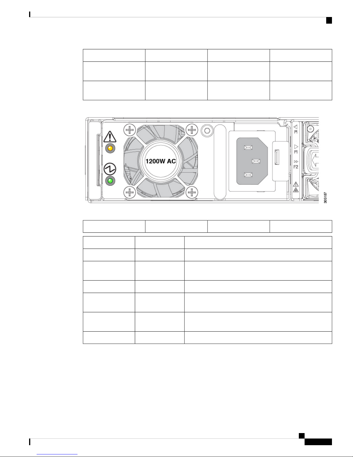
Figure 7: AC Power Supply for the Cisco UCS 6332 and UCS 6332-16UP Fabric Interconnect
Power supplies have two LEDs: one for power status and one for a failure condition.
Green power on LED2Amber fault/error LED1
DescriptionStateLED
Power supply is on and functioning properlySolid greenPower on LED
Blinking greenPower on LED
3.3 V voltage standby (VSB) is on but the power supply is not
powering the other units
There is no AC power to the power supplyOffPower on LED
Solid amberFault/error LED
Power supply failure that indicates an over voltage, over current,
or over temperature
Blinking amberFault/error LED
AC power is present, 3.3 VSB is on, and the power supply is
off
Normal operationOffFault/error LED
If one power supply is installed in the chassis, but the other power supply slot is empty, a blank filler panel
should be used to cover the empty slot.
Cisco UCS 6300 Series Fabric Interconnect Hardware Installation Guide
7
Page 10

Fan Modules
Fan Modules
LED Descriptions
The fabric interconnect has status LEDs and QSFP+ port LEDs .
Table 2: Status LEDs for the Cisco UCS 6300 Series Fabric Interconnect
Product Overview
LocationColorLED
Front and rear of chassisGreen and YellowPorts
Front and rear of chassisBlueBeacon
System Status
QSFP+ port LEDs on the front of the chassis allow you to see the link status of the ports. When you press the
push button on the front panel, a QSFP+ port LED shows the link and activity status for the selected lane, and
one of the four green LEDs show which lane is selected. You can press the push button four times to check
all four lanes of each QSFP+ port. After the fourth press, all LEDs turn off, indicating that the current link
status is 40-Gbps mode, which is the default mode.
Lane Switch and LEDs
Both the Cisco UCS 6332 Fabric Interconnect and the UCS 6332-16UP Fabric Interconnect have a lane switch
button and lane LEDs that are shown in the following figure:
Front and rear of chassisGreen, Amber, or
Red
Rear of chassisAmber or RedEnvironment
Front of chassisGreen or AmberPower supply
Front of chassis, integrated in the fanGreen or AmberFan modules
Cisco UCS 6300 Series Fabric Interconnect Hardware Installation Guide
8
Page 11

Product Overview
Lane Switch and LEDs
Figure 8: Port Lane Switch, HA Ports, and LEDs
L2 highly available port2L1 highly available port1
QSFP+ lane LEDs4Lane switch3
The port lane switch operates as follows:
• The default mode of operation after bootup is 40-Gbps. The LED on each individual port QSFP+ port
indicates the 40-Gbps link status. The lane switch button is illuminated, but none of the four lane LEDs
are illuminated.
• Pressing the lane switch button for the first time causes the lane 1 LED to illuminate. The LED on each
individual QSFP+ port represents the lane 1 status of the port.
• Pressing the lane switch button for the second time causes the lane 2 LED to illuminate. The LED on
each individual QSFP+ port represents the lane 2 status of the port.
• Pressing the lane switch button for the third time causes the lane 3 LED to illuminate. The LED on each
individual QSFP+ port represents the lane 3 status of the port.
• Pressing the lane switch button for the fourth time causes the lane 4 LED to illuminate. The LED on each
individual QSFP+ port represents the lane 4 status of the port.
• Pressing the lane switch button again causes the 40-Gbps mode to be in effect again.
When you cycle the lane switch button, the LED of a QSFP+ port indicates the status of the different lanes.
If a port is configured in breakout mode, the LED for a QSFP+ port is off when the lane LEDs are off. If a
40-Gbps port is not operating in breakout mode, and if the link is up, the LED on a QSFP+ port is green when
all the lane LEDs are off. The LED turns off when you press the lane button to lane 1, 2, 3, or 4.
The QSFP+ port LEDs for ports 13 and 14 are always the same as the 40-Gbps mode status because those
two ports cannot operate in breakout mode.
Cisco UCS 6300 Series Fabric Interconnect Hardware Installation Guide
9
Page 12

Connection Ports and LEDs
Connection Ports and LEDs
Both the Cisco UCS 6332 Fabric Interconnect and the UCS 6332-16UP Fabric Interconnect have the connection
ports and LEDs shown in the following figure:
Figure 9: Connection Ports and LEDs
Product Overview
The status of the beacon and system LEDs are as follows:
Front and rearSystem status
LED
power/health at bootup and
run time
Front and rearSystem status
LED
power/health at bootup and
run time
Front and rearSystem status
LED
power/health at bootup and
run time
USB port 12RJ45 network management port1
USB port 24RJ45 console port3
System status LED6Beaconing LED and button5
DescriptionStateColorFunctionLocationLED
Chassis selectedSolid onBlueIndicate selected chassisFront and rearBeacon LED
OffBlueIndicate selected chassisFront and rearBeacon LED
Chassis not
selected
Normal operationSolid onGreenIndicate system
OffGreenIndicate system
System powered
off
System faultOnAmberIndicate system
Cisco UCS 6300 Series Fabric Interconnect Hardware Installation Guide
10
Page 13
Product Overview
Management Port LEDs
DescriptionStateColorFunctionLocationLED
LED
LED
Management Port LEDs
The status of the management ports is listed below.
System Environment LEDs
Front and rearSystem status
power/health at bootup and
run time
Front and rearSystem status
power/health at bootup and
run time
DescriptionLED StateLED Position
No linkOffLeft
Physical linkSolid greenLeft
No activityOffRight
ActivityBlinking greenRight
Solid onRedIndicate system
BlinkingRedIndicate system
Power shut down
by software
Secure boot
validation has
failed
The system environment LED states are listed below.
Solid red
QSFP Port LEDs
The QSFP port LED states are listed below.
DescriptionLED State
Minor fan alarm (a fan is missing or there is a failure)Solid amber
Major fan alarm (two or more fans are missing or have failed, or there is a fan direction
mismatch
DescriptionLED State
Enabled, but SFP not insertedYellow
Enabled and link is upGreen
Enabled, but link is not connectedOff
Power On Self Test (POST) failedBlinking yellow
Port beacon enabledBlinking yellow
Cisco UCS 6300 Series Fabric Interconnect Hardware Installation Guide
11
Page 14

L1 and L2 Port LEDs
L1 and L2 Port LEDs
The L1 and L2 port LED states are listed below.
Product Overview
DescriptionLED State
Administrative (software shutdown)Yellow
DescriptionLED StateLED Position
No linkOffLeft
Physical linkSolid greenLeft
No activityOffRight
ActivityBlinking greenRight
Supported Transceivers
The Cisco UCS 6300 Series Fabric Interconnects support SFP+ Ethernet transceivers, SFP transceivers, SFP+
transceivers, SFP+ copper twinax cables with integrated transceivers, SFP Fibre Channel transceivers, QSFP
transceivers, and QSFP cables. Except where noted, both the UCS 6332 Fabric Interconnect and the UCS
6332-16UP Fabric Interconnect support all the transceivers listed in this section.
On the Cisco UCS 6332 Fabric Interconnect, all 1-Gigabit and 10-Gigabit transceivers and twinax cables
must use a QSA module (CVR-QSFP-SFP10G) to operate in a 40-Gbps QSFP+ port. In addition, the QSA
module is required for a 40-Gbps QSFP+ port to operate at 1 Gbps or 10 Gbps.
On the Cisco UCS 6332-16UP Fabric Interconnect, all 1-Gigabit and 10-Gigabit transceivers, Fibre Channel
transceivers, and twinax cables must use a QSA module (CVR-QSFP-SFP10G) to operate in ports 17–40 (the
40-Gbps QSFP+ ports). Ports 1–16 operate as SFP+ universal ports that are capable of operating at 1- or
10-Gbps fixed Ethernet or 4-, 8-, or 16-Gbps Fibre Channel ports and do not need a QSFP to SFP+ adapter.
In addition, the QSA module is required for a 40-Gbps QSFP+ port to operate at 1 Gbps or 10 Gbps.
SFP 1-Gigabit Transceivers
The SFP 1-Gigabit Ethernet transceiver module is a bidirectional device with a transmitter and receiver in the
same physical package.
Table 3: Supported SFP Optical Transceivers
DescriptionModel
SFP-GE-T
Cisco UCS 6300 Series Fabric Interconnect Hardware Installation Guide
12
1000BASE-T standardGLC-T
1000BASE-SX short wavelength; with MDOMGLC-SX-MMD
1000BASE-T SFP (NEBS 3 ESD)—supported only
on the UCS 6332-16UP Fabric Interconnect
Page 15

Product Overview
Note
The maximum length of fiber optic runs is limited to 300 meters. This is imposed by our use of
802.3X/802.1Qbb Priority Pauses. SFP-10G-LR is supported between fabric interconnect and I/O Module,
but the 300 m limit still applies.
SFP+ Transceivers and SFP+ Copper Cables
The enhanced SFP+ 10-Gigabit Ethernet transceiver module is a bidirectional device with a transmitter and
receiver in the same physical package. It has a 20-pin connector on the electrical interface and duplex LC
connector on the optical interface.
Table 4: Supported Transceivers
SFP+ Transceivers and SFP+ Copper Cables
DescriptionProduct ID
SFP-10G-SR
SFP-10G-SR -S
SFP-10G-LR
SFP-10G-LR -S
SFP+ Copper Cables with Integrated Transceivers
SFP-H10GB-CU1M
10GBASE-SR SFP+ module (multimode fiber
[MMF])
10GBASE-SR SFP+ module (multimode fiber
[MMF], S-Class)
10GBASE-LR SFP+ module (single-mode fiber
[SMF])
10GBASE-LR SFP+ module (single-mode fiber
[SMF], S-Class)
Cisco 10G Line Extender for FEXFET-10G
10GBASE-CU SFP+ cable 1 meter, passive
10GBASE-CU SFP+ cable 2 meter, passiveSFP-H10GB-CU2M
10GBASE-CU SFP+ cable 3 meter, passiveSFP-H10GB-CU3M
10GBASE-CU SFP+ cable 5 meter, passiveSFP-H10GB-CU5M
10GBASE-CU SFP+ cable 7 meter, activeSFP-H10GB-ACU7M
10GBASE-CU SFP+ cable 10 meter, activeSFP-H10GB-ACU10M
10GBASE-AOC SFP+ cable 1 meterSFP-10G-AOC1M
10GBASE-AOC SFP+ cable 2 meterSFP-10G-AOC2M
10GBASE-AOC SFP+ cable 3 meterSFP-10G-AOC3M
10GBASE-AOC SFP+ cable 5 meterSFP-10G-AOC5M
10GBASE-AOC SFP+ cable 7 meterSFP-10G-AOC7M
Cisco UCS 6300 Series Fabric Interconnect Hardware Installation Guide
13
Page 16

QSFP Transceivers and Cables
Note
The maximum length of fiber optic runs is limited to 300 meters. This is imposed by our use of
802.3X/802.1Qbb Priority Pauses. SFP-10G-LR is supported between fabric interconnect and FEX, but the
300 m limit still applies.
QSFP Transceivers and Cables
The Cisco UCS 6300 Series Fabric Interconnects support Cisco 40GGBASE Quad Small Form Factor (QSFP)
transceiver modules.
Table 5: Supported QSFP Transceivers and Cables
Product Overview
DescriptionProduct ID
10GBASE-AOC SFP+ cable 10 meterSFP-10G-AOC10M
DescriptionModel
QSFP-40G-LR4
QSFP-40G-LR4-S
QSFP-4x10G-AC7M
QSFP-4x10G-AC10M
40GBASE-SR4 QSFP module (multimode fiber [MMF]), 100 meterQSFP-40G-SR4
40GBASE-SR4 QSFP module (multimode fiber [MMF]), 100 meterQSFP-40G-SR4-S
40GBASE Extended CSR4 QSFP module (MMF), 300 meterQSFP-40G-CSR4
Cisco 40GBASE-LR4 QSFP+ transceiver module for SMF, duplex LC
connector
Cisco 40GBASE-LR4 QSFP+ transceiver module for SMF, duplex LC
connector
Cisco QSFP40G BiDi Short-reach transceiverQSFP-40G-SR-BD
Cisco 40G Line Extender for FEXFET-40G
Cisco 40GBASE-CR4 QSFP+ to 4 10GBASE-CU SFP+ active direct-attached
breakout cable, 7 meter
Cisco 40GBASE-CR4 QSFP+ to 4 10GBASE-CU SFP+ active direct-attached
breakout cable, 10 meter
Cisco 40GBASE-CR4 SFP+ passive direct-attach copper cable, 1 meterQSFP-H40G-CU1M
Cisco 40GBASE-CR4 SFP+ passive direct-attach copper cable, 3 meterQSFP-H40G-CU3M
Cisco 40GBASE-CR4 SFP+ passive direct-attach copper cable, 5 meterQSFP-H40G-CU5M
QSFP-4SFP10G-CU1M
Cisco UCS 6300 Series Fabric Interconnect Hardware Installation Guide
14
Cisco 40GBASE-CR4 SFP+ active direct-attach copper cable, 7 meterQSFP-H40G-ACU7M
Cisco 40GBASE-CR4 SFP+ active direct-attach copper cable, 10 meterQSFP-H40G-ACU10M
Cisco 40GBASE-CR4 QSFP+ to 4 10GBASE-CU SFP+ passive direct-attach
copper transceiver assembly, 1 meter
Page 17

Product Overview
QSFP Transceivers and Cables
QSFP-4SFP10G-CU3M
QSFP-4SFP10G-CU5M
QSFP-4X10G-AOC1M
QSFP-4X10G-AOC2M
QSFP-4X10G-AOC3M
QSFP-4X10G-AOC5M
QSFP-4X10G-AOC7M
QSFP-4X10G-AOC10M
Cisco 40GBASE-CR4 QSFP+ to 4 10GBASE-CU SFP+ passive direct-attach
copper transceiver assembly, 13 meter
Cisco 40GBASE-CR4 QSFP+ to 4 10GBASE-CU SFP+ passive direct-attach
copper transceiver assembly, 5 meter
Cisco 40GBASE-AOC QSFP TO 4 SFP+ Active Optical breakout Cable, 1
meter
Cisco 40GBASE-AOC QSFP TO 4 SFP+ Active Optical breakout Cable, 2
meter
Cisco 40GBASE-AOC QSFP TO 4 SFP+ Active Optical breakout Cable, 3
meter
Cisco 40GBASE-AOC QSFP TO 4 SFP+ Active Optical breakout Cable, 5
meter
Cisco 40GBASE-AOC QSFP TO 4 SFP+ Active Optical breakout Cable, 7
meter
Cisco 40GBASE-AOC QSFP TO 4 SFP+ Active Optical breakout Cable, 10
meter
Cisco 40GBASE-AOC QSFP direct-attach Active Optical Cable, 1 meterQSFP-H40G-AOC1M
Cisco 40GBASE-AOC QSFP direct-attach Active Optical Cable, 2 meterQSFP-H40G-AOC2M
Cisco 40GBASE-AOC QSFP direct-attach Active Optical Cable, 3 meterQSFP-H40G-AOC3M
Cisco 40GBASE-AOC QSFP direct-attach Active Optical Cable, 5 meterQSFP-H40G-AOC5M
Cisco 40GBASE-AOC QSFP direct-attach Active Optical Cable, 7 meterQSFP-H40G-AOC7M
Cisco 40GBASE-AOC QSFP direct-attach Active Optical Cable, 10 meterQSFP-H40G-AOC10M
Cisco 40GBASE-AOC QSFP direct-attach Active Optical Cable, 15 meterQSFP-H40G-AOC15M
Cisco 40GBASE QSFP to SFP+ and SFP adapterCVR-QSFP-SFP10G
Note
The Cisco UCS 6332 Fabric Interconnect does not support passive copper CR4 cables in ports 27 through 32
because these ports do not support negotiate auto. All other 40-Gigabit ports on the Cisco UCS 6332 Fabric
Interconnect support passive copper CR4 cables.
The Cisco UCS 6332-16UP Fabric Interconnect does not support passive copper CR4 cables in ports 35
through 40 because these ports do not support negotiate auto. All other 40-Gigabit ports on the Cisco UCS
6332-16UP Fabric Interconnect support passive copper CR4 cables.
Cisco UCS 6300 Series Fabric Interconnect Hardware Installation Guide
15
Page 18

SFP Fibre Channel Transceivers
SFP Fibre Channel Transceivers
The Cisco UCS 6332-16UP Fabric Interconnect supports the SFP Fibre Channel transceivers listed below.
These transceivers are not supported on the UCS 6332 Fabric Interconnect.
Table 6: SFP Fiber Channel Transceivers
Note
The maximum length of fiber optic runs from the fabric interconnect to a chassis is limited to 300 meters.
This restriction is imposed by the use of 802.3X/802.1Qbb Priority Pauses.
Product Overview
DescriptionModel
4 Gbps Fibre Channel-SW SFP, LCDS-SFP-FC4G-SW
8-Gbps Fibre Channel SW SFP+, LCDS-SFP-FC8G-SW
8-Gbps Fibre Channel LW SFP+, LCDS-SFP-FC8G-LW
16-Gbps Fibre Channel SW SFP+, LCDS-SFP-FC16G-SW
Cisco UCS 6300 Series Fabric Interconnect Hardware Installation Guide
16
Page 19

Installing the Cisco UCS 6300 Series Fabric
Interconnect
• Preparing for Installation, on page 17
• Cabinet and Rack Requirements, on page 20
• Cable Management Guidelines, on page 22
• Required Equipment, on page 22
• Unpacking and Inspecting the Cisco UCS Fabric Interconnect, on page 22
• Installing the Cisco UCS Chassis or UCS Chassis in a Cabinet or Rack, on page 23
• Grounding the System, on page 27
• Starting the System, on page 32
• Replacing or Installing Components, on page 34
• Repacking the Cisco UCS Fabric Interconnect for Return Shipment, on page 43
Preparing for Installation
CHAPTER 2
Considerations and Warnings
Note
Before you install, operate, or service the system, read the Regulatory Compliance and Safety Information
for Cisco UCS for important safety information.
Warning
IMPORTANT SAFETY INSTRUCTIONS This warning symbol means danger. You are in a situation that
could cause bodily injury. Before you work on any equipment, be aware of the hazards involved with electrical
circuitry and be familiar with standard practices for preventing accidents. Use the statement number provided
at the end of each warning to locate its translation in the translated safety warnings that accompanied this
device. Statement 1071
SAVE THESE INSTRUCTIONS
Cisco UCS 6300 Series Fabric Interconnect Hardware Installation Guide
17
Page 20

Installation Options
Installing the Cisco UCS 6300 Series Fabric Interconnect
Warning
Warning
This unit is intended for installation in restricted access areas. A restricted access area can be accessed only
through the use of a special tool, lock and key, or other means of security. Statement 1017
Only trained and qualified personnel must be allowed to install, replace, or service this equipment.
Statement 1030
Note
Each new fabric interconnect requires a license. For information on licensing, see the Configuration Guide
for the version of Cisco UCS Manager that you are using. The configuration guides are available at the
following URL:
http://www.cisco.com/en/US/products/ps10281/products_installation_and_configuration_guides_list.html
Installation Options
You can install the Cisco UCS Fabric Interconnect chassis in a perforated or solid-walled EIA cabinet or an
open EIA rack (the Cisco R Series Rack is an ideal choice), using the rack-mount kit shipped with the chassis.
For instructions on installing the chassis using the rack-mount kit shipped with the chassis, see Installing the
Cisco UCS Chassis or UCS Chassis in a Cabinet or Rack, on page 23.
Airflow Considerations
The FI's cooling fans pull air front-to-rear. That is, air intake is on the fan side and air exhaust is on the port
side.
To ensure proper airflow, follow these guidelines:
• Maintain ambient airflow throughout the data center to ensure normal operation.
• Consider the heat dissipation of all equipment when determining air conditioning requirements. When
evaluating airflow requirements, take into consideration that hot air generated by equipment at the bottom
of the rack can be drawn in the intake ports of the equipment above.
• Ensure that exhaust airflow is unobstructed.
Chassis Weight
When lifting the system, follow these guidelines:
• Disconnect all power and external cables before lifting the system.
• Have two people to lift the system. The Cisco UCS 6332 weighs 22 pounds (9.9 kg). The Cisco UCS
6332 16-UP weighs 22.61 pounds (10.2 kg). The Cisco UCS 6454 weighs 25.9 pounds (11.7 kg)
• Ensure that your footing is solid and that the weight of the system is evenly distributed between your
feet.
Cisco UCS 6300 Series Fabric Interconnect Hardware Installation Guide
18
Page 21

Installing the Cisco UCS 6300 Series Fabric Interconnect
• Lift the system slowly, keeping your back straight. Lift with your legs, not with your back. Bend at the
knees, not at the waist.
Installation Guidelines
When installing the Cisco UCS Fabric Interconnect, follow these guidelines:
• Prepare the site as described in the Site Preparation Checklist, on page 71.
• Plan your site configuration and prepare the site before installing the chassis. Site Preparation Checklist,
on page 71 lists the recommended site planning tasks.
• Record the information listed in Site Preparation Checklist, on page 71 as you install and configure the
fabric interconnect.
• Ensure that there is adequate space around the chassis to allow for servicing and for adequate airflow.
Site Preparation Checklist, on page 71 lists airflow requirements.
• Ensure that the air conditioning meets the heat dissipation requirements listed in Site Preparation Checklist,
on page 71.
Installation Guidelines
Note
Jumper power cords are available for use in a cabinet. See Cabinet Jumper Power
Cords, on page 69.
• Ensure that the chassis is adequately grounded. If the chassis is not mounted in a grounded rack, Cisco
recommends connecting both the system ground on the chassis and the power supply ground to an earth
ground.
• Ensure that the site power meets the power requirements listed in Power Specifications, on page 56 If
available, you can use an uninterruptible power supply (UPS) to protect against power failures.
Avoid UPS types that use ferroresonant technology. These UPS types can become unstable with systems
such as the Cisco UCS Fabric Interconnect, which can have substantial current draw fluctuations because
of fluctuating data traffic patterns.
• Ensure that circuits are sized according to local and national codes. For North America, the power supply
requires a 15-A or 20-A circuit.
To prevent loss of input power, ensure that the total maximum loads on the circuits supplying power to
the fabric interconnect are within the current ratings for the wiring and breakers.
• Use the following screw torques (listed in Newton-metres) when installing the chassis:
• Captive screws: 4 in-lb (0.45 N m)
• M3 screws: 4 in-lb (0.45 N m)
• M4 screws: 12 in-lb (1.36 N m)
• 10-32 screws: 20 in-lb (2.26 N m)
• 12-24 screws: 30 in-lb (3.39 N m)
Cisco UCS 6300 Series Fabric Interconnect Hardware Installation Guide
19
Page 22

Required Equipment
Required Equipment
Before beginning the installation, ensure that the following items are ready:
• Number 1 and number 2 Phillips screwdrivers with torque capability
• 3/16-inch flat-blade screwdriver
• Tape measure and level
• ESD wrist strap or other grounding device
• Antistatic mat or antistatic foam
The following additional items (not found in the accessory kit) are required to ground the chassis:
• Grounding cable (6 AWG recommended), sized according to local and national installation requirements;
the required length depends on the proximity of the Cisco UCS Fabric Interconnect to proper grounding
facilities
• Crimping tool large enough to accommodate girth of lug
Installing the Cisco UCS 6300 Series Fabric Interconnect
• Wire-stripping tool
Cabinet and Rack Requirements
This section provides the requirements for the following types of cabinets and racks, assuming an external
ambient air temperature range of 0 to 104°F (0 to 40°C):
• Standard perforated cabinets (60 percent or greater perforation front and back is required; the Cisco R
Series rack is an ideal choice)
• Standard open racks
Note
If you are using an enclosed cabinet, we recommend one of the thermally validated types: standard perforated
or solid-walled with a fan tray.
Note
Do not use racks that have obstructions (such as power strips), because the obstructions could impair access
to field-replaceable units (FRUs). The Cisco RP series PDUs when mounted in a Cisco R Series Rack should
not obstruct FRU replacement.
General Requirements for Cabinets and Racks
The cabinet or rack must be one of the following types:
• Standard 19 in. (48.3 cm) (four-post EIA cabinet or rack, with mounting rails that conform to English
universal hole spacing per section 1 of ANSI/EIA-310-D-1992. See the Requirements Specific to
Perforated Cabinets. (The Cisco R Series Rack is an ideal choice.)
Cisco UCS 6300 Series Fabric Interconnect Hardware Installation Guide
20
Page 23

Installing the Cisco UCS 6300 Series Fabric Interconnect
The cabinet or rack must also meet the following requirements:
• The minimum vertical rack space per Cisco UCS 6332 chassis must be one RU (rack unit), equal to 1.75
in. (4.4 cm).
• The minimum vertical rack space per Cisco UCS 6332 16-UP chassis must be one RU (rack unit), equal
to 1.75 in. (4.4 cm).
• The minimum vertical rack space per Cisco UCS 6454 chassis must be one RU (rack unit), equal to 1.75
in. (4.4 cm).
• The width between the rack-mounting rails must be at least 17.72 in. (45.0 cm) if the rear of the chassis
is not attached to the rack. For four-post EIA racks, this is the distance between the two front rails.
• For four-post EIA cabinets (perforated):
• The minimum spacing for the bend radius for fiber-optic cables should have the front-mounting
rails of the cabinet offset from the front door by a minimum of 3 in. (7.6 cm), and a minimum of 5
in. (12.7 cm) if cable management brackets are installed on the front of the chassis.
• The distance between the outside face of the front mounting rail and the outside face of the back
mounting rail should be 23.5 to 34.0 in. (59.7 to 86.4 cm) to allow for rear-bracket installation.
Requirements Specific to Perforated Cabinets
• A minimum of 2.5 in. (6.4 cm) of clear space should exist between the side edge of the chassis and
the side wall of the cabinet. No sizeable flow obstructions should be immediately in the way of
chassis air intake or exhaust vents.
Note
Optional jumper power cords are available for use in a cabinet.
Requirements Specific to Perforated Cabinets
A perforated cabinet is defined here as a cabinet with perforated front and rear doors and solid side walls. In
addition to the requirements listed in the General Requirements for Cabinets and Racks, on page 20, perforated
cabinets must meet the following requirements:
• The front and rear doors must have at least a 60 percent open area perforation pattern, with at least 15
square inches of open area per rack unit of door height.
• The roof should be perforated with at least a 20 percent open area.
• The cabinet floor should be open or perforated to enhance cooling.
The Cisco R Series racks meet or exceed all these requirements.
Requirements Specific to Standard Open Racks
In addition to the requirements listed in the General Requirements for Cabinets and Racks, on page 20, if
mounting the chassis in an open rack (no side panels or doors), the minimum vertical rack space per chassis
must be one RU (rack unit), equal to 1.75 in. (4.4 cm).
The Cisco R Series racks meet or exceed all these requirements.
Cisco UCS 6300 Series Fabric Interconnect Hardware Installation Guide
21
Page 24

Cable Management Guidelines
Cable Management Guidelines
To help with cable management, you might want to allow additional space in the rack above and below the
chassis to make it easier to route as many as 56 fiber or copper cables through the rack.
Required Equipment
Before beginning the installation, ensure that the following items are ready:
• Number 1 and number 2 Phillips screwdrivers with torque capability
• 3/16-inch flat-blade screwdriver
• Tape measure and level
• ESD wrist strap or other grounding device
• Antistatic mat or antistatic foam
Installing the Cisco UCS 6300 Series Fabric Interconnect
The following additional items (not found in the accessory kit) are required to ground the chassis:
• Grounding cable (6 AWG recommended), sized according to local and national installation requirements;
the required length depends on the proximity of the Cisco UCS Fabric Interconnect to proper grounding
facilities
• Crimping tool large enough to accommodate girth of lug
• Wire-stripping tool
Unpacking and Inspecting the Cisco UCS Fabric Interconnect
Caution
When handling chassis components, wear an ESD strap and handle modules by the carrier edges only. An
ESD socket is provided on the chassis. For the ESD socket to be effective, the chassis must be grounded
through the power cable, the chassis ground, or the metal-to-metal contact with a grounded rack.
Tip
Keep the shipping container in case the chassis requires shipping in the future.
Note
The interconnect is thoroughly inspected before shipment. If any damage occurred during transportation or
any items are missing, contact your customer service representative immediately.
Cisco UCS 6300 Series Fabric Interconnect Hardware Installation Guide
22
Page 25

Installing the Cisco UCS 6300 Series Fabric Interconnect
Procedure
Step 1 Compare the shipment to the equipment list provided by your customer service representative and verify that
you have received all items, including the following:
• Grounding lug kit
• Rack-mount kit
• ESD wrist strap
• Cables with connectors
• Any optional items ordered
Step 2 Check for damage and report any discrepancies or damage to your customer service representative. Have the
following information ready:
• Invoice number of shipper (see packing slip)
• Model and serial number of the damaged unit
Installing the Cisco UCS Chassis or UCS Chassis in a Cabinet or Rack
• Description of damage
• Effect of damage on the installation
Installing the Cisco UCS Chassis or UCS Chassis in a Cabinet
or Rack
This section describes how to use the rack-mount kit provided with the chassis to install Cisco UCS into a
cabinet or rack that meets the requirements described in Cabinet and Rack Requirements, on page 20. All
Cisco UCS Fabric Interconnects use the same installation procedure.
Caution
If the rack is on wheels, ensure that the brakes are engaged or that the rack is otherwise stabilized.
This table lists the items contained in the rack-mount kit provided with the chassis.
Table 7: Chassis Rack-Mount Kit
Part DescriptionQuantity
Rack-mount brackets2
M4x0.7 x 8-mm Phillips countersink screws12
10-32 cage nuts10
10-32 x 3/4-inch Phillips pan-head screws10
Cisco UCS 6300 Series Fabric Interconnect Hardware Installation Guide
23
Page 26

Installing the Cisco UCS Chassis or UCS Chassis in a Cabinet or Rack
Procedure
Step 1 Install the front rack-mount brackets as follows:
Installing the Cisco UCS 6300 Series Fabric Interconnect
Part DescriptionQuantity
Rack-mount guides2
Slider rails2
Note
The port side of the FI is the rear and it faces the rear of the rack. The fan side of the FI is the front
and it faces the front of the rack. Cooling fans pull air front-to-rear. That is, air intake is on the fan
side and air exhaust is on the port side.
a) Position a front rack-mount bracket against the chassis and align the screw holes as shown below. You
can attach the front rack-mount bracket at the front or the rear of the chassis, depending on which side
you want to locate on the cold aisle. Then attach the front rack-mount bracket to the chassis with four M4
screws.
Note
You can align any four of the holes in the front rack-mount bracket to four of the six screw
holes on the side of the chassis. The holes that you use depend on the requirements of your rack
and the amount of clearance required for interface cables and power supply handles.
b) Repeat Step 1 for the other front rack-mount bracket on the other side of the chassis.
Figure 10: Attaching the Rack-Mount Brackets to the Chassis
1
Cisco UCS 6300 Series Fabric Interconnect Hardware Installation Guide
24
aligned to the rear of the
chassis
2Front rack-mount bracket
Four M4 screws used to
attach the bracket to the
chassis
Page 27

Installing the Cisco UCS 6300 Series Fabric Interconnect
Installing the Cisco UCS Chassis or UCS Chassis in a Cabinet or Rack
3
4Rear rack-mount guide
aligned to the front of the
Two M4 screws used to
attach the brackets
chassis
5
6Front rack-mount bracket
aligned to the front of the
chassis
8Rear rack-mount guide7
Four M4 screws used to
attach the bracket to the
chassis
Two M4 screws used to
attach the bracket to the
chassis
Step 2 Install the rear rack-mount guides on the chassis as follows:
a) Align the two screw holes on a rear rack-mount bracket to the middle two screw holes in the remaining
six screw holes on a side of the chassis. If you are aligning the bracket to holes that are near the front end
of the chassis, see callout 3 in the previous figure. Otherwise, see callout 7 in the previous figure.
b) Attach the bracket to the chassis with two of the flat-head M4 screws. See callout 4 or 8 in the previous
figure.
c) Repeat Step 2 with the other rear rack-mount bracket on the other side of the chassis.
Step 3 Attach the slider rails to the rack. Use 2 12-24 screws or 2 10-32 screws, depending on the rack rail thread
type. For racks with square holes, insert the 12-24 cage nuts in position behind the mounting holes in the
slider rails.
a) Repeat with the other slider rail on the other side of the rack.
b) Use the tape measure and level to verify that the rails are horizontal and at the same height.
Figure 11: Installing the Slider Rails
Step 4 Insert the chassis into the rack:
a) Holding the chassis with both hands, position the two rear rack-mount brackets on the chassis between
the two posts that do not have slider rails attached to them (see the following figure).
b) Align the two rear rack-mount guides on either side of the chassis with the slider rails installed in the rack.
Slide the rack-mount glides onto the slider rails, and then gently slide the chassis all the way into the rack.
If the chassis does not slide easily, try realigning the rack-mount glides on the slider rails.
Cisco UCS 6300 Series Fabric Interconnect Hardware Installation Guide
25
Page 28

Installing the Cisco UCS Chassis or UCS Chassis in a Cabinet or Rack
Figure 12: Sliding the Chassis Into the Rack
Installing the Cisco UCS 6300 Series Fabric Interconnect
Step 5 Stabilize the chassis in the rack by attaching the front rack-mount brackets to the front rack-mounting rails:
a) Insert 2 screws (12-24 or 10-32, depending on rack type) in each the two front rack-mount brackets (using
a total of four screws) and into the threaded holes in the vertical rack-mounting rail.
b) Repeat for the front rack-mount bracket on the other side of the chassis.
Figure 13: Attaching the Chassis to the Rack
Cisco UCS 6300 Series Fabric Interconnect Hardware Installation Guide
26
Page 29

Installing the Cisco UCS 6300 Series Fabric Interconnect
Grounding the System
Proper Grounding Practices
Grounding is one of the most important parts of equipment installation. When you properly ground systems
during installation, you reduce or prevent shock hazards, equipment damage due to transients, and data
corruption.
Table 8: Proper Grounding Guidelines
Grounding the System
Environment
to direct lightning strikes.
For example, some places in the
United States, such as Florida, are
subject to more lightning strikes
than are other areas.
an area where lightning storms
frequently occur but is not subject
to direct lightning strikes.
mix of information technology
equipment and industrial
equipment, such as welding.
subject to natural environmental
noise or man made industrial noise.
This building contains a standard
office environment. This
installation has a history of
malfunction due to electromagnetic
noise.
Level
HighCommercial building is subjected
HighCommercial building is located in
Medium to highCommercial building contains a
MediumExisting commercial building is not
Grounding RecommendationsElectromagnetic Noise Severity
All lightning protection devices
must be installed in strict
accordance with manufacturer
recommendations. Conductors
carrying lightning current should
be spaced away from power and
data lines in accordance with
applicable recommendations and
codes. Best grounding
recommendations must be closely
followed.
Best grounding recommendations
must be closely followed.
Best grounding recommendations
must be closely followed.
Determine source and cause of
noise if possible, and mitigate as
closely as possible at the noise
source or reduce coupling from the
noise source to the affected
equipment. Best grounding
recommendations must be closely
followed.
Cisco UCS 6300 Series Fabric Interconnect Hardware Installation Guide
27
Page 30

Preventing Electrostatic Discharge Damage
Installing the Cisco UCS 6300 Series Fabric Interconnect
Environment
Grounding RecommendationsElectromagnetic Noise Severity
Level
LowNew commercial building is not
subject to natural environmental
noise or man-made industrial noise.
This building contains a standard
office environment.
Electromagnetic noise problems are
not anticipated, but installing a
grounding system in a new building
is often the least expensive route
and the best way to plan for the
future. Best grounding
recommendations should be
followed as closely as possible.
LowExisting commercial building is not
subject to natural environmental
noise or man-made industrial noise.
This building contains a standard
office environment.
Electromagnetic noise problems are
not anticipated, but installing a
grounding system is always
recommended. Best grounding
recommendations should be
followed as much as possible.
Note
In all situations, grounding practices must comply with local National Electric Code (NEC) requirements or
local laws and regulations.
Note
Always ensure that all of the modules are completely installed and that the captive installation screws are
fully tightened. In addition, ensure that all I/O cables and power cords are properly seated. These practices
are normal installation practices and must be followed in all installations.
Preventing Electrostatic Discharge Damage
Electrostatic discharge (ESD) damage, which can occur when modules or other devices are improperly handled,
results in intermittent or complete failures. Modules consist of printed circuit boards that are fixed in metal
carriers. Electromagnetic interference (EMI) shielding and connectors are integral components of the carrier.
Although the metal carrier helps to protect the board from ESD, always use an ESD grounding strap when
handling modules.
For preventing ESD damage, follow these guidelines:
• Always use an ESD wrist strap and ensure that it makes maximum contact with bare skin.
• ESD grounding straps are available with banana plugs, metal spring clips, or alligator clips. All Cisco
UCS 6300 Series Fabric Interconnect chassis are equipped with a banana plug connector (identified by
the ground symbol next to the connector) somewhere on the front panel. We recommend that you use a
personal ESD grounding strap equipped with a banana plug.
• If you choose to use the disposable ESD wrist strap supplied with most field-replaceable units or an ESD
wrist strap equipped with an alligator clip, you must attach the system ground lug to the chassis in order
to provide a proper grounding point for the ESD wrist strap.
Cisco UCS 6300 Series Fabric Interconnect Hardware Installation Guide
28
Page 31

Installing the Cisco UCS 6300 Series Fabric Interconnect
Note
This system ground is also referred to as the network equipment building system
(NEBS) ground.
• If your chassis does not have the system ground attached, you must install the system ground lug. See
the Establishing the System Ground, on page 30 for installation instructions and location of the chassis
system ground pads.
Note
You do not need to attach a supplemental system ground wire to the system
ground lug; the lug provides a direct path to the bare metal of the chassis.
Before you install the system ground lug, you must correctly attach the ESD wrist strap.
Procedure
Preventing Electrostatic Discharge Damage
Step 1 Attach the ESD wrist strap to bare skin as follows:
a) If you are using the ESD wrist strap supplied with the FRUs, open the wrist strap package and unwrap
the ESD wrist strap. Place the black conductive loop over your wrist and tighten the strap so that it makes
good contact with your bare skin.
b) Open the package and remove the ESD wrist strap. Locate the end of the wrist strap that attaches to your
body and secure it to your bare skin.
Step 2 Grasp the spring or alligator clip and momentarily touch the clip to a bare metal spot, such as an unpainted
rack rail, to safely dissipate any built-up static charge to the entire rack.
Step 3 Attach the ESD strap to the system ground in one of the following ways:
• If you are using a wrist strap that is equipped with a plug, insert the plug into an open screw hole used
for the grounding lug.
• If you are using a wrist strap with spring or alligator clips, attach either the spring clip or the alligator
clip to the ground lug screw:
If you are using the ESD wrist strap that is supplied with the FRUs, squeeze the spring clip jaws open, position
the spring clip to one side of the system ground lug screw head, and slide the spring clip over the lug screw
head so that the spring clip jaws close behind the lug screw head.
Note
The spring clip jaws do not open wide enough to fit directly over the head of the lug screw or the
lug barrel.
If you are using an ESD wrist strap that is equipped with an alligator clip, attach the alligator clip
directly over the head of the system ground lug screw or to the system ground lug barrel.
In addition, follow these guidelines when handling components:
• Handle carriers by available handles or edges only; avoid touching the printed circuit boards or connectors.
Cisco UCS 6300 Series Fabric Interconnect Hardware Installation Guide
29
Page 32

Establishing the System Ground
• Place a removed component board-side-up on an antistatic surface or in a static-shielding container. If
• Never attempt to remove the printed circuit board from the metal carrier.
Installing the Cisco UCS 6300 Series Fabric Interconnect
you plan to return the component to the factory, immediately place it in a static-shielding container.
Caution
For safety, periodically check the resistance value of the antistatic strap. The
measurement should be between 1 and 10 megohm (Mohm).
Establishing the System Ground
Note
This system ground is referred to as the network equipment building system (NEBS) ground.
You must use the NEBS ground on AC-powered systems if you are installing this equipment in a U.S. or
European Central Office.
The NEBS ground provides additional grounding for EMI shielding requirements and grounding for the
low-voltage supplies (DC-DC converters) on the modules, and is intended to satisfy the Telcordia Technologies
NEBS requirements for supplemental bonding and grounding connections. You must observe the following
system grounding guidelines for your chassis:
• You must install the NEBS ground connection with any other rack or system power ground connections
that you make. The system ground connection is required if this equipment is installed in a U.S. or
European Central Office.
• You must connect both the NEBS ground connection and the power supply ground connection to an
earth ground. The NEBS ground connection is required if this equipment is installed in a U.S. or European
Central Office.
• You do not need to power down the chassis because this device is equipped with AC-input power supplies.
Required Tools and Equipment
To connect the system ground, you need the following tools and materials:
• Grounding lug—A two-hole standard barrel lug. Supports up to 6 AWG wire. Supplied as part of accessory
kit.
• Grounding screws—Two M4 x 8mm (metric) pan-head screws. Supplied as part of the accessory kit.
• Grounding wire—Not supplied as part of accessory kit. The grounding wire should be sized according
to local and national installation requirements. Depending on the power supply and system, a 12 AWG
to 6 AWG copper conductor is required for U.S. installations. Commercially available 6 AWG wire is
recommended. The length of the grounding wire depends on the proximity of the chassis to proper
grounding facilities.
• No. 1 Phillips head screwdriver.
• Crimping tool to crimp the grounding wire to the grounding lug.
Cisco UCS 6300 Series Fabric Interconnect Hardware Installation Guide
30
Page 33

Installing the Cisco UCS 6300 Series Fabric Interconnect
• Wire-stripping tool to remove the insulation from the grounding wire.
Grounding the Fabric Interconnect
The chassis has a grounding pad with two threaded M4 holes for attaching a grounding lug.
Grounding the Fabric Interconnect
Warning
Caution
Caution
Warning
Caution
When installing or replacing the unit, the ground connection must always be made first and disconnected last.
Statement 1046
We recommend grounding the chassis, even if the rack is already grounded.
All power supplies must be grounded. The receptacles of the AC power cables used to provide power to the
chassis must be the grounding type, and the grounding conductors should connect to protective earth ground
at the service equipment.
When installing or replacing the unit, the ground connection must always be made first and disconnected last.
Statement 1046
Grounding the chassis is required if you are using DC power supplies, even if the rack is already grounded.
A grounding pad with two threaded M4 holes is provided on the chassis for attaching a grounding lug. The
ground lug must be NRTL listed. In addition, the copper conductor (wires) must be used and the copper
conductor must comply with NEC code.
Procedure
Step 1 Use a wire-stripping tool to remove approximately 0.75 inches (19 mm) of the covering from the end of the
grounding cable.
Step 2 Insert the stripped end of the grounding cable into the open end of the grounding lug.
Step 3 Use the crimping tool to secure the grounding cable in the grounding lug.
Step 4 Remove the adhesive label from the grounding pad on the chassis.
Cisco UCS 6300 Series Fabric Interconnect Hardware Installation Guide
31
Page 34

Starting the System
Installing the Cisco UCS 6300 Series Fabric Interconnect
Figure 14: Connecting the System Ground
Step 5 Place the grounding lug against the grounding pad so that there is solid metal-to-metal contact, and insert the
two M4 screws with washers through the holes in the grounding lug and into the grounding pad.
Step 6 Ensure that the lug and cable do not interfere with other equipment.
Step 7 Prepare the other end of the grounding cable and connect it to an appropriate grounding point in your site to
ensure adequate earth ground.
Starting the System
Note
Do not connect the Ethernet port to the LAN until the initial system configuration has been performed. For
instructions on configuring the system, see the Configuration Guide for the version of Cisco UCS Manager
that you are using. The configuration guides are available at this URL:
DescriptionItem
Grounding Pad1
Grounding Cable2
M4 Screws3
http://www.cisco.com/c/en/us/support/servers-unified-computing/ucs-manager/
products-installation-and-configuration-guides-list.html
Cisco UCS 6300 Series Fabric Interconnect Hardware Installation Guide
32
Page 35

Installing the Cisco UCS 6300 Series Fabric Interconnect
Starting the System
Warning
When installing or replacing the unit, the ground connection must always be made first and disconnected last.
Statement 1046
Warning
The plug-socket combination must be accessible at all times, because it serves as the main disconnecting
device. Statement 1019
Procedure
Step 1 Verify that empty power supply slots have filler panels installed, the faceplates of all modules are flush with
the front of the chassis, and the captive screws of the power supplies, fan module, and all expansion modules
are tight.
Step 2 Verify that the power supply and the fan modules are installed. (See Replacing or Installing Power Supplies,
on page 34 if necessary.)
Note
Depending on the outlet receptacle on your power distribution unit, you may need the optional
jumper power cord to connect the Cisco UCS Fabric Interconnect to your outlet receptacle. See
Cabinet Jumper Power Cords, on page 69.
Step 3 Ensure that the chassis is adequately grounded, and that the AC or DC power available has the required power
voltages (see Power Specifications, on page 56). For a DC installation, see Wiring a DC Power Connector,
on page 36 to correctly wire the DC connector before applying a DC cable.
Step 4 For a first-time installation, you will need to work with your network manager to determine the following
parameters:
• System name
• Password for the admin account. Choose a strong password that meets the guidelines for Cisco UCS
Manager passwords. This password can not be blank.
• Management port IP address and subnet mask
• Default gateway IP address
• DNS server IP address (optional)
• Domain name for the system (optional)
Step 5 Connect a PC or laptop directly to the console port of the primary or standalone fabric interconnect. In a
cluster configuration, the primary will be the fabric interconnect that powers up first. The console port on the
terminal should be set to 9600 baud, 8 data bits, no parity, 1 stop bit.
Step 6 If the fabric interconnect will be running in a cluster with another fabric interconnect, you will need to connect
Ethernet cables between the L1 and L2 ports. Port L1 on fabric interconnect A connects to L1 on fabric
interconnect B, and Port L2 on fabric interconnect A connects to L2 on fabric interconnect B. If the fabric
interconnect and the UCS instance will be in standalone mode this will not be necessary.
Step 7 Connect the power cable to a power source. The system should power on as soon as you connect the AC
power cable, HVDC power cable, or DC power connector.
Cisco UCS 6300 Series Fabric Interconnect Hardware Installation Guide
33
Page 36

Installing the Cisco UCS 6300 Series Fabric Interconnect
Replacing or Installing Components
Step 8 Listen for the fans; they should begin operating when you plug in the power cable.
Step 9 After the system boots, verify that the LED operation is as follows:
• Fan module—Status LED is green.
• Power supply—Status LED is green.
• After initialization, the system status LED is green, indicating that all chassis environmental monitors
are reporting that the system is operational. If this LED is orange or red, then at least one environmental
monitor is reporting a problem.
• The Link LEDs for the Ethernet connector should not be on unless the cable is connected.
Note
Step 10 If there is a problem, try removing and reinstalling a component that is not operating correctly. If it still does
not operate correctly, contact your customer service representative for a replacement.
Note
Step 11 Verify that the system software has booted and that the system has initialized without error messages.
If you cannot resolve an issue, contact your customer service representative.
Step 12 Complete the worksheets provided in Site Preparation Checklist, on page 71 for future reference.
Step 13 Configure the primary fabric interconnect as described in thr Configuration Guide for the version of Cisco
UCS Manager that you are using. The configuration guides are available at this URL: http://www.cisco.com/
c/en/us/support/servers-unified-computing/ucs-manager/products-installation-and-configuration-guides-list.html
Step 14 Power up the primary fabric interconnect, connect the terminal to the console port, and configure the secondary
fabric interconnect as described in the Cisco UCS Manager Configuration Guide.
The link LEDs for the Fibre Channel ports remain yellow until the ports are enabled, and the LED
for the Ethernet connector port remains off until the port is connected.
If you purchased this product through a Cisco reseller, contact the reseller directly for technical
support. If you purchased this product directly from Cisco, contact Cisco Technical Support at this
URL: http://www.cisco.com/en/US/support/tsd_cisco_worldwide_contacts.html.
Replacing or Installing Components
Caution
Replacing or Installing Power Supplies
34
To prevent ESD damage, wear grounding wrist straps during these procedures and handle modules by the
carrier edges only.
The Cisco UCS Fabric Interconnect supports two front-end AC, DC, or HVDC power supplies, but may be
used with one power supply. Mixing of AC, DC, or HVDC power supplies is not supported. If you need to
replace an existing power supply, follow the procedures that explain how to remove and install power supplies.
If you are installing a new power supply where one did not exist before, follow the installation procedure.
See Installing a Power Supply, on page 35.
Cisco UCS 6300 Series Fabric Interconnect Hardware Installation Guide
Page 37

Installing the Cisco UCS 6300 Series Fabric Interconnect
Note
You can replace a faulty power supply while the system is operating provided that the other power supply is
functioning.
Removing a Power Supply
Removing a Power Supply
Caution
If you are using the Cisco UCS Fabric Interconnect with one power supply, removing the power supply causes
the system to shut down. If you are using two power supplies and you remove one of them, the system continues
to operate.
Procedure
Step 1 Ensure that the system (earth) ground connection has been made.
Step 2 Remove the AC power cord, HVDC power cord, or DC wiring connector.
Step 3 Grasp the power supply handle with your left hand.
Step 4 Push against the release latch with your left thumb and slide the power supply out of the chassis.
Step 5 Place your right hand under the power supply to support it while you slide it out of the chassis.
Step 6 If you are not replacing the power supply, install a blank power supply filler panel. If you are replacing the
power supply, proceed to Installing a Power Supply, on page 35.
Installing a Power Supply
Procedure
Step 1 Ensure that the system (earth) ground connection has been made.
Step 2 If the power supply bay has a filler panel, press the latches on the sides of the filler panel, and then slide it
out of the power supply bay.
Step 3 Hold the power supply by the handle and position it so that the release latch is on the right, and then slide it
into the power supply bay, ensuring that the power supply is fully seated in the bay.
Step 4 Plug the AC power cable, HVDC power cable, or DC wiring connector into the inlet receptacle at the rear of
the chassis. For a DC installation, you should secure the plug to the power supply by tightening both captive
screws on the plug.
Note
Depending on the outlet receptacle on your power distribution unit, you may need the optional
jumper power cord to connect the Cisco UCS Fabric Interconnect to your outlet receptacle. See
Cabinet Jumper Power Cords, on page 69.
Step 5 Connect the other end of the power cable or cables to a power source. DC sources should connect negative
(black wire) and then positive (red wire) connections.
Cisco UCS 6300 Series Fabric Interconnect Hardware Installation Guide
35
Page 38

Wiring a DC Power Connector
In a system with dual power supplies, connect each power supply to a separate power source. In case of a
power source failure, the second source will most likely still be available.
Step 6 Verify power supply operation by checking that the power supply LED is green.
Wiring a DC Power Connector
Installing the Cisco UCS 6300 Series Fabric Interconnect
Warning
Warning
Warning
Warning
Warning
A readily accessible two-poled disconnect device must be incorporated in the fixed wiring. Statement 1022
This product requires short-circuit (overcurrent) protection, to be provided as part of the building installation.
Install only in accordance with national and local wiring regulations. Statement 1045
When installing or replacing the unit, the ground connection must always be made first and disconnected last.
Statement 1046
Installation of the equipment must comply with local and national electrical codes. Statement 1074
Hazardous voltage or energy may be present on DC power terminals. Always replace cover when terminals
are not in service. Be sure uninsulated conductors are not accessible when cover is in place. Statement 1075
Before installing a DC power supply to the fabric interconnect, you must attach DC connection wires that
you provide (10 GA recommended) to the DC power connector included in the DC power supply’s accessory
kit.
Procedure
Step 1 Using a 1/8-inch flat head screwdriver or No. 1 Phillips head screwdriver, loosen the set screws on the connector
to freely accept the power wires. The connector will accept 8-24 AWG wires. Use what your local electrical
code requires.
Step 2 Strip 1/2-inch of insulation off the DC wires you will use.
Step 3 Insert the black (DC negative) wire into the right aperture on the connector and tighten down the connection
set screw. Finger tight or about 3 ft./lbs should be sufficient.
Step 4 Insert the red (DC positive) wire into the left aperture on the connector and tighten down the connection set
screw. Do not tighten over 0.51 ft./lbs.
Cisco UCS 6300 Series Fabric Interconnect Hardware Installation Guide
36
Page 39

+
2
2
1
330338
Installing the Cisco UCS 6300 Series Fabric Interconnect
Figure 15: Wiring the DC Power Connector
Fan Modules
Fan Modules
Replacing a Fan Module
Warning
Step 1 Ensure that the system (earth) ground connection has been made.
Step 2 Loosen the captive screws on the fan module by turning them counterclockwise, using a flat-blade or number 2
Step 3 Squeeze together the handles of the fan module and pull it outward.
Step 4 Pull the fan module clear of the chassis and set it down on antistatic foam or place it in an antistatic bag.
Step 5 Hold the replacement fan module with the LED at the bottom.
Step 6 Place the fan module into the front chassis cavity so it rests on the chassis. Then push the fan module into the
Step 7 Listen for the fans. If the system is powered on, you should immediately hear them operating. If you do not
Step 8 Verify that the LED is green. If the LED is not green, one or more fans are faulty. If this occurs, contact your
When removing the fan tray, keep your hands and fingers away from the spinning fan blades. Let the fan
blades completely stop before you remove the fan tray. Statement 258
Procedure
Phillips head screwdriver if required.
chassis as far as it can go and the captive screw makes contact with the chassis. Tighten the captive screw.
hear them, ensure that the fan module is inserted completely in the chassis and the faceplate is flush with the
outside surface of the chassis.
customer service representative for a replacement part.
Cisco UCS 6300 Series Fabric Interconnect Hardware Installation Guide
37
Page 40

Preparing a Fabric Interconnect for Removal
Installing the Cisco UCS 6300 Series Fabric Interconnect
Note
If you purchased this product through a Cisco reseller, contact the reseller directly for technical
support. If you purchased this product directly from Cisco, contact Cisco Technical Support at this
URL: http://www.cisco.com/en/US/support/tsd_cisco_worldwide_contacts.html.
Preparing a Fabric Interconnect for Removal
Removing a standby fabric interconnect is non-disruptive in a redundant Cisco UCS configuration. Removing
an active fabric interconnect will cause the standby fabric interconnect to become active with minimal or no
disruption.
Caution
Step 1 Use Cisco UCS Manager to perform the following tasks:
Be aware that if you remove both the active and standby fabric interconnect, or the sole fabric interconnect
from a standalone system, you are shutting down the entire Cisco UCS domain.
Procedure
a) Back up your Cisco UCS Manager configuration.
b) Shut down the OS on all servers in the Cisco UCS domain.
c) Disable the Smart Call Home feature in the Cisco UCS domain.
d) Decommission every attached chassis in the Cisco UCS domain.
For details, see the Configuration Guide for the version of Cisco UCS Manager that you are using. The
configuration guides are available at this URL: http://www.cisco.com/c/en/us/support/
servers-unified-computing/ucs-manager/products-installation-and-configuration-guides-list.html.
Step 2 Power down every attached chassis as described in the Cisco UCS 5108 Server Chassis Hardware Installation
Guide.
When powering down and removing clustered fabric interconnects, remove the secondary fabric interconnect
first, and then remove the primary fabric interconnect.
Removing a Cisco UCS Fabric Interconnect
Caution
The slider rail and front rack-mount brackets do not have a stop mechanism when sliding in and out. If the
front of the chassis is unfastened from the rack and the chassis slides forward on the slider rails, it may slip
off the end of the rails and fall out of the rack.
Cisco UCS 6300 Series Fabric Interconnect Hardware Installation Guide
38
Page 41

Installing the Cisco UCS 6300 Series Fabric Interconnect
Removing a Cisco UCS 6332 16-UP Fabric Interconnect
Procedure
Step 1 Ensure that the weight of the Cisco UCS Fabric Interconnect is fully supported and that the chassis is being
held by another person.
Step 2 Remove the two screws holding the grounding cable to the chassis.
Step 3 Disconnect the power cord and the console cables.
Step 4 Disconnect all cables that are connected to SFP28 transceivers.
Step 5 Remove the screws fastening the front rack-mount brackets to the mounting rails.
Step 6 Gently slide the Cisco UCS Fabric Interconnect toward you, off of the slider rails and out of the rack.
Removing a Cisco UCS 6332 16-UP Fabric Interconnect
Caution
Step 1 Ensure that the weight of the Cisco UCS 6332 16-UP is fully supported and that the chassis is being held by
Step 2 Remove the two screws holding the grounding cable to the chassis.
Step 3 Disconnect the power cord and the console cables.
Step 4 Disconnect all cables that are connected to SFP+ transceivers.
Step 5 Remove the screws fastening the front rack-mount brackets to the mounting rails.
Step 6 Gently slide the Cisco UCS 6332 16-UP toward you, off of the slider rails and out of the rack.
The slider rail and front rack-mount brackets do not have a stop mechanism when sliding in and out. If the
front of the chassis is unfastened from the rack and the chassis slides forward on the slider rails, it may slip
off the end of the rails and fall out of the rack.
Procedure
another person.
Replacing a Fabric Interconnect
Use the following procedure when you need to replace a single fabric interconnect with the same model of
fabric interconnect.
Use Cisco UCS Manager, either the GUI or the CLI, to perform the software-related tasks mentioned in the
following procedure. For additional information, refer to the Cisco UCS Manager Getting Started Guide, the
Cisco UCS Manager Infrastructure Management Guide, and the instructional videos available at this URL:
http://www.cisco.com/c/en/us/support/servers-unified-computing/ucs-manager/
products-installation-and-configuration-guides-list.html
As a best practice, perform a full configuration backup before replacing the fabric interconnect.
Cisco UCS 6300 Series Fabric Interconnect Hardware Installation Guide
39
Page 42

Installing the Cisco UCS 6300 Series Fabric Interconnect
Replacing a Fabric Interconnect
Procedure
Step 1 Contact Cisco TAC or your Cisco Sales representative to have them transfer the license to the replacement
fabric interconnect.
Step 2 Label the ports and the cables that you using so that you can refer to this information later. The cabling and
port numbering should be same for the replacement fabric interconnect.
Step 3 Log into UCS Manager and verify the state of the fabric interconnect, either active or subordinate. From the
CLI, enter the show cluster extended-state command. High availability (HA) should be running in UCS
Manager.
Example:
FI-A# show cluster extended-state
Cluster Id: 0x537d0580bf9911e0-0x8955000decd07984
A: UP, PRIMARY
B: UP, SUBORDINATE
A: memb state UP, lead state PRIMARY, mgmt services state: UP
B: memb state UP, lead state SUBORDINATE, mgmt services state: UP
heartbeat state PRIMARY_OK
INTERNAL NETWORK INTERFACES:
eth1, UP
eth2, UP
HA READY <<<<<<<<<<<<<←---------------- HA is READY
Detailed state of the device selected for HA storage:
Chassis 1, serial: FOX1344G1R1, state: active
Chassis 2, serial: FOX1318GDKR, state: active
FI-A#
Step 4 Back up the software configuration.
Step 5 Use the fabric evacuation procedure on the subordinate fabric interconnect to ensure there is no data traffic
impact during the hardware replacement.
Step 6 Power down the subordinate fabric interconnect by unplugging it from the power source.
Example:
FI-A# show cluster extended-state
Cluster Id: 0x537d0580bf9911e0-0x8955000decd07984
A: UP, PRIMARY
B: DOWN, INAPPLICABLE
A: memb state UP, lead state PRIMARY, mgmt services state: UP
B: memb state DOWN, lead state INAPPLICABLE, mgmt services state: DOWN
heartbeat state SECONDARY_FAILED
INTERNAL NETWORK INTERFACES:
eth1, DOWN
eth2, DOWN
HA NOT READY
Peer Fabric Interconnect is down
Detailed state of the device selected for HA storage:
Chassis 1, serial: FOX1344G1R1, state: active
Chassis 2, serial: FOX1318GDKR, state: active
FI-A#
Cisco UCS 6300 Series Fabric Interconnect Hardware Installation Guide
40
Page 43

Installing the Cisco UCS 6300 Series Fabric Interconnect
Replacing a Fabric Interconnect
Step 7 Disconnect the cables from the front and back of the fabric interconnect and remove it. Follow the instructions
in this section for removing a fabric interconnect.
Step 8 Install the replacement fabric interconnect. Follow the instructions in this section for installing the fabric
interconnect.
Step 9 Connect the management and console cables to the replacement fabric interconnect.
Step 10 Connect the L1/L2 cables that were disconnected to the replacement fabric interconnect.
Step 11 Connect the data cable according to the labels that you created in Step 2.
Step 12 Connect the power cable to the fabric interconnect and it will automatically boot and run POST tests.
---- Basic System Configuration Dialog ----
This setup utility will guide you through the basic configuration of
the system. Only minimal configuration including IP connectivity to
the Fabric interconnect and its clustering mode is performed through these steps.
Type Ctrl-C at any time to abort configuration and reboot system.
To back track or make modifications to already entered values,
complete input till end of section and answer no when prompted
to apply configuration.
Enter the configuration method. (console/gui) ? console
Installer has detected the presence of a peer Fabric interconnect.
This Fabric interconnect will be added to the cluster. Continue (y/n) ? y
Enter the admin password of the peer Fabric interconnect:
Connecting to peer Fabric interconnect... done
Retrieving config from peer Fabric interconnect... done
Peer Fabric interconnect Mgmt0 IP Address: 122.255.252.2
Peer Fabric interconnect Mgmt0 IP Netmask: 255.255.255.0
Cluster IP address : 122.255.252.1
Physical Switch Mgmt0 IPv4 address : 122.255.252.3
Apply and save the configuration (select 'no' if you want to re-enter)? (yes/no): yes
Applying configuration. Please wait.
Configuration file - Ok
Cisco UCS 6300 Series Fabric Interconnect
FI-B login:
Step 13 If necessary, upgrade the UCS Manager software. If the replacement fabric interconnect is not running the
same firmware version as the cluster, the setup utility can upgrade the firmware.
Example:
---- Basic System Configuration Dialog ----
This setup utility will guide you through the basic configuration of
the system. Only minimal configuration including IP connectivity to
the Fabric interconnect and its clustering mode is performed through
these steps.
Type Ctrl-C at any time to abort configuration and reboot system.
To back track or make modifications to already entered values,
complete input till end of section and answer no when prompted
to apply configuration.
Cisco UCS 6300 Series Fabric Interconnect Hardware Installation Guide
41
Page 44

Replacing a Fabric Interconnect
Enter the configuration method. (console/gui) ? console
Installer has detected the presence of a peer Fabric interconnect.
This Fabric interconnect will be added to the cluster. Continue (y/n) ? y
Enter the admin password of the peer Fabric interconnect:
Connecting to peer Fabric interconnect... done
Retrieving config from peer Fabric interconnect... done
Installer has determined that the peer Fabric Interconnect is
running a different firmware version than the local Fabric.
Cannot join cluster.
Local Fabric Interconnect
Peer Fabric Interconnect
Installing the Cisco UCS 6300 Series Fabric Interconnect
UCSM version : 3.1(2c)
Kernel version : 5.0(3)N2(3.12b)
System version : 5.0(3)N2(3.12b)
local_model_no : UCS-FI-6332
UCSM version : 3.1(2c)
Kernel version : 5.0(3)N2(3.12c)
System version : 5.0(3)N2(3.12c)
peer_model_no : UCS-FI-6332
Do you wish to update firmware on this Fabric Interconnect to the
Peer's version? (y/n): y
Updating firmware of Fabric Interconnect.......
[ Please don't press Ctrl+c while updating firmware ]
Updating images
Please wait for firmware update to complete.
<output truncated>
Install has been successful.
Firmware Updation Successfully Completed. Please wait to enter the IP address
Peer Fabric interconnect Mgmt0 IPv4 Address: xx.xx.xx.xx
Peer Fabric interconnect Mgmt0 IPv4 Netmask: xx.xx.xx.xx
Cluster IPv4 address : xx.xx.xx.xx
Peer FI is IPv4 Cluster enabled. Please Provide Local
Fabric Interconnect Mgmt0 IPv4 Address
Physical Switch Mgmt0 IP address : xx.xx.xx.xx
Apply and save the configuration (select 'no' if you want to re-enter)?
(yes/no): yes
Applying configuration. Please wait.
Fri Dec 9 19:57:15 UTC 2016
Configuration file - Ok
Step 14 Enter the show cluster extended-state command to revalidate the cluster state and verify that HA is ready.
Example:
FI-A# show cluster extended-state
Cluster Id: 0x537d0580bf9911e0-0x8955000decd07984
A: UP, PRIMARY
B: UP, SUBORDINATE
Cisco UCS 6300 Series Fabric Interconnect Hardware Installation Guide
42
Page 45

Installing the Cisco UCS 6300 Series Fabric Interconnect
Repacking the Cisco UCS Fabric Interconnect for Return Shipment
A: memb state UP, lead state PRIMARY, mgmt services state: UP
B: memb state UP, lead state SUBORDINATE, mgmt services state: UP
heartbeat state PRIMARY_OK
INTERNAL NETWORK INTERFACES:
eth1, UP
eth2, UP
HA READY <<<<<<<<<<<<<←---------------- HA is READY
Detailed state of the device selected for HA storage:
Chassis 1, serial: FOX1344G1R1, state: active
Chassis 2, serial: FOX1318GDKR, state: active
FI-A#
Step 15 Disable fabric evacuation and verify that traffic is flowing in both fabric interconnects.
Step 16 Apply the port license to the fabric interconnect.
Repacking the Cisco UCS Fabric Interconnect for Return
Shipment
If you need to return the fabric interconnect, remove the chassis from the rack by following the steps in
Removing a Cisco UCS Fabric Interconnect, on page 38, and repack it for shipment. If possible, use the
original packing materials and container to repack the chassis. Contact your Cisco customer service
representative to arrange for return shipment to Cisco.
Cisco UCS 6300 Series Fabric Interconnect Hardware Installation Guide
43
Page 46

Repacking the Cisco UCS Fabric Interconnect for Return Shipment
Installing the Cisco UCS 6300 Series Fabric Interconnect
Cisco UCS 6300 Series Fabric Interconnect Hardware Installation Guide
44
Page 47

Connecting the Cisco UCS 6300 Series Fabric
Interconnect
• Preparing for Network Connections, on page 45
• Connecting to the Console Port, on page 46
• Connecting the Management Port, on page 47
• Connecting to an SFP+ Ethernet or Fibre Channel Port, on page 47
• Connecting to a Fibre Channel Port, on page 50
• Maintaining SFP28 Transceivers and Fiber-Optic Cables, on page 53
Preparing for Network Connections
The Cisco UCS 6300 Series Fabric Interconnect provides the following types of ports:
• RS-232 port to create a local management connection.
• Ethernet ports, encrypted and unencrypted, to connect to a LAN.
CHAPTER 3
• Fibre Channel ports to connect to a SAN.
When preparing your site for network connections to the Cisco UCS 6300 Series Fabric Interconnect, consider
the following for each type of interface, and gather all the required equipment before connecting the ports:
• Cabling required for each interface type
• Distance limitations for each signal type
• Additional interface equipment required
Tip
You can save time and confusion when making cabling changes if you make a
copy of the Chassis and Module Information, on page 74 and keep it accurate
for your current configuration.
Cisco UCS 6300 Series Fabric Interconnect Hardware Installation Guide
45
Page 48

Connecting to the Console Port
Connecting to the Console Port
Connecting the Cisco UCS 6300 Series Fabric Interconnect
Caution
You can connect the console port to a modem. If you do not connect it to a modem, connect it either before
powering on the system or after the system has completed the boot process.
The console port on a Cisco UCS fabric interconnect provides an RS-232 serial connection over an RJ-45
interface. This interface can be used for the following tasks:
• Perform initial setup on a newly installed system that does not yet have other connectivity options
• Perform software recovery tasks when other connectivity is unavailable
• Monitor network statistics and errors
• Configure SNMP agent parameters
• Download software updates
Any device connected to this port must be capable of asynchronous transmission.
Before you begin
You may have to acquire some or all of the following:
• The Cisco serial console management cable.
• A USB to DB9 serial adapter and any drivers the adapter requires.
• Terminal emulation software such as PuTTY, HyperTerminal or Procomm Plus.
• A computer that can support VT100 terminal emulation.
Procedure
Step 1 Plug the RJ-45 end of the serial management cable into the console port on the fabric interconnect, and connect
the DB-9 male end into the serial port on a laptop or other computer.
If the computer you will use does not have a serial port, you will need to use the Serial to USB adapter. Be
sure to install the drivers for your adapter.
Step 2 Start your terminal software.
Step 3 Configure the terminal software as follows:
• The COM port for the connection you are about to establish is the connection to the fabric interconnect.
You may need to look in the computer's device manager to confirm this.
• The other connection parameters are 9600 baud, 8 data bits, no parity, 1 stop bit.
Step 4 Use the terminal software's command to open the connection to the fabric interconnect.
A session window will start and you will see one of the following prompts:
Cisco UCS 6300 Series Fabric Interconnect Hardware Installation Guide
46
Page 49

Connecting the Cisco UCS 6300 Series Fabric Interconnect
loader>
or
switch(boot)#
or
FI-A(local-mgmt)#
You now have terminal access. Depending on the prompt, you may have all Cisco UCS Manager CLI commands
or a very abbreviated set of configuration commands.
Connecting the Management Port
Connecting the Management Port
Caution
Step 1 Connect the appropriate modular cable to the Ethernet management connector port:
Step 2 Connect the other end of the cable to the device.
To prevent an IP address conflict, do not connect the management port to the network until the initial
configuration is complete. For configuration instructions, see the Configuration Guide for the version of Cisco
UCS Manager that you are using. The configuration guides are available at this URL: http://www.cisco.com/
c/en/us/support/servers-unified-computing/ucs-manager/products-installation-and-configuration-guides-list.html
The Ethernet management connector port has an RJ-45 interface that will connect to an external hub, switch,
or router.
Procedure
• Use modular, RJ-45, straight-through UTP cables to connect the port to an Ethernet switch or hub.
• Use a cross-over cable to connect to a router interface.
Connecting to an SFP+ Ethernet or Fibre Channel Port
Installing or Removing SFP Transceivers
Caution
Excessively removing and installing an SFP transceiver can shorten its life. Do not remove and install
transceivers more often than necessary. We recommend that you disconnect cables before installing or removing
SFP transceivers to prevent damage to the cable or transceiver.
Cisco UCS 6300 Series Fabric Interconnect Hardware Installation Guide
47
Page 50

Installing a Transceiver
Use an SFP transceiver to connect to a Fibre Channel port.
Installing a Transceiver
Use an SFP+ transceiver to connect to an Ethernet or Fibre Channel port.
Procedure
Step 1 Attach an ESD wrist strap and follow the instructions for its use.
Step 2 Remove the dust cover from the port cage.
Step 3 Remove the dust cover from the port end of the transceiver.
Step 4 Insert the transceiver into the port:
• If the transceiver has a Mylar tab, position the transceiver with the tab on the bottom, and then gently
insert the transceiver into the port until it clicks into place.
• If the transceiver has a bale clasp, position the transceiver with the clasp on the bottom, close the clasp
by pushing it up over the transceiver, and then gently insert the transceiver into the port until it clicks
into place.
Connecting the Cisco UCS 6300 Series Fabric Interconnect
• If the transceiver does not install easily, ensure that it is correctly positioned and the tab or clasp are in
the correct position before continuing.
Note
Removing a Transceiver
Use an SFP+ transceiver to connect to an Ethernet or Fibre Channel port.
Caution
Step 1 Attach an ESD wrist strap and follow the instructions for its use.
Step 2 If a cable is installed in the transceiver:
Excessively installing and removing an SFP or SFP+ transceiver can shorten its life. Do not remove and install
transceivers unless it is absolutely necessary. We recommend disconnecting cables before installing or removing
transceivers to prevent damage to the cable or transceiver.
Procedure
a) Record the cable and port connections for later reference.
b) Press the release latch on the cable, grasp the connector near the connection point, and gently pull the
connector from the transceiver.
c) Insert a dust plug into the cable end of the transceiver.
If you cannot install the cable into the transceiver, insert or leave the dust plug in the cable end of
the transceiver.
If the transceiver does not remove easily in the next step, push the transceiver completely in and then
ensure that the latch is in the correct position before continuing.
Cisco UCS 6300 Series Fabric Interconnect Hardware Installation Guide
48
Page 51

Connecting the Cisco UCS 6300 Series Fabric Interconnect
Step 3 Remove the transceiver from the port:
• If the transceiver has a Mylar tab latch, gently pull the tab straight out (do not twist), and then pull the
transceiver out of the port.
• If the transceiver has a bale clasp latch, open the clasp by pressing it downwards, and then pull the
transceiver out of the port.
Installing or Removing Cables into SFP or SFP+ Trancsceivers
Note
If you cannot remove the SFP+ transceiver, reseat it by returning the bale clasp to the up
position. Press the SFP+ transceiver inward and upward into the cage. Next, lower the bale
clasp and pull the SFP+ transceiver straight out with a slight upward lifting force. Be careful
not to damage the port cage during this process.
Step 4 Insert a dust cover into the port end of the transceiver and place the transceiver on an antistatic mat or into a
static shielding bag if you plan to return it to the factory.
Step 5 If another transceiver is not being installed, protect the optical cage by inserting a clean cover.
Installing or Removing Cables into SFP or SFP+ Trancsceivers
Installing a Cable into a Transceiver
Caution
Caution
To prevent damage to the copper cables, do not place more tension on them than the rated limit and do not
bend to a radius of less than 1 inch if there is no tension in the cable, or 2 inches if there is tension in the cable.
To prevent possible damage to the cable or transceiver, install the transceiver in the port before installing the
cable in the transceiver.
Procedure
Step 1 Attach an ESD wrist strap and follow its instructions for use.
Step 2 Remove the dust cover from the connector on the cable.
Step 3 Remove the dust cover from the cable end of the transceiver.
Step 4 Align the cable connector with the transceiver and insert the connector into the transceiver until it clicks into
place.
If the cable does not install easily, ensure that it is correctly positioned before continuing.
For instructions on verifying connectivity, see the Configuration Guide for the version of Cisco UCS Manager
that you are using. The configuration guides are available at this URL: http://www.cisco.com/c/en/us/support/
servers-unified-computing/ucs-manager/products-installation-and-configuration-guides-list.htm.
Cisco UCS 6300 Series Fabric Interconnect Hardware Installation Guide
49
Page 52

Removing a Cable from a Transceiver
Removing a Cable from a Transceiver
Connecting the Cisco UCS 6300 Series Fabric Interconnect
Caution
Caution
Caution
Step 1 Attach an ESD wrist strap and follow the instructions for its use.
Step 2 Press the release latch on the cable, grasp the connector near the connection point, and gently pull the connector
Step 3 Insert a dust plug into the cable end of the transceiver.
Step 4 Insert a dust plug onto the end of the cable.
To prevent damage to the copper cables, do not place more tension on them than the rated limit and do not
bend to a radius of less than 1 inch if there is no tension in the cable, or 2 inches if there is tension in the cable.
When pulling a cable from a transceiver, grip the body of the connector. Do not pull on the jacket sleeve,
because this action can compromise the fiber-optic termination in the connector.
If the cable cannot be easily removed, ensure that any latch present on the cable has been released before
continuing.
Procedure
from the transceiver.
Connecting to a Fibre Channel Port
Installing or Removing SFP+ Transceivers
Installing an SFP Transceiver
Caution
Step 1 Attach an ESD wrist strap and follow the instructions for its use.
Step 2 Remove the dust cover from the port cage.
Step 3 Remove the dust cover from the port end of the transceiver.
Excessively removing and installing an SFP transceiver can shorten its life. Do not remove and install
transceivers more often than necessary. We recommend that you disconnect cables before installing or removing
SFP transceivers to prevent damage to the cable or transceiver.
Procedure
Cisco UCS 6300 Series Fabric Interconnect Hardware Installation Guide
50
Page 53

Connecting the Cisco UCS 6300 Series Fabric Interconnect
Step 4 Insert the transceiver into the port:
• If the transceiver has a Mylar tab, position the transceiver with the tab on the bottom, and then gently
insert the transceiver into the port until it clicks into place.
• If the transceiver has a bale clasp, position the transceiver with the clasp on the bottom, close the clasp
by pushing it up over the transceiver, and then gently insert the transceiver into the port until it clicks
into place.
Removing an SFP Transceiver
Caution
If the transceiver does not install easily, ensure that it is correctly positioned and the tab or clasp are in the
correct position before continuing.
Note
If you cannot install the cable into the transceiver, insert or leave the dust plug in the cable end of the transceiver.
Removing an SFP Transceiver
Procedure
Step 1 Attach an ESD wrist strap and follow the instructions for its use.
Step 2 If a cable is installed in the transceiver, do the following:
a) Record the cable and port connections for later reference.
b) Press the release latch on the cable, grasp the connector near the connection point, and gently pull the
connector from the transceiver.
c) Insert a dust plug into the cable end of the transceiver.
Step 3 Remove the transceiver from the port:
• If the transceiver has a Mylar tab latch, gently pull the tab straight out (do not twist), and then pull the
transceiver out of the port.
• If the transceiver has a bale clasp latch, open the clasp by pressing it downwards, and then pull the
transceiver out of the port.
Note
If you have difficulty removing a bale clasp SFP transceiver, reseat the SFP by returning the bale
clasp to the up position. Press the SFP inward and upward into the cage. Next, lower the bale clasp
and pull the SFP straight out with a slight upward lifting force. Be careful not to damage the port
cage during this process.
Step 4 Insert a dust cover into the port end of the transceiver and place the transceiver on an antistatic mat or into a
static-shielding bag if you plan to return it to the factory.
Step 5 If another transceiver is not being installed, protect the optical cage by inserting a clean cover.
Cisco UCS 6300 Series Fabric Interconnect Hardware Installation Guide
51
Page 54

Connecting the Cisco UCS 6300 Series Fabric Interconnect
Installing or Removing Cables into SFP Transceivers
Installing or Removing Cables into SFP Transceivers
Caution
To prevent damage to the fiber-optic cables, do not place more tension on them than the rated limit and do
not bend to a radius of less than 1 inch if there is no tension in the cable, or 2 inches if there is tension in the
cable.
Installing a Cable into an SFP Transceiver
Caution
Step 1 Attach an ESD wrist strap and follow the instructions for its use.
Step 2 Remove the dust cover from the connector on the cable.
Step 3 Remove the dust cover from the cable end of the transceiver.
Step 4 Align the cable connector with the transceiver and insert the connector into the transceiver until it clicks into
To prevent possible damage to the cable or transceiver, install the transceiver in the port before installing the
cable in the transceiver.
Procedure
place.
If the cable does not install easily, ensure that it is correctly positioned before continuing.
For instructions on verifying connectivity, see the Configuration Guide for the version of Cisco UCS Manager
that you are using. The configuration guides are available at this URL: http://www.cisco.com/c/en/us/support/
servers-unified-computing/ucs-manager/products-installation-and-configuration-guides-list.html
Removing a Cable from an SFP Transceiver
Caution
Caution
Step 1 Attach an ESD wrist strap and follow the instructions for its use.
52
When pulling a cable from a transceiver, grip the body of the connector. Do not pull on the jacket sleeve,
because this action can compromise the fiber-optic termination in the connector.
If the cable cannot be easily removed, ensure that any latch present on the cable has been released before
continuing.
Procedure
Cisco UCS 6300 Series Fabric Interconnect Hardware Installation Guide
Page 55

Connecting the Cisco UCS 6300 Series Fabric Interconnect
Maintaining SFP28 Transceivers and Fiber-Optic Cables
Step 2 Press the release latch on the cable, grasp the connector near the connection point, and gently pull the connector
from the transceiver.
Step 3 Insert a dust plug into the cable end of the transceiver.
Step 4 Insert a dust plug onto the end of the cable.
Maintaining SFP28 Transceivers and Fiber-Optic Cables
SFP28, SFP+ transceivers, and fiber-optic cables must be kept clean and dust-free to maintain high signal
accuracy and prevent damage to the connectors. Attenuation (loss of light) is increased by contamination and
should be kept below 0.35 dB.
Consider the following maintenance guidelines:
• Transceivers are static sensitive. To prevent ESD damage, wear an ESD wrist strap that is connected to
the chassis.
• Do not remove and insert a transceiver more often than is necessary. Repeated removals and installation
can shorten its useful life.
• Keep all optical connections covered when not in use. If they become dusty, clean before using to prevent
dust from scratching the fiber-optic cable ends.
• Do not touch ends of connectors, ensuring that they remain free of fingerprints and other contamination.
• Clean regularly; the required frequency of cleaning depends upon the environment. In addition, clean
connectors if they are exposed to dust or are accidentally touched. Both wet and dry cleaning techniques
can be effective. Refer to fiber-optic cleaning procedures for your site.
• Inspect routinely for dust and damage. If damage is suspected, clean and then inspect fiber ends under
a microscope to determine if damage has occurred.
Cisco UCS 6300 Series Fabric Interconnect Hardware Installation Guide
53
Page 56

Maintaining SFP28 Transceivers and Fiber-Optic Cables
Connecting the Cisco UCS 6300 Series Fabric Interconnect
Cisco UCS 6300 Series Fabric Interconnect Hardware Installation Guide
54
Page 57

Technical Specifications
• System Specifications, on page 55
• Power Specifications, on page 56
• Transceiver Specifications, on page 57
System Specifications
Table 9: Physical Specifications
Physical (Cisco UCS 6332)
APPENDIX A
SpecificationDescription
Dimensions (H x W x D)
Physical (Cisco UCS 6332-16UP)
Dimensions (H x W x D)
Environmental
Temperature, operating
1.72 in. x 17.3 in. x 22.5 in. (4.4 cm x 43.94 cm x 57.1
cm)
22 lb (9.97 kg)Weight (with two power supplies installed)
1.72 in. x 17.3 in. x 22.5 in. (4.4 cm x 43.94 cm x 57.1
cm)
22.61 lb (10.25 kg)Weight (with two power supplies installed)
32 to 104°F (0 to 40°C)
-40 to 158°F (-40 to 70°C)Temperature, nonoperating
5 to 95%Humidity (RH), noncondensing
0 to 10000 ft (0 to 3000 m)Altitude
Cisco UCS 6300 Series Fabric Interconnect Hardware Installation Guide
55
Page 58

Power Specifications
Power Specifications
Cisco UCS 6300 Fabric Interconnects support AC, DC, or HVDC power supplies. You must use identical
power supplies—either two AC, two DC, or two HVDC power supplies— with the fabric interconnect. In
addition, if you use DC or HVDC power supplies, you must use two corresponding DC or HVDC power
cords.
Note
You cannot mix power supply types in a Cisco 6300 Series Fabric Interconnect.
Table 10: Specifications for the Cisco UCS 6300 Series AC Power Supply(UCS-PSU-6332-AC)
Technical Specifications
Cisco UCS 6300 Series Fabric InterconnectAC Power Supply Properties
650 WMaximum output per power supply
100 to 240 VACInput voltage
Maximum AC input current
7.6 A @ 100 VAC
3.65 A @ 208 VAC
12 ms @50% loadMaximum holdup time
12 VDCPower supply output voltage
12 VDCPower supply standby voltage
YesRoHS compliance
YesHot swappable
Efficiency rating
Climate Savers Platinum Efficiency (80Plus Platinum
Certified)
Table 11: Specifications for the Cisco UCS 6300 Series DC Power Supply (UCS-PSU-6332-DC)
Cisco UCS 6300 Series Fabric InterconnectDC Power Supply Properties
930 WMaximum output per power supply
-48 VDCInput voltage
23 A maximum @ -48 VDCMaximum HVDC input current
Cisco UCS 6300 Series Fabric Interconnect Hardware Installation Guide
56
8 ms @ 50% loadMaximum holdup time
12 VDCPower supply output voltage
12 VDCPower supply standby voltage
YesRoHS compliance
Page 59

Technical Specifications
Transceiver Specifications
Cisco UCS 6300 Series Fabric InterconnectDC Power Supply Properties
YesHot swappable
Efficiency rating
Table 12: Specifications for the Cisco UCS 6300 Series HVDC Power Supply (N9K-PUV-1200W)
Efficiency rating
Climate Savers Platinum Efficiency (80Plus Platinum
Certified)
Cisco UCS 6300 Series Fabric InterconnectHVDC Power Supply Properties
1230 WMaximum output per power supply
240 to 380 VDCInput voltage
6 AMaximum HVDC input current
12 VDCPower supply output voltage
12 VDCPower supply standby voltage
YesRoHS compliance
YesHot swappable
Climate Savers Platinum Efficiency (80Plus Platinum
Certified)
Transceiver Specifications
Table 13: General Specifications for the 10-Gigabit Ethernet SFP+ Transceiver Module
Short RangeDescription
LCConnector type
850 nmWavelength
50 microns—300 mCore size—Cable distance
Environmental Conditions and Power Requirements Specification for SFP
Transceivers
Table 14: Environmental Conditions and Power Requirements Specifications for SFP Transceivers
1
62.5 microns—33 m
MaximumMinimumSymbolParameter
85°C (185°F)-40°C (-40°F)TSStorage temperature
Cisco UCS 6300 Series Fabric Interconnect Hardware Installation Guide
57
Page 60

General Specifications for Cisco Fibre Channel SFP Transceivers
2,
Technical Specifications
MaximumMinimumSymbolParameter
70°C (158°F)0°C (32°F)TCCase temperature
2
2
1
Absolute maximum ratings are those values beyond which damage to the device may occur if these
limits are exceeded for other than a short period of time.
2
Functional performance is not intended, device reliability is not implied, and damage to the device may
95%5%RHRelative humidity
3.5 V3.1 VVCCT,RModule supply voltage
occur over an extended period of time between absolute maximum ratings and the recommended
operating conditions.
General Specifications for Cisco Fibre Channel SFP Transceivers
The table below lists the general specifications for Cisco Fibre Channel SFP transceivers at 4 Gbps.
Table 15: General Specifications for Cisco Fibre Channel SFP Transceivers at 4 Gbps
Short WavelengthDescription
LCConnector type
850 nmWavelength
MMFFibre type
50 microns—328.08 yd (300 m)Core size—Cable distance
62.5 microns—164.04 yd (150 m)
-9 to -2.5 dBMTransmit power
3
Approximate; actual distance may vary depending on fiber quality and other factors.
Environmental Conditions and Power Requirements Specification for SFP
Transceivers
Table 16: Environmental Conditions and Power Requirements Specifications for SFP Transceivers
MaximumMinimumSymbolParameter
4
2,
2
2
4
Absolute maximum ratings are those values beyond which damage to the device may occur if these
limits are exceeded for other than a short period of time.
85°C (185°F)-40°C (-40°F)TSStorage temperature
70°C (158°F)0°C (32°F)TCCase temperature
95%5%RHRelative humidity
3.5 V3.1 VVCCT,RModule supply voltage
Cisco UCS 6300 Series Fabric Interconnect Hardware Installation Guide
58
Page 61

Technical Specifications
Technical Specifications
5
Functional performance is not intended, device reliability is not implied, and damage to the device may
occur over an extended period of time between absolute maximum ratings and the recommended
operating conditions.
Cisco UCS 6300 Series Fabric Interconnect Hardware Installation Guide
59
Page 62

Technical Specifications
Technical Specifications
Cisco UCS 6300 Series Fabric Interconnect Hardware Installation Guide
60
Page 63

APPENDIX B
Cable and Port Specifications
• Accessory Kit for the Cisco UCS Fabric Interconnect, on page 61
• Console Cable, on page 62
• Console Port, on page 62
• Supported AC Power Cords and Plugs, on page 63
Accessory Kit for the Cisco UCS Fabric Interconnect
The Cisco UCS Fabric Interconnect accessory kit includes the following items:
• 2 slider rails
• 2 rack-mount guides
• 2 rack-mount brackets
• 12 M4 x 0.7 x 8-mm Phillips countersunk screws
• 10 10-32 rack nuts
• 10 10-32 x 3/4-inch Phillips pan-head screws
• 1 console cable with an RJ-45-RS-232 adapter and a DB9 adapter
• 1 ground lug kit
• 1 ESD wrist strap
• 1 power cord clip (a wire clip that is used to retain the power cord)
• 1 pointer document (specifies where to find the online product documentation)
Note
Additional parts can be ordered from your customer service representative.
Cisco UCS 6300 Series Fabric Interconnect Hardware Installation Guide
61
Page 64

187491
Console Cable
Console Cable
The console cable has an RJ-45 connector on one end and a DB9 connector on the other; this cable is used to
connect into the RS-232 console connection on a laptop.
Console Cable
Cable and Port Specifications
Table 17: Console Cable Connector Pinouts
Console Port
The console port is an asynchronous RS-232 serial port with an RJ-45 connector.
The table below lists the pinouts for the console port on the Cisco UCS 6454 Fabric Interconnect.
Signal NameP2, DB-9 PinsP1, P1-45 PinsSignal Name
CTS81RTS
DSR62DTR
ZXD23TXD
GND54GND
GND55GND
TXD36ZXD
DTR47DSR
RTS78CTS
Table 18: Console Port Pinouts
Cisco UCS 6300 Series Fabric Interconnect Hardware Installation Guide
62
SignalPin
RTS1
Page 65

Cable and Port Specifications
Depending on the laptop you use for the initial configuration, you may also want a USB 2.0 to Serial (9-pin)
DB-9 RS-232 Adapter Cable as well as a terminal program like Hyperterminal or PuTTY (set to connect at
9600 baud, 8 data bits, 1 stop bit, no parity).
Supported AC Power Cords and Plugs
SignalPin
DTR2
TxD3
GND4
GND5
RxD6
DSR7
CTS8
Supported AC Power Cords and Plugs
Each power supply has a separate power cord. Standard power cords or jumper power cords are available for
connection to a power distribution unit having IEC 60320 C13 outlet receptacles. The jumper power cords,
for use in cabinets, are available as an optional alternative to the standard power cords.
The standard power cords have an IEC C13 connector on the end that plugs into the power supplies. The
optional jumper power cords have an IEC C13 connector on the end that plugs into the power supplies, and
an IEC C14 connector on the end that plugs into an IEC C13 outlet receptacle.
Note
Only the regular power cords or jumper power cords provided with the chassis are supported.
Argentina
Power Cord—SFS-250V-10A-AR
Plug—250 VAC 10 A IRAM 2073
Length—8.2 feet / 2.5 meters
Cisco UCS 6300 Series Fabric Interconnect Hardware Installation Guide
63
Page 66

2500 mm
Cordset rating: 10 A, 250/500 V MAX
Length: 8.2 ft
Plug:
EL 219
(IRAM 2073)
Connector:
EL 701
(IEC60320/C13)
Plug:
EL 206
A.S. 3112-2000)
Cordset rating: 10 A, 250 V/500V
Length: 2500mm
186581
Connector:
EL 701C
(IEC 60320/C15)
Australia and New Zealand
Figure 16: SFS-250V-10A-AR
Australia and New Zealand
Power Cord—CAB-9K10A-AU
Plug—250 VAC 10 A 3112
Cable and Port Specifications
Length—8.2 feet / 2.5 meters
Figure 17: CAB-9K10A-AU
Peoples Republic of China
Power Cord—SFS-250V-10A-CN
Plug—250 VAC 10 A GB 2009
Length—8.2 feet / 2.5 meters
64
Cisco UCS 6300 Series Fabric Interconnect Hardware Installation Guide
Page 67

Cordset rating 10A, 250V
(2500 mm)
Plug:
EL 218
(CCEE GB2009)
186573
Connector:
EL 701
(IEC60320/C13)
Connector:
VSCC15
Cordset rating: 10A/16 A, 250 V
Length: 8 ft 2 in. (2.5 m)
Plug:
M2511
186576
Cable and Port Specifications
Taiwan
Taiwan
Figure 18: SFS-250V-10A-CN
Power Cord—CAB-AC-C19-TW
Plug—250 VAC 16 A, C19
Length—7.5 feet / 2.3 meters
Europe
Power Cord—CAB-9K10A-EU
Plug—250 VAC 10 A M 2511
Length—8.2 feet / 2.5 meters
Figure 19: CAB-9K10A-EU
India, South Africa, and United Arab Emirates
Power Cord—SFS-250V-10A-ID
Plug—250 VAC 16A EL-208
Length—8.2 feet / 2.5 meters
Cisco UCS 6300 Series Fabric Interconnect Hardware Installation Guide
65
Page 68

OVE
Cordset rating 16A, 250V
(2500mm)
Plug:
EL 208
187490
Connector:
EL 701
Cordset rating 10A, 250V/500V MAX
(2500 mm)
Plug:
EL 212
(SI-32)
186574
Connector:
EL 701B
(IEC60320/C13)
EL
-212
16A
250V
Israel
Israel
Cable and Port Specifications
Figure 20: SFS-250V-10A-ID
Power Cord—SFS-250V-10A-IS
Plug—250 VAC 10 A SI32
Italy
Length—8.2 feet / 2.5 meters
Figure 21: SFS-250V-10A-IS
Power Cord—CAB-9K10A-IT
Plug—250 VAC 10 A CEI 23-16
Length—8.2 feet / 2.5 meters
66
Cisco UCS 6300 Series Fabric Interconnect Hardware Installation Guide
Page 69

Plug:
I/3G
(CEI 23-16)
Connector
C15M
(EN60320/C15 )
Cordset rating: 10 A, 250 V
Length: 8 ft 2 in. (2.5 m)
186575
Cable and Port Specifications
North America
North America
Figure 22: CAB-9K10A-IT
CAB-AC-250V/13A
Power Cord—CAB-AC-250V/13A
Plug—250 VAC 13 A IEC60320
Length—6.6 feet / 2.0 meters
Figure 23: CAB-AC-250V/13A
CAB-N5K6A-NA
Power Cord—CAB-N5K6A-NA
Plug—250 VAC 13 A NEMA 6-15
Length—8.2 feet / 2.5 meters
Cisco UCS 6300 Series Fabric Interconnect Hardware Installation Guide
67
Page 70

Cordset rating: 10 A, 250 V
Length: 8.2 ft
186570
Plug: NEMA 6-15P
Connector:
IEC60320/C13
Switzerland
Switzerland
Cable and Port Specifications
Figure 24: CAB-N5K6A-NA
Power Cord—CAB-9K10A-SW
Plug—250 VAC 10 A MP232
Length—8.2 feet / 2.5 meters
Figure 25: CAB-9K10A-SW
United Kingdom
Power Cord—CAB-9K10A-UK
Plug—250 VAC 10 A BS1363 (13 A fuse)
Length—8.2 feet / 2.5 meters
Cisco UCS 6300 Series Fabric Interconnect Hardware Installation Guide
68
Page 71

Plug:
Cordset rating: 10 A, 250 V/500 V MAX
Length: 2500mm
186580
Connector:
EL 701C
(EN 60320/C15)
EL 210
(BS 1363A) 13 AMP fuse
Cable and Port Specifications
Figure 26: CAB-9K10A-UK
Cabinet Jumper Power Cords
Jumper Power Cord—CAB-C13-C14-JMPR
Cabinet Jumper Power Cords
Plug— 250 VAC 10 A, C13-C14 Connectors
Length—2.2 feet / 0.7 meters
Figure 27: CAB-C13-C14-JMPR
Jumper Power Cord—CAB-C13-C14-AC
Plug— 250 VAC 10 A, C13-C14 Connectors
Length—9.8 feet / 3 meters
Cisco UCS 6300 Series Fabric Interconnect Hardware Installation Guide
69
Page 72

Cable and Port Specifications
Figure 28: CAB-C13-C14-AC
Jumper Power Cord—CAB-C13-C14-2M
Plug— 250 VAC 10 A, C13-C14 Connectors
Length—6.6 feet / 2 meters
Figure 29: CAB-C13-C14-2M
Cable and Port Specifications
Cisco UCS 6300 Series Fabric Interconnect Hardware Installation Guide
70
Page 73

Site Planning and Maintenance Records
• Site Preparation Checklist, on page 71
• Contact and Site Information, on page 73
• Chassis and Module Information, on page 74
Site Preparation Checklist
Planning the location and layout of your equipment is essential for successful system operation, ventilation,
and accessibility.
Consider heat dissipation when sizing the air-conditioning requirements for an installation.
Table 19: Site Planning Checklist
APPENDIX C
DateTimeVerified ByPlanning ActivityTask No.
1
Space evaluation:
• Space and
layout
• Floor covering
• Impact and
vibration
• Lighting
• Maintenance
access
Cisco UCS 6300 Series Fabric Interconnect Hardware Installation Guide
71
Page 74

Site Planning and Maintenance Records
Site Planning and Maintenance Records
DateTimeVerified ByPlanning ActivityTask No.
2
Environmental
evaluation:
• Ambient
temperature
• Humidity
• Altitude
• Atmospheric
contamination
• Air flow
3
Power evaluation:
• Input power
type
• Power
receptacles
• Receptacle
proximity to
the equipment
• Dedicated
circuit for
power supply
• Dedicated
(separate)
circuits for
redundant
power supplies
• UPS for power
failures
4
Grounding
evaluation:
• Circuit breaker
size
• CO ground
(AC- powered
systems)
Cisco UCS 6300 Series Fabric Interconnect Hardware Installation Guide
72
Page 75

Site Planning and Maintenance Records
Contact and Site Information
DateTimeVerified ByPlanning ActivityTask No.
5
Cable and interface
equipment
evaluation:
• Cable type
• Connector type
• Cable distance
limitations
• Interface
equipment
(transceivers)
6
EMI evaluation:
• Distance
limitations for
signaling
• Site wiring
• RFI levels
6
Verify that the power supply installed in the chassis has a dedicated AC source circuit.
7
UPS = uninterruptible power supply.
8
EMI = electromagnetic interference.
9
RFI = radio frequency interference.
Contact and Site Information
Use the following worksheet to record contact and site information.
Table 20: Contact and Site Information
Contact person
Contact phone
Contact e-mail
Building/site name
Data center location
Floor location
Address (line 1)
Address (line 2)
Cisco UCS 6300 Series Fabric Interconnect Hardware Installation Guide
73
Page 76

Chassis and Module Information
City
State
Zip code
Country
Chassis and Module Information
Use the following worksheets to record information about the chassis and modules.
Contract Number_______________________________________________
Chassis Serial Number___________________________________________
Product Number________________________________________________
Table 21: Network-Related Information
Site Planning and Maintenance Records
System IP address
System IP netmask
Hostname
Domain name
IP broadcast address
Gateway/router address
DNS address
Modem telephone number
Table 22: Module Information
NotesModule Serial NumberModule TypeSlot
Fixed1
Expansion2
Cisco UCS 6300 Series Fabric Interconnect Hardware Installation Guide
74
Page 77

Site Planning and Maintenance Records
Table 23: Fabric Interconnect Port Connection Record
Site Planning and Maintenance Records
Connected toFabric Interconnect A or B
11
2
3
4
5
6
7
8
9
10
11
12
PortFEXChassisPortSlot
LAN or SAN
Pin Group
Port
Channel
Connection
Notes
Group
13
14
15
16
17
18
19
20
21
22
23
24
25
Cisco UCS 6300 Series Fabric Interconnect Hardware Installation Guide
75
Page 78

Site Planning and Maintenance Records
Site Planning and Maintenance Records
Connected toFabric Interconnect A or B
26
27
28
29
30
31
32
12
2
3
4
5
PortFEXChassisPortSlot
LAN or SAN
Pin Group
Port
Channel
Connection
Notes
Group
6
7
8
9
10
11
12
13
14
15
16
Cisco UCS 6300 Series Fabric Interconnect Hardware Installation Guide
76
Page 79

Overview
APPENDIX D
Troubleshooting Hardware Components
• Overview, on page 77
• SNMP Traps, on page 77
• Server Port Link State Transitions, on page 77
• System Hardware Best Practices, on page 78
A Cisco UCS 6300 Series Fabric Interconnect provides network connectivity and management capabilities
for the UCS system. The UCS 6300 Series Fabric Interconnect supports the management of power supplies,
fans, and blade servers in the UCS 5108 Server Chassis. When connected to the UCS 2304 I/O module, a
UCS 6300 Series Fabric Interconnect provides an end-to-end 40-Gigabit Ethernet and 16-Gigabit Fibre Channel
architecture.
• The UCS 6332 Fabric Interconnect is a 1 rack unit (RU) is 32-port Ethernet or FCoE chassis that provides
40-Gigabit Ethernet switching.
• The UCS 6332-16UP Fabric Interconnect is a 1 RU chassis that supports Ethernet, FCoE, and and Fibre
Channel. It has 16 Fibre Channel ports and 24 40-Gigabit QSFP+ ports.
SNMP Traps
You can set SNMP traps to monitor fans, power supplies, and temperature settings, or to test a call home
application. For details, see the Configuration Guide for the version of Cisco UCS Manager that you are using.
The configuration guides are available at the following URL:
http://www.cisco.com/en/US/products/ps10281/products_installation_and_configuration_guides_list.html
Server Port Link State Transitions
When cables of server ports are removed from the Fabric Interconnect, Cisco UCS Manager displays a message
indicating that the link is down because of link failure or not connected. Before the cable is plugged back in,
a false "[F0276][cleared]" event might be logged after 20 to 30 seconds.
When a port that is Up gets disconnected, it transitions to a Link Down status.
Cisco UCS 6300 Series Fabric Interconnect Hardware Installation Guide
77
Page 80

System Hardware Best Practices
• When a port has a Link Down status, it checks if an SFP is inserted.
• If an SFP is inserted, the port status remains at Link Down, and the F0276 event is not cleared. This
situation occurs when the SFP cable is plugged into the Fabric Interconnect port, and the SFP at the I/O
module is disconnected.
The "Link down or not connected" fault appears, and the fault is not cleared until the SFP is plugged
back into the I/O module port.
• If there is no SFP detected, the port status transitions from Link Down status to SFP Not Present. This
situation occurs when the SFP is plugged into the I/O module and the other end is not plugged into the
Fabric Interconnect port that is configured to be the server.
• When the port status is no longer Link Down, the F0276 is cleared.
System Hardware Best Practices
Troubleshooting Hardware Components
Installation Best Practices
When installing the chassis, follow these best practices:
• Plan your site configuration and prepare the site before installing the chassis.
• Verify that you have the appropriate power supplies for your chassis configuration.
• Install the chassis following the rack and airflow guidelines presented in this guide.
• Verify that the chassis is adequately grounded.
Initialization Best Practices
When the initial system boot is complete, verify the following:
• Power supplies are supplying power to the system.
• Fan modules are operating normally.
• The system software boots successfully.
System Operation Best Practices
To ensure proper operation of your system, take the following actions:
• Make a copy of the running configuration to CompactFlash for a safe backup.
• Never use the init system CLI command unless you understand that you will lose the running and startup
configuration as well as the files stored on bootflash:.
Cisco UCS 6300 Series Fabric Interconnect Hardware Installation Guide
78
 Loading...