

Page 1

Overview
Introduction
The Cisco uBR Advanced RF Switch (Cisco UBR-RFSW-ADV) provides N+1 line card redundancy switching
for the Cisco uBR10012 universal broadband router also known as the Cisco CMTS. The
Cisco UBR-RFSW-ADV is a rack-mount unit controlled by the Cisco uBR10012 router.
Overview, page 1
•
• Cisco UBR-RFSW-ADV—Hardware Components Description, page 5
Interface Overview, page 16
•
The Cisco UBR-RFSW-ADV is located between the Cisco uBR10012 router and the cable plant. All the RF
downstream (output) and RF upstream (input) ports of the Cisco uBR10012 router are connected to one side
of the Cisco UBR-RFSW-ADV, while the cable plant is connected to the other side.
The Cisco uBR10012 router supports up to eight cable interface (RF) line cards. Each line card supports a
single downstream Universal Cable Holder (UCH) connector (five RF ports per connector) and two upstream
UCH connectors (ten RF ports per connector).
When supporting N+1 redundancy, the Cisco uBR10012 router allocates one of the eight line cards as a protect
line card.
There are 24 cards on the rear of the Cisco UBR-RFSW-ADV. Each card supports one UCH connector. These
cards are arranged in eight groups of three cards each. In the middle is the protect card group, which consists
of one downstream protect and two upstream protect cards (see Figure 2: Cisco UBR-RFSW-ADV—Rear
View (CMTS Side), on page 3). This protect card group connects to the Cisco uBR10012 router protect
line card. To either side of the protect cards are groups of switch cards—one downstream switch card and
two upstream switch cards per group. These groups of switch cards connect to the remaining line cards on
the Cisco uBR10012 router.
On the front of the Cisco UBR-RFSW-ADV are 21 interconnect cards. These cards are arranged in seven
groups of three cards each. Each group contains one downstream interconnect card and two upstream
interconnect cards. These interconnect cards connect to the cable plant.
When the Cisco uBR10012 router and Cisco UBR-RFSW-ADV are not in protect mode, each interconnect
card group is switched to a corresponding line card on the Cisco uBR10012 router. However, when the Cisco
uBR10012 and Cisco UBR-RFSW-ADV are in protect mode, the interconnect card group associated with the
failed cable interface line card is switched to the protect line card group instead.
OL-24104-01 1
Cisco uBR Advanced RF Switch Hardware Installation Guide
Page 2
Overview
Introduction
The Cisco uBR10012 router manages all protect switching control plane events and system upgrades.
Cisco IOS Release 12.2(33)SCG and later releases for Cisco uBR10012 router are required for operation with
the Cisco UBR-RFSW-ADV. When the Cisco uBR10012 router determines that a cable interface line card
failure has occurred, it enters into protect mode and additionally commands the Cisco UBR-RFSW-ADV to
enter protect mode.
The Cisco UBR-RFSW-ADV supports the following line cards on the Cisco uBR10012 router:
Cisco UBR-MC20X20V
•
Cisco uBR-MC3GX60V
•
The Cisco UBR-RFSW-ADV enhances overall system usability by providing easy cabling using the same
quick-connect UCH system used on all Cisco uBR10012 router cable interface line cards.
The Cisco UBR-RFSW-ADV provides the following enhancements over the earlier Cisco uBR 3x10 RF
Switch units:
One Cisco UBR-RFSW-ADV replaces two uBR 3x10 RF Switch units.
•
UCH type connectors allow easy cabling and improved RF and electromagnetic interference (EMI)
•
performance.
Image upgrade is improved.
•
RF path performance is improved with significantly less insertion loss.
•
54 to 1002 MHz downstream frequency range.
•
5 to 85 MHz upstream frequency range.
•
Fully-redundant control ports.
•
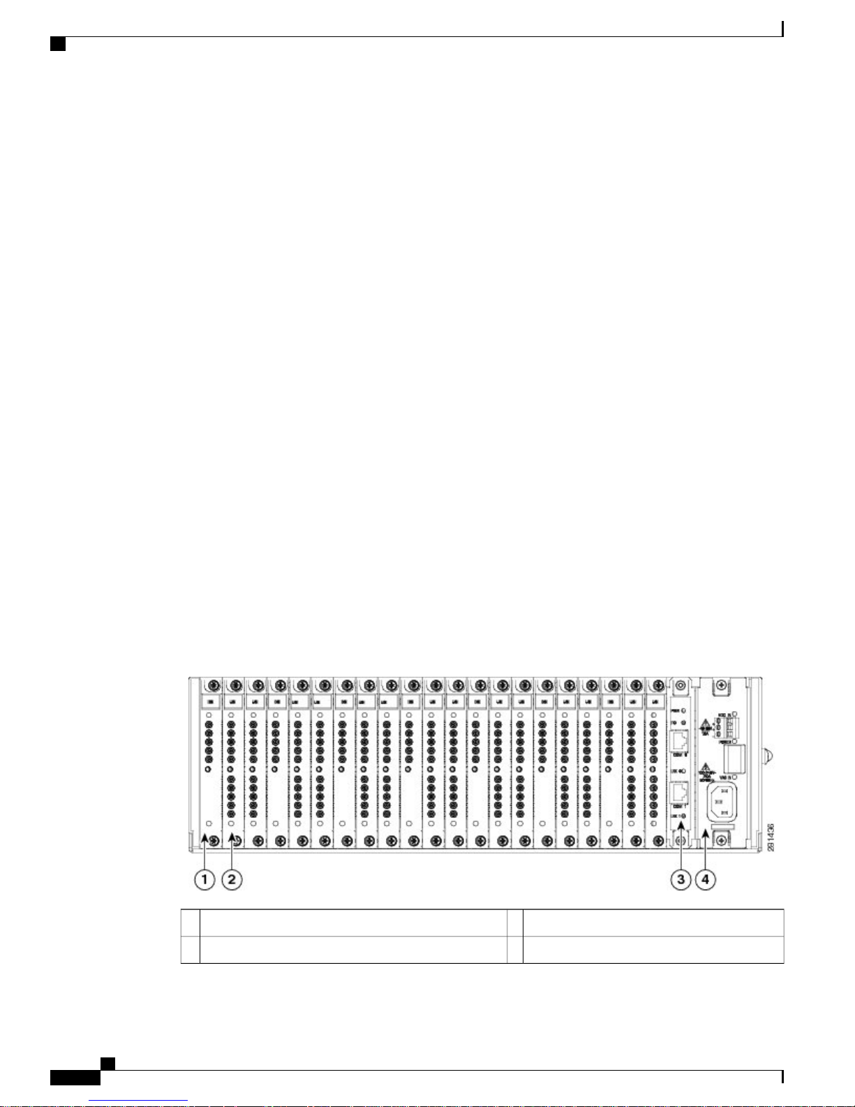
The figures below show the front view (cable plant side) and the rear view (CMTS side) of the
Cisco UBR-RFSW-ADV.
Figure 1: Cisco UBR-RFSW-ADV—Front View (Cable Plant Side)
Cisco uBR Advanced RF Switch Hardware Installation Guide
2 OL-24104-01
Controller card3Downstream interconnect card1
Power supply module4Upstream interconnect card2
Page 3
Introduction
Overview
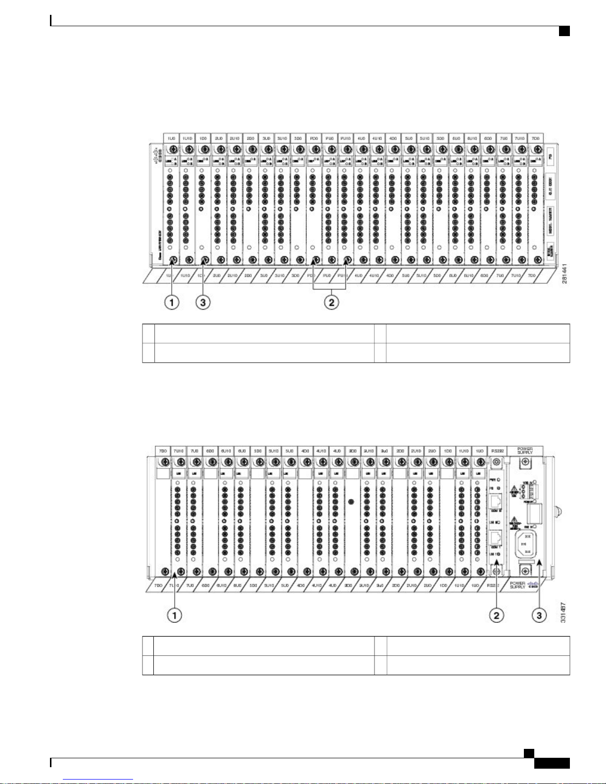
Figure 2: Cisco UBR-RFSW-ADV—Rear View (CMTS Side)
Downstream Switch Card3Upstream Switch Card1
Upstream and Downstream Protect Cards2
—
The figure below shows the front view (cable plant side) of the upstream-only version of the
Cisco UBR-RFSW-ADV.
Figure 3: Upstream-Only Version of Cisco UBR-RFSW-ADV—Front View (Cable Plant Side)
Controller card2
OL-24104-01 3
Power supply module3Upstream interconnect card1
—
Cisco uBR Advanced RF Switch Hardware Installation Guide
Page 4
Overview
Introduction
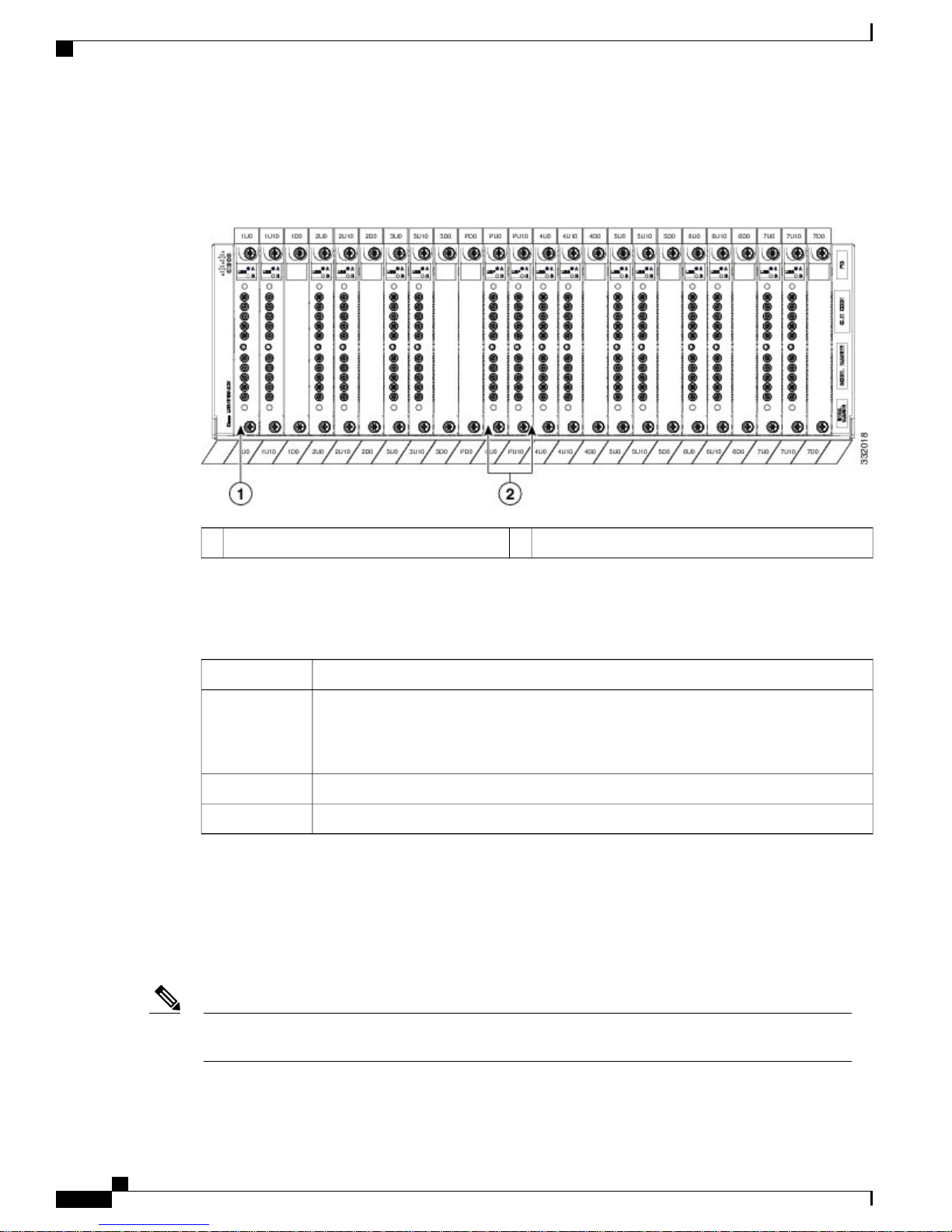
The figure below shows the rear view (CMTS side) of the upstream-only version of the
Cisco UBR-RFSW-ADV.
Figure 4: Upstream-Only Version of Cisco UBR-RFSW-ADV—Rear View (CMTS Side)
Upstream protect cards2Upstream switch card1
The table below lists the Cisco UBR-RFSW-ADV chassis dimensions.
Table 1: Cisco UBR-RFSW-ADV Chassis Dimensions
DimensionUnit
Chassis Depth
17.70 in (44.96 cm)—measured from front connector panel face to rear connector panel
face
19.46 in (49.43 cm)—measured from front connector handle to rear connector handle
17.28 in (43.89 cm)Chassis Width
3 rack unitsChassis Height
Two types of rack-mounting are supported for the Cisco UBR-RFSW-ADV:
Mounting a Single Cisco UBR-RFSW-ADV Above a Cisco uBR10012 Universal Broadband Router
•
Mounting Two Cisco uBR10012 Universal Broadband Routers and Two Cisco UBR-RFSW-ADVs in
•
a Single Rack
Note
For more details on rack-mounting, see Rack-Mounting the Cisco UBR-RFSW-ADV with the Cisco
uBR10012 Router.
For more information about the Cisco UBR-RFSW-ADV product identifiers (PIDs), see Power Requirements.
Cisco uBR Advanced RF Switch Hardware Installation Guide
4 OL-24104-01
Page 5
Introduction
Cisco UBR-RFSW-ADV—Hardware Components Description
Cisco UBR-RFSW-ADV—Hardware Components Description
The Cisco UBR-RFSW-ADV consists of the following hardware components:
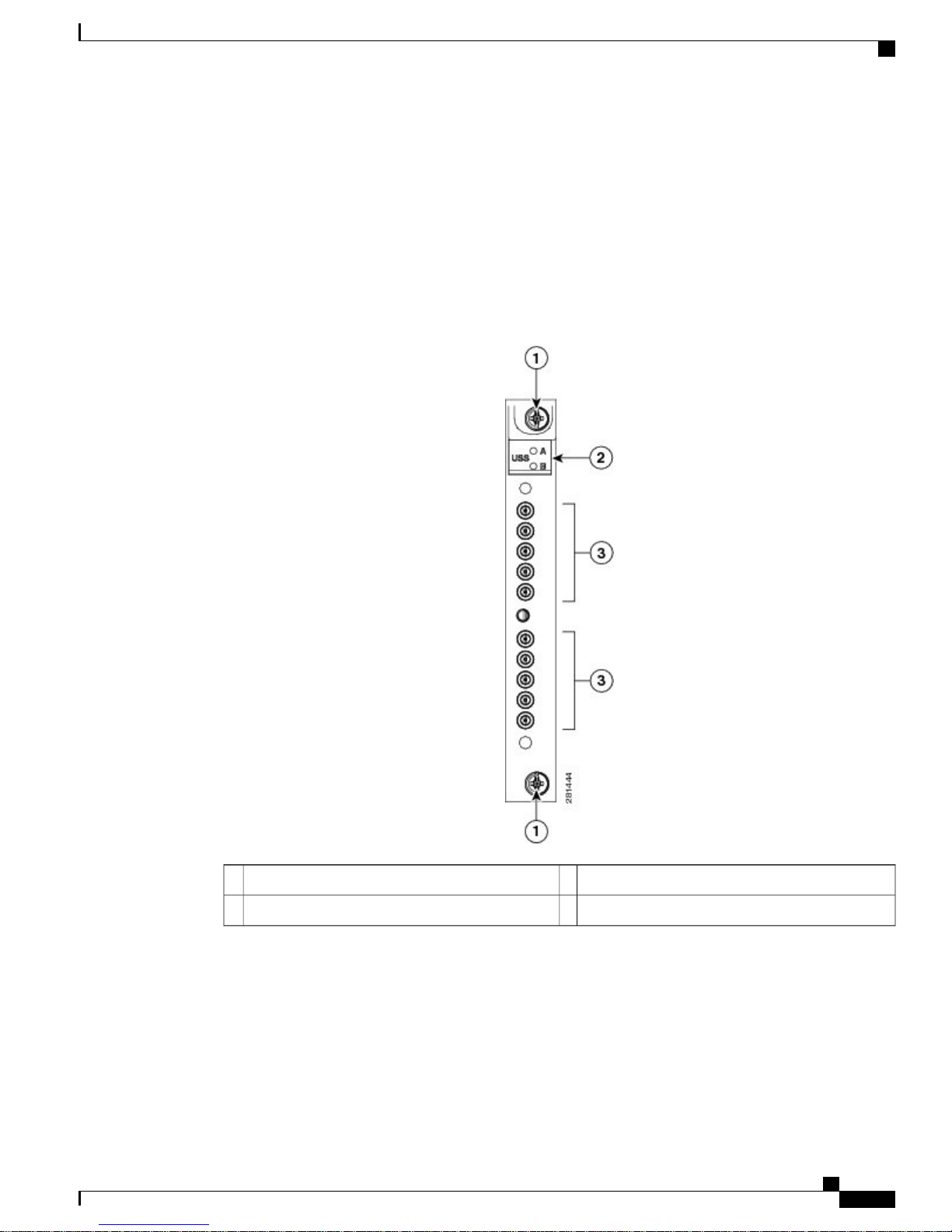
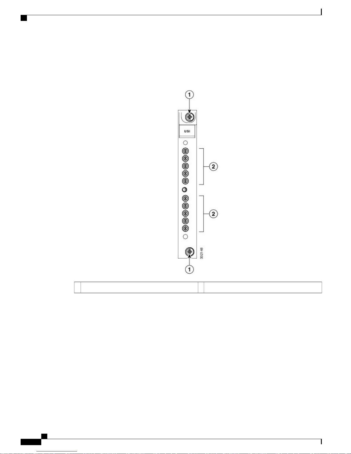
Upstream Switch Cards
Figure 5: Upstream Switch Card Faceplate
LEDs2
On the Cisco uBR10012 router side of the Cisco UBR-RFSW-ADV, there are 14 upstream switch cards.
Two upstream switches are used for each line card on the Cisco uBR10012 router (CMTS side).
For information about the PIDs for the upstream switch card and upstream protect card, see Cisco
UBR-RFSW-ADV Components Part Numbers and Product Identifiers.
OL-24104-01 5
Two sets of five upstream ports3Captive screws1
—
Cisco uBR Advanced RF Switch Hardware Installation Guide
Page 6
Upstream Interconnect Cards
Upstream Interconnect Cards
Figure 6: Upstream Interconnect Card Faceplate
Introduction
On the cable plant side of the Cisco UBR-RFSW-ADV there are 14 upstream interconnect cards.
For information about the PIDs for the upstream interconnect card, see Cisco UBR-RFSW-ADV Components
Part Numbers and Product Identifiers.
Cisco uBR Advanced RF Switch Hardware Installation Guide
6 OL-24104-01
Two sets of five upstream ports2Captive screws1
Page 7

Introduction
Upstream Protect Cards
Figure 7: Upstream Protect Card Faceplate
Upstream Protect Cards
LEDs2
On the Cisco CMTS side of the Cisco UBR-RFSW-ADV there are two upstream protect cards.
For information about the PIDs for the upstream protect card, see Cisco UBR-RFSW-ADV Components Part
Numbers and Product Identifiers.
OL-24104-01 7
Two sets of five upstream ports3Captive screws1
—
Cisco uBR Advanced RF Switch Hardware Installation Guide
Page 8

Downstream Switch Cards
Downstream Switch Cards
Figure 8: Downstream Switch Card Faceplate
Introduction
LEDs2
On the Cisco CMTS side of the Cisco UBR-RFSW-ADV, there are seven downstream switch cards.
For information about the PIDs for the downstream switch card, see Cisco UBR-RFSW-ADV Components
Part Numbers and Product Identifiers.
Cisco uBR Advanced RF Switch Hardware Installation Guide
8 OL-24104-01
Five downstream ports3Captive screws1
—
Page 9

Introduction
Downstream Interconnect Cards
Figure 9: Downstream Interconnect Card Faceplate
Downstream Interconnect Cards
On the cable plant side of the Cisco UBR-RFSW-ADV, there are seven downstream interconnect cards.
For information about the PIDs for the downstream interconnect card, see Cisco UBR-RFSW-ADV Components
Part Numbers and Product Identifiers.
OL-24104-01 9
Five downstream ports2Captive screws1
Cisco uBR Advanced RF Switch Hardware Installation Guide
Page 10

Downstream Protect Cards
Downstream Protect Cards
Figure 10: Downstream Protect Card Faceplate
Introduction
LEDs2
On the Cisco CMTS side of the Cisco UBR-RFSW-ADV there is only one downstream protect card.
For information about the PIDs for the downstream protect card, see Cisco UBR-RFSW-ADV Components
Part Numbers and Product Identifiers.
Cisco uBR Advanced RF Switch Hardware Installation Guide
10 OL-24104-01
Five downstream ports3Captive screws1
—
Page 11

Introduction
Power Supply Module
Figure 11: Power Supply Module on the Cisco UBR-RFSW-ADV
Power Supply Module
The power supply module (PSM) allows either an AC, or DC connection, or both. If both AC and DC are
connected, operation is not affected if either power supply fails.
The panel mount power switch (on/off) disables the output of the PSM. The AC and DC converter stages, if
powered, will remain active.
For information on power supply LEDs, see Power Supply LED Behavior
OL-24104-01 11
AC input plug5Captive screws1
Retainer loop for holding AC power cord6DC input connector2
AC input LED7Power LED3
DC input LED8Power switch (On/Off)4
Cisco uBR Advanced RF Switch Hardware Installation Guide
Page 12

Power Supply Module
Introduction
Caution
Caution
When installing or removing the power supply module, ensure that the Cisco UBR-RFSW-ADV is powered
off and that you have disconnected all power cables.
When inserting or removing the power supply from the Cisco UBR-RFSW-ADV chassis, you must use
a screwdriver to tighten and loosen the captive installation screws.
The table below lists the power requirements for the Cisco UBR-RFSW-ADV.
Table 2: Cisco UBR-RFSW-ADV Power Requirements
RequirementParameter
Power Input DC
Worldwide ranging DC (-40.5 to -72 V: -48 V nominal)
Nominal 23W; maximum 23 W
Power Input AC
Worldwide ranging AC (100 to 240 VAC, 50 to 60 Hz)
Nominal 47W; maximum 105 W
Nominal 70W; maximum 128 WPower Input AC
and DC
Power
Consumption
Maximum (DC): 30 W
Maximum (AC): 30 W
IEC320 connectorAC Input Plug
DC Input
Connection
DC input connection uses a terminal block—DMKDS 2.5, 3- position connector.
Recommended conductor cross-section: 14 AWG
Maximum conductor cross-section: 12 AWG
For information about the PIDs for the PSM, see Cisco UBR-RFSW-ADV Components Part Numbers and
Product Identifiers.
Cisco uBR Advanced RF Switch Hardware Installation Guide
12 OL-24104-01
Page 13
Introduction
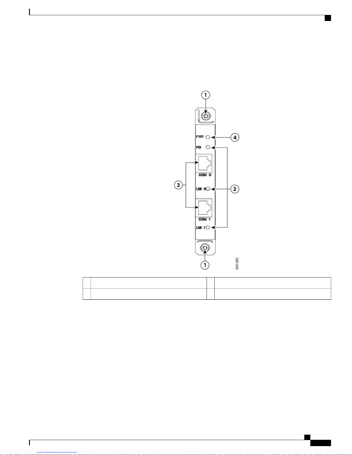
Controller Card
Figure 12: Controller Card Faceplate
Controller Card
The controller card in the Cisco UBR-RFSW-ADV has two RS-232 COM ports—COM 0 and COM 1. COM
0 must be connected to the AUX port of the primary Performance Routing Engine (PRE) on the Cisco
uBR10012 router using an RJ-45 to RJ-45 rollover cable.
COM 1 may be connected to the AUX port of the secondary PRE, for redundancy purposes.
The table below describes the LEDs on the controller card.
OL-24104-01 13
RJ-45 ports3Captive screws1
Power LED4LEDs2
Cisco uBR Advanced RF Switch Hardware Installation Guide
Page 14

Controller Card
Introduction
State DescriptionColor/StateLED
Card is not powered on.OffPower/System
Green (blinking)
Card is either powering on and is in the process of configuring the
system, or the Cisco UBR-RFSW-ADV is in the process of downloading
and reconfiguring the system.
Normal operation.Green
Alarm condition.Amber
System in pass-through mode.OffFailover (FO)
Blue
System has completed a line card failover and is still in the failover
configuration.
Communication link to the Cisco uBR10012 router is not established.OffCOM 0/COM
1
Communication link with the Cisco uBR10012 router is established.Green
The controller card provides the following high-level status information to the PRE:
General health of the Cisco UBR-RFSW-ADV
•
Version information
•
Command history
•
Command status (success or failure)
•
Operational status (active or standby status of the relays)
•
Status of switchover or revertback request sent by the PRE
•
For information about the controller PIDs, see Cisco UBR-RFSW-ADV Components Part Numbers and
Product Identifiers.
Cisco uBR Advanced RF Switch Hardware Installation Guide
14 OL-24104-01
Page 15

Introduction
Rack-Mount Kit
Figure 13: Rack-Mount Kit
Rack-Mount Kit
Rear-mounting (CMTS side) slide bracket2
For information about the PIDs for the rack-mount kit, see Cisco UBR-RFSW-ADV Components Part Numbers
and Product Identifiers.
Cable-Management Bracket
A new cable-management bracket used for securing the cable bundles for easy management and maintenance
is introduced with the Cisco UBR-RFSW-ADV. This cable-management bracket mounts directly to the rack
rails above a Cisco UBR-RFSW-ADV. It uses an additional one rack-unit (RU) of rack space when used
without the cable locking bar and two RUs when the cable locking bar is used.
Rear-mounting (CMTS side) slide3Front-mount (cable plant side) bracket1
—
OL-24104-01 15
Cisco uBR Advanced RF Switch Hardware Installation Guide
Page 16

Interface Overview
Introduction
The figure below shows the Cisco UBR-RFSW-ADV cable-management bracket.
Figure 14: Cisco UBR-RFSW-ADV—Cable-Management Bracket
1
locking bar is inserted
2
bar
For information about the cable-management bracket PID, see Cisco UBR-RFSW-ADV Components Part
Numbers and Product Identifiers.
Interface Overview
This section describes the PRE AUX port interface on the Cisco CMTS router and its impact on the
Cisco UBR-RFSW-ADV.
PRE AUX Port Interface
The PRE AUX port is an RS-232 serial port with an RJ-45 style connector provided on all PRE cards shipped
with the Cisco uBR10012 router. It is available on the primary PRE as well as the secondary PRE. It is located
next to the console port on the PRE. If the AUX port is not used to control the Cisco UBR-RFSW-ADV, it
may be used as an alternate console connection to the PRE.
Cable locking bar3Captive sheetmetal slot into which the tab of the
Cable guides4Captive screw on the cable-management locking
Cisco uBR Advanced RF Switch Hardware Installation Guide
16 OL-24104-01
Page 17

Introduction
PRE AUX Port Interface
The AUX port is used to interface with the Cisco UBR-RFSW-ADV. All commands are executed from the
PRE using this AUX serial interface. A command-control model is used where the PRE serves as a master
and the Cisco UBR-RFSW-ADV as the slave. All Cisco UBR-RFSW-ADV-related control operations and
status collection operations are initiated by the PRE. The PRE sends commands to the Cisco UBR-RFSW-ADV
over the RS-232 cable, using a proprietary protocol. The Cisco UBR-RFSW-ADV then responds with status
information.
OL-24104-01 17
Cisco uBR Advanced RF Switch Hardware Installation Guide
Page 18

PRE AUX Port Interface
Introduction
Cisco uBR Advanced RF Switch Hardware Installation Guide
18 OL-24104-01
 Loading...