

Page 1

Cisco uBR7225VXR Universal Broadband Router Hardware Installation Guide
THE SPECIFICATIONS AND INFORMATION REGARDING THE PRODUCTS IN THIS MANUAL ARE SUBJECT TO
CHANGE WITHOUT NOTICE. ALL STATEMENTS, INFORMATION, AND RECOMMENDATIONS IN THIS
MANUAL ARE BELIEVED TO BE ACCURATE BUT ARE PRESENTED WITHOUT WARRANTY OF ANY KIND,
EXPRESS OR IMPLIED. USERS MUST TAKE FULL RESPONSIBILITY FOR THEIR APPLICATION OF ANY
PRODUCTS.
Americas Headquarters
Cisco Systems, Inc.
170 West Tasman Drive
San Jose, CA 95134-1706
USA
http://www.cisco.com
Tel: 408 526-4000
800 553-NETS (6387)
Fax: 408 527-0883
Text Part Number: OL-17309-02
Page 2

THE SOFTWARE LICENSE AND LIMITED WARRANTY FOR THE ACCOMPANYING PRODUCT ARE SET FORTH IN THE
INFORMATION PACKET THAT SHIPPED WITH THE PRODUCT AND ARE INCORPORATED HEREIN BY THIS REFERENCE. IF YOU
ARE UNABLE TO LOCATE THE SOFTWARE LICENSE OR LIMITED WARRANTY, CONTACT YOUR CISCO REPRESENTATIVE FOR A
COPY.
The following information is for FCC compliance of Class A devices: This equipment has been tested and found to comply with the limits for a Class
A digital device, pursuant to part 15 of the FCC rules. These limits are designed to provide reasonable protection against harmful interference when
the equipment is operated in a commercial environment. This equipment generates, uses, and can radiate radio-frequency energy and, if not installed
and used in accordance with the instruction manual, may cause harmful interference to radio communications. Operation of this equipment in a
residential area is likely to cause harmful interference, in which case users will be required to correct the interference at their own expense.
The following information is for FCC compliance of Class B devices: The equipment described in this manual generates and may radiate
radio-frequency energy. If it is not installed in accordance with Cisco’s installation instructions, it may cause interference with radio and television
reception. This equipment has been tested and found to comply with the limits for a Class B digital device in accordance with the specifications in
part 15 of the FCC rules. These specifications are designed to provide reasonable protection against such interference in a residential installation.
However, there is no guarantee that interference will not occur in a particular installation.
Modifying the equipment without Cisco’s written authorization may result in the equipment no longer complying with FCC requirements for Class
A or Class B digital devices. In that event, your right to use the equipment may be limited by FCC regulations, and you may be required to correct
any interference to radio or television communications at your own expense.
You can determine whether your equipment is causing interference by turning it off. If the interference stops, it was probably caused by the Cisco
equipment or one of its peripheral devices. If the equipment causes interference to radio or television reception, try to correct the interference by
using one or more of the following measures:
• Turn the television or radio antenna until the interference stops.
• Move the equipment to one side or the other of the television or radio.
• Move the equipment farther away from the television or radio.
• Plug the equipment into an outlet that is on a different circuit from the television or radio. (That is, make certain the equipment and the television
or radio are on circuits controlled by different circuit breakers or fuses.)
Modifications to this product not authorized by Cisco Systems, Inc. could void the FCC approval and negate your authority to operate the product.
The Cisco implementation of TCP header compression is an adaptation of a program developed by the University of California, Berkeley (UCB) as
part of UCB’s public domain version of the UNIX operating system. All rights reserved. Copyright © 1981, Regents of the University of California.
NOTWITHSTANDING ANY OTHER WARRANTY HEREIN, ALL DOCUMENT FILES AND SOFTWARE OF THESE SUPPLIERS ARE
PROVIDED “AS IS” WITH ALL FAULTS. CISCO AND THE ABOVE-NAMED SUPPLIERS DISCLAIM ALL WARRANTIES, EXPRESSED
OR IMPLIED, INCLUDING, WITHOUT LIMITATION, THOSE OF MERCHANTABILITY, FITNESS FOR A PARTICULAR PURPOSE AND
NONINFRINGEMENT OR ARISING FROM A COURSE OF DEALING, USAGE, OR TRADE PRACTICE.
IN NO EVENT SHALL CISCO OR ITS SUPPLIERS BE LIABLE FOR ANY INDIRECT, SPECIAL, CONSEQUENTIAL, OR INCIDENTAL
DAMAGES, INCLUDING, WITHOUT LIMITATION, LOST PROFITS OR LOSS OR DAMAGE TO DATA ARISING OUT OF THE USE OR
INABILITY TO USE THIS MANUAL, EVEN IF CISCO OR ITS SUPPLIERS HAVE BEEN ADVISED OF THE POSSIBILITY OF SUCH
DAMAGES.
Cisco and the Cisco logo are trademarks or registered trademarks of Cisco and/or its affiliates in the U.S. and other countries. To view a list of
Cisco trademarks, go to this URL: www.cisco.com/go/trademarks. Third-party trademarks mentioned are the property of their respective owners.
The use of the word partner does not imply a partnership relationship between Cisco and any other company. (1110R)
Cisco uBR7225VXR Universal Broadband Router Hardware Installation Guide
Copyright © 2008-2009, 2012 Cisco Systems, Inc.
All rights reserved.
Page 3

CONTENTS
Document Revision History ix
Document Objectives ix
Audience x
Document Organization x
Document Conventions xi
Warning Definition xii
Obtaining Documentation and Submitting a Service Request xii
CHAPTER
1 Cisco uBR7225VXR Overview 1-1
Cisco uBR7225VXR Universal Broadband Router 1-1
Cisco uBR7225VXR Router Chassis 1-3
Cisco uBR7225VXR Network Interface Overview 1-4
Card Slot and Logical Interface Numbering 1-4
MAC-Layer Address 1-5
Supported System Configurations Overview 1-6
Basic Internet Access Services 1-6
VPN Services 1-8
IP Telephony Services 1-8
Telco Return 1-9
Hardware Component Descriptions 1-10
Network Processing Engine 1-10
NPE Comparisons 1-11
Cisco Cable Interface Line Cards 1-12
Power Supplies 1-13
Fan Trays 1-14
Cisco uBR7225VXR Chassis 1-17
Subchassis and Midplane 1-17
Cisco uBR7225VXR Subchassis 1-17
CompactFlash Disk 1-18
CHAPTER
OL-17309-02
2 Preparing the Cisco uBR7225VXR Router for Installation 2-1
Safety Recommendations 2-1
Lifting the Cisco uBR7225VXR Router Safely 2-2
Safety with Electricity 2-3
Cisco uBR7225VXR Universal Broadband Router Hardware Installation Guide
iii
Page 4

Contents
Preventing Electrostatic Discharge Damage 2-4
Site Requirements 2-5
AC Power 2-5
Site Environment 2-5
Site Configuration: Maintaining Normal Operation 2-6
General Precautions 2-6
Power Considerations 2-7
Required Network Information 2-7
Before You Begin 2-7
Installation Tools 2-8
Rack-Mount and Cable-Management Kit 2-8
Equipment Required to Verify Your Plant’s RF Setup 2-9
Shipping Container Contents 2-9
Verifying the Shipping Container Contents 2-9
Provisioning the Cable Headend 2-10
Two-Way Data and VoIP 2-10
Headend Certification 2-11
Diplex Filters 2-11
Receivers 2-11
DHCP, DNS, TFTP, and TD Servers 2-12
Telco Return 2-12
Dial-Up/Remote Access Servers 2-12
RADIUS Dial Security Servers 2-12
Authentication, Authorization, and Accounting Servers 2-13
VoIP Gateways and Gatekeepers 2-13
VoIP SGCP Pass-Through 2-13
Headend Wiring 2-14
Interference Considerations 2-14
Distance Limitations and Interface Specifications 2-14
Equipment Racks 2-15
Site Preparation Checklist 2-17
Component Checklists 2-18
CHAPTER
iv
3 Installing the Cisco uBR7225VXR Router 3-1
Cisco uBR7225VXR Router Installation Checklist 3-1
Cisco uBR7225VXR Router Chassis Rack-Mounting Options 3-2
Cable-Management Bracket Requirements 3-5
Installing the Brackets on the Chassis 3-7
Cisco uBR7225VXR Universal Broadband Router Hardware Installation Guide
OL-17309-02
Page 5

Installing Rack-Mount Brackets on the Rear of the Chassis 3-7
Installing Rack-Mount Brackets on the Front of the Chassis 3-8
Installing Rack-Mount Brackets in the Middle of the Chassis 3-9
Installing the Chassis in the Rack 3-10
Installing the Chassis in a Workbench or Tabletop Environment 3-12
Installing the Cable-Management Bracket on a Cisco uBR7225VXR Router in a Workbench or
Tabletop Environment 3-13
Cabling 3-13
Connecting Cable Interface Line Card Cables 3-14
Console and Auxiliary Port Connection Equipment 3-14
Console Port Signals 3-15
Auxiliary Port Signals 3-15
Protective Grounding 3-16
Connecting Power 3-16
Connecting to the AC-Input Power Supply 3-17
Contents
CHAPTER
Powering On the Cisco uBR7225VXR Router 3-18
Configuring the Interfaces 3-19
4 Connecting the Cisco uBR7225VXR Router to the Cable Headend 4-1
Two-Way Data Headend Architecture 4-2
One-Way Data Headend Architecture 4-3
RF and Digital Data Overview 4-3
Connecting and Configuring the Downstream 4-4
Installing and Configuring the Upconverter 4-4
Measuring the Downstream RF Signal 4-4
Measuring the Downstream RF Signal Using the Channel Power Option on a Spectrum Analyzer 4-5
Measuring the Downstream IF Signal at the Cisco uBR7225VXR Router 4-5
Measuring the Downstream RF Signal at the Upconverter Output 4-7
Measuring the Downstream RF Signal Using CATV Mode on a Spectrum Analyzer 4-11
Measuring the Downstream IF Signal at the Cisco uBR7225VXR Router Using CATV Mode 4-11
Measuring the Downstream RF Signal at the Upconverter Output Using CATV Mode 4-14
Connecting and Configuring the Upstream 4-18
Connecting the Upstream to the Optical Receiver 4-18
Testing the Upstream Configuration 4-19
OL-17309-02
Measuring the Upstream RF Signal 4-22
Measuring the Upstream RF Signal Using a Spectrum Analyzer 4-22
Analyzing the Upstream RF Signal 4-25
Using the Zero-Span Method with Adjacent Upstream Channels 4-28
Cisco uBR7225VXR Universal Broadband Router Hardware Installation Guide
v
Page 6

Contents
Measuring the RF Signal at the Forward Test Point on a Laser Transmitter 4-37
Configuring the Digital Signal 4-40
CHAPTER
CHAPTER
5 Maintaining the Cisco uBR7225VXR Router 5-1
Online Insertion and Removal 5-1
Environmental Monitoring and Reporting Functions 5-2
Environmental Monitoring 5-2
Reporting Functions 5-3
Fan Failures 5-6
6 Troubleshooting 6-1
Overview 6-1
Providing Information 6-1
Problem Solving with Subsystems 6-2
Identifying Startup Problems 6-3
Power Subsystem 6-4
Cooling Subsystem 6-4
Processor Subsystem 6-5
Troubleshooting the Network Processing Engine 6-5
Troubleshooting Cable Interface Line Cards 6-6
Other Troubleshooting Information Websites 6-7
APPENDIX
APPENDIX
Verifying the Downstream Signal 6-7
A Cisco uBR7225VXR Router Specifications A-1
Cisco uBR7225VXR Physical and System Specifications A-1
B RF Specifications B-1
DOCSIS 1.0 Transmission Characteristics B-2
Downstream RF Channel Transmission Characteristics B-2
Upstream RF Channel Transmission Characteristics B-3
DOCSIS 1.1 Transmission Characteristics B-4
Downstream RF Channel Transmission Characteristics B-4
Upstream RF Channel Transmission Characteristics B-5
EuroDOCSIS Transmission Characteristics B-5
Downstream RF Channel Transmission Characteristics B-6
Upstream RF Channel Transmission Characteristics B-7
Electrical Input and Output B-8
vi
Cisco uBR7225VXR Universal Broadband Router Hardware Installation Guide
OL-17309-02
Page 7

Contents
APPENDIX
APPENDIX
APPENDIX
C Cable Specifications C-1
Coaxial Cables C-1
Console and Auxiliary Port Cables and Pinouts C-2
Identifying an RJ-45 Rollover Cable C-2
Console Port Cables and Pinouts C-3
Auxiliary Port Cables and Pinouts C-4
Fast Ethernet Port Cables and Pinouts C-4
Identifying an RJ-45 Crossover Cable C-4
Identifying an RJ-45 Straight-Through Cable C-5
Fiber-Optic Cables and Connectors C-6
D Industry-Standard Wiring Plans D-1
About Wiring Standards D-1
TIA/EIA Standards Information D-2
Optical Fiber Color Codes D-2
Telephone Wire Color Codes D-3
E Frequency Allocation Tables E-1
APPENDIX
APPENDIX
G
LOSSARY
I
NDEX
Standards Comparisons E-2
NTSC Cable Television Channels and Relative Frequencies E-3
NTSC (M) Cable Television Frequencies for Japan E-8
PAL/SECAM Cable Television Channels and Relative Frequencies E-10
F Manufacturers for Headend Provisioning Requirements F-1
North American Channel Plans F-1
European Channel Plans F-3
G Site Log G-1
OL-17309-02
Cisco uBR7225VXR Universal Broadband Router Hardware Installation Guide
vii
Page 8

Contents
viii
Cisco uBR7225VXR Universal Broadband Router Hardware Installation Guide
OL-17309-02
Page 9

Preface
This preface describes the objectives, intended audience, and organization of this document and explains
how to find additional information on related products and services.
This preface contains the following sections:
• Document Revision History, page ix
• Document Objectives, page ix
• Audience, page x
• Document Organization, page x
• Document Conventions, page xi
• Obtaining Documentation and Submitting a Service Request, page xii
Document Revision History
The Document Revision History table below records technical changes to this document.
Revision Date Change Summary
OL-17309-01 December 15, 2008 Original publication.
OL-17309-02 August 2012 Added information about the new 540 W AC-input power
Document Objectives
This guide provides hardware installation instructions for the Cisco uBR7225VXR universal broadband
router.
The guide contains procedures to unpack, install, and connect the Cisco uBR7225VXR router hardware
that enables your cable television (CATV) headend or distribution hub to support digital data and
Voice-over-IP (VoIP) services. The guide includes procedures to characterize your cable plant to ensure
that data services are reliably supported over the cable infrastructure.
supply.
OL-17309-02
Cisco uBR7225VXR Universal Broadband Router Hardware Installation Guide
ix
Page 10

Audience
Preface
This guide is intended for cable system installers and technicians who physically install and connect the
Cisco uBR7225VXR universal broadband router and associated equipment at the cable headend or
distribution hub. Cable system installers and technicians should be familiar with their cable plant base
operating parameters and service offerings.
The guide provides limited configuration information. After following applicable procedures in this
guide, refer to the “Obtaining Documentation and Submitting a Service Request” section on page xii for
related Cisco publications that more completely address configuration.
Warning
Only trained and qualified personnel should be allowed to install, replace, or service this equipment.
Statement 1030
Document Organization
This hardware installation guide is organized into the following chapters and appendixes:
Chapter Title Description
Chapter 1, “Cisco uBR7225VXR
Overview”
Chapter 2, “Preparing the
Cisco uBR7225VXR Router for
Installation”
Chapter 3, “Installing the
Cisco uBR7225VXR Router”
Chapter 4, “Connecting the
Cisco uBR7225VXR Router to the
Cable Headend”
Chapter 5, “Maintaining the
Cisco uBR7225VXR Router”
Chapter 6, “Troubleshooting” Troubleshooting hardware installations.
Appendix A, “Cisco uBR7225VXR
Router Specifications”
Appendix B, “RF Specifications” Recommended RF settings at the headend for both Data-over-Cable Service
Appendix C, “Cable Specifications” Cable and cable pinout information for the Cisco uBR7225VXR router.
Appendix D, “Industry-Standard Wiring
Plans”
Appendix E, “Frequency Allocation
Tables ”
About Cisco uBR7225VXR chassis and components.
Safety considerations, tools, and other equipment required to prepare your site.
Installing the chassis and connecting the power and network interface cables.
Connecting the Cisco uBR7225VXR router to a hybrid fiber-coaxial (HFC)
network and configuring and measuring downstream and upstream portions of the
HFC network.
Basic hardware maintenance instructions.
System specifications.
Interface Specifications (DOCSIS) and EuroDOCSIS networks.
The telephone industry color-code schemes for 25-pair wires including the pin
numbers, optical fibers, and small wire pairs.
Information on the National Television System Committee (NTSC) frequency
map for 6-MHz channel bands and the Phase Alternating Line (PAL) and
SEquential Couleur Avec Memoire (SECAM) frequency map for 8-MHz channel
bands.
Cisco uBR7225VXR Universal Broadband Router Hardware Installation Guide
x
OL-17309-02
Page 11

Preface
Appendix F, “Manufacturers for Headend
Provisioning Requirements”
Manufacturers and websites required to prepare and provision a North American
or a European cable headend to support digital data.
Appendix G, “Site Log” Example of a cable headend site log—Use to keep a historical record of actions
relevant to the Cisco uBR7225VXR router installation, operations, and
maintenance.
Document Conventions
This publication uses the following conventions:
• The symbol ^ represents the key labeled Control. For example, the key combination ^z means hold
down the Control key while you press the z key.
Command descriptions use these conventions:
• Examples that contain system prompts denote interactive sessions, indicating the commands that
you should enter at the prompt. The system prompt indicates the current level of the EXEC
command interpreter. For example, the prompt
and the prompt
Router# indicates that you should be at the privileged level.
Access to the privileged level usually requires a password. For additional information, refer to the
related software configuration and reference documentation listed in the Cisco uBR7200 Series
Software Configuration Guide at the following URL:
Router> indicates that you should be at the user level,
http://www.cisco.com/en/US/docs/cable/cmts/ubr7200/configuration/guide/cr72scg.html
• Commands and keywords are in boldface font.
• Arguments for which you supply values are in italic font.
• Elements in square brackets ([ ]) are optional.
• Alternative but required keywords are grouped in braces ({ }) and separated by vertical bars (|).
Examples use these conventions:
• Terminal sessions and sample console screen displays are in screen font.
• Information you enter is in boldface screen font.
• Nonprinting characters, such as passwords, are in angle brackets (< >).
• Default responses to system prompts are in square brackets ([ ]).
• Exclamation points (!) at the beginning of a line indicate a comment line.
Caution Means reader be careful. You are capable of doing something that might result in equipment damage or
loss of data.
Note Means reader take note. Notes contain helpful suggestions or references to materials not contained in
this manual.
OL-17309-02
Cisco uBR7225VXR Universal Broadband Router Hardware Installation Guide
xi
Page 12

Timesaver Means the described action saves time. You can save time by performing the action described in the
paragraph.
Tip Means the following information might help you solve a problem.
For all warning translations, refer to the Regulatory Compliance and Safety Information for Cisco
uBR7200 Series Universal Broadband Routers at the following URL:
http://www.cisco.com/en/US/docs/cable/cmts/ubr7200/regulatory/compliance/ub72rcsi.html
Warning Definition
Preface
Warning
IMPORTANT SAFETY INSTRUCTIONS
This warning symbol means danger. You are in a situation that could cause bodily injury. Before you
work on any equipment, be aware of the hazards involved with electrical circuitry and be familiar
with standard practices for preventing accidents. Use the statement number provided at the end of
each warning to locate its translation in the translated safety warnings that accompanied this device.
Statement 1071
SAVE THESE INSTRUCTIONS
Obtaining Documentation and Submitting a Service Request
For information on obtaining documentation, submitting a service request, and gathering additional
information, see the monthly What’s New in Cisco Product Documentation, which also lists all new and
revised Cisco technical documentation, at:
http://www.cisco.com/en/US/docs/general/whatsnew/whatsnew.html
Subscribe to the What’s New in Cisco Product Documentation as a Really Simple Syndication (RSS)
feed and set content to be delivered directly to your desktop using a reader application. The RSS feeds
are a free service and Cisco currently supports RSS version 2.0.
xii
Cisco uBR7225VXR Universal Broadband Router Hardware Installation Guide
OL-17309-02
Page 13

CHAP T E R
Cisco uBR7225VXR Overview
This chapter describes the Cisco uBR7225VXR universal broadband router and contains the following
sections:
• Cisco uBR7225VXR Universal Broadband Router, page 1-1
• Cisco uBR7225VXR Network Interface Overview, page 1-4
• Supported System Configurations Overview, page 1-6
• Hardware Component Descriptions, page 1-10
Cisco uBR7225VXR Universal Broadband Router
The Cisco uBR7200 series universal broadband routers, part of the Cisco Cable Modem Termination
System (CMTS) solution, allows high-speed data services to be packaged similar to basic cable
television service or video fare.
1
The router is based on Data-over-Cable Service Interface Specifications (DOCSIS) and supports data
and packetized voice connectivity over a bidirectional cable television and IP backbone network. The
Cisco uBR7200 series universal broadband routers typically concentrates traffic from DOCSIS- or
EuroDOCSIS-based cable interfaces and cable modems (or set-top boxes with integrated DOCSIS or
EuroDOCSIS cable modems) on the cable television network and presents that traffic to local and remote
IP hosts. For cable plants not fully upgraded to support two-way cable transmission, the router works in
conjunction with dial-up access products to support upstream traffic from DOCSIS-based cable
interfaces connected to the Public Switched Telephone Network (PSTN). The router supports both
6-MHz North American channel plans using ITU-T J.83 Annex B operation and 8-MHz Phase
Alternating Line (PAL) and SEquential Couleur Avec Memoire (SECAM) channel plans using ITU-T
J.83 Annex A operation.
The Cisco uBR7200 series universal broadband routers contains some or all of the following:
• Cable interface line cards that interface to the cable television network. The Cisco uBR7225VXR
card set includes varying upstream-to-downstream interface ratios with differing bandwidth and
modulation schemes supported, as well as the capability to dynamically perform complex spectrum
management and operate in a 6-MHz or 8-MHz channel width environment.
See the “Cisco Cable Interface Line Cards” section on page 1-12.
• One network processing engine (NPE) that performs system management functions for the chassis.
See the “Network Processing Engine” section on page 1-10.
• The Cisco uBR7225VXR router supports an optional redundant power supply. See the “Power
Supplies” section on page 1-13.
OL-17309-02
Cisco uBR7225VXR Universal Broadband Router Hardware Installation Guide
1-1
Page 14

Cisco uBR7225VXR Universal Broadband Router
• A midplane that serves as the interconnect between the cable interface line cards and the other
components of the system. See the “Subchassis and Midplane” section on page 1-17.
• A fan tray, enclosing internal fans that draw cooling air into the chassis to maintain an acceptable
operating temperature. See the “Fan Trays” section on page 1-14.
The cable interface cards, NPE, and power supplies slide into their respective chassis slots and connect
directly to the router midplane. There are no internal cables to connect. The midplane distributes power
from the power supplies to the cable interface cards, fan tray, and NPE.
The Cisco uBR7225VXR universal broadband router may be installed on a tabletop or rack-mounted. A
rack-mount kit ships with each router. The rack-mount kit includes the hardware needed to mount the
router in a standard 19-inch equipment rack or telco-type rack.
The Cisco uBR7200 series universal broadband routers supports:
• Environmental monitoring and reporting functions to resolve adverse environmental conditions
before loss of operation.
• Online insertion and removal (OIR), allowing key system components to be added or removed
without powering off the chassis.
Chapter 1 Cisco uBR7225VXR Overview
Caution You can remove and replace a cable interface line card with the same type of component without
interrupting the rest of the system or having to reconfigure the system. However, to replace a
cable interface line card with a different type of card (for example, hot swapping from a
Cisco uBR-MC16U cable interface line card to a Cisco uBR-MC28U cable interface line card), you must
copy your startup configuration to your running configuration on the Cisco uBR7225VXR router to
enable the interfaces on the new cable interface line card.
Caution The NPE does not support OIR. You must power down the chassis before removing the NPE.
Note For specific instructions to install, remove, or replace system components, refer to the documentation at
the following URL:
http://www.cisco.com/en/US/products/hw/cable/ps2217/tsd_products_support_series_home.html
1-2
Cisco uBR7225VXR Universal Broadband Router Hardware Installation Guide
OL-17309-02
Page 15
Chapter 1 Cisco uBR7225VXR Overview
270489
uBR7225-VXR
US2
US4
US5
US6
US7
US1
US0
US3
US2
US4
US5
US1
US0
US3
uBR - MC28U
uBR - MC16U
DS0-RF
DS1
-RF
DS0
-RF
S
L
O
T
1
S
L
O
T
2
1
2
Cisco uBR7225VXR Router Chassis
The Cisco uBR7225VXR router chassis has:
• Two slots for cable interface cards
• One slot for a network processing engine
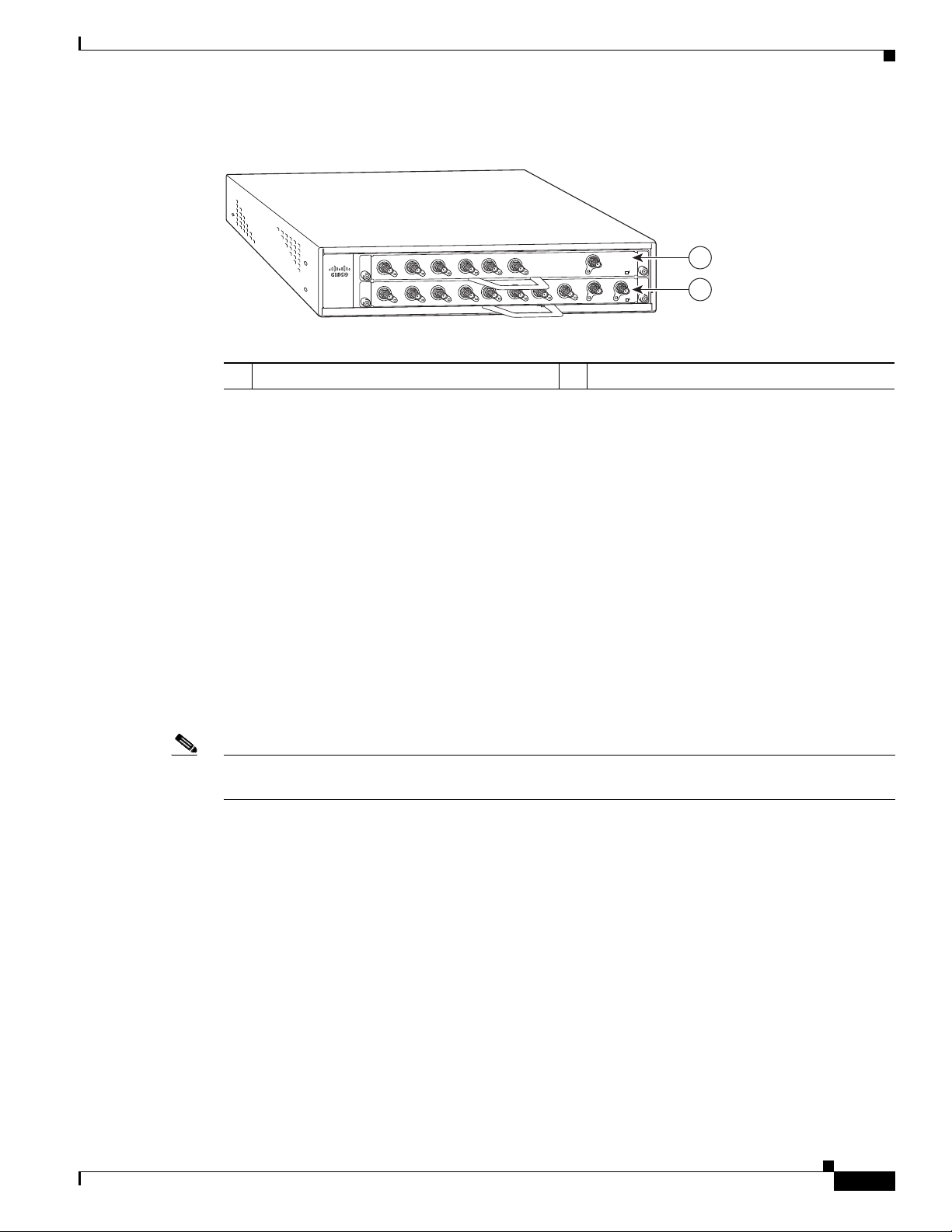
The front of the Cisco uBR7225VXR chassis provides access to two cable interface line cards. See
Figure 1-1.
The rear of the Cisco uBR7225VXR provides access to the network processing engine and up to two
power supplies. See Figure 1-2.
A fully configured Cisco uBR7225VXR router can operate with only one installed power supply;
however, a second, optional power supply of the same type provides hot-swappable, load-sharing, and
redundant power. In a chassis using two power supplies, if one power supply fails or is removed, the
redundant power supply immediately takes over the router’s power requirements and maintains normal
operation without interruption.
The power supply has the router’s main power switch and an AC-input power receptacle. Mounting holes
for a ground lug are located on the far right side on the rear of the chassis, to provide a chassis ground
connection for ESD-preventive equipment. See Figure 3-13 on page 3-16.
Cisco uBR7225VXR Universal Broadband Router
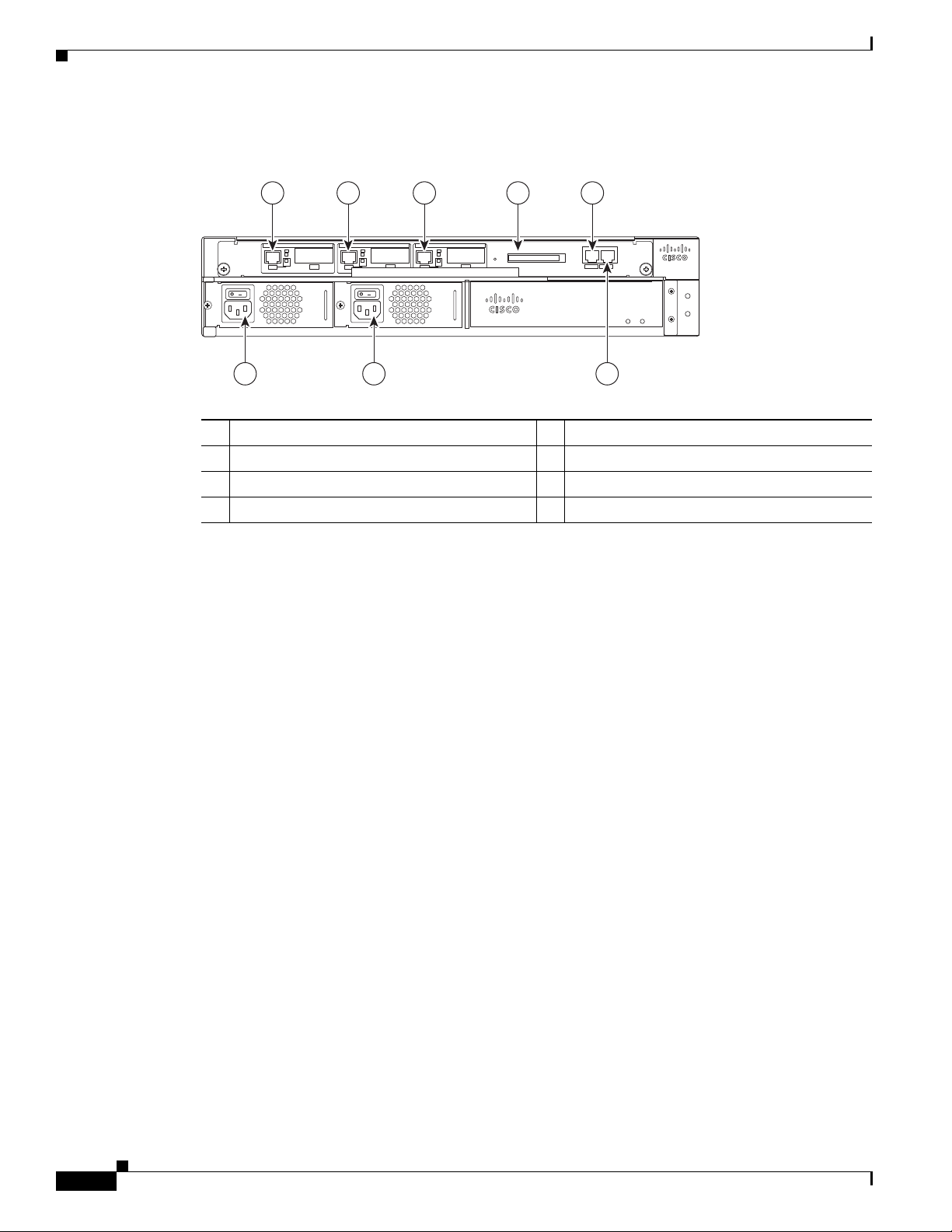
Note Figure 1-2 shows the rear of a Cisco uBR7225VXR router configured with two 300W AC-input power
supplies.
Caution If you are using two power supplies, make sure that each one is plugged into a separate branch circuit.
A fully loaded router, with two installed power supplies (300 W) and all chassis slots filled, weighs
approximately 48 pounds (21.8 kg). For clearance requirements and rack-mount installation
considerations, refer to the “Site Environment” section on page 2-5.
Figure 1-1 Cisco uBR7225VXR Router—Front View
OL-17309-02
Cable interface line card slot 1
1
Cisco uBR7225VXR Universal Broadband Router Hardware Installation Guide
Cable interface line card slot 2
2
1-3
Page 16
Cisco uBR7225VXR Network Interface Overview
Figure 1-2 Cisco uBR7225VXR Router—Rear View
1 2 3 4 5
8 7 6
Chapter 1 Cisco uBR7225VXR Overview
uBR7225-VXR
uBR7225-VXR
270490
Gigabit Ethernet 0/1
1
Gigabit Ethernet 0/2
2
Gigabit Ethernet 0/3
3
CompactFlash Disk slot
4
Console port
5
Auxiliary port
6
AC-input power supply 2
7
AC-input power supply 1
8
Cisco uBR7225VXR Network Interface Overview
This section provides a functional overview of the network interfaces available on the
Cisco uBR7225VXR universal broadband router, cable interface line card slot and logical interface
numbering, as well as the MAC address assignments for cable interface line card interfaces.
Card Slot and Logical Interface Numbering
In the Cisco uBR7200 series universal broadband routers, the slot number is the chassis slot in which a
cable interface card is installed.
Cable interface line card slots maintain the same slot number regardless of whether other cable interface
line cards are installed or removed. However, when you move a cable interface line card to a different
slot, the logical interface number changes to reflect the new slot number.
The MAC-layer or hardware address is a standardized data-link layer address that is required for certain
network interface types. These addresses are specific and unique to each port. The Cisco uBR7225VXR
uses a specific method to assign and control the MAC-layer addresses of its port adapters. For a
description of the MAC-layer address, refer to the “MAC-Layer Address” section on page 1-5.
1-4
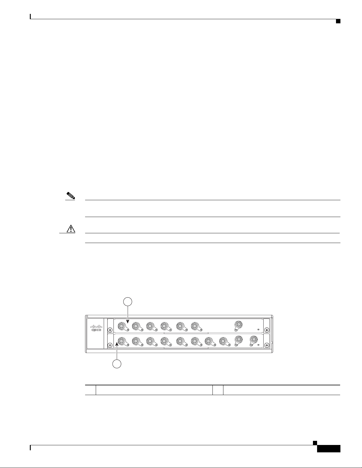
The two cable interface line cards in the Cisco uBR7225VXR router provide the connection between the
router’s two PCI buses (mb1 and mb2) and external networks. See Figure 1-3.
Cisco uBR7225VXR Universal Broadband Router Hardware Installation Guide
OL-17309-02
Page 17
Chapter 1 Cisco uBR7225VXR Overview
Figure 1-3 Cisco uBR7255VXR Chassis and Cable Interface Line Cards
Cisco uBR7225VXR Network Interface Overview
D
S
E18U
-
1
0
US
R
X
5-V
2
2
7
uBR
0
S
U
S2
U
US
2
1
US
US
4
S5
U
US
US3
5
4
3
S
US
U
US
uBR
0
-RF
D
E
L
B
A
N
E
D
D
S1
6
US
S0
uBR - E28U
7
US
-
-RF
R
F
D
E
L
B
A
N
E
1
2
270493
Cable interface line card slot 1
1
MAC-Layer Address
All LAN interfaces (ports) require unique MAC-layer addresses, also known as hardware addresses.
Typically, the MAC address of an interface is stored on a memory component that resides directly on the
interface circuitry; however, the OIR feature requires a different method. For a description of OIR, refer
to the “Online Insertion and Removal” section on page 5-1.
The OIR feature allows you to remove a cable interface line card and replace it with another identically
configured one. If the new cable interface line card matches the cable interface line card you removed,
the system immediately brings it online. In order to allow OIR, an address allocator with a unique MAC
address is stored in EPROM on the Cisco uBR7225VXR universal broadband router midplane. Each
address is reserved for a specific slot in the router regardless of whether a cable interface line card
resides in that slot.
The MAC addresses are assigned to the slots in sequence. This address scheme allows you to remove
cable interface cards and insert them into other universal broadband routers without causing the MAC
addresses to move around the network or be assigned to multiple devices.
Note Storing the MAC addresses for every slot in one central location means that the addresses stay with the
memory device on which they are stored.
Cable interface line card slot 2
2
OL-17309-02
For information on the commands used to configure your Cisco uBR7225VXR router, refer to the Cisco
IOS Configuration Fundamentals Configuration Guide at the following URL:
http://www.cisco.com/en/US/docs/ios/fundamentals/configuration/guide/12_4/cf_12_4_book.html
Also refer to the Cisco IOS Configuration Fundamentals Command Reference at the following URL:
http://www.cisco.com/en/US/docs/ios/fundamentals/command/reference/cf_book.html
Cisco uBR7225VXR Universal Broadband Router Hardware Installation Guide
1-5
Page 18

Supported System Configurations Overview
Supported System Configurations Overview
The Cisco uBR7200 series universal broadband routers is installed at a cable television headend or a
distribution hub. Related networking and RF equipment, servers, and other host computers are installed,
along with the Cisco uBR7225VXR router, to support digital data transmission.
To deliver data and VoIP services over the cable television system, TV channels are allocated to carry
digital data. Data is modulated downstream on:
• 6-MHz channels in the 88 to 860 MHz range, using North American channel plans through
Cisco cable interface line cards installed in the chassis. For bidirectional cable plants, a portion of
the 5 to 42 MHz range is used for upstream data transmission. For one-way cable plants or cable
segments yet to be upgraded, DOCSIS-based cable interfaces configured for telco return are also
supported.
• 8-MHz channels in the 108 to 862 MHz range using PAL/SECAM channel plans through
Cisco cable interface line cards installed in the chassis. For bidirectional cable plants, a portion of
the spectrum in the 5 to 65 MHz range is used for upstream data transmission.
• 6-MHz channels in the 70 to 860 MHz range, using J-DOCSIS channel operation (extensions for
Japan and select regions) through Cisco cable interface line cards installed in the chassis. For
bidirectional cable plants, a portion of the 5 to 55 MHz range is used for upstream data transmission.
The following sections illustrate the supported configurations including:
Chapter 1 Cisco uBR7225VXR Overview
• Basic Internet access services
• Virtual private network (VPN) services
• IP telephony services
• Telco return
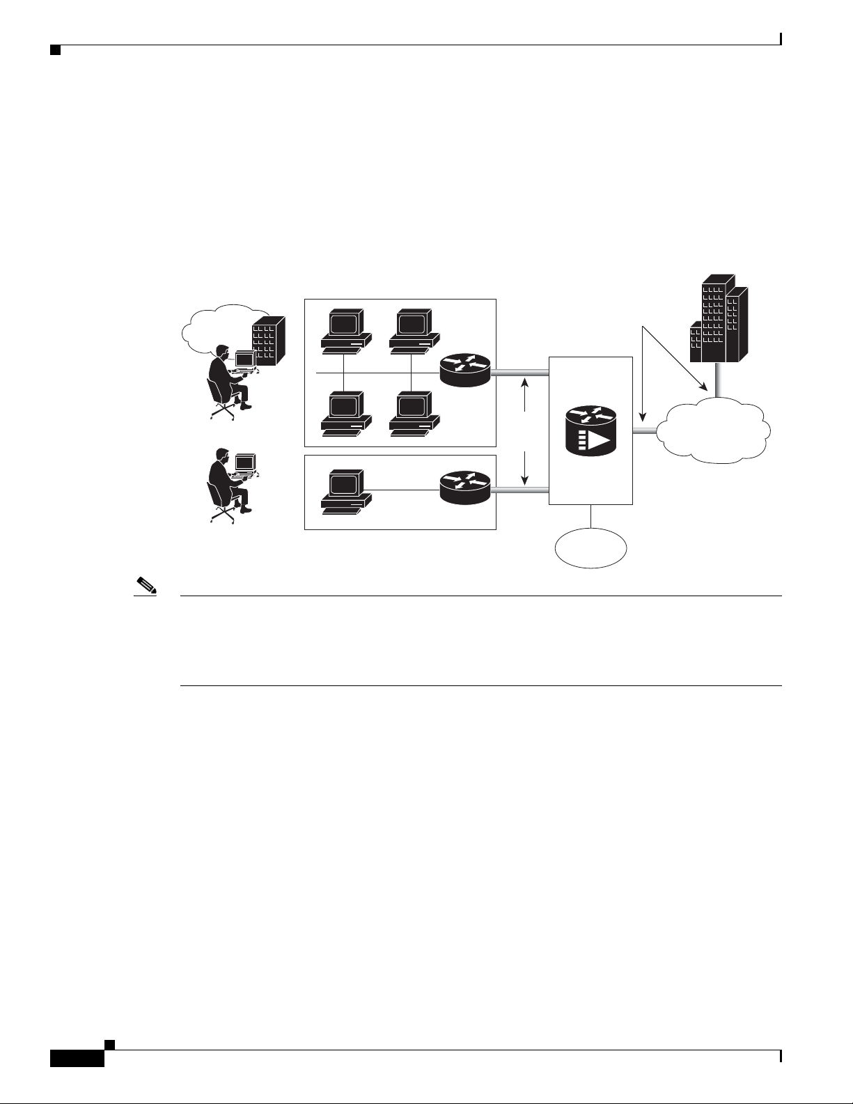
Basic Internet Access Services
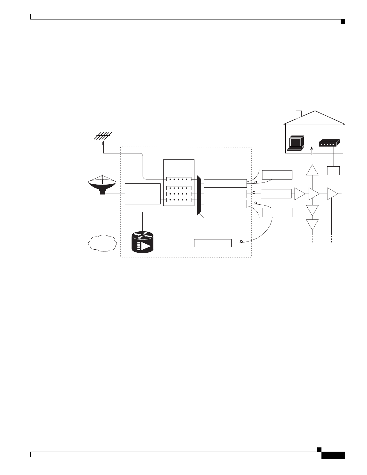
A Cisco uBR7225VXR universal broadband router is installed at the headend or distribution hub. The
Cisco uBR7225VXR downstream cable interface line cards, with onboard upconvertor, translate the
downstream signals to RF for broadcast. The Cisco uBR7225VXR router enables you to transmit
downstream data in both the 6-MHz North American or Japanese and the 8-MHz European channel
environments using the appropriate model of the cable interface line card.
Receivers, scramblers, and descramblers process the television signals to encode or decode signals as
needed for broadcast. Modulators format the analog television and digital signals while upconverters
change the carrier frequency of a modulated signal to a specified frequency. The analog TV channels and
digitally modulated carriers then pass through the RF combiner.
The signals are broadcast from the headend through optical transmitters typically to fiber nodes in the
network. Amplifiers, coaxial cable, and taps carry the signals to the subscriber premises. Signals are
processed as follows:
• Set-top boxes (STBs), televisions, or VCRs receive analog and digital data signals.
• DOCSIS-based cable interfaces and STBs connected to customer premises equipment (CPE) receive
digital data signals:
1-6
–
Two-way cable interfaces transmit RF signals back through amplifiers to optical fiber receivers
at the headend. These receivers pass the upstream signal to the upstream ports on the
Cisco uBR7225VXR router for processing.
Cisco uBR7225VXR Universal Broadband Router Hardware Installation Guide
OL-17309-02
Page 19
Chapter 1 Cisco uBR7225VXR Overview
Over the air
channels
Satellite
channels
Internet
Headend / Hub
Receivers
Descramblers
Scramblers
RF combiner
Subscriber
cable modem
Optical node
Optical node
Optical node
AM & digital
modulators
Optical transmitter
Optical transmitter
Optical transmitter
Optical receiver
RF amplifiers
271650
Cisco
uBR7225VXR
RF
RF RF
RF
RF
RF
Ta p
Upstream
RF
Downstream
RF
10Base-T
–
Telco return cable interfaces transmit over the PSTN. Dial-up servers and other equipment
handle the upstream traffic and pass appropriate data to the Cisco uBR7225VXR routers. For
telco return specifics, refer to the “Telco Return” section on page 1-9.
Figure 1-4 shows the architecture of a typical two-way hybrid fiber-coaxial (HFC) network, equipped to
support two-way data communication.
Figure 1-4 Two-Way HFC Cable Network Example
Supported System Configurations Overview
OL-17309-02
Cisco provides a configuration tool—Cisco Network Registrar (CNR)—which is optimized for high
performance automatic dynamic IP address allocation to cable interfaces, PCs, and other devices on the
broadband network. Cisco also provides an integrated suite of configuration tools, including CNR, for
relatively large cable networks called Cisco Subscriber Registration Center (CSRC). CSRC allows
large-scale configuration and management of broadband modems. Leveraging the extensibility of CNR,
CSRC enables and administers subscriber self-registration. The directory-enabled architecture of CSRC
allows it to integrate with Lightweight Directory Access Protocol (LDAP) version 3 directory servers.
For more information on CSRC and CNR involvement in the cable network, refer to the CSRC and CNR
documentation.
Cisco Network Registrar Install and Upgrade Guide at the following URL:
http://www.cisco.com/en/US/products/sw/netmgtsw/ps1982/prod_installation_guides_list.html
Cisco Subscriber Registration Centre Installation Guide at the following URL:
http://www.cisco.com/en/US/products/sw/netmgtsw/ps2181/products_installation_guide_chapter09186
a0080086f1a.html
Also refer to the Cisco uBR7200 Series Software Configuration Guide at the following URL:
http://www.cisco.com/en/US/docs/cable/cmts/ubr7200/configuration/guide/cr72scg.html
Cisco uBR7225VXR Universal Broadband Router Hardware Installation Guide
1-7
Page 20
Supported System Configurations Overview
271651
Branch
office
Secure
VPN
tunnels
Secure
VPN
tunnel
PSTN
Telecommuter
Internet
Corporate
Cisco
uBR7225VXR
VPN Services
The Cisco uBR7225VXR router supports VPN services. Figure 1-5 shows a typical VPN architecture.
VPNs can be initiated at a cable modem residing at a subscriber site or can be initiated by the CMTS at
the headend or distribution hub depending upon your particular Cisco IOS software image.
Figure 1-5 Two-Way VPN Network Example
Chapter 1 Cisco uBR7225VXR Overview
Note Many VPN architectures involve the use of encryption and decryption. Encryption and decryption are
subject to export licensing controls. For more information, refer to Regulatory Compliance and Safety
Information for Cisco uBR7200 Series Universal Broadband Routers, at the following URL:
http://www.cisco.com/en/US/docs/cable/cmts/ubr7200/regulatory/compliance/ub72rcsi.html
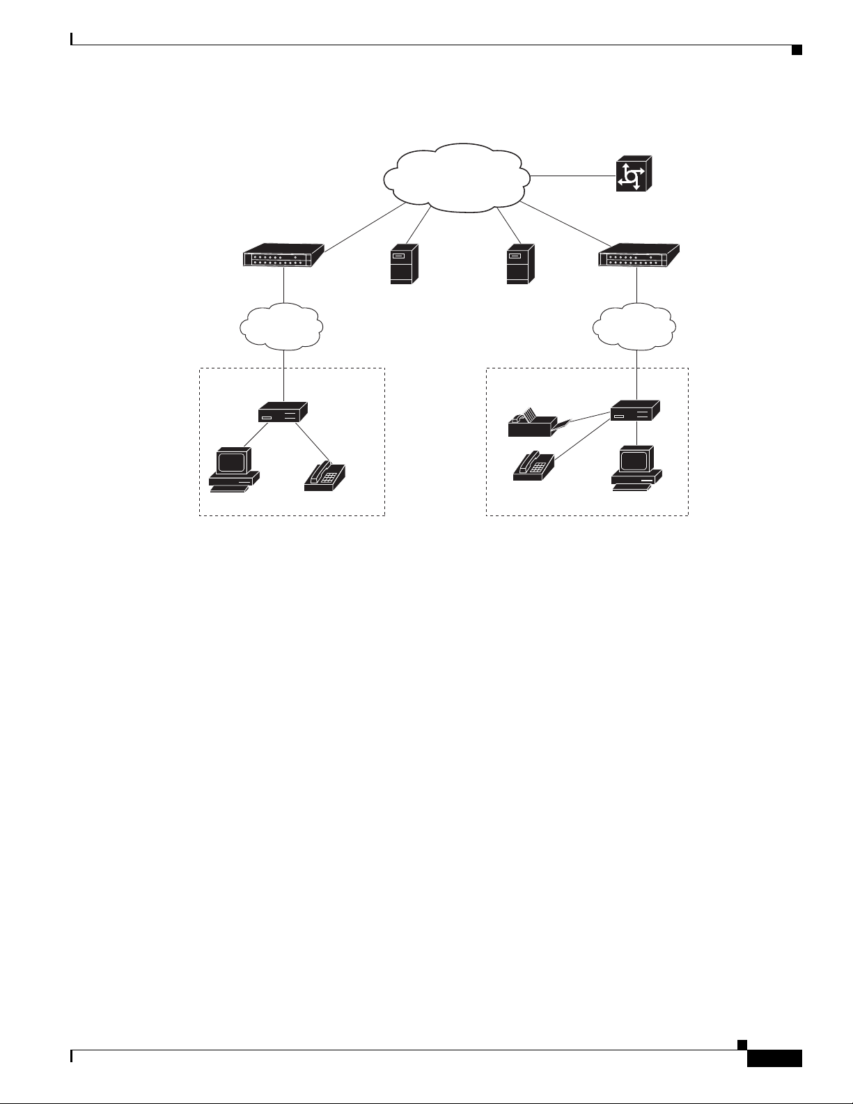
IP Telephony Services
The Cisco uBR7225VXR router supports the transmission of packetized voice and facsimile traffic over
the cable and IP backbone network. Figure 1-6 on page 1-9 shows a typical two-way configuration
involving Voice-over-IP (VoIP) telephony services.
1-8
Cisco uBR7225VXR Universal Broadband Router Hardware Installation Guide
OL-17309-02
Page 21
Chapter 1 Cisco uBR7225VXR Overview
271652
Gatekeeper or
calling agents
Service
provider
backbone
HFC
cable plant
HFC
cable plant
Remote
cable modem
Remote
cable modem
Gateway/PSTN
Calling party
Residence or SOHO*
subscriber site 1
Residence or SOHO*
subscriber site 2
Called party
Policy
server
*Small Office Home Office
Cisco
uBR7225VXR
Cisco
uBR7225VXR
Figure 1-6 Two-Way IP Telephony Network Example
Supported System Configurations Overview
Telco Return
In telco return configurations, the Cisco uBR7225VXR universal broadband router provides downstream
data flow from cable interface line cards connected to the cable system and accepts upstream traffic via
a combination of the local PSTN and IP network path that terminates at the Cisco uBR7225VXR router.
Upstream data transmission takes place over a telephone modem (external or internal to a
cable interface, as well as a cable interface line card in a PC, based on the third-party cable interface
vendor) connected to an analog telephone line. Figure 1-7 on page 1-10 illustrates a telco return
configuration.
OL-17309-02
Cisco uBR7225VXR Universal Broadband Router Hardware Installation Guide
1-9
Page 22
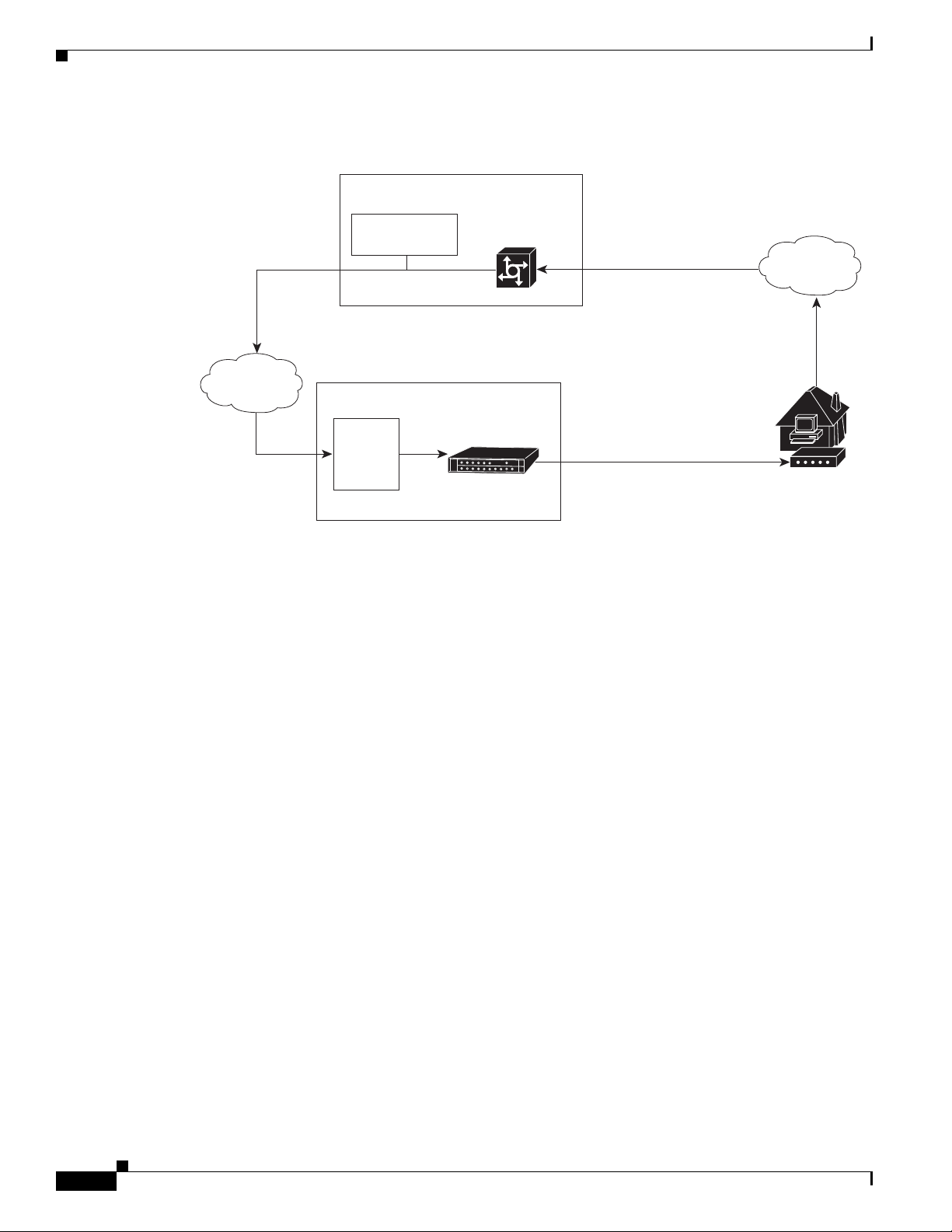
Hardware Component Descriptions
Figure 1-7 Telco Return Network Example
Chapter 1 Cisco uBR7225VXR Overview
IP network access
Cisco network
access server
Cisco
uBR7225VXR
IP network
RADIUS dial
security server
Headend or hub
DHCP
TFTP
TOD
servers
Hardware Component Descriptions
Most Cisco uBR7225VXR universal broadband router components are field-replaceable units (FRUs).
These units, unless otherwise noted, are OIR compatible. See the “Online Insertion and Removal”
section on page 5-1
FRU documentation (instructions on installing, removing, and replacing) is located at the following
URL:
PPP connection between
remote cable modem
and network access server
established following
authentication
HFC downstream
including TCD messages
PSTN
Upstream
Subscriber
cable modem
271653
http://www.cisco.com/en/US/products/hw/routers/ps341/prod_installation_guides_list.html
The following components are described:
• Network Processing Engine, page 1-10
• Cisco Cable Interface Line Cards, page 1-12
• Power Supplies, page 1-13
• Fan Trays, page 1-14
• Cisco uBR7225VXR Chassis, page 1-17
• Subchassis and Midplane, page 1-17
• CompactFlash Disk, page 1-18
Network Processing Engine
The network processing engine (NPE) maintains and executes the system management functions for the
Cisco uBR7225VXR router. The network processing engine performs the following system management
functions:
Cisco uBR7225VXR Universal Broadband Router Hardware Installation Guide
1-10
OL-17309-02
Page 23

Chapter 1 Cisco uBR7225VXR Overview
• Sending and receiving routing protocol updates
• Managing tables, caches, and buffers
• Monitoring interface and environmental status
• Providing Simple Network Management Protocol (SNMP) management and console/Telnet
interface
• Accounting and switching of data traffic
• Booting and reloading images
Refer to Network Processing Engine and Network Services Engine Installation and Configuration, for
specifications, and removal and replacement instructions for these components. View the document
online at the following URL:
http://www.cisco.com/en/US/docs/routers/7200/install_and_upgrade/network_process_engine_install_
config/npense.html
A CPU reset button is located on the NPEs’ faceplate. The CPU reset button resets the entire system.
Caution To prevent system errors and problems, use the CPU reset button only at the direction of your service
representative.
Hardware Component Descriptions
NPE Comparisons
Note The Cisco uBR7200-NPE-G1 should use the boothelper image ubr7200-kboot-mz.122-33.SCA.bin
The network processing engines used in the Cisco uBR7225VXR router are the Cisco uBR7200-NPE-G1
and Cisco uBR7200-NPE-G2.
available from Cisco IOS Release 12.3(33)SCA and later. The Cisco uBR7200-NPE-G2 should use the
boothelper image ubr7200p-boot-mz.122-33.SCA1.bin available from Cisco IOS Release 12.3(33)SCB
and later.
NPE components:
• Reduced instruction set computing (RISC) microprocessor:
–
Cisco uBR7200-NPE-G1 with a 700-MHz Broadcom BCM1250 processor
–
Cisco uBR7200-NPE-G2 with a 1.67-GHz Motorola Freescale MPC7448 processor
• System controller:
–
Cisco uBR7200-NPE-G1 and Cisco uBR7200-NPE-G2 do not require an I/O controller.
• Upgradable memory modules:
–
Cisco uBR7200-NPE-G1—SDRAM: 256 MB (default), 512 MB, and 1 GB. There are two
DRAM memory slots, so 256 MB of memory consists of two 128-MB memory SODIMMs, 512
MB consists of two 256-MB memory SODIMMs, and 1 GB consists of two 512-MB memory
SODIMMs. It is necessary to have the same size SODIMM in each memory bank on an
NPE-G1. The type of DRAM memory being used on the NPE-G1 is double data-rate (DDR)
memory. DDR memory provides high-performance memory access rates.
OL-17309-02
Cisco uBR7225VXR Universal Broadband Router Hardware Installation Guide
1-11
Page 24

Hardware Component Descriptions
–
• Cache memory:
–
–
• Two environmental sensors for monitoring the cooling air as it leaves the chassis.
• Boot ROM for storing sufficient code for booting the Cisco IOS software.
For memory replacement instructions, refer to the Memory Replacement Instructions for the Network
Processing Engine or Network Services Engine and Input/Output Controller document at the following
URL:
http://www.cisco.com/en/US/docs/routers/7200/install_and_upgrade/npe-nse_memory_install/memory
.html
Chapter 1 Cisco uBR7225VXR Overview
Cisco uBR7200-NPE-G2—SDRAM: 1 GB (default) and 2 GB. There are two DRAM memory
slots, so 1 GB of memory consists of two 512-MB memory SODIMMs, and 2 GB consists of
two 1 GB memory SODIMMs. It is necessary to have the same size SODIMM in each memory
bank on an NPE-G2. The type of DRAM memory being used on the NPE-G2 is double data-rate
(DDR) memory. DDR memory provides high-performance memory access rates.
Cisco uBR7200-NPE-G1—16-MB packet memory on 256-MB SDRAM, and 32-MB packet
memory on 512-MB and 1-GB SDRAM.
Cisco uBR7200-NPE-G2—32-MB packet memory on 512-MB and 1-GB SDRAM.
Cisco Cable Interface Line Cards
Cisco cable interface line cards (also known as line cards), with internal IF-to-RF upconverters, serve as
the RF interface between the cable headend and both DOCSIS-based cable modems and
EuroDOCSIS-based cable modems and set-top boxes (STBs). Cisco cable interface line cards separate
downstream output and upstream input cable interfaces on the Cisco uBR7225VXR router to enable
downstream and upstream signal combining and splitting arrangements.
Cisco cable interface line cards can be used in both 6-MHz NTSC standard and 8-MHz PAL/SECAM
channel environments.
The cable interface line cards connect directly to the universal broadband router’s midplane. Cable
interface line cards installed in the Cisco uBR7225VXR router support OIR.
Caution To ensure the proper flow of cooling air across internal components, make sure that blank cable interface
line card is installed in an unoccupied chassis slot. Also make sure that power supply filler plates are
installed in unoccupied power supply bays.
For more information regarding specific cable interface line cards, refer to the Cisco uBR7200 Series
Cable Interface Line Card Hardware Installation Guide. To view the document online, go to the
following URL:
http://www.cisco.com/en/US/docs/interfaces_modules/cable/line_cards/installation/guide/mcxxfru.htm
l
1-12
Cisco uBR7225VXR Universal Broadband Router Hardware Installation Guide
OL-17309-02
Page 25

Chapter 1 Cisco uBR7225VXR Overview
Power Supplies
The Cisco uBR7225VXR router is equipped with one of the following power supplies:
• 300W AC-input power supply—The maximum AC-input power with single or dual power supply
configuration is 300W. The minimum Cisco IOS Release supported on this power supply is the
Cisco IOS Release 12.2(33)SCA.
• 540W AC-input power supply—The maximum AC-input power with single or dual power supply
configuration is less than 700W. The minimum Cisco IOS Release supported on this power supply
is the Cisco IOS Release 12.2(33)SCD.
Note Ensure that you do not use a combination of these power supplies in the Cisco uBR7225VXR router.
The power supply contains a main power switch, Input OK and Output OK LEDs, AC-input power
receptacle, and a two-hole grounding lug for the AC-input power supply. The grounding lug at the
rear-bottom portion of the chassis provides a ground connection for electrostatic discharge (ESD)
equipment.
The Cisco uBR7225VXR router supports an optional, second power supply for load-sharing and power
redundancy. If you purchased a Cisco uBR7225VXR router and you want to install a second power
supply, you must order the second power supply separately.
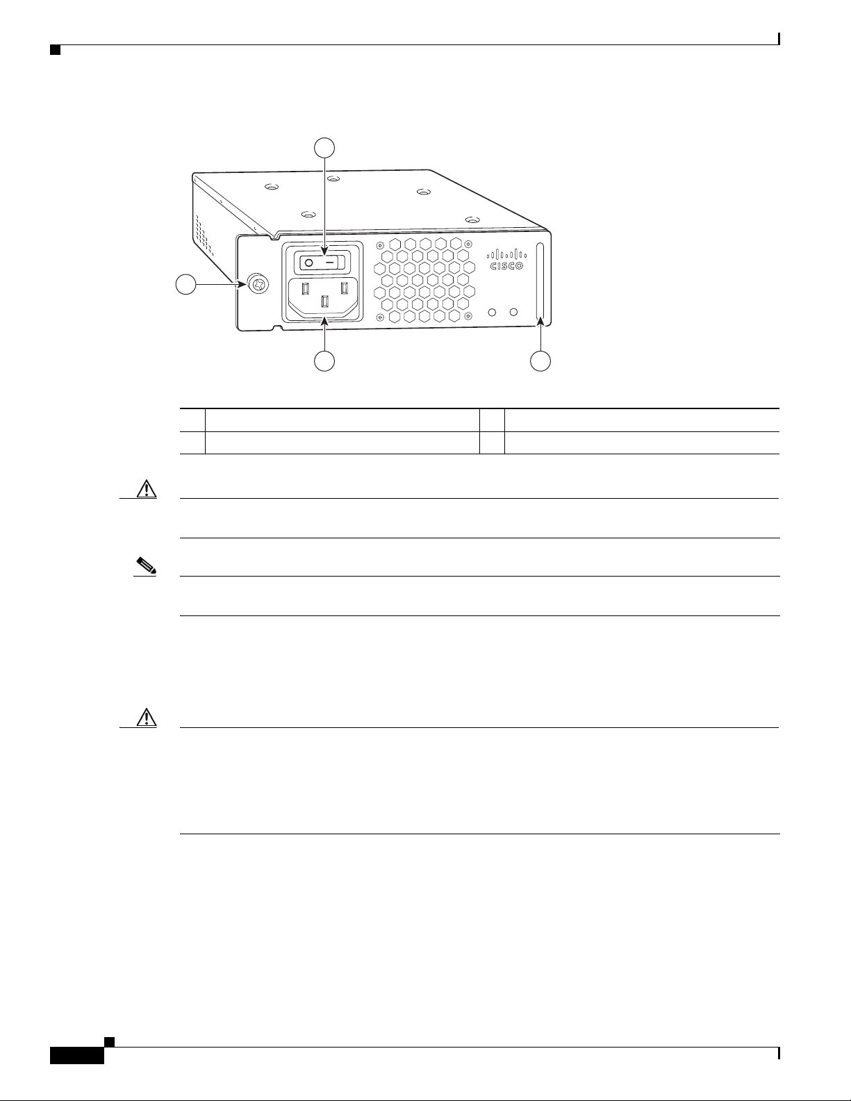
A handle on the AC-input power supply unit provides a grip point for removing and replacing the power
supply. (Figure 1-8 on page 1-14 shows the faceplate of the AC-input power supply.)
Hardware Component Descriptions
A single captive installation screw secures the power supply to the chassis and seats the power supply in
the router midplane. The AC-input power supply has a receptacle for an AC-input power cable. A
modular power cable connects the AC-input power supply to the site AC power source.
Detailed instructions for handling and replacing the Cisco uBR7225VXR universal broadband router
power supply is available in Cisco uBR7200 Series Universal Broadband Router AC Power Supply
Replacement Instructions.
This document is available on Cisco.com at the following URL:
http://www.cisco.com/en/US/docs/cable/cmts/ubr7200/installation/4848pwra.html
Note For the Cisco uBR7225VXR router, the 300W AC-input power supply has an electrical input current
rating of 4A with 100Vac input and the 540W AC-input power supply has an electrical input current
rating of 6.5A with 100Vac input.
OL-17309-02
Cisco uBR7225VXR Universal Broadband Router Hardware Installation Guide
1-13
Page 26
Hardware Component Descriptions
270698
PWR-UBR7225VXR-AC
100
-240 VA
C
4-2 A
50-60 Hz
Input
OK
Output
OK
1
23
4
Figure 1-8 Cisco uBR7225VXR AC-Input Power Supply
Chapter 1 Cisco uBR7225VXR Overview
Power switch
1
Handle
2
AC-input receptable
3
Captive installation screw
4
Caution To ensure adequate airflow across the Cisco uBR7225VXR power supplies, a power supply or a power
supply filler plate (with its attached air dam) must be installed in each power supply bay.
Note See Appendix A, “Cisco uBR7225VXR Router Specifications,” for AC-input power supply system
power specifications, including input voltage and operating frequency ranges.
The Cisco uBR7225VXR power supply shuts itself down when the input AC voltage, the output DC
voltage, or the internal temperature of the chassis exceeds allowable tolerances. When this occurs, one
or both of the power supply front panel LEDs will turn red. The Cisco uBR7225VXR power supply must
then be reset by manually switching the power switch off and then back on to allow the router to recover.
Caution When the input power to Cisco uBR7225VXR power supply is disconnected or lost, the power supply
enters a reset cycle for 10 seconds. Wait at least 10 seconds or move the power switch from one position
to the other to restart the power supply. For example, if the power supply was on when the power was
disconnected or lost, move the power switch to the off position and then back to the on position. If you
do not wait the full 10 seconds or move the power switch from one position to the other, the power supply
does not restart.
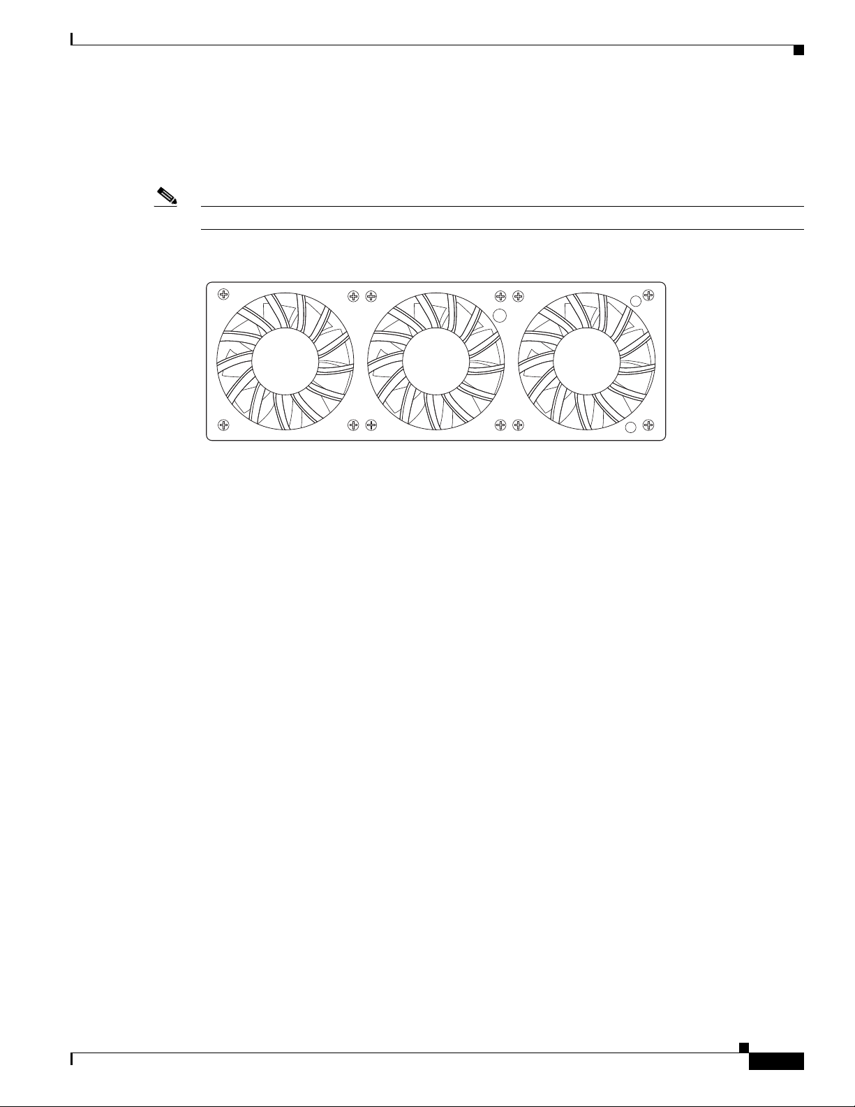
Fan Trays
The fan tray for the Cisco uBR7225VXR router, shown in Figure 1-9, consisting of three fans that are
attached to a metal tray, is located on the left side of the chassis (when viewing the router from the front)
and receives 12 VDC through a DC power harness that connects directly to the router midplane.
Cisco uBR7225VXR Universal Broadband Router Hardware Installation Guide
1-14
OL-17309-02
Page 27
Chapter 1 Cisco uBR7225VXR Overview
Temperature sensors on the network processing engine monitor the internal air temperature and send
warning messages when the internal air temperature approaches a specified threshold. If the internal
temperature exceeds the specified threshold, the system environmental monitor shuts down all internal
power to prevent equipment damage from excessive heat.
Note The Cisco uBR7225VXR router fan tray is not a field-replaceable unit.
Figure 1-9 Cisco uBR7225VXR Fan Tray
Hardware Component Descriptions
270537
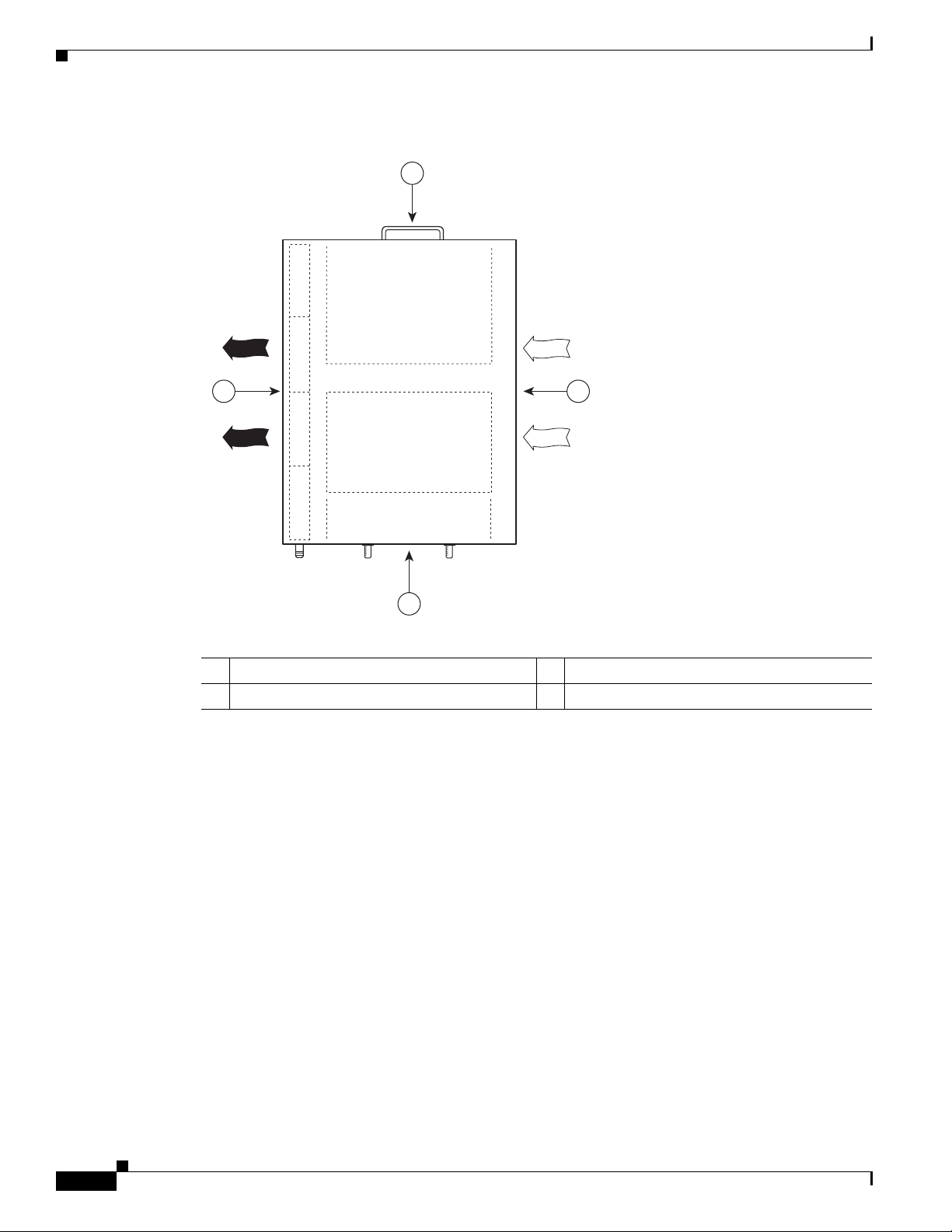
The fan tray draws cooling air in through the intake vent on the right side of the chassis (when viewing
the router from the front) and moves the air across the internal components and sends it out through the
exhaust vent on the left side of the chassis. Figure 1-10 shows the airflow through the router.
The left and right sides of the chassis must remain unobstructed to ensure adequate airflow and prevent
overheating inside the chassis; we recommend at least 3 inches of clearance. (See the “Site
Requirements” section on page 2-5.)
OL-17309-02
Cisco uBR7225VXR Universal Broadband Router Hardware Installation Guide
1-15
Page 28
Hardware Component Descriptions
Figure 1-10 Internal Airflow—Top View
4 2
Chapter 1 Cisco uBR7225VXR Overview
1
Power supply end
1
Inlet flow
2
271654
3
Cable interface line card end
3
Exhaust air (fan side)
4
1-16
Cisco uBR7225VXR Universal Broadband Router Hardware Installation Guide
OL-17309-02
Page 29
Chapter 1 Cisco uBR7225VXR Overview
270494
u
BR
7
2
2
5
-V
X
R
1
2
3
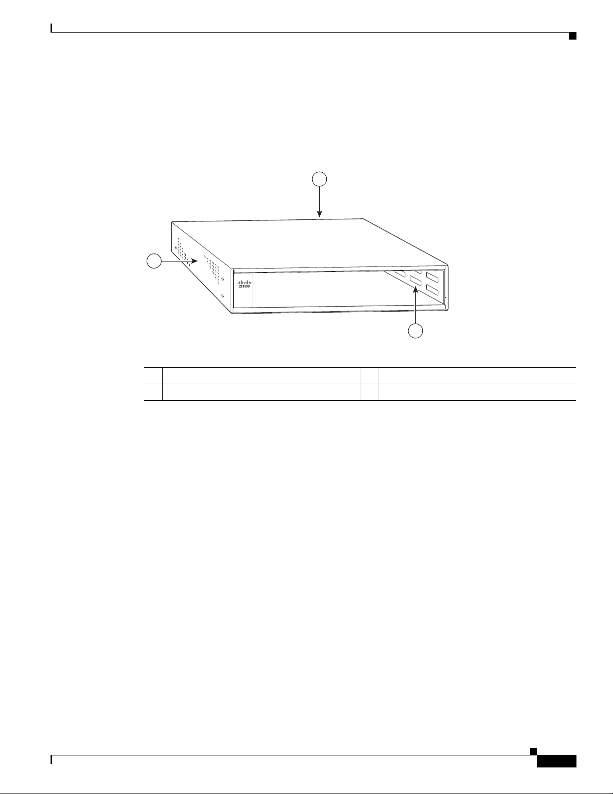
Cisco uBR7225VXR Chassis
The front of the chassis has two slots for cable interface line cards and one bay for the subchassis. See
Figure 1-11.
Figure 1-11 Cisco uBR7225VXR Chassis
Hardware Component Descriptions
Subchassis and midplane bay (at rear)
1
Cable interface line card slots
2
Subchassis and Midplane
The subchassis and midplane provide these functions for the Cisco uBR7225VXR router:
• Distributes power from the power supply.
• Bridges the peripheral component interconnect (PCI) buses from the cable interface line cards to the
Cisco uBR7200-NPE-G1 or the Cisco uBR7200-NPE-G2.
• Arbitrates traffic across the PCI buses.
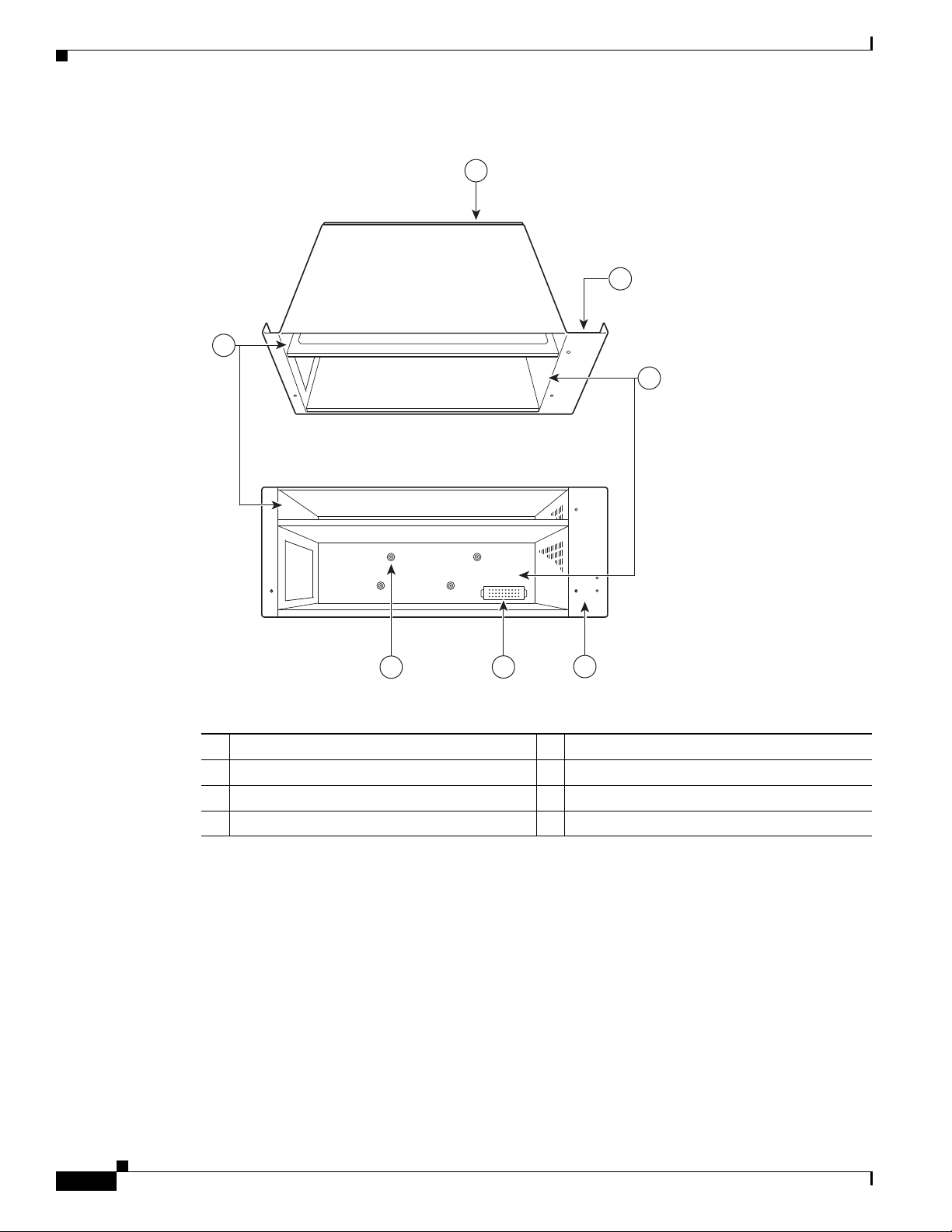
Cisco uBR7225VXR Subchassis
The subchassis (the rear of the router) has two bays for power supplies and one slot for a network
processing engine. (See Figure 1-12.) The cable interface card side of the Cisco uBR7225VXR router
midplane has two connectors for cable interface line cards.
The power supply side of the midplane has two connectors for power supplies and one connector for a
network processing engine. The midplane supplies DC power to the router’s internal components.
Refer to the Cisco uBR7200 Series Universal Broadband Router Subchassis and Midplane Replacement
Instructions at the following URL:
http://www.cisco.com/en/US/docs/cable/cmts/ubr7200/installation/5193sbm.html
3
Fan tray
OL-17309-02
Cisco uBR7225VXR Universal Broadband Router Hardware Installation Guide
1-17
Page 30
Hardware Component Descriptions
Figure 1-12 Cisco uBR7225VXR Subchassis and Midplane
7
Chapter 1 Cisco uBR7225VXR Overview
1
To p
2
3
Back
Midplane
1
Fan tray slot
2
Power supply bays
3
Fan tray slot
4
CompactFlash Disk
The Cisco uBR7225VXR universal broadband router has one CompactFlash Disk slot that uses
CompactFlash Disks. The device in this slot is always addressed as disk2: when using Cisco IOS
command-line interface (CLI) commands.
CompactFlash Disks are smaller in size than Type 2 Flash Disks but provide the same AT Attachment
(ATA) interface and equivalent functionality. This interface complies with the ANSI ATA Interface
Document X3T13.1153 D Rev. 9 specification. The CompactFlash Disk provides 512 MB or 1 GB of
storage space.
271655
6
5
4
Power supply receptacle
5
Captive installations screws (6)
6
Network processing engine slot
7
1-18
Cisco uBR7225VXR Universal Broadband Router Hardware Installation Guide
OL-17309-02
Page 31

Chapter 1 Cisco uBR7225VXR Overview
The CompactFlash Disk has controller circuitry that allows it to emulate a hard disk and automatically
maps out bad blocks and performs automatic block erasure. The CompactFlash Disk also provides the
capability to allocate noncontiguous sectors, which eliminates the need for the squeeze command (which
was required with older-style linear flash memory cards to recover the space used by deleted files).
The CompactFlash Disk also supports the Cisco IOS File System feature, which provides a single
interface to all of the router’s file systems, including the Flash Disks and flash memory, as well as
network file systems such as File Transfer Protocol (FTP) and Trivial FTP (TFTP) servers.
Note All CompactFlash Disks must be formatted before their initial use. CompactFlash Disks shipped with
the NPE-G2 are formatted at the factory, but spare memory cards are not formatted.
Hardware Component Descriptions
OL-17309-02
Cisco uBR7225VXR Universal Broadband Router Hardware Installation Guide
1-19
Page 32

Hardware Component Descriptions
Chapter 1 Cisco uBR7225VXR Overview
1-20
Cisco uBR7225VXR Universal Broadband Router Hardware Installation Guide
OL-17309-02
Page 33

CHAP T E R
2
Preparing the Cisco uBR7225VXR Router for Installation
This chapter describes the site requirements for installing the Cisco uBR7225VXR universal broadband
router and contains the following sections:
• Safety Recommendations, page 2-1
• Site Requirements, page 2-5
• Required Network Information, page 2-7
• Installation Tools, page 2-8
• Rack-Mount and Cable-Management Kit, page 2-8
• Equipment Required to Verify Your Plant’s RF Setup, page 2-9
• Shipping Container Contents, page 2-9
• Provisioning the Cable Headend, page 2-10
• Site Preparation Checklist, page 2-17
• Component Checklists, page 2-18
Safety Recommendations
The following safety guidelines will help to ensure your safety and protect the equipment. This list does
not cover all potentially hazardous situations, so be alert. Before installing, configuring, or maintaining
the Cisco uBR7225VXR router, review the safety warnings listed in the Regulatory Compliance and
Safety Information for Cisco uBR7200 Series Universal Broadband Routers at the following URL:
http://www.cisco.com/en/US/docs/cable/cmts/ubr7200/regulatory/compliance/ub72rcsi.html
The installation of your Cisco uBR7225VXR universal broadband router should be in compliance with
national and local electrical codes.
Other safety issues to be aware of:
• Never attempt to lift an object that might be too heavy for you to lift by yourself.
• Always turn all power supplies off and unplug all power cables before opening the chassis.
• Always unplug the power cable before installing or removing a chassis.
• Keep the chassis area clear and dust-free during and after installation.
• Keep tools and chassis components away from walk areas.
OL-17309-02
Cisco uBR7225VXR Universal Broadband Router Hardware Installation Guide
2-1
Page 34

Safety Recommendations
Chapter 2 Preparing the Cisco uBR7225VXR Router for Installation
• Do not wear loose clothing, jewelry (including rings and chains), or other items that could get caught
in the chassis.
• For systems with installed AC-input power supplies, the Cisco uBR7225VXR router ships with a
3-wire electrical grounding-type plug, which only fits into a grounding-type power outlet. This is a
safety feature. The equipment grounding should be in accordance with local and national electrical
codes.
• The Cisco uBR7225VXR router operates safely when it is used in accordance with its marked
electrical ratings and product usage instructions.
Warning
Note For Australia and New Zealand, equipment is to be installed and maintained by service personnel only
Only trained and qualified personnel should be allowed to install or replace this equipment.
Statement 1030
as defined by AS/NZS 3260 Clause 1.2.14.3 Service Personnel.
Warning
Ultimate disposal of this product should be handled according to all national laws and regulations.
Statement 1040
Lifting the Cisco uBR7225VXR Router Safely
Before you install the router, ensure that your site configuration is properly designed and prepared so
that you can avoid having to move the router later to accommodate power sources and network
connections.
A fully-configured Cisco uBR7225VXR router (with two 300W power supplies) weighs approximately
48 pounds (21.8 kilograms).
Whenever you lift a chassis or any heavy object, follow these guidelines:
• Always disconnect all external cables before lifting or moving the chassis.
2-2
• Do not attempt to lift the chassis by yourself; have someone assist you (see Figure 2-1 on page 2-3).
• Ensure that your footing is solid, and balance the weight of the object between your feet.
• Lift the chassis slowly; never move suddenly or twist your body as you lift.
• Keep your back straight and lift with your legs, not your back. If you must bend down to lift the
chassis, bend at the knees, not at the waist, to reduce the strain on your lower back muscles.
• Lift the chassis from the bottom; grasp the underside of the chassis exterior with both hands.
Cisco uBR7225VXR Universal Broadband Router Hardware Installation Guide
OL-17309-02
Page 35

Chapter 2 Preparing the Cisco uBR7225VXR Router for Installation
Figure 2-1 Lifting the Chassis (Cisco uBR7246 Router Shown)
Safety Recommendations
271656
Warning
Two people are required to lift the chassis. Grasp the chassis underneath the lower edge and lift with
both hands. To prevent injury, keep your back straight and lift with your legs, not your back. To prevent
damage to the chassis and components, never attempt to lift the chassis with the handles on the
power supplies or on the interface processors, or by the plastic panels on the front of the chassis.
These handles were not designed to support the weight of the chassis.
Safety with Electricity
Follow these basic guidelines when working with any electrical equipment:
• Before beginning any procedures requiring access to the chassis interior, locate the emergency
power-off switch for the room in which you are working.
• Carefully examine your work area for possible hazards such as moist floors, ungrounded power
extension cables, and missing safety grounds.
• Disconnect all power and external cables before installing or removing a chassis.
• Never assume that power has been disconnected from a circuit; always check.
• Do not perform any action that creates a potential hazard to people or makes the equipment unsafe.
• Do not work alone if potentially hazardous conditions exist.
• Never install equipment that appears damaged.
Statement 5
OL-17309-02
Caution Yo u must power down the system before removing or replacing the network processing engine. The cable
interface line cards and redundant power supplies are designed to be removed and replaced while the
system is operating, without presenting an electrical hazard or damage to the system.
Cisco uBR7225VXR Universal Broadband Router Hardware Installation Guide
2-3
Page 36

Safety Recommendations
Chapter 2 Preparing the Cisco uBR7225VXR Router for Installation
Warning
Warning
Warning
The telecommunications lines must be disconnected 1) before unplugging the main power connector
and/or 2) while the housing is open.
Before working on a chassis or working near power supplies, unplug the power cord on AC units;
disconnect the power at the circuit breaker on DC units.
Do not work on the system or connect or disconnect cables during periods of lightning activity.
Statement 1001
Statement 89
In addition, use the guidelines that follow when working with any equipment that is disconnected from
a power source, but still connected to telephone wiring or other network cabling:
• Never install telephone wiring during a lightning storm.
• Never install telephone jacks in wet locations unless the jack is specifically designed for wet
locations.
• Never touch uninsulated telephone wires or terminals unless the telephone line has been
disconnected at the network interface.
• Use caution when installing or modifying telephone lines.
Preventing Electrostatic Discharge Damage
Statement 246
Electrostatic discharge (ESD) damage, which occurs when electronic cards or components are
improperly handled, can result in complete or intermittent system failures. The network processing
engine and cable interface line cards consist of a printed circuit board that is fixed in a metal carrier.
Electromagnetic interference (EMI) shielding, connectors, and a handle are integral components of the
carrier. Although the carrier helps protect the boards, use an antistatic strap whenever handling the
network processing engine and cable interface cards. Handle the carriers by the handles and the carrier
edges only; never touch the boards or connector pins.
Caution Always tighten the captive installation screws on the network processing engine and cable interface line
cards. These screws prevent accidental removal, provide proper grounding for the system, and help
ensure that the bus connectors are properly seated in the midplane.
Following are guidelines for preventing ESD damage:
• Always use an ESD wrist strap or ankle strap and ensure that it makes good skin contact.
• When handling a removed network processing engine or cable interface line card, make sure that the
equipment end of your ESD strap is attached to an unfinished chassis surface of the router; do not
touch the printed circuit board, and avoid contact between the printed circuit board and your
clothing. Always place the network processing engine or cable interface line card component side
up on an antistatic surface or in a static shielding bag. If you are returning the item to the factory,
immediately place it in a static shielding bag.
2-4
Cisco uBR7225VXR Universal Broadband Router Hardware Installation Guide
OL-17309-02
Page 37

Chapter 2 Preparing the Cisco uBR7225VXR Router for Installation
• Ensure that the network processing engine is fully inserted in its chassis slot and the captive
installation screws are tightened. The captive installation screws prevent accidental removal,
provide proper grounding for the system, and help ensure that the bus connectors are seated in the
midplane.
• Ensure that each cable interface line card is fully inserted in its chassis slot and that its captive
installation screws are tightened.
Caution For safety, periodically check the resistance value of the antistatic strap. The measurement should be
between 1 and 10 megohms.
Site Requirements
To ensure normal operation and avoid unnecessary maintenance, plan your site configuration and
prepare your site before installation. Take into account the following criteria:
• Verify that your cable network meets system requirements and DOCSIS or EuroDOCSIS
downstream and upstream specifications.
• Select forward and reverse channel frequencies from the range specified in your channel plan.
• Make sure that the site maintains an ambient temperature of 32 to 104
area around the chassis as free from dust as is practical.
Site Requirements
o
F (0 to 40oC), and keep the
Note To locate the most reliable channels for your downstream and upstream channel plans, we recommend
that you perform a sweep of all available channels for at least a 24-hour period to verify the presence or
absence of impulse or ingress noise.
AC Power
The AC-input power supply uses a power factor corrector that allows the Cisco uBR7225VXR router to
operate on input voltage and frequency within the ranges of 100 to 240 VAC and 50/60 Hz.
Note We recommend an uninterruptable power source to protect against power failures at your site. For the
Cisco uBR7225VXR router, the 300W AC-input power supply has an electrical input current rating of
4A with 100Vac input and the 540W AC-input power supply has an electrical input current rating of 6.5A
with 100Vac input.
See Appendix A, “Cisco uBR7225VXR Router Specifications,” for system power specifications,
including input voltage and operating frequency ranges.
Site Environment
Table 2-1 lists the operating and nonoperating environmental site requirements. The following ranges
are those within which the Cisco uBR7225VXR router continues to operate; however, a measurement
that is approaching the minimum or maximum of a range indicates a potential problem. You can maintain
normal operation by anticipating and correcting environmental anomalies before they approach the
minimum or maximum of an operating range.
OL-17309-02
Cisco uBR7225VXR Universal Broadband Router Hardware Installation Guide
2-5
Page 38

Chapter 2 Preparing the Cisco uBR7225VXR Router for Installation
Site Requirements
To provide airflow through the Cisco uBR7225VXR router, cooling air is drawn in through the air intake
vent on the right side of the chassis (when viewing the router from the front) and is exhausted through
the left side of the chassis. Keep the right and left sides of the chassis clear of obstructions and away
from the exhaust of other equipment.
Note The Cisco uBR7225VXR router is suitable for installation in Network Telecommunication Facilities and
locations where the National Electrical Code (NEC) applies. The Cisco uBR7225VXR router is not
intended for installation in outside plant (OSP) locations.
Table 2-1 Specifications for Operating and Nonoperating Environments
Specification Minimum Maximum
Temperature, ambient operating 32
Temperature, ambient nonoperating and storage –4
Humidity, ambient (noncondensing) operating 10% 90%
Humidity, ambient (noncondensing) nonoperating
and storage
Altitude, operating and nonoperating Sea level 10,000 feet (3,050 meters)
Vibration, operating 5 to 200 Hz, 0.5 g (1 oct./min.) –
Vibration, nonoperating 5 to 200 Hz, 1 g (1 oct./min.)
o
F (0oC) 104oF (40oC)
o
F (–20oC) 149oF (65oC)
5% 95%
–
200 to 500 Hz, 2 g (1 oct./min.)
Site Configuration: Maintaining Normal Operation
Planning a proper location for the Cisco uBR7225VXR universal broadband router and the layout of
your equipment rack or wiring closet are essential for successful system operation. Equipment placed
too close together or inadequately ventilated can cause system overtemperature conditions. In addition,
chassis panels made inaccessible by poor equipment placement can make system maintenance difficult.
Following are precautions that can help avoid problems during installation and ongoing operation.
General Precautions
Follow these general precautions when planning your equipment locations and connections:
• Use the show environment command regularly to check the internal system status. The
environmental monitor continually checks the interior chassis environment; it provides warnings for
high temperature and maximum and minimum voltages and creates reports on any occurrences. If
warning messages are displayed, take immediate action to identify the cause and correct the
problem.
• We recommend keeping the Cisco uBR7225VXR router off the floor and out of any area that tends
to collect dust, excessive condensation, or water.
• Follow ESD prevention procedures to avoid damage to equipment. Damage from static discharge
can cause immediate or intermittent equipment failure.
2-6
Cisco uBR7225VXR Universal Broadband Router Hardware Installation Guide
OL-17309-02
Page 39

Chapter 2 Preparing the Cisco uBR7225VXR Router for Installation
• Ensure that the network processing engine, cable interface line cards, any blank cable interface line
cards, power supplies, and any power supply filler plates are in place and secure. The fans direct
cooling air throughout the chassis interior; a loose component or empty slot can redirect the airflow
away from active components and cause overheating.
Power Considerations
Follow these precautions and recommendations when planning power connections to the
Cisco uBR7225VXR router:
• Check the power at your site before installation and periodically after installation to ensure that you
are receiving clean power. Install a power conditioner and appropriate surge suppression if
necessary.
• Install proper grounding to avoid damage from lightning and power surges.
Required Network Information
Required Network Information
After you install the chassis, your system administrator must configure the individual and system
interfaces before you connect your system to external networks. Refer to the following documentation
for configuration information.
Cisco uBR7200 Series Software Configuration Guide at the following URL:
http://www.cisco.com/en/US/docs/cable/cmts/ubr7200/configuration/guide/cr72scg.html
Cisco IOS CMTS Cable Software Configuration Guide at the following URL:
http://www.cisco.com/web/techdoc/cable/Config/Sw_conf.html
Cisco IOS CMTS Cable Command Reference Guide at the following URL:
http://www.cisco.com/en/US/docs/ios/cable/command/reference/cbl_book.html
Before You Begin
Be prepared with global (system-wide) parameters such as:
• Hostnames
• Passwords
• Routing protocols
• Configuration information for each interface, such as:
Following is the information you might need, depending on the services you plan to offer:
–
Addresses
–
Rates or speeds of operation
–
Routing protocol specifics
OL-17309-02
• Hostname for the router.
• Passwords to prevent unauthorized privileged-level access to the EXEC command interpreter and
for individual virtual terminal lines.
• Protocols you plan to route.
Cisco uBR7225VXR Universal Broadband Router Hardware Installation Guide
2-7
Page 40

Installation Tools
• IP addresses and subnet masks, if you are routing IP.
• Dial-up access telephone numbers, usernames, and passwords for telco return operation.
• RADIUS security and accounting configuration.
• Gateway and gatekeeper zone configuration for your H.323 VoIP network.
• Gateway and call-agent configuration for your SGCP VoIP network.
• Zone names, network numbers, or node numbers for the new interfaces, if required.
• Operating speeds for specific interfaces—For example, serial interfaces operate at speeds of up to
2 Mbps. The speed of an interface often depends on the speed of the remote device to which it is
attached.
Installation Tools
Your Cisco uBR7225VXR universal broadband router chassis is fully assembled at the factory; no
assembly is required. However you will need the following tools and equipment to install the chassis and
the rack-mount and cable-management kit:
Chapter 2 Preparing the Cisco uBR7225VXR Router for Installation
• Number 2 Phillips screwdriver
• 3/16-inch flat-blade screwdriver
• 7/16-inch flat-blade screwdriver
• 7/16-inch torque wrench for connecting coaxial cables to the cable F-connectors on the
cable interface line cards—Recommended torque is 20 inch-pounds (optional)
• Tape measure (optional)
• Level (optional)
Rack-Mount and Cable-Management Kit
The rack-mount and cable-management kit includes the following parts:
• Two rack-mount brackets for mounting the chassis in the rack.
• Cable-management bracket to relieve the strain on installed cable interface line card interface
cables.
• Eight M4 x 6-mm Phillips flathead screws to secure the rack-mount brackets to the chassis.
• Four M3 x 6-mm Phillips panhead screws to secure the cable-management bracket to the chassis.
• Four 10/32 x 3/8-inch slotted binderhead screws to secure the rack-mount brackets to the rack rails.
For more information on the rack-mount brackets and cable-management bracket, refer to the
“Cisco uBR7225VXR Router Chassis Rack-Mounting Options” section on page 3-2.
2-8
Cisco uBR7225VXR Universal Broadband Router Hardware Installation Guide
OL-17309-02
Page 41

Chapter 2 Preparing the Cisco uBR7225VXR Router for Installation
Equipment Required to Verify Your Plant’s RF Setup
Equipment Required to Verify Your Plant’s RF Setup
To verify your plant’s RF setup, you need the following:
• RF spectrum analyzer
• For coaxial cabling:
–
Diplex filters/splitters
–
Coaxial cable crimping tool
–
New coaxial cable
–
Coaxial jumpers that are at least 2 to 3 feet long (maximum of 5 feet)
• For fiber networks, optical receivers for each upstream optical path
• Assorted RF attenuators (with at least two 20-dB attenuators)
Note For headend RF and data setups, refer to Chapter 4, “Connecting the Cisco uBR7225VXR Router to the
Cable Headend.” Refer to Appendix F, “Manufacturers for Headend Provisioning Requirements,” for a
list of manufacturers. Refer to Appendix C, “Cable Specifications,” for coaxial cabling specifications.
In addition, you might need the following:
• Crossover Ethernet cable with RJ-45 connectors—If you plan to connect a computer directly to an
Ethernet port in the Cisco uBR7225VXR router, you need this type of cable.
• Fast Ethernet transceiver.
• DOCSIS cable modem or DOCSIS-based STB and CPE devices to test full system functionality.
Note When the Cisco uBR7225VXR router starts running, IF downstream output is generated. For more
information, see the “Powering On the Cisco uBR7225VXR Router” section on page 3-18.
Shipping Container Contents
When you receive your Cisco uBR7225VXR universal broadband router, use the following procedure to
check the contents of the shipping container. Use the Cisco uBR7225VXR Router Installation Checklist
or the “Component Checklists” section on page 2-18 to ensure you received all the components that you
ordered.
Note Do not discard the shipping container. You will need the container if you move or ship your
Cisco uBR7225VXR router in the future.
Verifying the Shipping Container Contents
Step 1 Verify that the following are included in the shipping container (the accessories box might be separate):
• One Cisco uBR7225VXR universal broadband router chassis containing all of the components you
ordered for your system (except the rack-mount and cable-management kit)
Cisco uBR7225VXR Universal Broadband Router Hardware Installation Guide
OL-17309-02
2-9
Page 42

Provisioning the Cable Headend
• One or more accessories boxes (some or all might be shipped separately)
Step 2 Check the contents of the accessories box against the “Component Checklist” and the packing slip to
verify that you received all listed equipment, which should include the following:
• One modular power cable for an AC-input power supply. (If you purchased a Cisco uBR7225VXR
router with a redundant power supply, you should receive two power cables.)
• One rack-mount and cable-management kit (3 brackets and 14 mounting screws).
• Optional equipment that you ordered, such as network interface cables, transceivers, or special
connectors.
• CNR or CSRC provisioning documentation, or both.
• Cisco IOS software documentation, if ordered.
Step 3 Verify that the number of cable interface line cards installed in your Cisco uBR7225VXR router matches
the number of cable interface line cards that you ordered.
Step 4 Refer to Appendix G, “Site Log,” then to the “Cisco uBR7225VXR Router Chassis Rack-Mounting
Options” section on page 3-2 to begin the installation.
Chapter 2 Preparing the Cisco uBR7225VXR Router for Installation
Provisioning the Cable Headend
This section describes the necessary preparations to make at the cable headend before you install the
Cisco uBR7225VXR universal broadband router.
Two-Way Data and VoIP
To prepare for two-way data operation, including digitized voice and fax, ensure that the following
conditions are met:
• The cable headend equipment is properly aligned and certified for two-way transmission based on
procedures provided by the manufacturers of the equipment and in accordance with DOCSIS or
EuroDOCSIS RF Interface Specifications.
• The cable headend is wired for narrowcast downstream data transmission.
• The cable headend is wired to supply an RF feed from the upstream fiber-optic receivers to the
Cisco uBR7225VXR router.
• Upstream frequencies are allocated for data transmission.
• Upstream impairments are measured and understood, and comply with recommendations in
DOCSIS or EuroDOCSIS RF interface specifications.
• Upstream ports are configured as appropriate to support frequency agility.
• Downstream frequencies are assigned.
• Internet connectivity is established.
2-10
• Internet addresses are obtained and allocated.
• All RF connectivity is verified.
Cisco uBR7225VXR Universal Broadband Router Hardware Installation Guide
OL-17309-02
Page 43

Chapter 2 Preparing the Cisco uBR7225VXR Router for Installation
Note For a VoIP system using H.323, ensure that the CMTS has been properly provisioned with equipment
such as VoIP gateways and gatekeepers. For SGCP-based VoIP systems, ensure that the CMTS has been
properly provisioned with equipment such as VoIP gateways and call-agents.
Headend Certification
The cable headend plant must pass both analog and digital certification:
• In the United States, the Federal Communications Commission (FCC) mandates minimum technical
performance requirements for cable systems.
• For international requirements, consult with local agencies for certification requirements.
The digital certification process is described in Chapter 4, “Connecting the Cisco uBR7225VXR Router
to the Cable Headend.”
Diplex Filters
Provisioning the Cable Headend
For coaxial cabling, diplex filters must be installed in the RF path between the cable interface cards in
the Cisco uBR7225VXR universal broadband router and cable interfaces and STBs. Diplex filters
separate the downstream signals from the upstream signals.
Note For fiber optics, laser transmitters and optical receivers handle the frequency separation of upstream and
downstream. Refer to the “Receivers” section on page 2-11.
High-frequency signals flow in the downstream direction from the Cisco uBR7225VXR router to
cable interfaces and STBs. Low-frequency signals flow in the upstream direction from the
cable interfaces to the Cisco uBR7225VXR router.
A diplex filter has three ports: low, high, and common. The downstream attaches to the high port because
it runs at high frequency. The upstream attaches to the low port because it runs at a low frequency. The
common port attaches to a splitter attached to one or more cable interfaces and STBs.
In two-way cable networks, the diplex filter takes the upstream and downstream and combines them on
one cable for the cable interface. The downstream output signal from the Cisco uBR7225VXR router
runs through the upconverter and then enters the high filter port of the diplex filter. The signal exits the
common port of the filter and is distributed to the cable interfaces. The upstream signal from the cable
modem enters the common port of the diplex filter and flows to the upstream receive ports of the
Cisco uBR7225VXR cable interface line cards through the diplex filters’ low port.
Note Appendix F, “Manufacturers for Headend Provisioning Requirements,” provides a list of diplex filter
manufacturers and websites for more information.
Receivers
OL-17309-02
If the upstream channels of your cable plant terminate at the headend over fiber-optic lines, ensure that
you have a receiver allocated for each upstream in your network.
Cisco uBR7225VXR Universal Broadband Router Hardware Installation Guide
2-11
Page 44

Provisioning the Cable Headend
DHCP, DNS, TFTP, and TD Servers
A DHCP server must be installed at the headend. The DHCP server must also offer a time-of-day (TD)
server option that is compliant with RFC 868.
In conjunction with the DHCP server, a Domain Name System (DNS) server must be installed to
translate names of network nodes into IP addresses. A TFTP server must be installed to facilitate the
transfer of DOCSIS configuration files over the broadband network.
Cisco provides a configuration tool with every Cisco uBR7225VXR universal broadband
router—Cisco Network Registrar (CNR)—to automate dynamic IP address allocation to
cable interfaces, PCs, and other devices on the broadband network. CNR provides integrated DHCP and
DNS services for your network configuration.
Telco Return
To support telco return, ensure that:
• Your downstream plant meets DOCSIS or EuroDOCSIS specifications.
Chapter 2 Preparing the Cisco uBR7225VXR Router for Installation
• Your headend is wired for narrowcast downstream data transmission.
• You have assigned downstream frequencies.
• All equipment needed to support upstream traffic over the PSTN, as well as to monitor telco return
service features is installed. Key components include:
–
Dial-up access server (for example, the Cisco AS5300 or Cisco AS5800)
–
RADIUS dial security server
• All third-party, telco return cable interfaces are DOCSIS-compliant.
• Your Cisco IOS software image supports telco return functionality.
The following sections describe CMTS equipment necessary to support telco return service.
Dial-Up/Remote Access Servers
Because a telco return cable network relies on the local telephone system to complete the upstream data
path to the Cisco uBR7225VXR router, you need to be sure that you provision your network with a
dial-up access server and other required equipment through which remote cable interfaces will gain
access to your headend.
RADIUS Dial Security Servers
After remote telco return cable interfaces have initiated dial-up to the CMTS via the network access
server, a RADIUS dial security server typically authenticates their respective usernames and passwords
or MAC address and passwords and then determines whether or not to allow the connection.
In addition to the dial-up numbers provided in telephony channel descriptor (TCD) messages originating
from the Cisco uBR7225VXR router, username and password information is included in TCD messages
to validate the cable interface’s upstream connection. After dialing in to the network access server, the
username and password portions of the TCD messages are passed through a RADIUS dial access server
for authentication before the upstream data path can be completed. (See Figure 2-2.)
2-12
Cisco uBR7225VXR Universal Broadband Router Hardware Installation Guide
OL-17309-02
Page 45
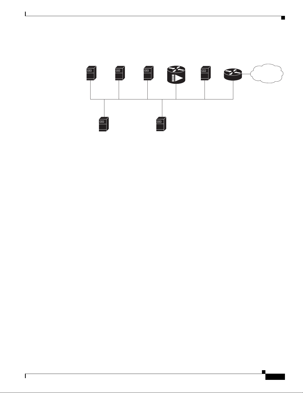
Chapter 2 Preparing the Cisco uBR7225VXR Router for Installation
Figure 2-2 Servers on an HFC Network
Provisioning the Cable Headend
S
Cisco Network
Registrar
DHCP/DNS server
TFTP
server
*A remote access server is required on an HFC network only
when you want to offer VoIP using H.323 or telco return service.
ecurity
server
(optional)
Log
server
(optional)
Time-of-day
uBR7225VXR
server
Cisco
Remote
access serve
Authentication, Authorization, and Accounting Servers
Authentication, authorization, and accounting (AAA) servers are essential to the network, because they
typically monitor usage for subscriber billing and record keeping. AAA features call upon a RADIUS
security server to help authenticate and monitor users’ access.
Cisco 7500
r*
series router
Internet
271657
VoIP Gateways and Gatekeepers
To support digitized voice transmission on uBR7225VXR router using Cisco IOS Release 12.2(33)SCA
CMTS images, be sure to include VoIP gateways and gatekeepers in your configuration. Cisco IOS
Release 12.2(33)SCA supports VoIP by using the H.323 protocol. VoIP gateways convert IP-based voice
packets into standard PSTN voice traffic, making the process of placing calls over the IP network
transparent to users.
VoIP gatekeepers manage H.323-compliant gateways throughout the network. Gatekeepers also manage
traffic between their local cable system networks, as well as the networks of other VoIP gatekeepers.
VoIP SGCP Pass-Through
To support digitized voice transmission using Simple Gateway Control Protocol (SGCP), be sure to
include VoIP gateways and external call control elements (often referred to as call-agents) in your
configuration. Cisco IOS Release 12.2(33)SCA and later versions support VoIP communication using
the SGCP 1.1 protocol on uBR7225VXR. Just as with H.323 systems, VoIP gateways in an SGCP
environment convert IP-based voice packets into standard PSTN voice traffic, making the process of
placing calls over the IP network transparent to users.
Call-agents manage SGCP-compliant gateways throughout the network, allowing them to engage in
common channel signaling (CCS) over a 64-kbps circuit emulation service (CES) circuit.
OL-17309-02
Cisco uBR7225VXR Universal Broadband Router Hardware Installation Guide
2-13
Page 46

Provisioning the Cable Headend
Headend Wiring
This section provides guidelines for setting up the headend wiring and cabling at your site. When
planning the location of the new system, consider the distance limitations for signaling, EMI, and
connector compatibility, as described in the following sections.
Interference Considerations
When wires are run for any significant distance in an electromagnetic field, interference can occur
between the field and the signals on the wires. This fact has two implications for the construction of
headend wiring:
• Bad wiring practice can result in radio interference emanating from the wiring, ingress noise,
co-channel interference, and degraded or erratic universal broadband router performance.
• Strong EMI, especially when caused by lightning or radio transmitters, can destroy the signal drivers
and receivers in the Cisco uBR7225VXR router, and can even create an electrical hazard by
conducting power surges through lines and into equipment. (Review the safety warnings in the
“Safety with Electricity” section on page 2-3.)
If you use twisted-pair cable in your headend wiring with a good distribution of grounding conductors,
the wiring is unlikely to emit radio interference. If you exceed the recommended distances, use a
high-quality twisted-pair cable with one ground conductor for each data signal when applicable.
If wires exceed recommended distances, or if wires pass between buildings, give special consideration
to the effect of a lightning strike in your vicinity. The electromagnetic pulse caused by lightning or other
high-energy phenomena can easily couple enough energy into unshielded conductors to destroy
electronic devices. If you have had EMI problems in the past, you might want to consult experts in
electrical surge suppression and shielding.
Chapter 2 Preparing the Cisco uBR7225VXR Router for Installation
Distance Limitations and Interface Specifications
The size of your networks and the distances between connections depend on the type of signal, the signal
speed, and the transmission media (the type of cabling used to transmit the signals). For example,
standard coaxial cable has a greater channel capacity than twisted-pair cabling. The distance and rate
limits are the IEEE-recommended maximum speeds and distances for signaling; however, you can
usually get good results at speeds and distances far greater than these. For example, the recommended
maximum rate for V.35 is 2 Mbps, and it is commonly used at 4 Mbps without any problems. If you
understand the electrical problems that might arise and can compensate for them, you should get good
results with rates and distances greater than those recommended by IEEE; however, do so at your own
risk.
Note We recommend that you do not exceed specified transmission rate and distance limits.
When preparing your site for network connections to the Cisco uBR7225VXR router, you must consider
a number of factors related to each type of interface:
• The type of cabling required for each type of interface (fiber, thick or thin coaxial, shielded
twisted-pair, or unshielded twisted-pair cabling)
• Distance limitations for each signal type
• The specific cables you need to connect each interface
2-14
Cisco uBR7225VXR Universal Broadband Router Hardware Installation Guide
OL-17309-02
Page 47

Chapter 2 Preparing the Cisco uBR7225VXR Router for Installation
• Any additional interface equipment you need, such as transceivers, hubs, switches, modems,
channel service units (CSUs), or data service units (DSUs)
• Cable pinouts if you plan to build your cables
Before installing the Cisco uBR7225VXR router, have all additional external equipment and cables
available. The information listed above is available at Cisco.com. For ordering information, contact a
customer service representative.
Equipment Racks
The rack-mounting hardware included with the Cisco uBR7225VXR universal broadband router is
suitable for most 19-inch equipment racks and telco-type racks. To easily access field-replaceable units
(FRUs) while the router is installed in a rack, ensure that you have access to the front and rear of the
router.
Before using a particular rack, check for obstructions (such as a power strip) that could impair
rack-mount installation. If a power strip impairs a rear rack-mount installation, remove the power strip
before installing the Cisco uBR7225VXR router in the rack, then replace it after the chassis is installed.
As an alternative, you can mount the Cisco uBR7225VXR router on an equipment shelf if the rack
dimensions allow you to secure the router to the shelf, and the overall configuration permits safe
installation and access. However, we recommend rack-mounting the Cisco uBR7225VXR router.
Figure 2-3 on page 2-16 shows the Cisco uBR7225VXR router footprint and outer dimensions.
When rack-mounting the Cisco uBR7225VXR router, consider the following information:
Provisioning the Cable Headend
• To mount the router between two posts or rails using the brackets, the inner clearance (the width
between the inner sides of the two posts or rails) must be at least 17.5 inches (44.45 cm).
• The height of the Cisco uBR7225VXR chassis is 3.5 inches (8.89 cm).
• When mounting the router in four-post or telco-type racks, be sure to use all the screws and the
brackets provided to secure the chassis to the rack posts.
OL-17309-02
Cisco uBR7225VXR Universal Broadband Router Hardware Installation Guide
2-15
Page 48
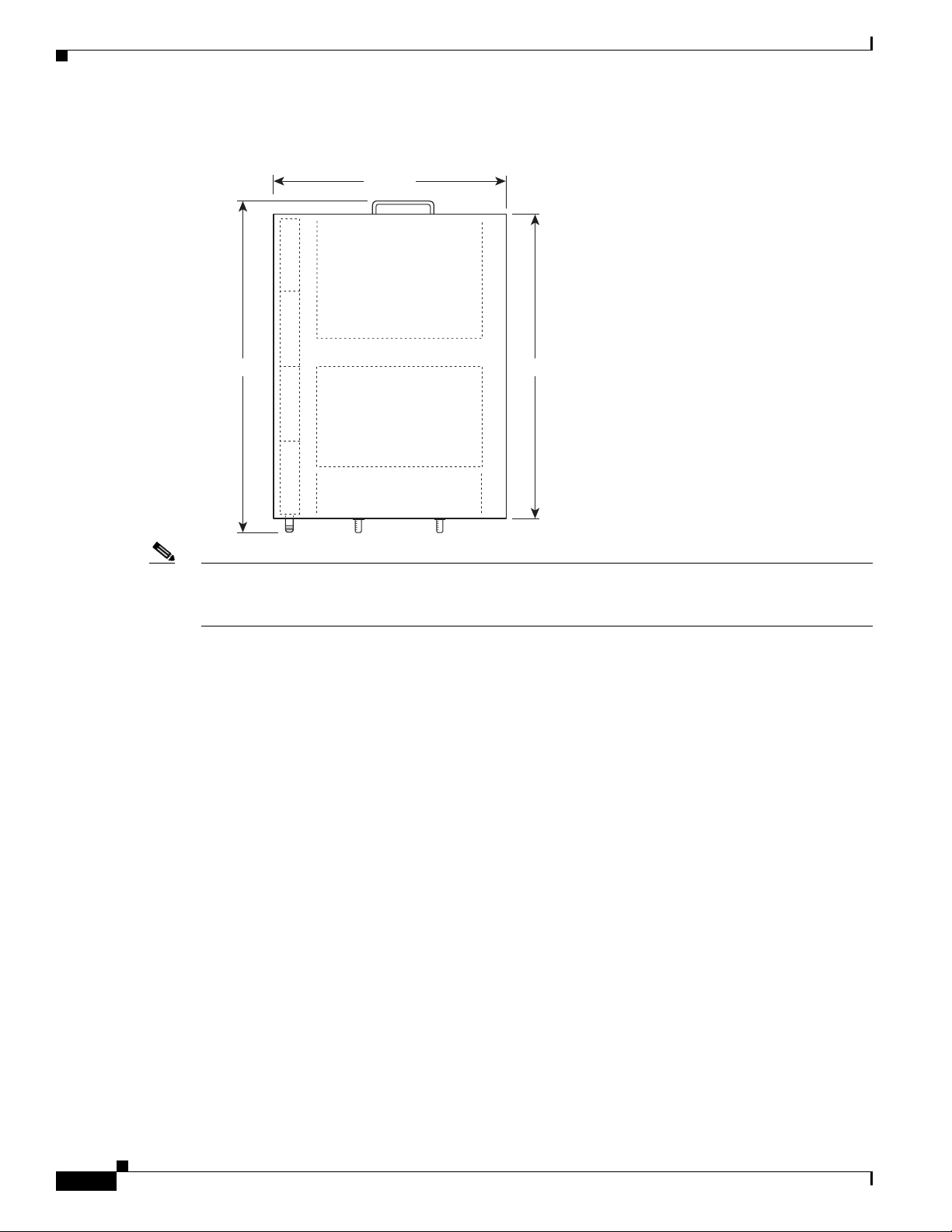
Provisioning the Cable Headend
Figure 2-3 Cisco uBR7225VXR Router Footprint and Outer Dimensions (View from Top Looking
Chapter 2 Preparing the Cisco uBR7225VXR Router for Installation
Down)
17.32 in.
23.875 in.
Note We recommend the rear bracket mounting system for four-post racks because this method enables you
21.875 in.
271658
to keep cables from protruding too far out in front of the Cisco uBR7225VXR router, and simultaneously
manage the cables at the front of the chassis with the cable-management bracket.
When planning your rack installation, consider the following information:
• Install the Cisco uBR7225VXR router in an open rack whenever possible. If installation in an
enclosed rack is unavoidable, ensure that the rack has adequate ventilation.
• If you plan to use an equipment shelf, ensure that the shelf is constructed to support the weight and
dimensions of the chassis. Figure 2-3 shows the chassis footprint, which you will need if you are
designing a customized shelf. We recommend that you use the rack-mount kit for the
Cisco uBR7225VXR router (product number ACS-uBR7225-RMK=).
• Allow sufficient clearance around the rack for maintenance. If the rack is mobile, you can push it
back near a wall or cabinet for normal operation and pull it out for maintenance (connecting cables,
or replacing or upgrading components). Otherwise, allow at least 23.25 inches (59.06 cm) of
clearance at the front, and 19 inches (48.3 cm) at the back to remove any of the field-replaceable
units.
• Maintain a minimum clearance of 3 inches (7.72 cm) on the right and left of the chassis for the
cooling air inlet and exhaust ports, respectively. Avoid placing the Cisco uBR7225VXR router in an
overly congested rack or directly next to another equipment rack; otherwise, the heated exhaust air
from other equipment can enter the inlet air vents and cause an overtemperature condition inside the
router.
• Always install heavier equipment in the lower half of a rack to maintain a low center of gravity and
prevent the rack from falling.
2-16
• If you use telco-type racks, be sure that the rack is bolted to the floor and secured, because in these
types of installations, only one end of the chassis mounts to the two rack posts with the brackets.
Ensure that the weight of the chassis does not make the rack unstable.
Cisco uBR7225VXR Universal Broadband Router Hardware Installation Guide
OL-17309-02
Page 49

Chapter 2 Preparing the Cisco uBR7225VXR Router for Installation
• Install and use the cable-management bracket included with the Cisco uBR7225VXR rack-mount
kit to keep cables organized. Consider the equipment and cabling that is already installed in the rack.
Ensure that cables from other equipment will not impair access to the interface slots, or require you
to disconnect cables unnecessarily to perform equipment maintenance or upgrades.
In addition to the preceding guidelines, review the precautions for avoiding overtemperature conditions
in the “Site Environment” section on page 2-5. To properly install the Cisco uBR7225VXR router
chassis in a rack, refer to the instructions in the “Cisco uBR7225VXR Router Chassis Rack-Mounting
Options” section on page 3-2.
Site Preparation Checklist
Caution Do not install the Cisco uBR7225VXR chassis in an enclosed rack or room that is not properly ventilated
or air-conditioned. The Cisco uBR7225VXR chassis overheats if the input air temperature reaches 105
(41oC).
Site Preparation Checklist
Before installing the Cisco uBR7225VXR router, assemble the equipment needed to support your
network configuration and subscriber service offering. Ensure all power and cabling requirements are
met based on the equipment to be installed. Also ensure that environmental conditions are met to
maintain proper equipment operation.
Table 2-2 is a checklist that identifies the key tasks to complete.
Table 2-2 Site Preparation Checklist
Task Verified By Date
General:
Safety recommendations and guidelines reviewed.
Required general CMTS preparations completed.
Site power voltages verified.
Site environmental specifications verified.
Downstream and upstream channel plans created.
Cable plant balanced, swept and verified to comply with DOCSIS or EuroDOCSIS
recommendations.
Optical receivers adjusted for proper upstream RF output levels.
Required passwords, IP addresses, device names available.
All additional CMTS equipment to support Internet access services, RF-related
equipment, servers and other host computers, a Cisco uBR900 series cable access router,
and console accessory kit to test operation of your network available.
Required tools and cables available.
Telco Return Configurations:
Telco return dial-up plan created.
Network access server installed and configured.
Telephone circuits, connections, and all equipment to support telco return available.
IP Telephony Configurations:
o
F
OL-17309-02
Cisco uBR7225VXR Universal Broadband Router Hardware Installation Guide
2-17
Page 50

Chapter 2 Preparing the Cisco uBR7225VXR Router for Installation
Component Checklists
Table 2-2 Site Preparation Checklist (continued)
Task Verified By Date
Gatekeeper and gateway equipment installed and configured.
Dial plan based on the supported VoIP protocol used—H.323 or SGCP.
Component Checklists
• Check off the equipment as it is unpacked.
• Titles and quantities of documents will vary.
Table 2-3 provides the list to verify the contents of the shipping container for the Cisco uBR7225VXR
router.
Table 2-3 Cisco uBR7225VXR Router Component List
Description Received
• Cisco uBR7225VXR chassis
• Network processing engine
• Up to two AC-input power supplies and power cords (blank power supply filler plate should be
installed in empty power supply slot)
• Up to two cable interface line cards (blank cable interface line cards should be installed in empty
cable interface line card slots)
• CompactFlash Disk
The following accessories might arrive in separate shipping containers:
• Rack-mount and cable-management kit—Two rack-mount brackets, cable-management bracket,
eight M4 x 6-mm Phillips flathead screws, four M3 x 6-mm Phillips panhead screws, and four
10/32 x 3/8-inch slotted binderhead screws
• AC-input power cables—Up to two AC-input power cables (if separate AC-input power supply
ordered)
• Documentation, including the following:
–
Cisco Information Packet
–
Cisco Network Registrar documentation—if ordered
–
Cisco IOS software documentation set—if ordered
Note All hardware and software documentation is also found at the following URL:
http://www.cisco.com/en/US/products/hw/cable/ps2217/tsd_products_support_series_home.ht
ml
2-18
Cisco uBR7225VXR Universal Broadband Router Hardware Installation Guide
OL-17309-02
Page 51

CHAP T E R
3
Installing the Cisco uBR7225VXR Router
This chapter explains how to install and connect a Cisco uBR7225VXR universal broadband router and
contains the following sections:
• Cisco uBR7225VXR Router Installation Checklist, page 3-1
• Cisco uBR7225VXR Router Chassis Rack-Mounting Options, page 3-2
• Installing the Brackets on the Chassis, page 3-7
• Installing the Chassis in a Workbench or Tabletop Environment, page 3-12
• Cabling, page 3-13
• Console and Auxiliary Port Connection Equipment, page 3-14
• Protective Grounding, page 3-16
• Connecting Power, page 3-16
• Powering On the Cisco uBR7225VXR Router, page 3-18
Cisco uBR7225VXR Router Installation Checklist
A rack-mount and cable-management kit is included in the shipping container. The rack-mount brackets
in the kit are for mounting the Cisco uBR7225VXR in standard, 19-inch-wide, 4-post equipment racks
or telco-type equipment racks. The rack-mount brackets are not suitable for use with other racks, such
as 23-inch telco racks. The cable-management bracket is designed to relieve the strain on interface cables
that are installed on cable interface line cards in a Cisco uBR7225VXR router.
If you are installing an equipment shelf or using mounting hardware other than that supplied with the
chassis, review the guidelines in the “Equipment Racks” section on page 2-15, then proceed to the
“Cisco uBR7225VXR Router Chassis Rack-Mounting Options” section on page 3-2.
If you do not plan to install your Cisco uBR7225VXR router in an equipment rack, proceed to the
“Installing the Chassis in a Workbench or Tabletop Environment” section on page 3-12.
To assist you with your installation and to provide a historical record of what was done, and by whom,
use “Cisco uBR7225VXR Router Installation Checklist” section on page 2. Make a copy of this
checklist and indicate when each procedure or verification is completed. When the checklist is
completed, place it in your site log (see Appendix G, “Site Log”) along with the other records for your
new router.
Cisco uBR7225VXR Universal Broadband Router Hardware Installation Guide
OL-17309-02
3-1
Page 52

Chapter 3 Installing the Cisco uBR7225VXR Router
Cisco uBR7225VXR Router Chassis Rack-Mounting Options
Table 3-1 Cisco uBR7225VXR Router Installation Checklist
Task Verified by Date
Router and all accessories unpacked
Types and numbers of interfaces verified
Verify shipping container contents see the “Shipping Container Contents” section
on page 2-9
Router mounted in rack (optional)
Cable-management bracket installed (optional but recommended)
Chassis properly grounded
AC power cables connected to power sources and router; cables secured
Captive installation screws on network processing engine checked
Network interface cables and devices connected
ASCII terminal attached to console port
Console port set for 9600 baud, 8 data bits, no parity, and 1 stop bit (9600 8N1)
System power turned on (Input OK LED is on)
System boot complete
Network processing engine and all cable interface line cards operational
System ready for global and interface-specific configuration
Cisco uBR7225VXR Router Chassis Rack-Mounting Options
The chassis mounts to two rack posts with brackets that attach to either the front, middle, or rear sides
of the chassis. The inside width between the posts or mounting strips (left and right) must be at least
17.5 inches (44.45 cm).
Some equipment racks provide a power strip along the length of one of the mounting strips. Figure 3-1
shows a typical 4-post equipment rack with a power strip along one of the back posts. If your rack has
this feature, consider the position of the strip when planning fastener points and ensure that you will be
able to pull cable interface line card cables and other FRUs straight out of their respective slots.
The inlet and exhaust ports for cooling air are located on the right and left of the chassis, respectively,
so multiple universal broadband routers can be stacked in a rack with little or no vertical clearance.
Note We recommend the rear bracket mounting system for 4-post racks. This method enables you to keep
cables from protruding too far out in front of the Cisco uBR7225VXR router and to simultaneously
manage the cables at the front of the chassis with the cable-management bracket.
3-2
Cisco uBR7225VXR Universal Broadband Router Hardware Installation Guide
OL-17309-02
Page 53

Chapter 3 Installing the Cisco uBR7225VXR Router
18.31 in.
(46.48 cm)
hole
center-to-center
17.5 in.
(44.45 cm)
min.
Rack posts
Mounting strips
110 VAC
outlets
10327
Figure 3-1 Typical 4-Post Equipment Rack Posts and Mounting Strips
Cisco uBR7225VXR Router Chassis Rack-Mounting Options
Mounting options are as follows:
• If you want the cable interface line card end (the front) of the chassis recessed in the rack, install
the rack-mount brackets at the rear of the chassis in the orientation shown in Figure 3-2 on page 3-4.
• If you want the front of the chassis mounted flush with the front posts of the rack, install the
rack-mount brackets at the front of the chassis in the orientation shown in Figure 3-3 on page 3-4.
• If you want the front of the chassis protruding out of the rack, install the rack-mount brackets at the
front of the chassis in the orientation shown in Figure 3-4 on page 3-5.
• If you want the chassis in a telco-type rack, install the rack-mount brackets in the middle of the
chassis in the orientation shown in Figure 3-5 on page 3-5.
OL-17309-02
Cisco uBR7225VXR Universal Broadband Router Hardware Installation Guide
3-3
Page 54
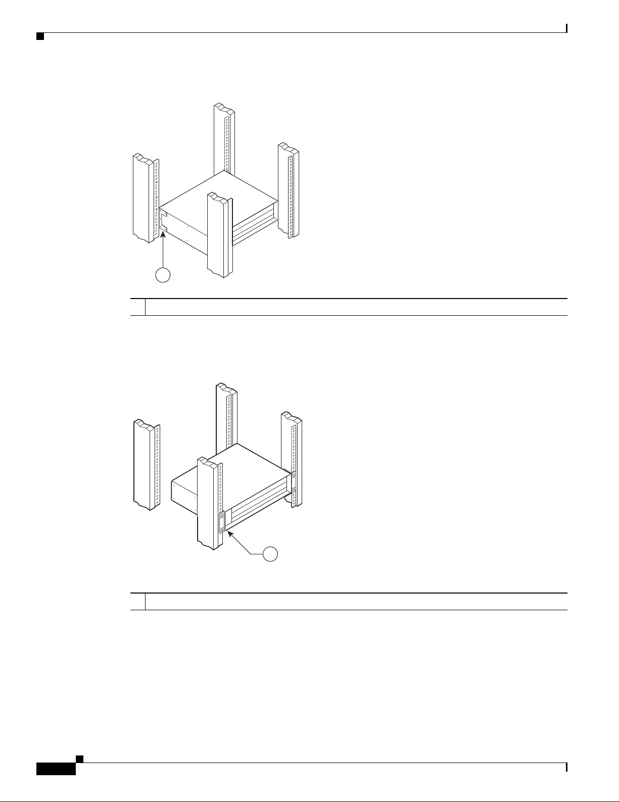
Cisco uBR7225VXR Router Chassis Rack-Mounting Options
271660
1
Figure 3-2 Installing the Chassis in a 4-Post Rack—Rear Installation
1
Rack-mount bracket
1
Chapter 3 Installing the Cisco uBR7225VXR Router
271659
See the “Installing Rack-Mount Brackets on the Rear of the Chassis” section on page 3-7.
Figure 3-3 Installing the Chassis in a 4-Post Rack—Flush-Mounted Front Installation
Rack-mount bracket
1
3-4
See the “Installing Rack-Mount Brackets on the Front of the Chassis” section on page 3-8 for bracket
mounting information.
Cisco uBR7225VXR Universal Broadband Router Hardware Installation Guide
OL-17309-02
Page 55
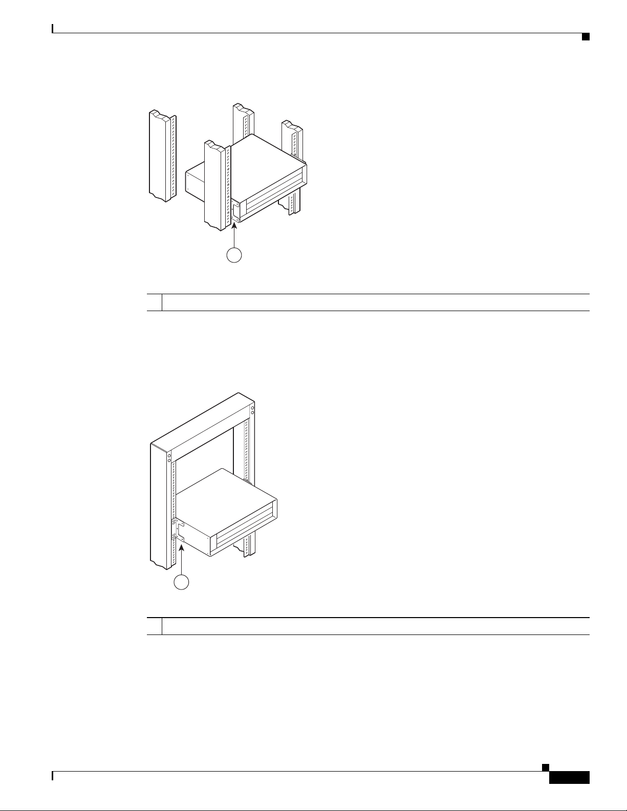
Chapter 3 Installing the Cisco uBR7225VXR Router
Cisco uBR7225VXR Router Chassis Rack-Mounting Options
Figure 3-4 Installing the Chassis in a 4-Post Rack—Chassis Protruding Front Installation
271661
1
Rack-mount bracket
1
See the “Installing Rack-Mount Brackets in the Middle of the Chassis” section on page 3-9 for bracket
mounting information.
Figure 3-5 Installing the Chassis in a Telco-Type Rack
271662
1
Rack-mount bracket
1
Cable-Management Bracket Requirements
There are two cable-management bracket configurations available for rack-mounting the
Cisco uBR7225VXR router. In the first configuration, for a 4-post rack, the rack-mount brackets are
installed at the rear of the chassis and the cable-management bracket is installed at the right front of the
chassis. (See Figure 3-6.) You must install both sets of brackets before you install the chassis in the rack.
Cisco uBR7225VXR Universal Broadband Router Hardware Installation Guide
OL-17309-02
3-5
Page 56

Cisco uBR7225VXR Router Chassis Rack-Mounting Options
In the second configuration, for a telco-type rack, the rack-mount brackets are installed at the middle of
the chassis and the cable-management bracket is installed at the right front of the chassis. (See
Figure 3-7.) You must install both sets of brackets before you install the chassis in the rack.
Chapter 3 Installing the Cisco uBR7225VXR Router
Figure 3-6 Installing the Chassis in a 4-Post Rack with an Installed Cable-Management Bracket
271663
1
Rack-mount bracket
1
Figure 3-7 Installing the Chassis in a Telco-Type Rack with an Installed Cable-Management
Bracket
2
Cable-management bracket
2
3-6
2
1
Rack-mount bracket
1
Cisco uBR7225VXR Universal Broadband Router Hardware Installation Guide
271664
Cable-management bracket
2
OL-17309-02
Page 57
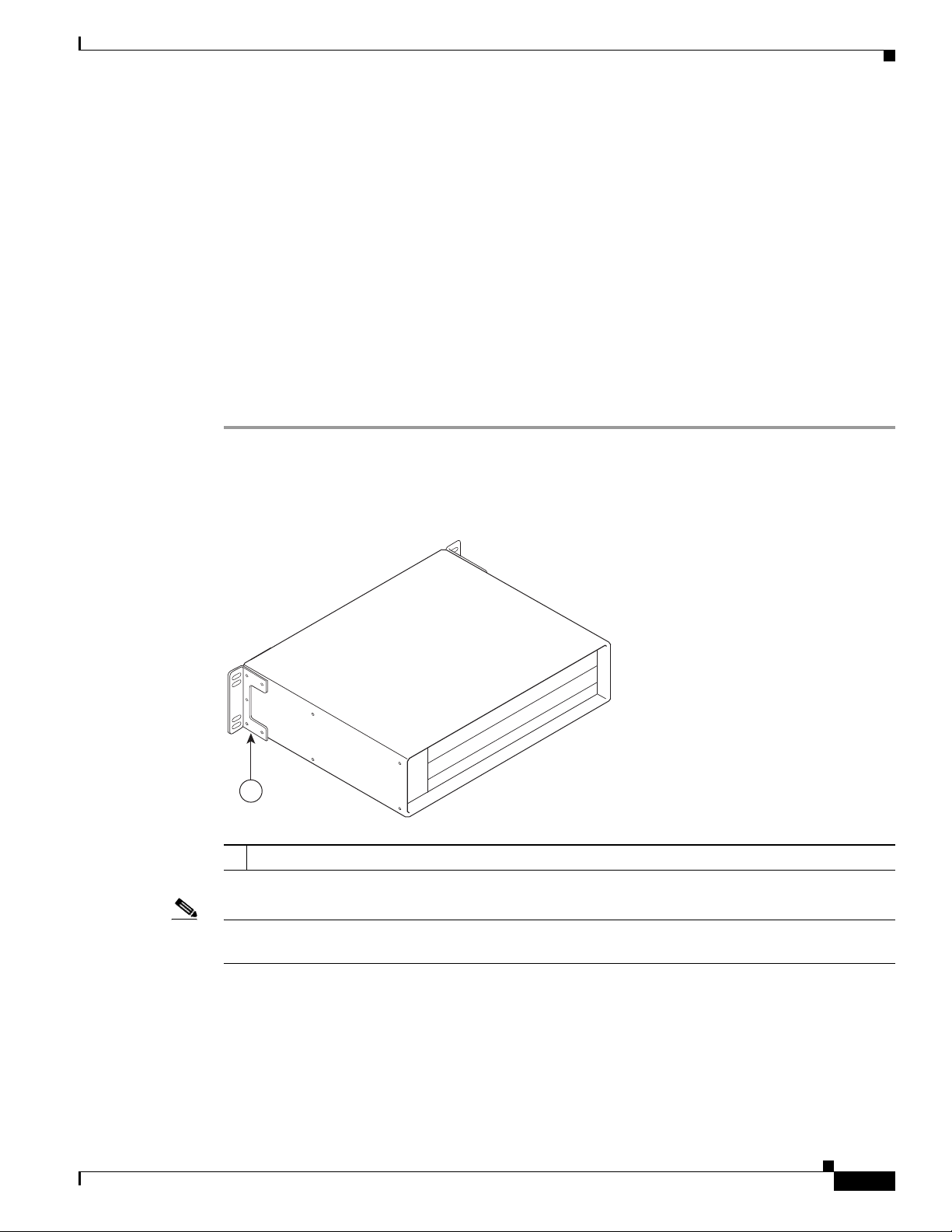
Chapter 3 Installing the Cisco uBR7225VXR Router
Installing the Brackets on the Chassis
This section explains how to install the rack-mount brackets and cable-management bracket on a
Cisco uBR7225VXR universal broadband router. Before installing the chassis in the rack, you must
install cable-management bracket and a rack-mount bracket on each side of the front, middle, or rear of
the chassis.
The parts and tools required for installing the rack-mount and cable-management bracket are listed in
the “Installation Tools” section on page 2-8.
Installing Rack-Mount Brackets on the Rear of the Chassis
To install the rack-mount brackets and cable-management bracket on the chassis for a rear rack-mount
configuration, complete the following steps:
Step 1 Locate the threaded holes in the rear sides of the chassis.
Step 2 Align the first rack-mount bracket to the threaded holes in the right side of the chassis. See Figure 3-8.
Installing the Brackets on the Chassis
Figure 3-8 Installing the Rack-Mount Brackets on the Rear of the Chassis
271665
1
Rack-mount bracket
1
Note There are five holes in each of the rack-mount brackets for the Cisco uBR7225VXR router. Four holes
are used for front and middle mount, and five holes are used for rear mount.
OL-17309-02
Step 3 Thread five M4 x 6-mm Phillips flathead screws through the rack-mount bracket and into the side of the
chassis. Use a number 2 Phillips screwdriver to tighten the screws.
Step 4 Repeat Step 1 through Step 3 for the other rack-mount bracket.
Step 5 If you plan to include the cable-management bracket in your rear rack-mount configuration, align the
bracket with the two right front-side holes.
Cisco uBR7225VXR Universal Broadband Router Hardware Installation Guide
3-7
Page 58

Chapter 3 Installing the Cisco uBR7225VXR Router
Installing the Brackets on the Chassis
Step 6 Thread two M3 x 6-mm Phillips panhead screws through the cable-management bracket and into the
chassis, and tighten the screws.
This completes the procedure for installing the rack-mount brackets and the cable-management bracket
on the chassis for a rear rack-mount configuration. Proceed to the “Installing the Chassis in the Rack”
section on page 3-10.
Caution To prevent injury, review the safety precautions in Chapter 2, “Preparing the Cisco uBR7225VXR
Router for Installation,” before installing the Cisco uBR7225VXR router in a rack.
Installing Rack-Mount Brackets on the Front of the Chassis
To install the rack-mount brackets and cable-management bracket on the chassis for a front rack-mount
configuration, complete the following steps:
Step 1 Locate the threaded holes in the front sides of the chassis.
Step 2 If you want the front of the chassis flush with the front of the rack, align the first rack-mount bracket to
the threaded holes in the right side of the chassis as shown in Figure 3-9 on page 3-8.
If you want the front of the chassis protruding from the rack, align the first rack-mount bracket to the
threaded holes in the right side of the chassis as shown in Figure 3-10 on page 3-9.
Note There are five holes in each of the rack-mount brackets for the Cisco uBR7225VXR. Four holes are used
for front and middle mount, and five holes are used for rear mount.
Figure 3-9 Installing the Rack-Mount Brackets so the Front of the Chassis Is Flush with the Rack
271666
3-8
1
Rack-mount bracket
1
Cisco uBR7225VXR Universal Broadband Router Hardware Installation Guide
OL-17309-02
Page 59

Chapter 3 Installing the Cisco uBR7225VXR Router
271667
1
Figure 3-10 Installing the Rack-Mount Brackets so the Front of the Chassis Protrudes Out of the
Rack
Rack-mount bracket
1
Installing the Brackets on the Chassis
Step 3 Thread four M4 x 6-mm Phillips flathead screws through the rack-mount bracket and into the side of the
chassis. Use a number 2 Phillips screwdriver to tighten the screws.
Step 4 Repeat Step 1 through Step 3 for the other rack-mount bracket.
Step 5 If you plan to include the cable-management bracket in your front rack-mount configuration, align the
bracket with the two right front-side holes.
Step 6 Thread two M3 x 6-mm Phillips panhead screws through the cable-management bracket and into the
chassis, and tighten the screws.
This completes the procedure for installing the rack-mount brackets on the chassis for a front rack-mount
configuration. Proceed to the “Installing the Chassis in the Rack” section on page 3-10.
Caution To prevent injury, review the safety precautions in Chapter 2, “Preparing the Cisco uBR7225VXR
Router for Installation,” before installing the universal broadband router in a rack.
Installing Rack-Mount Brackets in the Middle of the Chassis
To install the rack-mount brackets and cable-management bracket at the middle of the chassis for a
telco-type rack-mount configuration, complete the following steps:
OL-17309-02
Step 1 Locate the threaded holes in the middle sides of the chassis.
Step 2 Align the first rack-mount bracket to the threaded holes in the right side of the chassis. See Figure 3-11.
Note There are five holes in each of the rack-mount brackets for the Cisco uBR7225VXR router. Four holes
are used for front and middle mount, and five holes are used for rear mount.
Cisco uBR7225VXR Universal Broadband Router Hardware Installation Guide
3-9
Page 60
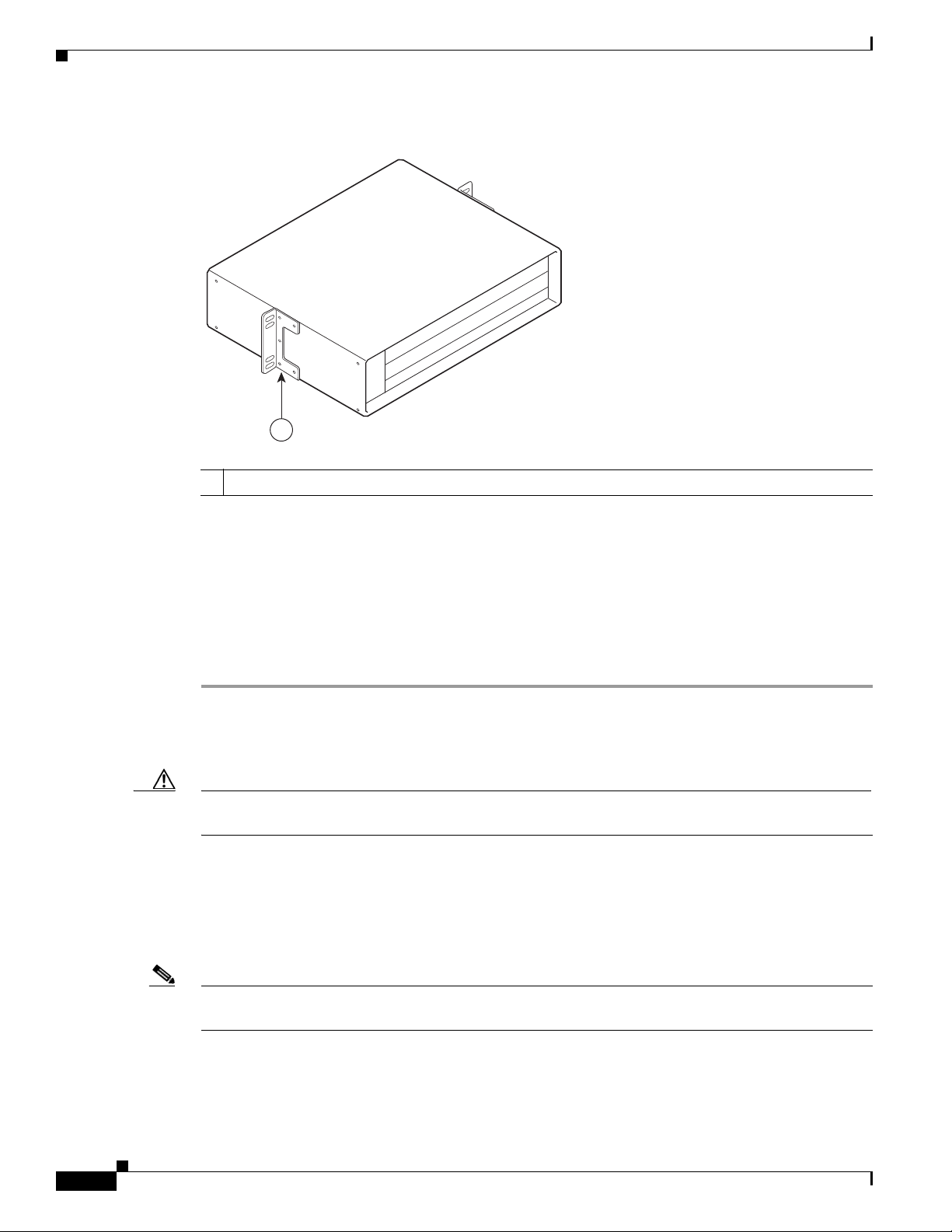
Installing the Brackets on the Chassis
271668
1
Figure 3-11 Installing the Rack-Mount Brackets in the Middle of the Chassis for Telco-Type Racks
Rack-mount bracket
1
Chapter 3 Installing the Cisco uBR7225VXR Router
Step 3 Thread four M4 x 6-mm Phillips flathead screws through the rack-mount bracket and into the side of the
chassis. Use a number 2 Phillips screwdriver to tighten the screws.
Step 4 Repeat Step 1 through Step 3 for the other rack-mount bracket.
Step 5 If you plan to include the cable-management bracket in your telco-type rack-mount configuration, align
the bracket with the right front-side holes.
Step 6 Thread two M3 x 6-mm Phillips panhead screws through the cable-management bracket and into the
chassis, and tighten the screws.
This completes the procedure for installing the rack-mount brackets and cable-management bracket on
the Cisco uBR7225VXR router. Proceed to the following section, “Installing the Chassis in the Rack.”
Caution To prevent injury, review the safety precautions in Chapter 2, “Preparing the Cisco uBR7225VXR
Router for Installation,” before installing the Cisco uBR7225VXR router in a rack.
Installing the Chassis in the Rack
After installing the brackets on the chassis, mount the chassis by securing the rack-mount brackets to the
posts or mounting strips in the rack using the slotted screws provided.
3-10
Note When installing the uBR7225VXR in a rack, ensure that paint is removed from the rack and an
anti-oxidant is applied at the contact points to ensure reliable metal to metal contact.
Cisco uBR7225VXR Universal Broadband Router Hardware Installation Guide
OL-17309-02
Page 61

Chapter 3 Installing the Cisco uBR7225VXR Router
Caution Because the brackets support the weight of the entire chassis, be sure to use all of the required slotted
screws to fasten the two rack-mount brackets to the rack posts. Figure 3-2 on page 3-4, Figure 3-3 on
page 3-4, Figure 3-4 on page 3-5, and Figure 3-5 on page 3-5 show typical installations in 19-inch,
four-post and telco-type equipment racks.
Installing the Brackets on the Chassis
Warning
Two people are required to lift the chassis. Grasp the chassis underneath the lower edge and lift with
both hands. To prevent injury, keep your back straight and lift with your legs, not your back. To prevent
damage to the chassis and components, never attempt to lift the chassis with the handles on the
power supplies or on the interface processors, or by the plastic panels on the front of the chassis.
Warning
These handles were not designed to support the weight of the chassis.
To prevent bodily injury when mounting or servicing this unit in a rack, you must take special
Statement 5
precautions to ensure that the system remains stable. The following guidelines are provided to
ensure your safety:
• This unit should be mounted at the bottom of the rack if it is the only unit in the rack.
• When mounting this unit in a partially filled rack, load the rack from the bottom to the top with
Statement 1006
the heaviest component at the bottom of the rack.
• If the rack is provided with stabilizing devices, install the stabilizers before mounting or servicing
the unit in the rack.
To install the chassis in the rack, complete the following steps:
Step 1 On the chassis, ensure that all captive installation screws on the network processing engine, each
cable interface line card, and each power supply are tightened.
Step 2 Make sure that your path to the rack is unobstructed. If the rack is on wheels, ensure that the brakes are
engaged or that the rack is otherwise stabilized.
OL-17309-02
Caution Two people should perform Step 3 through Step 6.
Step 3 Position the chassis so that the front end is closest to you; then lift the chassis and move it to the rack.
To prevent injury, avoid sudden twists or moves.
Step 4 Slide the chassis into the rack, pushing it back until the brackets (installed at the front or rear of the
chassis) meet the mounting strips or posts on both sides of the equipment rack.
Note The rack-mount bracket must be placed behind the rack post or mounting strip in the rear installation
configuration. (See Figure 3-2 on page 3-4.)
Step 5 While keeping the brackets flush against the posts or mounting strips, position the router so that the holes
in the brackets are aligned with those in the mounting strips.
Cisco uBR7225VXR Universal Broadband Router Hardware Installation Guide
3-11
Page 62

Chapter 3 Installing the Cisco uBR7225VXR Router
Installing the Chassis in a Workbench or Tabletop Environment
Step 6 Insert the 10/32 x 3/8 slotted screws (two to a side) through the brackets and into the mounting strip (use
the top and bottom bracket holes, shown in Figure 3-2 on page 3-4, Figure 3-3 on page 3-4, Figure 3-4
on page 3-5, and Figure 3-5 on page 3-5). Using a 7/16-inch flat-blade screwdriver, tighten all the
screws.
This completes the procedure for installing the chassis in the rack. Proceed to the “Cabling” section on
page 3-13 to continue the installation.
Installing the Chassis in a Workbench or Tabletop Environment
The Cisco uBR7225VXR universal broadband router should already be in the area where you will install
it, and your installation location should already be determined. If not, refer to the “Site Requirements”
section on page 2-5.
When installing the router on a workbench or tabletop, ensure that the surface is clean and in a safe
location and that you have considered the following:
• The Cisco uBR7225VXR router requires at least 3 inches (7.72 cm) of clearance at the inlet and
exhaust vents (the right and left sides of the router).
• The Cisco uBR7225VXR router should be installed off the floor. (Dust that accumulates on the floor
can be drawn into the interior of the router by the cooling fans. Excessive dust inside the router can
cause overtemperature conditions and component failures.)
• There must be approximately 23.25 inches (59.06 cm) of clearance at the front, and 19 inches
(48.3 cm) at the back of the Cisco uBR7225VXR router for installing and replacing
field-replaceable units (FRUs), or accessing network cables or equipment.
• Make sure that blank cable interface line card and blank power supply filler plates are installed in
empty slots.
• The Cisco uBR7225VXR router will receive adequate ventilation (it is being installed in an enclosed
cabinet where ventilation is adequate).
• If you plan to install the cable-management bracket on the front of the chassis, set aside the
cable-management bracket and the four M3 x 6-mm Phillips panhead screws.
Warning
Do not stack the chassis on any other equipment. If the chassis falls, it can cause severe bodily injury
and equipment damage.
Statement 48
Complete the following steps to install the Cisco uBR7225VXR router on a workbench or tabletop:
Step 1 Remove any debris and dust from the tabletop or workbench, and the surrounding area. Also make sure
that your path between the router and its new location is unobstructed.
Step 2 On the chassis, ensure that all captive installation screws on the network processing engine, cable
interface line cards, and each power supply are tightened.
Warning
Two people are required to lift the chassis. To prevent injury, keep your back straight and lift with your
legs, not your back.
Statement 164
3-12
Cisco uBR7225VXR Universal Broadband Router Hardware Installation Guide
OL-17309-02
Page 63

Chapter 3 Installing the Cisco uBR7225VXR Router
Cabling
Step 3 Add the five rubber feet supplied with the accessory kit to the base of the chassis. Five indented circles
are provided on the base of the chassis to indicate the location to which the rubber feet can be added.
Step 4 Place the Cisco uBR7225VXR router on the tabletop or workbench.
Step 5 Ensure that there is the appropriate amount of space around the router.
If you want to install a cable-management bracket on the Cisco uBR7225VXR router, proceed to the
following section, “Installing the Cable-Management Bracket on a Cisco uBR7225VXR Router in a
Workbench or Tabletop Environment.” Otherwise, proceed to the “Cabling” section on page 3-13.
Installing the Cable-Management Bracket on a Cisco uBR7225VXR Router in a Workbench or Tabletop Environment
To install the cable-management bracket on a Cisco uBR7225VXR universal broadband router installed
on a workbench or tabletop, complete the following steps:
Step 1 Locate the threaded holes in the right front side of the chassis.
Step 2 Align the cable-management bracket with the two threaded holes on the front or rear side of the
Step 3 Thread two M3 x 6-mm Phillips panhead screws through the bracket and into the chassis. Use a number
Cabling
Warning
Cisco uBR7225VXR chassis. (See Figure 3-7 on page 3-6.)
2 Phillips screwdriver to tighten the screws.
This completes the steps for installing the cable-management bracket on the Cisco uBR7225VXR router.
Proceed to, “Cabling” section on page 3-13 to continue the installation.
This section provides information on connecting cable interface cards, auxiliary and console ports to
your Cisco uBR7225VXR universal broadband router.
This product is not intended to be directly connected to the Cable Distribution System. Additional
regulatory compliance and legal requirements may apply for direct connection to the Cable
Distribution System. This product may connect to the Cable Distribution System ONLY through a device
that is approved for direct connection.
Statement 1078
OL-17309-02
Warning
The intra-building port(s) of the equipment or subassembly is suitable for connection to intra-building
or unexposed wiring or cabling only. The intra-building port(s) of the equipment or subassembly
MUST NOT metallically connect to interfaces that connect to the OSP or its wiring. These interfaces
are designed for use as intra-building interfaces only (Type 2 or Type 4 ports as described in
GR-1089-CORE, Issue 4) and require isolation from the exposed OSP cabling. The addition of Primary
Protectors is not sufficient protection in order to connect these interfaces metallically to OSP wiring.
Statement 7005
Cisco uBR7225VXR Universal Broadband Router Hardware Installation Guide
3-13
Page 64
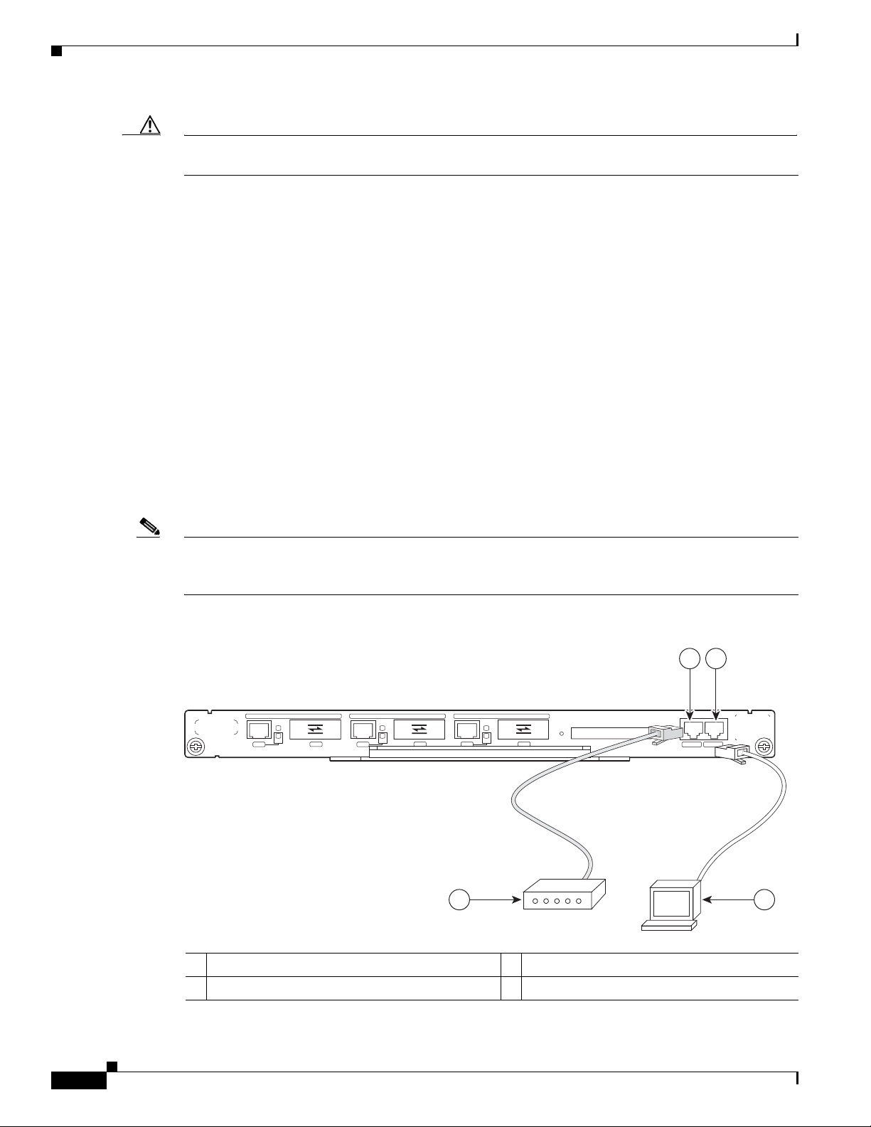
Chapter 3 Installing the Cisco uBR7225VXR Router
Console and Auxiliary Port Connection Equipment
Caution To comply with GR-1089-Core intra-building lightning-immunity requirements, you must use shielded
(screened) cable that is grounded at both ends.
Connecting Cable Interface Line Card Cables
The instructions for connecting the cables for each cable interface line card installed in the
Cisco uBR7225VXR universal broadband router are contained in the cable interface line card
installation document. Refer to the Cisco uBR7200 Series Interface Line Card Hardware Installation
Guide at the following URL:
http://www.cisco.com/en/US/docs/interfaces_modules/cable/line_cards/installation/guide/mcxxfru.htm
l
Console and Auxiliary Port Connection Equipment
The NPE contains the console and auxiliary ports. The console port is a RJ-45 receptacle for connecting
a data terminal, which you use to configure the interfaces and bring up the Cisco uBR7255VXR router.
The auxiliary port is a RJ-45 receptable for connecting a modem or the other DCE device (such as a
channel service unit/data service unit [CSU/DSU]) to the router. (See Figure 3-12 on page 3-14.)
Note Both the console and auxiliary ports are asynchronous ports; any devices connected to these ports must
be capable of asynchronous transmission. (Asynchronous is the most common type of serial device; for
example, most modems are asynchronous devices.)
Figure 3-12 Console and Auxiliary Port Connections
2
1
GIGABIT ETHERNET 0/1
LINK
EN
RX TX
RJ45 GBIC
GIGABIT ETHERNET 0/1
LINK
EN
RX TX
RJ45 GBIC
GIGABIT ETHERNET 0/1
LINK
EN
RX TX
RJ45 GBIC
4
NETWORK PROCESSING ENGINE - G1
CPU
RESET
COMPACT FLASH
SLOT
ACTIVE
POWER
ON
CONSOLE AUX
272232
3
3-14
Console port
1
Auxiliary port
2
Cisco uBR7225VXR Universal Broadband Router Hardware Installation Guide
Console terminal
3
Modem
4
OL-17309-02
Page 65

Chapter 3 Installing the Cisco uBR7225VXR Router
Before connecting a terminal to the console port, configure the terminal to match the
Cisco uBR7225VXR router console port as follows:
• 9600 baud
• 8 data bits
• No parity
• 1 stop bit (9600 8N1)
You need an RJ-45 console cable to connect the terminal to the console port. After you establish normal
universal broadband router operation, you can disconnect the terminal.
You must supply your own interface cable between the auxiliary port and the equipment you are
connecting. For console and auxiliary port pinouts, refer to the “Console Port Signals” section on
page 3-15 and the “Auxiliary Port Signals” section on page 3-15.
Console Port Signals
Both Data Set Ready (DSR) and Data Carrier Detect (DCD) signals are active when the system is
running. The Request To Send (RTS) signal tracks the state of the Clear To Send (CTS) input. The
console port does not support modem control or hardware flow control. Tab le 3-2 lists the signals used
on the console port. The console port requires a straight-through EIA/TIA-232 cable.
Console and Auxiliary Port Connection Equipment
Table 3-2 Console Port Signal
Pin Signal Direction Description
1 GND – Ground
2 TxD <— Transmit Data
3 RxD —> Receive Data
6 DSR —> Data Set Ready (always on)
7 GND – Ground
8 DCD —> Data Carrier Detect (always on)
Auxiliary Port Signals
Table 3-3 lists the signals used on the auxiliary port. The auxiliary port supports hardware flow control
and modem control.
Table 3-3 Auxiliary Port Signals
Pin Signal Direction Description
2 TxD —> Transmit Data
3 RxD <— Receive Data
4 RTS —> Request To Send (used for hardware flow control)
5 CTS <— Clear To Send (used for hardware flow control)
6 DSR <— Data Set Ready
7 Signal Ground – Signal Ground
OL-17309-02
Cisco uBR7225VXR Universal Broadband Router Hardware Installation Guide
3-15
Page 66

Protective Grounding
uBR7225-VXR
uBR7225-VXR
1
Table 3-3 Auxiliary Port Signals
Pin Signal Direction Description
8 CD <— Carrier Detect (used for modem control)
20 DTR —> Data Terminal Ready (used for modem control only)
Protective Grounding
The building installation should provide a means for connection to the protective earth grounding. The
equipment should be connected to that means.
Note The uBR7225VXR is intended for installation in a Common Bonding Network (CBN).
While installing the equipment, the service person should check whether the power source is adequately
grounded. If it is not, the service person should arrange for the installation of a protective grounding
conductor from the equipment to the protective grounding wire in the building. This conductor should
consist of a minimum #6 American Wire Gauge (AWG) stranded copper wire. See Figure 3-13 to
identify the ground lug location.
Chapter 3 Installing the Cisco uBR7225VXR Router
Figure 3-13 Cisco uBR7225VXR Ground Lug Location
Ground lug location
1
Connecting Power
Following are the procedures for connecting AC-input power to your Cisco uBR7225VXR universal
broadband router.
Warning
Warning
High leakage current - earth connection essential before connecting to system power supply.
Statement 342
Care must be given to connecting units to the supply circuit so that wiring is not overloaded.
1018
Statement
3-16
Warning
Cisco uBR7225VXR Universal Broadband Router Hardware Installation Guide
Read the installation instructions before you connect the system to its power source.
Statement 1004
OL-17309-02
Page 67

Chapter 3 Installing the Cisco uBR7225VXR Router
Connecting Power
Warning
Warning
Warning
Note Detailed instructions for handling and replacing the Cisco uBR7225VXR router power supplies are
Before working on equipment that is connected to power lines, remove jewelry (including rings,
necklaces, and watches). Metal objects will heat up when connected to power and ground and can
cause serious burns or weld the metal object to the terminals.
This equipment is intended to be grounded to comply with emission and immunity requirements.
Ensure that the switch functional ground lug is connected to earth ground during normal use.
Statement 1064
This equipment must be grounded. Never defeat the ground conductor or operate the equipment in the
absence of a suitably installed ground conductor. Contact the appropriate electrical inspection
authority or an electrician if you are uncertain that suitable grounding is available.
contained in the Cisco uBR7200 Series Universal Broadband Router AC-Input Power Supply
Replacement Instructions at the following URL:
http://www.cisco.com/en/US/docs/cable/cmts/ubr7200/installation/4848pwra.html
Connecting to the AC-Input Power Supply
Statement 43
Statement 1024
Warning
Note A certified external Surge Protective Device (SPD) is used at the AC-input of the Cisco uBR7225VXR
The device is designed to work with TN power systems.
Statement 19
universal broadband router.
To connect to the AC-input power supply:
Step 1 At the rear of the Cisco uBR7225VXR universal broadband router, ensure that the power switch on the
power supply is in the off (0) position.
Step 2 Plug in the power cable.
OL-17309-02
Cisco uBR7225VXR Universal Broadband Router Hardware Installation Guide
3-17
Page 68

Powering On the Cisco uBR7225VXR Router
271670
1
2
5
4
3
Figure 3-14 Connecting AC-Input Power
Chapter 3 Installing the Cisco uBR7225VXR Router
PWR-UBR7225VXR-AC
100-240 VAC
4-2 A
50-60 Hz
InputOKOutput
OK
Power switch
1
Handle
2
AC power cable
3
Step 3 Plug the AC power supply cable into the AC power source.
Step 4 Repeat Step 1 through Step 3 for the second power supply (if present).
Power receptacle
4
Captive installation screw
5
This completes the procedure for connecting AC-input power. Proceed to the “Powering On the
Cisco uBR7225VXR Router” section on page 3-18.
Powering On the Cisco uBR7225VXR Router
After installing your Cisco uBR7225VXR universal broadband router and connecting cables, power on
the universal broadband router as follows:
Step 1 Check for the following:
• Each cable interface line card is inserted in its slot and its captive installation screws are tightened.
• The network processing engine is inserted in to its slot and the captive installation screws are
tightened.
3-18
Cisco uBR7225VXR Universal Broadband Router Hardware Installation Guide
OL-17309-02
Page 69

Chapter 3 Installing the Cisco uBR7225VXR Router
Note If the cable interface line card or the network processing engine is not properly seated or not fully locked
into place, the Cisco uBR7225VXR router might enter a continuous restart loop. Make sure that the
boards are seated and locked into position.
• Hybrid fiber-coaxial (HFC) network coaxial cable is connected to the cable interface line cards.
• A CompactFlash Disk is installed in a CompactFlash Disk slot in the front panel of the NPE-G1 or
NPE-G2. Use only authorized Cisco provided CompactFlash Disks.
• Each AC-input power cable is connected.
• The console terminal is turned on.
Step 2 At the rear of the Cisco uBR7225VXR router, place the power switch on the power supply in the on (|)
position. Repeat this step if a second power supply is installed. The power supply OK LEDs comes on.
Step 3 Listen for the fans; you should immediately hear them operating. In a very noisy environment, also look
for air movement around the chassis to verify that the fans are operating. If the Cisco uBR7225VXR
router was recently switched off, it might take up to 90 seconds for the power supply to restart and the
fans to start operating.
Configuring the Interfaces
Note To facilitate headend installation, a Cisco uBR7225VXR universal broadband router equipped with at
least one cable interface line card generates a downstream IF carrier when it starts running.
The downstream IF carrier will be present if a cable interface line card is properly installed and passes
diagnostics, the router has been powered on for more than two minutes, the IF downstream shutdown
command (no cable downstream if-output) has not been configured, or the Cisco uBR7225VXR router
is not in ROMMON mode. The amplitude and shape of the downstream IF carrier will not change after
the Cisco uBR7225VXR router is configured, unless a non-DOCSIS data rate is configured.
Step 4 Observe the initialization process. When the system boot is complete (a few seconds), the network
processing engine begins to initialize the cable interface line cards. During this initialization, the LEDs
on each cable interface line card behave differently (most flash on and off). The enabled LED on each
cable interface line card goes on when initialization is complete, and the console screen displays a script
and system banner similar to the following:
Cisco IOS Software, 7200 Software (UBR7200-K9PU2-M), Version 12.2(33)SCA, RELEASE SOFTWARE
(fc1)
Technical Support: http://www.cisco.com/techsupport
Copyright (c) 1986-2008 by Cisco Systems, Inc.
Compiled Thu 14-Feb-08 13:58 by prod_rel_team
Configuring the Interfaces
OL-17309-02
When you start up the Cisco uBR7225VXR router for the first time, the system automatically enters the
setup facility (also called the system configuration dialog), which determines which cable interface
cards are installed. The setup facility prompts you for configuration information.
On the console terminal, after the system displays the system banner and hardware configuration, the
following System Configuration Dialog prompt appears:
--- System Configuration Dialog ---
Cisco uBR7225VXR Universal Broadband Router Hardware Installation Guide
3-19
Page 70

Configuring the Interfaces
Caution The setup facility currently excludes cable-specific configuration commands. Upstream ports, therefore,
Chapter 3 Installing the Cisco uBR7225VXR Router
At any point you may enter a questions mark ‘?’ for help.
Use ctrl-c to abort configuration dialof at any prompt.
Default settings are in square brackets ‘[]’.
continue with configuration dialog? [yes]:
You can proceed with the setup facility or exit from the setup facility, using the command interface to
configure global (system-wide) and interface-specific parameters.
have a default state of “shutdown” after the setup facility is run. You must configure upstream
parameters. For additional information, refer to the Cisco uBR7200 Series Software Configuration Guide
at the following URL:
http://www.cisco.com/en/US/docs/cable/cmts/ubr7200/configuration/guide/cr72scg.html
You do not have to configure the interfaces immediately; however, you cannot enable the interfaces or
connect them to any networks until you have configured them.
Many of the cable interface line card LEDs do not come on until you have configured the interfaces. To
verify correct operation of each interface, complete the first-time startup procedures and configuration,
then refer to the document for each cable interface line card for LED descriptions and to check the status
of the interfaces.
Your Cisco uBR7225VXR chassis installation is complete. To set up your cable network headend,
proceed to Chapter 4, “Connecting the Cisco uBR7225VXR Router to the Cable Headend.” To begin
configuring your Cisco uBR7225VXR router, see the Cisco uBR7200 Series Software Configuration
Guide at the following URL:
http://www.cisco.com/en/US/docs/cable/cmts/ubr7200/configuration/guide/cr72scg.html
3-20
Cisco uBR7225VXR Universal Broadband Router Hardware Installation Guide
OL-17309-02
Page 71

CHAP T E R
4
Connecting the Cisco uBR7225VXR Router to the Cable Headend
This chapter describes how to connect the Cisco uBR7225VXR universal broadband router to a cable
headend and contains the following sections:
• Two-Way Data Headend Architecture, page 4-2
• One-Way Data Headend Architecture, page 4-3
• RF and Digital Data Overview, page 4-3
• Connecting and Configuring the Downstream, page 4-4
• Measuring the Downstream RF Signal, page 4-4
• Connecting and Configuring the Upstream, page 4-18
• Measuring the Upstream RF Signal, page 4-22
• Measuring the RF Signal at the Forward Test Point on a Laser Transmitter, page 4-37
• Configuring the Digital Signal, page 4-40
OL-17309-02
Note Before installing your Cisco uBR7225VXR router, analyze the radio frequency (RF) setup at your
headend and configure the analog RF signals for interaction with digital data. This chapter guides you
through the process of configuring the RF and digital data at the headend for optimal performance.
Cisco uBR7225VXR Universal Broadband Router Hardware Installation Guide
4-1
Page 72
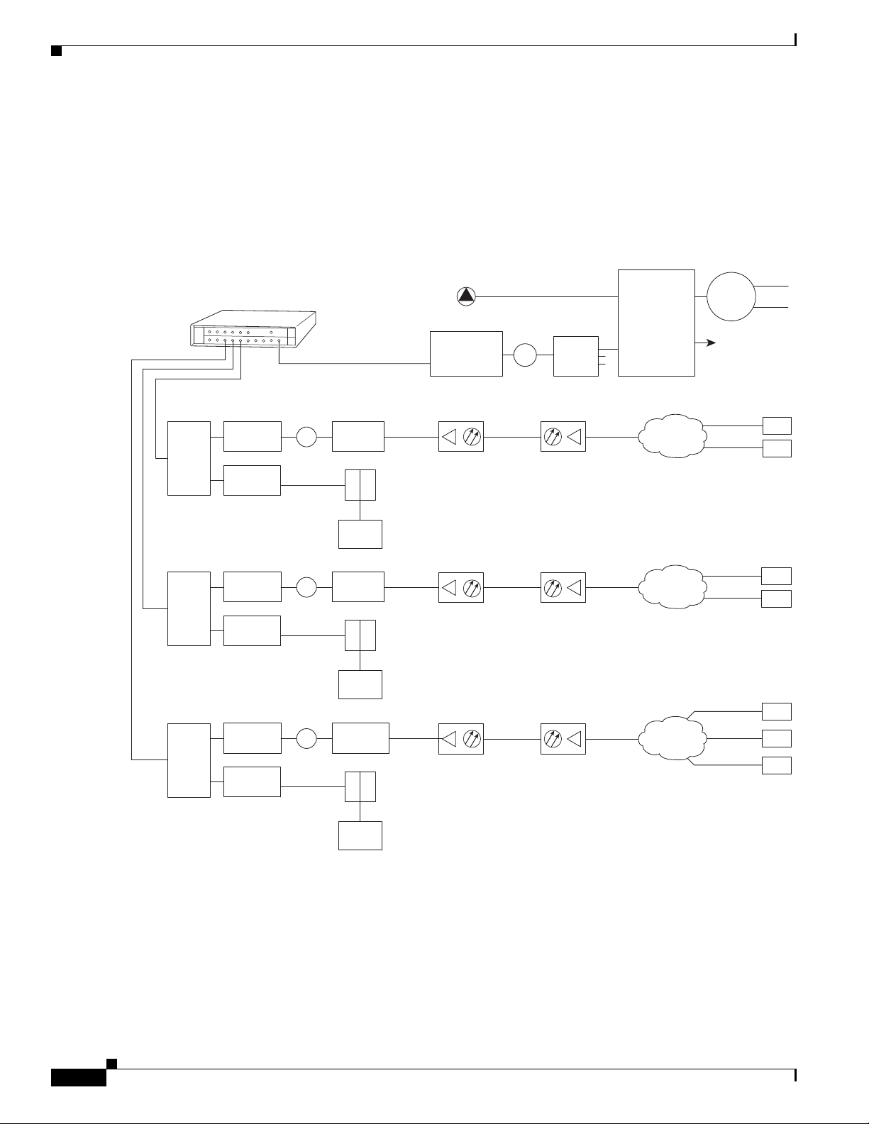
Chapter 4 Connecting the Cisco uBR7225VXR Router to the Cable Headend
Cisco
uBR7225VXR
Downstream
271671
Upstream
0 dBmV
6 dB
attenuator
40 dB
attenuator
3 dB
attenuator
Optical
receiver
Fiber-optic
cable
Distribution
network
+17 dBmV +13 dBmV
Cable
modems
+48 dBmV
+31 dBmV
2-way
splitter
+10 dBmV
6 dB
attenuator
40 dB
attenuator
8 dB
attenuator
+18 dBmV
+42 dBmV
+58 dBmV
2-way
splitter
+10 dBmV
6 dB
attenuator
40 dB
attenuator
21 dB
attenuator
+31 dBmV
+42 dBmV
+49 dBmV
+50 dBmV
2-way
splitter
+10 dBmV
Laser
transmitter
Broadcast
Narrowcast
0 to 20 dB
attenuator
(as required)
8-way
tap
3-way
splitter
+17 dBmV
video carrier
(typical)
+7 dBmV
data carrier
(typical)
Optical
splitter
Node 1
Node 2
Downstream
forward
test point
Main
headend feed
X
X
X
Reverse optical
transmitter
Modem
transmit
levels
Modem
transmit
levels
Modem
transmit
levels
Reverse optical
transmitter
Reverse optical
transmitter
Optical
receiver
Fiber-optic
cable
Distribution
network
+17 dBmV
Optical
receiver
Fiber-optic
cable
Distribution
network
+17 dBmV
Downstream
(0 to +5 dBmV)
Cable
modem
LH
C
Diplex filter
Downstream
(0 to +5 dBmV)
Cable
modem
LH
C
Diplex filter
Downstream
(0 to +5 dBmV)
Cable
modem
LH
C
Diplex filter
Two-Way Data Headend Architecture
Two-Way Data Headend Architecture
Figure 4-1 shows a typical headend configuration configured for two-way data, including digitized voice
and fax.
Figure 4-1 Typical Cable Headend Configuration for Two-Way Data
4-2
Cisco uBR7225VXR Universal Broadband Router Hardware Installation Guide
OL-17309-02
Page 73
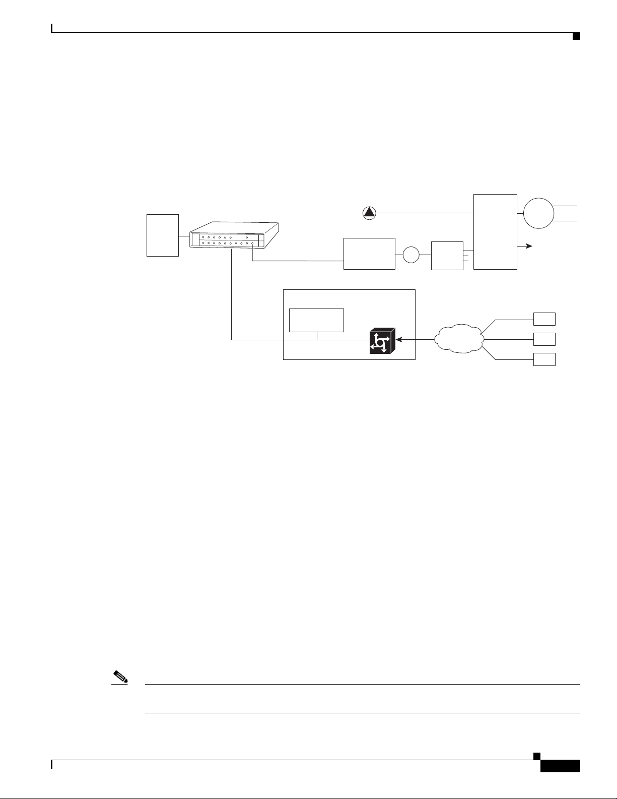
Chapter 4 Connecting the Cisco uBR7225VXR Router to the Cable Headend
One-Way Data Headend Architecture
Figure 4-2 shows a typical headend configuration configured for one-way (downstream) data in a telco
return cable system.
Figure 4-2 Typical Cable Headend Configuration for One-Way (Telco Return) Data
headend feed
0 to 20 dB
attenuator
(as required)
DHCP
TFTP
TOD
servers
Cisco
uBR7225VXR
Downstream
Main
8-way
tap
One-Way Data Headend Architecture
Laser
transmitter
Broadcast
Narrowcast
3-way
splitter
+17 dBmV
video carrier
(typical)
+7 dBmV
data carrier
(typical)
Optical
splitter
Node 1
Node 2
Downstream
forward
test point
Upstream
RF and Digital Data Overview
This section describes the interaction of digital and analog RF data as both signals are carried on the
hybrid fiber-coaxial (HFC) network.
Two-way digital data signals are more susceptible than one-way signals to stresses in the condition of
the HFC network. Degradation in video signal quality might not be noticed, but when two-way digital
signals share the network with video signals, digital signals might be hampered by the following types
of network impairments:
• Impulse and electrical noise—Impulse and electrical noise, usually forms of ingress, can enter the
network from sources within a home, such as hair dryers, light switches, and thermostats; or from
high-voltage lines that run near CATV cabling in the network. Areas of signal ingress may be located
and repaired by implementing a comprehensive signal leakage maintenance program.
• Amplifier thermal noise—Amplifiers add noise to the HFC network that usually goes unnoticed in
video signals, assuming a properly designed and operated network. Improperly configured
amplifiers will degrade digital data signals. The larger the network, the higher the probability of
amplifier thermal noise affecting the signals.
• Ingress noise—Ingress noise includes electrical sources (see “Impulse and electrical noise” above);
amateur radio transmissions; citizens band radios; or high-power shortwave broadcast signals,
which can interfere with frequencies anywhere between 3 and 65 MHz. These often are picked up
by cabling and equipment in the network.
IP network access
RADIUS dial
security server
Cisco network
access server
Telco return
cable modems
PSTN
271672
OL-17309-02
Note Some HFC upstream equipment passes interfering signals below 5 MHz, which may overload the reverse
path.
Cisco uBR7225VXR Universal Broadband Router Hardware Installation Guide
4-3
Page 74

Chapter 4 Connecting the Cisco uBR7225VXR Router to the Cable Headend
Connecting and Configuring the Downstream
• Noise funneling—The upstream data path to the headend is susceptible to picking up noise and
interference from anywhere in the network, and all upstream noise ultimately ends up at the
headend. This effect is known as noise funneling because of the cumulative nature of the noise from
one or more locations in the network that becomes concentrated at the headend. As a network
serviced by a single upstream receiver increases in size, the probability of noise funneling also
increases.
• Variable transmit levels—Signal loss over coaxial cable is affected by temperature. This can cause
variations of 6 to 10 dB per year.
• Clipping—The lasers in fiber-optic transmitters can stop transmitting light (clipping) when input
levels are excessive. Excessive input levels may cause bit errors and reduced data throughput in both
the upstream and downstream transmissions. If a laser is overdriven as briefly as a fraction of a
second, clipping can occur.
Connecting and Configuring the Downstream
After you install the Cisco uBR7225VXR universal broadband router in your headend site, you must
connect the Cisco uBR7225VXR router to the HFC network and configure the network. The following
sections describe how to connect to and configure the downstream.
Installing and Configuring the Upconverter
The Cisco uBR-MC16U/E-16U and Cisco uBR-MC28U/E-28U cable interface line cards have an
onboard integrated upconverter that generates an RF signal suitable for connection to a combiner and
transmission on the coaxial cable network, without the need for any external upconverters.
Note For more information, refer to the Cisco uBR7200 Series Cable Interface Line Card Hardware
Installation Guide at the following URL:
http://www.cisco.com/en/US/docs/interfaces_modules/cable/line_cards/installation/guide/mcxxfru.htm
l
Measuring the Downstream RF Signal
The configuration of the downstream digitally modulated carrier at the headend is critical to the
performance of the Cisco uBR7225VXR universal broadband router and cable modems. The following
guidelines are provided to assist you in configuring the RF signal to the necessary specifications. There
are two options you can use to measure the RF signal with a spectrum analyzer. These options are
described in the following sections:
• Measuring the Downstream RF Signal Using the Channel Power Option on a Spectrum Analyzer,
page 4-5
• Measuring the Downstream RF Signal Using CATV Mode on a Spectrum Analyzer, page 4-11
(equipped with digital channel power mode)
4-4
Cisco uBR7225VXR Universal Broadband Router Hardware Installation Guide
OL-17309-02
Page 75

Chapter 4 Connecting the Cisco uBR7225VXR Router to the Cable Headend
These two sections describe the procedures necessary to use a spectrum analyzer. You may also use a
signal level meter that has the ability to measure the average power level of digitally modulated carriers,
as well as a QAM analyzer. Some instruments to perform these measurements include:
• Acterna SDA-5000 w/Option 4 (http://www.acterna.com)
• Agilent 8591C, N1776A, 2010 or 3010 (http://www.tm.agilent.com)
• Sunrise Telecom AT-2000RQ, CM1000 or CR1200R (http://www.sunrisetelecom.com)
• Telsey DMA-120, DMA-121 or DMA122 (http://www.telsey.it)
• Trilithic 860DSP w/Option QA1 (http://www.trilithic.com)
If you complete these measurements using one of the previously mentioned options, your downstream
signal can be verified as correctly configured and it can assist you with troubleshooting your network
later on.
If you want to measure the downstream RF signal using the spectrum analyzer channel power option,
proceed to the following section, “Measuring the Downstream RF Signal Using the Channel Power
Option on a Spectrum Analyzer.” If you want to measure the downstream RF signal using CATV mode,
proceed to the “Measuring the Downstream RF Signal Using CATV Mode on a Spectrum Analyzer”
section on page 4-11.
Measuring the Downstream RF Signal
Measuring the Downstream RF Signal Using the Channel Power Option on a Spectrum Analyzer
The following sections describe how to measure the downstream RF signal using the channel power
option on a spectrum analyzer:
• Measuring the Downstream IF Signal at the Cisco uBR7225VXR Router, page 4-5
• Measuring the Downstream RF Signal at the Upconverter Output, page 4-7
Measuring the Downstream IF Signal at the Cisco uBR7225VXR Router
Note Refer to the user guide that accompanied your spectrum analyzer to determine the exact steps required
to use your analyzer to perform these measurements.
Step 1 Connect a spectrum analyzer to the downstream connector on a Cisco cable interface line card installed
in a Cisco uBR7225VXR router.
Step 2 Turn the power switch on the spectrum analyzer to the ON position.
Step 3 Set the spectrum analyzer to view the downstream intermediate frequency (IF) signal with a center
frequency of 44 MHz for a North American headend or 36.125 MHz for a European headend.
Step 4 Set the span to 10 MHz. Your analyzer should display a signal similar to the one shown in Figure 4-3.
OL-17309-02
Cisco uBR7225VXR Universal Broadband Router Hardware Installation Guide
4-5
Page 76

Measuring the Downstream RF Signal
Figure 4-3 Viewing the Downstream IF Signal on a Spectrum Analyzer
Chapter 4 Connecting the Cisco uBR7225VXR Router to the Cable Headend
Step 5
Measure the IF signal using the channel power option on your spectrum analyzer. Set your channel
spacing and your channel bandwidth to 6 MHz. Your analyzer should display a signal similar to the one
shown in Figure 4-4.
Figure 4-4 Measuring the IF Channel Power
Note The IF channel power in Figure 4-4 is +34.23 dBmV, as displayed on the spectrum analyzer.
4-6
Step 6 Select the video averaging feature. Your spectrum analyzer should display a signal similar to the one
shown in Figure 4-5.
Cisco uBR7225VXR Universal Broadband Router Hardware Installation Guide
OL-17309-02
Page 77
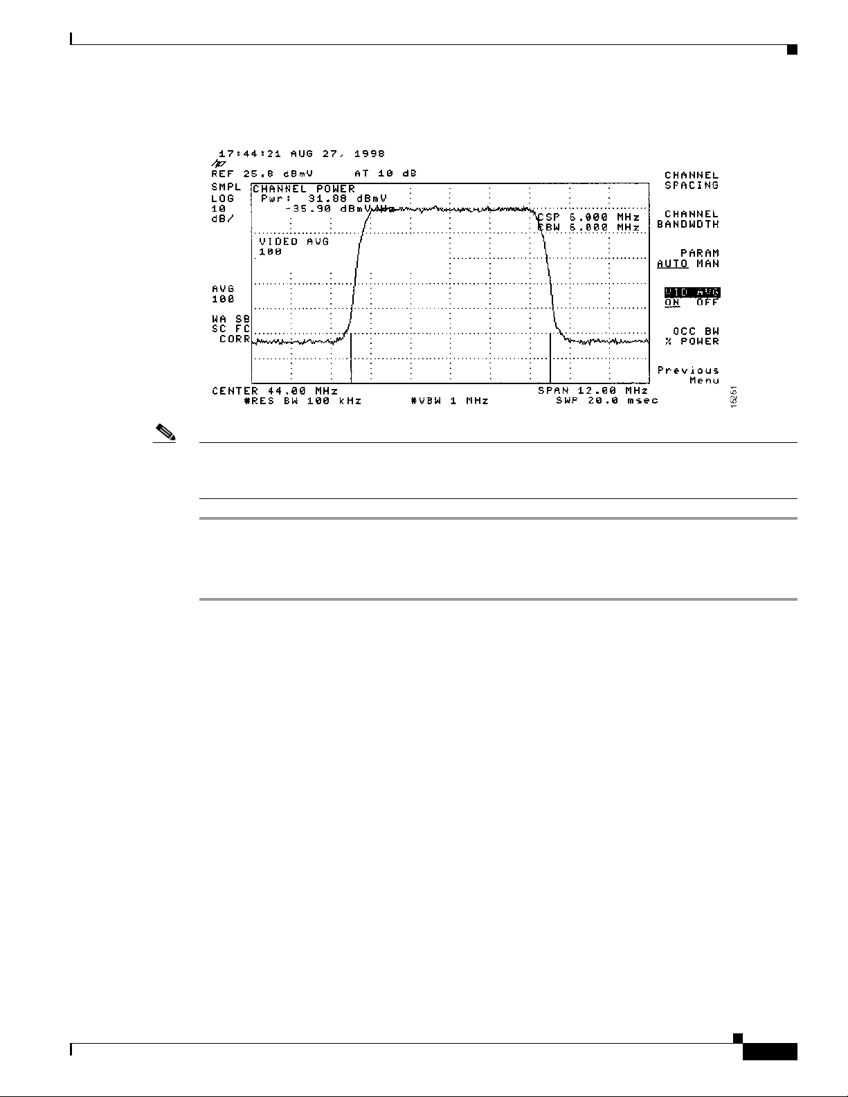
Chapter 4 Connecting the Cisco uBR7225VXR Router to the Cable Headend
Figure 4-5 Measuring the IF Channel Power Using Video Averaging
Measuring the Downstream RF Signal
Note The approximate in-channel peak-to-valley flatness may be verified using the spectrum analyzer’s video
averaging feature. Be aware, however, that amplitude values registered while in the video averaging
mode are typically around 2.5 dB below the actual channel power.
Measuring the Downstream RF Signal at the Upconverter Output
Step 1 Disconnect the spectrum analyzer from the cable interface line card downstream connector.
Step 2 Connect the downstream output of the cable interface line card to the upconvertor input connector.
Step 3 Connect the spectrum analyzer to the RF output of the upconverter. If your spectrum analyzer input is
overloaded, you might see artifacts that are internally generated by the spectrum analyzer. The artifacts
are circled on the analyzer trace shown in Figure 4-6. Add attenuation as necessary to correct the
overload condition.
OL-17309-02
Cisco uBR7225VXR Universal Broadband Router Hardware Installation Guide
4-7
Page 78

Measuring the Downstream RF Signal
Figure 4-6 Overloaded Spectrum Analyzer Input
Chapter 4 Connecting the Cisco uBR7225VXR Router to the Cable Headend
Step 4
Set the input of the upconverter to a digital QAM signal and the output level to the manufacturer’s
recommended settings. Typical output amplitudes range from +50 to +58 dBmV, although DOCSIS
specifies +61 dBmV.
Step 5 Set the spectrum analyzer to view the RF signal at the center frequency you selected for your headend.
In this example, the RF center frequency is 699 MHz. Set your span to 20 MHz. Finally, set your channel
spacing and your channel bandwidth to 6 MHz.
If the RF signal is causing an overload condition on the spectrum analyzer input, your analyzer might
display a signal similar to the one shown in Figure 4-7. The sloping of the lines at the sides of the signal
indicates a false reading.
Figure 4-7 Measuring the RF Signal at the Upconverter Output—Overload Condition
4-8
Step 6
If you add attenuation to the input to the spectrum analyzer you can correct the overload condition as
shown in Figure 4-8.
Cisco uBR7225VXR Universal Broadband Router Hardware Installation Guide
OL-17309-02
Page 79

Chapter 4 Connecting the Cisco uBR7225VXR Router to the Cable Headend
Figure 4-8 Measuring the RF Signal at the Upconverter Output—Overload Condition Corrected
with Attenuation
Measuring the Downstream RF Signal
Step 7
Change the spectrum analyzer settings to view the digital channel power. This setting enables you to see
if there is too much power on the upconverter output. In Figure 4-9, the upconverter output is reading
+64.31 dBmV, which is beyond the DOCSIS-specified range of +50 to +61 dBmV.
Tip A spectrum analyzer might become overloaded and produce false readings (such as internally generated
spurs) when measuring a signal at this amplitude.
Figure 4-9 Measuring the RF Signal at the Upconverter Output—Upconverter Output Level Too
High
OL-17309-02
Step 8
Adjust the power on the upconverter output to ensure that it is between +50 and +61 dBmV. In
Figure 4-10, the upconverter output is reading +57.06 dBmV, which is within the correct range.
Cisco uBR7225VXR Universal Broadband Router Hardware Installation Guide
4-9
Page 80

Measuring the Downstream RF Signal
Figure 4-10 Measuring the RF Signal at the Upconverter Output—Output Adjusted to Correct
Chapter 4 Connecting the Cisco uBR7225VXR Router to the Cable Headend
Range
Step 9
Select the video averaging feature on the spectrum analyzer. The signal becomes smoother and
frequency response problems might become visible. Your analyzer now displays an RF signal similar to
the one shown in Figure 4-11.
Figure 4-11 Measuring the RF Signal at the Upconverter Output Using Video Averaging
4-10
Note The approximate in-channel peak-to-valley flatness may be verified using the spectrum analyzer’s video
averaging feature. Be aware, however, that amplitude values registered while in the video averaging
mode are typically around 2.5 dB below the actual channel power.
Cisco uBR7225VXR Universal Broadband Router Hardware Installation Guide
OL-17309-02
Page 81

Chapter 4 Connecting the Cisco uBR7225VXR Router to the Cable Headend
Measuring the Downstream RF Signal
Step 10 Verify that your headend RF measurements meet the recommended DOCSIS parameters listed in the
tables in Appendix B, “RF Specifications.” Record your headend settings and measurements in your
headend site log (Appendix G, “Site Log”). This will assist in troubleshooting the
Cisco uBR7225VXR router installation later in the process.
This completes the procedure to measure the downstream RF signal using the channel power option.
Proceed to the “Measuring the RF Signal at the Forward Test Point on a Laser Transmitter” section on
page 4-37.
Measuring the Downstream RF Signal Using CATV Mode on a Spectrum Analyzer
The following two sections describe the methods you may use to measure the downstream RF signal
using CATV mode (digital channel power option) on a spectrum analyzer:
• Measuring the Downstream IF Signal at the Cisco uBR7225VXR Router Using CATV Mode,
page 4-11
• Measuring the Downstream RF Signal at the Upconverter Output Using CATV Mode, page 4-14
Note We recommend using as recent a model of spectrum analyzer as possible to perform the two analyses
described here. You can use spectrum analyzers, such as the Agilent 8591C (http://www.tm.agilent.com)
or the Tektronix 2715 (http://www.tek.com) to help you perform the tasks outlined in this section.
Measuring the Downstream IF Signal at the Cisco uBR7225VXR Router Using CATV Mode
Note Refer to the user guide that accompanied your spectrum analyzer to determine the exact steps required
to use your analyzer to perform these measurements.
Step 1 Connect a spectrum analyzer to the downstream connector on a Cisco cable interface card installed in a
Cisco uBR7225VXR router.
Step 2 Turn the power switch on the spectrum analyzer to the on position.
Step 3 Set the spectrum analyzer to CATV mode (CATV analyzer option) and select the channel measurement
option to view the downstream intermediate frequency (IF) signal. Your analyzer should display a signal
similar to the one shown in Figure 4-12.
Note Figure 4-12 shows the first of three screens that will be displayed by an Agilent 8591C when you use the
analyzer in this mode. Figure 4-13 is the last of the three screens displayed.
OL-17309-02
Cisco uBR7225VXR Universal Broadband Router Hardware Installation Guide
4-11
Page 82
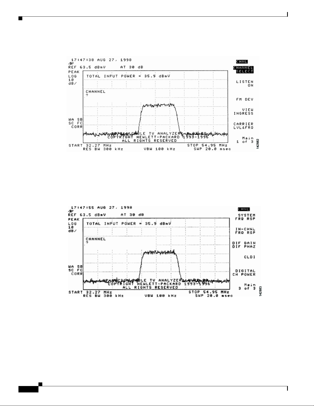
Measuring the Downstream RF Signal
Figure 4-12 Viewing the Downstream IF Signal on a Spectrum Analyzer in CATV Mode—Initial
Chapter 4 Connecting the Cisco uBR7225VXR Router to the Cable Headend
Screen
Step 4 Advance to the last of the three screens in this display. Your analyzer should display a signal similar to
the one shown in Figure 4-13.
Figure 4-13 Viewing the IF Signal on a Spectrum Analyzer in CATV Mode—Preliminary Digital
Channel Power Screen
Step 5
Enter a digital channel to measure and select digital channel power. Your spectrum analyzer will display
a signal similar to the one shown in Figure 4-14.
4-12
Cisco uBR7225VXR Universal Broadband Router Hardware Installation Guide
OL-17309-02
Page 83

Chapter 4 Connecting the Cisco uBR7225VXR Router to the Cable Headend
Figure 4-14 Measuring the IF Signal on a Spectrum Analyzer in CATV Mode—Digital Channel
Power Screen
Measuring the Downstream RF Signal
Step 6
Using the spectrum analyzer’s reference level control, adjust the amplitude of the displayed signal until
the shape of the signal is clearly distinguishable as a digitally modulated carrier, as shown in
Figure 4-15.
Figure 4-15 Measuring the IF Signal on a Spectrum Analyzer in CATV Mode—Adjusted Digital
Channel Power Screen
OL-17309-02
Note The IF channel power in Figure 4-15 is +33 dBmV, as displayed on the spectrum analyzer.
Step 7 Select the video averaging feature. Your spectrum analyzer should display a signal similar to the one
shown in Figure 4-16.
Cisco uBR7225VXR Universal Broadband Router Hardware Installation Guide
4-13
Page 84
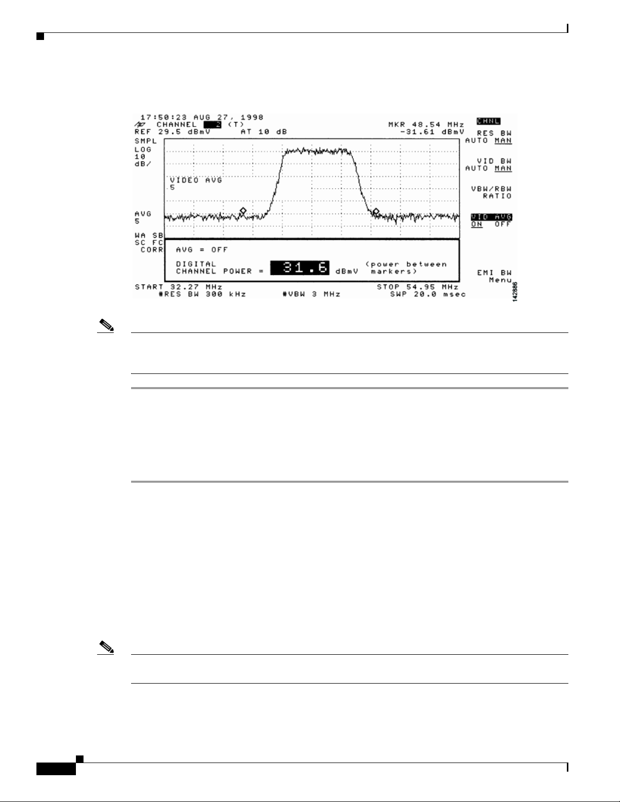
Measuring the Downstream RF Signal
Figure 4-16 Measuring the IF Signal on a Spectrum Analyzer in CATV Mode—Digital Channel
Chapter 4 Connecting the Cisco uBR7225VXR Router to the Cable Headend
Power Screen (Using Video Averaging)
Note The approximate in-channel peak-to-valley flatness can be verified using the spectrum analyzer’s video
averaging feature. Be aware, however, that amplitude values registered while in the video averaging
mode are typically around 2.5 dB below the actual channel power.
Proceed to the next section, “Measuring the Downstream RF Signal at the Upconverter Output Using
CATV Mode.”
Measuring the Downstream RF Signal at the Upconverter Output Using CATV Mode
Step 1 Disconnect the spectrum analyzer from the cable interface card downstream connector.
Step 2 Connect the downstream output of the cable interface card to the upconverter input connector.
Step 3 Connect the spectrum analyzer to the RF output of the upconverter.
Step 4 Set the upconverter output level to the manufacturer’s recommended settings. Typical output amplitudes
range from +50 to +58 dBmV, although DOCSIS specifies levels as high as +61 dBmV.
Step 5 Set the spectrum analyzer to view the RF signal at the center frequency you selected for your headend.
In this example, the RF center frequency is 705 MHz.
Step 6 Set the spectrum analyzer to CATV mode (CATV analyzer option) and select the channel measurement
option to view the downstream RF signal. Your spectrum analyzer should display a signal similar to the
one shown in Figure 4-12.
4-14
Note Figure 4-17 shows the first of three screens that will be displayed by an Agilent 8591C when you use the
analyzer in this mode. Figure 4-18 is the last of the three screens displayed.
Cisco uBR7225VXR Universal Broadband Router Hardware Installation Guide
OL-17309-02
Page 85
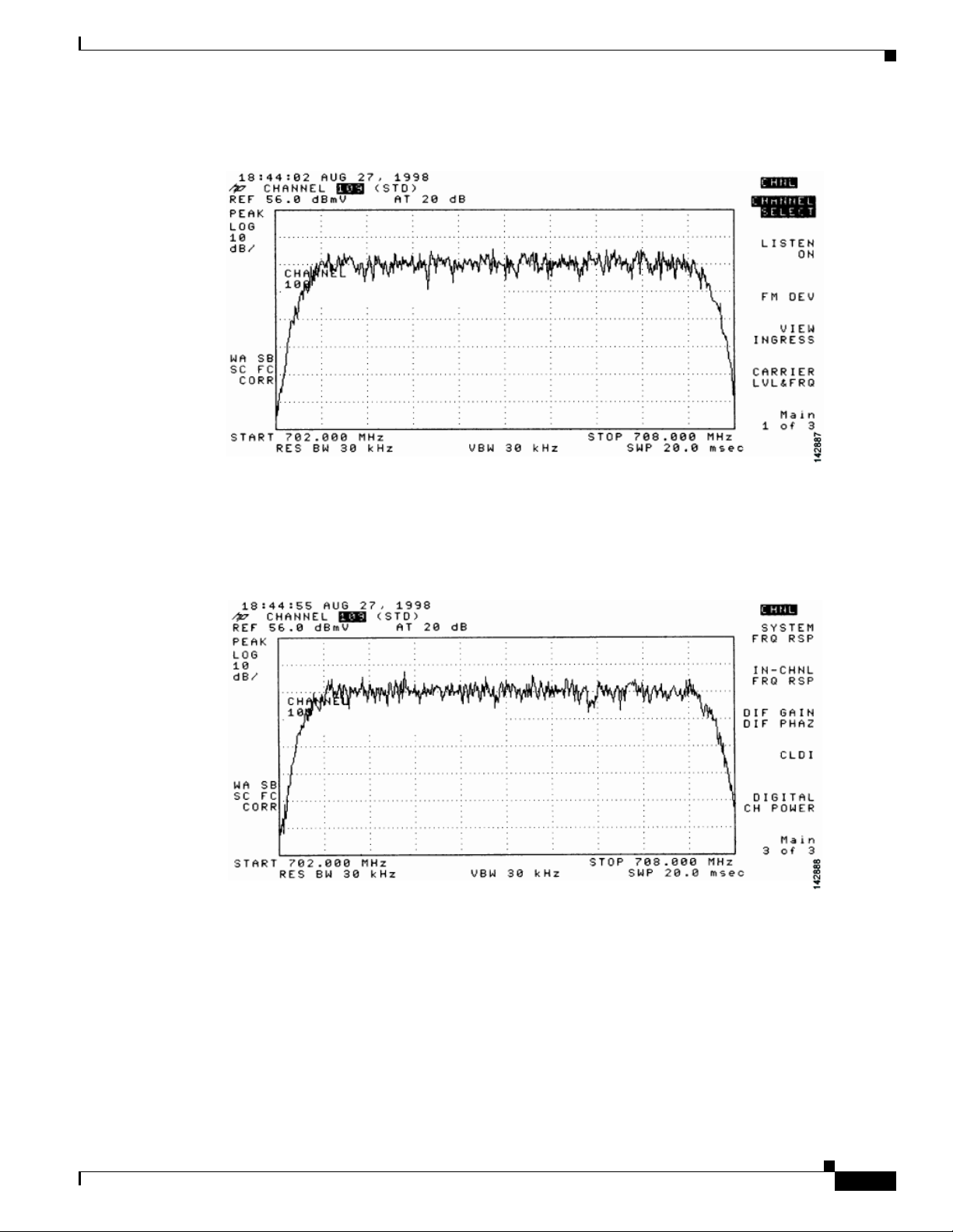
Chapter 4 Connecting the Cisco uBR7225VXR Router to the Cable Headend
Figure 4-17 Viewing the Downstream RF Signal on a Spectrum Analyzer in CATV Mode—Initial
Screen
Measuring the Downstream RF Signal
Step 7
Step 8
Advance to the last of the three screens in this display. Your analyzer should display a signal similar to
the one shown in Figure 4-18.
Figure 4-18 Viewing the RF Signal on a Spectrum Analyzer in CATV Mode—Preliminary Digital
Channel Power Screen
Enter a digital channel to measure and select digital channel power. Your spectrum analyzer will display
a signal similar to the one shown in Figure 4-19.
OL-17309-02
Cisco uBR7225VXR Universal Broadband Router Hardware Installation Guide
4-15
Page 86

Measuring the Downstream RF Signal
Figure 4-19 Measuring the RF Signal at the Upconverter Output in CATV Mode—Digital Channel
Chapter 4 Connecting the Cisco uBR7225VXR Router to the Cable Headend
Power Screen
Step 9
Step 10
Using the spectrum analyzer’s reference level control, adjust the amplitude of the displayed signal until
the signal peak is within the top graticule of the analyzer’s display grid, as shown in Figure 4-20.
Figure 4-20 Measuring the RF Signal at the Upconverter Output in CATV Mode—Adjusted Digital
Channel Power Screen
Select the video averaging feature. Your spectrum analyzer should display a signal similar to the one
shown in Figure 4-21.
4-16
Cisco uBR7225VXR Universal Broadband Router Hardware Installation Guide
OL-17309-02
Page 87
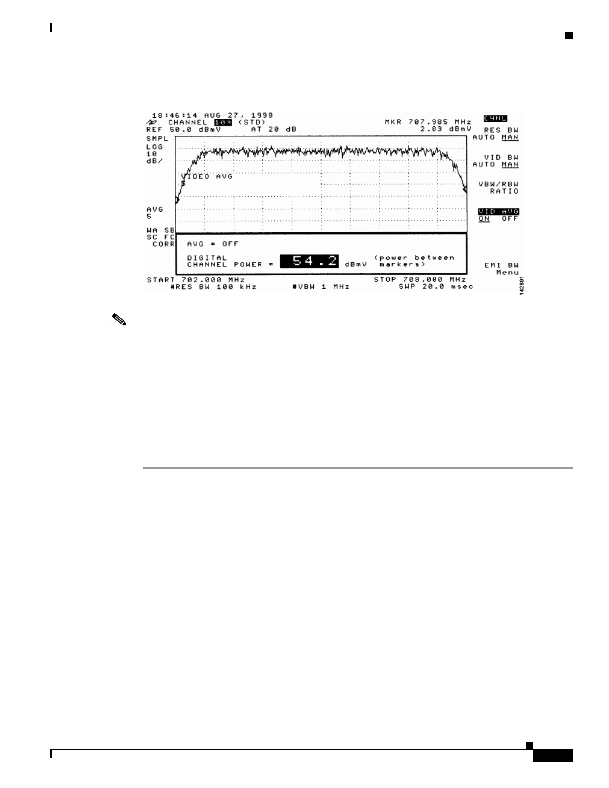
Chapter 4 Connecting the Cisco uBR7225VXR Router to the Cable Headend
Figure 4-21 Measuring the RF Signal at the Upconverter Output in CATV Mode—Digital Channel
Power Screen Using Video Averaging
Measuring the Downstream RF Signal
Note The approximate in-channel peak-to-valley flatness can be verified using the spectrum analyzer’s video
averaging feature. Be aware, however, that amplitude values registered while in the video averaging
mode are typically around 2.5 dB below the actual channel power.
Step 11 Verify that your headend RF measurements meet the recommended DOCSIS parameters listed in the
tables in Appendix B, “RF Specifications.”
Step 12 Record your headend settings and measurements in Appendix G, “Site Log.” as you verify them. This
will assist in troubleshooting the Cisco uBR7225VXR router installation later in the process.
Step 13 After you have analyzed and adjusted the RF signal according to the steps outlined on the preceding
pages, proceed to the “Connecting and Configuring the Upstream” section on page 4-18.
OL-17309-02
Cisco uBR7225VXR Universal Broadband Router Hardware Installation Guide
4-17
Page 88

Chapter 4 Connecting the Cisco uBR7225VXR Router to the Cable Headend
Connecting and Configuring the Upstream
Connecting and Configuring the Upstream
The following sections describe how to connect and configure the upstream for digital data.
Connecting the Upstream to the Optical Receiver
To connect the upstream to the optical receiver, use a 2-way splitter as a combiner to leave the DOCSIS
cable modem connected at the headend, and connect the upstream headend cable to the optical receiver.
(See Figure 4-22.)
The default upstream input level to the Cisco uBR7225VXR cable interface line card is 0 dBmV. You
may adjust the upstream input level to other values using the Cisco IOS software running on your router.
The Cisco uBR7225VXR router uses automatic power control when transmitting to remote
cable modems. Accurately setting the power level helps to ensure reliable cable modem operation.
Table 4-1 provides upstream input power ranges for the various cable interface line cards available for
the Cisco uBR7225VXR router, depending on the channel bandwidth you are using.
Table 4-1 Upstream Input Power Ranges According to Cable Interface Line Card Type
Channel Bandwidth Cisco MC11 FPGA Cisco MC16E and MC16S DOCSIS Specification
200 KHz N/A –10 to +25 dBmV –16 to +14 dBmV
400 KHz N/A –10 to +25 dBmV –13 to +17 dBmV
800 KHz N/A –10 to +25 dBmV –10 to +20 dBmV
1.6 MHz –10 to +10 dBmV –10 to +25 dBmV –7 to +23 dBmV
3.2 MHz N/A –10 to +25 dBmV –4 to +26 dBmV
Note If you have a Cisco uBRMC16x cable interface line card (six upstream ports and one downstream port)
installed in your Cisco uBR7225VXR router, the 2-way splitter described above would be replaced by
six 2-way splitters (one splitter per upstream port). This would enable you to connect to all of the
available upstream ports on the Cisco uBRMC16x.
4-18
Cisco uBR7225VXR Universal Broadband Router Hardware Installation Guide
OL-17309-02
Page 89

Chapter 4 Connecting the Cisco uBR7225VXR Router to the Cable Headend
14045
Spectrum analyzer
Optical
receiver
Fiber node
0.5 milliwatt
Fiber node
1.0 milliwatt
Spectrum analyzer
Optical
receiver
1dB attenuator
+11 dBmV
X-level test point = +10 dBmV
(in this example)
30 km
10 km
+17 dBmV
Insert +17 dBmV signal
X
Measure +10 dBmV at this point
Insert +17 dBmV signal
Figure 4-22 Connecting and Configuring the Upstream
Cisco
uBR7225VXR
Upstream
2-way
splitter
(combiner)
10 dB
attenuator
Diplex filter
40 dB
attenuator
Cable
modem
X-level test point signal level
must be the same for all
optical receivers (+/- 0.5 dB),
See Fig. 4-36 and Fig 4-37
LH
C
To downstream forward
test point on laser transmitter
Connecting and Configuring the Upstream
Optional attenuator
X
to adjust X-level point
measurement
Optical
receiver
271676
Testing the Upstream Configuration
To test the upstream configuration, insert a test signal of known amplitude (+17 dBmV is shown in this
example) into the fiber node and measure the amplitude output level at the output of the headend’s
optical receiver. This measurement depends on return laser performance and optical distance. This
procedure is known as establishing the “X-level” test point. (See Figure 4-23.)
Figure 4-23 The “X-level” Test Point
OL-17309-02
Cisco uBR7225VXR Universal Broadband Router Hardware Installation Guide
4-19
Page 90

Chapter 4 Connecting the Cisco uBR7225VXR Router to the Cable Headend
Cisco
uBR7225VXR
Downstream
Upstream
0 dBmV
3 dB
attenuator
3 dB
attenuator
3 dB
attenuator
40 dB
attenuator
3 dB
attenuator
8 dB
attenuator
21 dB
attenuator
Cable
modems
+48 dBmV
+31 dBmV
+42 dBmV
+50 dBmV
+46 dBmV
+49 dBmV
+58 dBmV
4-way
splitter
X
X
X
+10 dBmV
+10 dBmV
+10 dBmV
To downstream
forward test point
on laser transmitter
+13 dBmV
+18 dBmV
+31 dBmV
Reverse optical
transmitter
Optical
receiver
Fiber-optic
cable
Distribution
network
+17 dBmV
Reverse optical
transmitter
Optical
receiver
Fiber-optic
cable
Distribution
network
+17 dBmV
Reverse optical
transmitter
Optical
receiver
Fiber-optic
cable
Distribution
network
+17 dBmV
Modem transmit levels
Modem transmit levels
Modem transmit levels
Cable
modem
LH
C
Diplex filter
Connecting and Configuring the Upstream
This “X-level” test point measurement will be different for every fiber node in the HFC network until
you adjust the attenuation on the upstream. You must adjust the attenuation so that this measurement is
the same on every fiber node. If you change a receiver or a transmitter at the fiber node, or if you unplug
a connector and plug it back in, you must recheck this amplitude measurement. Figure 4-24 shows how
three distribution network “X-level” test points connected to the same upstream port are all calibrated to
+10 dBmV using different attenuators.
Figure 4-24 Calibrating Multiple “X-level” Test Points Connected to One Upstream Port
4-20
Figure 4-25 shows how three distribution network “X-level” test points connected to the three different
Cisco uBR7225VXR Universal Broadband Router Hardware Installation Guide
upstream ports are all calibrated to +10 dBmV using different attenuators.
OL-17309-02
Page 91
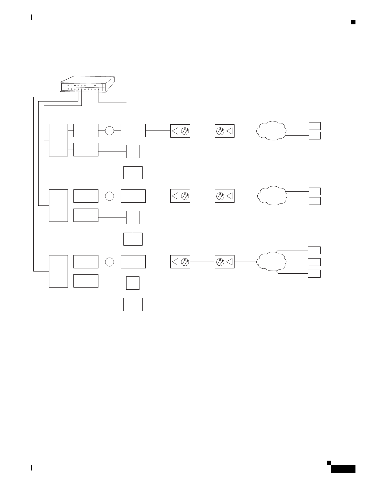
Chapter 4 Connecting the Cisco uBR7225VXR Router to the Cable Headend
Connecting and Configuring the Upstream
Figure 4-25 Calibrating Multiple “X-level” Test Points Connected to Multiple Upstream Ports
Cisco
uBR7225VXR
Upstream
0 dBmV
2-way
splitter
2-way
splitter
2-way
splitter
6 dB
attenuator
40 dB
attenuator
6 dB
attenuator
40 dB
attenuator
6 dB
attenuator
40 dB
attenuator
Downstream
+10 dBmV
X
+10 dBmV
X
+10 dBmV
X
3 dB
attenuator
Diplex filter
LH
C
Cable
modem
3 dB
attenuator
Diplex filter
LH
C
Cable
modem
21 dB
attenuator
Diplex filter
LH
C
Cable
modem
+13 dBmV
Downstream
(0 to +5 dBmV)
+18 dBmV
Downstream
(0 to +5 dBmV)
+31 dBmV
Downstream
(0 to +5 dBmV)
Optical
receiver
Optical
receiver
Optical
receiver
Fiber-optic
cable
Fiber-optic
cable
Fiber-optic
cable
Reverse optical
transmitter
Reverse optical
transmitter
Reverse optical
transmitter
+17 dBmV
+17 dBmV
+17 dBmV
Distribution
network
Distribution
network
Distribution
network
+31 dBmV
+48 dBmV
Modem
transmit
levels
+58 dBmV
+42 dBmV
Modem
transmit
levels
+50 dBmV
+42 dBmV
+49 dBmV
Modem
transmit
levels
Cable
modems
271678
OL-17309-02
Cisco uBR7225VXR Universal Broadband Router Hardware Installation Guide
4-21
Page 92

Chapter 4 Connecting the Cisco uBR7225VXR Router to the Cable Headend
Measuring the Upstream RF Signal
Measuring the Upstream RF Signal
You can use a spectrum analyzer to measure the upstream signal from one or more remote cable modems
in a two-way data cable network. Performing this procedure can help alert you to potential problems in
your cable network’s upstream configuration before a problem occurs. This helps to avoid trying to solve
a problem after a remote cable modem has experienced a failure in service. This procedure is referred to
as the “zero-span” method.
Measuring the Upstream RF Signal Using a Spectrum Analyzer
This procedure is designed to help you accurately measure an upstream RF signal where no adjacent
channels are in use. To measure an upstream RF signal with active adjacent channels, refer to the “Using
the Zero-Span Method with Adjacent Upstream Channels” section on page 4-28.
Note Refer to the user guide that accompanied your spectrum analyzer to determine the exact steps required
to use your analyzer to perform these measurements.
Step 1 Connect the spectrum analyzer to the upstream signal from your cable network.
Step 2 Turn the power switch on the spectrum analyzer to the on position.
Step 3 Set the spectrum analyzer to view the upstream RF signal with a center frequency matching the actual
upstream center frequency defined in your Cisco uBR7225VXR router configuration file.
Step 4 Set the spectrum analyzer’s span to 0 MHz.
Note You can view the configuration file for your Cisco uBR7225VXR router by using the
show controller cable slot/upstream/port command, available in Cisco IOS Release 11.3(6)NA or later
releases and Cisco IOS Release 12.0(5)T1 or later releases. For example, if you wanted to view the
center frequency of port 0 on a cable interface card in slot 3, you would enter the
show controller cable 3/0 command.
If you have assigned spectrum groups in your configuration file, use the show cable hop command to
display the current upstream center frequency for each cable interface.
Step 5 Set both the resolution bandwidth and the video bandwidth on the spectrum analyzer to 3 MHz and the
sweep rate to 20 microseconds. Provided there is a large amount of activity on your upstream channel,
the spectrum analyzer should display a signal similar to the one shown in Figure 4-26.
4-22
Cisco uBR7225VXR Universal Broadband Router Hardware Installation Guide
OL-17309-02
Page 93

Chapter 4 Connecting the Cisco uBR7225VXR Router to the Cable Headend
Figure 4-26 Measuring the Upstream RF Signal—Setting the Resolution and Video Channel
Bandwidth
Measuring the Upstream RF Signal
Tip The horizontal line passing through the center of the spectrum analyzer display in Figure 4-26 is the
trigger line.
Step 6 Set the sweep value to 80 microseconds. Your spectrum analyzer should display a signal similar to the
one shown in Figure 4-27.
Note Be sure that your particular spectrum analyzer is capable of supporting sweep times as short as 80
microseconds.
Figure 4-27 Measuring the Upstream RF Signal—Setting the Sweep Time Period
OL-17309-02
Step 7
Position the trigger line on the spectrum analyzer so that it is roughly in the middle (approximately
halfway between the highest and lowest portions) of the upstream RF signal.
Cisco uBR7225VXR Universal Broadband Router Hardware Installation Guide
4-23
Page 94

Measuring the Upstream RF Signal
Note Refer to the documentation that accompanied your particular spectrum analyzer for detailed instructions
on activating and positioning the trigger line.
A known workaround exists for the Agilent 8591C spectrum analyzer. After activating and positioning
the trigger line in video mode, you must press the “video” button on the spectrum analyzer once more to
enable proper functionality.
Step 8 Adjust the amplitude on your spectrum analyzer so that the uppermost portion of the upstream RF signal
is in the top graticule of the analyzer’s display grid and adjust the trigger line accordingly. Your spectrum
analyzer will then display an upstream RF signal similar to the one shown in Figure 4-28.
Note We do not recommend using the spectrum analyzer’s “max-hold” feature while analyzing upstream
signals in the frequency domain. “Max-hold” readings in the frequency domain can be inaccurate
because the analyzer focuses on the peak power of the strongest ranging modem rather than the power
levels of cable modems that are operating in a more ideal range.
Figure 4-28 Measuring the Upstream RF Signal—Accurately Measured Amplitude on Spectrum
Chapter 4 Connecting the Cisco uBR7225VXR Router to the Cable Headend
Analyzer
4-24
Step 9
Position a marker about 7/8 of the way into the preamble of the signal, as illustrated in Figure 4-28. (The
preamble is the regular pattern displayed at the front of the signal and the length of the preamble is a
function of the channel width/data rate, modulation format, and DOCSIS burst-profile configurations.)
The peak amplitude of the marker, which registers +31.07 dBmV in this case, will be within 1 dB of the
true burst power.
Note To verify this reading, you can also measure the power rating with an Agilent 89441A vector signal
analyzer (http://www.tm.agilent.com).
If the preamble of your upstream signal is displayed with a significantly lower amplitude than the rest
of the RF signal, refer to the “Using the Zero-Span Method with Adjacent Upstream Channels” section
on page 4-28 for instructions on how to overcome this phenomenon.
Cisco uBR7225VXR Universal Broadband Router Hardware Installation Guide
OL-17309-02
Page 95

Chapter 4 Connecting the Cisco uBR7225VXR Router to the Cable Headend
Step 10 Verify that your headend RF measurements meet the recommended DOCSIS parameters listed in the
tables in Appendix B, “RF Specifications.”
Step 11 Record your headend settings in Appendix G, “Site Log.” This will assist in troubleshooting the
Cisco uBR7225VXR universal broadband router installation later in the process.
Note Be sure not to narrow the focus of your analysis any further than approximately 3-MHz channel width.
Doing so can yield incorrect readings. For example, if you were to view an upstream RF signal with a
resolution bandwidth of only 300 kHz and a video channel bandwidth of only 100 kHz, your
measurements would register lower than the actual transmission levels.
Analyzing the Upstream RF Signal
When you have set up your spectrum analyzer to accurately read the upstream RF signal, you can verify
that a remote cable modem is operating as it should by pinging the modem via a console terminal.
Measuring the Upstream RF Signal
Step 1 Log in to your Cisco uBR7225VXR universal broadband router with a console terminal.
Step 2 Adjust the sweep time on your spectrum analyzer to 20 microseconds.
Step 3 Ping the remote cable interface card using first a 64-byte, then a 1500-byte ping packet request, and take
note of the upstream RF signal in each case. Several hundred or thousand ping packets might be required
for a usable pattern to emerge.
Figure 4-29 and Figure 4-30 provide two examples of an ideal upstream RF signal based on a simple 64-
or 1500-byte ping of a single remote cable interface. The more slender of the data spikes in the RF signal
(the first and third spikes in Figure 4-29) are bandwidth request packet transmissions, while the larger
spikes are the actual 64- or 1500-byte ping packet returns.
Figure 4-29 Analyzing the Upstream RF Signal—64-Byte Data Packets
OL-17309-02
Cisco uBR7225VXR Universal Broadband Router Hardware Installation Guide
4-25
Page 96
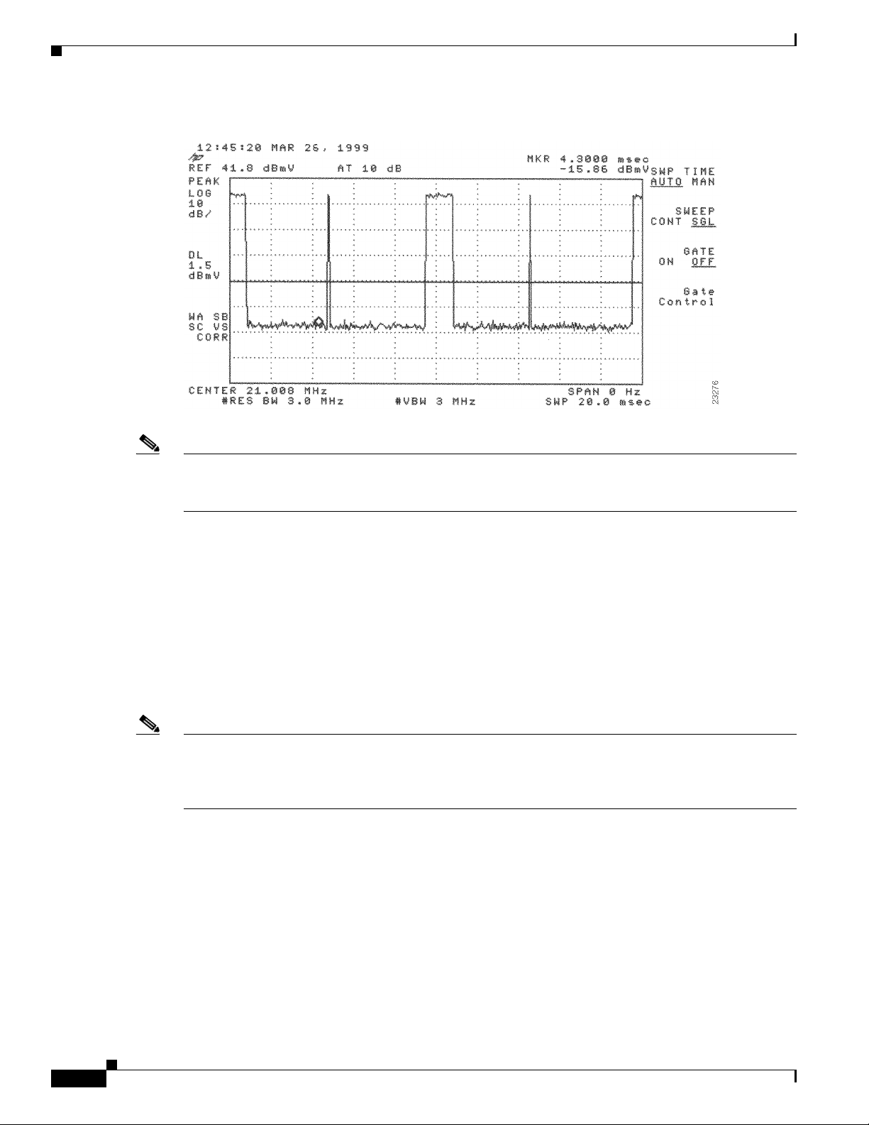
Measuring the Upstream RF Signal
Figure 4-30 Analyzing the Upstream RF Signal—1500-Byte Data Packets
Chapter 4 Connecting the Cisco uBR7225VXR Router to the Cable Headend
Note Both of the previous examples feature 16-QAM transmission with a channel width of 3.2 MHz, yielding
a 10-Mbit/sec data rate. In addition, these examples have an optimal upstream carrier-to-noise ratio of
approximately 50 dB.
Now it is time to view your upstream RF signal with multiple remote cable modems. Figure 4-31 and
Figure 4-32 both display upstream RF signals encompassing more than one remote cable modem. In
each case, there are two bandwidth requests followed by their respective ping packet returns, both at
slightly different amplitudes. This situation is most commonly caused by a difference in the receive
power from the two cable modems in question. In the example, the remote cable modem with the lesser
amplitude is “cable modem A” and the other is “cable modem B.”
In the following example, cable modem A and cable modem B have been artificially configured to yield
a larger than normal difference in amplitude between their respective upstream RF transmissions. Under
normal conditions, the maximum difference in amplitude between any cable modems will be about
1.5 dB. Differences greater than 1.5 dB indicate a possible cable plant or remote cable modem problem.
Note To further illustrate this point, you can log in to your Cisco uBR7225VXR router using a console
terminal and enter the show cable modem command to obtain a report of the receive power ratings for
each modem. In the example, the receive power ratings for remote cable modems A and B are –2 dBmV
and 0 dBmV, respectively.
The two bandwidth requests and ping packet returns on the upstream RF signal for cable modems A and
B are slightly different in Figure 4-31 and Figure 4-32. Differences in the distance between bandwidth
requests are primarily caused by the contention-based nature of multiple remote cable modems on the
same line. Differences in the distance between ping packet returns are primarily caused by factors such
as packet size and system loading.
4-26
Cisco uBR7225VXR Universal Broadband Router Hardware Installation Guide
OL-17309-02
Page 97
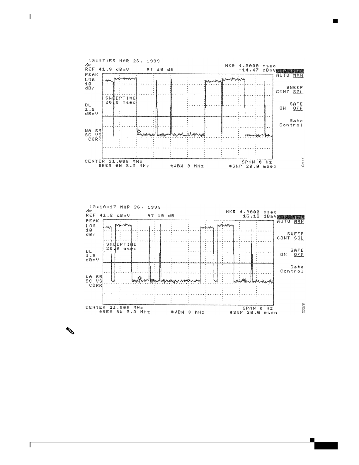
Chapter 4 Connecting the Cisco uBR7225VXR Router to the Cable Headend
Figure 4-31 Analyzing the Upstream RF Signal—Multiple Active Remote Cable Modems (A)
Measuring the Upstream RF Signal
Figure 4-32 Analyzing the Upstream RF Signal—Multiple Active Remote Cable Modems (B)
Note When viewing the upstream RF signal on your spectrum analyzer, two ping packet returns (for example,
from remote cable modems A and B) can be so close together that they appear to be one rather large
packet with a slight jump or decline in amplitude halfway through the measurement. This is an indication
that the upstream is 100 percent occupied during this time.
OL-17309-02
Figure 4-33 shows an upstrea m RF si gnal from a re mote cable modem in a “real-life” scenario including
outside plant noise. Notice the relatively tall spike at the very left edge of the ping packet return. This
spike is mainly additive noise associated with an upstream RF signal mired by excessive amounts of
severe outside plant noise (as in this example). In addition, notice that the carrier-to-impulse noise ratio
measurement between the two diamond-shaped markers is only about 12 dB. (A few other noise peaks
are even worse.)
Cisco uBR7225VXR Universal Broadband Router Hardware Installation Guide
4-27
Page 98

Measuring the Upstream RF Signal
The importance of this example is to bring to your attention the need for minimal outside plant noise.
Time-varying, fast noise can cause bit errors in packet transmissions, rendering your communication link
unreliable, if not unusable.
Figure 4-33 Analyzing the Upstream RF Signal—Outside Plant Noise Included
Chapter 4 Connecting the Cisco uBR7225VXR Router to the Cable Headend
Note This illustration depicts an upstream RF signal whose carrier-to-impulse noise ratio does not meet
DOCSIS 1.0 specifications. The data packet in Figure 4-33 was “dropped” due to severe noise
interference with a more narrow resolution bandwidth.
Using the Zero-Span Method with Adjacent Upstream Channels
When measuring upstream signals using the zero-span method, a very wide resolution and video
bandwidth give very accurate readings, but render your readings susceptible to energy in adjacent
channels. As the number of upstream services increases, so does the likelihood of interference from
adjacent channels. This section describes using the zero-span power measurement method, with a more
narrow resolution bandwidth.
Simply narrowing the resolution bandwidth will not yield accurate readings. See Tab le 4- 2.
Table 4-2 Sample Channel Width and Symbol Rate Combinations with Their Respective Minimum Resolution
Bandwidth Measurements
1/2
Center Frequency Channel Width Symbol Rate
Symbol Rate
20.000 200 kHz 160 80 20.080 and 19.020 MHz 10 kHz
30.000 400 kHz 320 160 30.160 and 29.840 MHz 30 kHz
40.000 800 kHz 640 320 40.320 and 39.680 MHz 100 kHz
25.000 1.6 MHz 1280 640 25.640 and 24.360 MHz 100 kHz
28.000 3.2 MHz 2560 1280 29.280 and 27.720 MHz 300 kHz
Center Frequency
+/–1/2 Symbol Rate
Minimum Resolution
Bandwidth
4-28
Cisco uBR7225VXR Universal Broadband Router Hardware Installation Guide
OL-17309-02
Page 99

Chapter 4 Connecting the Cisco uBR7225VXR Router to the Cable Headend
Step 1 Display a signal complete with preamble and upstream data transmission information similar to the
resulting signal from Step 3 through Step 10 under the “Measuring the Upstream RF Signal Using a
Spectrum Analyzer” section on page 4-22. Your spectrum analyzer should display a signal similar to the
one in Figure 4-34.
Figure 4-34 Preamble Amplitude Before Resolution and Video Bandwidth Reduction
Measuring the Upstream RF Signal
Note Figure 4-34 is a display from a standard spectrum analyzer. The following figures, Figure 4-35 through
Figure 4-38, are taken from a vector signal analyzer. If you do not have access to a vector signal analyzer,
or want to skip the following section describing its use when viewing your upstream signal, proceed to
Step 3.
Step 2 (Optional) View your upstream signal using a vector signal analyzer such as the Agilent 89441A.
The advantage of displaying these signals with the vector signal analyzer is that you can view them over
the time domain for a specified time interval. In addition, the vector signal analyzer enables you to
measure the digital channel power of a very short duration data transmission, like the preamble of a
digital signal.
a. Set up your vector signal analyzer to view both the “frequency” domain and “time” domain of your
upstream signal. Your vector signal analyzer should display a pair of signals similar to those in
Figure 4-35.
OL-17309-02
Cisco uBR7225VXR Universal Broadband Router Hardware Installation Guide
4-29
Page 100

Measuring the Upstream RF Signal
Figure 4-35 Vector Signal Analyzer Plot of Upstream Data Burst
Chapter 4 Connecting the Cisco uBR7225VXR Router to the Cable Headend
The upper graph in Figure 4-35 represents the frequency domain and the lower graph represents the
time domain.
In the time domain, the channel power of the preamble of a digital upstream signal is not spread
across the entire channel. However, the channel power of the remainder of the digital transmission
is spread across the entire channel. Even though it may not seem so, the total channel power across
both the preamble and the subsequent data segment remains constant.
b. Narrow the view on your vector signal analyzer to display only the preamble of the digital data
signal in both the frequency domain and time domain.
The upper display in Figure 4-36 is a plot of only the preamble portion of the digital signal in
Figure 4-35. Notice how the amplitude of the signal experiences many “peaks” and “valleys.” When
you are measuring the preamble power using the zero-span method, be sure that you measure the
actual signal energy (a peak), rather than accidentally measuring the power level of a valley in the
preamble.
4-30
Cisco uBR7225VXR Universal Broadband Router Hardware Installation Guide
OL-17309-02
 Loading...