

Page 1

Cisco uBR7200 Series Universal Broadband
Router AC Power Supply Replacement
Instructions
Product Numbers: PWR-UBR7200-AC, PWR-UBR7200-AC=,
PWR-UBR7200/2-AC, CHAS-UBR7246VXR=, CHAS-UBR7246=,
CHAS-UBR7225VXR=, PWR-UBR7225VXR-AC
This document explains how to remove and replace the 550-watt (W) AC-input power supply in the
Cisco uBR7200 series universal broadband routers (which consist of the Cisco uBR7246VXR and the
Cisco uBR7246). It includes instructions for powering down the routers, removing an installed power
supply, and installing a new power supply. This document also includes steps for verifying the
initialization of the system after you power up a Cisco uBR7200 series router.
Note Use this document in conjunction with the , and Regulatory Compliance and Safety Information for the .
The following sections are included in this document:
• If You Need More Information, page 1
• AC-Input Power Supply Overview, page 2
• Installation Prerequisites, page 4
• Removing and Replacing an AC-Input Power Supply, page 8
• Obtaining Documentation and Submitting a Service Request, page 17
If You Need More Information
The Cisco IOS software running on your router contains extensive features and functionality. For
additional information on configuring and maintaining the Cisco uBR7200 series, the following
documentation resources are available:
Americas Headquarters:
Cisco Systems, Inc., 170 West Tasman Drive, San Jose, CA 95134-1706 USA
© 2008 Cisco Systems, Inc. All rights reserved.
Page 2

AC-Input Power Supply Overview
• For Cisco IOS software configuration information, refer to the modular configuration and modular
command reference publications in the Cisco IOS software configuration documentation set that
corresponds to the software release installed on your Cisco hardware.
Note You can access Cisco IOS software configuration documentation at Cisco.com.
• For hardware installation and maintenance information on the Cisco uBR7200 series, refer to the
• For international agency compliance, safety, and statutory information for wide-area network
(WAN) interfaces for the Cisco uBR7200 series, refer to the Regulatory Compliance and Safety
Information for the Cisco uBR7200 Series Universal Broadband Routers that is shipped with your
Cisco uBR7200 series universal broadband router
• To obtain general information about documentation, refer to the “Obtaining Documentation and
Submitting a Service Request” section on page 17.
AC-Input Power Supply Overview
The Cisco uBR7225VXR router is equipped with the 300W AC-input power supply and the maximum
AC-input power with single or dual power supply configuration is 300W.
The Cisco uBR7246 and Cisco uBR7246VXR routers are equipped with the 550W AC-input power
supplies and the maximum AC-input power with single or dual power supply configuration is 800W.
Note To ensure adequate airflow across the Cisco uBR7225VXR, Cisco uBR7246VXR, and Cisco uBR7246
universal broadband routers’ power supplies, a power supply or a power supply filler plate (with its
attached air dam) must be installed in each power supply bay.
Do not mix AC-input and DC-input power supplies in the same Cisco uBR7246VXR or Cisco uBR7246
chassis.
Cisco uBR7225VXR
The power supply contains a main power switch, the OK LED, and the AC-input power receptacle. The
grounding lug at the rear-bottom portion of the Cisco uBR7225VXR chassis provides a ground
connection for electrostatic discharge (ESD) equipment.
The Cisco uBR7225VXR supports an optional, second power supply for load sharing and power
redundancy. If you purchased a Cisco uBR7225VXR and you want to install a second power supply, you
must order the second power supply separately.
A handle on the AC-input power supply unit provides a grip point for removing and replacing the power
supply. (Figure 1 shows the faceplate of the Cisco uBR7225VXR AC-input power supply.)
A single captive installation screw secures the power supply to the chassis and seats the power supply in
the router midplane. The AC-input power supply has a receptacle for an AC-input power cable. A
modular power cable connects the AC-input power supply to the site AC power source.
Note The AC-input power supply has an electrical current rating of 4A for the Cisco uBR7225VXR.
Cisco uBR7200 Series Universal Broadband Router AC Power Supply Replacement Instructions
2
78-4848-06
Page 3
AC-Input Power Supply Overview
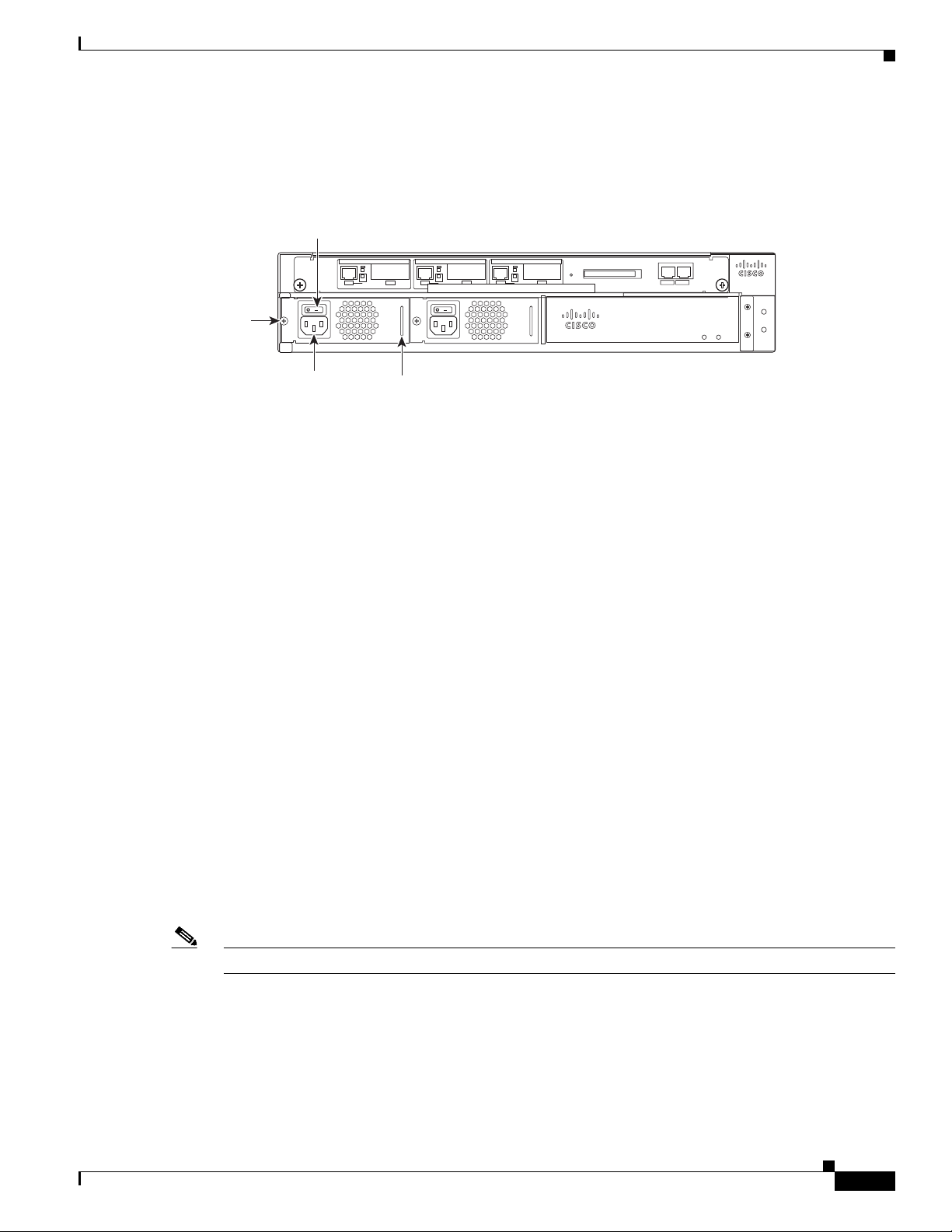
The Cisco uBR7225VXR power supply device does not have a cable retention clip.
Figure 1 Cisco uBR7225VXR AC-Input Power Supply
Power
switch
uBR7225-VXR
Captive
installation
screw
AC-input
receptacle
Handle
The Cisco uBR7225VXR power supply shuts itself down when the input AC voltage, the output DC
voltage, or the internal temperature of the chassis exceeds allowable tolerances. When this occurs, one
or both of the power supply front panel LEDs will turn red. The Cisco uBR7225VXR power supply must
then be reset by manually switching the power switch off and then back on to allow it to recover.
Cisco uBR7246 and Cisco uBR7246VXR
The power supply contains a main power switch, OK LED, and either an AC-input power receptacle, or
two hardwired DC-input power leads and three M5 grounding connectors (depending on the type of
installed power supply). Adjacent to the lower power supply bay, two M5 chassis grounding receptacles
provide a chassis ground connection for electrostatic discharge (ESD) equipment or a two-hole
grounding lug for the AC-input power supplies.
The Cisco uBR7246VXR and Cisco uBR7246 support an optional, second power supply for load sharing
and power redundancy. If you purchased a Cisco uBR7246VXR or Cisco uBR7246 and you want to
install a second power supply, you must order the second power supply separately.
A handle on the AC-input power supply unit provides a grip point for removing and replacing the power
supply. (Figure 2 shows the faceplate of the Cisco uBR7246VXR and Cisco uBR7246 AC-input power
supply.)
Two captive installation screws secure the power supply to the chassis and seat the power supply in the
router midplane. A Power OK LED indicates that the power supply is delivering +5 VDC to the router
midplane.
uBR7225-VXR
270538
78-4848-06
The AC-input power supply has a receptacle for an AC-input power cable. A modular power cable
connects the AC-input power supply to the site AC power source. A cable-retention clip secures the
power cable to the AC-input power supply.
Note Each AC-input power supply has an electrical current rating of 7A.
Cisco uBR7200 Series Universal Broadband Router AC Power Supply Replacement Instructions
3
Page 4
Installation Prerequisites
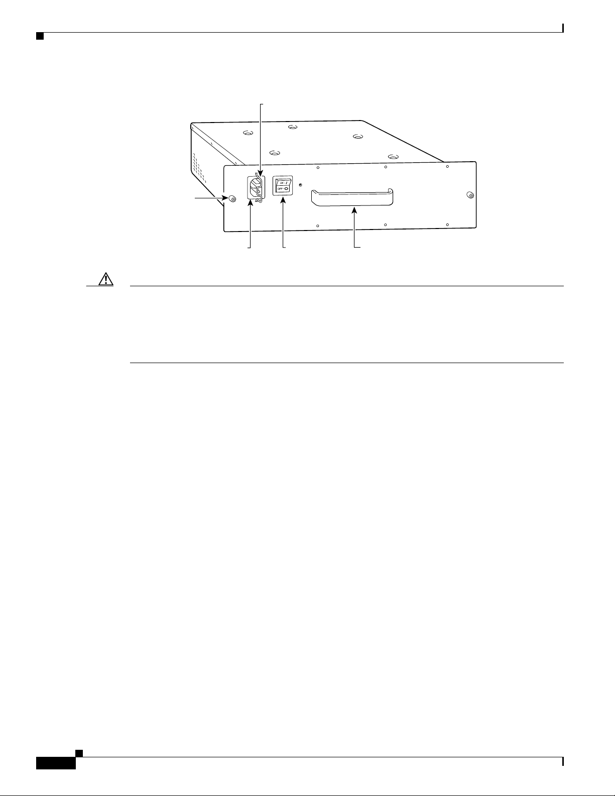
Figure 2 Cisco uBR7246 and Cisco uBR7246VXR AC-Input Power Supply
Captive installation screw
Cable-retention clip
H10074
AC-input receptacle
Caution When the input power to Cisco uBR7246 universal broadband router power supply is disconnected or
lost, the power supply enters a reset cycle for 10 seconds. Wait at least 10 seconds or move the power
switch from one position to the other to restart the power supply. For example, if the power supply was
on when the power was disconnected or lost, move the power switch to the off position then back to the
on position. If you do not wait the full 10 seconds or move the power switch from one position to the
other, the power supply does not restart.
Installation Prerequisites
This section provides a list of parts and tools you need to remove and replace the AC-input power supply
in the Cisco uBR7200 series routers. This section also includes safety and ESD-prevention guidelines to
help you avoid injury to yourself and damage to the equipment.
Parts and Tools
You need the following tools and parts to remove and replace the AC-input power supply in the
Cisco uBR7200 series. If you need additional equipment, contact a service representative for ordering
information.
Power switch
Handle
• An AC-input power supply
• Number 2 Phillips screwdriver
• 3/16-inch flat-blade screwdriver
• Several cable ties (if the router is mounted in an equipment rack)
Safety Guidelines
Following are safety guidelines that you should follow when working with any equipment that connects
to electrical power or telephone wiring.
Cisco uBR7200 Series Universal Broadband Router AC Power Supply Replacement Instructions
4
78-4848-06
Page 5

Safety Warnings
Safety warnings appear throughout this publication in procedures that, if performed incorrectly, might
harm you. A warning symbol precedes each warning statement.
Warning Definition
Installation Prerequisites
Warning
This warning symbol means danger. You are in a situation that could cause bodily injury. Before you
work on any equipment, be aware of the hazards involved with electrical circuitry and be familiar
with standard practices for preventing accidents. To see translations of the warnings that appear in
this publication, refer to the Regulatory Compliance and Safety Information document that
accompanied this device.
Waarschuwing Dit waarschuwingssymbool betekent gevaar. U verkeert in een situatie die lichamelijk
letsel kan veroorzaken. Voordat u aan enige apparatuur gaat werken, dient u zich bewust te zijn van de
bij elektrische schakelingen betrokken risico's en dient u op de hoogte te zijn van standaard maatregelen
om ongelukken te voorkomen. Voor vertalingen van de waarschuwingen die in deze publicatie
verschijnen, kunt u het document Regulatory Compliance and Safety Information (Informatie over
naleving van veiligheids- en andere voorschriften) raadplegen dat bij dit toestel is ingesloten.
Varoitus Tämä varoitusmerkki merkitsee vaaraa. Olet tilanteessa, joka voi johtaa ruumiinvammaan.
Ennen kuin työskentelet minkään laitteiston parissa, ota selvää sähkökytkentöihin liittyvistä vaaroista ja
tavanomaisista onnettomuuksien ehkäisykeinoista. Tässä julkaisussa esiintyvien varoitusten käännökset
löydät laitteen mukana olevasta Regulatory Compliance and Safety Information -kirjasesta (määräysten
noudattaminen ja tietoa turvallisuudesta).
Attention Ce symbole d'avertissement indique un danger. Vous vous trouvez dans une situation pouvant
causer des blessures ou des dommages corporels. Avant de travailler sur un équipement, soyez conscient
des dangers posés par les circuits électriques et familiarisez-vous avec les procédures couramment
utilisées pour éviter les accidents. Pour prendre connaissance des traductions d’avertissements figurant
dans cette publication, consultez le document Regulatory Compliance and Safety Information
(Conformité aux règlements et consignes de sécurité) qui accompagne cet appareil.
Warnung Dieses Warnsymbol bedeutet Gefahr. Sie befinden sich in einer Situation, die zu einer
Körperverletzung führen könnte. Bevor Sie mit der Arbeit an irgendeinem Gerät beginnen, seien Sie sich
der mit elektrischen Stromkreisen verbundenen Gefahren und der Standardpraktiken zur Vermeidung
von Unfällen bewußt. Übersetzungen der in dieser Veröffentlichung enthaltenen Warnhinweise finden
Sie im Dokument Regulatory Compliance and Safety Information (Informationen zu behördlichen
Vorschriften und Sicherheit), das zusammen mit diesem Gerät geliefert wurde.
78-4848-06
Avvertenza Questo simbolo di avvertenza indica un pericolo. La situazione potrebbe causare infortuni
alle persone. Prima di lavorare su qualsiasi apparecchiatura, occorre conoscere i pericoli relativi ai
circuiti elettrici ed essere al corrente delle pratiche standard per la prevenzione di incidenti. La
traduzione delle avvertenze riportate in questa pubblicazione si trova nel documento Regulatory
Compliance and Safety Information (Conformità alle norme e informazioni sulla sicurezza) che
accompagna questo dispositivo.
Advarsel Dette varselsymbolet betyr fare. Du befinner deg i en situasjon som kan føre til personskade.
Før du utfører arbeid på utstyr, må du vare oppmerksom på de faremomentene som elektriske kretser
innebærer, samt gjøre deg kjent med vanlig praksis når det gjelder å unngå ulykker. Hvis du vil se
Cisco uBR7200 Series Universal Broadband Router AC Power Supply Replacement Instructions
5
Page 6

Installation Prerequisites
oversettelser av de advarslene som finnes i denne publikasjonen, kan du se i dokumentet Regulatory
Compliance and Safety Information (Overholdelse av forskrifter og sikkerhetsinformasjon) som ble
levert med denne enheten.
Aviso Este símbolo de aviso indica perigo. Encontra-se numa situação que lhe poderá causar danos
físicos. Antes de começar a trabalhar com qualquer equipamento, familiarize-se com os perigos
relacionados com circuitos eléctricos, e com quaisquer práticas comuns que possam prevenir possíveis
acidentes. Para ver as traduções dos avisos que constam desta publicação, consulte o documento
Regulatory Compliance and Safety Information (Informação de Segurança e Disposições Reguladoras)
que acompanha este dispositivo.
¡Advertencia! Este símbolo de aviso significa peligro. Existe riesgo para su integridad física. Antes de
manipular cualquier equipo, considerar los riesgos que entraña la corriente eléctrica y familiarizarse con
los procedimientos estándar de prevención de accidentes. Para ver una traducción de las advertencias
que aparecen en esta publicación, consultar el documento titulado Regulatory Compliance and Safety
Information (Información sobre seguridad y conformidad con las disposiciones reglamentarias) que se
acompaña con este dispositivo.
Varning! Denna varningssymbol signalerar fara. Du befinner dig i en situation som kan leda till
personskada. Innan du utför arbete på någon utrustning måste du vara medveten om farorna med
elkretsar och känna till vanligt förfarande för att förebygga skador. Se förklaringar av de varningar som
förkommer i denna publikation i dokumentet Regulatory Compliance and Safety Information
(Efterrättelse av föreskrifter och säkerhetsinformation), vilket medföljer denna anordning.
Electrical Equipment Guidelines
Follow these basic guidelines when working with any electrical equipment:
• Before beginning any procedures requiring access to the chassis interior, locate the emergency
power-off switch for the room in which you are working.
• Disconnect all power and external cables before moving a chassis.
• Do not work alone if potentially hazardous conditions exist.
• Never assume that power has been disconnected from a circuit; always check.
• Do not perform any action that creates a potential hazard to people or makes the equipment unsafe.
• Carefully examine your work area for possible hazards such as moist floors, ungrounded power
extension cables, and missing safety grounds.
Telephone Wiring Guidelines
Use the following guidelines when working with any equipment that is connected to telephone wiring or
to other network cabling:
• Never install telephone wiring during a lightning storm.
• Never install telephone jacks in wet locations unless the jack is specifically designed for wet
locations.
• Never touch uninsulated telephone wires or terminals unless the telephone line has been
disconnected at the network interface.
• Use caution when installing or modifying telephone lines.
Cisco uBR7200 Series Universal Broadband Router AC Power Supply Replacement Instructions
6
78-4848-06
Page 7

Preventing Electrostatic Discharge Damage
Electrostatic discharge (ESD) damages equipment and impairs electrical circuitry. ESD occurs when
printed circuit boards are improperly handled and results in complete or intermittent failures.
The I/O controller, network processing engine, cable modem cards, and port adapters consist of a printed
circuit board that is fixed in a metal carrier. Electromagnetic interference (EMI) shielding, connectors,
and handle are integral components of the carrier. Handle the I/O controller, network processing engine,
cable modem cards, and port adapters by their carrier edges and handle only; never touch the printed
circuit board components or connector pins.
Although the metal carrier helps to protect the printed circuit boards from ESD, wear a preventive
antistatic strap whenever handling the network processing engine, I/O controller, cable modem cards, or
port adapters. Ensure that the strap makes good skin contact, and connect the strap’s clip to an unpainted
chassis surface to safely channel unwanted ESD voltages to ground. If no wrist strap is available, ground
yourself by touching the unpainted metal part of the chassis.
Caution Make sure to tighten the captive installation screws on the network processing engine, cable modem
cards, and I/O controller (use a number 2 Phillips screwdriver). These screws prevent accidental
removal, provide proper grounding for the router, and help to ensure that the network processing engine,
cable modem cards, and I/O controller are properly seated in the router midplane.
Installation Prerequisites
Following are guidelines for preventing ESD damage:
• Always use an ESD wrist strap or ankle strap when installing or replacing the I/O controller, network
processing engine, or port adapters. Ensure that the ESD strap makes contact with your skin.
• Handle the I/O controller, network processing engine, or port adapters by their metal carrier edges
and handles only; avoid touching the printed circuit board components or any connector pins.
• When removing the I/O controller, network processing engine, or port adapters, place them on an
antistatic surface with the printed circuit board components facing upward, or in a static shielding
bag. If you are returning an I/O controller, network processing engine, or port adapter to the factory,
immediately place it in a static shielding bag.
Caution Periodically check the resistance value of the antistatic strap. The measurement should be within the
range of 1 and 10 megohms (Mohms).
Ensuring Easy Access to the Router
If your Cisco uBR7200 series router is installed in a standard 19-inch-wide, four-post equipment rack or
telco-type equipment rack, cables from other equipment in the rack might obstruct access to the rear of
the router. Also, rack power strips or other permanent fixtures might obstruct access to the router. Review
the following guidelines to ensure easy access to the rear of the router when it is installed in a rack. If
the router is not installed in a rack, or if you already have clear access to the rear of the router, proceed
to the “Removing and Replacing an AC-Input Power Supply” section on page 8.
Use the following guidelines to ensure easy access to the rear of the router when it is installed in a rack:
78-4848-06
• Ensure that you have at least three to four feet of working space at the rear of the router.
• If cables from other equipment in the rack fall in front of the rear end of the router, carefully gather
the cables (using care not to strain them) and use cable ties to anchor them away from the rear of the
router.
Cisco uBR7200 Series Universal Broadband Router AC Power Supply Replacement Instructions
7
Page 8

Removing and Replacing an AC-Input Power Supply
• If access to the rear of the router is partially blocked by a power strip or some other permanent rack
fixture, detach the router from the rack and carefully slide it forward until there is enough clearance
to remove the power supply, the fan tray, the network processing engine, and the subchassis from
the router. Detailed steps for detaching the router from the rack are contained in the following
section, “Removing and Replacing an AC-Input Power Supply.”
Caution Make sure that at least one other person is available to support the front of the router as you slide it out
from the rack and, if necessary, to continue to support it while you remove and insert the power supply,
network processing engine, or subchassis.
Removing and Replacing an AC-Input Power Supply
The following sections explain how to remove and replace an AC-input power supply in a
Cisco uBR7200 series router for a single power supply configuration and a dual power supply
configuration.
Caution When the input power to a Cisco uBR7200 series power supply is disconnected or lost, the power supply
will enter a reset cycle for 90 seconds. Wait at least 90 seconds or move the power switch from one
position to the other to restart the power supply. For example, if the power supply was ON when the
power was disconnected or lost, move the power switch to the OFF position then back to the ON position.
If you do not wait the full 90 seconds or move the power switch from one position to the other, the power
supply will not restart. This caution note does not apply to the Cisco uBR7225VXR power supply.
Single Power Supply Configuration
Removing and replacing the AC-input power supply in a single power supply configuration involves the
following tasks:
• Powering Down the Router, page 8
• Disconnecting AC-Input Power, page 9
• Removing the AC-Input Power Supply, page 10
• Installing the AC-Input Power Supply, page 11
• Reconnecting AC-Input Power, page 12
• Powering Up the Router, page 13
These tasks are described in detail in the following subsections.
Powering Down the Router
Note Before powering down the router, use the copy running-config startup-config command to save the
router’s running configuration to nonvolatile memory.
Step 1 Facing the rear of the router, place the power switch (on the power supply) in the OFF (O) position.
Repeat this action if a second power supply is installed in the router.
Cisco uBR7200 Series Universal Broadband Router AC Power Supply Replacement Instructions
8
78-4848-06
Page 9

Step 2 Observe the following items:
• The green OK LED on the power supply goes off.
• The fans stop operating.
• The LEDs on the I/O controller go off.
• The LEDs on the port adapters go off.
• The LEDs on the cable modem cards go off.
This completes the procedure for powering down the router. Proceed to the following section
“Disconnecting AC-Input Power.”
Disconnecting AC-Input Power
Removing and Replacing an AC-Input Power Supply
Warning
Do not touch the power supply when the power cord is connected. For systems with a power switch,
line voltages are present within the power supply even when the power switch is off and the power
cord is connected. For systems without a power switch, line voltages are present within the power
supply when the power cord is connected.
Warning
Before working on equipment that is connected to power lines, remove jewelry (including rings,
necklaces, and watches). Metal objects will heat up when connected to power and ground and can
cause serious burns or weld the metal object to the terminals.
Step 1 Unplug the input power cable from the power source.
Step 2 Push the cable-retention clip that secures the input power cable to the router power supply to the left.
Step 3 Unplug the other end of the input power cable from the power supply. (See Figure 3.)
Note The Cisco uBR7225VXR power supply device does not have a cable retention clip.
Figure 3 Disconnecting Power from a Cisco uBR7200 Series AC-Input Power Supply
Cable-retention clip
78-4848-06
Power
receptacle
Captive
installation
screw
Power
switch
Handle
AC power cable
Cisco uBR7200 Series Universal Broadband Router AC Power Supply Replacement Instructions
H10073
9
Page 10

Removing and Replacing an AC-Input Power Supply
This completes the procedure for disconnecting AC-input power. Proceed to the following section,
“Removing the AC-Input Power Supply.”
Removing the AC-Input Power Supply
Step 1 Using a number 2 Phillips screwdriver, loosen the two captive installation screws on the faceplate of the
power supply. (See Figure 4.) Use the flat head or Phillips screw driver to fasten or losen the single screw
on the uBR7225VXR power supply.
Note If you are removing a power supply filler plate in preparation to install a second power supply, make sure
you remove both the filler plate and its attached air dam from the second power supply bay.
If the router is not installed in a standard four-post or telco rack, skip to Step 5. If the router is installed
in a rack, determine if any permanent rack fixtures, such as a power strip, are obstructing access to the
power supply. If a rack fixture is obstructing access to the power supply, proceed to Step 2.
Figure 4 Captive Installation Screws and Handle on the AC-Input Power Supply
Captive installation screw
(on both sides of power supply)
Handle
H11310
Step 2
Using a 3/16-inch flat-blade screwdriver, loosen the screws that secure the router to the front mounting
strips of the rack.
Step 3 Position at least one person in front of the rack to support the front underside of the router.
Step 4 From the rear of the rack, carefully push the front of the router out of the rack until there is enough
clearance to remove the power supply from the router.
Step 5 Grasp the power supply handle and pull the AC-input power supply from the router.
Caution To maintain agency compliance requirements and meet EMI emissions standards for the
Cisco uBR7246VXR and Cisco uBR7246 with a single power supply, the power supply filler plate and
its attached air dam must remain in the power supply adjacent to the installed power supply. Do not
remove this filler plate or the attached air dam from the router unless you intend to install a redundant
power supply.
10
This completes the procedure for removing the AC-input power supply from a Cisco uBR7200 series
router. Proceed to the following section, “Installing the AC-Input Power Supply.”
Cisco uBR7200 Series Universal Broadband Router AC Power Supply Replacement Instructions
78-4848-06
Page 11

Installing the AC-Input Power Supply
Step 1 Make sure the power switch on the power supply is in the OFF (O) position.
Note If you are adding a second power supply to a Cisco uBR7246VXR or Cisco uBR7246 that previously
only had one power supply installed, make sure the power supply filler plate and its attached air dam
have been removed from the power supply bay.
Step 2 Grasp the power supply handle with one hand and place your other hand underneath the power supply
for support. (See Figure 5.)
Figure 5 Holding the AC-Input Power Supply
Removing and Replacing an AC-Input Power Supply
Connector
Handle
H10095
Step 3
Step 4 Slide the power supply completely in to the power supply bay until its faceplate is flush with the router
Align the power supply to the power supply bay.
rear panel.
Caution When inserting a power supply into the router, do not use unnecessary force; slamming the power supply
into the bay can damage the connectors on the rear of the power supply and on the midplane.
Step 5 Seat the power supply in the router by tightening the captive installation screws with a number 2 Phillips
screwdriver.
Note The power supply is not fully seated in the router midplane until you tighten the captive installation
screws. Use the flat head or Phillips screw driver to fasten or losen the single screw on the uBR7225VXR
power supply.
Step 6 If there is no second power supply, replace the filler plate and its attached air dam on the empty power
supply bay. Using a number 2 Phillips screwdriver, tighten the filler plate captive installation screws.
78-4848-06
Cisco uBR7200 Series Universal Broadband Router AC Power Supply Replacement Instructions
11
Page 12

Removing and Replacing an AC-Input Power Supply
Step 7 If you pushed the router from the rack, slowly guide the router back into the rack.
Step 8 Use a 3/16-inch flat-blade screwdriver to tighten the screws that secure the router to the front mounting
strips of the rack.
Caution To maintain agency compliance requirements and meet EMI emissions standards for the
Cisco uBR7246VXR and Cisco uBR7246 with a single power supply, the power supply filler plate and
its attached air dam must remain in the power supply adjacent to the installed power supply. Do not
remove this filler plate or the attached air dam from the router unless you intend to install a redundant
power supply.
This completes the procedures for installing the AC-input power supply in the router. Proceed to the
following section, “Reconnecting AC-Input Power.”
Reconnecting AC-Input Power
Warning
Never defeat the ground conductor or operate the equipment in the absence of a suitably installed
ground conductor. Contact the appropriate electrical inspection authority or an electrician if you are
uncertain that suitable grounding is available.
Step 1 At the rear of the router, check that the power switch on the power supply is in the OFF (O) position.
Step 2 Push the cable-retention clip to the left, away from the AC receptacle, and plug in the power cable.
Step 3 Secure the cable in the power supply AC receptacle by pushing the cable-retention clip to the right until
it snaps around the connector. The cable-retention clip provides strain relief for the AC power cable. (See
Figure 6.)
Note The Cisco uBR7225VXR power supply device does not have a cable retention clip.
Figure 6 Connecting AC-Input Power to a Cisco uBR7200 Series Router
Cable-retention clip
Power receptacle
Captive installation screw
Power switch
12
AC power cable
Step 4
Cisco uBR7200 Series Universal Broadband Router AC Power Supply Replacement Instructions
Plug the AC power supply cable into the AC power source.
Handle
H11322
78-4848-06
Page 13

Note Each uBR7246 AC-input power supply has an electrical current rating of 7A. The uBR7225 AC-input
power supply is 4A.
This completes the steps for reconnecting AC-input power to a Cisco uBR7200 series router. Proceed to
the following section, “Powering Up the Router.”
Powering Up the Router
Step 1 Check for the following:
• Each port adapter is inserted in its slot, and the port adapter retention clip is in the locked
Note The Cisco uBR7225VXR router does not support port adapters or the I/O controller. The
• Each cable modem card is inserted in its slot, and its respective captive installation screws are
• The network processing engine and the I/O controller are inserted in their respective slots, and
• All network interface cables are connected to the port adapters.
Removing and Replacing an AC-Input Power Supply
position.
Cisco uBR7225VXR power supply device does not have a cable retention clip..
tightened.
their captive installation screws are tightened.
• A Flash memory card is installed in its PCMCIA slot (if present).
• Each AC-input power cable is connected and secured with the cable-retention clip.
• The console terminal is turned on.
Step 2 At the rear of the router, place the power switch on the power supply in the ON (|) position. Repeat this
step if a second power supply is installed in the router. The green OK LED on the power supply goes on.
Step 3 Listen for the fans; you should immediately hear them operating.
Step 4 During the boot process, observe the system LEDs. The LEDs on most of the port adapters and cable
modem cards go on and off randomly. Some might go on, go out, and go on again for a short time. On
the I/O controller, the IO Power OK LED goes on immediately.
Step 5 Observe the initialization process. When the system boot is complete (after a few seconds), the network
processing engine begins to initialize the port adapters and the I/O controller. During this initialization,
the LEDs on each port adapter behave differently (most flash on and off). The enabled LED on each port
adapter goes on when initialization is completed, and the console screen displays a script and system
banner similar to the following:
Cisco Internetwork Operating System Software
IOS (tm) uBR7200 Software (uBR7200-I-M), Version 11.3(2)XA1 [kpfjrgiu 100]
Copyright (c) 1986-1998 by cisco Systems, Inc.
Compiled Sun 09-Mar-98 04:10 by smith
This completes the procedures for powering up the router. This also completes the procedure for
replacing the AC-input power supply in a single Cisco uBR7200 series power supply configuration.
If you have questions or need assistance, see the “Obtaining Documentation and Submitting a Service
Request” section on page 17. Otherwise, if your Cisco uBR7246VXR or Cisco uBR7246 has a dual
power supply configuration, proceed to the following section, “Dual Power Supply Configuration in the
Cisco uBR7200 Series Routers.”
78-4848-06
Cisco uBR7200 Series Universal Broadband Router AC Power Supply Replacement Instructions
13
Page 14

Removing and Replacing an AC-Input Power Supply
Dual Power Supply Configuration in the Cisco uBR7200 Series Routers
Removing and replacing an AC-input power supply in a dual power supply configuration in the or Cisco
uBR7200 series routers involves the following tasks:
• Turning OFF the Power Supply, page 14
• Disconnecting AC-Input Power, page 14
• Removing the AC-Input Power Supply, page 14
• Installing the AC-Input Power Supply, page 15
• Reconnecting AC-Input Power, page 12
• Turning ON the Power Supply, page 16
These tasks are described in detail in the following subsections.
Turning OFF the Power Supply
Step 1 Facing the rear of the router, place the power switch (on the power supply) in the OFF (O) position.
Step 2 Observe the following items:
• The green OK LED on the power supply goes off
• The second power supply maintains full system power (the system continues to operate as
normal)
This completes the procedure for turning off the power supply. Proceed to the following section
“Disconnecting AC-Input Power.”
Disconnecting AC-Input Power
Step 1 Unplug the input power cable from the power source.
Step 2 Push the cable-retention clip that secures the input power cable to the router power supply to the left.
Note The Cisco uBR7225VXR power supply device does not have a cable retention clip.
Step 3 Unplug the other end of the input power cable from the power supply.
This completes the procedure for disconnecting AC input power. Proceed to the following section,
“Removing the AC-Input Power Supply.”
Removing the AC-Input Power Supply
14
Step 1 Using a number 2 Phillips screwdriver, loosen the two captive installation screws on the faceplate of the
power supply. (See Figure 4.) Use the flat head or Phillips screw driver to fasten or losen the single screw
on the uBR7225VXR power supply.
If the router is not installed in a standard four-post or telco rack, skip to Step 5. If the router is installed
in a rack, determine if any permanent rack fixtures, such as a power strip, are obstructing access to the
power supply. If a rack fixture is obstructing access to the power supply, proceed with Step 2.
Cisco uBR7200 Series Universal Broadband Router AC Power Supply Replacement Instructions
78-4848-06
Page 15

Step 2 Using a 3/16-inch flat-blade screwdriver, loosen the screws that secure the router to the front mounting
strips of the rack.
Step 3 Position at least one person in front of the rack to support the front underside of the router.
Step 4 From the rear of the rack, carefully push the front of the router out of the rack until there is enough
clearance to remove the power supply from the router.
Step 5 Grasp the power supply handle and pull the AC-input power supply from the router.
This completes the procedure for removing the AC-input power supply. Proceed to the following section,
“Installing the AC-Input Power Supply.”
Installing the AC-Input Power Supply
Step 1 Make sure the power switch on the power supply is in the OFF (O) position.
Step 2 Grasp the power supply handle with one hand and place your other hand underneath the power supply
for support. (See Figure 5.)
Note If you are adding a second power supply to a Cisco uBR7246VXR or Cisco uBR7246 that previously
only had one power supply installed, make sure the power supply filler plate and its attached air dam
have been removed from the power supply bay.
Removing and Replacing an AC-Input Power Supply
Step 3 Align the power supply to the power supply bay.
Step 4 Slide the power supply completely in to the power supply bay until its faceplate is flush with the router
rear panel.
Caution When inserting a power supply into the router, do not use unnecessary force; slamming the power supply
into the bay can damage the connectors on the rear of the supply and on the midplane.
Step 5 Seat the power supply in the router by tightening its captive installation screws with a number 2 Phillips
screwdriver. Use the flat head or Phillips screw driver to fasten or losen the single screw on the
uBR7225VXR power supply.
Note The power supply is not fully seated in the router midplane until you tighten the captive installation
screws.
Step 6 If you pushed the router forward in the rack, slowly guide the router back into the rack.
Step 7 Use a 3/16-inch flat-blade screwdriver to tighten the screws that secure the router to the front mounting
strips of the rack.
This completes the procedures for installing the AC-input power supply in the router. Proceed to the
following section, “Reconnecting AC-Input Power”.
Reconnecting AC-Input Power
78-4848-06
Step 1 At the rear of the router, check that the power switch on the power supply is in the OFF (O) position.
Step 2 Push the cable-retention clip to the left, away from the AC receptacle, and plug in the power cable.
Cisco uBR7200 Series Universal Broadband Router AC Power Supply Replacement Instructions
15
Page 16

Removing and Replacing an AC-Input Power Supply
Note The Cisco uBR7225VXR power supply device does not have a cable retention clip.
Step 3 Secure the cable in the power supply AC receptacle by pushing the cable-retention clip to the right until
it snaps around the connector. The cable-retention clip provides strain relief for the AC power cable.
Figure 7 Cisco uBR7200 Series Power Supply AC Receptacles and Power Switch
Captive installation screw
Cable-retention clip
H10074
AC-input receptacle
Step 4
Plug the AC power supply cable into the AC power source.
Note Each uBR7246 AC-input power supply operating at 120 VAC requires a minimum of 7A while
the uBR7225 AC-input power supply requires a minimum of 4A.
Step 5 Repeat Step 1 through Step 4 if a second power supply is installed.
This completes the steps for reconnecting AC-input power. Proceed to the following section, “Turning
ON the Power Supply.”
Turning ON the Power Supply
Step 1 Place the power switch on the newly installed power supply in the ON (|) position.
Step 2 Observe the following:
• The green OK LED on the power supply goes on.
• The system continues to operate as normal.
This completes the procedures for turning on the power supply. This also completes the procedure for
removing and replacing the AC-input power supply in the Cisco uBR7200 series routers Cisco uBR7246
with a dual power supply configuration.
Power switch
Handle
16
Cisco uBR7200 Series Universal Broadband Router AC Power Supply Replacement Instructions
78-4848-06
Page 17

Obtaining Documentation and Submitting a Service Request
Obtaining Documentation and Submitting a Service Request
For information on obtaining documentation, submitting a service request, and gathering additional
information, see the monthly What’s New in Cisco Product Documentation, which also lists all new and
revised Cisco technical documentation, at:
http://www.cisco.com/en/US/docs/general/whatsnew/whatsnew.html
Subscribe to the What’s New in Cisco Product Documentation as a Really Simple Syndication (RSS) feed
and set content to be delivered directly to your desktop using a reader application. The RSS feeds are a free
service and Cisco currently supports RSS version 2.0.
CCDE, CCENT, Cisco Eos, Cisco StadiumVision, the Cisco logo, DCE, and Welcome to the Human Network are trademarks; Changing the Way We
Work, Live, Play, and Learn is a service mark; and Access Registrar, Aironet, AsyncOS, Bringing the Meeting To You, Catalyst, CCDA, CCDP, CCIE,
CCIP, CCNA, CCNP, CCSP, CCVP, Cisco, the Cisco Certified Internetwork Expert logo, Cisco IOS, Cisco Press, Cisco Systems, Cisco Systems
Capital, the Cisco Systems logo, Cisco Unity, Collaboration Without Limitation, Enterprise/Solver, EtherChannel, EtherFast, EtherSwitch, Event
Center, Fast Step, Follow Me Browsing, FormShare, GigaDrive, HomeLink, Internet Quotient, IOS, iPhone, iQ Expertise, the iQ logo, iQ Net
Readiness Scorecard, iQuick Study, IronPort, the IronPort logo, LightStream, Linksys, MediaTone, MeetingPlace, MGX, Networkers, Networking
Academy, Network Registrar, PCNow, PIX, PowerPanels, ProConnect, ScriptShare, SenderBase, SMARTnet, Spectrum Expert, StackWise, The
Fastest Way to Increase Your Internet Quotient, TransPath, WebEx, and the WebEx logo are registered trademarks of Cisco Systems, Inc. and/or its
affiliates in the United States and certain other countries.
All other trademarks mentioned in this document or Website are the property of their respective owners. The use of the word partner does not imply
a partnership relationship between Cisco and any other company. (0803R)
Any Internet Protocol (IP) addresses used in this document are not intended to be actual addresses. Any examples, command display output, and
figures included in the document are shown for illustrative purposes only. Any use of actual IP addresses in illustrative content is unintentional and
coincidental.
© 2008 Cisco Systems, Inc. All rights reserved.
78-4848-06
Cisco uBR7200 Series Universal Broadband Router AC Power Supply Replacement Instructions
17
Page 18

Obtaining Documentation and Submitting a Service Request
18
Cisco uBR7200 Series Universal Broadband Router AC Power Supply Replacement Instructions
78-4848-06
 Loading...