

Page 1

4038767 Rev A
Cisco Model TES301 IP Managed
Services Home Gateway User Guide
Page 2

Page 3

Please Read
Important
Please read this entire guide. If this guide provides installation or operation
instructions, give particular attention to all safety statements included in this guide.
Page 4

Notices
Trademark Acknowledgments
Cisco and the Cisco logo are trademarks or registered trademarks of Cisco and/or its
affiliates in the U.S. and other countries. A listing of Cisco's trademarks can be found
at www.cisco.com/go/trademarks.
Third party trademarks mentioned are the property of their respective owners.
The use of the word partner does not imply a partnership relationship between
Cisco and any other company. (1009R)
The Wi-Fi Protected Setup mark is a mark of the Wi-Fi Alliance. Wi-Fi Protected
Setup is a trademark of the Wi-Fi Alliance.
Disclaimer
The maximum performance for wireless is derived from IEEE Standard 802.11
specifications. Actual performance can vary, including lower wireless network
capacity, data throughput rate, range and coverage. Performance depends on many
factors, conditions and variables, including distance from the access point, volume of
network traffic, building materials and construction, operating system used, mix of
wireless products used, interference and other adverse conditions.
Publication Disclaimer
Cisco Systems, Inc. assumes no responsibility for errors or omissions that may
appear in this publication. We reserve the right to change this publication at any
time without notice. This document is not to be construed as conferring by
implication, estoppel, or otherwise any license or right under any copyright or
patent, whether or not the use of any information in this document employs an
invention claimed in any existing or later issued patent.
Copyright
© 2011 Cisco and/or its affiliates. All rights reserved. Printed in the United States of
America.
Information in this publication is subject to change without notice. No part of this
publication may be reproduced or transmitted in any form, by photocopy,
microfilm, xerography, or any other means, or incorporated into any information
retrieval system, electronic or mechanical, for any purpose, without the express
permission of Cisco Systems, Inc.
Page 5
Notice to Installers
The servicing instructions in this notice are for use by qualified service personnel only. To reduce the
risk of electric shock, do not perform any servicing other than that contained in the operating
instructions, unless you are qualified to do so.
Notice à l’attention des installateurs de réseaux câblés
Les instructions relatives aux interventions d’entretien, fournies dans la présente notice, s’adressent
exclusivement au personnel technique qualifié. Pour réduire les risques de chocs électriques, n’effectuer
aucune intervention autre que celles décrites dans le mode d'emploi et les instructions relatives au
fonctionnement, à moins que vous ne soyez qualifié pour ce faire.
Mitteilung für CATV-Techniker
Die in dieser Mitteilung aufgeführten Wartungsanweisungen sind ausschließlich für qualifiziertes
Fachpersonal bestimmt. Um die Gefahr eines elektrischen Schlags zu reduzieren, sollten Sie keine
Wartungsarbeiten durchführen, die nicht ausdrücklich in der Bedienungsanleitung aufgeführt sind,
außer Sie sind zur Durchführung solcher Arbeiten qualifiziert.
Page 6
Aviso a los instaladores de sistemas CATV
Las instrucciones de reparación contenidas en el presente aviso son para uso exclusivo por parte de
personal de mantenimiento cualificado. Con el fin de reducir el riesgo de descarga eléctrica, no realice
ninguna otra operación de reparación distinta a las contenidas en las instrucciones de funcionamiento, a
menos que posea la cualificación necesaria para hacerlo.
20080814_Installer800_Intl
Page 7

4038767 Rev A iii
Contents
Notice à l’attention des installateurs de réseaux câblés ........................................ 5
Mitteilung für CATV-Techniker ............................................................................... 5
Aviso a los instaladores de sistemas CATV ............................................................ 6
IMPORTANT SAFETY INSTRUCTIONS vii
Power Source Warning ........................................................................................... vii
Ground the Product ................................................................................................. vii
Protect the Product from Lightning ..................................................................... viii
Verify the Power Source from the On/Off Power Light ................................... viii
Eliminate AC Mains Overloads ............................................................................ viii
Provide Ventilation and Select a Location .......................................................... viii
Protect from Exposure to Moisture and Foreign Objects .................................. viii
Service Warnings .................................................................................................... viii
Check Product Safety ................................................................................................ ix
Protect the Product When Moving It ...................................................................... ix
Telephone Equipment Notice .................................................................................. ix
United States FCC Compliance x
Declaration of Conformity ......................................................................................... x
Canada EMI Regulation ............................................................................................. x
RF Exposure Statements ............................................................................................ x
CE Compliance xii
Declaration of Conformity with Regard to the EU Directive
1999/5/EC (R&TTE Directive) ............................................................................ xii
National Restrictions ...............................................................................................xiii
Antennas ................................................................................................................... xiv
About This Guide xv
Introduction ............................................................................................................... xv
Purpose ....................................................................................................................... xv
Audience .................................................................................................................... xv
Document Version .................................................................................................... xv
Page 8

Contents
iv 4038767 Rev A
Chapter 1 Introducing the TES301 IP Managed Services Home
Gateway 1
Benefits and Features............................................................................................................... 2
Highlights .................................................................................................................... 2
Simplified Connected Home ..................................................................................... 2
Personal Content Sharing and Storage .................................................................... 3
Application Environment .......................................................................................... 3
High-Speed Wireless Interfaces ................................................................................ 3
Phone Services ............................................................................................................. 3
Management and Troubleshooting .......................................................................... 4
What's on the Top Panel? ........................................................................................................ 5
What's on the Back Panel? ...................................................................................................... 7
What's on the Side Panel? ....................................................................................................... 8
What's on the Bottom Panel ................................................................................................... 9
Chapter 2 Installing the Home Gateway 11
Mounting the Home Gateway ............................................................................................. 12
Mounting the TES301 Horizontally ........................................................................ 12
Mounting the TES301 Vertically ............................................................................. 12
Connecting the Home Gateway ........................................................................................... 15
Chapter 3 Configuration and Operation of the TES301 19
Logging into the Home Gateway ........................................................................................ 20
Dashboard ............................................................................................................................... 21
Internet .................................................................................................................................... 22
VoIP Settings........................................................................................................................... 28
SIP ............................................................................................................................... 28
Service ......................................................................................................................... 31
Voice ........................................................................................................................... 33
Advanced ................................................................................................................... 35
Call Log ...................................................................................................................... 38
Wi-Fi ........................................................................................................................................ 40
Connect Devices ........................................................................................................ 42
Page 9

Contents
4038767 Rev A v
Home Address ........................................................................................................................ 44
Configure the DLNA Settings .............................................................................................. 45
Advanced Settings ................................................................................................................. 46
Chapter 4 Managing Digital Media 47
Using the Media Controller .................................................................................................. 48
Using the Media Server ......................................................................................................... 51
Chapter 5 Using the LCD 55
Get Familiar with the LCD Menus and Pages ................................................................... 56
Internet .................................................................................................................................... 57
Phone ....................................................................................................................................... 58
Wi-Fi ........................................................................................................................................ 60
Turn Wi-Fi Off or On ................................................................................................ 60
Initiate Wi-Fi Protection Setup ................................................................................ 62
Connection .............................................................................................................................. 65
Settings .................................................................................................................................... 66
Review Your Emergency 911 Address .................................................................. 67
Perform Factory Reset .............................................................................................. 68
Select Language Settings .......................................................................................... 69
Select LCD Display Orientation .............................................................................. 70
View Network Information ..................................................................................... 70
Use Network Tools ................................................................................................... 72
Reboot ......................................................................................................................... 73
View Router Information ......................................................................................... 74
View System Event Log ........................................................................................... 75
Set Up Time of Day Parameters .............................................................................. 75
App Store ................................................................................................................................ 77
Page 10

Page 11

IMPORTANT SAFETY INSTRUCTIONS
4038767 Rev A vii
IMPORTANT SAFETY INSTRUCTIONS
1)
Read these instructions.
2)
Keep these instructions.
3)
Heed all warnings.
4)
Follow all instructions.
5)
Do not use this apparatus near water.
6)
Clean only with dry cloth.
7)
Do not block any ventilation openings. Install in accordance with the manufacturer's
instructions.
8)
Do not install near any heat sources such as radiators, heat registers, stoves, or other
apparatus (including amplifiers) that produce heat.
9)
Do not defeat the safety purpose of the polarized or grounding-type plug. A
polarized plug has two blades with one wider than the other. A grounding-type
plug has two blades and a third grounding prong. The wide blade or the third
prong are provided for your safety. If the provided plug does not fit into your
outlet, consult an electrician for replacement of the obsolete outlet.
10)
Protect the power cord from being walked on or pinched particularly at plugs,
convenience receptacles, and the point where they exit from the apparatus.
11)
Only use attachments/accessories specified by the manufacturer.
12) Use only with the cart, stand, tripod, bracket, or table specified by the
manufacturer, or sold with the apparatus. When a cart is used, use caution
when moving the cart/apparatus combination to avoid injury from
tip-over.
13)
Unplug this apparatus during lightning storms or when unused for long periods of
time.
14)
Refer all servicing to qualified service personnel. Servicing is required when the
apparatus has been damaged in any way, such as a power-supply cord or plug is
damaged, liquid has been spilled or objects have fallen into the apparatus, the
apparatus has been exposed to rain or moisture, does not operate normally, or has
been dropped.
WARNING: Avoid electric shock and fire hazard! If this product connects to coaxial
cable wiring, be sure the cable system is grounded (earthed). Grounding provides
some protection against voltage surges and built-up static charges.
Power Source Warning
A label on this product indicates the correct power source for this product. Operate this product only
from an electrical outlet with the voltage and frequency indicated on the product label. If you are
uncertain of the type of power supply to your home or business, consult your service provider or your
local power company.
The AC inlet on the unit must remain accessible and operable at all times.
Ground the Product
Page 12

IMPORTANT SAFETY INSTRUCTIONS
viii 4038767 Rev A
WARNING: Avoid electric shock and fire hazard! Do not overload AC mains, outlets,
extension cords, or integral convenience receptacles. For products that require battery
power or other power sources to operate them, refer to the operating instructions for
those products.
WARNING: Avoid electric shock and fire hazard! Do not expose this product to
dripping or splashing liquids, rain, or moisture. Objects filled with liquids, such as
vases, should not be placed on this apparatus.
WARNING: Avoid electric shock and fire hazard! Unplug this product before cleaning.
Do not use a liquid cleaner or an aerosol cleaner. Do not use a magnetic/static cleaning
device (dust remover) to clean this product.
WARNING: Avoid electric shock and fire hazard! Never push objects through the
openings in this product. Foreign objects can cause electrical shorts that can result in
electric shock or fire.
WARNING: Avoid electric shock! Do not open the cover of this product. Opening or
removing the cover may expose you to dangerous voltages. If you open the cover, your
warranty will be void. This product contains no user-serviceable parts.
Protect the Product from Lightning
In addition to disconnecting the AC power from the wall outlet, disconnect the signal inputs.
Verify the Power Source from the On/Off Power Light
When the on/off power light is not illuminated, the apparatus may still be connected to the power
source. The light may go out when the apparatus is turned off, regardless of whether it is still plugged
into an AC power source.
Eliminate AC Mains Overloads
Provide Ventilation and Select a Location
Remove all packaging material before applying power to the product.
Do not place this apparatus on a bed, sofa, rug, or similar surface.
Do not place this apparatus on an unstable surface.
Do not install this apparatus in an enclosure, such as a bookcase or rack, unless the installation
provides proper ventilation.
Do not place entertainment devices (such as VCRs or DVDs), lamps, books, vases with liquids, or
other objects on top of this product.
Do not block ventilation openings.
Protect from Exposure to Moisture and Foreign Objects
Service Warnings
Page 13

IMPORTANT SAFETY INSTRUCTIONS
4038767 Rev A ix
Check Product Safety
CAUTION: To reduce the risk of fire, use only No. 26 AWG or larger
telecommunication line cord.
Upon completion of any service or repairs to this product, the service technician must perform safety
checks to determine that this product is in proper operating condition.
Protect the Product When Moving It
Always disconnect the power source when moving the apparatus or connecting or disconnecting
cables.
Telephone Equipment Notice
When using your telephone equipment, basic safety precautions should always be followed to reduce
the risk of fire, electric stock and injury to persons, including the following:
1. Do not use this product near water, for example, near a bath tub, wash bowl, kitchen sink or laundry
tub, in a wet basement or near a swimming pool.
2. Avoid using a telephone (other than a cordless type) during an electrical storm. There may be a
remote risk of electric shock from lightning.
3. Do not use the telephone to report a gas leak in the vicinity of the leak.
SAVE THESE INSTRUCTIONS
20090915_Modem No Battery_Safety
Page 14

United States FCC Compliance
x 4038767 Rev A
United States FCC Compliance
This device complies with Part 15 of FCC
Rules. Operation is subject to the following
two conditions: 1) the device may not cause
harmful interference, and 2) the device must
accept any interference received, including
interference that may cause undesired
operation.
Cisco® Model TES301 Managed Services
Home Gateway
Model(s): TES301
Manufactured by:
Cisco Systems, Inc.
5030 Sugarloaf Parkway
Lawrenceville, Georgia 30044 USA
Telephone: 770 236-1077
This device has been tested and found to comply with the limits for a Class B digital device,
pursuant to part 15 of the FCC Rules. These limits are designed to provide reasonable
protection against such interference in a Home installation. This equipment generates, uses,
and can radiate radio frequency energy. If not installed and used in accordance with the
instructions, it may cause harmful interference to radio communications. However, there is
no guarantee that interference will not occur in a particular installation. If this equipment
does cause harmful interference to radio or television reception, which can be determined by
turning the equipment OFF and ON, the user is encouraged to try to correct the interference
by one or more of the following measures:
Reorient or relocate the receiving antenna.
Increase the separation between the equipment and receiver.
Connect the equipment into an outlet on a circuit different from that to which the
receiver is connected.
Consult the service provider or an experienced radio/television technician for help.
Any changes or modifications not expressly approved by Cisco Systems, Inc., could void the
user's authority to operate the equipment.
The information shown in the FCC Declaration of Conformity paragraph below is a
requirement of the FCC and is intended to supply you with information regarding the FCC
approval of this device. The phone numbers listed are for FCC-related questions only and not
intended for questions regarding the connection or operation for this device. Please contact your
service provider for any questions you may have regarding the operation or installation of this device.
Declaration of Conformity
Canada EMI Regulation
This Class B digital apparatus complies with Canadian ICES-003.
Cet appareil numérique de la class B est conforme à la norme NMB-003 du Canada.
RF Exposure Statements
Note: This transmitter must not be co-located or operated in conjunction with any other
antenna or transmitter. This equipment should be installed and operated with a minimum
distance of 7.9 inches (20 cm) between the radiator and your body.
Page 15

United States FCC Compliance
4038767 Rev A xi
US
This system has been evaluated for RF exposure for humans in reference to ANSI C 95.1
(American National Standards Institute) limits. The evaluation was based in accordance with
FCC OET Bulletin 65C Rev A.01 in compliance with Part 2.1091 and Part 15.27. The minimum
separation distance from the antenna to general bystander is 7.9 inches (20 cm) to maintain
compliance.
Canada
This system has been evaluated for RF exposure for humans in reference to Canada Health
Code 6 (2009) limits. The evaluation was based on evaluation per RSS-102 Rev 4. The
minimum separation distance from the antenna to general bystander is 7.9 inches (20 cm) to
maintain compliance.
20100527 FCC DSL_Domestic
Page 16
CE Compliance
xii 4038767 Rev A
CE Compliance
Declaration of Conformity with Regard to the EU Directive 1999/5/EC
(R&TTE Directive)
This declaration is only valid for configurations (combinations of software, firmware and
hardware) supported or provided by Cisco Systems for use within the EU. The use of
software or firmware not supported or provided by Cisco Systems may result in the
equipment no longer being compliant with the regulatory requirements.
Page 17

CE Compliance
4038767 Rev A xiii
Note: The full declaration of conformity for this product can be found in the Declarations of
-1999/5/EC
Conformity and Regulatory Information section of the appropriate product hardware
installation guide, which is available on Cisco.com.
The following standards were applied during the assessment of the product against the
requirements of the Directive 1999/5/EC:
Radio: EN 300 328
EMC: EN 301 489-1 and EN 301 489-17
Safety: EN 60950 and EN 50385
The CE mark and class-2 identifier are affixed to the product and its packaging. This product
conforms to the following European directives:
National Restrictions
This product is for indoor use only.
France
For 2.4 GHz, the output power is restricted to 10 mW EIRP when the product is used
outdoors in the band 2454 - 2483,5 MHz. There are no restrictions when used in other parts of
the 2,4 GHz band. Check http://www.arcep.fr/ for more details.
Pour la bande 2,4 GHz, la puissance est limitée à 10 mW en p.i.r.e. pour les équipements
utilisés en extérieur dans la bande 2454 - 2483,5 MHz. Il n'y a pas de restrictions pour des
utilisations dans d'autres parties de la bande 2,4 GHz. Consultez http://www.arcep.fr/ pour
de plus amples détails.
Italy
This product meets the National Radio Interface and the requirements specified in the
National Frequency Allocation Table for Italy. Unless this wireless LAN product is operating
within the boundaries of the owner's property, its use requires a ―general authorization.‖
Please check http://www.comunicazioni.it/it/ for more details.
Questo prodotto è conforme alla specifiche di Interfaccia Radio Nazionali e rispetta il Piano
Nazionale di ripartizione delle frequenze in Italia. Se non viene installato all 'interno del
proprio fondo, l'utilizzo di prodotti Wireless LAN richiede una ―Autorizzazione Generale‖.
Consultare http://www.comunicazioni.it/it/ per maggiori dettagli.
Latvia
The outdoor usage of the 2.4 GHz band requires an authorization from the Electronic
Communications Office. Please check http://www.esd.lv for more details.
2,4 GHz frekvenču joslas izmantošanai ārpus telpām nepieciešama atļauja no Elektronisko
sakaru direkcijas. Vairāk informācijas: http://www.esd.lv.
Note: The regulatory limits for maximum output power are specified in EIRP. The EIRP level
of a device can be calculated by adding the gain of the antenna used (specified in dBi) to the
output power available at the connector (specified in dBm).
Page 18

CE Compliance
xiv 4038767 Rev A
Antennas
Use only the antenna supplied with the product.
20090312 CE_Gateway
Page 19

About This Guide
4038767 Rev A xv
About This Guide
Introduction
Welcome. This guide provides instructions and recommendations for placing,
installing, configuring, operating, maintaining, and troubleshooting the Cisco®
Model TES301 Managed Services Home Gateway.
Purpose
This guide covers the Cisco® Model TES301 Managed Services Home Gateway. All
features described in this guide are standard to this Home gateway unless otherwise
noted as an optional feature.
Audience
This guide is written for the home subscriber.
Document Version
This is the first formal release of this document.
Page 20

Page 21

4038767 Rev A 1
Introduction
The Cisco® Model TES301 IP Managed Services Home Gateway
(TES301) is an advanced, high-performance home gateway that
combines Ethernet, Voice over IP (VoIP), router and wireless access
point technologies in a single device providing a cost-effective voice
and networking solution for Connected Home and Managed Home
experiences.
This chapter lists the benefits and features of the TES301. Illustrations
and descriptions of the connection ports, power and reset buttons,
touch-sensitive keys, and LED indicators are also provided.
1 Chapter 1
Introducing the TES301 IP
Managed Services Home
Gateway
In This Chapter
Benefits and Features ............................................................................. 2
What's on the Top Panel?....................................................................... 5
What's on the Back Panel? ..................................................................... 7
What's on the Side Panel? ...................................................................... 8
What's on the Bottom Panel .................................................................. 9
Page 22

Chapter 1 Introducing the TES301 IP Managed Services Home Gateway
2 4038767 Rev A
Benefits and Features
Highlights
Open Software Environment — flexible OSGi/JVM software platform enables
third party application support and quicker time-to-revenue for new services
LCD — Liquid Crystal Display simplifies setup and troubleshooting
Managed Service Support — enhanced processing power and extended memory
Triple Play Services Support — Gigabit Ethernet LAN ports, 802.11n Wi-Fi, and
SIP enabled VoIP ports offer high performance delivery of Data, Voice, and
Video services
ZigBee or Z-wave — support for embedded controllers for Home Automation,
Home Security, and Energy Control applications
Flexible Deployment — Gigabit Ethernet WAN allows deployment in FTTH,
DSL, and DOCSIS® networks
Remote Management — TR-069 paired with TR-111 enables comprehensive
management
Simplified Home Networking — powerful setup, local management, and
remote troubleshooting tools
DLNA Support — Digital Living Network Alliance (DLNA) support provides
simplified access and sharing of personal content across the home network
Simplified Connected Home
The TES301 simplifies and enhances the Connected Home experience with improved
setup and management of the home network.
Easy to use color LCD combined with embedded Network Management to
simplify connections and settings of devices in the home
Gigabit Ethernet WAN port provides high performance deployment in FTTH,
xDSL, or DOCSIS networks
Gigabit Ethernet LAN ports provide high performance interface to home
peripherals – Set Top boxes, PCs, network printers, femtocells, etc.
Easy wireless setup with WPS Push Button
Page 23

Benefits and Features
4038767 Rev A 3
Personal Content Sharing and Storage
The TES301 incorporates a DLNA media server, providing access to all content
within the home network—digital photos, music, and video.
Content can be shared with any PC or compatible device connected to the home
network
Supports streaming content to media players and TVs
In-home discovery and control of media sources and players
Provides both local and remote access to in-home media
Factory-installed embedded microSD card for intelligent caching of digital video,
pictures, music, and other files
Application Environment
The Cisco TES301 represents a next generation gateway for your home that is
designed to support IP Managed Services. These services allow you to remotely
access the home network to upload and download digital content, or monitor
activity with a webcam or other event triggering devices. The TES301 has the
necessary processing power and memory to allow for new services to be added over
time.
OSGi/JVM software platform enabling third-party application support
Supports Home Security, Home Automation, Smart Metering, and Energy
Control Services
Z-Wave or ZigBee support via external dongle or optional embedded module
High-Speed Wireless Interfaces
Wi-Fi 802.11 b/g/n 2.4 GHz for basic home networking service
Internal antenna design supports omnidirectional and beamforming techniques
that provide excellent 3-D coverage, isolation and pattern diversity
Phone Services
Two ATA Ports with SIP Client support
Supports separate phone numbers on each port
Page 24

Chapter 1 Introducing the TES301 IP Managed Services Home Gateway
4 4038767 Rev A
Management and Troubleshooting
Embedded network management client for simplified out of the box setup and
configuration
Local device management via web-based GUI or online user portal
Supports Broadband Forum Industry standards (TR-069, TR-098, TR-104, and
TR-111) for remote management and configuration of the TES301 settings, VoIP
parameters, and connected home network devices
Customer Service portal allows easier remote troubleshooting and problem
resolution
Page 25
What's on the Top Panel?
4038767 Rev A 5
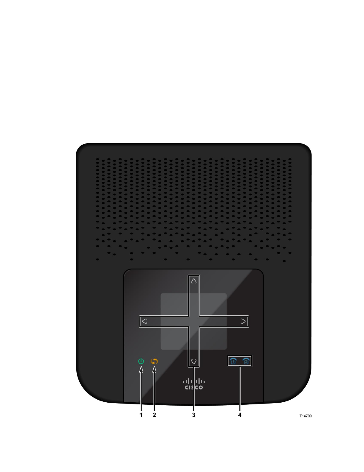
What's on the Top Panel?
The top panel of your Home gateway provides an LCD screen for easy setup and
configuration. Use the touch-sensitive arrow keys to navigate through the menu
options. Refer to Configuration and Operation of the the TES301 (see "Configuration
and Operation of the TES301" on page 19) for more information on this feature. The
top panel also provides LED status icons that indicate the operational state of your
gateway. Refer to the following diagram for a description of the top panel.
Page 26

Chapter 1 Introducing the TES301 IP Managed Services Home Gateway
6 4038767 Rev A
1 Power (Green/Red)—The Power LED lights up when the Home gateway is
powered on.The LED becomes red during a malfunction.
2 WPS Touch-Sensitive Key (Amber)—Touch for 3 seconds to initiate pairing
with Wi-Fi devices.
3 LCD with Touch-Sensitive Keys—LCD screen lights up by the wave of a hand
to display menu options for common setup and configuration functions. The
touch-sensitive keys, indicated by the up, down, left, and right arrows, help you
navigate through the menus.
4 Phone 1-2 (Blue)—The LED lights up blue when it is registered with the SIP
server. It flashes to indicate voice mail messages have been received.
Page 27
What's on the Back Panel?
4038767 Rev A 7
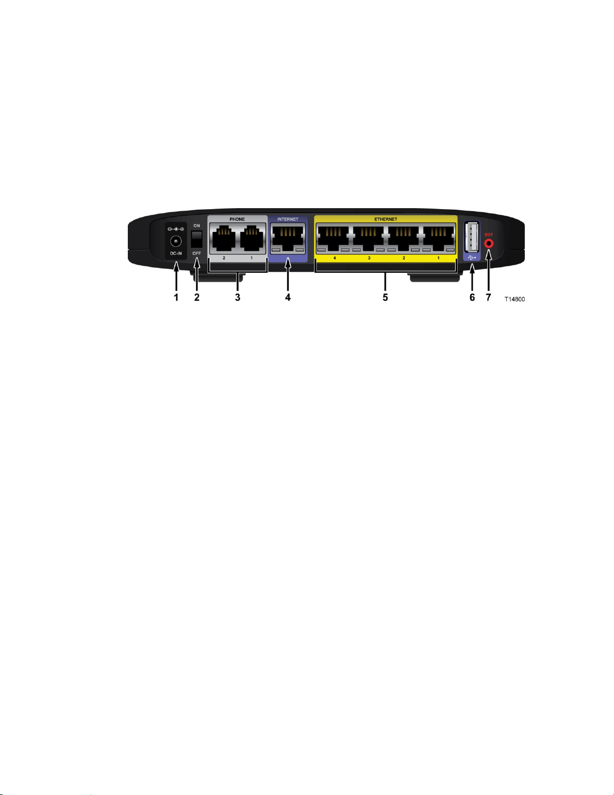
What's on the Back Panel?
The back panel of your Home gateway provides ports, power, and reset
mechanisms. Refer to the following diagram for a description of the back panel.
Note: This illustration may vary from the actual product.
1 Power—The Power port is where you will connect the power adapter that is
included in the box.
2 Power Switch—Use this switch to power on or off the device.
3 Phone 1-2—The Phone ports connect standard analog telephones to the device.
4 Internet—The Internet port connects to the Ethernet port on the DSL, fiber, or
cable modem.
5 Ethernet LAN 1-4—These Ethernet ports (1, 2, 3, 4) connect your gateway to
computers and other Ethernet network devices.
6 USB—The USB port connects to a USB storage device, such as a USB hard drive
or flash disk.
7 Reset—The Reset button restores the device to its original factory settings by
pressing and holding down the Reset button for 5 seconds.
Note: The reset button will restore the voice settings to the factory defaults,
which is to erase all SIP configurations
Page 28

Chapter 1 Introducing the TES301 IP Managed Services Home Gateway
8 4038767 Rev A
What's on the Side Panel?
The side panel of your Home gateway provides an additional USB port. Refer to the
following diagram for a description of the back panel.
USB—The USB port connects to a USB storage device, such as a USB hard drive or
flash disk.
Page 29

What's on the Bottom Panel
4038767 Rev A 9
What's on the Bottom Panel
The bottom panel of your Home gateway provides holes for mounting screws for
wall mounting and protective feet for vertical or wall mounting surfaces. The factory
label on the bottom panel provides serial number and MAC Address information.
Page 30

Page 31

4038767 Rev A 11
Introduction
This chapter provides instructions for installing the home gateway.
2 Chapter 2
Installing the Home Gateway
In This Chapter
Mounting the Home Gateway ............................................................ 12
Connecting the Home Gateway .......................................................... 15
Page 32

Chapter 2 Installing the Home Gateway
12 4038767 Rev A
Mounting the Home Gateway
Mounting the TES301 Horizontally
The Home gateway has four rubber feet on its bottom panel. Place the Home
gateway on a level surface near an electrical outlet.
Mounting the TES301 Vertically
The Home gateway has two wall-mount slots on its bottom panel. The distance
between the two slots is 4 inches (101.6 mm).
Two screws are needed to mount the Home gateway.
Page 33

Mounting the Home Gateway
4038767 Rev A 13
The following illustration shows the location and dimensions of the wall-mounting
slots on the bottom of the Home gateway. Use the information on this page as a
guide for mounting your Home gateway to the wall.
Note:
Mounting hardware illustrations are not true to scale.
Cisco is not responsible for damages incurred by insecure wall-mounting
hardware.
Page 34

Chapter 2 Installing the Home Gateway
14 4038767 Rev A
Follow these instructions:
1 Determine where you want to mount the Home gateway. Make sure that the
wall you use is smooth, flat, dry, and sturdy. Also make sure the location is
within reach of an electrical outlet.
2 Drill two holes into the wall. Make sure the holes are 4 inches (101.6 mm) apart.
3 Insert a screw into each hole and leave 2 mm (0.8 inches) below the head
exposed.
4 Maneuver the Home gateway so two of the wall-mount slots line up with the
two screws.
5 Place the wall-mount slots over the screws and slide the Home gateway down
until the screws fit snugly into the wall-mount slots.
Page 35
Connecting the Home Gateway
4038767 Rev A 15
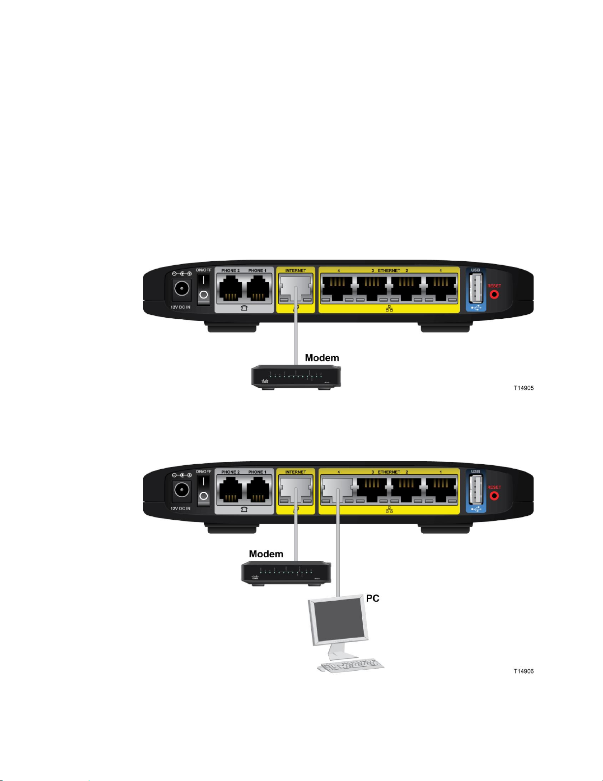
Connecting the Home Gateway
Perform the following steps to connect the TES301.
1 Make sure the power switch is in the Off position. Power down all devices that
you will connect to the gateway.
2 Insert a standard RJ-45 Ethernet cable (included) into the INTERNET port on the
gateway and connect the other end to your broadband network termination
device, such as a modem, router, GPON, or similar device.
Note: The illustrations in this guide show a modem connection as an example.
3 Insert a standard RJ-45 Ethernet cable into an Ethernet port on the gateway and
connect the other end to your PC.
Page 36

Chapter 2 Installing the Home Gateway
16 4038767 Rev A
4 Insert a standard RJ-11 telephone cable into the PHONE 1 port and connect the
other end to an analog telephone, cordless phone base station, or fax machine.
Note: To prevent an invalid connection to the circuit switched Telco network, do
not connect an RJ-11 telephone cable from the PHONE 1 (or PHONE 2) port on
the TES301 to the wall jack.
5 (Optional) You can connect the PHONE 2 port to a second analog telephone or a
fax machine.
6 (Optional) Connect additional PCs, or other Ethernet devices, such as an IP set-
top, to an ETHERNET port using a standard RJ-45 Ethernet cable.
Page 37

Connecting the Home Gateway
4038767 Rev A 17
7 Connect the included power adapter to the TES301 power port, and then plug
the power adapter into an electrical outlet.
Note: The power adapter that shipped with your device may differ from the
illustration below.
8 Use the power switch on the back panel to power on the TES301. The power LED
on the front panel will light up as soon as the device powers on. The LCD will
light up with a message that the device is booting up.
9 Once the device boots up, use the LCD menu to view the Internet status to verify
that the gateway is connected to the Internet as follows:
a Wave your hand over the LCD.
b Tap the up or down arrows repeatedly until the Internet Status icon is
highlighted.
Page 38

Chapter 2 Installing the Home Gateway
18 4038767 Rev A
c Tap the right arrow. The Internet Status page appears.
10 Tap the left arrow to exit this view.
11 To verify that your phone connection is setup properly, verify that the blue LED
light on the top panel of the gateway is lit.
12 Follow the instructions in your owner’s manual for your computer or other
wireless device to activate the wireless connection.
Note: A wireless connection requires a wireless-enabled device with an
802.11b/g/n wireless network adapter installed.
Page 39

4038767 Rev A 19
Introduction
This chapter provides instructions to use the web-based utility to set
up connections and configure the TES301 features.
3 Chapter 3
Configuration and Operation
of the TES301
In This Chapter
Logging into the Home Gateway ....................................................... 20
Dashboard .............................................................................................. 21
Internet ................................................................................................... 22
VoIP Settings ......................................................................................... 28
Wi-Fi ....................................................................................................... 40
Home Address ...................................................................................... 44
Configure the DLNA Settings ............................................................. 45
Advanced Settings ................................................................................ 46
Page 40

Chapter 3 Configuration and Operation of the TES301
20 4038767 Rev A
Logging into the Home Gateway
Complete the following steps to access the web-based utility.
Note: If the Home gateway was supplied by your service provider, then it may
restrict access to the web-based utility. Contact your service provider for the login
information.
1 Launch the web browser on your computer.
2 Type 192.168.29.1 in the URL Address field. This value is the Home gateway's
default IP address.
3 Press Enter. A login screen appears.
4 Is this the first time you have opened the web-based utility?
If yes, type the User name and Password provided by your service provider.
If no, enter the user name and password you established previously.
5 Click OK to continue. The web-based utility opens.
Page 41
Dashboard
4038767 Rev A 21
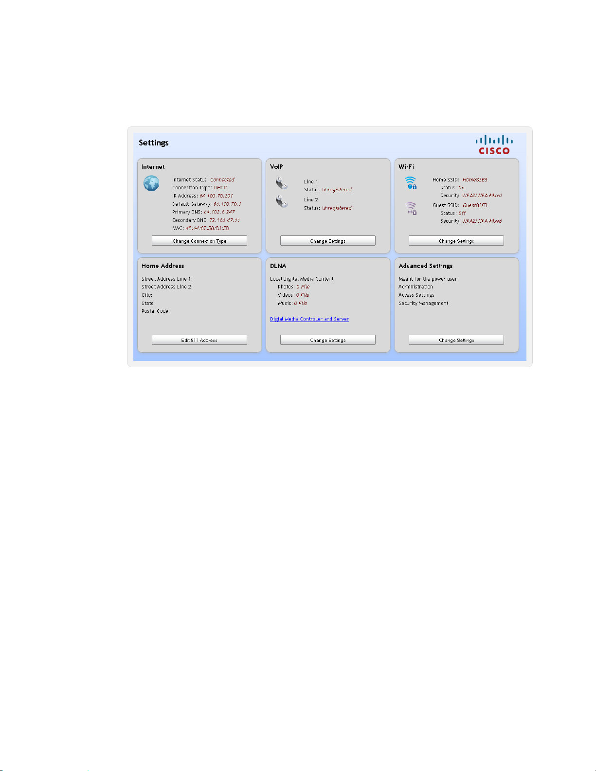
Dashboard
Page 42

Chapter 3 Configuration and Operation of the TES301
22 4038767 Rev A
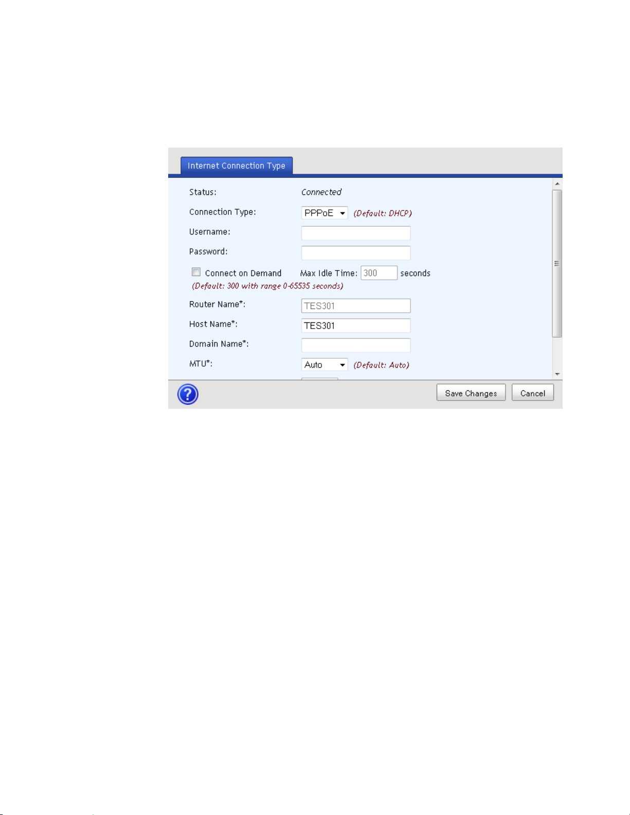
Internet
You will need to select a specific type of connection for your Internet connection.
Your selection will determine which additional parameters will be required to
complete your configuration.
Complete the following steps to set up your Internet connection.
1 From the TES301 dashboard, click the Change Connection Type button located
in the Internet cell.
2 Select one of the options from the Connection Type drop-down menu. The
screen refreshes to display the fields applicable to the connection type selected.
The list of options include the following:
DHCP (Default)
Static
PPPoE
PPTP
Page 43

Internet
4038767 Rev A 23
L2TP
3 Complete the following fields, which are applicable for all connection types:
Router Name—This field is not configurable.
Host Name—Enter the Host Name of your Internet server.
Domain Name—Enter the Domain Name of your local network.
MTU—Select Auto if you want the MTU size to be defined by the gateway.
Select Manual if you want to define the MTU size.
MTU Size—To edit this field, you need to select Manual for the MTU field.
The MTU Size value must be in the 1200 to 1500 range.
Page 44
Chapter 3 Configuration and Operation of the TES301
24 4038767 Rev A
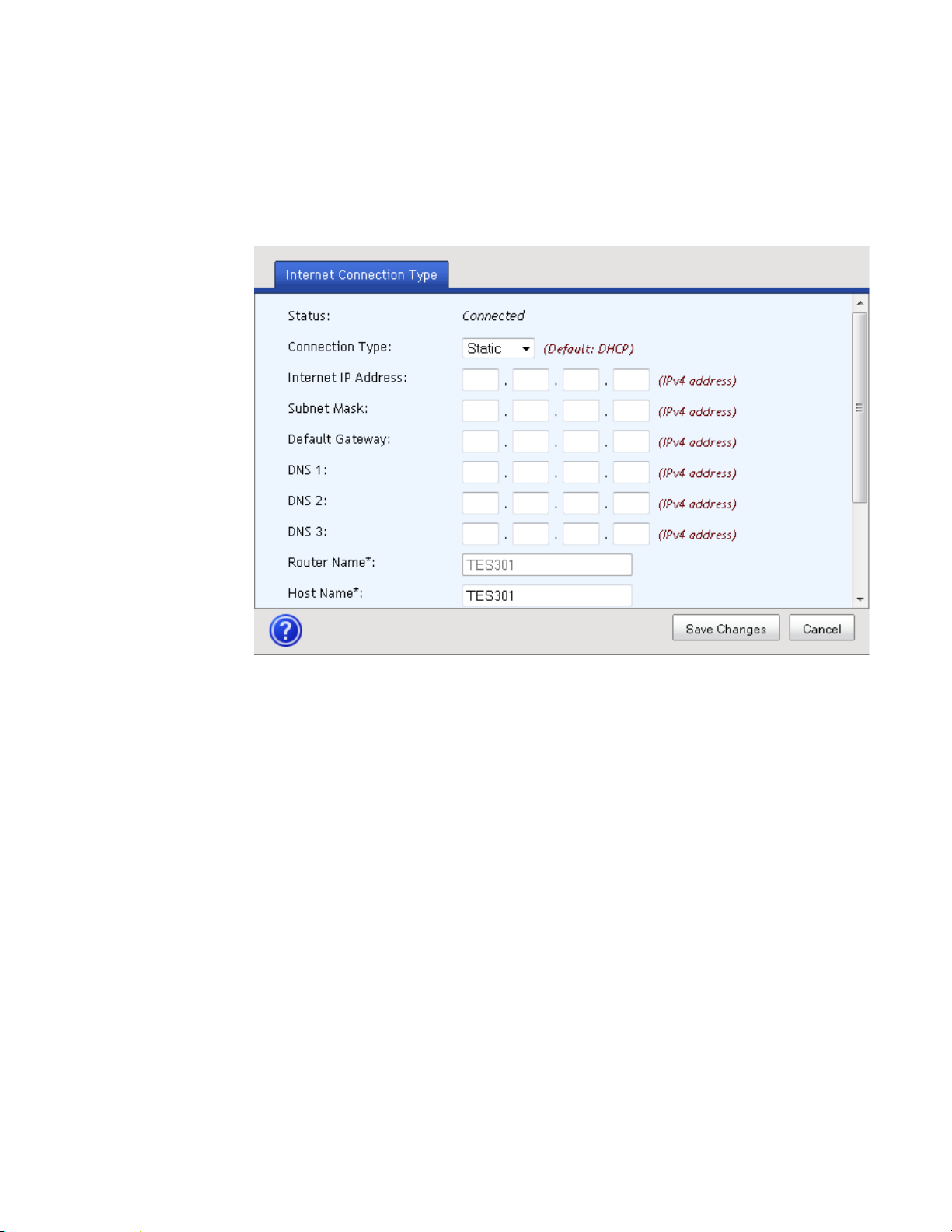
4 Complete the fields that are specific for the connection the type you selected in
step 2.
For a Static connection:
Note: Your service provider may provide static Internet IP address, subnet
mask, and default gateway values. Use the scroll bar to access all of the fields
on this screen.
– Internet IP Address—Enter the Gateway’s IP address as provided by
your service provider.
– Subnet Mask—Enter the Gateway’s Subnet Mask as provided by your
service provider.
– Default Gateway—Enter the IP address of the service provider’s server.
Page 45
Internet
4038767 Rev A 25
– DNS 1 through DNS 3—Enter the DNS (Domain Name System) server IP
address(es) provided by your service provider. At least one is required.
For a PPPoE connection:
Note: Use the scroll bar to access all of the fields on this screen.
– Username and Password—Enter the Username and Password as
provided by your service provider.
– Connect on Demand—You can configure the Router to cut the Internet
connection after it has been inactive for a specified period of time (Max
Idle Time). If your Internet connection has been terminated due to
inactivity, Connect on Demand enables the Router to automatically reestablish your connection as soon as you attempt to access the Internet
again.
Page 46

Chapter 3 Configuration and Operation of the TES301
26 4038767 Rev A
– Max Idle Time—Enter the number of minutes you want to have elapsed
before your Internet connection terminates. The default Max Idle Time is
5 minutes.
For a PPTP connection:
Note: Use the scroll bar to access all of the fields on this screen.
– Internet IP Address—Enter the Gateway’s IP address as provided by
your service provider.
– Subnet Mask—Enter the Gateway’s Subnet Mask as provided by your
service provider.
– Username and Password—Enter the Username and Password as
provided by your service provider.
– Connect on Demand—You can configure the Router to cut the Internet
connection after it has been inactive for a specified period of time (Max
Idle Time). If your Internet connection has been terminated due to
inactivity, Connect on Demand enables the Router to automatically reestablish your connection as soon as you attempt to access the Internet
again.
Page 47

Internet
4038767 Rev A 27
– Max Idle Time—Enter the number of minutes you want to have elapsed
before your Internet connection terminates. The default Max Idle Time is
5 minutes.
For an L2TP connection:
Note: Use the scroll bar to access all of the fields on this screen.
– Username and Password—Enter the Username and Password provided
by your service provider.
– L2TP Server IP—Enter the IP address of the L2TP server.
– Connect on Demand—You can configure the Router to cut the Internet
connection after it has been inactive for a specified period of time (Max
Idle Time). If your Internet connection has been terminated due to
inactivity, Connect on Demand enables the Router to automatically reestablish your connection as soon as you attempt to access the Internet
again.
– Max Idle Time—Enter the number of minutes you want to have elapsed
before your Internet connection terminates. The default Max Idle Time is
5 minutes.
5 Click Save Changes to save the information or Cancel to return to the
dashboard.
Page 48

Chapter 3 Configuration and Operation of the TES301
28 4038767 Rev A
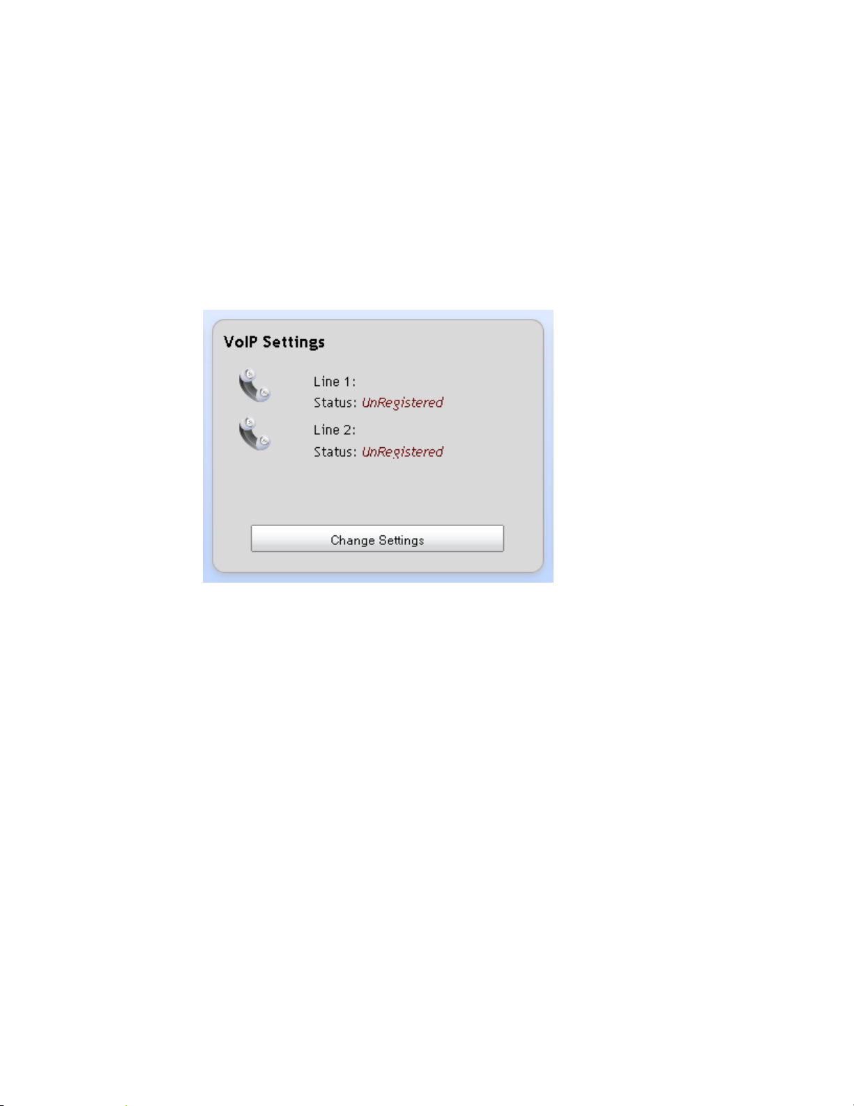
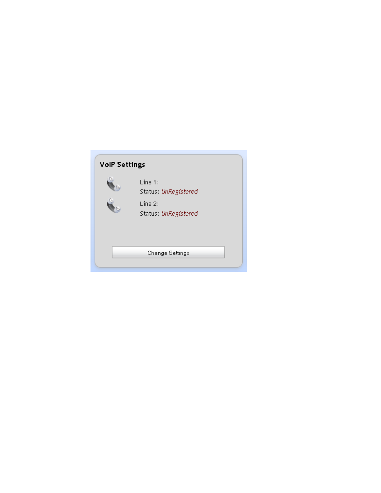
VoIP Settings
SIP
Before using voice service you must enter your subscriber account and session
initiation protocol (SIP) proxy server information that is obtained from your service
provider.
Complete the following steps to configure the SIP parameters for your VoIP settings.
1 From the TES301 dashboard, click the Change Settings button located in the
VoIP Settings cell.
Page 49

VoIP Settings
4038767 Rev A 29
2 From the SIP tab, complete the Subscriber Information fields.
Note: Use the scroll bar to access all of the fields on this screen.
Display Name—Enter a name that you want to appear in the display, such as
"Home," "Office," "David," "Mom."
User Name—Enter your SIP user ID that identifies you to the server. Each
VOIP / SIP account has a unique User Name.
Auth. ID—Enter a user name credential to identify your connection to the
server.
Auth. Password—Enter a password credential to authenticate your
connection to the server.
3 Complete the Proxy Server fields.
Note: Use the scroll bar to access all of the fields on this screen.
Proxy Server—Enter the host name or IP address of the SIP proxy server. All
SIP signaling traffic will be sent to the host server indicated by this
parameter.
Proxy Server Port—Enter the destination port to be used to connecting to the
SIP server.
Page 50

Chapter 3 Configuration and Operation of the TES301
30 4038767 Rev A
4 Complete the SIP Registrar Server fields.
Note: Use the scroll bar to access all of the fields on this screen.
Registrar Option—Select Disabled to ignore that the Registrar Server
feature. Select Enabled to activate this feature.
Registrar Server—If the Registrar Option is enabled, provide the host name
or IP address of the SIP registrar server.
Registrar Server Port—Enter the destination port to be used in connecting to
the SIP registrar server.
Registration Expires—Enter the number of seconds after which the
registration with the SIP server expires.
5 Complete the Outbound Proxy Server fields.
Note: Use the scroll bar to access all of the fields on this screen.
Outbound Server Option— Select Disabled to ignore the Outbound Server
feature.
Outbound Server—If the Outbound Server Option is enabled, provide the
host name or IP address of the outbound proxy server. If an Outbound
Server is specified, the device will send all SIP traffic (requests and
responses) to the host and port indicated.
Outbound Proxy Server port—Enter the destination port to be used to
connect to the outbound proxy.
Page 51

VoIP Settings
4038767 Rev A 31
Service
6 Complete the Local Settings fields.
Note: Use the scroll bar to access all of the fields on this screen.
SIP Local Port—Enter the port used for incoming and outgoing call control
signaling.
RTP Local Port—Enter the lowest value allowed for the port range to be used
for incoming and outgoing RTP streams.
7 Click Save Changes to save the information or Cancel to return to the
dashboard.
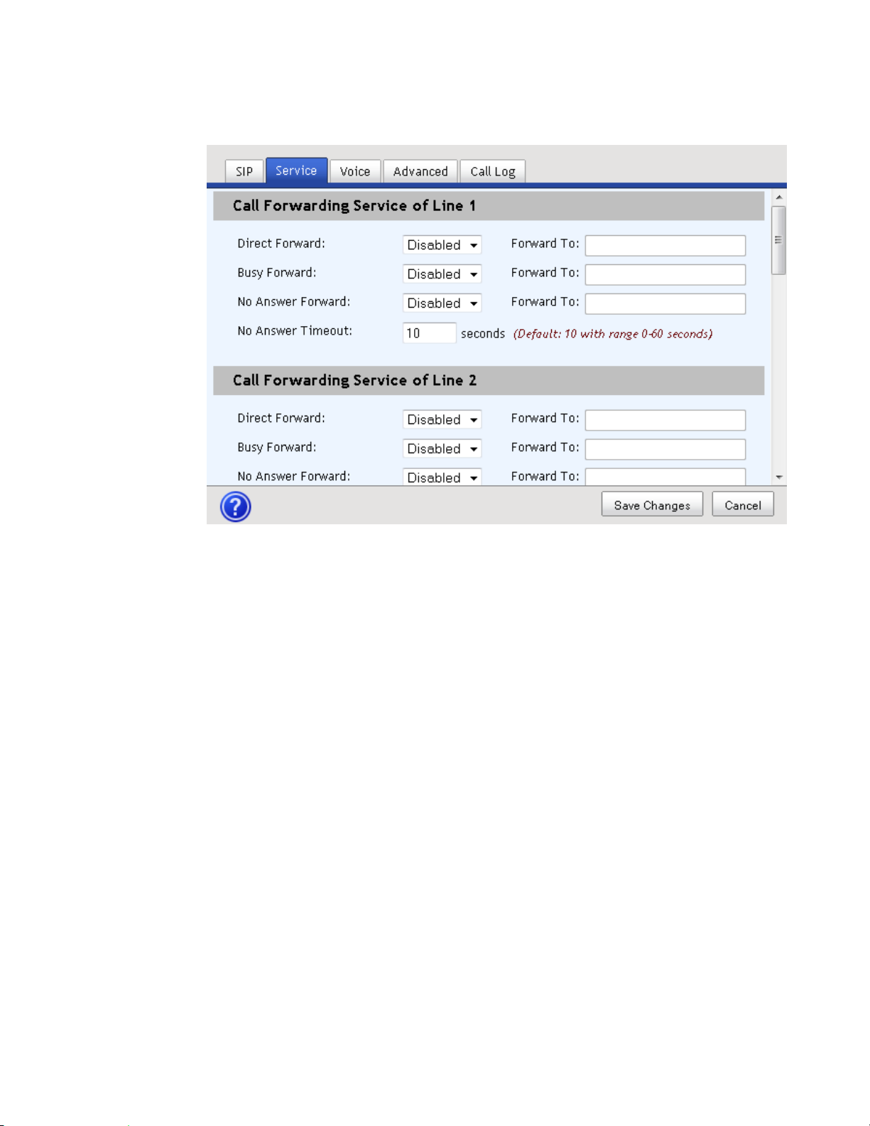
This tab allows you to configure call forward features for subscriber line 1 and 2
separately. Enter some commonly used numbers into speed dial entry list and enter
the numbers you don't want to be disturbed into call block entry list, those 2 entry
lists take effect on subscriber line 1 and 2 simultaneously.
Complete the following steps to configure the Service parameters for your VoIP
settings.
1 From the TES301 dashboard, click the Change Settings button located in the
VoIP Settings cell.
Page 52
Chapter 3 Configuration and Operation of the TES301
32 4038767 Rev A
2 Complete the fields for the Service tab.
Note: Use the scroll bar to access all of the fields on this screen.
Direct Forward—Select an option to enable or disable call forwarding. If you
select Enabled, enter the phone number to which you want to forward
incoming calls in the associated Forward To field.
Busy Forward—Select an option to enable or disable call forwarding-on-
busy. If you select Enabled, then use the associated enter the phone number
to which you want to forward incoming calls when this line is busy in the
associated Forward To field.
No Answer Forward—Select an option to enable or disable call forwarding-
on-no-answer. If you select Enabled, enter the phone number to which you
want to forward incoming calls in the associated Forward To field.
No Answer Timeout—Enter the number of seconds to wait before
forwarding a call using the forwarding-on-no-answer feature.
Speed Dial Entry 1 through 10—Enter up to 10 phone numbers that you
want in your speed dial directory. When you place a call for the number you
enter in Speed Dial Entry 1 field, simply press 0#. To call for the number for
Speed Dial Entry 2, press 1#; for entry 3 press 2#, and so forth.
Call Block Entry 1-10—Specify up to 10 phone numbers in this list from
which you wish to block all incoming calls.
3 Click Save Changes to save the information or Cancel to return to the
dashboard.
Page 53
VoIP Settings
4038767 Rev A 33
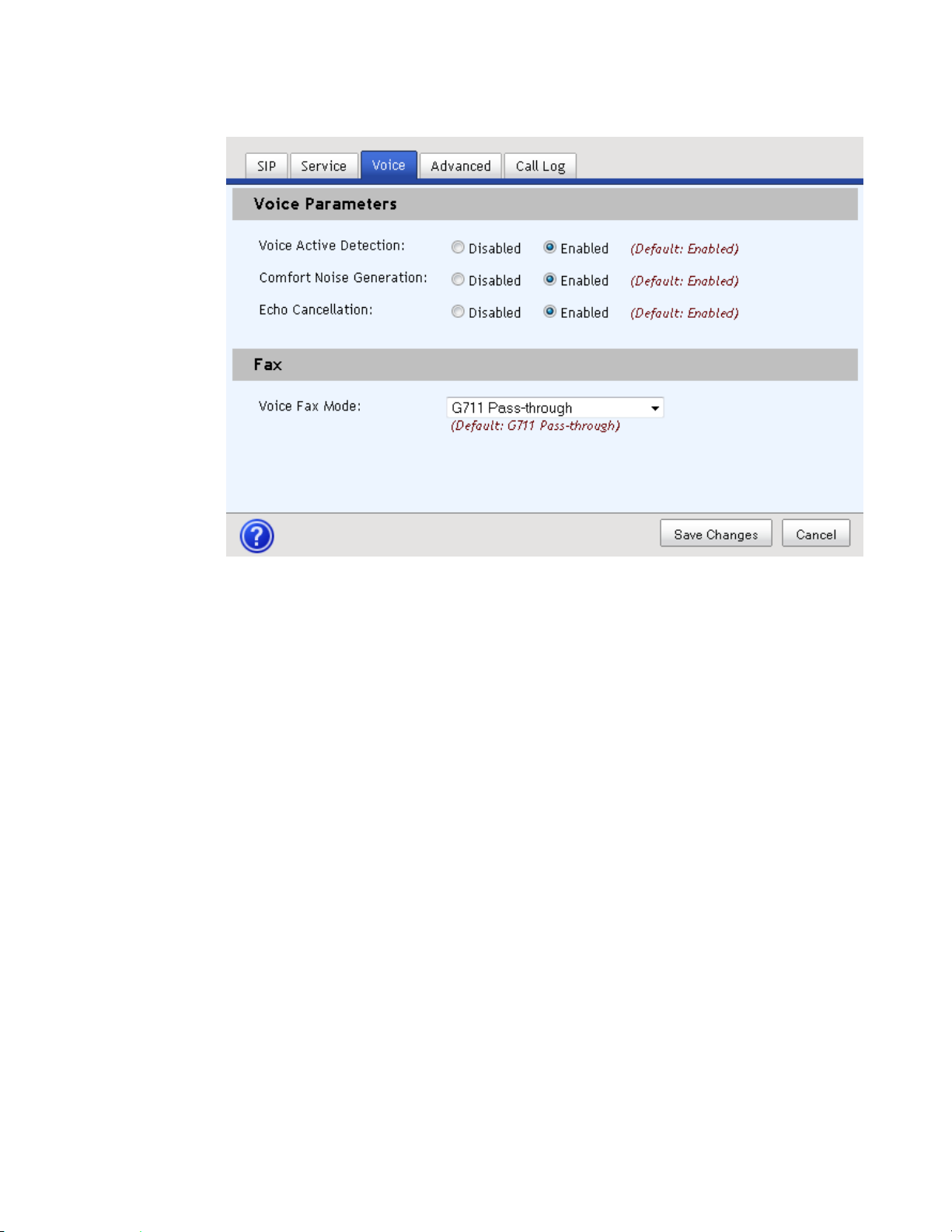
Voice
Voice Parameters listed on this tab can improve voice quality. If you want use FAX
service, you need to select the FAX mode that matches the remote FAX device.
Complete the following steps to configure the Voice parameters for your VoIP
settings.
1 From the TES301 dashboard, click the Change Settings button located in the
VoIP Settings cell.
Page 54
Chapter 3 Configuration and Operation of the TES301
34 4038767 Rev A
2 Complete the fields for the Voice tab.
Voice Active Detection—Voice activity detection (VAD) is a technique used
in speech processing in which the presence or absence of human speech is
detected. The main uses of VAD are in speech coding and speech recognition.
It can facilitate speech processing and can also be used to deactivate some
processes during a non-speech portion of an audio session. This technique is
used to avoid unnecessary coding and transmission of silence packets in
Voice over Internet Protocol applications, saving on computational resources
and network bandwidth.
Comfort Noise Generation—If enable this setting, CPE can automatically
generate artificial background noise to remote side when no speech during
voice call.
Echo Cancellation—Echo cancellation is used to describe the process of
removing echo from a voice communication in order to improve voice
quality.
Voice Fax Mode—You can select FAX relay mode to transmit FAX data
through IP network, None indicates CPE cannot send out FAX data but only
receive FAX data, G711 Pass-through indicates CPE send out FAX data with
G.711 codec, T.38 indicates CPE send out FAX data only support T.38
protocol, T.38 Fallback to Pass-through indicates CPE will try to use T.38, but
if transmission with T.38 failure, CPE automatically try to send out FAX data
with G.711 codec.
3 Click Save Changes to save the information or Cancel to return to the
dashboard.
Page 55
VoIP Settings
4038767 Rev A 35
Advanced
If the TES301 is behind a firewall, you can select NAT Traversal mode and enter the
necessary information obtained from your service provider, this function may help
traverse firewall and provide voice service normally. The Codec Settings fields allow
you to change the setting used in a voice call. Dual-tone multi-frequency signaling
(DTMF) Settings provide a method to transmit digital keys pressed during voice
calls.
1 From the TES301 dashboard, click the Change Settings button located in the
VoIP Settings cell.
2 Do you want to use the NAT Traversal Mode feature?
If no, select None from the NAT Traversal Mode drop-down menu; then,
skip to the last step.
Page 56

Chapter 3 Configuration and Operation of the TES301
36 4038767 Rev A
If yes, choose STUN or Port Mapping from the NAT Traversal Mode drop-
down menu; then, continue with the next step.
Note: Use the scroll bar to access all of the fields on this screen.
3 If you selected the STUN option, complete the following steps:
a STUN Server Address—Enter the address of a STUN server running on
public network. Your device will send a discover request to the STUN server
and decide NAT mode based on the response message from the STUN
server.
b STUN Server Port—Specify the port for the STUN server. Your device will
send a discover request to the STUN server via the specified port.
c NAT Keep Alive Interval—Enter the number of seconds to indicate the
interval for your device to send discover requests to keep NAT traversal
active.
d Skip to step 5 to continue.
4 If you selected the Port Mapping option, complete the following steps:
a External Router Address—Enter the external router address.
b External SIP Signal Port—Enter the external SIP signal port used to
communicate with SIP agent in public network.
c External Base RTP Port—Enter the external RTP stream port used to
communicate with SIP agent in public network.
5 Complete the following steps to configure Codec Settings:
a From the Disabled Codec list, select a Codec you want to enable.
Page 57

VoIP Settings
4038767 Rev A 37
b Click the Move Right arrow to move the selected item to the Enabled Codec
list.
c Use the Up/Down buttons to prioritize the Enabled Codecs.
d Select the top Codec in the Enabled list. The Codec Properties fields become
active.
e Complete the Codec Properties fields associated with the Codec selected:
– Payload Type—This value is pre-populated with a default setting. The
field will not be configurable if the default value is a required setting for
the codec selected.
– Name—Provide a name to identify the codec type.
– Frame Size in ms—Select a setting to configure interval between sending
RTP packets out to the RTP stream.
– Bit Rate—Select the data transmission rate from the list of available
options.
f DTMF Relay Method—Select one of the following methods by which DTMF
digits will be passed during a voice call:
– In Band—Select In Band mode to use the voice band when a key is
pressed during a voice call.
– Out of Band—Select Out of Band mode to use an independent band
when a key is pressed during a voice call. If you select this option, the
RFC2833 Payload Type field will appear for your to enter a value to
configure the RFC 2833 payload decimal.
– SIP Info—Select SIP Info if you want a key press to be sent remotely
through SIP packets during a voice call.
6 Click Save Changes to save the information or Cancel to return to the
dashboard.
Page 58

Chapter 3 Configuration and Operation of the TES301
38 4038767 Rev A
Call Log
Complete the following steps to review the Call Log for your VoIP usage.
1 From the TES301 dashboard, click the Change Settings button located in the
VoIP Settings cell.
2 Click the Call Log tab to view the call history for each line.
Page 59

VoIP Settings
4038767 Rev A 39
3 If desired, click one of the following filter options:
All—Displays all outgoing, received, and missed calls in the order placed or
received.
Outgoing—Displays only outgoing calls.
Received—Displays only received calls incoming calls.
Missed—Displays only missed incoming calls.
4 Click Delete to clear items from the Call Log or Cancel to return to the
dashboard.
Page 60
Chapter 3 Configuration and Operation of the TES301
40 4038767 Rev A
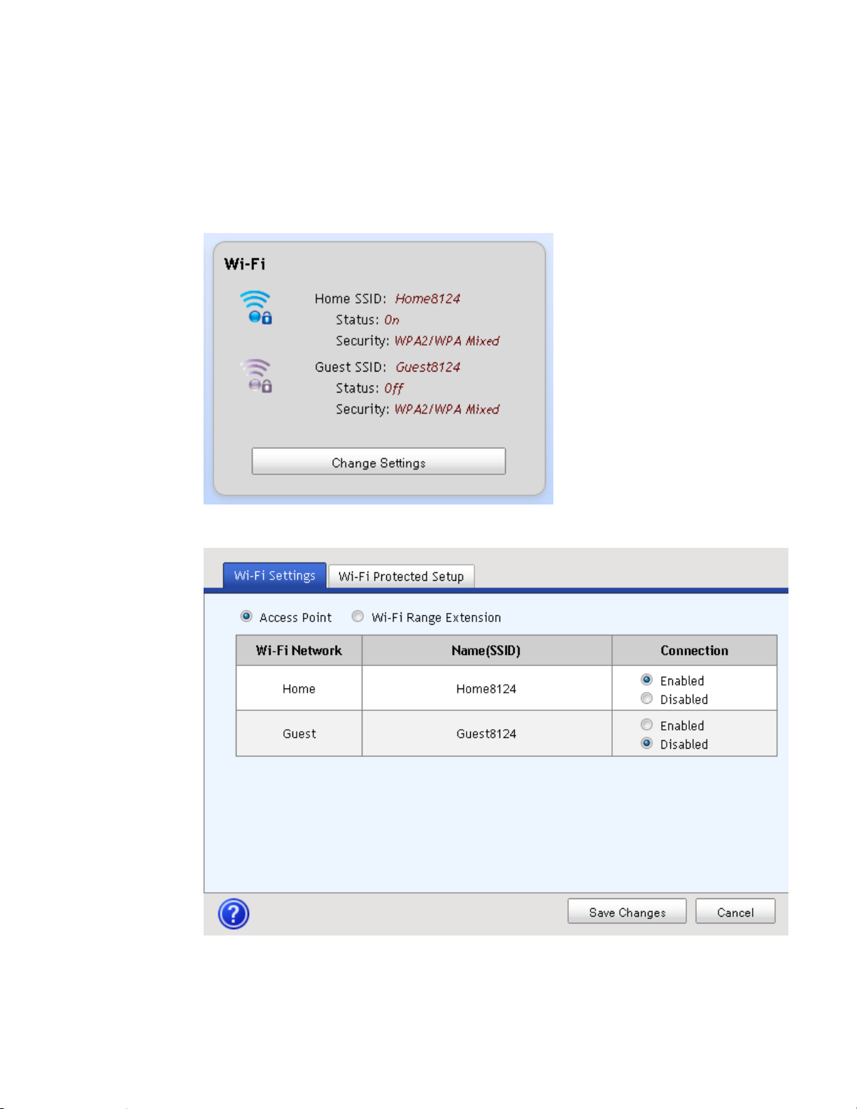
Wi-Fi
Complete the following steps to configure the Wi-Fi settings on your gateway.
1 From the TES301 dashboard, click the Change Settings button located in the
Wi-Fi cell.
2 Use the Wi-Fi Settings tab to indicate if this device is an Access Point device or
Wi-Fi Range Extension.
Page 61
Wi-Fi
4038767 Rev A 41
For an Access Point device, select the Access Point radio button; then,
indicate Enabled if you want the Wi-Fi Network enabled, or selected
Disabled to disable the Wi-Fi Network, for each SSID on your network. If
you are ready to pair devices, go to the Pair Devices (see "Connect Devices"
on page 41) section. Otherwise, skip to the last step.
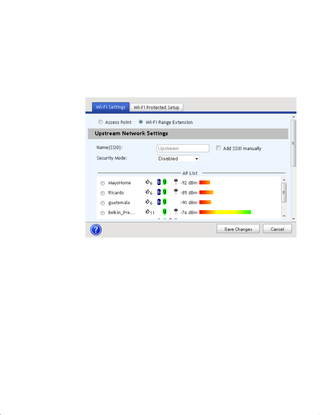
For repeater mode, select the Wi-Fi Range Extension radio button; then,
configure the fields on the page once it refreshes.
– Name (SSID)—This field is auto-populated with the name of the
associated Access Point. If you want to enter a different SSID, click the
Add SSID manually check box; then, enter the SSID you wish to
configure.
– Add SSID manually—Select this option to make the Name (SSID) field
configurable.
– Security Mode— Select the security mode of the associated Access Point,
Disabled, WPA, or WPA2. If you select WPA or WPA2, the Passphrase
field appears.
– Passphrase—Enter the passphrase of the associated Access Point.
3 Click Save Changes to save the information or Cancel to return to the
dashboard.
Page 62

Chapter 3 Configuration and Operation of the TES301
42 4038767 Rev A
Connect Devices
Complete the following steps to connect your gateway with a WPS-supported
device.
1 From the TES301 dashboard, click the Change Settings button located in the
Wi-Fi cell.
2 Click the Wi-Fi Protected Setup tab.
3 Select the network you want to associated with the wireless client device: Home
Network or Guest Network.
4 Use one of the following methods to pair devices.
Page 63

Wi-Fi
4038767 Rev A 43
If your client device has a Wi-Fi Protected Setup button, then:
– Click or press the Wi-Fi Protected Setup button on the client device.
– Click the Wi-Fi Protected Setup button on this screen.
– After the client device has been configured, click OK button. Then refer
back to your client device or its documentation for further instructions.
If your client device has a Wi-Fi Protected Setup PIN, then:
– Enter the PIN number in the field on this screen.
– Click Register button.
– After the client device has been configured, click OK button. Then refer
back to your client device or its documentation for further instructions.
If your client device requests the Router's PIN, enter the PIN number listed
on this screen. (It is also listed on the label on the bottom of the Router).
5 After the client device has been configured, click OK button. The Wi-Fi Protected
Setup Status, Network Name (SSID), Security, Encryption, and Passphrase are
displayed at the bottom of the screen.
6 Refer to your client device or its documentation for further instructions.
Page 64

Chapter 3 Configuration and Operation of the TES301
44 4038767 Rev A
Home Address
Complete the following steps to set up your 911 information.
1 From the TES301 dashboard, click the Edit 911 Address button located in the
Home Address cell.
2 Complete the fields on the screen.
Note: The fields may vary based on your geographic location.
3 Click Save Changes to save the information or Cancel to return to the
dashboard.
Page 65

Configure the DLNA Settings
4038767 Rev A 45
Configure the DLNA Settings
Complete the following steps to configure the DLNA settings on your gateway.
1 From the TES301 dashboard, click the Change Settings button located in the
DLNA cell.
2 Do you want to allow digital media sharing?
If yes, select the Enabled radio button under Sharing Permissions.
If no, select Disabled.
3 Click Save Changes to save the information or Cancel to return to the
dashboard.
Page 66
Chapter 3 Configuration and Operation of the TES301
46 4038767 Rev A
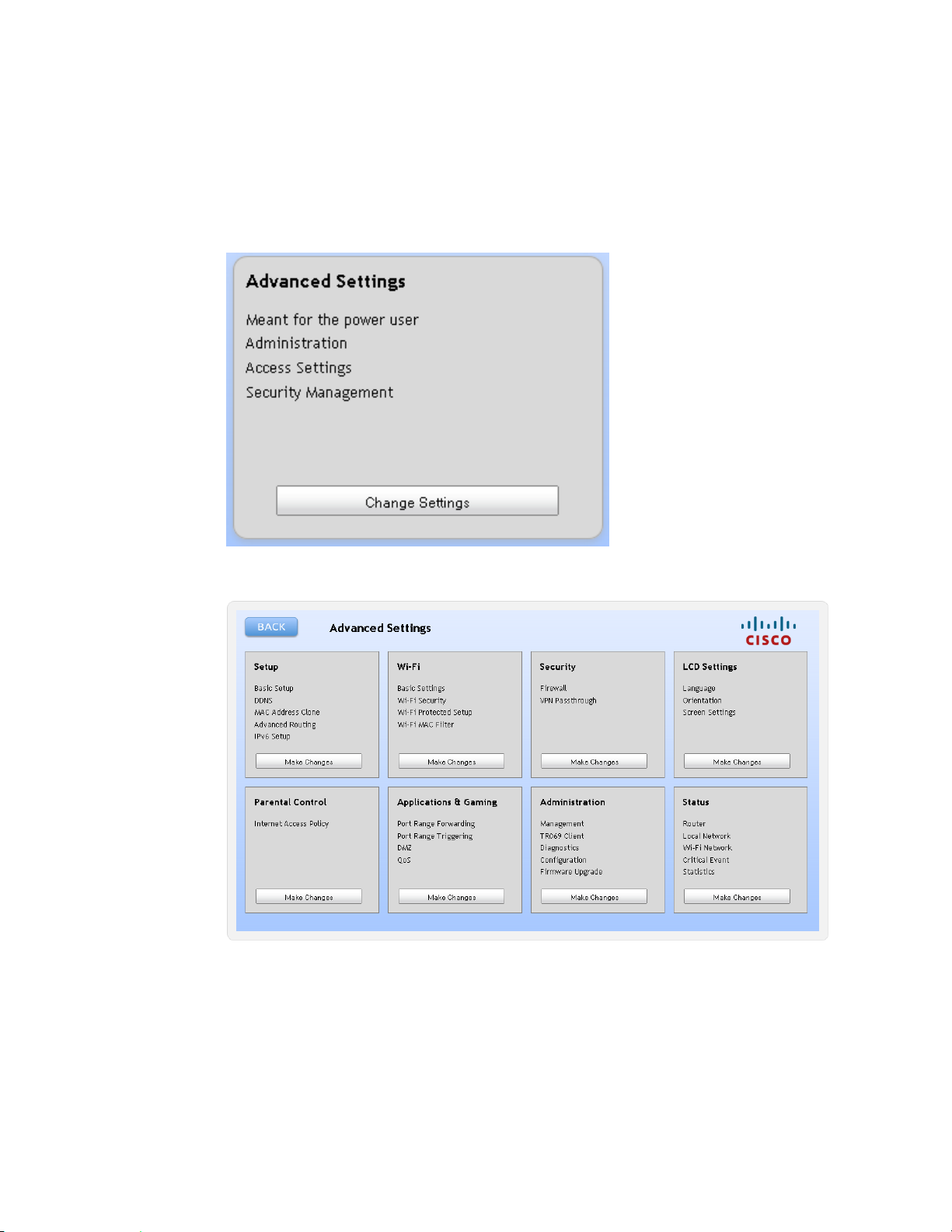
Advanced Settings
Complete the following steps to configure the advanced settings on your gateway.
1 From the TES301 dashboard, click the Change Settings button located in the
Advanced Settings cell.
2 Select Proceed from the confirmation pop-up message box. The Advanced
Settings dashboard appears.
Page 67

4038767 Rev A 47
Introduction
This chapter provides instructions to use the TES301 to view, play, and
share digital media. The TES301 can control up to four digital media
recording (DMR) devices simultaneously. You can browse digital
content by album, artist, date, genre, and other meta-data categories.
The rich media experience (RME) supports album art and thumbnails
for pictures and videos. With DLNA upload capability, you can
upload music, pictures, and video from devices such as mobile phone
directly to the TES301's Digital Media Server (DMS).
4 Chapter 4
Managing Digital Media
In This Chapter
Using the Media Controller ................................................................. 48
Using the Media Server ........................................................................ 51
Page 68

Chapter 4 Managing Digital Media
48 4038767 Rev A
Using the Media Controller
Complete the following steps to use the Digital Media Controller on your gateway.
1 From the TES301 dashboard, click the Digital Media Controller and Server
hyperlink located in the DLNA cell.
Page 69

Using the Media Controller
4038767 Rev A 49
A new window opens with the Digital Media Controller view displayed.
Note: Media content sources that are found in the home network (via USB or
connected network device) will appear in the Digital Media Server List.
Connected DMR devices will appear in the Digital Media Renderer List.
2 From the Digital Media Server List cell, select the source for the file(s) you want
to view or play. The DMS Media Content cell displays browser options for you
to navigate to the file(s).
3 From the DMS Media Content cell, select the file(s) you want to add view or
play; then, click the Add to Playlist icon (indicated by the plus symbol). The file
appears in the Playlist cell. You can remove a file from the playlist by clicking the
Remove from Playlist icon (indicated by the minus symbol).
Page 70

Chapter 4 Managing Digital Media
50 4038767 Rev A
4 When you have finished building your playlist, select the DMR device you want
to use and click the Play icon. The DMR will display the slideshows, play videos,
or play songs from the playlist.
Page 71

Using the Media Server
4038767 Rev A 51
Using the Media Server
Complete the following steps to upload files to the Digital Media Server on your
gateway.
1 From the TES301 dashboard, click the Digital Media Controller and Server link
located in the DLNA cell.
A new window opens with the Digital Media Controller view displayed.
Page 72
Chapter 4 Managing Digital Media
52 4038767 Rev A
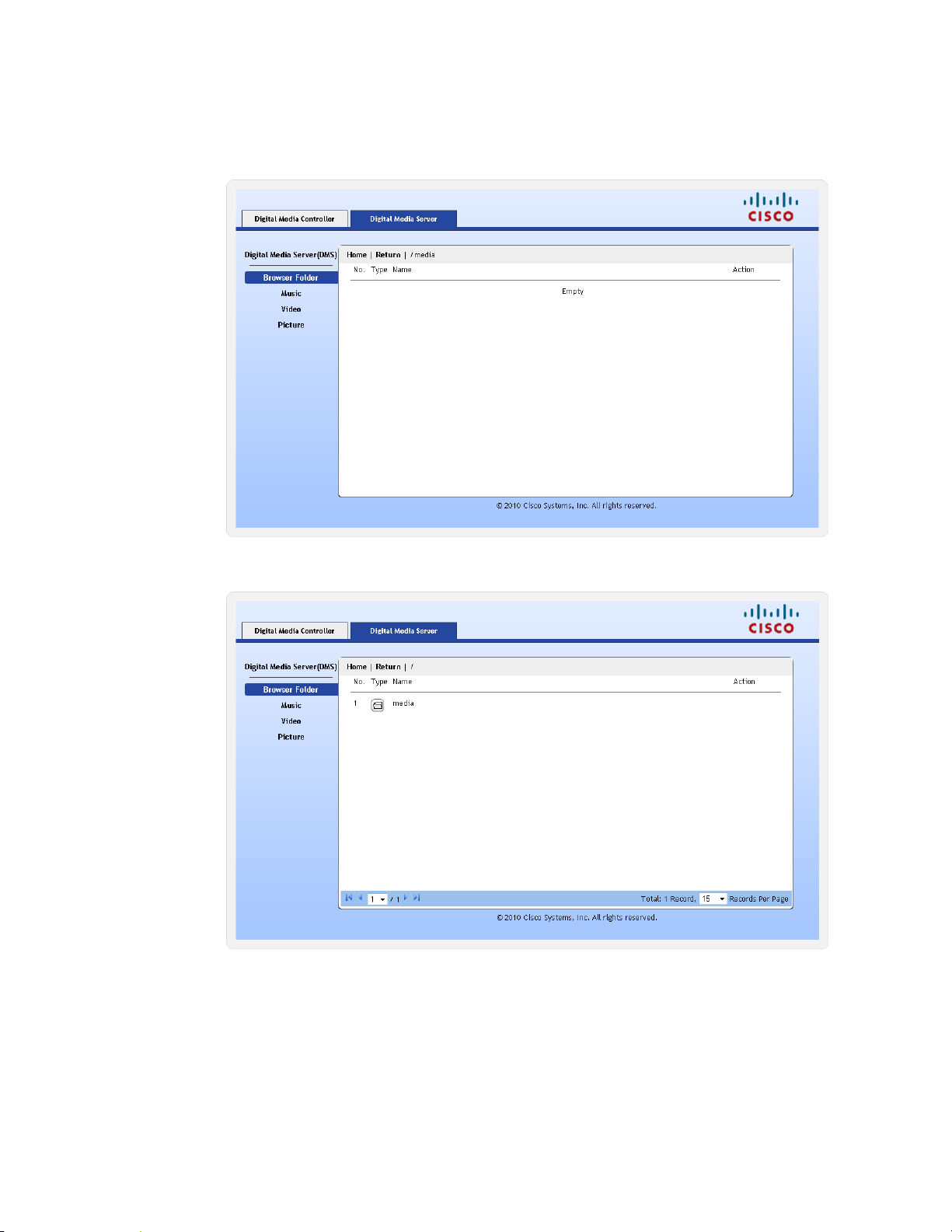
2 Click the Digital Media Server tab. The Digital Media Server view appears.
Note: Media content that is found in the home network (via USB or connected
network device) will appear in the window.
3 Click one of the category options to navigate to the media you want to play or
view (Browse Folder, Music, Video, or Picture).
Page 73

Using the Media Server
4038767 Rev A 53
4 Use the browser to navigate to the file(s) you want to play or view.
5. Select a file and click the Play icon in the Action column. The player associated
with that file type launches plays/displayes the file selected.
Page 74

Page 75

4038767 Rev A 55
Introduction
The top panel of the TES301 provides quick access to status and setup
options using the liquid crystal display (LCD). Read this chapter to get
familiar with the LCD and touch-sensitive navigation.
5 Chapter 5
Using the LCD
In This Chapter
Get Familiar with the LCD Menus and Pages .................................. 56
Internet ................................................................................................... 57
Phone ...................................................................................................... 58
Wi-Fi ....................................................................................................... 60
Connection ............................................................................................. 65
Settings ................................................................................................... 66
App Store ............................................................................................... 77
Page 76
Chapter 5 Using the LCD
56 4038767 Rev A
Get Familiar with the LCD Menus and Pages
Follow the steps below to navigate to the Home Page and through the menus, setup
and status pages available from the LCD.
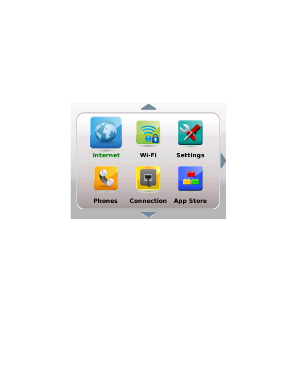
1 Wave your hand over the LCD. The Home page and the touch-sensitive arrow
keys appear. One icon will appear slightly larger than the others to indicate it is
the selected icon.
2 Tap the arrow keys to navigate to the view you want to use:
Up or down arrows navigate through the icons on the home page and
through the menu options and fields on the setup and status pages
The right arrow navigates to the menus, setup, and status pages for the
selected icon
The left arrow navigates from menus, setup, and status pages.
3 Tap each of the arrows to get familiar with the LCD navigation.
4 Tap the left arrow, repeatedly if necessary, to return to the Home page.
Page 77

Internet
4038767 Rev A 57
Internet
Follow the steps below to navigate to the Internet Status page.
1 Wave your hand over the LCD.
2 If necessary, tap the left arrow to navigate to the Home page.
3 Tap the up or down arrows to select the Internet icon.
4 Tap the right arrow. The Internet Status page appears.
5 Tap the left arrow to exit this view.
Page 78

Chapter 5 Using the LCD
58 4038767 Rev A
Phone
Follow the steps below to navigate to the Phone menus and options.
1 Wave your hand over the LCD.
2 If necessary, tap the left arrow to navigate to the Home page.
3 Tap the up or down arrows to select the Phone icon.
4 Tap the right arrow. The Phone status page appears.
5 Tap the right arrow to display the Call Log menu options.
Page 79

Phone
4038767 Rev A 59
Note: The number of calls for each category is displayed in parentheses. The
categories are All, Received, Outgoing, and Missed.
6 Tap the down or up arrow to scroll through the menu and select the category
you want to view.
7 Tap the right arrow. The details for the first call in that category appears.
8 Tap the down and up arrows to page through the call details for each call in that
category.
9 Tap the left arrow to exit this view.
Page 80

Chapter 5 Using the LCD
60 4038767 Rev A
Wi-Fi
Follow the steps below to navigate to the Wi-Fi Status page.
1 Wave your hand over the LCD.
2 If necessary, tap the left arrow to navigate to the Home page.
3 Tap the up or down arrows to select the Wi-Fi icon.
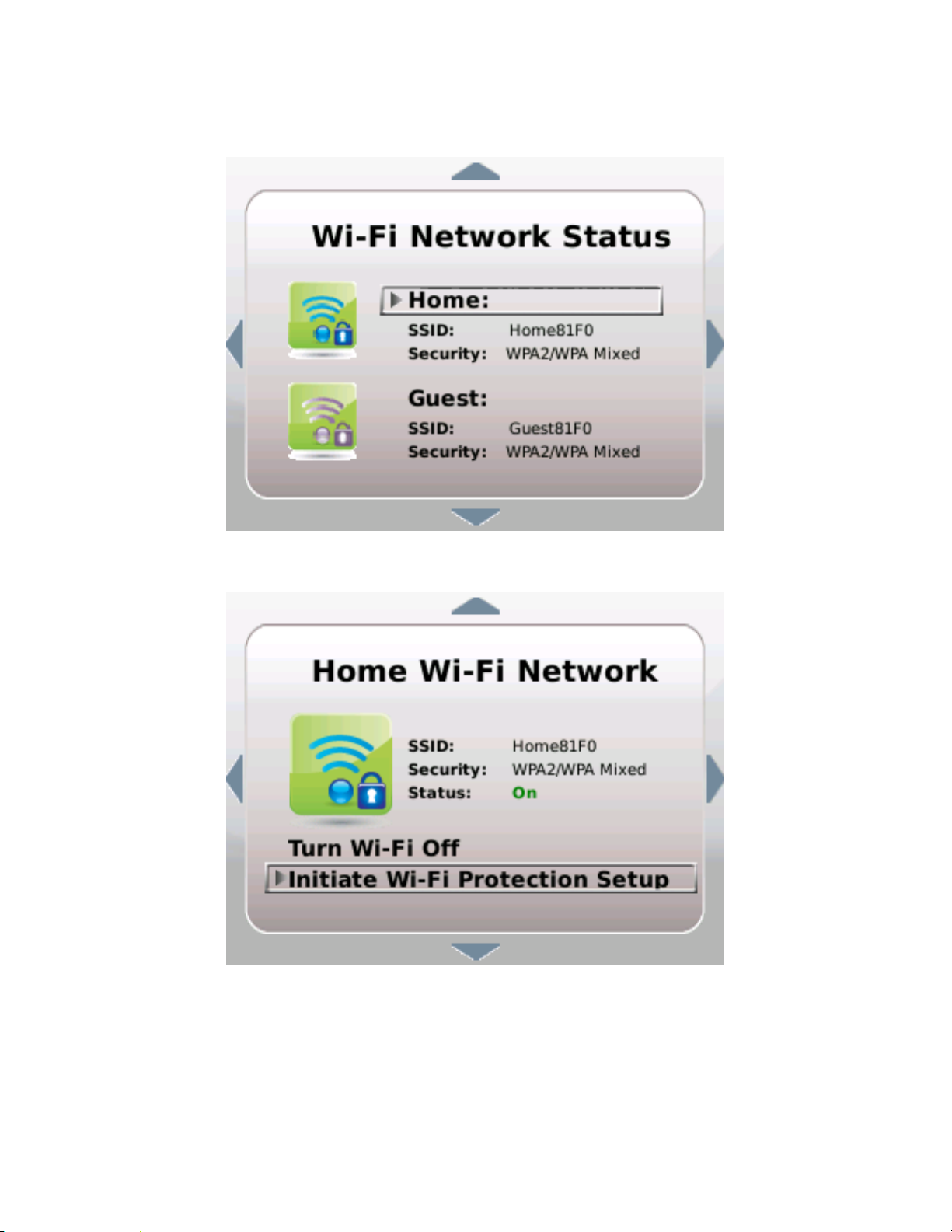
4 Tap the right arrow. The Wi-Fi Status page appears.
5 Tap the left arrow to exit this view.
Turn Wi-Fi Off or On
If necessary, refer to the previous section to access the Wi-Fi Network Status page;
then, follow the steps below to turn Wi-Fi off or on.
1 From the Wi-Fi Network Status page, tap the down or up arrow keys to highlight
the SSID you wish to manage.
Page 81
Wi-Fi
4038767 Rev A 61
2 Tap the right arrow. Options for the selected SSID appear.
3 Tap the down or up arrow keys to select Turn Wi-Fi Off/On.
Page 82

Chapter 5 Using the LCD
62 4038767 Rev A
4 Tap the right arrow. A confirmation request appears.
5 Tap the right arrow again to accept the change or tap the left arrow to cancel the
request.
6 Tap the left arrow to exit the SSID details page.
Initiate Wi-Fi Protection Setup
Complete the following steps to initiate Wi-Fi Protection Setup.
Before you proceed:
At least one SSID must already be set up. Go to the Wi-Fi (on page 40) section to
setup an SSID.
Wi-Fi must be turned on for the SSID you are managing. Go to Turn Wi-Fi Off or
On (on page 60) if Wi-Fi is not already turned on.
1 From the Wi-Fi Network Status page, tap the down or up arrow keys to highlight
the SSID you wish to manage.
Page 83

Wi-Fi
4038767 Rev A 63
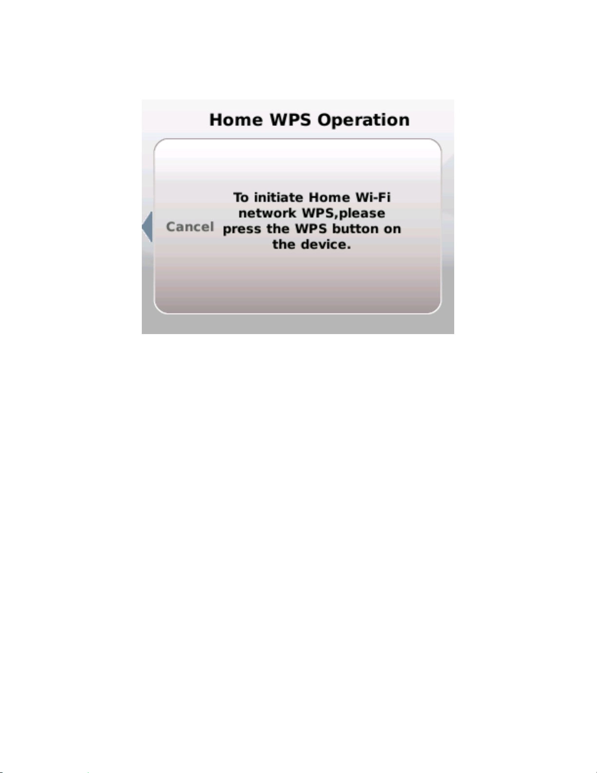
2 Tap the right arrow. Options for the selected SSID appear.
Tap the down or up arrow keys to select Initiate Wi-Fi Protection.
Page 84
Chapter 5 Using the LCD
64 4038767 Rev A
3 Tap the right arrow. Follow the instructions that appear or tap the left arrow to
cancel the request.
4 When initiation is complete, tap the left arrow to exit this view.
Page 85

Connection
4038767 Rev A 65
Connection
Follow the steps below to navigate to the Connection status page.
1 Wave your hand over the LCD.
2 If necessary, tap the left arrow to navigate to the Home page.
3 Tap the up or down arrows to select the Connection icon.
4 Tap the right arrow. The Connection status page appears.
5 Tap the left arrow to exit this view.
Page 86

Chapter 5 Using the LCD
66 4038767 Rev A
Settings
Follow the steps below to navigate to the Settings menus and options.
1 Wave your hand over the LCD.
2 If necessary, tap the left arrow to navigate to the Home page.
3 Tap the up or down arrows to select the Settings icon.
4 Tap the right arrow. The Settings menu appears.
Note: Tap the up or down arrow keys to scroll through the list of options.
5 Continue with the section for the menu option you wish to use.
Page 87

Settings
4038767 Rev A 67
Review Your Emergency 911 Address
Complete the following steps to review your Emergency 911 Address information.
1 From the Settings menu, tap the up or down arrows to select Emergency 911
Address.
2 Tap the right arrow to view the current Emergency 911 Address information.
Note: Go the following sections in chapter 3 to make changes to this
information:
Logging into the Home Gateway (on page 20)
Home Address (on page 44)
3 Tap the left arrow to exit this view.
Page 88

Chapter 5 Using the LCD
68 4038767 Rev A
Perform Factory Reset
Complete the following steps to perform a Factory Reset.
1 From the Settings menu, tap the up or down arrows to select Factory Reset.
2 Tap the right arrow. Instructions to perform a factory reset appear.
3 Follow the instructions that appear in the LCD screen or tap the left arrow to exit
without making changes.
Page 89

Settings
4038767 Rev A 69
Select Language Settings
Complete the following steps to select your preferred Language.
1 From the Settings menu, tap the up or down arrows to select Language.
2 Tap the right arrow to view the current language setting.
3 Tap the up or down arrow keys to select the language you prefer to appear in the
LCD screens and menus.
4 Tap the right arrow. A confirmation request appears.
5 Tap the right arrow again to accept the change or tap the left arrow to cancel the
request.
6 Tap the left arrow to exit the Language menu.
Page 90

Chapter 5 Using the LCD
70 4038767 Rev A
Select LCD Display Orientation
Complete the following steps to select your preferred LCD display orientation.
1 From the Settings menu, tap the up or down arrows to select LCD Display
Orientation.
2 Tap the right arrow to change the current setting. A confirmation request
appears.
3 Tap the right arrow again to accept the change or tap the left arrow to cancel the
request.
4 Tap the left arrow to return to the Settings menu.
View Network Information
Complete the following steps to view your network information.
1 From the Settings menu, tap the up or down arrows to select Network Info.
Page 91

Settings
4038767 Rev A 71
2 Tap the right arrow. The Network Information menu appears.
3 Tap the up or down arrows to select the menu option for the information you
want to review.
4 Tap the right arrow. The details for that menu option appears.
Note: The information in the example above is managed by your service
provider. Contact your service provider to request/Go to --- and follow the
instructions to make changes to this information.
5 Tap the left arrow to exit this view.
Page 92
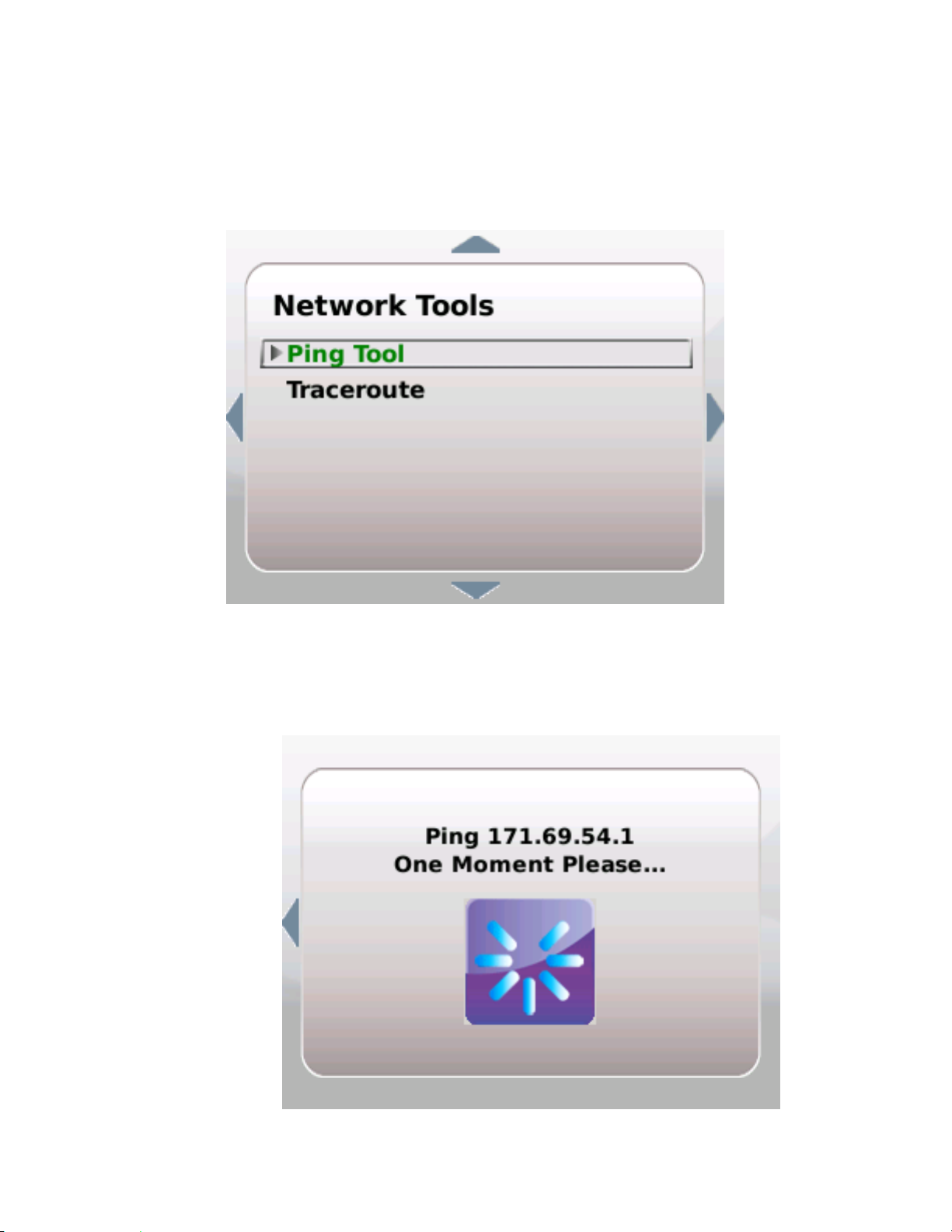
Chapter 5 Using the LCD
72 4038767 Rev A
Use Network Tools
Ping in Process
Complete the following steps to access and use the Network Tools options.
1 From the Settings menu, tap the up or down arrows to select Network Tools.
2 Tap the right arrow to view the Network Tools menu options.
3 Tap the up or down arrow keys to highlight the option you want to use:
Ping—Pings the IP address of the default gateway of the Internet WAN
connection. To use this option, highlight it and tap the right arrow. A
request-in-process message appears followed by a results page.
Page 93

Settings
4038767 Rev A 73
Ping Results
Reboot
Traceroute—To use this option, highlight it and tap the right arrow. A
request-in-process message appears followed by a results page.
1 Tap the left arrow to exit this view.
Complete the following steps to perform a Reboot.
1 From the Settings menu, tap the up or down arrows to select Reboot.
2 Tap the right arrow. Instructions to perform a reboot appear.
3 Follow the instructions that appear in the LCD screen or tap the left arrow to exit
without making changes.
Page 94
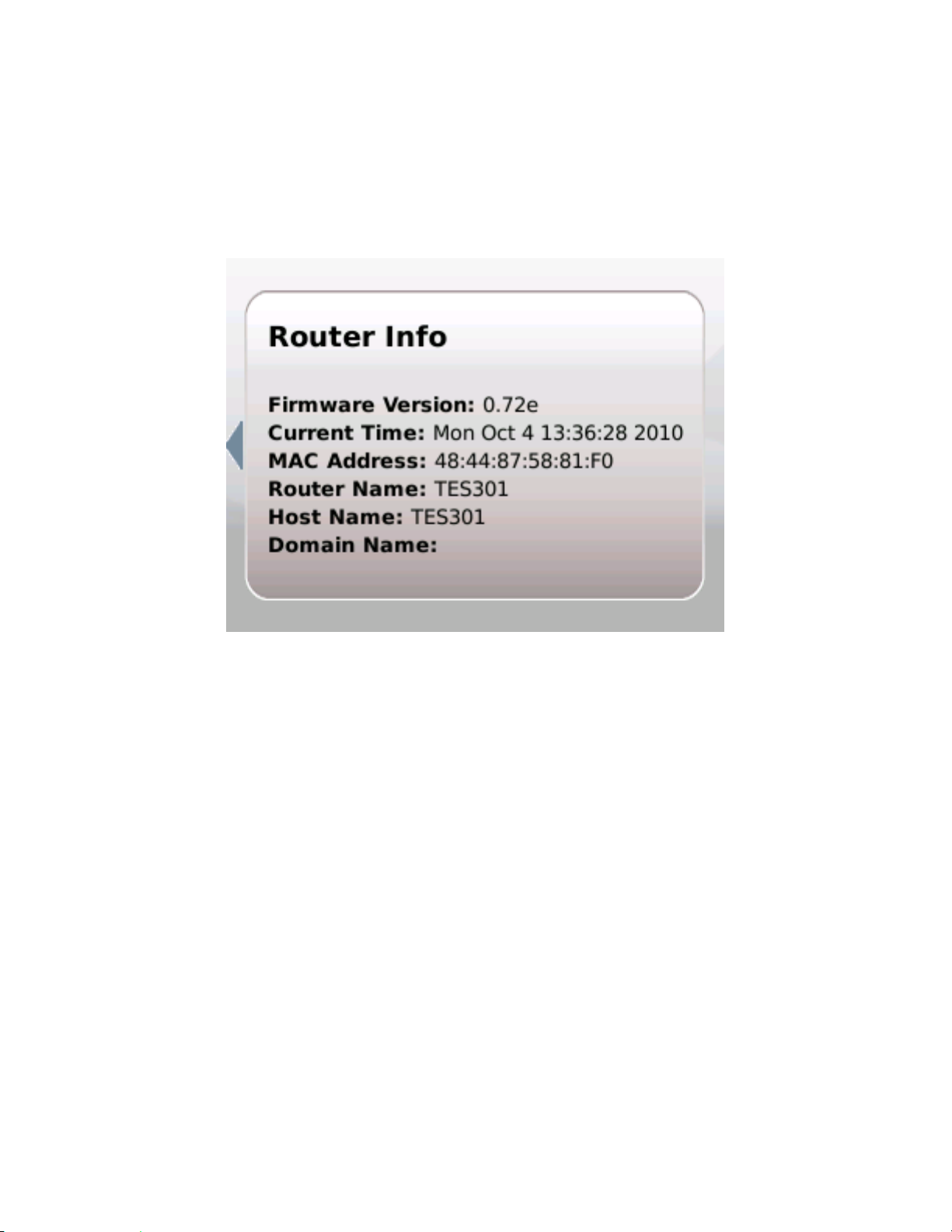
Chapter 5 Using the LCD
74 4038767 Rev A
View Router Information
Complete the following steps to view your router information.
1 From the Settings menu, tap the up or down arrows to select Router Info.
2 Tap the right arrow. The Router Information page appears.
Note: This information is managed by your service provider. Contact your
service provider to request/Go to --- and follow the instructions to make changes
to this information.
3 Tap the left arrow to exit this view.
Page 95

Settings
4038767 Rev A 75
View System Event Log
Complete the following steps to view the system event log.
1 From the Settings menu, tap the up or down arrows to select Sys Event Log.
2 Tap the right arrow. The System Event Log page appears.
3 Tap the left arrow to exit this view.
Set Up Time of Day Parameters
Complete the following steps to select your preferred Time Zone settings.
1 From the Settings menu, tap the up or down arrows to select Time (Manual
Configure).
Page 96

Chapter 5 Using the LCD
76 4038767 Rev A
2 Tap the right arrow to view the current time zone setting.
3 Tap the up or down arrows to highlight the time zone you prefer to use.
4 Tap the right arrow. A confirmation message appears.
5 (Optional) Tap the down arrow to change the Daylight Savings setting.
6 Tap the left arrow to exit this view.
Page 97

App Store
4038767 Rev A 77
App Store
Follow the steps below to navigate to the App Store menus and options.
1 Wave your hand over the LCD.
2 If necessary, tap the left arrow to navigate to the Home page.
3 Tap the Up/Down arrows to select the App Store icon.
4 Tap the right arrow. The App Store menu appears.
5 Highlight the application you want to manage (add, modify, or delete).
6 Click the right arrow and follow the on-screen instructions.
7 Tap the left arrow to exit.
Page 98

Cisco Systems, Inc.
5030 Sugarloaf Parkway, Box 465447
Lawrenceville, GA 30042
678 277-1120
800 722-2009
www.cisco.com
This document includes various trademarks of Cisco Systems, Inc. Please see the Notices
section of this document for a list of the Cisco Systems, Inc. trademarks used in this
document.
Product and service availability are subject to change without notice.
© 2011 Cisco and/or its affiliates. All rights reserved.
May 2011 Printed in USA
Part Number 4038767 Rev A
 Loading...