

Page 1

Cisco TelePresence
ISDN GW 3241
Getting Started Guide
61-0019-08
Page 2

2
Contents
General information ................................................................................................................ 3
About the Cisco TelePresence ISDN GW 3241 ................................................. 3
Package contents ........................................................................................................ 3
Port and LED location ................................................................................................ 3
LED behavior ................................................................................................................ 4
Connecting the ISDN GW 3241 ............................................................................................ 6
Before you start .......................................................................................................... 6
Your ISDN connection ............................................................................................... 6
Step one: Connect power ........................................................................................ 7
Step two: Connect to Ethernet Port A ................................................................. 7
Step three: Connect to the ISDN ports ................................................................ 7
Initial configuration ................................................................................................................. 8
Step one: Connect to the console port ............................................................... 8
Step two: Configure Ethernet Port A settings .................................................. 8
Step three: Assign an IP address to the ISDN GW 3241 (optional) ............9
Step four: Discover the IP address of the ISDN GW 3241 ...........................10
Configuring the ISDN GW 3241 .........................................................................................11
Step one: Log in to the web interface ...............................................................11
Step two: Set up the ISDN interface ...................................................................11
Step three: Configure the ISDN ports ................................................................11
Step four: Configure call control .........................................................................11
Step five: Configure the dial plan ........................................................................11
Troubleshooting and technical support information ...............................................13
Calls fail to complete ...............................................................................................13
Using the event log to help solve a problem ..................................................13
Getting more help ....................................................................................................13
Pin outs .......................................................................................................................................14
Disclaimers and notices ........................................................................................................15
Page 3
General information
3
General information
About the Cisco TelePresence ISDN GW 3241
The Cisco TelePresence ISDN GW 3241 (ISDN GW 3241) is a high performance
video gateway which enables ISDN network connectivity for Cisco TelePresence IPbased video infrastructure products as well as IP-based endpoints.
Package contents
The following items are included with the ISDN GW 3241. Verify that you have
these items before installing the device:
Cisco TelePresence ISDN GW 3241
Console cable (blue)
Power cable
Rack mounting kit
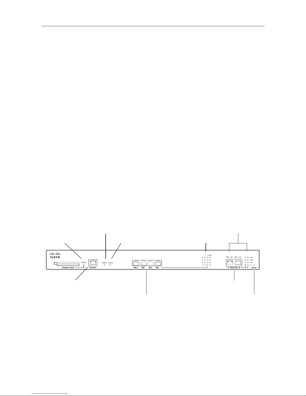
Port and LED location
Figure 1 shows the position of ports and LEDs on the ISDN GW 3241.
Figure 1: ISDN GW 3241 front panel
LL
2
3
4
Cisco ISDN GW 3241
ISDN Ports
Ethernet Ports
Status LED
Alarm LED
Compact Flash
ISDN Port Status LEDs
Power LED
Ethernet Port Status LEDs
Activity LED
Console Port
Page 4

General information
4
LED behavior
Table 1 describes the behavior of the LEDs.
Table 1: ISDN GW 3241 LED behavior
LED Color Indicates
Compact Flash
Activity
Flashing
green
One of:
The device is booting
A configuration change has been made
The configuration is being transferred by FTP
Status Green The device is operating normally
Alarm Red The device is booting or has developed a fault. For
example:
Temperature outside normal limits
Fan failure
Battery failure of the internal clock
See the web interface for more information about
the problem (go to
Status > Health)
ISDN Port Status, for each ISDN port:
L1 Off There is no connection on this port, or the device
is not receiving framing (also known as Red
Alarm)
Flashing
green
The device is receiving framing, but the far end is
not receiving framing (also known as Yellow
Alarm)
Green The port is connected to the far end
L2 Green Layer 2 connectivity has been achieved with the
ISDN network from this port. This means that
D-channel signaling has been established with the
network
Act Green At least one active call is using this port. Data is
currently being received on this port
Page 5

General information
5
Ethernet Port Status, for each Ethernet port:
FDX Green The link has been negotiated as a full-duplex link
Act Green Packets are being transmitted on this port
Link Green The speed of the link from this port, which is
either 10, 100, or 1000 Mbps
Power Blue The device is receiving power
Table 1: ISDN GW 3241 LED behavior (continued)
LED Color Indicates
Page 6

Connecting the ISDN GW 3241
6
Connecting the ISDN GW 3241
Before you start
Your ISDN connection
Outside North America
Check with your network provider to ensure that your incoming ISDN PRI line is
terminated in an NTU/CSU (Network Termination Unit/ Channel Service Unit). If
it is not, then seek their advice regarding the provisioning of such a device. Do not
connect the ISDN GW 3241 directly to an external ISDN line.
Within North America
If your network provider has not terminated all of your incoming ISDN PRI lines
with an NTU/CSU, we recommend that you install a suitably approved CSU to
protect the ISDN GW 3241 from damage by surges on your ISDN PRI lines.
IMPORTANT: Before installing the ISDN GW 3241, you must read the
safety information at http://www.cisco.com/go/telepresence/safety
To reduce the risk of fire, use only 26 AWG or larger telecommunication
line cord.
If you do not install a CSU between the incoming ISDN PRI lines and the
ISDN GW 3241, then the ISDN GW 3241 must be installed in a
restricted location as defined by EN, IEC and UL60950. This is defined as
an area intended for qualified or trained personal only with access
controlled by a locking mechanism such as a key.
If you do not install a CSU between the incoming ISDN PRI lines and the
ISDN GW 3241, then you are required to connect the ISDN GW 3241
to a protective earth as follows:
Connect a protective earth cable (not supplied) to the terminals on the
rear of the chassis marked with the earth symbol .
Connect the other end of this cable to a true earth.
The earth terminal accepts two M4 screws on a 16mm (5/8") spacing for
use with a two hole copper lug (such as the Panduit LCD10-10A-L).
!
Page 7

Connecting the ISDN GW 3241
7
Step one: Connect power
Connect the power connector on the rear of the device to the power supply using the
supplied power cable. (There is no On/Off switch.)
Step two: Connect to Ethernet Port A
Connect an Ethernet cable from Ethernet Port A to an Ethernet switch (rather than a
hub, to minimize interference from other devices on the network). The Ethernet
port is a 10/100/1000 Mbps auto-sensing connection.
Step three: Connect to the ISDN ports
The ISDN GW 3241 uses a standard RJ48C ISDN interface for each PRI port. Use a
single straight-through STP patch cable to connect each PRI port on the ISDN GW
3241 to your ISDN connection.
For information about the behavior of the ISDN port LEDs, see Table 1, ISDN GW
3241 LED behavior, on page 4.
Only connect to Ethernet Port A, as all initial configuration must be done
on this port. Do not connect anything to Ethernet Port B.
For D-channel signaling to be established, the ISDN GW 3241 must have
found and synchronized with the ISDN network clock. In some
installations, you may have to explicitly request your ISDN provider to
enable the network clock before the link will be established.
i
i
Page 8

Initial configuration
8
Initial configuration
Step one: Connect to the console port
1 Ensure power is connected to the ISDN GW 3241 and the Status LED is green.
2 Connect the console port of the ISDN GW 3241 to the serial port of your PC
using the blue RJ45 to DB9 console cable supplied.
3 Use a serial terminal program, such as Secure CRT or HyperTerminal, to
connect to the ISDN GW 3241. Set your terminal software to the following
settings:
Baud rate: 38400
Data bits: 8
Parity: none
Stop bits: 1
Flow control: none
4 Press Enter and the following command prompt appears on the terminal:
ISDN-GW:>
Step two: Configure Ethernet Port A settings
The default setting for the ISDN GW 3241 Ethernet ports is auto-sensing mode. If
the switch ports to which you connect the ISDN GW 3241 are not also set to autosensing mode, then you need to configure the ISDN GW 3241 Ethernet ports to use
the same speed and duplex mode.
Only connect to Ethernet Port A, as all initial configuration must be done
on this port. Do not connect anything to Ethernet Port B.
Both ends of the Ethernet connection must be configured in the same
way. For example, either configure both ends of the link to be autosensing or configure both ends to operate at the same speed and duplex.
To establish a 1000 Mbps connection, both ends of the link must be
configured as auto-sensing.
i
i
i
Page 9

Initial configuration
9
1 To configure Ethernet Port A, enter the following for auto-sensing mode:
ethertype A auto
or to configure a speed and duplex, use the following command:
ethertype A <10|100> <half|full>
2 To display the current configuration and status of the Ethernet ports, enter:
status
For example, to configure a full-duplex 100 Mbps link, enter:
ethertype A 100 full
Step three: Assign an IP address to the ISDN GW 3241
(optional)
The default setting for the ISDN GW 3241 is to use DHCP to obtain an IP address.
You can assign a static IP address if you prefer or if a DHCP server is not available. If
you want the IP address to be assigned by your DHCP server, omit this step.
From Version 2.1:
To assign a static IPv4 address to Port A, use the following command:
static A <IP address> <netmask> [<default gateway address>]
For example, to assign an address of 192.168.1.2 where the default gateway is at
192.168.1.1, enter:
static A 192.168.1.2 255.255.255.0 192.168.1.1
To set DNS manually, use this command:
dns <DNS server address> [<secondary DNS server>][<domain>]
To return to using DHCP after setting a static IPv4 address, use the following
command:
dhcp -4 A
To establish a 1000 Mbps connection, both ends of the link must be
configured as auto-sensing.
From Version 2.1, ISDN GW 3241 software supports IPv4 and IPv6
addressing. By default, Port A is configured to assign an IPv4 address
using DHCP and IPv6 on Port A is disabled.
i
i
Page 10

Initial configuration
10
Step four: Discover the IP address of the ISDN GW 3241
1 To display the current status of the IP address, enter: status
If DHCP is enabled on your network and you permit the ISDN GW 3241 to
acquire its address using DHCP, the IP address acquired by Ethernet Port A is
shown. If you assigned a static IP address, the static address is shown.
2 Make a note of the IP address, which is needed to access the web interface of the
ISDN GW 3241 in the next step.
For information on assigning a static IPv6 address, type
help static.
For information on assigning an automatic IPv6 address, type
help
dhcp
or see the online help.
i
Page 11

Configuring the ISDN GW 3241
11
Configuring the ISDN GW 3241
Step one: Log in to the web interface
1 In a web browser, navigate to the IP address of the ISDN GW 3241.
2Click
Log in.
3Type
admin in the username field and leave the password field blank.
4Click
OK.
The
Login information page is displayed.
Step two: Set up the ISDN interface
To define the ISDN interface type for the ISDN GW 3241, go to Settings > ISDN in
the ISDN GW 3241 web interface. For assistance click the help button for the page.
Leave the advanced settings unchanged unless you have specific configuration
requirements.
Step three: Configure the ISDN ports
To configure the ISDN ports on the ISDN GW 3241, go to Settings > ISDN ports
and specify the appropriate values for each port. For assistance click the help button
for the page.
Step four: Configure call control
To define a SIP proxy for call control/address resolution, go to Settings > SIP. If you
use an H.323 gatekeeper, go to
Settings > H.323 instead. For assistance click the
help button for the page.
Step five: Configure the dial plan
By default the ISDN GW 3241 rejects all calls. To enable calling with the ISDN GW
3241 you must configure a dial plan with at least one dial plan rule for each direction
in which you want calls to be accepted (IP to ISDN and/or ISDN to IP).
We recommend that you change the admin account to use a password as
soon as possible. Click
Change password on the Login information
page, or go to
Users and click the admin user ID.
i
Page 12

Configuring the ISDN GW 3241
12
Although the ISDN GW 3241 supports advanced dial plan capabilities, we
recommend that you define just a simple dial plan to get started. The online help
topic “Getting started with the gateway” explains how to create a suitable basic dial
plan.
Information about setting up and managing more complex dial plans, including
advanced settings and examples, is available in the “Dial plan” section of the online
help.
Page 13

Troubleshooting and technical support information
13
Troubleshooting and technical support information
Refer to this section if you are experiencing difficulties with the ISDN GW 3241.
Calls fail to complete
If outgoing calls fail to complete, check that you have configured the ISDN GW 3241
and all other equipment correctly, paying particular attention to the number you are
trying to call. Remember that endpoints may be busy when you call them.
Using the event log to help solve a problem
You can use the event log to produce debugging information to assist technical
support in solving any problems. Event logging capture filter topics are set by default
to
Errors, warnings and information. Do not change the capture filter topic level
without the guidance of technical support.
Getting more help
If you experience any problems when configuring or using the ISDN GW 3241,
consult the online help available from the user interface.
If you cannot find the answer you need, check the web site at http://
www.cisco.com/cisco/web/support/index.html where you will be able to:
Make sure that you are running the most up-to-date software.
Get help from the Cisco Technical Support team.
Make sure you have the following information ready before raising a case:
Identifying information for your product, such as model number, firmware
version, and software version (where applicable).
Your contact email address or telephone number.
A full description of the problem.
Page 14

Pin outs
14
Pin outs
The pin numbering for the PRI ports on the ISDN GW 3241 is shown in Figure 2.
The pin assignments for the PRI ports are shown in Table 2:
Figure 2: Pin numbering for PRI ports
Table 2: Pin assignments for PR I por ts
Pin number Signal
1 Receive -
2 Receive +
3 Not connected
4Transmit -
5 Transmit +
6 Not connected
7 Not connected
8 Not connected
8 7 6 5 4 3 2 1
Page 15

Disclaimers and notices
15
Disclaimers and notices
THE SPECIFICATIONS AND INFORMATION REGARDING THE PRODUCTS IN THIS MANUAL
ARE SUBJECT TO CHANGE WITHOUT NOTICE. ALL STATEMENTS, INFORMATION, AND
RECOMMENDATIONS IN THIS MANUAL ARE BELIEVED TO BE ACCURATE BUT ARE
PRESENTED WITHOUT WARRANTY OF ANY KIND, EXPRESS OR IMPLIED. USERS MUST TAKE
FULL RESPONSIBILITY FOR THEIR APPLICATION OF ANY PRODUCTS.
THE SOFTWARE LICENSE AND LIMITED WARRANTY FOR THE ACCOMPANYING PRODUCT
ARE SET FORTH IN THE INFORMATION PACKET THAT SHIPPED WITH THE PRODUCT AND
ARE INCORPORATED HEREIN BY THIS REFERENCE. IF YOU ARE UNABLE TO LOCATE THE
SOFTWARE LICENSE OR LIMITED WARRANTY, CONTACT YOUR CISCO REPRESENTATIVE
FOR A COPY.
The Cisco implementation of TCP header compression is an adaptation of a program
developed by the University of California, Berkeley (UCB) as part of UCB's public domain
version of the UNIX operating system. All rights reserved. Copyright © 1981, Regents of the
University of California.
NOTWITHSTANDING ANY OTHER WARRANTY HEREIN, ALL DOCUMENT FILES AND
SOFTWARE OF THESE SUPPLIERS ARE PROVIDED "AS IS" WITH ALL FAULTS. CISCO AND THE
ABOVE-NAMED SUPPLIERS DISCLAIM ALL WARRANTIES, EXPRESSED OR IMPLIED,
INCLUDING, WITHOUT LIMITATION, THOSE OF MERCHANTABILITY, FITNESS FOR A
PARTICULAR PURPOSE AND NONINFRINGEMENT OR ARISING FROM A COURSE OF
DEALING, USAGE, OR TRADE PRACTICE.
IN NO EVENT SHALL CISCO OR ITS SUPPLIERS BE LIABLE FOR ANY INDIRECT, SPECIAL,
CONSEQUENTIAL, OR INCIDENTAL DAMAGES, INCLUDING, WITHOUT LIMITATION, LOST
PROFITS OR LOSS OR DAMAGE TO DATA ARISING OUT OF THE USE OR INABILITY TO USE
THIS MANUAL, EVEN IF CISCO OR ITS SUPPLIERS HAVE BEEN ADVISED OF THE POSSIBILITY
OF SUCH DAMAGES.
Cisco and the Cisco Logo are trademarks of Cisco Systems, Inc. and/or its affiliates in the U.S.
and other countries. A listing of Cisco's trademarks can be found at
www.cisco.com/go/
trademarks
. Third party trademarks mentioned are the property of their respective owners. The
use of the word partner does not imply a partnership relationship between Cisco and any other
company. (1005R)
Any Internet Protocol (IP) addresses and phone numbers used in this document are not
intended to be actual addresses and phone numbers. Any examples, command display output,
network topology diagrams, and other figures included in the document are shown for
illustrative purposes only. Any use of actual IP addresses or phone numbers in illustrative
content is unintentional and coincidental.
© February 2013, Cisco Systems, Inc. All rights reserved.
 Loading...