

Page 1

CHA PTER
1
Before Configuring SN 5428-2 Storage Router
Software
The Cisco SN 5428-2 Storage Router installation and configuration tasks consist of the following:
• Install the SN 5428-2 Storage Router according to the Cisco SN 5428-2 Storage Router Hardware
Installation Guide.
• Select how the SN 5428-2 will be deployed: SCSI routing, transparent SCSI routing, or FCIP.
• Configure the SN 5428-2 Storage Router software according to the Cisco SN 5428-2 Storage Router
Software Configuration Guide (this manual).
• Install and configure iSCSI drivers in IP hosts connected to the storage router. The iSCSI driver is
not required for FCIP deployment, or in IP hosts that have a TCP/IP Offload Engine (TOE) with
embedded iSCSI protocol installed.
This chapter is the starting point for SN 5428-2 Storage Router software configuration. It provides some
very basic, abbreviated information as background to help you understand the SN 5428-2 Storage Router
features and the software configuration process. It contains the following topics:
• SN 5428-2 Storage Router Overview, page 1-2
• SCSI Routing Overview, page 1-4
OL-4691-01
• Transparent SCSI Routing Overview, page 1-10
• FCIP Overview, page 1-15
• Mixed Mode Overview, page 1-18
• VLAN Access Overview, page 1-20
• Zoning Overview, page 1-21
• Fibre Channel Interface Overview, page 1-23
• Gigabit Ethernet Interface Overview, page 1-23
• Authentication Overview, page 1-24
• SN 5428-2 Cluster Management Overview, page 1-25
• Interface Naming, page 1-25
• Where to Go Next, page 1-26
Cisco SN 5428-2 Storage Router Software Configuration Guide
1-1
Page 2
SN 5428-2 Storage Router Overview
SN 5428-2 Storage Router Overview
The Cisco SN 5428-2 Storage Router provides universal access to storage over IP networks. The storage
router software controls the operation of the Cisco SN 5428-2 Storage Router. You can configure the
software to provide the following types of access to storage over IP networks:
• SCSI routing only
• Transparent SCSI routing only
• FCIP only
• SCSI routing and FCIP
• Transparent SCSI routing and FCIP
SCSI routing provides IP hosts with access to Fibre Channel (FC) storage devices, using iSCSI protocol.
The iSCSI protocol is an IETF-defined protocol for IP storage (ips).
Note For more information about the iSCSI protocol, refer to the IETF standards for IP storage at
http://www.ietf.org.
Chapter 1 Before Configuring SN 5428-2 Storage Router Software
With SCSI routing, storage device access is managed primarily in the SN 5428-2. (See Figure 1-1.)
Figure 1-1 SCSI Routing
IP hosts
Cisco SN 5428-2
IP
Storage access is managed
in the SN 5428-2.
FC storage devices
85720
Transparent SCSI routing provides IP hosts with transparent access to intelligent storage arrays using
iSCSI protocol; that is, each IP host is presented as an FC host to an intelligent storage array. With
transparent SCSI routing, availability of storage devices is managed primarily in the intelligent storage
array. (See Figure 1-2.)
Figure 1-2 Transparent SCSI Routing
IP hosts
Cisco SN 5428-2
IP
Intelligent storage
array
FC
1-2
The SN 5428-2
presents each IP host
as an FC host to the
storage array.
Cisco SN 5428-2 Storage Router Software Configuration Guide
Storage access is
managed in the
storage array.
85721
OL-4691-01
Page 3
Chapter 1 Before Configuring SN 5428-2 Storage Router Software
Fibre Channel over IP (FCIP) enables SN 5428-2 Storage Routers to provide connectivity by tunneling
through an IP network between storage area networks (SANs). (See Figure 1-3.)
Figure 1-3 FCIP
SN 5428-2 Storage Router Overview
FC hosts and
storage devices
SAN
SN 5428-2 SN 5428-2
IP
The SN 5428-2s connect
SANs by tunneling though
the IP network
FC hosts and
storage devices
SAN
91658
In addition to providing services for accessing storage over IP networks, the SN 5428-2 Storage Router
software provides the following services:
• VLAN Access Control—provides IP access control to storage based on a VLAN identifier (VID)
number (in addition to access control through access lists)
• Authentication—provides iSCSI, Enable and Login authentication using AAA authentication
methods
• High Availability (HA)—provides the ability to group storage routers in a cluster for intelligent
failover and other cluster-related functions (for SCSI routing only)
• E_Port with FC Fabric Zoning—provides the ability to connect FC ports to FC switches and
participate in fabric zoning, manage zoning, and support zone mergers
• SNMP/MIB support—provides network management of the SN 5428-2 through SNMP using
selected MIBs
• Gigabit Ethernet Interface features—provides the ability to assign a management IP address per
Gigabit Ethernet interface, multiple IP addresses per SCSI routing instance, and an optional
secondary Gigabit Ethernet interface per IP address used for SCSI routing or SN 5428-2
management. When the SN 5428-2 is deployed for FCIP, provides primary and optional secondary
Gigabit Ethernet interfaces to the FCIP peer.
OL-4691-01
• FCIP data compression—enables the SN 5428-2 to dynamically compress FCIP data traffic for
better channel bandwidth utilization
• Buffer credit extension—enables the SN 5428-2 to donate buffer credits from a donor port to
selected FC ports
• Secure Sockets Layer (SSL) support—provides HTTPS connection for secure access through the
web-based GUI
• Secure Shell (SSH) protocol version 2 support—provides high encryption and authentication for
interactive management sessions, and is a common replacement for Telnet
• Routing Information Protocol (RIP) listening support—allows the SN 5428-2 to learn dynamic
routing using RIP (version 1 or version 2) listening
• Service Location Protocol (SLP) support—provides the ability to advertise targets of specified SCSI
routing instances to initiators or servers that use SLP
• Internet Storage Name Service (iSNS) support—provides the ability to register iSCSI targets with
an iSNS server, allowing iSCSI initiators to dynamically discover available storage targets
Cisco SN 5428-2 Storage Router Software Configuration Guide
1-3
Page 4
SCSI Routing Overview
• LUN Trespass feature—provides a LUN failover feature for selected storage arrays that operate on
the active/passive port model. When enabled, the trespass feature provides a redundant path from
the storage router to the storage array by allowing the storage router to detect a path failure to a
storage array port and perform the necessary operations to fail LUNs over to the other port on the
storage array without using any multi-path software.
• TCP Window Tuning—provides the ability to maximize bandwidth across the network by
automatically setting the local TCP receive window size to the remote TCP receive window size
without user intervention
• A command-line interface (CLI) and a web-based GUI—provides user interfaces for configuration
and maintenance of an SN 5428-2
SCSI Routing Overview
SCSI routing provides IP hosts with access to FC storage devices as if the storage devices were directly
attached to the hosts, with access to devices being managed primarily in the SN 5428-2 Storage Router.
An iSCSI target is an arbitrary name for a group of physical storage devices. The iSCSI targets are
created and mapped to physical storage devices attached to the SN 5428-2. The storage router presents
the iSCSI targets to IP hosts as if the physical storage devices were directly attached to the hosts. (See
Figure 1-4.) With SCSI routing, storage devices are not aware of each IP host; the storage devices are
aware of the SN 5428-2 and respond to it as if it were one FC host.
Chapter 1 Before Configuring SN 5428-2 Storage Router Software
Figure 1-4 SCSI Routing Overview
IP hosts
Cisco SN 5428-2
IP
An IP host accesses a storage
device as if it were directly
attached to the storage device.
FC storage
85722
To configure an SN 5428-2 Storage Router for SCSI routing, you should have a basic understanding of
the following concepts:
• Routing SCSI Requests and Responses, page 1-5
• Basic Network Structure, page 1-6
• SCSI Routing Mapping and Access Control, page 1-6
• Available Instances of SCSI Routing, page 1-9
Note Along with FC storage, FC host connections and FC switch connections are allowed; however, most of
the illustrations in this manual show only storage connections for the purpose of describing the
SN 5428-2 Storage Router features.
1-4
Cisco SN 5428-2 Storage Router Software Configuration Guide
OL-4691-01
Page 5
Chapter 1 Before Configuring SN 5428-2 Storage Router Software
Routing SCSI Requests and Responses
SCSI routing consists of routing SCSI requests and responses between hosts in an IP network and FC
storage. (See Figure 1-5.)
Figure 1-5 Routing SCSI Requests and Responses for SCSI Routing
SCSI Routing Overview
IP hosts
Cisco SN 5428-2
IP
SCSI requests and responses
FC storage
85723
Each host that requires IP access to storage via an SN 5428-2 Storage Router needs to have a compatible
iSCSI driver installed. Using the iSCSI protocol, the iSCSI driver allows an IP host to transport SCSI
requests and responses over an IP network. From the perspective of a host operating system, the iSCSI
drive appears to be a locally attached SCSI or Fibre Channel drive to the host.
SCSI routing consists of the following main actions (See Figure 1-6):
• Transporting SCSI requests and responses over an IP network between the hosts and the SN 5428-2
Storage Router
• Routing SCSI requests and responses between hosts on an IP network and FC storage
• Transporting SCSI requests and responses between the SN 5428-2 Storage Router and FC storage
Figure 1-6 SCSI Routing Actions
OL-4691-01
IP hosts
Transporting SCSI
requests and responses
over an IP network
Cisco SN 5428-2
IP
Routing SCSI requests
and responses
Transporting SCSI
requests and responses
between an SN 5428-2
FC storage
and storage
Cisco SN 5428-2 Storage Router Software Configuration Guide
85724
1-5
Page 6
SCSI Routing Overview
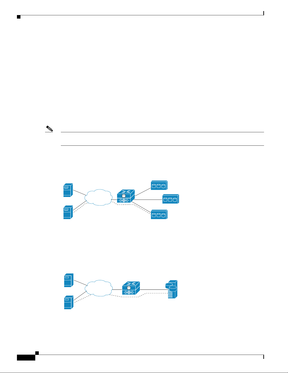
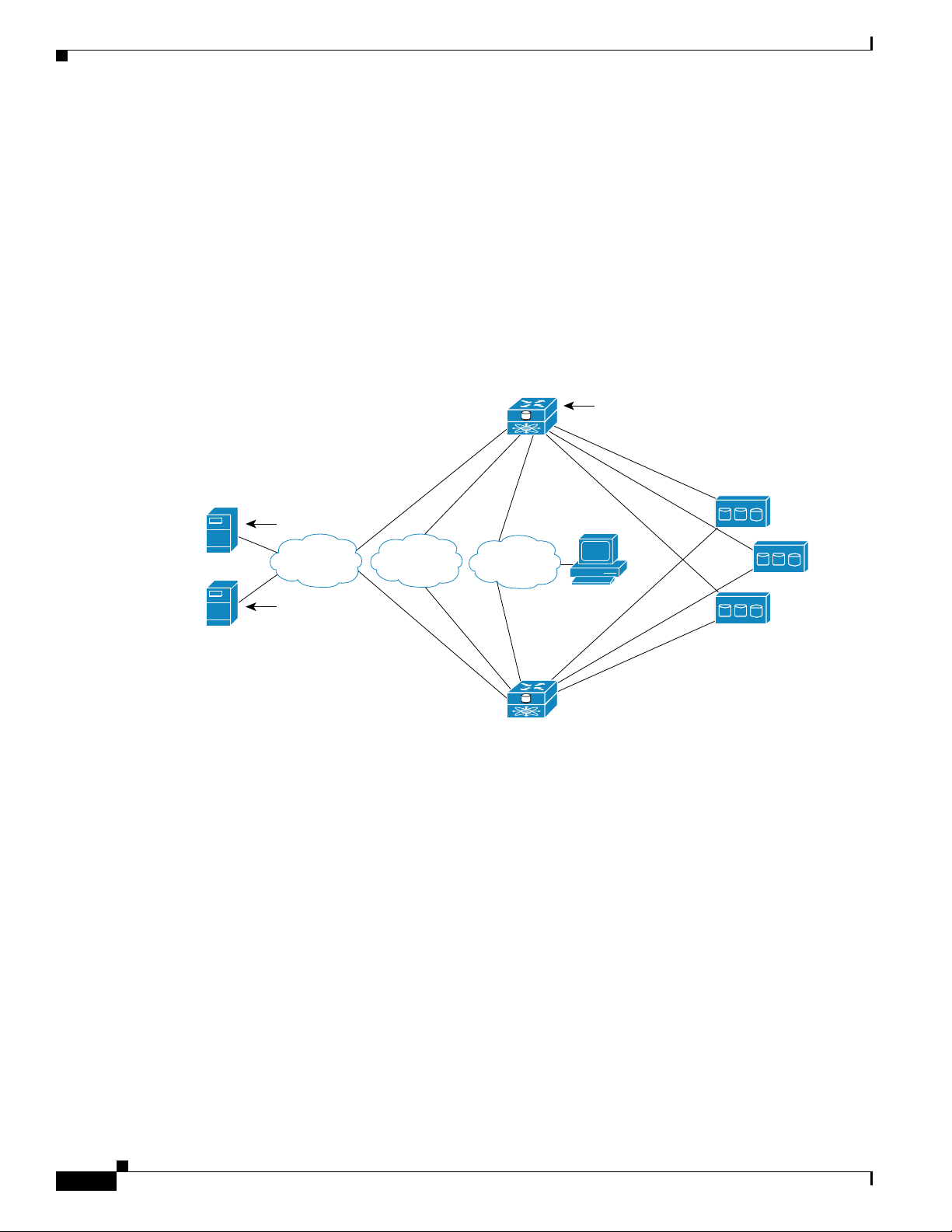
Basic Network Structure
Figure 1-7 shows the basic structure of a SCSI routing network. IP hosts with iSCSI drivers access the
storage routers through an IP network connected to the Gigabit Ethernet interface of each storage router.
The storage routers access storage devices connected to the Fibre Channel interfaces of each storage
router. A management station manages the storage routers through an IP network connected to the
management interface of each storage router. For high availability (HA) operation, the storage routers
communicate with each other over two networks: the HA network connected to the HA interface of each
storage router and the management network connected to the management interface of each storage
router.
Figure 1-7 SCSI Routing Basic Network Structure
Chapter 1 Before Configuring SN 5428-2 Storage Router Software
Cisco SN 5428-2
Contains SN 5428-2
software
IP host
IP host
Contains iSCSI
driver
IP
Contains iSCSI
driver
HA
Management
Cisco SN 5428-2
SCSI Routing Mapping and Access Control
SCSI routing occurs in the SN 5428-2 Storage Router through the mapping of physical storage devices
to iSCSI targets. An iSCSI target is an arbitrary name for a group of physical storage devices. You can
map an iSCSI target to multiple physical devices. An iSCSI target always contains at least one Logical
Unit Number (LUN). Each LUN on an iSCSI target is mapped to a single LUN on a physical storage
target.
You can choose either of two types of storage mapping: target-and-LUN mapping or target-only
mapping. Target-and-LUN mapping maps an iSCSI target and LUN combination to a physical storage
target and LUN combination. Target-only mapping maps an iSCSI target to a physical storage target and
its LUNs.
With target-and-LUN mapping, an iSCSI target name and iSCSI LUN number are specified and mapped
to the physical storage address of one LUN; either a WWPN + LUN (World Wide Port Name + LUN)
combination, a LUN ID (unique LUN identifier), or a LUN serial number.
FC storage
Management
station
85725
1-6
Cisco SN 5428-2 Storage Router Software Configuration Guide
OL-4691-01
Page 7
Chapter 1 Before Configuring SN 5428-2 Storage Router Software
If the LUN is available, it is made available as an iSCSI LUN and numbered with the iSCSI LUN number
specified. For example, if an iSCSI target and iSCSI LUN specified as Database, LUN 9 were mapped
to the physical storage address, WWPN 3100112233445566, LUN 12, then LUN 12 would be available
as one iSCSI LUN. An iSCSI driver would see the iSCSI target named Database, with one iSCSI LUN
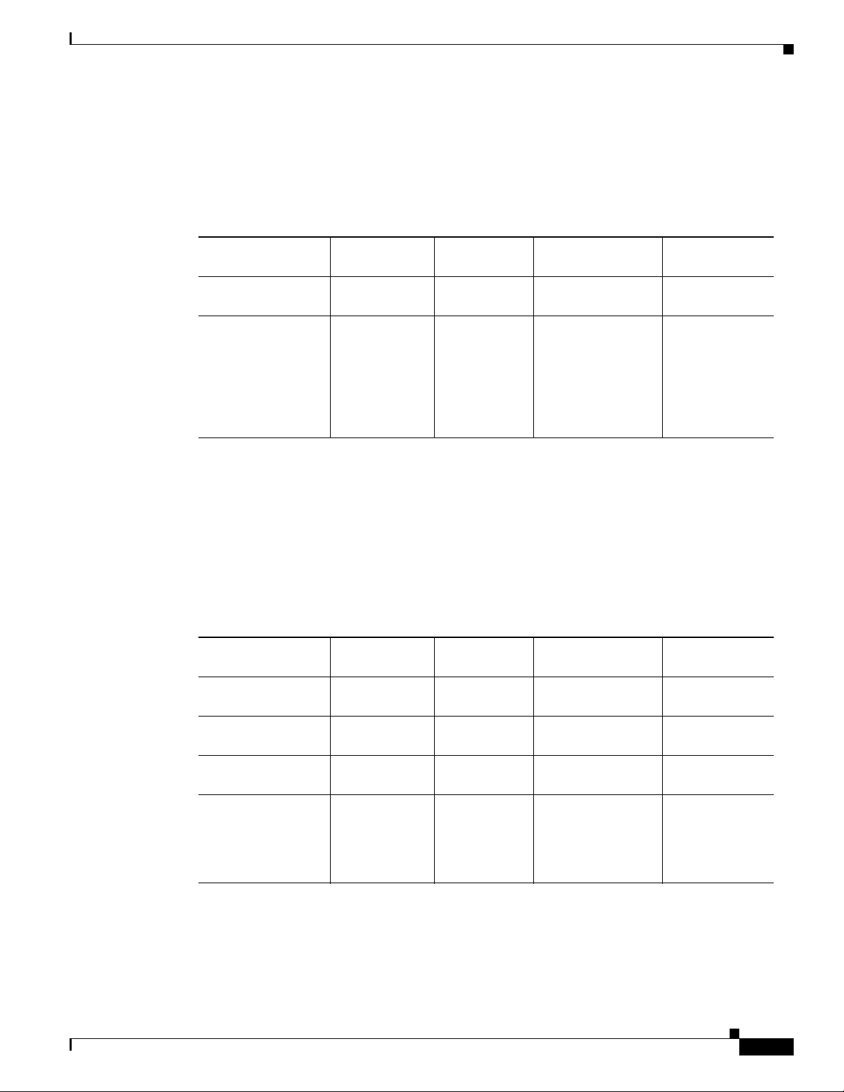
identified as LUN 9. The iSCSI LUN would appear as one storage device to a host. (See Table 1-1.)
Table 1-1 Target-and-LUN Mapping Example
SCSI Routing Overview
Apparent to Host as
Local Disk
Local Disk (D:) Database LUN 9 WWPN
iSCSI Target
Name
iSCSI LUN
Available
Physical Storage
Address
Physical LUN
Available
LUN 12
3100112233445566
Apparent as one
locally attached
storage device.
Database
appears as one
controller with
one LUN
available.
iSCSI LUN is
numbered as
specified and
can be different
than the
Specifies the storage
address of a storage
controller.
The LUN number
is specified as the
only LUN to be
mapped.
physical LUN
number.
With target-only mapping, an iSCSI target name is specified and mapped to the physical storage address
of a storage controller only; a WWPN. Any LUNs that are available in the storage controller are made
available as iSCSI LUNs and are numbered the same as the LUNs in the storage controller. For example,
if an iSCSI target specified as Webserver2000 were mapped to the physical storage address WWPN
3100112233445577, and LUNs 0 through 2 were available in that controller, those LUNs would become
available as three iSCSI LUNs. An iSCSI driver would see the iSCSI target named Webserver2000 as a
controller with three iSCSI LUNs identified as LUN 0, LUN 1, and LUN 2. Each iSCSI LUN would
appear as a separate storage device to a host. (See Tabl e 1-2 .)
Table 1-2 Target-only Mapping Example
OL-4691-01
Apparent to Host as
Local Disk
iSCSI Target
Name
iSCSI LUNs
Available
Physical Storage
Address
Local Disk (D:) Webserver2000 LUN 0 WWPN
3100112233445577
Local Disk (E:) Webserver2000 LUN 1 WWPN
3100112233445577
Local Disk (F:) Webserver2000 LUN 2 WWPN
3100112233445577
Apparent as three
locally attached
storage devices.
Webs er ve r2 00 0
appears as one
controller with
LUNs 0, 1, and
iSCSI LUNs
are numbered
the same as
physical LUNs.
Specifies the storage
address of a storage
controller.
2 available.
Cisco SN 5428-2 Storage Router Software Configuration Guide
Physical LUNs
Available
LUN 0
LUN 1
LUN 2
LUNs 0, 1, and 2
are available for
mapping.
1-7
Page 8

SCSI Routing Overview
Chapter 1 Before Configuring SN 5428-2 Storage Router Software
Access for SCSI routing is controlled in the IP hosts and the storage router. In an IP host, the iSCSI driver
is configured with the Gigabit Ethernet IP address of the SCSI routing instance in the storage router with
which the host is to transport SCSI requests and responses. In a storage router, access is controlled
through an access list and a VLAN identifier (VID) number of the hosts. Additionally, access can be
further controlled in the SN 5428-2 through authentication. See the “Authentication Overview” section
on page 1-24 for more information about authentication.
An access list enables access to storage devices attached to the SN 5428-2 according to any combination
of host IP address(es), CHAP user name(s), or iSCSI name(s). An access list contains these combinations
of hosts allowed to access the storage devices. Host VID enables access to storage devices according to
the VID of each host. See the “VLAN Access Overview” section on page 1-20 for more information
about VLAN access.
For each iSCSI target, you can associate one access list allowing read/write access, and one access list
allowing read-only access. See Chapter 6, “Configuring SCSI Routing,” for more information about
read/write and read-only access.
You can use a combination of access lists and VIDs to configure access in the SN 5428-2; that is, you
can specify that certain hosts according to IP address in a VLAN can access storage devices attached to
the SN 5428-2.
Once the access is configured in the hosts and the SN 5428-2, and once the storage mapping is
configured in the SN 5428-2, the SN 5428-2 routes SCSI requests and responses between hosts and the
mapped storage devices.
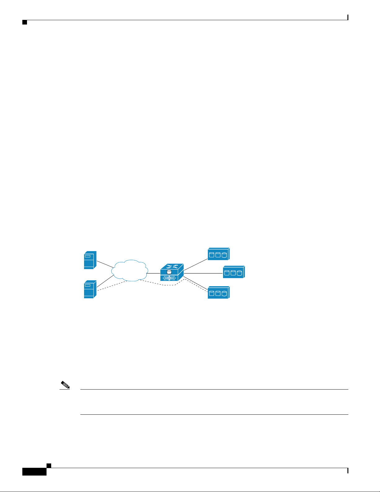
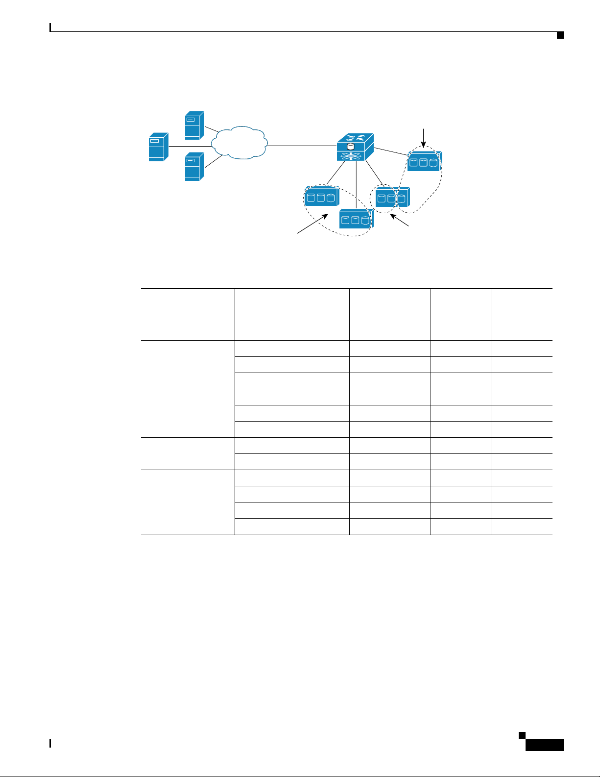
Figure 1-8 represents the concept of storage mapping and access control for SCSI routing. In the figure,
the SN 5428-2 Storage Router provides three IP hosts with IP access to disk drives across four disk
controllers. The SN 5428-2 contains two SCSI routing instances: one configured with IP address
10.1.2.3 for the Gigabit Ethernet interface and the other with IP address 10.1.2.4. The iSCSI drivers in
each IP host are configured to access those SCSI routing instances by their IP addresses through the
Gigabit Ethernet interface. An access list in the storage router or VID (or both) specifies that hosts A,
B, and C are allowed to access the mapped storage devices. From the perspective of a host, each disk
drive mapped to it appears as a locally attached disk drive. Table 1-3 shows the correlation between an
access list and/or VID, the Gigabit Ethernet IP addresses of the SCSI routing instances, and the storage
device mapping.
Note The purpose of Figure 1-8 and Table 1-3 is only to illustrate the concept of storage mapping and access
control. The IP addresses will vary according to each site. Similarly, the type of storage addressing (for
example, LUN ID, WWPN + LUN or LUN serial number) will vary according to the types of storage
and the types of storage addressing preferred at each site. In addition, the figure and the table exclude
any additional SN 5428-2 Storage Routers that could be configured for high availability.
1-8
Cisco SN 5428-2 Storage Router Software Configuration Guide
OL-4691-01
Page 9
Chapter 1 Before Configuring SN 5428-2 Storage Router Software
Figure 1-8 SCSI Routing Storage Mapping and Access Control Concept
SCSI Routing Overview
IP host A
IP host B
IP
Controller 1
IP host C
Storage
accessible by
IP host A
Table 1-3 SCSI Routing Storage Mapping and Access Control Concept
Cisco SN 5428-2
with IP addresses
10.1.2.3 and 10.1.2.4
123
123
Controller 2
123
Storage
accessible by
IP host C
Controller 4
123
Controller 3
Storage
accessible by
IP host B
85726
Hosts Allowed
Access via SN 5428-2
Access List and/or
VID
Storage Devices Apparent
to Host as Locally
Attached Devices
Via GbE IP
Addresses of SCSI
Routing Instances
Mapped To
Controller
Host A Local Disk (D:) 10.1.2.3 1 1
Local Disk (E:) 10.1.2.3 1 2
Local Disk (F:) 10.1.2.3 1 3
Local Disk (G:) 10.1.2.3 2 1
Local Disk (H:) 10.1.2.3 2 2
Local Disk (I:) 10.1.2.3 2 3
Host B Local Disk (D:) 10.1.2.3 3 1
Local Disk (E:) 10.1.2.3 3 2
Host C Local Disk (D:) 10.1.2.4 4 1
Local Disk (E:) 10.1.2.4 4 2
Local Disk (F:) 10.1.2.4 4 3
Local Disk (G:) 10.1.2.4 3 3
Mapped To
Drive
Available Instances of SCSI Routing
You can configure an SN 5428-2 Storage Router with up to 12 instances of SCSI routing services. Each
instance needs to be configured with the following:
• One or more unique IP addresses assigned to either one or both Gigabit Ethernet interfaces
• Mapping between iSCSI target names and physical storage addresses
• Access control
When an SN 5428-2 is part of a cluster, an instance of SCSI routing can run on only one storage router
in a cluster at any given time. See the “SN 5428-2 Cluster Management Overview” section on page 1-25
for more information about storage router clusters.
OL-4691-01
Cisco SN 5428-2 Storage Router Software Configuration Guide
1-9
Page 10

Transparent SCSI Routing Overview
Transparent SCSI Routing Overview
Transparent SCSI routing provides IP hosts with access to intelligent storage arrays as if each storage
array were directly attached to the hosts, with access to the storage devices managed primarily in each
storage array. The SN 5428-2 transparently presents each IP host to the storage array as if each host were
an FC host.
Typically, transparent SCSI routing is used with an intelligent storage array that is directly connected to
the SN 5428-2 Fibre Channel interface. Managing access to storage devices consists of using
configuration tools available with an intelligent storage array (to configure, for example, which hosts are
granted access and to configure multiple paths between hosts and storage devices). With transparent
SCSI routing, an intelligent storage array can manage each IP host as if it were directly attached to the
array as an FC host.
Transparent SCSI routing automatically creates iSCSI targets and maps them to physical targets
available in the intelligent storage array. The storage router presents the iSCSI targets to IP hosts as if
the physical targets were directly attached to the hosts. In conjunction with presenting iSCSI targets to
hosts, transparent SCSI routing presents each IP host as an FC host to the intelligent storage array. The
intelligent storage array is aware of each IP host and responds to each IP host as if it were an FC host
connected to the storage array. (See Figure 1-9.) Transparent SCSI routing can present no more than 62
IP hosts as FC hosts to an intelligent storage array.
Chapter 1 Before Configuring SN 5428-2 Storage Router Software
Figure 1-9 Transparent SCSI Routing Overview
IP hosts
Cisco SN 5428-2
IP
An IP host accesses
a target made available
by a storage array as if
the IP host were an FC
host directly attached
to the storage array.
Intelligent storage
array
FC
85727
To configure an SN 5428-2 Storage Router that is deployed for transparent SCSI routing, you should
have a basic understanding of the following concepts:
• Routing SCSI Requests and Responses, page 1-11
• Basic Network Structure, page 1-12
• Transparent SCSI Routing Mapping and Access Control, page 1-12
• Available Instances of Transparent SCSI Routing, page 1-15
1-10
Cisco SN 5428-2 Storage Router Software Configuration Guide
OL-4691-01
Page 11

Chapter 1 Before Configuring SN 5428-2 Storage Router Software
Routing SCSI Requests and Responses
Transparent SCSI routing consists of routing SCSI requests and responses between hosts in an IP
network and an intelligent storage array that is directly connected to an SN 5428-2 Fibre Channel
interface. (See Figure 1-10.)
Figure 1-10 Routing SCSI Requests and Responses for Transparent SCSI Routing
Transparent SCSI Routing Overview
IP hosts
Cisco SN 5428-2
IP
SCSI requests and responses
Intelligent storage
array
FC
85728
Each host that requires IP access to storage via an SN 5428-2 Storage Router needs to have a compatible
iSCSI driver installed. Using the iSCSI protocol, the iSCSI driver allows an IP host to transport SCSI
requests and responses over an IP network. From the perspective of a host operating system, the iSCSI
drive appears to be a locally attached SCSI or Fibre Channel drive to the host. From the perspective of
the storage array, each IP host appears as an FC host (with one Fibre Channel address for each host).
Transparent SCSI routing consists of the following main actions (Figure 1-11):
• Transporting SCSI requests and responses over an IP network between the hosts and the SN 5428-2
Storage Router.
• Routing SCSI requests and responses between hosts on an IP network and an intelligent storage
array.
• Transporting SCSI requests and responses between the SN 5428-2 Storage Router and an intelligent
storage array.
OL-4691-01
Figure 1-11 Transparent SCSI Routing Actions
IP hosts
Cisco SN 5428-2
IP
Transporting SCSI
requests and responses
over an IP network
Routing SCSI requests
and responses
Transporting SCSI
requests and responses
between an SN 5428-2
and a storage array
Cisco SN 5428-2 Storage Router Software Configuration Guide
Intelligent storage
array
FC
85729
1-11
Page 12

Transparent SCSI Routing Overview
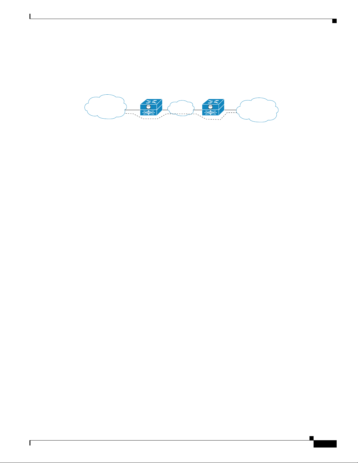
Basic Network Structure
Figure 1-12 shows the basic structure of a transparent SCSI routing network. IP hosts with iSCSI drivers
access the storage routers through an IP network connected to one of the Gigabit Ethernet interfaces of
each storage router. The storage routers access the intelligent storage array through a Fibre Channel
interface of each storage router. A management station manages the storage routers through an IP
network connected to the management interface of each storage router. High availability operation for
transparent SCSI routing is controlled in the intelligent storage array; therefore, an SN 5428-2 HA
network is not necessary, and the HA interface on the SN 5428-2 is disabled.
Figure 1-12 Transparent SCSI Routing Basic Network Structure
Chapter 1 Before Configuring SN 5428-2 Storage Router Software
Cisco SN 5428-2
IP host
IP host
Contains iSCSI
driver
IP
Contains iSCSI
driver
Management
Cisco SN 5428-2
FC
Management
station
FC
Transparent SCSI Routing Mapping and Access Control
Transparent SCSI routing occurs in an SN 5428-2 Storage Router through two types of mapping:
• Mapping iSCSI targets to physical targets
• Mapping each IP host to a Fibre Channel (FC) address
Mapping iSCSI targets to physical targets makes the physical targets accessible to IP hosts. Mapping
each IP host to an FC address—which maps the iSCSI client in the IP host to the internal FC initiator
WWPN—allows the host to be presented to a storage array as an FC host with its own FC WWPN.
Mapping iSCSI targets to physical targets consists of creating iSCSI targets that represent physical
targets in an intelligent storage array. An iSCSI target is an arbitrary name for a group of physical storage
devices; one iSCSI target is automatically created for each target made available by the intelligent
storage array.
The iSCSI target name is created automatically using the iSCSI extended unique identifier (EUI) format.
The EUI format combines the prefix “eui” with each WWPN made available by the intelligent storage
array. For example, if the WWPN of a target in a storage array were 3100112233445566, then an iSCSI
target would be created in the SN 5428-2 with the iSCSI target name of eui.3100112233445566.
Intelligent storage
array
85730
1-12
Transparent SCSI routing maps iSCSI targets to physical targets using target-only mapping. Target-only
mapping maps an iSCSI target to a physical storage target and its LUNs. Any LUNs that are available
with a physical WWPN in the storage array are available with the corresponding iSCSI target and are
numbered the same as the LUNs in the storage array.
Cisco SN 5428-2 Storage Router Software Configuration Guide
OL-4691-01
Page 13

Chapter 1 Before Configuring SN 5428-2 Storage Router Software
For example, if an iSCSI target were created for WWPN 3100112233445566 in a storage array, and that
WWPN contained LUNs 0 through 2, those LUNs would become available to an IP host as LUNs 0
through 2. An iSCSI driver would see the iSCSI target named eui.3100112233445566 as a controller
with three iSCSI LUNs identified as LUN 0, LUN 1, and LUN 2. Each iSCSI LUN would appear as a
separate storage device to an IP host.
Mapping each IP host to a Fibre Channel address consists of assigning a WWPN to an IP host that is
requesting access to storage; the WWPN is used for presenting the IP host as an FC host to a storage
array. The SN 5428-2 maintains a pool of 62 WWPNs that are assigned to IP hosts requesting access to
storage. When an IP host is granted access, a WWPN is assigned to the IP host and the SN 5428-2
presents the host as an FC host to the storage array. That host continues using that WWPN until it is
finished using the storage. When transparent SCSI routing is deployed in dynamic mode, once the host
is finished using the storage (logged out), the WWPN becomes available for assignment to other IP hosts
requiring access to storage. In static mode, the IP host/WWPN mapping is retained throughout IP host
logins and logouts and throughout storage router reboots.
See Table 1-4 for an example of transparent SCSI routing mapping. In this mapping example, the
WWPN, 200100023D000100, is assigned to the IP host. Using that WWPN, the SN 5428-2 presents the
IP host as an FC host to the storage array. Three devices are made available as local storage devices:
Local Disk (E:), Local Disk (F:), and Local Disk (G:). (Microsoft Windows devices are used as
examples.) The iSCSI target, eui.3100112233445566, has been automatically created and mapped to a
WWPN, 3100112233445566, that was made available by the storage array. To the IP host, the iSCSI
target appears as a controller with LUNs 0, 1, and 2 available. The LUNs are apparent as they are with
the WWPN in the storage array.
Transparent SCSI Routing Overview
Table 1-4 Transparent SCSI Routing Mapping Example
LUNs
WWPN assigned to IP
Host
Apparent
Apparent to IP
Host iSCSI Target Name
with iSCSI
Target
WWPN of Storage Array
Target
Physical
LUNs
Available
200100023D000100 Local Disk (E:) eui.3100112233445566 LUN 0 3100112233445566 LUN 0
Local Disk (G:) eui.3100112233445566 LUN 1 3100112233445566 LUN 1
Local Disk (H:) eui.3100112233445566 LUN 2 3100112233445566 LUN 2
Access for transparent SCSI routing is controlled in the IP hosts and the intelligent storage array. In an
IP host, the iSCSI driver is configured with the Gigabit Ethernet IP address of the SCSI routing instance
in the storage router with which the host is to transport SCSI requests and responses. In the intelligent
storage array, access is controlled through its storage management tools. Additionally, access can be
further controlled in the SN 5428-2 through authentication. See the “Authentication Overview” section
on page 1-24 for more information about authentication.
Once the access is configured in the hosts and the intelligent storage array, the SN 5428-2 transparently
routes SCSI requests and responses between hosts and the mapped storage devices.
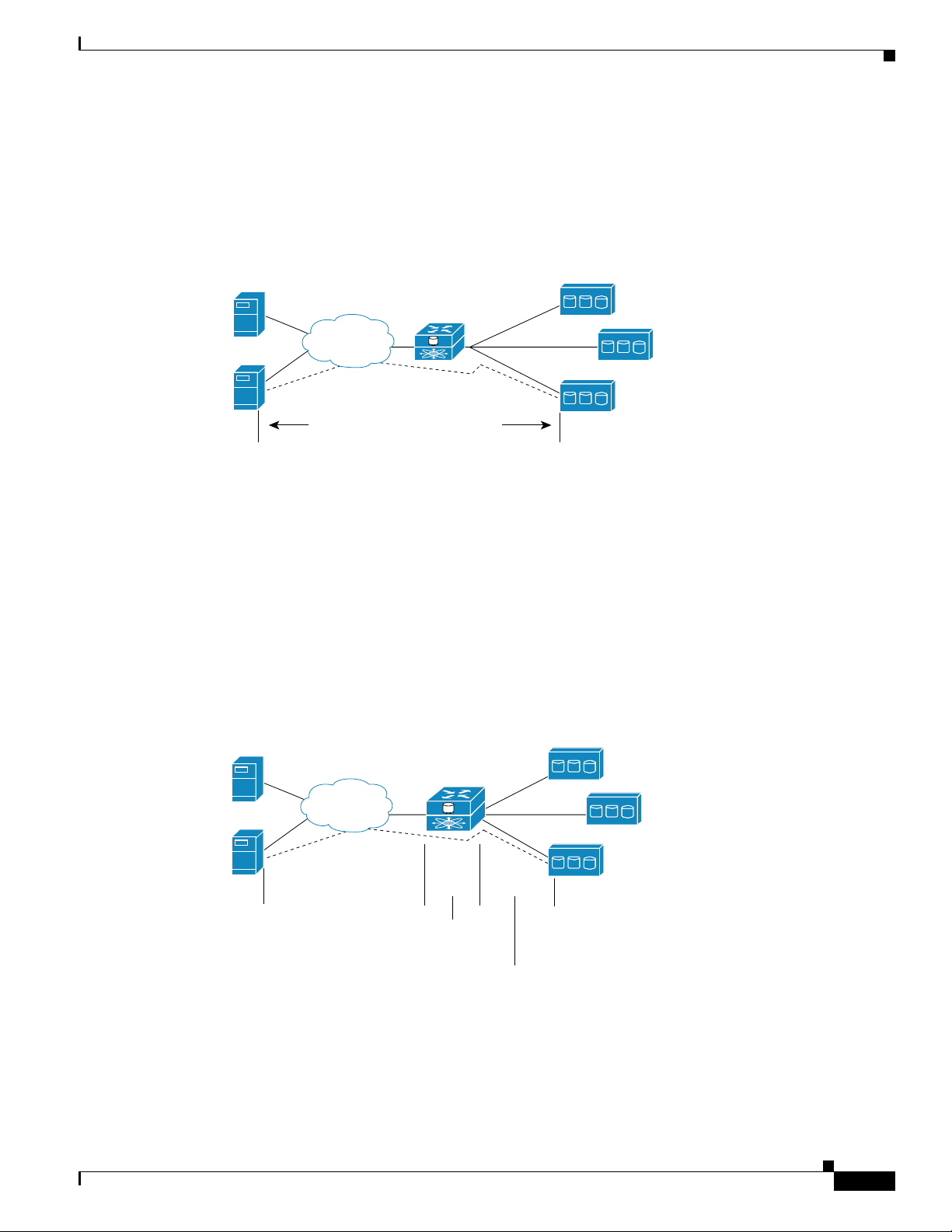
Figure 1-13 represents the concept of storage mapping and access control for transparent SCSI routing.
In the figure, the SN 5428-2 Storage Router provides three IP hosts with access to disk drives made
available by the intelligent storage array. A single SCSI routing instance in the storage router is
configured with IP address 10.1.2.3 for the Gigabit Ethernet interface. The iSCSI driver in each IP host
is configured to access that SCSI routing instance by its IP address 10.1.2.3 through the Gigabit Ethernet
interface on the storage router. From the perspective of an IP host, each disk drive mapped to it appears
as a locally attached disk drive. From the perspective of the storage array, each host is connected directly
OL-4691-01
Cisco SN 5428-2 Storage Router Software Configuration Guide
1-13
Page 14

Chapter 1 Before Configuring SN 5428-2 Storage Router Software
Transparent SCSI Routing Overview
to it, with each host having a WWPN. Table 1-5 shows the correlation between the IP hosts, the Gigabit
Ethernet IP address of the SCSI routing instance, storage device mapping, and IP-host-to-FC-address
(WWPN) mapping.
Note The purpose of Figure 1-13 and Tabl e 1- 5 is only to illustrate the concept of storage mapping, FC
address mapping, and access control. The IP addresses and WWPNs will vary according to each site. In
addition, the figure and the table exclude any additional SN 5428-2 Storage Routers that could be
configured for multiple paths between hosts and storage devices.
Figure 1-13 Transparent SCSI Routing Storage Mapping and Access Control Concept
WWPN 3100112233445566
and its LUNs accessible by IP host A
WWPN 3100112233445577
and its LUNs accessible by IP host B
IP host B
IP host A
IP
Cisco SN 5428-2
with IP address
10.1.2.3
Storage
array
FC
IP host C
Table 1-5 Transparent SCSI Routing Storage Mapping and Access Control Concept
Hosts Allowed Access by
Intelligent Storage Array and
SN 5428-2 Authentication
Host A: apparent to storage
array as FC host with WWPN
201000023D000100
SN 5428-2 presents IP hosts as
FC hosts with WWPNs:
IP host A = WWPN 201000023D000100
IP host B = WWPN 201000023D000101
IP host C = WWPN 201000023D000102
Storage Devices
Apparent to Host as
Locally Attached
Devices
Via GbE IP
Address of
SCSI Routing
Instance
Local Disk (D:) 10.1.2.3 3100112233445566 0
Local Disk (E:) 10.1.2.3 3100112233445566 1
WWPN 3100112233445588
and its LUNs accessible by IP host C
Mapped To Storage
WWPN Drive (LUN)
Local Disk (F:) 10.1.2.3 3100112233445566 2
Host B: apparent to storage
array as FC host with WWPN
201000023D000101
Host C: apparent to storage
array as FC host with WWPN
201000023D000102
Local Disk (D:) 10.1.2.3 3100112233445577 0
Local Disk (E:) 10.1.2.3 3100112233445577 1
Local Disk (D:) 10.1.2.3 3100112233445588 0
Local Disk (E:) 10.1.2.3 3100112233445588 1
Local Disk (F:) 10.1.2.3 3100112233445588 2
Local Disk (G:) 10.1.2.3 3100112233445588 3
85731
1-14
Cisco SN 5428-2 Storage Router Software Configuration Guide
OL-4691-01
Page 15

Chapter 1 Before Configuring SN 5428-2 Storage Router Software
Available Instances of Transparent SCSI Routing
When an SN 5428-2 Storage Router is deployed for transparent SCSI routing, it is automatically
configured for one instance of transparent SCSI routing service; only that one instance can exist in that
SN 5428-2.
While the instance of transparent SCSI routing needs to be configured with a Gigabit Ethernet IP
address, mapping between iSCSI target names and physical storage addresses is automatic and cannot
be configured.
When an SN 5428-2 is deployed for transparent SCSI routing, it cannot participate in a storage router
cluster. However, multiple SN 5428-2s can be connected to an intelligent storage array, where it is
possible to manage failover and multiple paths. In networks where multiple SN 5428-2 Storage Routers
are connected to an intelligent storage array, each SN 5428-2 has one (and only one) instance of
transparent SCSI routing; the instance is unique to that storage router and cannot fail over to another
storage router.
FCIP Overview
FCIP Overview
Fibre Channel over IP (FCIP) enables SN 5428-2 Storage Routers to provide connectivity between FC
hosts and FC storage devices over an IP network.
To deploy FCIP, two SN 5428-2 Storage Routers, or one SN 5482-2 Storage Router and one MDS 9000
Series system, are required. Each system is configured for FCIP and connected to a SAN (or to any FC
host or FC device). The peer systems are connected to each other through an IP network. (See
Figure 1-14.)
Figure 1-14 FCIP Overview
FC hosts and
storage devices
SAN 1
An FC host or FC device needs no additional hardware or software to access storage devices via an
SN 5428-2 Storage Router deployed for FCIP.
To configure an SN 5428-2 Storage Router deployed for FCIP, you need a basic understanding of the
following concepts:
• Using FCIP to Route Fibre Channel Packets, page 1-15
SN 5428-2
IP
Peer SN 5428-2s deployed for FCIP
provide connectivity between SANs
over an IP network
SN 5428-2
FC hosts and
storage devices
SAN 2
91007
• FCIP Network Structures, page 1-16
Using FCIP to Route Fibre Channel Packets
With FCIP, peer systems transport FC frames over an IP network. From the perspective of the SANs, the
storage devices accessed through the peer systems appear to be part of one unified SAN.
Cisco SN 5428-2 Storage Router Software Configuration Guide
OL-4691-01
1-15
Page 16

FCIP Overview
Chapter 1 Before Configuring SN 5428-2 Storage Router Software
Once configured, FCIP instances on each system become active and establish their connectivity via the
IP network. The storage devices in one SAN access the storage devices in the connected SAN using FC
frames, which are encapsulated in IP packets by the FCIP instance, and transmitted to the peer system.
The peer FCIP instance strips the IP packet data and passes only the FC frames over the FC interfaces
to the storage devices.
The peer systems deployed for FCIP must be configured to use the same protocol: TCP or raw. TCP
protocol uses standard TCP flow control and error recovery algorithms, and should be used if you require
a standards-based FCIP implementation or connect to a non-SN 5428-2 peer, such as the MDS 9000
Series system. Raw protocol uses a proprietary connection protocol, but provides more operational
control over flow control and error recovery than standard TCP/IP.
If the selected protocol is TCP, one FCIP instance must be configured as the TCP client; the other FCIP
instance must be configured as the TCP server. The only difference between FCIP instances configured
as TCP client and TCP server is which FCIP instance initiates the connection: the TCP client initiates
the connection.
FCIP transports FC frames between SANs by performing the following actions (Figure 1-15):
• Transporting FC frames between a SAN and an SN 5428-2 that is deployed for FCIP
• Encapsulating FC frames in IP packets and transporting the IP packets to a peer SN 5428-2 or
MDS 9000 Series system that is deployed for FCIP
• Receiving IP packets and transporting as FC frames between the peer SN 5428-2 or MDS 9000
Series system and a connected SAN
Note that FC traffic is carried over the IP network in such a way that the FC fabric and all FC devices on
the fabric are unaware of the presence of the IP Network.
Figure 1-15 FCIP Actions
FC hosts and
storage devices
SAN
Transporting FC frames
between SAN and an
SN 5428-2 deployed
for FCIP.
FCIP Network Structures
This section describes typical FCIP network structures. In all of these examples, a management station
(not shown) manages the storage routers through an IP network connected to the management interface
and/or HA interface of each storage router.
SN 5428-2 SN 5428-2
IP
Encapsulating FC frames
in IP packets and
transporting IP packets
to peer SN 5428-2.
FC hosts and
storage devices
SAN
Transporting FC
frames between
an SN 5428-2
deployed for FCIP
and SAN.
91008
1-16
Cisco SN 5428-2 Storage Router Software Configuration Guide
OL-4691-01
Page 17

Chapter 1 Before Configuring SN 5428-2 Storage Router Software
Figure 1-14 represents a basic, non-redundant structure of an FCIP network configuration. In this
example, an FC host or FC device connects to one or more Fibre Channel interfaces of each peer
SN 5428-2 Storage Router deployed for FCIP. Each SN 5428-2 connects to the IP network through one
of its Gigabit Ethernet interfaces. Through the IP network, each FCIP instance accesses its peer, thereby
connecting the SANs.
Figure 1-16 shows a slightly more complex FCIP network: a redundant WAN FCIP configuration. In this
example configuration, an FC host or FC device connects to one or more Fibre Channel interfaces of
each peer SN 5428-2 Storage Router deployed for FCIP, and each SN 5428-2 connects to two separate
IP networks through each of its Gigabit Ethernet interfaces. Through the IP network, each FCIP instance
accesses the peer storage router deployed for FCIP, connecting the SANs. In this configuration, IP A and
IP B are redundant paths, so that the loss of connectivity via either path does not cause a loss of
connectivity between the SANs.
Figure 1-16 FCIP Redundant WAN Configuration
FCIP Overview
IP
A
SN 5428-2
SAN 1
IP
B
SN 5428-2
SAN 2
91533
Figure 1-17 shows an even more reliable FCIP configuration, in which pairs of SN 5428-2s provide full
redundancy. In this configuration, loss of an SN 5428-2 or loss of connectivity through one of the IP
networks can be tolerated with no loss of connectivity between the SANs.
Figure 1-17 FCIP Fully Redundant Configuration
deployed for FCIP
FC hosts and
storage devices
SAN 1
SN 5428-2
IP
A
SN 5428-2
deployed for FCIP
FC hosts and
storage devices
SAN 2
OL-4691-01
SN 5428-2
deployed for FCIP
IP
B
SN 5428-2
deployed for FCIP
Cisco SN 5428-2 Storage Router Software Configuration Guide
91009
1-17
Page 18

Mixed Mode Overview
Note For multiple paths between SANs, multiple pairs of systems deployed for FCIP need to be connected to
Chapter 1 Before Configuring SN 5428-2 Storage Router Software
the FC hosts or FC devices. However, multiple SN 5428-2 Storage Routers deployed for FCIP cannot be
configured in an HA cluster. It is assumed that the multipath management is being done by an entity
outside the SN 5428-2s (for example, by management applications on the FC host or storage devices).
Figure 1-18 shows an alternative network structure for FCIP, in which FCIP tunnels are established from
two SANs aggregated to a central site. The SN 5428-2 at the central site has one FCIP instance set up
for SAN 1, and the other FCIP instance set up for SAN 2.
Figure 1-18 Multisite FCIP Configuration
SN 5428-2
SAN 1
FC hosts and
storage devices
SN 5428-2
SAN 2
Mixed Mode Overview
When the SN 5428-2 is deployed for SCSI routing or transparent SCSI routing, you can optionally
configure one of the internal FC initiator interfaces for FCIP. When it is deployed for FCIP, one of the
internal FC initiator interfaces can be configured for SCSI routing. This mixed mode deployment allows
the storage router to provide IP hosts with access to the FC storage via one initiator interface, and FCIP
connectivity for FC hosts and FC storage devices via the other initiator interface.
Figure 1-19 shows a storage router deployed for mixed mode, with one internal FC initiator interface
dedicated to SCSI routing and the other internal interface dedicated to FCIP.
Figure 1-20 shows a storage router deployed for mixed mode, with one internal FC initiator interface
dedicated to transparent SCSI routing and the other internal interface dedicated to FCIP.
IP
SN 5428-2
FC hosts and
storage devices
SAN 3
91357
1-18
When the storage router is deployed for mixed mode, all of the features and functionality of the primary
deployment mode (SCSI routing, transparent SCSI routing or FCIP), and the additional mode, are
available.
Cisco SN 5428-2 Storage Router Software Configuration Guide
OL-4691-01
Page 19

Chapter 1 Before Configuring SN 5428-2 Storage Router Software
Figure 1-19 Mixed Mode Overview (SCSI routing and FCIP)
One internal FC initiator interface is
deployed for SCSI routing, providing
IP hosts with access to FC storage as
if they were directly attached.
FC hosts and
storage devices
IP hosts
Mixed Mode Overview
FC storage
SAN 1
SN 5428-2
One internal FC initiator
IP
SN 5428-2
SAN 2
FC hosts and
storage devices
interface is deployed for FCIP, providing
connectivity between SANs over an IP
network
Figure 1-20 Mixed Mode Overview (Transparent SCSI routing and FCIP)
One internal FC initiator
interface is deployed for transparent
SCSI routing, providing access to a
storage array as if the IP host were an
FC host directly attached to the storage array
IP hosts
Intelligent
storage array
FC hosts and
storage devices
SAN 1
IP
SAN 2
99419
OL-4691-01
SN 5428-2
SN 5428-2
One internal FC initiator
interface is deployed for FCIP, providing
connectivity between SANs over an IP
network
Cisco SN 5428-2 Storage Router Software Configuration Guide
FC hosts and
storage devices
99420
1-19
Page 20

VLAN Access Overview
Basic Network Structure
When a storage router is deployed for SCSI routing or transparent SCSI routing and FCIP, IP hosts with
iSCSI drivers access the storage router through the IP network connected to the storage router’s Gigabit
Ethernet interfaces. The storage router accesses the storage devices or intelligent storage array connected
to the Fibre Channel interfaces. Access to the FC interfaces is made through the internal FC initiator
interface configured for iSCSI traffic.
The internal FC initiator interface configured for FCIP allows the FC hosts or FC devices to connect to
one or more Fibre Channel interfaces of the peer systems, which are connected to the IP network through
a Gigabit Ethernet interface. Through the IP network, each FCIP instance accesses its peer, thereby
connecting the SANs. Redundant network structures are also supported.
A management station manages the storage router through an IP network connected to the management
interface. A storage router deployed for SCSI routing and FCIP can also participate in a cluster to
provide HA operations for SCSI routing. When the storage router is deployed for transparent SCSI
routing and FCIP, the HA operations for SCSI routing are controlled in the intelligent storage array. and
the HA interface on the storage router is disabled.
Chapter 1 Before Configuring SN 5428-2 Storage Router Software
VLAN Access Overview
SN 5428-2 VLAN access provides IP hosts with access to storage devices according to the VLAN to
which each host belongs.
Figure 1-21 shows a sample network that employs SN 5428-2 VLAN access. In the figure, an SN 5428-2
Gigabit Ethernet interface is connected to an IP network through an IEEE 802.1Q trunk; the SN 5428-2
Fibre Channel interfaces are connected to storage devices 1, 2, and 3. The SN 5428-2 is configured with
two SCSI routing instances named SR100 and SR200. The IP network contains two VLANs: VLAN 100
and VLAN 200. The SCSI routing instance, SR100, is configured to allow the hosts in VLAN 100 to
access storage devices 1 and 2. The SCSI routing instance, SR200, is configured to allow the hosts in
VLAN 200 to access storage device 3.
1-20
Cisco SN 5428-2 Storage Router Software Configuration Guide
OL-4691-01
Page 21

Chapter 1 Before Configuring SN 5428-2 Storage Router Software
Figure 1-21 VLAN Access Overview
VLAN 200
Zoning Overview
Storage devices accessible by
VLAN 100 via SCSI routing
instance SR100
1
2
3
instance SR200
85732
VLAN 100
IP
802.1Q trunk
Configured with two SCSI
routing instances named
SR100 and SR200
Cisco SN 5428-2
Storage device accessible by
VLAN 200 via SCSI routing
If the SN 5428-2 is used in a Cisco switched network environment, configure the SN 5428-2 to use the
Cisco proprietary VLAN Trunking Protocol (VTP). With VTP, the SN 5428-2 will exchange VTP
packets with an externally attached switch to dynamically learn about the VLANs that are accessible in
the IP network. The SN 5428-2 then uses VTP to propagate VLAN information around the switched
network using layer 2 multicast packets.
If the SN 5428-2 is used in a non-Cisco switched network environment, configure the SN 5428-2 for
VLAN without using VTP. The SN 5428-2 does not exchange VTP packets to learn about the VLANs in
the network. Instead, you must manually assign VLANs in the network with a VLAN identifier (VID)
number. You can optionally assign each VLAN with a unique name and manually set the MTU size.
If the SN 5428-2 participates in a cluster, the VLAN information configured for the SN 5428-2 is
propagated to all storage routers in the cluster.
The SN 5428-2 uses IEEE 802.1Q standard for VLAN encapsulation. With 802.1Q encapsulation,
VLAN information is carried in packets sent and received through the SN 5428-2 Gigabit Ethernet
interface. These packets contain the VID and other VLAN information needed for VLAN members to
participate in a VLAN.
A VLAN is granted access to storage devices via a SCSI routing instance configured in the SN 5428-2.
The iSCSI targets assigned to the SCSI routing instance determine which storage devices the VLAN can
access.
Zoning Overview
The SN 5428-2 supports FC fabric zoning. Zoning enables you to divide the devices of the fabric into
zones for more efficient and secure communication among functionally grouped nodes.
Note FC fabric zoning participation is not supported in SN 5428-2s deployed for transparent SCSI routing.
OL-4691-01
Cisco SN 5428-2 Storage Router Software Configuration Guide
1-21
Page 22

Zoning Overview
Chapter 1 Before Configuring SN 5428-2 Storage Router Software
Once initiator WWPN1 and initiator WWPN2 are configured, the SN 5428-2 will support fabric zoning
using the WWPNs of each FC storage device attached, either directly or on a fabric. The IP hosts
participate in zoning via the access list. See the “SCSI Routing Mapping and Access Control” section
on page 1-6 for more information about access lists.
Figure 1-22 shows an example network that employs SN 5428-2 FC fabric zoning. In the figure, the
SN 5428-2 is connected to IP hosts A and B through the Gigabit Ethernet interface; the SN 5428-2 Fibre
Channel interfaces are connected to FC storage and a zoned FC switched fabric. The IP hosts are allowed
access to storage devices in both zones (Y and Z) and storage devices attached to the SN 5428-2. Zone
Y has access to all the SN 5428-2 storage devices and zone Z has access to one storage device on the
SN 5428-2.
Figure 1-22 FC Fabric Zoning Overview
Zone Y
Host A
FC storage
Zone Z
Host B
FC
switch
IP Host A IP Host B
IP
Cisco SN 5428-2
FC storage
Zoning comprises zones, zone sets, aliases, and zone databases.
85733
1-22
A zone is a named group of devices that can communicate with each other. Membership in a zone is
defined by the device WWPN. Zone members can communicate only with members of the same zone.
The SN 5428-2 supports the soft zone type. Soft zones can overlap; that is, a device can be a member of
more than one soft zone.
To make it easier to add devices to one or more zones, you can create an alias. An alias is a named set
of devices that are grouped together for convenience. You can add an alias to one or more zones.
However, you cannot add a zone to an alias, nor can an alias be a member of another alias.
You can also use an alias to name a single device. This allows you to refer to the device by the alias name
rather than the WWPN of the device.
A zone set is a named group of zones. A zone can be a member of more than one zone set.
Cisco SN 5428-2 Storage Router Software Configuration Guide
OL-4691-01
Page 23

Chapter 1 Before Configuring SN 5428-2 Storage Router Software
To apply zoning to a fabric, enable the appropriate zone set. When you enable (or “activate”) a zone set,
the system compiles zone sets of the same name from all SN 5428-2s and switches in the fabric, and then
redistributes this merged active zone set back to every SN 5428-2 and switch in the fabric. Therefore,
every SN 5428-2 and switch in the fabric will have identical active zone sets.
The SN 5428-2 supports multiple zone sets, but only one zone set can be active in the fabric at any given
time.
Each SN 5428-2, like other switches in the zoned FC switched fabric, has its own zoning database. The
zoning database is made up of all aliases, zones, and zone sets that have been created on the SN 5428-2
or received from other switches in the fabric. When you modify aliases, zone or zone sets, the changes
are immediately saved to the SN 5428-2 bootable configuration.
The Auto Save zoning configuration parameter controls whether zoning changes received from other
SN 5428-2s or switches in the fabric are automatically saved to the SN 5428-2s zoning database.
See Chapter 5, “Configuring Fibre Channel Interfaces,” for more information about configuring the
SN 5428-2 for FC fabric zoning.
Fibre Channel Interface Overview
Fibre Channel Interface Overview
The SN 5428-2 has an integrated switch component with Fibre Channel interfaces that support the
following port types: E_Port, F_Port, FL_Port, G_Port, GL_Port, TL_Port, and donor port. The storage
router supports a maximum of 7 FC Interswitch Link (ISL) hops.
The SN 5428-2 FC interfaces support GS-3 management server commands. This allows management of
the SN 5428-2 integrated switch component through the Fibre Channel interfaces (in-band
management). See the interface fc? ms-enable command in the Cisco SN 5400 Series Storage Router
Command Reference for more information about enabling the FC interfaces for GS-3 commands.
See Chapter 5, “Configuring Fibre Channel Interfaces,” for more information about configuring FC
ports.
Gigabit Ethernet Interface Overview
Each of the two 1-Gigabit Ethernet interfaces on the SN 5428-2 (GE 1 and GE 2) provide the following
capabilities:
• Multiple IP addresses per SCSI routing instance—allows IP hosts to connect to SCSI routing
instances via one or more IP addresses. Each Gigabit Ethernet interface can be configured with up
to 12 unique IP addresses, which provides a maximum of 24 unique IP addresses per SN 5428-2
Storage Router. If VLAN access is used, the maximum number of unique IP addresses per Gigabit
Ethernet interface increases to 16. This provides a maximum of 32 unique IP addresses per
SN 5428-2 Storage Router when configured with VLAN.
• Assignment of a secondary interface per SCSI routing instance—allows the same IP address to be
assigned to each Gigabit Ethernet interface; one interface is assigned as primary and one interface
is assigned as secondary. If the primary Gigabit Ethernet interface loses connection to the host and
if the secondary connection is assigned and still connected, the IP address moves to the secondary
Gigabit Ethernet interface, which then becomes active.
• Assignment as an interface to an FCIP peer—allows assignment of an IP address as a primary
Gigabit Ethernet interface between an FCIP instance and an FCIP peer. Each SN 5428-2 can be
configured with up to two FCIP instances, and each FCIP instance can be configured with one peer,
for a maximum of two FCIP peers per SN 5428-2 Storage Router when configured for FCIP.
OL-4691-01
Cisco SN 5428-2 Storage Router Software Configuration Guide
1-23
Page 24

Authentication Overview
• Assignment of a secondary interface per FCIP instance—allows the same IP address to be assigned
to each Gigabit Ethernet interface configured for an FCIP instance; one interface is assigned as
primary and one interface is assigned as secondary. If the primary interface loses connection to the
network and remains down for two seconds, the IP address moves to the secondary Gigabit Ethernet
interface, which then becomes active.
• Assignment as a management IP address—allows each Gigabit Ethernet interface to have one IP
address assigned per logical interface, as a management interface. This IP address is in addition to
any multiple IP address(es) per SCSI routing instance or FCIP instance assigned.
• Assignment of a secondary management IP address—allows the same IP address to be assigned to
each Gigabit Ethernet interface configured as a management interface; one interface is assigned as
primary and one interface is assigned as secondary. If connection to the primary Gigabit Ethernet
maintenance interface is lost and if the secondary maintenance interface connection is assigned and
connected, the IP address moves to the secondary Gigabit Ethernet interface, which then allows
management access.
Authentication Overview
Chapter 1 Before Configuring SN 5428-2 Storage Router Software
Authentication is a software service that is available in each SN 5428-2. It provides a method of
identifying users (including login and password dialog, challenge and response, and messaging support)
prior to receiving access to the requested object, function, or network service. The SN 5428-2 supports
three types of authentication:
• iSCSI authentication—provides an authentication mechanism to authenticate IP hosts that request
access to storage. An IP host, acting as an iSCSI initiator, can also verify the identity of an iSCSI
target assigned to a SCSI routing instance, which responds to the request, resulting in a two-way
authentication.
• Enable authentication—provides a mechanism to authenticate users requesting Administrator mode
access to an SN 5428-2 management session via the CLI enable command or an FTP session.
• Login authentication—provides a mechanism to authenticate users requesting access to the
SN 5428-2 in Monitor mode via the login process from a Telnet session, SSH session or the
SN 5428-2 console.
Authentication is provided by an AAA (authentication, authorization, and accounting) subsystem
configured in each SN 5428-2. AAA is Cisco’s architectural framework for configuring a set of three
independent security functions in a consistent and modular manner: authentication, authorization, and
accounting. The SN 5428-2 Storage Router software implements the authentication function.
AAA authentication is configured by defining a list of authentication services. iSCSI authentication,
which uses a AAA authentication services list, can be enabled for specific SCSI routing instances in an
SN 5428-2.
When iSCSI authentication is enabled, IP hosts (with iSCSI drivers) must provide user name and
password information each time an iSCSI TCP connection is established. With two-way authentication,
the SCSI routing instance to which an iSCSI target has been assigned responds to the authentication
request with an assigned username and password. iSCSI authentication uses the iSCSI CHAP (Challenge
Handshake Authentication Protocol) authentication method.
1-24
See Chapter 9, “Configuring Authentication,” for more information about configuring authentication
services.
Cisco SN 5428-2 Storage Router Software Configuration Guide
OL-4691-01
Page 25

Chapter 1 Before Configuring SN 5428-2 Storage Router Software
SN 5428-2 Cluster Management Overview
You can configure Cisco SN 5428-2 Storage Routers in a cluster to allow the storage routers to back each
other up in case of failure.
Note A storage router can participate in a cluster only if it is deployed for SCSI routing.
An SN 5428-2 Storage Router can be configured in a cluster with one other SN 5428-2, or with an
SN 5428, connected as follows:
• Connected to the same hosts
• Connected to the same storage systems
• Connected to each other through their management and high availability (HA) interfaces
In a cluster, storage routers continually exchange HA information to propagate configuration data to
each other and to detect failures in the cluster. The storage routers exchange HA information through
two separate networks: one connected to the management interface of each storage router and the other
connected to the HA interface of each storage router. To make sure that HA information is exchanged
reliably between storage routers, the storage routers balance the transmission of HA information
between the management and the HA interfaces.
A storage router cluster supports up to 12 active instances of SCSI routing. For example, if one storage
router is already running two instances, it is eligible to run up to ten additional instances. At any given
time, an instance of SCSI routing can run on only one storage router in a cluster. The instance continues
running on the storage router where it was started until one of the following actions occurs:
• The instance is explicitly stopped or failed over to the other storage router in the cluster.
SN 5428-2 Cluster Management Overview
• The instance automatically fails over to another storage router because an interface is unavailable or
another software or hardware problem occurs. This automatic fail over uses intelligent eligibility
guidelines to determine fail over.
See Chapter 10, “Configuring a High Availability Cluster,” for more information about configuring a
high availability cluster.
Interface Naming
Configuring the SN 5428-2 Storage Router software requires that you understand hardware interface
naming. This section describes the interface naming system used with the SN 5428-2 Storage Router
hardware.
Each storage router interface is assigned a three-character name consisting of two lower-case letters
followed by a number. The letters designate the interface type; the number designates the chassis slot
occupied by the interface (See Figure 1-23).
OL-4691-01
Cisco SN 5428-2 Storage Router Software Configuration Guide
1-25
Page 26

Where to Go Next
Chapter 1 Before Configuring SN 5428-2 Storage Router Software
Figure 1-23 SN 5428-2 Interface Naming System
aan
Interface type Chassis slot
Table 1-6 shows valid interface type designators for the SN 5428-2; Figure 1-24 shows each interface
location and interface name on the SN 5428-2.
Table 1-6 Interface Type Designators
Interface Type Description
fc Fibre Channel
ge Gigabit Ethernet
Figure 1-24 SN 5428-2 Chassis-Slot Numbering
ge1 ge2 fc1 fc2 fc3 fc4 fc5 fc6 fc7 fc8
Where to Go Next
48421
85739
1-26
When you are ready to configure the SN 5428-2 software, proceed to one of the following chapters in
this configuration guide according to your needs:
• Chapter 2, “First-Time Configuration”—For initial setup or after configuration has been reset to
factory default configuration
• Chapter 3, “Configuring System Parameters”—Using the CLI for setting up and modifying system
parameters
• Chapter 4, “Configuring for VLAN”—Using the CLI for setting up and modifying VLAN
configurations
• Chapter 5, “Configuring Fibre Channel Interfaces”—Using the CLI for setting up and modifying FC
interface and zoning configurations
• Chapter 6, “Configuring SCSI Routing” —Using the CLI for setting up and modifying SCSI routing
configurations
• Chapter 7, “Configuring Transparent SCSI Routing” —Using the CLI for setting up and modifying
transparent SCSI routing configurations
• Chapter 8, “Configuring FCIP” —Using the CLI for setting up and modifying FCIP configurations
• Chapter 9, “Configuring Authentication”—Using the CLI for setting up and modifying
authentication configurations
Cisco SN 5428-2 Storage Router Software Configuration Guide
OL-4691-01
Page 27

Chapter 1 Before Configuring SN 5428-2 Storage Router Software
• Chapter 10, “Configuring a High Availability Cluster”—Using the CLI for setting up and modifying
cluster configurations
• Chapter 11, “Maintaining and Managing the SN 5428-2 Storage Router”—Downloading software,
backing up and restoring configurations, and other related maintenance and management tasks
Note This guide does not describe how to configure iSCSI drivers. Install and configure iSCSI drivers
according to readme files for each driver.
Where to Go Next
OL-4691-01
Cisco SN 5428-2 Storage Router Software Configuration Guide
1-27
Page 28

Where to Go Next
Chapter 1 Before Configuring SN 5428-2 Storage Router Software
1-28
Cisco SN 5428-2 Storage Router Software Configuration Guide
OL-4691-01
 Loading...