

Page 1

Cisco SN 5428 Storage Router Hardware Installation Guide
Corporate Headquarters
Cisco Systems, Inc.
170 West Tasman Drive
San Jose, CA 95134-1706
USA
http://www.cisco.com
Tel: 408 526-4000
800 553-NETS (6387)
Fax: 408 526-4100
Text Part Number: OL-4796-01
Page 2

THE SPECIFICATIONS AND INFORMATION REGARDING THE PRODUCTS IN THIS MANUAL ARE SUBJECT TO CHANGE WITHOUT
NOTICE. ALL STATEMENTS, INFORMATION, AND RECOMMENDATIONS IN THIS MANUAL ARE BELIEVED TO BE ACCURATE BUT
ARE PRESENTED WITHOUT WARRANTY OF ANY KIND, EXPRESS OR IMPLIED. USERS MUST TAKE FULL RESPONSIBILITY FOR
THEIR APPLICATION OF ANY PRODUCTS.
THE SOFTWARE LICENSE AND LIMITED WARRANTY FOR THE ACCOMPANYING PRODUCT ARE SET FORTH IN THE INFORMATION
PACKET THAT SHIPPED WITH THE PRODUCT AND ARE INCORPORATED HEREIN BY THIS REFERENCE. IF YOU ARE UNABLE TO
LOCATE THE SOFTWARE LICENSE OR LIMITED WARRANTY, CONTACT YOUR CISCO REPRESENTATIVE FOR A COPY.
The following information is for FCC compliance of Class A devices: This equipment has been tested and found to comply with the limits for a Class
A digital device, pursuant to part 15 of the FCC rules. These limits are designed to provide reasonable protection against harmful interference when
the equipment is operated in a commercial environment. This equipment generates, uses, and can radiate radio-frequency energy and, if not installed
and used in accordance with the instruction manual, may cause harmful interference to radio communications. Operation of this equipment in a
residential area is likely to cause harmful interference, in which case users will be required to correct the interference at their own expense.
The following information is for FCC compliance of Class B devices: The equipment described in this manual generates and may radiate
radio-frequency energy. If it is not installed in accordance with Cisco’s installation instructions, it may cause interference with radio and television
reception. This equipment has been tested and found to comply with the limits for a Class B digital device in accordance with the specifications in
part 15 of the FCC rules. These specifications are designed to provide reasonable protection against such interference in a residential installation.
However, there is no guarantee that interference will not occur in a particular installation.
Modifying the equipment without Cisco’s written authorization may result in the equipment no longer complying with FCC requirements for Class
A or Class B digital devices. In that event, your right to use the equipment may be limited by FCC regulations, and you may be required to correct
any interference to radio or television communications at your own expense.
You can determine whether your equipment is causing interference by turning it off. If the interference stops, it was probably caused by the Cisco
equipment or one of its peripheral devices. If the equipment causes interference to radio or television reception, try to correct the interference by
using one or more of the following measures:
• Turn the television or radio antenna until the interference stops.
• Move the equipment to one side or the other of the television or radio.
• Move the equipment farther away from the television or radio.
• Plug the equipment into an outlet that is on a different circuit from the television or radio. (That is, make certain the equipment and the television
or radio are on circuits controlled by different circuit breakers or fuses.)
Modifications to this product not authorized by Cisco Systems, Inc. could void the FCC approval and negate your authority to operate the product.
The Cisco implementation of TCP header compression is an adaptation of a program developed by the University of California, Berkeley (UCB) as
part of UCB’s public domain version of the UNIX operating system. All rights reserved. Copyright © 1981, Regents of the University of California.
NOTWITHSTANDING ANY OTHER WARRANTY HEREIN, ALL DOCUMENT FILES AND SOFTWARE OF THESE SUPPLIERS ARE
PROVIDED “AS IS” WITH ALL FAULTS. CISCO AND THE ABOVE-NAMED SUPPLIERS DISCLAIM ALL WARRANTIES, EXPRESSED
OR IMPLIED, INCLUDING, WITHOUT LIMITATION, THOSE OF MERCHANTABILITY, FITNESS FOR A PARTICULAR PURPOSE AND
NONINFRINGEMENT OR ARISING FROM A COURSE OF DEALING, USAGE, OR TRADE PRACTICE.
IN NO EVENT SHALL CISCO OR ITS SUPPLIERS BE LIABLE FOR ANY INDIRECT, SPECIAL, CONSEQUENTIAL, OR INCIDENTAL
DAMAGES, INCLUDING, WITHOUT LIMITATION, LOST PROFITS OR LOSS OR DAMAGE TO DATA ARISING OUT OF THE USE OR
INABILITY TO USE THIS MANUAL, EVEN IF CISCO OR ITS SUPPLIERS HAVE BEEN ADVISED OF THE POSSIBILITY OF SUCH
DAMAGES.
Page 3

CCIP, CCSP, the Cisco Arrow logo, the Cisco Powered Network mark, Cisco Unity, Follow Me Browsing, FormShare, and StackWise are trademarks of
Cisco Systems, Inc.; Changing the Way We Work, Live, Play, and Learn, and iQuick Study are service marks of Cisco Systems, Inc.; and Aironet, ASIST,
BPX, Catalyst, CCDA, CCDP, CCIE, CCNA, CCNP, Cisco, the Cisco Certified Internetwork Expert logo, Cisco IOS, the Cisco IOS logo, Cisco Press,
Cisco Systems, Cisco Systems Capital, the Cisco Systems logo, Empowering the Internet Generation, Enterprise/Solver, EtherChannel, EtherSwitch,
Fast Step, GigaStack, Internet Quotient, IOS, IP/TV, iQ Expertise, the iQ logo, iQ Net Readiness Scorecard, LightStream, MGX, MICA, the Networkers
logo, Networking Academy, Network Registrar, Pack et , PIX, Post-Routing, Pre-Routing, RateMUX, Registrar, ScriptShare, SlideCast, SMARTnet,
StrataView Plus, Stratm, SwitchProbe, TeleRouter, The Fastest Way to Increase Your Internet Quotient, TransPath, and VCO are registered trademarks of
Cisco Systems, Inc. and/or its affiliates in the U.S. and certain other countries.
All other trademarks mentioned in this document or Web site are the property of their respective owners. The use of the word partner does not imply a
partnership relationship between Cisco and any other company. (0304R)
Cisco SN 5428 Storage Router Hardware Installation Guide
Copyright © 2003 Cisco Systems, Inc. All rights reserved.
Page 4

Page 5

Preface ix
Audience ix
Organization ix
Conventions x
Related Documentation xi
Obtaining Documentation xi
Cisco.com xi
Documentation CD-ROM xii
Ordering Documentation xii
Documentation Feedback xii
Obtaining Technical Assistance xiii
Cisco TAC Website xiii
Opening a TAC Case xiii
TAC Case Priority Definitions xiv
CONTENTS
CHAPTER
OL-4796-01
Obtaining Additional Publications and Information xv
1 Product Overview 1-1
SN 5428 Basic Description 1-2
Port Descriptions 1-3
Gigabit Ethernet Ports 1-4
Console Port 1-4
10/100 Ethernet Management Port 1-4
10/100 Ethernet HA Port 1-4
Fibre Channel Ports 1-5
Cisco SN 5428 Storage Router Hardware Installation Guide
v
Page 6

Contents
Front-Panel LEDs 1-5
Fan Assembly 1-8
Power Supply 1-9
CHAPTER
2 Installing the SN 5428 Storage Router 2-1
Read Safety Notices 2-2
Site Planning 2-5
Installing the SN 5428 Chassis 2-6
Installing on a Table or a Shelf 2-6
Rack-Mounting the SN 5428 Storage Router 2-7
Attaching the Optional Cable Guide 2-10
Installing SFP Modules 2-11
Mylar Tab SFP Modules 2-14
Actuator/Button SFP Modules 2-16
Bale Clasp SFP Modules 2-18
Connecting to Gigabit Ethernet and Fibre Channel Ports 2-20
Connecting to a Gigabit Ethernet Port 2-22
Connecting to a Fibre Channel Port 2-22
Connecting to the 10/100 Ethernet Management and HA Ports 2-23
Connecting to the Console Port 2-24
Connecting Power 2-25
vi
Verifying Installation 2-27
Verifying Start-up Operations 2-27
Verify That Network Connections Are Operational 2-28
Verify That Fibre Channel Connections Are Operational 2-28
Where to Go Next 2-29
Cisco SN 5428 Storage Router Hardware Installation Guide
OL-4796-01
Page 7

Contents
CHAPTER
APPENDIX
APPENDIX
3 Troubleshooting 3-1
Solving Problems at the Component Level 3-1
Identifying Startup Problems 3-2
Troubleshooting the Power Supply 3-3
Troubleshooting a Network or Fibre Channel Port Connection 3-4
Troubleshooting a Connection to a Gigabit Ethernet Port 3-4
Troubleshooting a Connection to a 10/100 Ethernet Management or 10/100
Ethernet HA Port
Troubleshooting a Connection to a Fibre Channel Port 3-6
Contacting Customer Service 3-7
A Technical Specifications A-1
B Cable and Port Pinouts B-1
Gigabit and Fibre Channel Ports B-1
10/100 Ethernet Management and HA Ports B-3
Console Port B-4
3-5
I
NDEX
OL-4796-01
Cisco SN 5428 Storage Router Hardware Installation Guide
vii
Page 8

Contents
viii
Cisco SN 5428 Storage Router Hardware Installation Guide
OL-4796-01
Page 9
Audience
Preface
This preface describes the audience, organization, and conventions of the Cisco
SN 5428 Storage Router Hardware Installation Guide. It also provides
information on how to obtain related documentation.
To use this installation guide, you need to be familiar with electronic circuitry and
wiring practices and preferably be an electronic or electromechanical technician.
Organization
This guide is organized as follows:
Chapter Title Description
Chapter 1 Product Overview Provides an overview of the SN 5428
Chapter 2 Installing the
OL-4796-01
SN 5428 Storage
Router
Cisco SN 5428 Storage Router Hardware Installation Guide
Storage Router and its components.
Describes how to prepare your site for
installation, how to install the SN 5428
Storage Router chassis, how to connect to
ports, and how to connect power to the
chassis.
ix
Page 10
Conventions
Conventions
This document uses the following conventions:
Note Means reader take note. Notes contain helpful suggestions or references to
material not covered in the manual.
Preface
Chapter Title Description
Chapter 3 Troubleshooting Provides troubleshooting procedures for
problems encountered with installation.
Appendix A Technical
Specifications
Appendix B Cable and Port
Pinouts
Lists the storage router chassis
specifications.
Lists cable and port specifications for the
storage router.
Caution Means reader be careful. In this situation, you might do something that could
result in equipment damage or loss of data.
Warning
Cisco SN 5428 Storage Router Hardware Installation Guide
x
Means danger. You are in a situation that could cause bodily injury. Before you
work on any equipment, you must be aware of the hazards involved with
electrical circuitry and be familiar with standard practices for preventing
accidents. To see translated versions of the warning, refer to the Regulatory
Compliance and Safety document that accompanied the device.
OL-4796-01
Page 11

Preface
Related Documentation
Refer to the following documents for additional information:
• Cisco SN 5428 Storage Router Software Configuration Guide
• Cisco SN 5400 Series Storage Router Command Reference
• Regulatory Compliance and Safety Information for Cisco SN 5428 Storage
Router
• Read Me First: Accessing SN 5428 Software, Documentation and Release
Notes, Product Bulletins, and Security Advisories
• Site Preparation and Safety
• Release notes for the SN 5428 Storage Router
Obtaining Documentation
Cisco provides several ways to obtain documentation, technical assistance, and
other technical resources. These sections explain how to obtain technical
information from Cisco Systems.
Related Documentation
Cisco.com
OL-4796-01
You can access the most current Cisco documentation on the World Wide Web at
this URL:
http://www.cisco.com/univercd/home/home.htm
You can access the Cisco website at this URL:
http://www.cisco.com
International Cisco websites can be accessed from this URL:
http://www.cisco.com/public/countries_languages.shtml
Cisco SN 5428 Storage Router Hardware Installation Guide
xi
Page 12

Obtaining Documentation
Documentation CD-ROM
Cisco documentation and additional literature are available in a Cisco
Documentation CD-ROM package, which may have shipped with your product.
The Documentation CD-ROM is updated regularly and may be more current than
printed documentation. The CD-ROM package is available as a single unit or
through an annual or quarterly subscription.
Registered Cisco.com users can order a single Documentation CD-ROM (product
number DOC-CONDOCCD=) through the Cisco Ordering tool:
http://www.cisco.com/en/US/partner/ordering/ordering_place_order_ordering_t
ool_launch.html
All users can order annual or quarterly subscriptions through the online
Subscription Store:
http://www.cisco.com/go/subscription
Ordering Documentation
Preface
You can find instructions for ordering documentation at this URL:
http://www.cisco.com/univercd/cc/td/doc/es_inpck/pdi.htm
You can order Cisco documentation in these ways:
• Registered Cisco.com users (Cisco direct customers) can order Cisco product
documentation from the Networking Products MarketPlace:
http://www.cisco.com/en/US/partner/ordering/index.shtml
• Nonregistered Cisco.com users can order documentation through a local
account representative by calling Cisco Systems Corporate Headquarters
(California, USA.) at 408 526-7208 or, elsewhere in North America, by
calling 800 553-NETS (6387).
Documentation Feedback
You can submit comments electronically on Cisco.com. On the Cisco
Documentation home page, click Feedback at the top of the page.
You can send your comments in e-mail to bug-doc@cisco.com.
Cisco SN 5428 Storage Router Hardware Installation Guide
xii
OL-4796-01
Page 13

Preface
You can submit comments by using the response card (if present) behind the front
cover of your document or by writing to the following address:
Cisco Systems
Attn: Customer Document Ordering
170 West Tasman Drive
San Jose, CA 95134-9883
We appreciate your comments.
Obtaining Technical Assistance
For all customers, partners, resellers, and distributors who hold valid Cisco
service contracts, the Cisco Technical Assistance Center (TAC) provides 24-hour,
award-winning technical support services, online and over the phone. Cisco.com
features the Cisco TAC website as an online starting point for technical
assistance.
Obtaining Technical Assistance
Cisco TAC Website
The Cisco TAC website (http://www.cisco.com/tac) provides online documents
and tools for troubleshooting and resolving technical issues with Cisco products
and technologies. The Cisco TAC website is available 24 hours a day, 365 days a
year.
Accessing all the tools on the Cisco TAC website requires a Cisco.com user ID
and password. If you have a valid service contract but do not have a login ID or
password, register at this URL:
http://tools.cisco.com/RPF/register/register.do
Opening a TAC Case
The online TAC Case Open Tool (http://www.cisco.com/tac/caseopen) is the
fastest way to open P3 and P4 cases. (Your network is minimally impaired or you
require product information). After you describe your situation, the TAC Case
OL-4796-01
Cisco SN 5428 Storage Router Hardware Installation Guide
xiii
Page 14

Obtaining Technical Assistance
Open Tool automatically recommends resources for an immediate solution. If
your issue is not resolved using these recommendations, your case will be
assigned to a Cisco TAC engineer.
For P1 or P2 cases (your production network is down or severely degraded) or if
you do not have Internet access, contact Cisco TAC by telephone. Cisco TAC
engineers are assigned immediately to P1 and P2 cases to help keep your business
operations running smoothly.
To open a case by telephone, use one of the following numbers:
Asia-Pacific: +61 2 8446 7411 (Australia: 1 800 805 227)
EMEA: +32 2 704 55 55
USA: 1 800 553-2447
For a complete listing of Cisco TAC contacts, go to this URL:
http://www.cisco.com/warp/public/687/Directory/DirTAC.shtml
TAC Case Priority Definitions
To ensure that all cases are reported in a standard format, Cisco has established
case priority definitions.
Preface
xiv
Priority 1 (P1)—Your network is “down” or there is a critical impact to your
business operations. You and Cisco will commit all necessary resources around
the clock to resolve the situation.
Priority 2 (P2)—Operation of an existing network is severely degraded, or
significant aspects of your business operation are negatively affected by
inadequate performance of Cisco products. You and Cisco will commit full-time
resources during normal business hours to resolve the situation.
Priority 3 (P3)—Operational performance of your network is impaired, but most
business operations remain functional. You and Cisco will commit resources
during normal business hours to restore service to satisfactory levels.
Priority 4 (P4)—You require information or assistance with Cisco product
capabilities, installation, or configuration. There is little or no effect on your
business operations.
Cisco SN 5428 Storage Router Hardware Installation Guide
OL-4796-01
Page 15

Preface
Obtaining Additional Publications and Information
Obtaining Additional Publications and Information
Information about Cisco products, technologies, and network solutions is
available from various online and printed sources.
• The Cisco Product Catalog describes the networking products offered by
Cisco Systems, as well as ordering and customer support services. Access the
Cisco Product Catalog at this URL:
http://www.cisco.com/en/US/products/products_catalog_links_launch.html
• Cisco Press publishes a wide range of networking publications. Cisco
suggests these titles for new and experienced users: Internetworking Terms
and Acronyms Dictionary, Internetworking Technology Handbook,
Internetworking Troubleshooting Guide, and the Internetworking Design
Guide. For current Cisco Press titles and other information, go to Cisco Press
online at this URL:
http://www.ciscopress.com
• Packet magazine is the Cisco quarterly publication that provides the latest
networking trends, technology breakthroughs, and Cisco products and
solutions to help industry professionals get the most from their networking
investment. Included are networking deployment and troubleshooting tips,
configuration examples, customer case studies, tutorials and training,
certification information, and links to numerous in-depth online resources.
You can access Packet magazine at this URL:
OL-4796-01
http://www.cisco.com/go/packet
• iQ Magazine is the Cisco bimonthly publication that delivers the latest
information about Internet business strategies for executives. You can access
iQ Magazine at this URL:
http://www.cisco.com/go/iqmagazine
• Internet Protocol Journal is a quarterly journal published by Cisco Systems
for engineering professionals involved in designing, developing, and
operating public and private internets and intranets. You can access the
Internet Protocol Journal at this URL:
http://www.cisco.com/en/US/about/ac123/ac147/about_cisco_the_internet_
protocol_journal.html
Cisco SN 5428 Storage Router Hardware Installation Guide
xv
Page 16

Obtaining Additional Publications and Information
• Training—Cisco offers world-class networking training. Current offerings in
network training are listed at this URL:
http://www.cisco.com/en/US/learning/index.html
Preface
xvi
Cisco SN 5428 Storage Router Hardware Installation Guide
OL-4796-01
Page 17

CHAPTER
1
Product Overview
Installing and configuring a Cisco SN 5428 Storage Router consists of the
following tasks:
• Install the SN 5428 Storage Router according to the Cisco SN 5428 Storage
Router Hardware Installation Guide (this manual).
• Configure the SN 5428 Storage Router software according to the SN 5428
Storage Router Software Configuration Guide.
• Install and configure the Cisco iSCSI drivers according to the readme and
example configuration files downloaded from Cisco.com.
This chapter is the starting point for installing the SN 5428 Storage Router
hardware. The chapter provides some very basic information you should know
before proceeding to other chapters in this manual and contains the following
topics:
• SN 5428 Basic Description, page 1-2
OL-4796-01
• Port Descriptions, page 1-3
• Front-Panel LEDs, page 1-5
• Fan Assembly, page 1-8
• Power Supply, page 1-9
Cisco SN 5428 Storage Router Hardware Installation Guide
1-1
Page 18
SN 5428 Basic Description
SN 5428 Basic Description
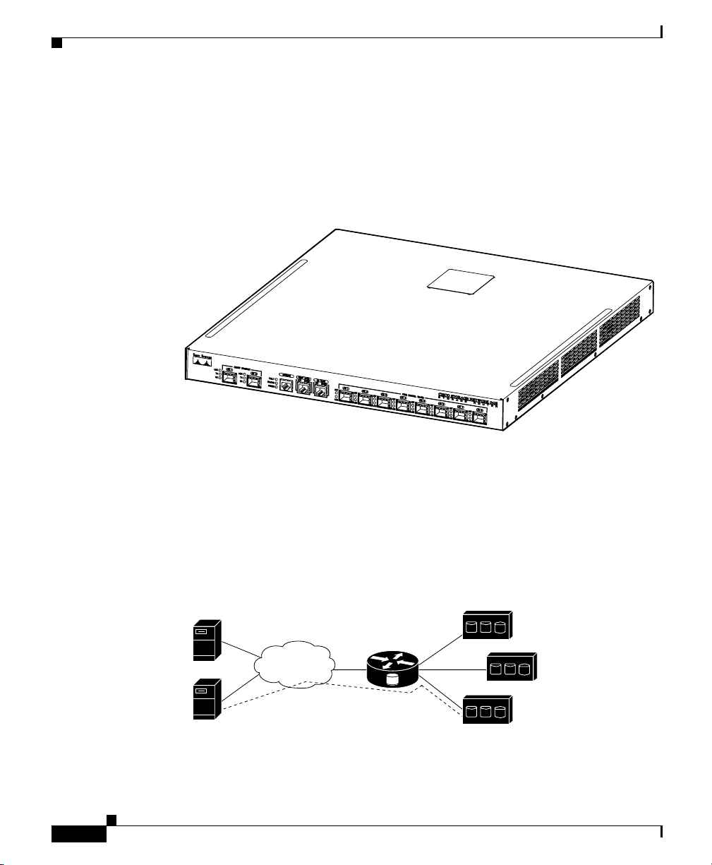
The SN 5428 Storage Router is a 1U rack-mountable chassis (see Figure 1-1) that
provides IP hosts with access to Fibre Channel storage through an IP network.
Figure 1-1 SN 5428 Storage Router Chassis
Chapter 1 Product Overview
73874
1-2
The storage router provides IP hosts with access to Fibre Channel storage as if the
IP hosts were directly attached to the storage. (See Figure 1-2.) For more
information about the types of storage access available with the SN 5428 Storage
Router, see the SN 5428 Storage Router Software Configuration Guide and other
related documentation.
Figure 1-2 IP Hosts Accessing Storage Through the SN 5428 Storage Router
IP hosts
Cisco SN 5428
IP
An IP host accesses
FC storage as if it
were directly attached
to the storage.
Cisco SN 5428 Storage Router Hardware Installation Guide
FC storage
77073
OL-4796-01
Page 19
Chapter 1 Product Overview
Port Descriptions
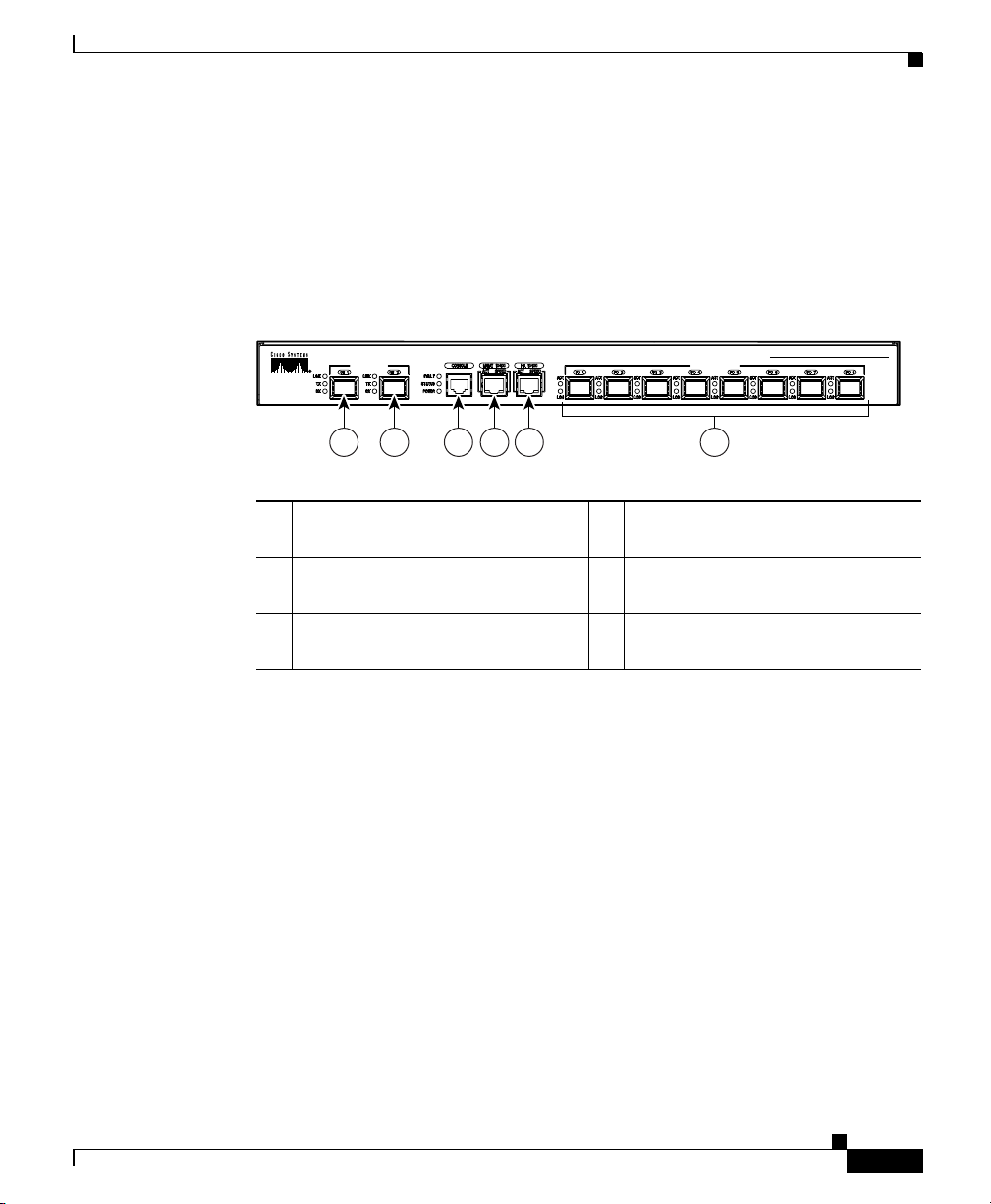
The SN 5428 Storage Router provides two 1-Gigabit Ethernet ports, a console
port, a 10/100 Ethernet management port, a 10/100 Ethernet high availability
(HA) port, and eight 1-Gigabit/2-Gigabit Fibre Channel ports. (See Figure 1-3.)
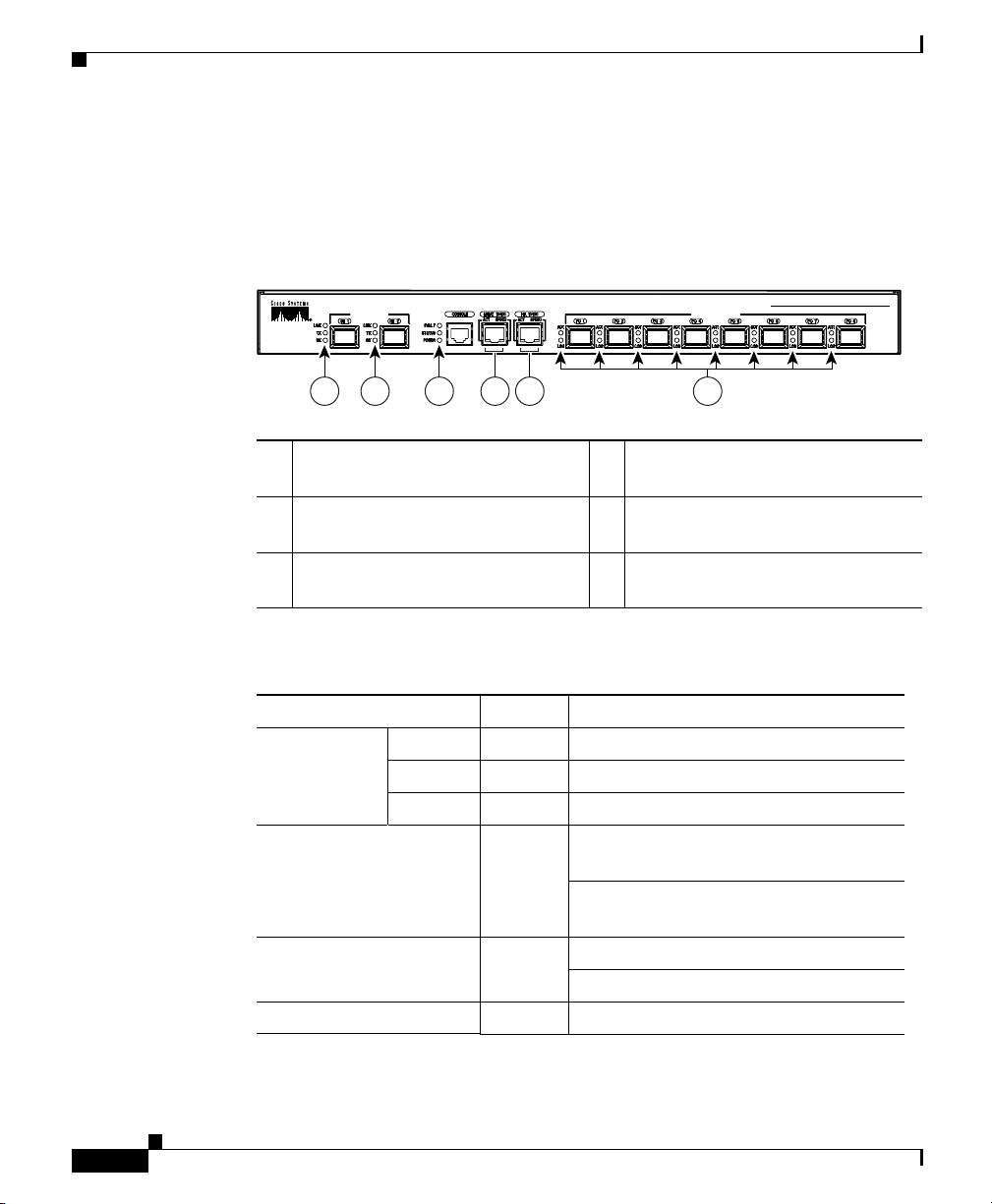
Figure 1-3 SN 5428 Storage Router Ports
1 2 3 4 5 6
1 Gigabit Ethernet port, GE 1 4 10/100 Ethernet management port,
2 Gigabit Ethernet port, GE 2 5 10/100 Ethernet high availability
3 Console port, CONSOLE 6 Fibre Channel ports, FC 1 through
GIGABIT ETHERNET
Port Descriptions
CISCO STORAGE NETWORK 5428
FIBRE CHANNEL 1Gb/2gB
MGMT 10/100
(HA) port, HA 10/100
FC 8 (from left to right)
STORAGE ROUTER
73982
OL-4796-01
The following sections described the ports:
• Gigabit Ethernet Ports, page 1-4
• Console Port, page 1-4
• 10/100 Ethernet Management Port, page 1-4
• 10/100 Ethernet HA Port, page 1-4
• Fibre Channel Ports, page 1-5
Cisco SN 5428 Storage Router Hardware Installation Guide
1-3
Page 20

Port Descriptions
Gigabit Ethernet Ports
The Gigabit Ethernet ports are labeled GE 1 and GE 2. (See Figure 1-3.) Each
port provides a 1-Gigabit Ethernet interface for connecting to IP hosts that require
IP access to storage. Each port uses a small form-factor pluggable (SFP) module
for connection to the port’s physical medium. See Appendix B, “Cable and Port
Pinouts” for SFP module specifications. Each Gigabit Ethernet port has LEDs
indicating its status, as described in the “Front-Panel LEDs” section on page 1-5.
Console Port
The console port is labeled CONSOLE. (See Figure 1-3.) It is an EIA/TIA-232
interface for connecting to the serial port of a PC running terminal emulation
software. Using the console port you can manage the storage router with the
SN 5428 Storage Router command-line interface (CLI). The console port uses an
8-pin RJ-45 receptacle. It has no LEDs.
Chapter 1 Product Overview
10/100 Ethernet Management Port
The 10/100 Ethernet management port is labeled MGMT 10/100. (See
Figure 1-3.) It is a 10BaseT/10 0Bas eT Ethernet interface for connecting to a
management network. Through a management network you can manage the
storage router using the CLI, the web-based GUI, or SNMP. The 10/100 Ethernet
management port uses an 8-pin RJ-45 receptacle and has LEDs indicating its
status, as described in the “Front-Panel LEDs” section on page 1-5.
10/100 Ethernet HA Port
The 10/100 Ethernet high availability (HA) port is labeled HA 10/100. (See
Figure 1-3.) It is a 10Base T/100Ba seT Ethernet interface for connecting to an HA
network. The port allows the SN 5428 to function in a multiple-node cluster with
other SN 5428 Storage Routers to provide fault-tolerant operation.The 10/100
Ethernet HA port uses an 8-pin RJ-45 receptacle and has LEDs indicating its
status, as described in the “Front-Panel LEDs” section on page 1-5.
Cisco SN 5428 Storage Router Hardware Installation Guide
1-4
OL-4796-01
Page 21

Chapter 1 Product Overview
Fibre Channel Ports
The Fibre Channel ports are labeled FC 1 through FC 8. (See Figure 1-3.) Each
port provides a 1-Gigabit/2-Gigabit autosensing Fibre Channel interface for
connecting to storage systems, Fibre Channel switches, Fibre Channel hosts, or
other Cisco storage networking products. Each Fibre Channel port can be
configured as one of the following port types: G_Port, GL_Port, F_Port, FL_Port,
or TL_Port. Each port uses a small form-factor pluggable (SFP) module for
connection to the port’s physical medium. See Appendix B, “Cable and Port
Pinouts” for SFP module specifications. Each Fibre Channel port has LEDs
indicating its status, as described in the “Front-Panel LEDs” section.
The storage router contains two internal Fibre Channel interfaces to allow access
between the GE ports and the Fibre Channel ports, FC 1 through FC 8. These two
internal Fibre Channel interfaces are named fci1 and fci2. As Fibre Channel
initiators, these interfaces are assigned World Wide Port Numbers (WWPN);
therefore, fci1 is also referred to as initiator WWPN1 and fci2 is also referred to
as initiator WWPN2. There are no hardware installation tasks for these interfaces;
however, it is important to be aware of this internal architecture and the WWPNs
for some software configuration tasks that required these port WWPNs (i.e.
zoning).
Front-Panel LEDs
Front-Panel LEDs
The front-panel LEDs provide status indications about the SN 5428 chassis and
its ports. (See Figure 1-4.)
Each Gigabit Ethernet port, GE 1 and GE 2, has three LEDs, labeled LINK, TX,
and RX. The LEDs are located to the left of each Gigabit Ethernet port.
The FAULT, STATUS, and POWER LEDs indicate the overall status of the
SN 5428 Storage Router. The LEDs are located to the left of the CONSOLE port.
The 10/100 Ethernet management port, MGMT 10/100, has two LEDs, labeled
ACT and SPEED. The ACT LED is located at the left-bottom corner of the port;
the SPEED LED is located at the right-bottom corner of the port.
The 10/100 Ethernet HA port, HA 10/100, has two LEDs, labeled ACT and
SPEED. The ACT LED is located at the left-bottom corner of the port; the SPEED
LED is located at the right-bottom corner of the port.
OL-4796-01
Cisco SN 5428 Storage Router Hardware Installation Guide
1-5
Page 22
Front-Panel LEDs
Chapter 1 Product Overview
Each Fibre Channel port, FC 1 through FC 8, has two LEDs, labeled ACT and
LOG. The LEDs are located to the left of each Fibre Channel port.
Table 1-1 describes the LED indications.
Figure 1-4 SN 5428 Front-Panel LEDs
CISCO STORAGE NETWORK 5428
GIGABIT ETHERNET
FIBRE CHANNEL 1Gb/2gB
1 2 3 4 5 6
1 Gigabit Ethernet port, GE 1 4 10/100 Ethernet management port,
MGMT 10/100
2 Gigabit Ethernet port, GE 2 5 10/100 Ethernet HA port,
HA 10/100
3 FAULT, STATUS, and POWER 6 Fibre Channel ports, FC 1 through
FC 8
STORAGE ROUTER
73983
1-6
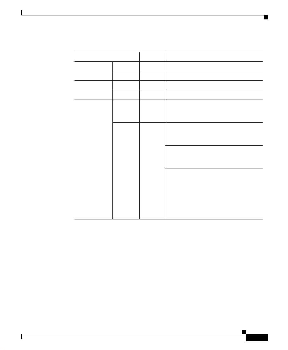
Table 1-1 LED Indication Descriptions
LED Color Description (when LED is on)
GE 1 and
GE 2 LEDs
LINK Green Port is operational.
TX Green Packets are being transmitted.
RX Green Packets are being received.
FAULT Red On if error condition in entire storage
STATUS Green On after successful boot up.
POWER Green Power is on.
Cisco SN 5428 Storage Router Hardware Installation Guide
router.
Flashing if error condition in a storage
router component.
Flashing during boot up.
OL-4796-01
Page 23
Chapter 1 Product Overview
Table 1-1 LED Indication Descriptions (continued)
LED Color Description (when LED is on)
MGMT
10/100 LEDs
HA 10/100
LEDs
FC 1 through
FC 8 LEDs
Front-Panel LEDs
ACT Green (Left) Link is active.
SPEED Yellow (Right) Port speed is 100 Mbps.
ACT Green (Left) Link is active.
SPEED Yellow (Right) Port speed is 100 Mbps.
ACT
(Activity
LED)
LOG
(LoggedIn LED)
Yellow Frames are being transmitted or
received.
Green On (continuously) indicates that the
port is properly connected and able to
communicate with its attached devices.
Flashing once per second indicates that
the port connection is in the process of
logging in.
Flashing twice per second indicates
that the port connection is broken or an
error condition exists with the port. For
troubleshooting information refer to
“Troubleshooting a Connection to a
Fibre Channel Port” section on
page 3-6.
OL-4796-01
Cisco SN 5428 Storage Router Hardware Installation Guide
1-7
Page 24

Fan Assembly
Fan Assembly
The fan assembly provides cooling for the internal chassis components. The
SN 5428 chassis contains four exhaust fans that are located on the left side of the
chassis. The fans draw in air from the right side and exhaust air from the left side.
(See Figure 1-5.)
Figure 1-5 Chassis Airflow
Chapter 1 Product Overview
1-8
73984
Cisco SN 5428 Storage Router Hardware Installation Guide
OL-4796-01
Page 25

Chapter 1 Product Overview
Power Supply
The SN 5428 Storage Router has an internal power supply that monitors its
temperature and output voltages. The power supply automatically senses and
adjusts to either of these input voltages: 115 VAC/60 Hz or 230 VAC/50 Hz.
If conditions reach critical thresholds, the power supply will shut down to avoid
damage from excessive heat or electrical current. The power supply connects to
site power through a power cord and the power connector on the rear panel. (See
Figure 1-6.) The power supply is powered on with a rocker switch that is next to
the power connector. The switch is labeled
Pressing
Figure 1-6 Rear Panel, Power Connector
O
switches power off.
Power Supply
I
and O. Pressing I switches power on.
OL-4796-01
Power connector
73985
Cisco SN 5428 Storage Router Hardware Installation Guide
1-9
Page 26

Power Supply
Chapter 1 Product Overview
1-10
Cisco SN 5428 Storage Router Hardware Installation Guide
OL-4796-01
Page 27

CHAPTER
2
Installing the SN 5428 Storage Router
This chapter describes how to prepare your site for installation, how to prepare
and install the SN 5428 Storage Router chassis, how to connect network and Fibre
Channel cables, how to connect power, and how to verify correct installation. For
first-time installations, perform the procedures in the following sections in the
order listed here:
• Read Safety Notices, page 2-2
• Site Planning, page 2-5
• Installing the SN 5428 Chassis, page 2-6
• Installing SFP Modules, page 2-11
• Connecting to Gigabit Ethernet and Fibre Channel Ports, page 2-20
• Connecting to the 10/100 Ethernet Management and HA Ports, page 2-23
OL-4796-01
Warning
• Connecting to the Console Port, page 2-24
• Connecting Power, page 2-25
• Verifying Installation, page 2-27
• Where to Go Next, page 2-29
Before you install, operate, or service the system, read the Site Preparation and
Safety Guide. This guide contains important safety information you should know
before working with the system. To see translated versions of the warning,
refer to the Regulatory Compliance and Safety document that accompanied the
device.
Cisco SN 5428 Storage Router Hardware Installation Guide
2-1
Page 28

Read Safety Notices
Read Safety Notices
Read the following safety notices before installing the SN 5428 Storage Router.
Chapter 2 Installing the SN 5428 Storage Router
Warning
Warning
Warning
Warning
Warning
Ultimate disposal of this product should be handled according to all national
laws and regulations. To see translated versions of the warning, refer to the
Regulatory Compliance and Safety document that accompanied the device.
The device is designed to work with TN power systems. To see translated
versions of the warning, refer to the Regulatory Compliance and Safety
document that accompanied the device.
Only trained and qualified personnel should be allowed to install or replace this
equipment. To see translated versions of the warning, refer to the Regulatory
Compliance and Safety document that accompanied the device.
Before working on a system that has an on/off switch, turn OFF the power and
unplug the power cord. To see translated versions of the warning, refer to the
Regulatory Compliance and Safety document that accompanied the device.
Do not touch the power supply when the power cord is connected. For systems
with a power switch, line voltages are present within the power supply even
when the power switch is off and the power cord is connected. For systems
without a power switch, line voltages are present within the power supply
when the power cord is connected. To see translated versions of the warning,
refer to the Regulatory Compliance and Safety document that accompanied the
device.
2-2
Cisco SN 5428 Storage Router Hardware Installation Guide
OL-4796-01
Page 29

Chapter 2 Installing the SN 5428 Storage Router
Read Safety Notices
Warning
Warning
Warning
Warning
The plug-socket combination must be accessible at all times because it serves
as the main disconnecting device. To see translated versions of the warning,
refer to the Regulatory Compliance and Safety document that accompanied the
device.
This product relies on the building’s installation for short-circuit (overcurrent)
protection. Ensure that a fuse or circuit breaker no larger than 120 VAC, 15A U.S.
(240 VAC, 10A international) is used on the phase conductors (all
current-carrying conductors). To see translated versions of the warning, refer
to the Regulatory Compliance and Safety document that accompanied the
device.
When installing the unit, the ground connection must always be made first and
disconnected last. To see translated versions of the warning, refer to the
Regulatory Compliance and Safety document that accompanied the device.
This equipment is intended to be grounded. Ensure that the host is connected to
earth ground during normal use. To see translated versions of the warning, refer
to the Regulatory Compliance and Safety document that accompanied the
device.
OL-4796-01
Warning
Warning
Never defeat the ground conductor or operate the equipment in the absence of
a suitably installed ground conductor. Contact the appropriate electrical
inspection authority or an electrician if you are uncertain that suitable
grounding is available. To see translated versions of the warning, refer to the
Regulatory Compliance and Safety document that accompanied the device.
During this procedure, wear grounding wrist straps to avoid ESD damage to the
card. Do not directly touch the backplane with your hand or any metal tool, or
you could shock yourself. To see translated versions of the warning, refer to the
Regulatory Compliance and Safety document that accompanied the device.
Cisco SN 5428 Storage Router Hardware Installation Guide
2-3
Page 30

Read Safety Notices
Chapter 2 Installing the SN 5428 Storage Router
Warning
Warning
Warning
Warning
The safety cover is an integral part of the product. Do not operate the unit
without the safety cover installed. Operating the unit without the cover in place
will invalidate the safety approvals and pose a risk of fire and electrical
hazards. To see translated versions of the warning, refer to the Regulatory
Compliance and Safety document that accompanied the device.
Blank faceplates and cover panels serve three important functions: they
prevent exposure to hazardous voltages and currents inside the chassis; they
contain electromagnetic interference (EMI) that might disrupt other equipment;
and they direct the flow of cooling air through the chassis. Do not operate the
system unless all cards, faceplates, front covers, and rear covers are in place.
To see translated versions of the warning, refer to the Regulatory Compliance
and Safety document that accompanied the device.
Before working on equipment that is connected to power lines, remove jewelry
(including rings, necklaces, and watches). Metal objects will heat up when
connected to power and ground and can cause serious burns or weld the metal
object to the terminals. To see translated versions of the warning, refer to the
Regulatory Compliance and Safety document that accompanied the device.
A voltage mismatch can cause equipment damage and may pose a fire hazard.
If the voltage indicated on the label is different from the power outlet voltage,
do not connect the chassis to that receptacle. To see translated versions of the
warning, refer to the Regulatory Compliance and Safety document that
accompanied the device.
2-4
Warning
To avoid electric shock, do not connect safety extra-low voltage (SELV) circuits
to telephone-network voltage (TNV) circuits. LAN ports contain SELV circuits,
and WAN ports contain TNV circuits. Some LAN and WAN ports both use RJ-45
connectors. Use caution when connecting cables. To see translated versions of
the warning, refer to the Regulatory Compliance and Safety document that
accompanied the device.
Cisco SN 5428 Storage Router Hardware Installation Guide
OL-4796-01
Page 31

Chapter 2 Installing the SN 5428 Storage Router
Site Planning
Warning
Warning
Class 1 laser product. To see translated versions of the warning, refer to the
Regulatory Compliance and Safety document that accompanied the device.
Because invisible laser radiation may be emitted from the aperture of the port
when no cable is connected, avoid exposure to laser radiation and do not stare
into open apertures. To see translated versions of the warning, refer to the
Regulatory Compliance and Safety document that accompanied the device.
Site Planning
Planning the proper location and layout of your SN 5428 Storage Router, your
equipment rack, or wiring closet is essential for successful storage router
operation. Equipment placed too close together or in an inadequately ventilated
area can cause system overtemperature conditions. In addition, poor equipment
placement can make system panels inaccessible and difficult to maintain.
To ensure normal operation and to avoid unnecessary maintenance, plan your site
configuration and prepare your site before installation.
Table A-1 on page A-1 lists the operating and nonoperating environmental site
requirements for the SN 5428 Storage Router. Within specified environmental
ranges the system can continue to operate; however, a measurement that
approaches the minimum or maximum of a range indicates a potential problem.
You can maintain normal operation by anticipating and correcting environmental
conditions before they exceed the maximum operating range.
OL-4796-01
Verify the site power for the type of device you are installing. Power requirements
are useful for planning the power distribution system needed to support the
storage router. Heat dissipation is an important consideration for sizing the
air-conditioning requirements for an installation. See Table A-1 on page A-1 for
power and heat ratings for the storage router.
Caution To prevent a loss of input power, verify that the total maximum load on the circuit
supplying power to the power supply is within the current ratings of the wiring
and breakers.
Cisco SN 5428 Storage Router Hardware Installation Guide
2-5
Page 32

Installing the SN 5428 Chassis
Installing the SN 5428 Chassis
You can install the SN 5428 chassis on a table or a shelf, or in an equipment rack.
The following sections describe the steps required to install the SN 5428 chassis:
• Installing on a Table or a Shelf, page 2-6
• Rack-Mounting the SN 5428 Storage Router, page 2-7
• Attaching the Optional Cable Guide, page 2-10
Before installing the storage router, read the Site Preparation and Safety Guide to
familiarize yourself with proper site and environmental conditions.
Installing on a Table or a Shelf
You can install the SN 5428 Storage Router chassis on a table or a shelf (or
another flat, secure surface).
If you are going to install the SN 5428 Storage Router in an equipment rack, skip
this section and proceed to the “Rack-Mounting the SN 5428 Storage Router”
section on page 2-7. To install the chassis on a table or a shelf, follow these steps:
Chapter 2 Installing the SN 5428 Storage Router
2-6
Step 1 Locate the four adhesive-backed rubber feet. They are in the accessory kit that is
shipped with the storage router.
Step 2 Peel the rubber feet from their backing and place the feet, adhesive-side down,
onto the four round recessed areas on the bottom of the chassis.
Step 3 Place the storage router on a table or a shelf near an AC power source.
Cisco SN 5428 Storage Router Hardware Installation Guide
OL-4796-01
Page 33

Chapter 2 Installing the SN 5428 Storage Router
Rack-Mounting the SN 5428 Storage Router
You can rack-mount the SN 5428 Storage Router chassis in a 19-inch equipment
rack with the front panel forward.
The accessory kit that is shipped with your storage router contains two
L-brackets, six L-bracket screws, a cable guide (with mounting screw), and two
sets of rack-post screws. One set of rack-post screws consists of four 10-32 3/4”
screws; the other set consists of four 12-24 3/4” screws.
Note If your mounting-post holes cannot accommodate the rack-post screws shipped
with your storage router, you will need to supply other screws (and clips if
necessary) suitable for your equipment rack.
You need the following tools to install the storage router in a rack:
• Phillips screwdriver suitable for L-bracket screws and cable-guide screw
• Phillips screwdriver suitable for the rack-post screws
• Tape measure
Installing the SN 5428 Chassis
OL-4796-01
To install the storage router in a rack, follow these steps:
Step 1 Prepare for installation as follows:
a. Place the storage router on the floor or on a sturdy table as close as possible
to the rack. Leave enough clearance so that you can move around the storage
router.
b. Use a tape measure to measure the depth of the rack. Measure from the
outside of the front mounting posts to the outside of the rear mounting strip.
The depth must be at least 19 inches (48.26 cm) but not more than 32 inches
(81.3 cm).
c. Measure the space between the inner edges of the left-front and right-front
mounting posts to ensure that the space is 17.75 inches (45.72 cm) wide.
Step 2 Remove the front screw from each side of the chassis. (See Figure 2-1.) You may
discard the screws.
Cisco SN 5428 Storage Router Hardware Installation Guide
2-7
Page 34

Installing the SN 5428 Chassis
Figure 2-1 Removing the Front Screws from the Sides
Step 3 Attach the left and right L-brackets using the screws supplied with the brackets in
the accessory kit. (See Figure 2-2.)
Figure 2-2 Attaching the L-Brackets
Chapter 2 Installing the SN 5428 Storage Router
73988
2-8
73989
Step 4 Install the storage router in the rack as follows:
a. Insert the rear of the storage router between the mounting posts.
b. Align the mounting holes in the L-brackets with the mounting holes in the
equipment rack.
Cisco SN 5428 Storage Router Hardware Installation Guide
OL-4796-01
Page 35

Chapter 2 Installing the SN 5428 Storage Router
c. Secure the storage router by screwing four (two on each side) screws through
the elongated holes in the L-brackets and into the threaded holes in the
mounting posts. (See Figure 2-3.)
Figure 2-3 Installing the Chassis in the Rack
Installing the SN 5428 Chassis
73990
OL-4796-01
Cisco SN 5428 Storage Router Hardware Installation Guide
2-9
Page 36

Installing the SN 5428 Chassis
Attaching the Optional Cable Guide
A cable guide is included in the accessory kit that is shipped with the SN 5428
Storage Router. If the storage router is installed in a rack, you can attach the cable
guide to either the left or right L-bracket, using the supplied black screw. (See
Figure 2-4.) Attaching the cable guide will prevent the cables from obscuring the
front panel of the storage router and the other devices in the rack.
Figure 2-4 Attaching the Cable Guide
Chapter 2 Installing the SN 5428 Storage Router
2-10
Cable guide screw
77065
Cisco SN 5428 Storage Router Hardware Installation Guide
OL-4796-01
Page 37

Chapter 2 Installing the SN 5428 Storage Router
Installing SFP Modules
Before you install or remove an SFP (small form-factor pluggable) module, read
the installation information in this section. For connecting to SFP modules in the
Gigabit Ethernet ports and the Fibre Channel ports, read the instructions in the
“Connecting to Gigabit Ethernet and Fibre Channel Ports” section on page 2-20.
Note Because of interoperability issues, Cisco does not support SFPs purchased from
third-party vendors. See Appendix B, “Cable and Port Pinouts” for SFP port
specifications.
Note When fiber-optic cable plugs and SFP module receptacles are disconnected from
each other, place dust covers on them.
Installing SFP Modules
OL-4796-01
Warning
Because invisible radiation may be emitted from the aperture of the port when
no fiber cable is connected, avoid exposure to radiation and do not stare into
open apertures. To see translated versions of the warning, refer to the
Regulatory Compliance and Safety document that accompanied the device.
The Gigabit Ethernet ports use fiber-optic SFP modules with either MT-RJ
connectors (see Figure 2-5) or LC connectors (see Figure 2-6). The Fibre Channel
ports use fiber-optic SFP modules with LC connectors (see Figure 2-6). See
Table 2-1 on page 2-13 to determine what types of SFP modules you can install
in the Gigabit Ethernet and Fibre Channel ports. See Appendix B, “Cable and Port
Pinouts” for SFP module specifications.
Cisco SN 5428 Storage Router Hardware Installation Guide
2-11
Page 38

Installing SFP Modules
Caution Protect your fiber-optic SFP modules by inserting clean dust covers into the SFPs
Chapter 2 Installing the SN 5428 Storage Router
Figure 2-5 MT-RJ Fiber-Optic Connector and SFP Module
MT-RJ plug
SFP module
77927
after the cables are extracted from them. Be sure to clean the optic surfaces of the
fiber cables before you plug them back into the optical bores of another SFP
module. Avoid getting dust and other contaminants into the optical bores of your
SFP modules: The optics will not work correctly when obstructed with dust.
2-12
Cisco SN 5428 Storage Router Hardware Installation Guide
OL-4796-01
Page 39

Chapter 2 Installing the SN 5428 Storage Router
Installing SFP Modules
Figure 2-6 LC Connector and Fiber-Optic SFP Module
LC plug
SFP module
77926
Table 2-1 Types of SFP Modules for Gigabit Ethernet and Fibre Channel Ports
SFP Product Number Connector Type Port Usage
SN-SFP-GEMM-MTRJ MT-RJ Gigabit Ethernet only This module can be used in any
combination with the
SN-SFP-FCGEMM-LC module.
SN-SFP-FCMM-LC LC Fibre Channel only This module can be used in any
combination with the
SN-SFP-FCGEMM-LC module.
SN-SFP-FCGEMM-LC LC Gigabit Ethernet or
Fibre Channel
For Gigabit Ethernet ports, this
module can be used in any
combination with the
SN-SFP-GEMM-MTRJ module.
For Fibre Channel ports, this
module can be used in any
combination with the
SN-SFP-FCMM-LC module.
OL-4796-01
Cisco SN 5428 Storage Router Hardware Installation Guide
2-13
Page 40

Installing SFP Modules
The SFP modules have three different types of latching devices used to secure and
detach the SFP module from a port. The three types of SFP modules are described
in the following sections:
• Mylar Tab SFP Modules, page 2-14
• Actuator/Button SFP Modules, page 2-16
• Bale Clasp SFP Modules, page 2-18
Mylar Tab SFP Modules
The Mylar tab SFP module (see Figure 2-7) has a tab that you must pull in order
to remove the module from a port.
Figure 2-7 Mylar Tab SFP Module
Chapter 2 Installing the SN 5428 Storage Router
2-14
63065
To insert the Mylar tab SFP module into a port, line up the SFP module with the
port, and slide it into place (see Figure 2-8).
Cisco SN 5428 Storage Router Hardware Installation Guide
OL-4796-01
Page 41

Chapter 2 Installing the SN 5428 Storage Router
Figure 2-8 Inserting a Mylar Tab SFP Module
Caution When pulling the tab to remove the SFP module, be sure to pull in a straight
outward motion so you remove the SFP module from the port in a parallel
direction. Do not twist or pull the tab because you may disconnect it from the SFP
module.
Installing SFP Modules
73992
OL-4796-01
To remove the SFP module from the port, pull the tab gently in a slightly
downward direction until it disengages from the port, and then pull the SFP
module out (see Figure 2-9).
Figure 2-9 Removing a Mylar Tab SFP Module
73993
Cisco SN 5428 Storage Router Hardware Installation Guide
2-15
Page 42

Installing SFP Modules
Actuator/Button SFP Modules
The actuator/button SFP module (see Figure 2-10) has a button that you must
push in order to remove the SFP module from a port.
Figure 2-10 Actuator/Button SFP Module
To insert the actuator/button SFP module into a port, line up the SFP module with
the port and slide it in until the actuator/button clicks into place (see Figure 2-11).
Be sure not to press the actuator/button as you insert the SFP module because you
might inadvertently disengage the SFP module from the port.
Chapter 2 Installing the SN 5428 Storage Router
63066
2-16
Figure 2-11 Inserting an Actuator/Button SFP Module
73994
To remove an actuator/button SFP module from a port, perform the following
steps:
Step 1 Gently press the actuator/button on the front of the SFP module until it clicks and
the latch mechanism activates, releasing the SFP module from the port (see
Figure 2-12).
Cisco SN 5428 Storage Router Hardware Installation Guide
OL-4796-01
Page 43

Chapter 2 Installing the SN 5428 Storage Router
Step 2 Grasp the actuator/button between your thumb and index finger and carefully pull
the SFP module from the port.
Figure 2-12 Removing an Actuator/Button SFP Module from a Port
Installing SFP Modules
OL-4796-01
STATUS
73995
Cisco SN 5428 Storage Router Hardware Installation Guide
2-17
Page 44

Installing SFP Modules
Bale Clasp SFP Modules
The bale clasp SFP module (see Figure 2-13) has a bale clasp that you use to
secure the SFP module in a port.
Figure 2-13 Bale Clasp SFP Module
To insert a bale clasp SFP module into a port, perform the following steps:
Step 1 Close the bale clasp before inserting the SFP module.
Step 2 Line up the SFP module with the port and slide it into the port (see Figure 2-14).
Chapter 2 Installing the SN 5428 Storage Router
63067
2-18
Figure 2-14 Inserting a Bale Clasp SFP Module into a Port
73996
Cisco SN 5428 Storage Router Hardware Installation Guide
OL-4796-01
Page 45

Chapter 2 Installing the SN 5428 Storage Router
To remove a bale clasp SFP module from a port, perform the following steps:
Step 1 Open the bale clasp on the SFP module with your index finger in a downward
direction as shown in Figure 2-15. If the bale clasp is obstructed and you cannot
use your index finger to open it, use a small, flat-blade screwdriver or other long,
narrow instrument to open the bale clasp as shown in Figure 2-16.
Step 2 Grasp the SFP module between your thumb and index finger and carefully remove
it from the port as shown in Figure 2-15.
Figure 2-15 Removing a Bale Clasp SFP Module with Your Index Finger
Installing SFP Modules
OL-4796-01
73997
Cisco SN 5428 Storage Router Hardware Installation Guide
2-19
Page 46

Connecting to Gigabit Ethernet and Fibre Channel Ports
Figure 2-16 Removing a Bale Clasp SFP Module with a Flat-Blade Screwdriver
Chapter 2 Installing the SN 5428 Storage Router
73998
Connecting to Gigabit Ethernet and Fibre Channel
Ports
The Gigabit Ethernet ports, GE 1 and GE 2, use MT-RJ-type or LC-type
fiber-optic SFP modules and cables. The Fibre Channel ports, FC 1 though FC 8,
use LC-type fiber-optic SFP modules and cables. When you are connecting a
cable to a fiber-optic SFP module, make sure that you firmly press the cable plug
into the socket. The upper edge of the plug must snap into the upper front edge of
the socket. You should hear the plug click when it is locked into the socket. To
make sure that the plug is locked into the socket, gently pull on it.
To disconnect a plug from a socket, press the trigger on top of the plug, releasing
the latch. You should hear a click, which indicates that the latch has released.
Carefully pull the plug out of the socket.
Cisco SN 5428 Storage Router Hardware Installation Guide
2-20
OL-4796-01
Page 47

Chapter 2 Installing the SN 5428 Storage Router
Note When you disconnect the fiber-optic cable from the module, grip the body of the
connector. Do not grip the connector jacket-sleeve. Gripping the sleeve can, over
time, compromise the integrity of the fiber-optic cable termination in the
connector.
Dirt or skin oils may have accumulated on an MT-RJ plug faceplate (around the
optical-fiber openings), which can generate significant attenuation and reduce the
optical power levels below threshold levels so that a link cannot be made. To
clean an MT-RJ plug faceplate, follow this procedure:
Step 1 Using a lint-free tissue soaked in 99 percent pure isopropyl alcohol, gently wipe
the faceplate.
Step 2 Remove any residual dust from the faceplate with compressed air before installing
the cable.
Connecting to Gigabit Ethernet and Fibre Channel Ports
OL-4796-01
Note When fiber-optic cable plugs and SFP module receptacles are disconnected from
each other, place dust covers on them.
The following sections describe how to connect cables to the Gigabit Ethernet and
Fibre Channel ports:
• Connecting to a Gigabit Ethernet Port, page 2-22
• Connecting to a Fibre Channel Port, page 2-22
Cisco SN 5428 Storage Router Hardware Installation Guide
2-21
Page 48

Connecting to Gigabit Ethernet and Fibre Channel Ports
Connecting to a Gigabit Ethernet Port
To connect a cable to a Gigabit Ethernet port, follow these steps:
Step 1 Remove the dust cover from the SFP module in the Gigabit Ethernet port; store
the dust cover for future use.
Step 2 Remove the dust cover (or covers) from the plug on the cable; store the cover (or
covers) for future use. Insert the cable plug into the Gigabit Ethernet SFP module.
Step 3 Connect the other end of the cable to the external end system, switch, or router.
Connecting to a Fibre Channel Port
Caution If an SN 5428 Fibre Channel port is going to be connected to a zoned fabric, do
not connect the port until you have completed the SN 5428 hardware installation
and have confirmed that the SN 5428 Domain ID has been configured. After the
SN 5428 has been installed and after the SN 5428 Domain ID has been
configured, you can then connect Fibre Channel ports to zoned fabric according
to the procedures in this section. Then, verify the operation of the ports according
to the procedures in the “Verify That Fibre Channel Connections Are
Operational” section on page 2-28. For information about configuring the
Domain ID, see the Cisco SN 5428 Storage Router Software Configuration Guide.
Chapter 2 Installing the SN 5428 Storage Router
2-22
To connect a cable to a Fibre Channel port, follow these steps:
Step 1 Remove the dust cover from the SFP module in the Fibre Channel SFP port; store
the dust cover for future use.
Step 2 Remove the dust covers from the cable plug on the fiber-optic cable; store the dust
covers for future use. Insert the cable plug into the Fibre Channel SFP module.
Step 3 Connect the other end of the cable to a Fibre Channel port of another system (for
example, a storage system, switch, host, or another SN 5428 Storage Router.)
Cisco SN 5428 Storage Router Hardware Installation Guide
OL-4796-01
Page 49

Chapter 2 Installing the SN 5428 Storage Router
Connecting to the 10/100 Ethernet Management and HA Ports
Connecting to the 10/100 Ethernet Management and
HA Ports
To connect to the 10/100 management and HA ports, follow these steps:
Step 1 Use modular, RJ-45, straight-through UTP cables to connect the 10/100
management and HA ports to end systems. Use modular, RJ-45 cross-connect
cables to connect to external switches and routers.
Step 2 Connect the appropriate modular cables to the 10/100 management and HA ports.
(See Figure 2-17.)
Figure 2-17 Connecting to the 10/100 Management and HA Ports
OL-4796-01
Step 3
Cable
To management
network equipment
Connect the other end of the cable to the external end system, switch, or router.
Cisco SN 5428 Storage Router Hardware Installation Guide
To HA network
equipment
73999
2-23
Page 50

Connecting to the Console Port
Connecting to the Console Port
Connect a PC serial port to the console port for local administrative access to the
SN 5428 Storage Router. The PC must support VT100 terminal emulation. The
terminal-emulation software—frequently a PC application such as
HyperTerminal or Procomm Plus—makes communication between the storage
router and your PC possible during setup and configuration.
Perform the following steps to connect to the console port:
Step 1 Configure the PC terminal emulation program to match these console port default
characteristics:
Bits Per Second 9600
Data Bits 8
Parity None
Stop Bits 1
Flow Control None
Chapter 2 Installing the SN 5428 Storage Router
2-24
Step 2 Connect the supplied RJ-45-to-DB-9 female adapter to the PC serial port.
Step 3 Connect one end of the supplied console cable (a rollover RJ-45-to-RJ-45 cable)
to the console port. Connect the other end to the RJ-45-to-DB-9 adapter at the PC
serial port. (See Figure 2-18.)
Cisco SN 5428 Storage Router Hardware Installation Guide
OL-4796-01
Page 51

Chapter 2 Installing the SN 5428 Storage Router
Figure 2-18 Connecting the Console Cable
Connecting Power
To P C
serial port
RJ-45/DB-9
adapter
Connecting Power
The SN 5428 Storage Router can be connected to either of two power sources:
115-120 VAC/60 Hz or 230-240 VAC/50 Hz. The power supply automatically
senses the source and adjusts to either source.
To connect power to the storage router, follow these steps:
Step 1 Ensure that all site power and grounding requirements described in the Site
Preparation and Safety Guide have been met before connecting the chassis to a
power source.
Step 2 Make sure the power switch is set to off. (See Figure 2-19.)
Rollover cable
74000
OL-4796-01
Cisco SN 5428 Storage Router Hardware Installation Guide
2-25
Page 52

Connecting Power
Step 3 Plug the power cord into the power receptacle located on the rear panel on the
Chapter 2 Installing the SN 5428 Storage Router
Figure 2-19 Power Set to Off
I
O
Power switch
set to off
chassis. (See Figure 2-20.)
Figure 2-20 Connecting a Power Cord to the SN 5428 Power Connector
77001
2-26
0
Step 4
Cisco SN 5428 Storage Router Hardware Installation Guide
Connect the other end of the power cord to the power source for the storage router.
77002
OL-4796-01
Page 53

Chapter 2 Installing the SN 5428 Storage Router
Verifying Installation
Verifying installation of the SN 5428 Storage Router consists of making sure that
it starts up properly and that the network and Fibre Channel connections are
operational.
Caution Fibre Channel ports should not be connected to zoned fabric until the SN 5428
Domain ID has been configured. See the “Connecting to a Fibre Channel Port”
section on page 2-22. For information about configuring the Domain ID, see the
Cisco SN 5428 Storage Router Software Configuration Guide.
Verifying Start-up Operations
To verify that the storage router starts up properly, perform the following steps:
Step 1 At the rear of the storage router, press the power switch to the on position.
Verifying Installation
OL-4796-01
Step 2 At the front of the storage router, observe the POWER LED to make sure power
is on. Make sure that the FAULT LED is off.
Step 3 Listen and check for air flow to make sure the fan assembly is operating.
Step 4 Observe console output to make sure that the storage router software is booting
properly. The boot process may last for three to five minutes and will display boot
information and a banner. A successful boot-up is indicated by a CLI prompt for
user input.
Step 5 If any of these conditions are not met, reference Chapter 3, “Troubleshooting,” to
isolate and, if possible, resolve the problem.
Cisco SN 5428 Storage Router Hardware Installation Guide
2-27
Page 54

Chapter 2 Installing the SN 5428 Storage Router
Verifying Installation
Verify That Network Connections Are Operational
Verifying the network connections consists of making sure that the following
ports are operational: Gigabit Ethernet, 10/100 Ethernet management, and 10/100
HA.
To verify that the network connections are operational, perform the following
steps:
Step 1 Verify the Gigabit Ethernet port connections by checking the port link status
LED. See Table 1-1 on page 1-6 for LED indication descriptions.
Step 2 Verify the 10/100 Ethernet management port connection by checking the port link
status LED. See Table 1-1 on page 1-6 for LED indication descriptions.
Step 3 Verify the 10/100 HA port connection by checking the port link status LED. See
Table 1-1 on page 1-6 for LED indication descriptions.
Step 4 If any of these conditions are not met, reference Chapter 3, “Troubleshooting,” to
isolate and, if possible, resolve the problem.
Verify That Fibre Channel Connections Are Operational
To verify that the connections are operational, perform the following steps:
Step 1 Verify Fibre Channel port connections by checking Fibre Channel LOG LEDs.
See Table 1-1 on page 1-6 for LED indication descriptions.
Step 2 If the LOG LEDs for connected ports are flashing, reference Chapter 3,
“Troubleshooting,” to isolate and, if possible, resolve the problem.
Cisco SN 5428 Storage Router Hardware Installation Guide
2-28
OL-4796-01
Page 55

Chapter 2 Installing the SN 5428 Storage Router
Where to Go Next
Once you have verified that the SN 5428 Storage Router hardware is properly
installed, it is ready for software configuration. To configure the software, refer
to the SN 5428 Storage Router Software Configuration Guide.
Where to Go Next
OL-4796-01
Cisco SN 5428 Storage Router Hardware Installation Guide
2-29
Page 56

Where to Go Next
Chapter 2 Installing the SN 5428 Storage Router
2-30
Cisco SN 5428 Storage Router Hardware Installation Guide
OL-4796-01
Page 57

CHAPTER
Troubleshooting
This chapter provides troubleshooting procedures for problems encountered
during installation and consists of the following sections:
• Solving Problems at the Component Level, page 3-1
• Identifying Startup Problems, page 3-2
• Troubleshooting the Power Supply, page 3-3
• Troubleshooting a Network or Fibre Channel Port Connection, page 3-4
• Contacting Customer Service, page 3-7
Solving Problems at the Component Level
The key to success when troubleshooting the SN 5428 Storage Router is to isolate
the problem to a specific storage router component. The first step is to compare
what the SN 5428 Storage Router is doing to what it should be doing. Because a
startup problem is usually attributed to a single component, it is more efficient to
isolate the problem to a subsystem rather than troubleshoot each separate
component in the storage router.
3
OL-4796-01
The SN 5428 Storage Router chassis consists of the following subsystems:
• The power supply operates whenever system power is on (see the
“Troubleshooting the Power Supply” section on page 3-3).
Cisco SN 5428 Storage Router Hardware Installation Guide
3-1
Page 58

Identifying Startup Problems
• The chassis fan assembly operates when the system power is on. The fan may
continue to operate even when the power supply shuts down the SN 5428
Storage Router because of an overtemperature or overvoltage condition
(although it does shut down for a power supply shutdown).
The following are simple checks you can make to determine if there is a fan
problem:
–
Listen to the fan assembly to determine if it is operating.
–
Check for any obstructions restricting airflow through the storage router.
If you determine that the fan assembly is not operating properly, contact a
customer service representative.
Identifying Startup Problems
Observe the operation of the SN 5428 Storage Router and its front-panel LEDs to
determine startup problems. LEDs indicate storage router states in the startup
sequence. By checking the LEDs, you can determine when and where the storage
router failed in the startup sequence.
Chapter 3 Troubleshooting
3-2
Perform the following steps when you power up the SN 5428 Storage Router:
Step 1 Listen for the chassis fan assembly operation. If it does not operate, see the
“Troubleshooting the Power Supply” section on page 3-3. If you determine that
the power supply is functioning normally and that the fan assembly is faulty,
contact a customer service representative. If the fan assembly does not function
properly at initial startup (there are no installation adjustments that you can
make), contact a customer service representative.
Step 2 Check the POWER LED on the front panel. The POWER LED turns on
immediately when power is on. The LED remains on during normal SN 5428
Storage Router operation. If the LED is not on, see the “Troubleshooting the
Power Supply” section on page 3-3.
Step 3 Check the STATUS and FAULT LEDs on the front panel. See the “Front-Panel
LEDs” section on page 1-5 for LED descriptions.
Cisco SN 5428 Storage Router Hardware Installation Guide
OL-4796-01
Page 59

Chapter 3 Troubleshooting
Step 4 Check the network and Fibre Channel port LEDs on the front panel. See the
“Front-Panel LEDs” section on page 1-5 for LED descriptions. If a network or
Fibre Channel port LED indicates a problem with the port connection, see the
“Troubleshooting a Network or Fibre Channel Port Connection” section on
page 3-4.
Step 5 Verify that the PC terminal emulation program is set correctly and that the PC is
connected properly to the console port. Also, verify at the PC terminal emulation
program display that the SN 5428 has started up properly (for example, a prompt
for starting a configuration wizard or a CLI prompt).
Step 6 Contact a customer service representative for instructions if a status LED
indicates a failure or if the PC connected to the console port indicates an
incomplete boot-up process.
Troubleshooting the Power Supply
To help isolate a power problem, follow these steps:
Troubleshooting the Power Supply
OL-4796-01
Step 1 Check the POWER LED.
• If the POWER LED is off, unplug the power cord, and then plug the power
cord back in.
• If the POWER LED remains off, check the AC source or the power cable for
problems.
Step 2 Connect the power cord to another power source if one is available.
• If the POWER LED comes on, the problem is the first power source.
• If the POWER LED is off after you connect the power supply to a new power
source, replace the power cord.
• If the POWER LED still fails to light when the storage router is connected to
a different power source with a new power cord, the power supply is probably
faulty.
Step 3 If you are unable to resolve the problem, contact a customer service representative
for instructions.
Cisco SN 5428 Storage Router Hardware Installation Guide
3-3
Page 60

Chapter 3 Troubleshooting
Troubleshooting a Network or Fibre Channel Port Connection
Troubleshooting a Network or Fibre Channel Port
Connection
If an LED on a network or Fibre Channel port indicates a problem, follow the
steps in the following sections to help isolate the problem:
• Troubleshooting a Connection to a Gigabit Ethernet Port, page 3-4
• Troubleshooting a Connection to a 10/100 Ethernet Management or 10/100
Ethernet HA Port, page 3-5
• Troubleshooting a Connection to a Fibre Channel Port, page 3-6
Troubleshooting a Connection to a Gigabit Ethernet Port
A bad connection to a Gigabit Ethernet (GE 1 or GE 2) port is indicated by the
LINK LED not being on. If the LINK LED is not on, follow these steps to help
isolate the problem:
3-4
Step 1 Check to make sure that the cable is connected properly and in good operating
condition.
• Disconnect and connect both ends of the cable. If the LINK LED turns on,
then the cable was not connected properly.
• If the LINK LED remains off, replace the cable. If the LINK LED turns on,
then the cable was defective.
• If the LINK LED remains off, the cable is most likely not the problem.
Continue to the next step.
Step 2 Check the external end system, switch, or router to which the port is connected.
• If the external end system, switch, or router is operating properly, continue to
the next step.
• If the external end system, switch, or router is not operating properly, then
correct the problem. If the LINK LED turns on, then the problem was with
the external end system, switch, or router.
• If the LINK LED remains off, continue to the next step.
Cisco SN 5428 Storage Router Hardware Installation Guide
OL-4796-01
Page 61

Chapter 3 Troubleshooting
Troubleshooting a Network or Fibre Channel Port Connection
Step 3 Replace the SFP module.
• If the LINK LED turns on, the problem was the SFP module.
• If the LINK LED remains off, contact a customer service representative for
instructions.
Troubleshooting a Connection to a 10/100 Ethernet Management or 10/100 Ethernet HA Port
A bad connection to the 10/100 Ethernet Management or the 10/100 Ethernet HA
port (MGMT 10/100 or HA 10/100) is indicated by the ACT LED not being on.
If the ACT LED is not on, follow these steps to help isolate the problem:
Step 1 Check to make sure that the cable is connected properly and in good operating
condition.
• Verify that the cable is the correct type of cable. (See Appendix B, “Cable
and Port Pinouts”.)
• Disconnect and connect both ends of the cable. If the ACT LED turns on, then
the cable was not connected properly.
OL-4796-01
• If the ACT LED remains off, replace the cable. If the ACT LED turns on, then
the cable was defective.
• If the ACT LED remains off, the cable is most likely not the problem.
Continue to the next step.
Step 2 Check the external end system, switch, or router to which the port is connected.
• If the external end system, switch, or router is operating properly, continue to
the next step.
• If the external end system, switch, or router is not operating properly, then
correct the problem. If the ACT LED turns on, then the problem was with the
external end system, switch, or router.
• If the ACT LED remains off, contact a customer service representative for
instructions.
Cisco SN 5428 Storage Router Hardware Installation Guide
3-5
Page 62

Chapter 3 Troubleshooting
Troubleshooting a Network or Fibre Channel Port Connection
Troubleshooting a Connection to a Fibre Channel Port
A bad connection to a Fibre Channel port (FC 1 through FC 8) is indicated by the
LOG LED flashing twice per second. If the LOG LED is flashing twice per
second, follow these steps to help isolate the problem:
Step 1 Make sure that the Domain ID of the SN 5428 is configured properly. For
information about configuring the Domain ID, see the Cisco SN 5428 Storage
Router Software Configuration Guide. If the Domain ID is configured properly,
continue to the next step.
Note When a connection problem is resolved, the LOG LED will turn on after
a brief logging-in period that is indicated by the LOG LED flashing once
per second.
Step 2 Check to make sure that the cable is connected properly and in good operating
condition.
• Disconnect and connect both ends of the cable. If the LOG LED turns on, then
the cable was not connected properly.
3-6
• If the LOG LED remains off, replace the cable. If the LOG LED turns on, then
the cable was defective.
• If the LOG LED remains off, the cable is most likely not the problem.
Continue to the next step.
Step 3 Check the device or switch to which the port is connected.
• If the device or switch is operating properly, continue to the next step.
• If the device or switch is not operating properly, then correct the problem. If
the LOG LED turns on, then the problem was with the device or switch.
• If the LOG LED remains off, continue to the next step.
Step 4 Replace the SFP module.
• If the LOG LED turns on, the problem was the SFP module.
• If the LOG LED remains off, contact a customer service representative for
instructions.
Cisco SN 5428 Storage Router Hardware Installation Guide
OL-4796-01
Page 63

Chapter 3 Troubleshooting
Contacting Customer Service
If you are unable to solve a startup problem after using the troubleshooting
suggestions in this chapter, contact a customer service representative for
assistance and further instructions. Before you call, have the following
information ready to help your service representative assist you as quickly as
possible:
• Date you received the SN 5428 Storage Router
• Chassis serial number (located on the upper-right label on the rear panel of
the chassis)
• Type of software and release number
• Maintenance agreement or warranty information
• Brief description of the problem
• Brief explanation of the steps you have taken to isolate and resolve the
problem
Contacting Customer Service
OL-4796-01
Cisco SN 5428 Storage Router Hardware Installation Guide
3-7
Page 64

Contacting Customer Service
Chapter 3 Troubleshooting
3-8
Cisco SN 5428 Storage Router Hardware Installation Guide
OL-4796-01
Page 65

APPENDIX
A
Technical Specifications
This appendix lists the technical specifications in Table A-1.
Table A-1 SN 5428 Storage Router Chassis Specifications
Environmental
Temperature, ambient operating 32 to 104°F (0 to 40°C)
Temperature, ambient nonoperating and storage –40 to 185°F (–40 to 85°C)
Humidity (RH), ambient (non-condensing)
operating
Humidity (RH), ambient (noncondensing)
nonoperating and storage
Altitude, operating and nonoperating –500 to 10,000 ft (–152.4 to 3,048 m)
Physical Characteristics
Dimensions (H x W x D) 1.75 x 17.44 x 19.17 in. (4.45 x 44.3 x 48.69 cm)
Weight 9.5 lb (4.3 kg)
AC Power
Power supply output 150W
System power dissipation 80 to 90W
AC current 2.0A maximum @ 100 to 240 VAC
AC frequency 50 to 60 Hz
Airflow Right side in, left side out
10 to 95 percent non-condensing
10 to 95 percent non-condensing
1
1 RU
in height
OL-4796-01
Cisco SN 5428 Storage Router Hardware Installation Guide
A-1
Page 66

Appendix A Technical Specifications
Table A-1 SN 5428 Storage Router Chassis Specifications (continued)
Power Supply
Fuse (F1) rating 5A, 250 VAC, time delay, not field-servicable
1. RU = rack unit
A-2
Cisco SN 5428 Storage Router Hardware Installation Guide
OL-4796-01
Page 67

APPENDIX
Cable and Port Pinouts
This appendix provides cabling and port pinout information for the SN 5428
Storage Router and includes the following sections:
• Gigabit and Fibre Channel Ports, page B-1
• 10/100 Ethernet Management and HA Ports, page B-3
• Console Port, page B-4
Gigabit and Fibre Channel Ports
Table B-1 lists the types of SFP modules and connectors used with the Gigabit
Ethernet and Fibre Channel ports in the SN 5428 Storage Router. For more
information about the SFP modules and connectors, see the standards for the SFP
modules and connectors.
B
Table B-1 SFP Modules and Connectors
Port Compliance Connector Fiber Type Cisco Product Number
Gigabit Ethernet,
GE 1 and GE 2
Fibre Channel,
FC 1 through
FC 8
OL-4796-01
1000Base-SX SW MMF DS-SFP-FCGE-SW
1000Base-LX LW SMF DS-SFP-FCGE-LW
FC-PI 100/200-M5-SN-I and
FC-PI 100/200-M6-SN-I
Cisco SN 5428 Storage Router Hardware Installation Guide
SW MMF DS-SFP-FCGE-SW
LW SMF DS-SFP-FCGE-LW
B-1
Page 68

Gigabit and Fibre Channel Ports
The DS-SFP-FCGE-SW is a short wave SFP that operates on ordinary multimode
fiber optic link spans of up to 500 meters in length for 1 Gbps Fibre Channel and
up to 300 meters in length for 2 Gbps Fibre Channel. This SFP is ideal for Fibre
Channel connectivity within an individual data center or department.
The DS-SFP-FCGE-LW operates on ordinary single-mode fiber optic link spans
of up to 10,000 meters in length. This SFP is ideal for Fibre Channel Connectivity
within a campus network or between data centers in close proximity.
Table B-2 lists the SFP port cabling specifications for the SFP modules and
connectors used in the SN 5428 Storage Router.
Table B-2 SFP Port Cabling Specifications
Appendix B Cable and Port Pinouts
Cisco Product Number
Wavelength
(nanometer)
Core Size
(micron) Baud Rate Cable Distance
DS-SFP-FCGE-SW 850 62.5
62.5
50.0
50.0
DS-SFP-FCGE-LW 1300 9.0
9.0
1.0625
2.125
1.0625
2.125
1.0625
2.125
300 m
150 m
500 m
300 m
10 km
10 km
B-2
Cisco SN 5428 Storage Router Hardware Installation Guide
OL-4796-01
Page 69

Appendix B Cable and Port Pinouts
10/100 Ethernet Management and HA Ports
10/100 Ethernet Management and HA Ports
Use modular, RJ-45, straight-through UTP cables to connect the 10/100 Ethernet
ports to end systems. Use modular, RJ-45 cross-connect cables to connect to
external switches and routers. Figure B-1 shows straight-through cables and
Figure B-2 shows cross-connect cables.
Figure B-1 Straight-Through Cables
Pin number Pin number
1
1
2
3
6
4
5
7
8
2
3
6
4
5
7
8
Figure B-2 Cross-Connect Cables
Pin number Pin number
1
2
3
6
4
5
7
8
3
6
1
2
4
5
7
8
H2099
38414
OL-4796-01
The 10/100 Ethernet ports support RJ-45 connectors. Table B- 3 lists the signals
for RJ-45 connector pinouts.
Cisco SN 5428 Storage Router Hardware Installation Guide
B-3
Page 70

Console Port
Table B-3 10/100 Ethernet Management and HA Port Pinouts
Pin Signal Direction Description
1 TD_P Output Transmit Data +
2 TD_N Output Transmit Data –
3 RD_P Input Receive Data +
4 ——Terminated
5 ——Terminated
6 RD_N Input Receive Data –
7 ——Terminated
8 ——Terminated
Console Port
The console port is an EIA/TIA-232 port with a female 8-pin RJ-45 receptacle.
Use the rollover cable supplied with the SN 5428 Storage Router to connect to the
console port. (See Figure B-3.) Table B -4 lists the console port pinouts.
Appendix B Cable and Port Pinouts
B-4
Figure B-3 Rollover Cable for Connection to Console Port
Pin 1 on one connector and
pin 8 on the other connector
should be the same color.
Pin 1
Cisco SN 5428 Storage Router Hardware Installation Guide
Pin 8
H10632
OL-4796-01
Page 71

Appendix B Cable and Port Pinouts
Table B-4 Console Port Pinouts
Pin Signal Direction Description
1 RTS Output Request To Send
2 ——Not Connected
3 TxD_N Output Transmitted Data
4 GND — Signal Ground
5 GND — Signal Ground
6 RxD_N Input Received Data
7 ——Not Connected
8CTSInputClear To Send
The console port uses a subset of the EIA/TIA-232 signals. Only the signals
TxD_N, RxD_N, CTS and RTS are connected.
Console Port
OL-4796-01
Note The modem control signals are not connected; to access the SN 5428 Storage
Router remotely through the console port, you should do so through a terminal
server.
Cisco SN 5428 Storage Router Hardware Installation Guide
B-5
Page 72

Console Port
Appendix B Cable and Port Pinouts
B-6
Cisco SN 5428 Storage Router Hardware Installation Guide
OL-4796-01
Page 73

INDEX
Numerics
10/100 Ethernet HA port
connection to
2-23
description 1-4
specifications B-1
10/100 Ethernet management port
connection to
2-23
description 1-4
specifications B-1
C
cable guide
attaching
connecting
10/100 Ethernet managment port
console port 2-24
Fibre Channel port 2-22
Gigabit Ethernet port 2-22
HA ports 2-23
power 2-25
console port
connection to
description 1-4
2-10
2-24
2-23
specifications B-1
conventions
cautions
x
description x
notes x
customer service, contacting 3-7
D
documentation
audience
ix
conventions x
organization ix
related xi
F
fan assembly
air flow
troubleshooting 3-2
fci1 1-5
See also WWPN1
fci2
See also WWPN2
Fibre Channel port
1-8
1-5
OL-4796-01
Cisco SN 5428 Storage Router Hardware Installation Guide
IN-1
Page 74

Index
description 1-5
internal 1-5
specifications B-1
front-panel LEDs 1-5
G
Gigabit Ethernet port
connection to
2-20
description 1-4
specifications B-1
I
initiator
WWPN1
1-5
WWPN2 1-5
installing the SN 5428 chassis
attaching the optional cable guide
on a table or a shelf 2-6
rack-mounting 2-7
safety notices 2-2
L
LEDs, front-panel 1-5
2-10
P
port
10/100 Ethernet HA connection
2-23
10/100 Ethernet management
connection
2-23
console connection 2-24
descriptions 1-3
Fibre Channel 1-5
Gigabit Ethernet connection 2-20
specifications B-1
power
connection to
2-25
troubleshooting 3-1
power supply
description
1-9
troubleshooting 3-3
S
safety notices, reading before installing the
SN 5428
service and support, contacting customer
service
SFP modules
in Fibre Channel ports
in Gigabit Ethernet ports 1-4
installing 2-11
specifications B-1
site planning 2-5
2-2
3-7
1-5
IN-2
Cisco SN 5428 Storage Router Hardware Installation Guide
OL-4796-01
Page 75

specifications, cable, port, and SFP
modules
B-1
T
troubleshooting
contacting customer service
3-7
methodology 3-1
power supply 3-3
startup problems 3-2
V
verifying installation 2-27
Index
W
World Wide Port Number
See WWPN1 or WWPN2
WWPN1
WWPN2 1-5
OL-4796-01
1-5
Cisco SN 5428 Storage Router Hardware Installation Guide
IN-3
Page 76

Index
IN-4
Cisco SN 5428 Storage Router Hardware Installation Guide
OL-4796-01
 Loading...