

Page 1

Connecting Cisco T3 and E3 Service Modules to
the Network
Last Updated: August 14, 2013
OL-27149-01
This guide describes how to install a Cisco SM-X-1T3/E3 service module and how to connect the service
module to your network.
Contents
This guide contains the following sections:
• About the Cisco SM-X-1T3/E3 Enhanced Service Module, page 2
• Conventions, page 2
• Safety Warnings, page 2
• Installing and Removing the Cisco SM-X-1T3/E3 on Second Generation Integrated Services
Routers, page 4
• Installing and Removing the Cisco SM-X-1T3/E3 on Cisco 4451-X Integrated Services Routers,
page 5
• Connecting Cisco SM-X-1T3/E3 Service Modules to the Network, page 7
• Cisco SM-X-1T3/E3 Service Module LEDs, page 9
• Additional References, page 11
Americas Headquarters:
Cisco Systems, Inc., 170 West Tasman Drive, San Jose, CA 95134-1706 USA
Page 2
Connecting Cisco T3 and E3 Service Modules to the Network
About the Cisco SM-X-1T3/E3 Enhanced Service Module
About the Cisco SM-X-1T3/E3 Enhanced Service Module
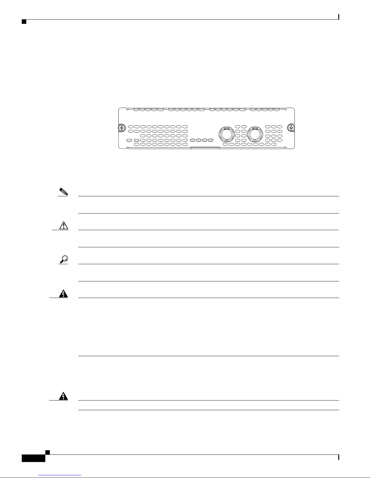
The Cisco SM-X-1T3/E3 is a single-port universal T3/E3 enhanced service module with integrated
CSU/DSU, clear channel, and subrate support. Channels on the service module can be configured as
either T3 or E3 using Cisco IOS software.
Figure 1 Cisco SM-X-1T3/E3 Enhanced Service Module Faceplate
Conventions
Note Means reader take note. Notes contain helpful suggestions or references to additional information and
material.
Caution This symbol means reader be careful. In this situation, you might do something that could result in
equipment damage or loss of data.
Tip Means the following information will help you solve a problem. The tips information might not be
troubleshooting or even an action, but could be useful information, similar to a Timesaver.
SM-X-1T3/E3
EN
AL
SEE MANUAL BEFORE INSTALLING NETWORK MODULE
RX
FERF/RAI
LP
CD
AIS
T3/E3
TX
300923
Warning
IMPORTANT SAFETY INSTRUCTIONS
This warning symbol means danger. You are in a situation that could cause bodily injury. Before you
work on any equipment, be aware of the hazards involved with electrical circuitry and be familiar
with standard practices for preventing accidents. Use the statement number provided at the end of
each warning statement to locate its translation in the translated safety warnings that accompanied
this device.
Statement 1071
SAVE THESE INSTRUCTIONS
Safety Warnings
Warning
Connecting Cisco T3 and E3 Service Modules to the Network
2
Read the installation instructions before connecting the system to the power source.
Statement 1004
OL-27149-01
Page 3

Connecting Cisco T3 and E3 Service Modules to the Network
Safety Warnings
Warning
Warning
Warning
Warning
Warning
Only trained and qualified personnel should be allowed to install, replace, or service this equipment.
Statement 1030
This equipment must be installed and maintained by service personnel as defined by AS/NZS 3260.
Incorrectly connecting this equipment to a general-purpose outlet could be hazardous. The
telecommunications lines must be disconnected 1) before unplugging the main power connector or 2)
while the housing is open, or both.
Statement 1043
Before working on a system that has an on/off switch, turn OFF the power and unplug the power cord.
Statement 1
This unit might have more than one power supply connection. All connections must be removed to
de-energize the unit.
Statement 1028
This equipment must be grounded. Never defeat the ground conductor or operate the equipment in the
absence of a suitably installed ground conductor. Contact the appropriate electrical inspection
authority or an electrician if you are uncertain that suitable grounding is available. Statement 1024
Warning
Warning
Warning
Warning
Warning
Hazardous network voltages are present in WAN ports regardless of whether power to the unit is OFF
or ON. To avoid electric shock, use caution when working near WAN ports. When detaching cables,
detach the end away from the unit first.
Statement 1026
Before opening the unit, disconnect the telephone-network cables to avoid contact with
telephone-network voltages.
Statement 1041
Before working on equipment that is connected to power lines, remove jewelry (including rings,
necklaces, and watches). Metal objects will heat up when connected to power and ground and can
cause serious burns or weld the metal object to the terminals.
Statement 43
Do not use this product near water; for example, near a bath tub, wash bowl, kitchen sink or laundry
tub, in a wet basement, or near a swimming pool.
Statement 1035
Never install telephone jacks in wet locations unless the jack is specifically designed for wet
locations.
Statement 1036
OL-27149-01
Connecting Cisco T3 and E3 Service Modules to the Network
3
Page 4
Connecting Cisco T3 and E3 Service Modules to the Network
Installing and Removing the Cisco SM-X-1T3/E3 on Second Generation Integrated Services Routers
Warning
Warning
Warning
Warning
Warning
Never touch uninsulated telephone wires or terminals unless the telephone line has been
disconnected at the network interface.
Avoid using a telephone (other than a cordless type) during an electrical storm. There may be a remote
risk of electric shock from lightning.
To report a gas leak, do not use a telephone in the vicinity of the leak.
There is the danger of explosion if the battery is replaced incorrectly. Replace the battery only with
the same or equivalent type recommended by the manufacturer. Dispose of used batteries according
to the manufacturer's instructions.
Blank faceplates and cover panels serve three important functions: they prevent exposure to
hazardous voltages and currents inside the chassis; they contain electromagnetic interference (EMI)
that might disrupt other equipment; and they direct the flow of cooling air through the chassis. Do not
operate the system unless all cards, faceplates, front covers, and rear covers are in place.
1029
Statement 1037
Statement 1038
Statement 1039
Statement 1015
Statement
Warning
Warning
No user-serviceable parts inside. Do not open.
For connections outside the building where the equipment is installed, the following ports must be
connected through an approved network termination unit with integral circuit protection.
Statement 1073
T3, E3 Statement 1044
Installing and Removing the Cisco SM-X-1T3/E3 on Second
Generation Integrated Services Routers
For information on installing Cisco SM-X-1T3/E3 Enhanced Service Modules on Second Generation
Integrated Services Routers (ISR G2), see Installing Cisco Network Modules and Service Modules in
Cisco Access Routers.
To operate the Cisco SM-X-1T3/E3 module on Cisco ISR G2 routers, use one of the following
Cisco IOS releases:
• 15.2(4)M4 or later
• 15.3(1)T2 or later
• 15.3(2)T1 later
Connecting Cisco T3 and E3 Service Modules to the Network
4
OL-27149-01
Page 5

Connecting Cisco T3 and E3 Service Modules to the Network
Installing and Removing the Cisco SM-X-1T3/E3 on Cisco 4451-X Integrated Services Routers
Installing and Removing the Cisco SM-X-1T3/E3 on Cisco 4451-X
Integrated Services Routers
This section describes the following tasks for the Cisco SM-X-1T3/E3 enhanced service module:
• Software Requirements for the Cisco SM-X-1T3/E3, page 5
• Removing the Cisco SM-X-1T3/E3 from a Cisco ISR 4451-X Router, page 6
• Installing the Cisco SM-X-1T3/E3 in a Cisco ISR 4451-X Router, page 6
• Verifying Cisco SM-X-1T3/E3 Installation in a Cisco ISR 4451-X Router, page 6
Caution Always wear an electrostatic discharge (ESD)-preventive wrist strap and ensure that it makes good
contact with your skin when you remove or install a service module (SM). Connect the equipment end
of the wrist strap to the metal part of the chassis.
Caution Handle service modules (SMs) by the edges only. SMs are ESD-sensitive components and can be
damaged by mishandling.
Software Requirements for the Cisco SM-X-1T3/E3
Cisco IOS XE Release 3.9.1 or later release is required to operate the Cisco SM-X-1T3/E3 enhanced
service module on Cisco ISR 4451-X routers.
To determine the version of Cisco IOS software that is running on your router, log in to the router and
enter the show version command:
Router> show version
Cisco IOS Software, IOS-XE Software (X86_64_LINUX_IOSD-UNIVERSALK9-M), Experimental
Version 15.3(20130513:160617)
[v153_2_s_xe39_throttle-BLD-BLD_V153_2_S_XE39_THROTTLE_LATEST_20130513_144824-ios 170]
Copyright (c) 1986-2013 by Cisco Systems, Inc.
Compiled Mon 13-May-13 14:05 by mcpre
IOS XE Version: BLD_V153_2_S
OL-27149-01
Connecting Cisco T3 and E3 Service Modules to the Network
5
Page 6

Connecting Cisco T3 and E3 Service Modules to the Network
Installing and Removing the Cisco SM-X-1T3/E3 on Cisco 4451-X Integrated Services Routers
Removing the Cisco SM-X-1T3/E3 from a Cisco ISR 4451-X Router
Use the following procedure to remove the Cisco SM-X-1T3/E3 from a Cisco ISR 4451-X Router:
Step 1 Read the “Safety Warnings” section on page -2 before you perform any module replacement.
Step 2 Locate the service module (SM) to be removed.
Step 3 Using a number 1 Phillips or flat-blade screwdriver, unscrew the captive mounting screws on the module
faceplate. See Figure 1.
Step 4 Pull the Cisco SM-X-1T3/E3 out of the chassis.
Step 5 Place the SM in an antistatic bag to protect it from electrostatic discharge (ESD) damage.
Installing the Cisco SM-X-1T3/E3 in a Cisco ISR 4451-X Router
Use the following procedure to install the Cisco SM-X-1T3/E3 on a Cisco ISR 4451-X Router:
Step 1 Read the “Safety Warnings” section on page -2 before you perform any module replacement.
Step 2 Remove the blank faceplates installed over the slot you intend to use.
Step 3 Push the Cisco SM-X-1T3/E3 into place until you feel the edge connector seat securely into the
connector on the router backplane. The module faceplate should contact the chassis rear panel.
Step 4 Using a number 1 Phillips or flat-blade screwdriver, tighten the captive mounting screws on the module
faceplate. See Figure 1.
Verifying Cisco SM-X-1T3/E3 Installation in a Cisco ISR 4451-X Router
Use the show diag command to verify that the Cisco SM-X-1T3/E3 has been installed correctly. In the
following example, one service module is recognized by the system.
router#show diag ?
all All related information
chassis Chassis related information
slot Slot location information for this command
subslot Subslot location information for this command
Router#show diag subslot 2/0 eeprom detail
Connecting Cisco T3 and E3 Service Modules to the Network
6
OL-27149-01
Page 7

Connecting Cisco T3 and E3 Service Modules to the Network
SPA EEPROM data for subslot 2/0:
EEPROM version : 4
Compatible Type : 0xFF
Controller Type : 1909
Hardware Revision : 1.0
PCB Part Number : 73-14154-02
Top Assy. Part Number : 800-36532-01
Board Revision : 06
Deviation Number : 123598
Fab Version : 02
PCB Serial Number : FOC15495HU1
Asset ID : REV 2F
Product Identifier (PID) : SM-X-1T3/E3
Version Identifier (VID) : V01
CLEI Code : TBD
Base MAC Address : C4 0A CB 56 00 99
MAC Address block size : 3
Manufacturing Test Data : 00 00 00 00 00 00 00 00
Environment Monitor Data : 40 0B E3 43 00 0A
Platform features : 02 01 01 0A 00 00 00 00
01 01 00
Connecting Cisco SM-X-1T3/E3 Service Modules to the Network
Connecting Cisco SM-X-1T3/E3 Service Modules to the Network
To connect a Cisco SM-X-1T3/E3 enhanced service module to the network, use a 75-ohm 728-A coaxial
cable to connect the BNC connector on the service module to a networking device (see Figure 2).
Warning
Warning
Warning
Warning
Warning
Only trained and qualified personnel should be allowed to install, replace, or service this equipment.
Statement 1030
No user-serviceable parts inside. Do not open.
Statement 1073
Ultimate disposal of this product should be handled according to all national laws and regulations.
Statement 1040
Read the installation instructions before connecting the system to the power source.
Installation of the equipment must comply with local and national electrical codes.
Statement 1004
Statement 1074
Warning
This equipment must be grounded. Never defeat the ground conductor or operate the equipment in the
absence of a suitably installed ground conductor. Contact the appropriate electrical inspection
authority or an electrician if you are uncertain that suitable grounding is available.
OL-27149-01
Statement 1024
Connecting Cisco T3 and E3 Service Modules to the Network
7
Page 8

Connecting Cisco SM-X-1T3/E3 Service Modules to the Network
Connecting Cisco T3 and E3 Service Modules to the Network
Warning
Blank faceplates and cover panels serve three important functions: they prevent exposure to
hazardous voltages and currents inside the chassis; they contain electromagnetic interference (EMI)
that might disrupt other equipment; and they direct the flow of cooling air through the chassis. Do not
operate the system unless all cards, faceplates, front covers, and rear covers are in place.
Statement
1029
Warning
For connections outside the building where the equipment is installed, the following ports must be
connected through an approved network termination unit with integral circuit protection. T3/E3
Statement 1044
Warning
To comply with the Telcordia GR-1089 NEBS standard for electromagnetic compatibility and safety,
connect the SM-X-1T3/E3 interface ports only to intra-building or unexposed wiring or cable. The
intrabuilding cable must be shielded and the shield must be grounded at both ends. The intra-building
port(s) of the equipment or subassembly must not be metallically connected to interfaces that connect
to the OSP or its wiring. These interfaces are designed for use as intra-building interfaces only (Type
2 or Type 4 ports as described in GR-1089-CORE) and require isolation from the exposed OSP cabling.
The addition of Primary Protectors is not sufficient protection in order to connect these interfaces
metallically to OSP wiring.
Caution To minimize transient surges, the internal wiring should not be routed in the same conduit with power
Statement 7003
lines or external telephone lines.
Connecting Cisco T3 and E3 Service Modules to the Network
8
OL-27149-01
Page 9

Connecting Cisco T3 and E3 Service Modules to the Network
SEE MANUAL BEFORE INSTALLING NETWORK MODULE
SM-X-1T3/E3
LP
AIS
EN
CD
RX
TX
FERF/RAI
T3/E3
AL
300924
SUPERVISOR2
WS-X6K-SUP2-2GE
STATUS
SYSTEM
CONSOLE
PWR MGMT
RESET
CONSOLE
CONSOLE
PORT
MODE
PCMCIA
EJECT
PORT 1
PORT 2
Switch Load
100%
1%
LINK
LINK
OSM-4OC12 POS-SI
4 PORT OC-12 POS SM IR
STATUS
1
1
2
2
3
3
4
4
RESET
LINK
LINK
LINK
LINK
CARRIER
ALARM
CARRIER
ALARM
CARRIER
ALARM
CARRIER
ALARM
ACTIVE
TX
RX
TX
PORT 1
RX
ACTIVE
TX
RX
TX
PORT 2
RX
ACTIVE
TX
RX
TX
PORT 3
RX
ACTIVE
TX
RX
TX
PORT4
RX
OSM-4OC12 POS-SI
4 PORT OC-12 POS SM IR
STATUS
1
1
2
2
3
3
4
4
RESET
LINK
LINK
LINK
LINK
CARRIER
ALARM
CARRIER
ALARM
CARRIER
ALARM
CARRIER
ALARM
ACTIVE
TX
RX
TX
PORT 1
RX
ACTIVE
TX
RX
TX
PORT 2
RX
ACTIVE
TX
RX
TX
PORT 3
RX
ACTIVE
TX
RX
TX
PORT4
RX
TX
RX
RX
TX
300925
SEE MANUAL BEFORE INSTALLING NETWORK MODULE
SM-X-1T3/E3
LP
AIS
EN
CD
RX
TX
FERF/RAI
T3/E3
AL
CD
LED
LP
LED
FERF/RAI
LED
AIS
LED
AL
LED
EN
LED
Figure 2 Connecting a T3/E3 Service Module to a Networking Device
Cisco SM-X-1T3/E3 Service Module LEDs
Tip When connecting the Cisco SM-X-1T3/E3 service module to a port adapter used in another router series,
verify that you are connecting the TX port on the service module with the RX port on the port adapter,
and the TX port on the port adapter to the RX port on the service module.
Cisco SM-X-1T3/E3 Service Module LEDs
The Cisco SM-X-1T3/E3 enhanced service module includes several indicator LEDs. Figure 3 and
Table 1 describe the LEDs on the T3/E3 enhanced service module.
Figure 3 Cisco SM-X-1T3/E3 LEDs
OL-27149-01
Connecting Cisco T3 and E3 Service Modules to the Network
9
Page 10

Cisco SM-X-1T3/E3 Service Module LEDs
Table 1 Cisco SM-X-1T3/E3Service Module LEDs
LED Meaning
EN Green indicates that the service module has passed its self-test and is
AL Yellow indicates that the port is out of frame.
CD Green indicates that the signal is present on the port.
LP Yellow indicates that a loopback condition is present on the port.
AIS Yellow indicates an alarm on the DS3 transmission.
FERF/RAI Yellow indicates a remote failure at the far end of the connection.
Connecting Cisco T3 and E3 Service Modules to the Network
available to the router.
Connecting Cisco T3 and E3 Service Modules to the Network
10
OL-27149-01
Page 11

Connecting Cisco T3 and E3 Service Modules to the Network
Additional References
Additional References
• Related Documents, page 11
• Technical Assistance, page 11
Related Documents
Related Topic Document Title
Configuring Cisco SM-X-1T3/E3 software Cisco SM-X-1T3/E3 Enhanced Service Module Configuration Guide
Regulatory compliance and safety information Cisco Service Module Regulatory Compliance and Safety
Information
Technical Assistance
Description Link
The Cisco Support and Documentation website
provides online resources to download documentation,
software, and tools. Use these resources to install and
configure the software and to troubleshoot and resolve
technical issues with Cisco products and technologies.
Access to most tools on the Cisco Support and
Documentation website requires a Cisco.com user ID
and password.
http://www.cisco.com/cisco/web/support/index.html
Cisco and the Cisco Logo are trademarks of Cisco Systems, Inc. and/or its affiliates in the U.S. and other countries. A listing of Cisco's trademarks
can be found at www.cisco.com/go/trademarks. Third party trademarks mentioned are the property of their respective owners. The use of the word
partner does not imply a partnership relationship between Cisco and any other company. (1005R)
Any Internet Protocol (IP) addresses and phone numbers used in this document are not intended to be actual addresses and phone numbers. Any
examples, command display output, network topology diagrams, and other figures included in the document are shown for illustrative purposes only.
Any use of actual IP addresses or phone numbers in illustrative content is unintentional and coincidental.
© 2013 Cisco Systems, Inc. All rights reserved.
OL-27149-01
Connecting Cisco T3 and E3 Service Modules to the Network
11
Page 12

Additional References
Connecting Cisco T3 and E3 Service Modules to the Network
Connecting Cisco T3 and E3 Service Modules to the Network
12
OL-27149-01
 Loading...