

Page 1
Cisco Small Business
WRP400 Wireless-G Broadband Router with 2 Phone
Ports
USER GUIDE
Page 2

6bZg^XVh=ZVYfjVgiZgh
8^hXdHnhiZbh!>cX#
HVc?dhZ!86
6h^VEVX^[^X=ZVYfjVgiZgh
8^hXdHnhiZbhJH6EiZ#AiY#
H^c\VedgZ
:jgdeZ=ZVYfjVgiZgh
8^hXdHnhiZbh>ciZgcVi^dcVa7K
6bhiZgYVb!I]ZCZi]ZgaVcYh
8^hXd]VhbdgZi]Vc '%%d[[^XZhldgaYl^YZ#6YYgZhhZh!e]dcZcjbWZgh!VcY [VmcjbWZghVgZa^hiZYdci]Z8^hXdLZWh^iZVilll#X^hXd#Xdb$\d$d[[^XZh#
889:!88:CI!8^hXd:dh!8^hXdAjb^c!8^hXdCZmjh!8^hXdHiVY^jbK^h^dc!8^hXdIZaZEgZhZcXZ!8^hXdLZW:m!i]Z8^hXdad\d!98:!VcYLZaXdbZidi]Z=jbVcCZildg`VgZigVYZbVg`h08]Vc\^c\i]ZLVnLZLdg`!
A^kZ!EaVn!VcYAZVgcVcY8^hXdHidgZVgZhZgk^XZbVg`h0VcY6X XZhhGZ\^higVg!6^gdcZi!6hncXDH!7g^c\^c\i]ZBZZi^c\IdNdj!8ViVanhi!8896!889E!88>:!88>E!88C6!88CE!88HE!88KE!8^hXd!i]Z8^hXd8Zgi^[^ZY
>ciZgcZildg`:meZgiad\d!8^hXd>DH!8^hXdEgZhh!8^hXdHnhiZbh!8^hXdHnhiZbh8Ve^iVa!i]Z8^hXdHnhiZbhad\d!8^hX dJc^in!8daaVWdgVi^dcL^i]djiA^b^iVi^dc!:i]Zg;Vhi!:i]ZgHl^iX]!:kZci8ZciZg!;VhiHiZe!;daadlBZ
7gdlh^c\!;dgbH]VgZ!<^\V9g^kZ!=dbZA^c`!>ciZgcZiFjdi^Zci!>DH!^E]dcZ!^Fj^X`HijYn!>gdcEdgi!i]Z>gdcEdgiad \d!A^\]iHigZVb!A^c`hnh!BZY^VIdcZ!BZZi^c\EaVXZ!BZ Zi^c\EaVXZ8]^bZHdjcY!B<M!CZildg`Zgh!CZildg`^c\
6XVYZbn!CZildg`GZ\^higVg!E8Cdl!E>M!EdlZgEVcZah!Egd8dccZXi!HXg^eiH]VgZ!HZcYZg7VhZ!HB6GIcZi!HeZXigjb:meZgi!HiVX`L^hZ!I]Z;VhiZhiLVnid>cXgZVhZNdjg>ciZgcZiFjdi^Zci!IgVchEVi]!LZW:m!VcYi]ZLZW:m
ad\dVgZgZ\^hiZgZYigVYZbVg`hd[8^hXdHnhiZbh!>cX#VcY$dg^ihV[[^a^ViZh^ci]ZJc^iZYHiViZhVcYXZgiV^cdi]ZgXdjcig^Zh#
6aadi]ZgigVYZbVg`hbZci^dcZY^ci]^hYdXjbZcidglZWh^iZVgZi]ZegdeZgind[i]Z^ggZheZ Xi^kZdlcZgh#I]ZjhZd[i]ZldgYeVgicZgYdZhcdi^beanVeVg icZgh]^egZaVi^dch]^eWZilZZc8^hXdVcYVcndi]ZgXdbeVcn#%-%.G
6bZg^XVh=ZVYfjVgiZgh
8^hXdHnhiZbh!>cX#
HVc?dhZ!86
6h^VEVX^[^X=ZVYfjVgiZgh
8^hXdHnhiZbhJH6EiZ#AiY#
H^c\VedgZ
:jgdeZ=ZVYfjVgiZgh
8^hXdHnhiZbh>ciZgcVi^dcVa7K
6bhiZgYVb!I]ZCZi]ZgaVcYh
© 2009 Cisco Systems, Inc. All rights reserved. OL-18475-01
Page 3

Contents
Chapter 1: Getting to Know the WRP400 9
Front Panel 9
Back Panel 12
Side Panel 13
Placement Positions 13
Chapter 2: Before You Begin: Understanding Wireless Security 16
Change the Default Wireless Network Name or SSID 16
Change the Default Router Password 17
Enable MAC Address Filtering for Wireless Access 17
Enable Encryption 17
General Network Security Guidelines 18
Additional Security Tips 18
Chapter 3: Using the Web-Based Utility for Advanced Configuration 19
How to Access the Web-Based Utility 20
Chapter 4: Basic Settings 22
Setup > Basic Setup 23
Internet Setup 23
Network Setup 30
Time Setting 33
Setup > DDNS 34
DynDNS.org 34
TZO.com 36
Setup > MAC Address Clone 37
Setup > Advanced Routing 38
Advanced Settings: PPPoE Relay 39
Advanced Routing 39
Cisco WRP400 User Guide i
Page 4

Contents
Chapter 5: Installing and Configuring Your Mobile Network 41
Installing Your USB Modem 42
Setup > Mobile Network 43
Setup > Connection Recovery 46
Recovery & Failover 47
WAN Interfaces 48
Understanding the LED Behavior for Mobile Network 49
LED Behavior During USB Modem Installation 49
LED Behavior During Mobile Network Connectivity 49
Chapter 6: Configuring Your Wireless Network 51
Wireless > Basic Wireless Settings 51
Manual Configuration of the Network 52
Wi-Fi Protected Setup 54
Wireless > Wireless Security 56
WEP 57
WPA Personal 58
WPA2 Personal 59
WPA Enterprise 60
WPA2 Enterprise 61
Wireless > Wireless MAC Filter 62
Wireless > Advanced Wireless Settings 64
Chapter 7: Configuring Network Security and Controlling Internet Access 66
Security > Firewall 66
Firewall 67
Internet Filter 67
Web Filter 68
Security > VPN Passthrough 68
Access Restrictions > Internet Access 69
Creating or Modifying an Internet Access Policy 73
Cisco WRP400 User Guide ii
Page 5

Contents
Chapter 8: Configuring Applications and Gaming 75
Applications and Gaming > Single Port Forwarding 76
Applications and Gaming > Port Range Forward 77
Applications & Gaming > Port Range Triggering 79
Applications and Gaming > DMZ 80
Applications and Gaming > QoS 81
Chapter 9: Administration 87
Administration > Management 88
Management 89
IGMP 91
Administration > Log 91
Administration > Diagnostics 93
Ping Test 93
Traceroute Test 94
Administration > Factory Defaults 96
Administration > Firmware Upgrade 97
Username & Password 97
Firmware Upgrade 98
Administration > Config Management 99
Backup Configuration 100
Restore Configuration 100
Administration > Reboot 100
Chapter 10: Using the Status Screens 101
Status > Router 102
Router Information 102
Internet Connection 103
Status > Mobile Network 104
Mobile Network Status 104
Data Card Status 105
Cisco WRP400 User Guide iii
Page 6

Contents
Status > Local Network 106
Local Network 106
DHCP Server 106
Status > Wireless Network 108
Chapter 11: Configuring Voice Services 109
Access to the Voice Screens 109
Voice > Info 110
Product Information 111
System Status 111
Line 1/2 Status 112
Voice > System 113
System Configuration 114
Miscellaneous Settings 114
Voice > User 1/2 114
Call Forward Settings 116
Selective Call Forward Settings 116
Speed Dial Settings 116
Supplementary Service Settings 117
Distinctive Ring Settings 117
Ring Settings 117
Voice > Admin Login 118
Chapter 12: Interactive Voice Response Menu 119
Overview 119
Menu Commands 119
Appendix A:Troubleshooting 121
General Troubleshooting 121
Mobile Network Troubleshooting 125
Cisco WRP400 User Guide iv
Page 7

Contents
Appendix B:Specifications 128
Appendix C:Regulatory Information 134
Appendix D:Where to Go From Here 153
Cisco WRP400 User Guide v
Page 8
Finding Information in PDF Files
The WRP400 documents are published as PDF files. The PDF Find/Search tool
within Adobe® Reader® lets you find information quickly and easily online. You
can perform the following tasks:
• Search an individual PDF file.
• Search multiple PDF files at once (for example, all PDFs in a specific folder
or disk drive).
• Perform advanced searches.
Finding Text in a PDF
Follow this procedure to find text in a PDF file.
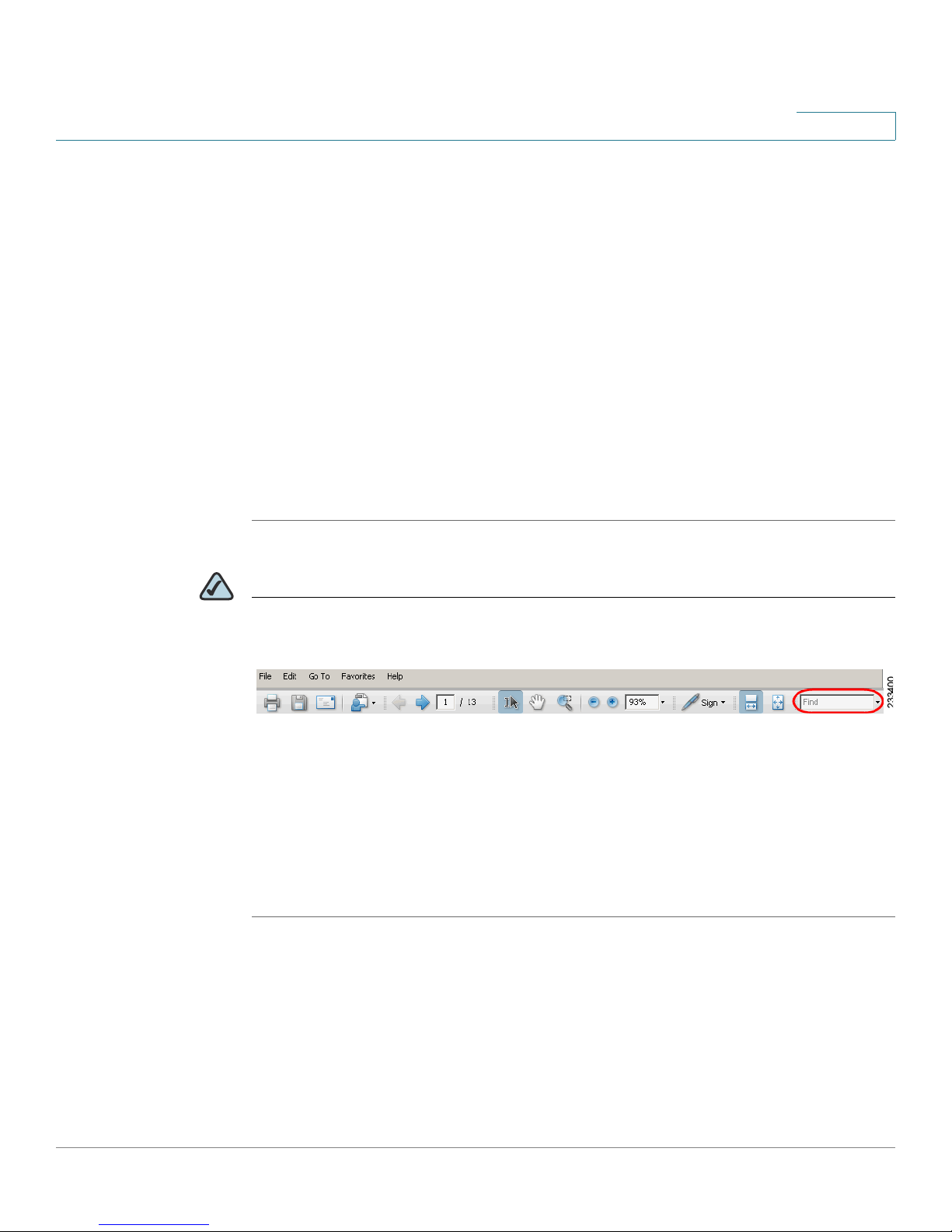
STEP 1 Enter your search terms in the Find text box on the toolbar.
Preface
NOTE By default, the Find tool is available at the right end of the Acrobat toolbar. If the
Find tool does not appear, choose Edit > Find.
STEP 2 Optionally, click the arrow next to the Find text box to refine your search by
choosing special options such as Whole Words Only.
STEP 3 Press Enter.
STEP 4 Acrobat displays the first instance of the search term.
STEP 5 Press Enter again to continue to more instances of the term.
Cisco WRP400 User Guide 6
Page 9
Finding Text in Multiple PDF Files
The
Search
on your PC or local network. The PDF files do not need to be open.
STEP 1 Start Acrobat Professional or Adobe Reader.
window lets you search for terms in multiple PDF files that are stored
Preface
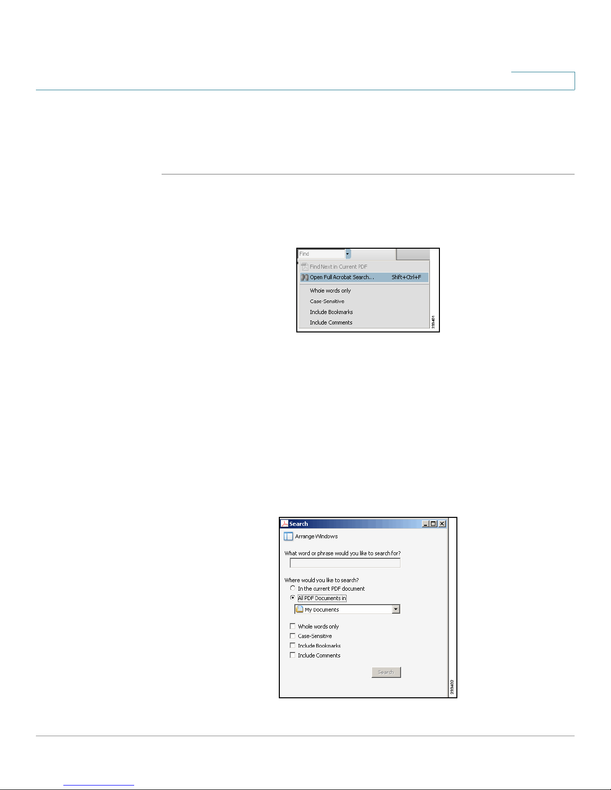
STEP 2 Choose Edit > Search, or click the arrow next to the
Open Full Acrobat Search.
STEP 3 In the
a. Enter the text that you want to find.
b. Choose All PDF Documents in.
c. If you want to specify additional search criteria, click Use Advanced Search
d. Click Search.
Search
From the drop-down box, choose Browse for Location. Then choose the
location on your computer or local network, and click OK.
Options, and choose the options you want.
window, complete the following steps:
Find
box and then choose
Cisco WRP400 User Guide 7
Page 10
Preface
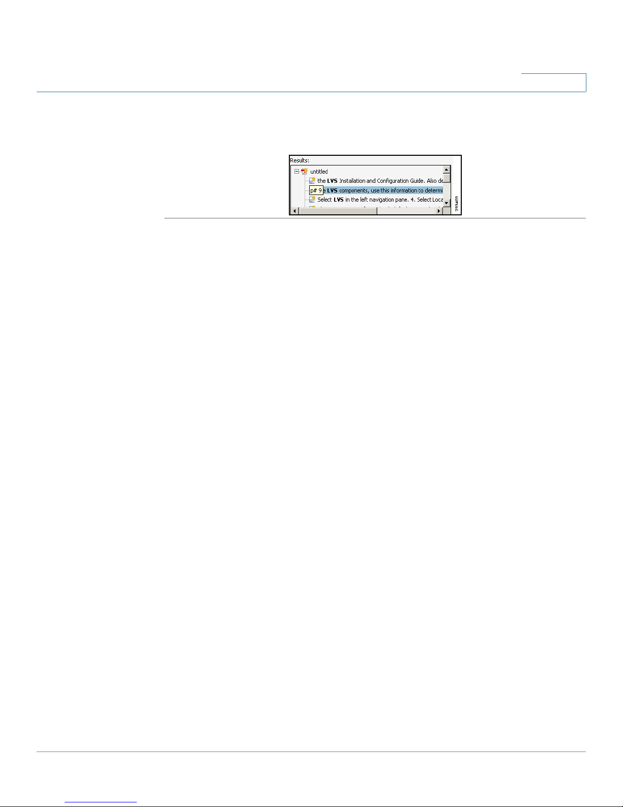
STEP 4 When the Results appear, click + to open a folder, and then click any link to open
the file where the search terms appear.
For more information about the Find and Search functions, see the Adobe Acrobat
online help.
Cisco WRP400 User Guide 8
Page 11
Getting to Know the WRP400
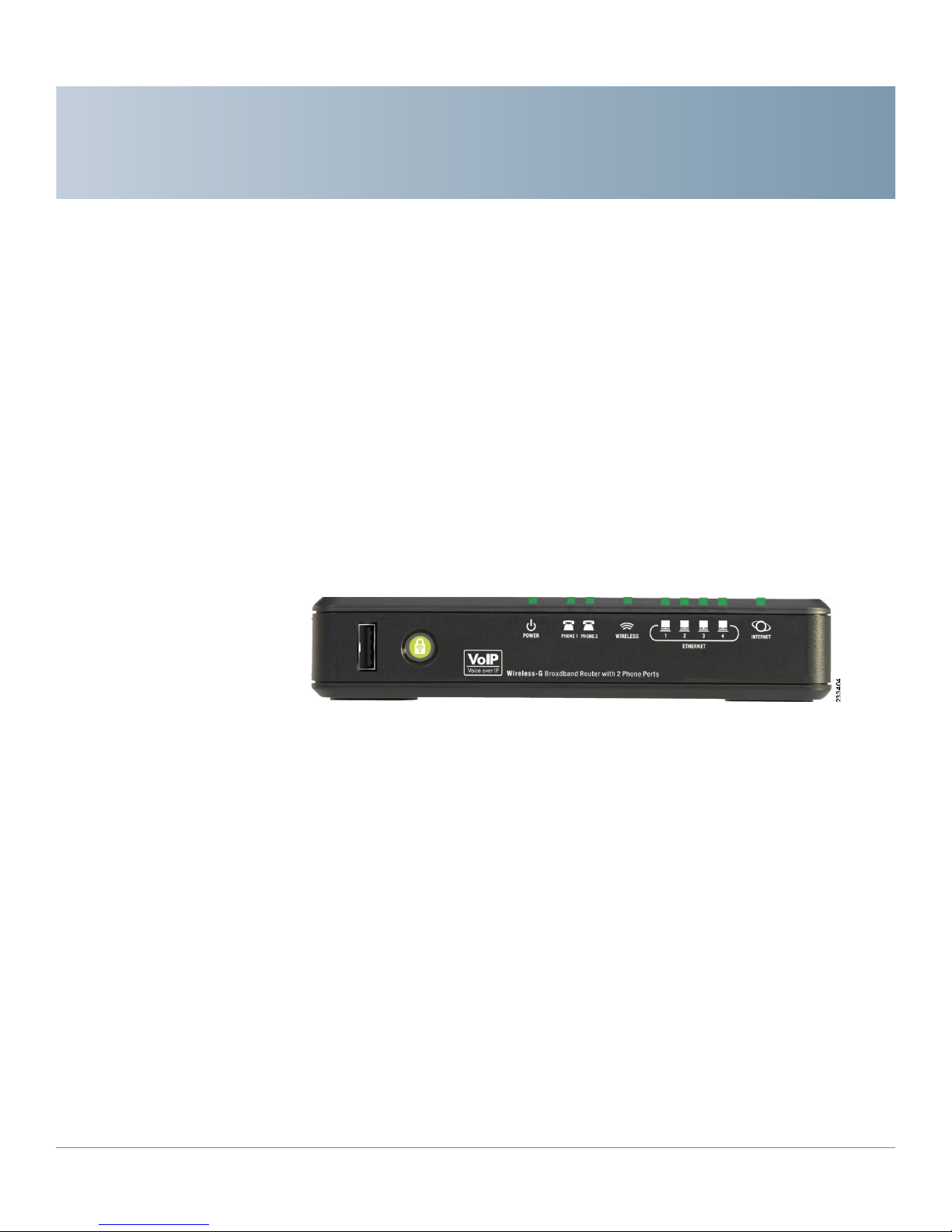
Thank you for choosing the Cisco WRP400 Wireless-G Broadband Router with 2
Phone Ports. The WRP400 lets you access the Internet via a wireless connection
or through one of its four switched ports. You can also use the WRP400 to share
resources such as computers, printers and files. The built-in phone adapter
enables Voice-over-IP (VoIP) calls even while you are using the Internet.
1
Front Panel
Cisco WRP400 User Guide 9
Page 12
Getting to Know the WRP400
Front Panel
LED Description
1
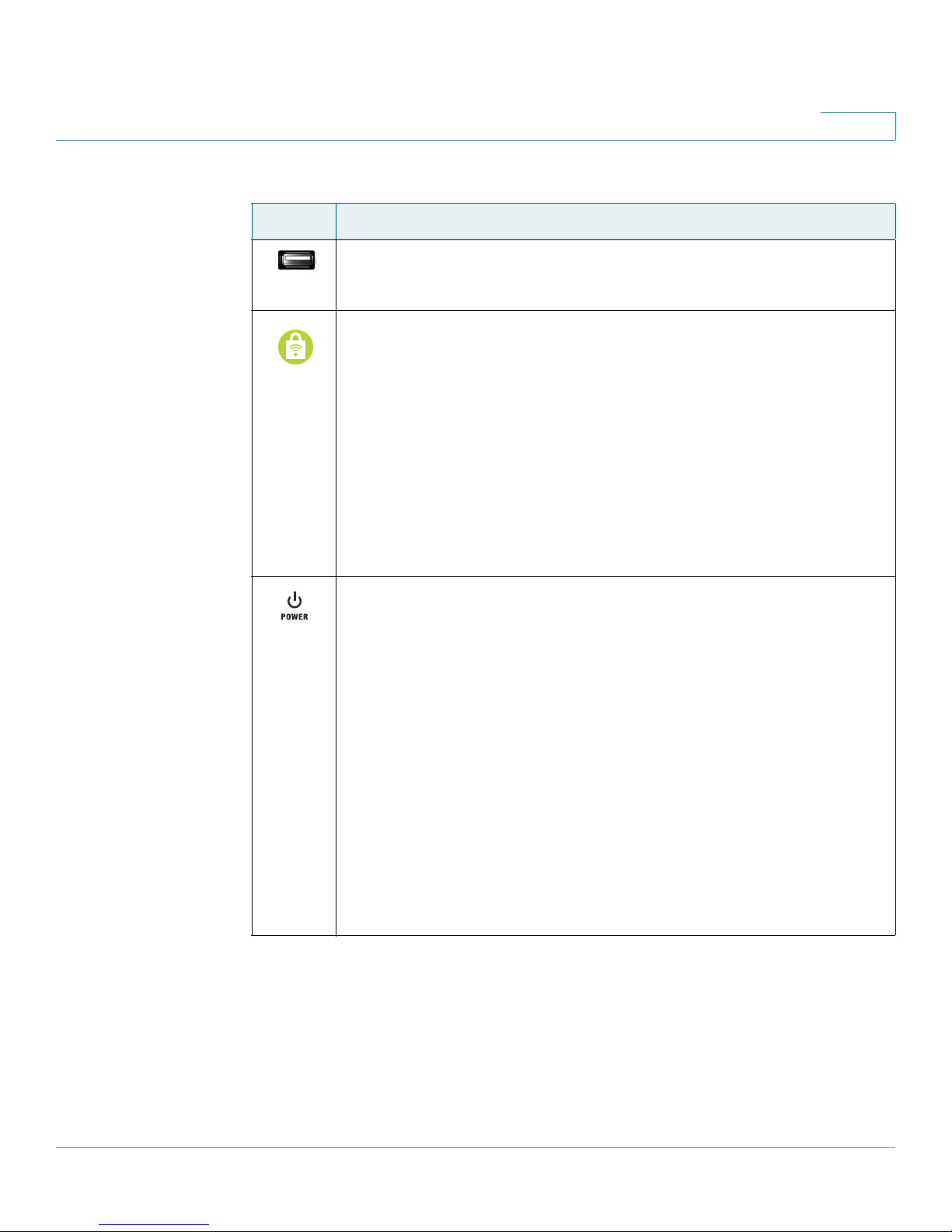
For information about supported USB devices, visit the WRP400
USB:
product page on Cisco.com: http://www.cisco.com/en/US/products/
ps10028/index.html
Wi-Fi Protected Setup (White/Orange): If you have client devices,
such as wireless adapters, that support Wi-Fi Protected Setup, then
you can use Wi-Fi Protected Setup to automatically configure
wireless security for your wireless network(s).
To use Wi-Fi Protected Setup, run the Setup Wizard, or refer to
“Wireless > Basic Wireless Settings,” on page 39.
The Wi-Fi Protected Setup button lights up white and stays on while
wireless security is enabled on your wireless network(s). The LED
lights up orange if there is an error during the Wi-Fi Protected Setup
process. Make sure the client device supports Wi-Fi Protected
Setup. Wait until the LED is off, and then try again.
Power (Green/Red/Orange): This LED indicates the status of power
and the progress of the self-diagnostic test upon bootup. If a USB
modem is connected to the USB port, this LED indicates the progress
of initialization and the status of the mobile network connection.
•
Power: The Power LED shines green and stays on while the WRP400 is
powered on. If the LED shines red, verify that the correct power adapter
is used. If the LED remains red, contact your service provider for
support.
• Self-diagnostic test: During boot-up, the LED flashes green to indicate
that the self-diagnostic test is in progress. When the test is complete,
the LED shines steady green.
• Initialization of a USB modem: When you connect a device to the USB
port, the Power LED flashes green and orange, indicating that
initialization is in progress. After the device initializes, the Power LED
shines steady green. If the device fails to initialize, the LED continues to
flash green and orange.
Cisco WRP400 User Guide 10
Page 13
Getting to Know the WRP400
Front Panel
LED Description
1
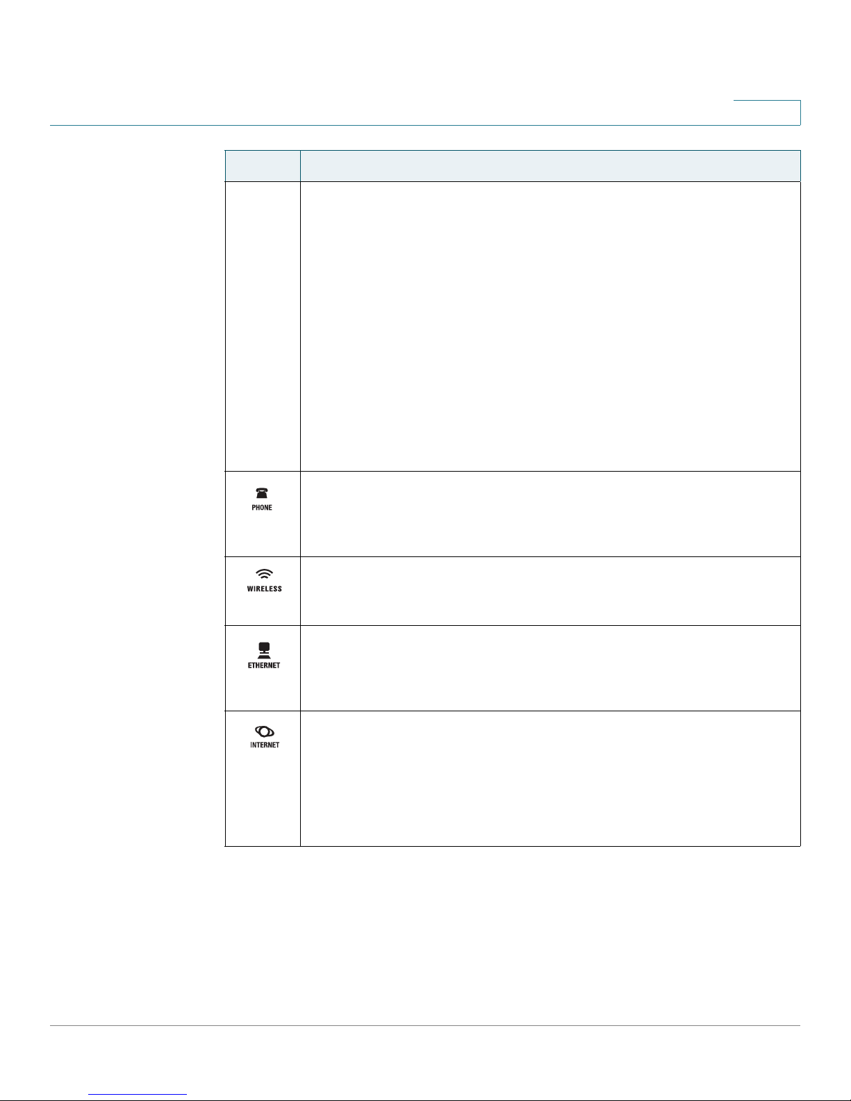
• Mobile network connection: If a USB modem is installed, the mobile
network connection is used as a failover when an Ethernet connection is
unavailable. The Power LED shows the status of the mobile network:
• Flashing Orange: The WRP400 is attempting to connect to the
Internet through the mobile network connection.
• Steady Orange: The WRP400 is connected to the Internet through
the mobile network connection.
• Continuous Flashing Orange: The WRP400 failed to connect to the
Internet through the mobile network connection and is trying again.
• Steady Green: If a USB device is connected, this LED behavior
indicates that the device was successfully initialized and that the
WRP400 is not using the mobile network connection. If the USB
device is removed, this LED behavior indicates that theWRP400 has
power.
Phone 1-2 (Green): The Phone 1 or 2 LED lights up and stays on
when an active line is registered to the corresponding port on the
back panel. The LED slowly flashes when voicemail messages are
waiting.
Wireless (Green): The Wireless LED lights up when the wireless
feature is enabled. It flashes when the WRP400 is actively sending or
receiving data over the network.
Ethernet 1-4 (Green): These numbered LEDs, corresponding with
the numbered ports on the back panel, serve two purposes. If the
LED is solidly lit, the WRP400 is connected to a device through that
port. It flashes to indicate network activity over that port.
Internet (Green): The Internet LED lights up and stays on when an
Internet connection is made through the Internet port. It flashes to
indicate network activity over the Internet port.
NOTE: The Power LED indicates Internet connectivity through the
mobile network connection. See the information for the Power LED in
this table.
Cisco WRP400 User Guide 11
Page 14
Getting to Know the WRP400
Back Panel
Back Panel
Port Description
1
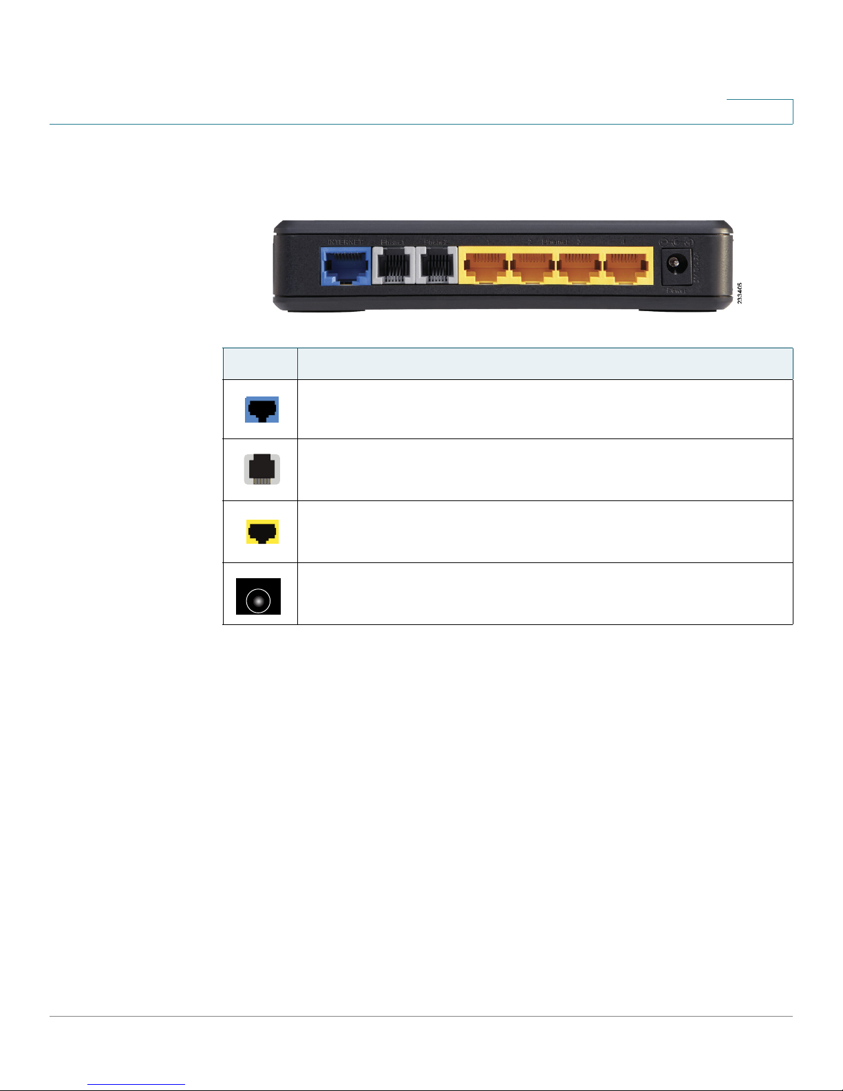
Internet: Use this port to connect the WRP400 to a cable or DSL
Internet connection.
Phone 1-2: Use these ports to connect standard analog telephones
to the WRP400.
Ethernet 1, 2, 3, 4: Use these Ethernet ports to connect the WRP400
to wired computers and other Ethernet network devices.
Power: Use the power port to connect the power adapter.
Cisco WRP400 User Guide 12
Page 15
Getting to Know the WRP400
Side Panel
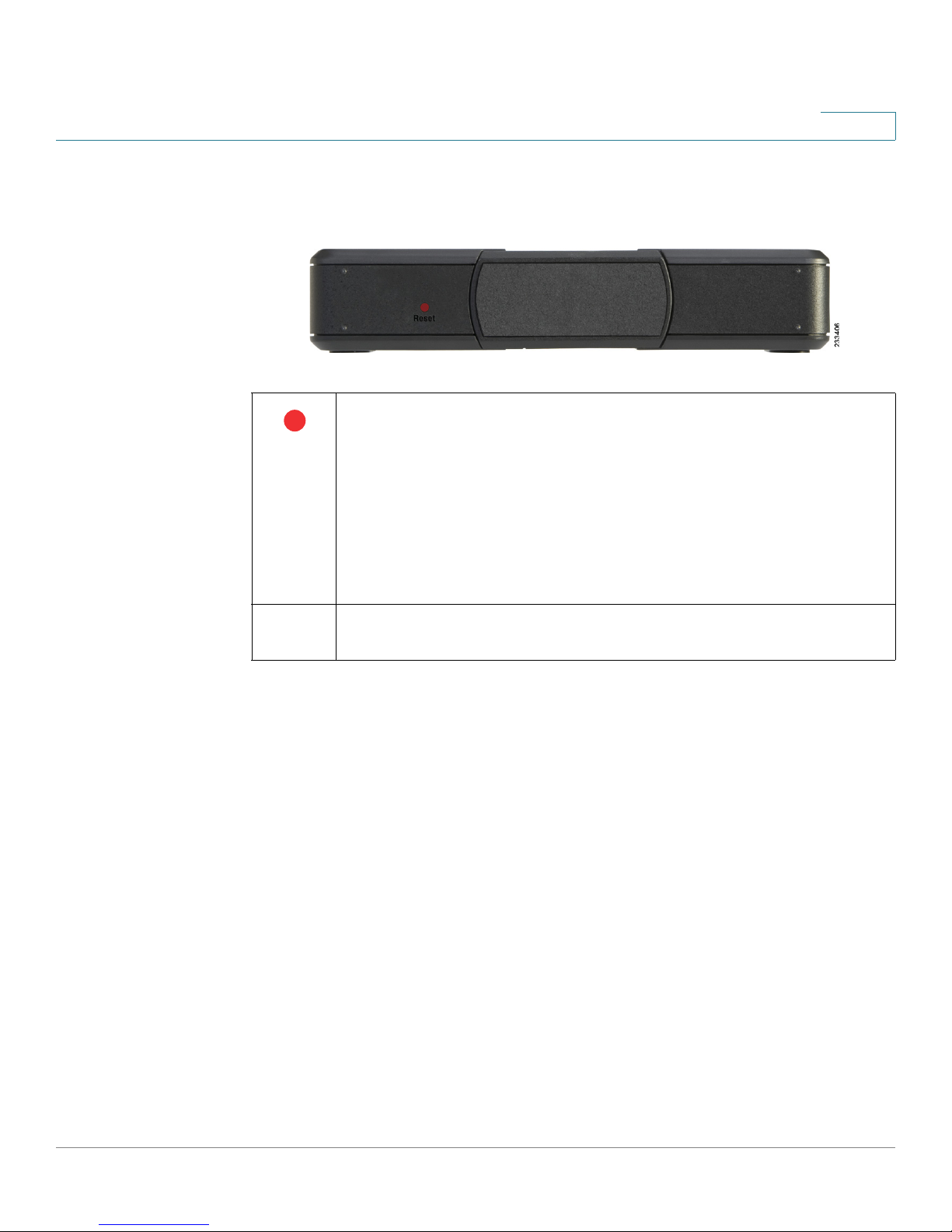
Side Panel
1
Reset: There are two ways to reset the WRP400 to the factory
default settings. Either press and hold the Reset button for
approximately ten seconds, or restore the defaults from the
Administration >Factory Defaults screen of the administration web
server. (The Factory Defaults screen allows you to restore the router
and voice defaults separately.)
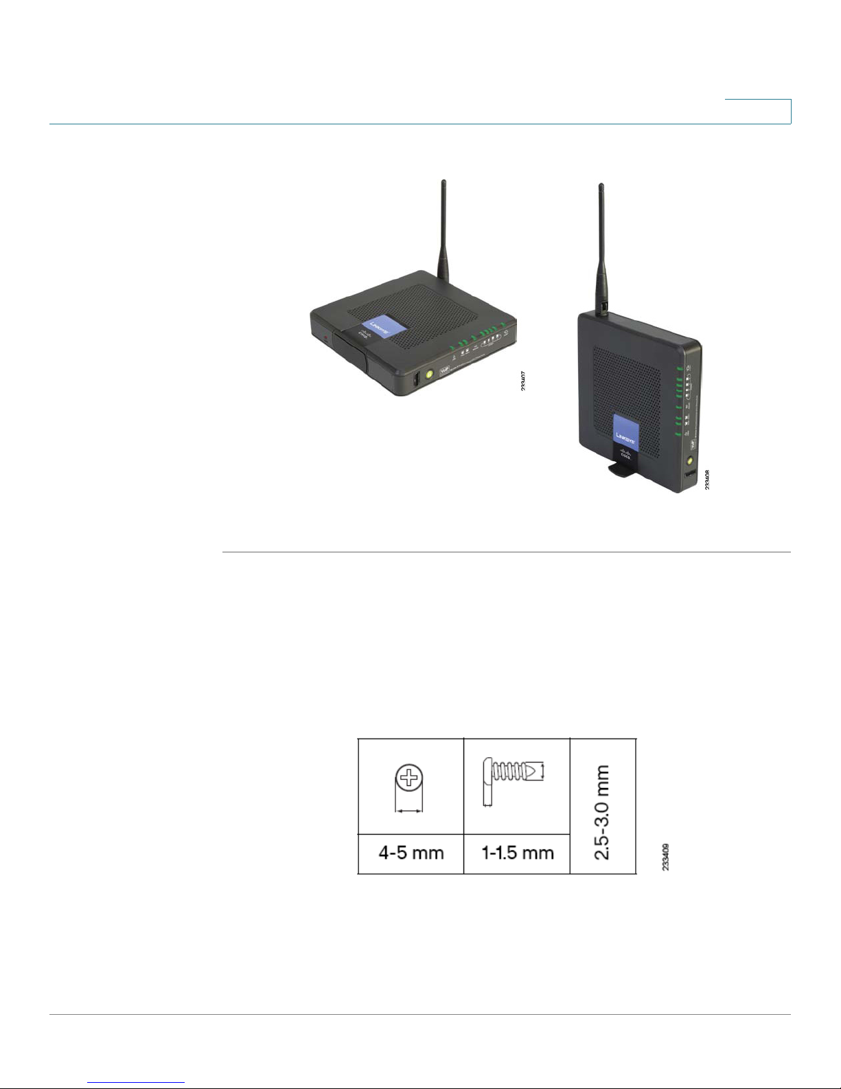
Placement Positions
There are three ways to physically install the WRP400:
• Horizontal Placement: The WRP400 has four rubber feet on the bottom
panel. Place the WRP400 on a level surface near an electrical outlet.
• Vertical Placement: The WRP400 has a stand on the side panel opposite to
the antenna. Rotate the stand 90 degrees, and place the WRP400 on a level
surface near an electrical outlet.
• Wall-Mounting Placement: The WRP400 has four wall-mount slots on its
back panel.
NOTE: Restoring the voice defaults may require your login (the
default user name and password are admin). If the defaults do not
work, contact your service provider for more information.
Stand: To place the WRP400 in a vertical position, rotate the stand 90
degrees.
Cisco WRP400 User Guide 13
Page 16
Getting to Know the WRP400
Placement Positions
Figure 1 Horizontal and Vertical Placement Options
1
To mount the WRP400 on a wall, follow these instructions:
STEP 1 Choose a wall that is smooth, flat, dry, and sturdy. Make sure that an electrical
outlet is nearby.
STEP 2 Obtain mounting hardware. Suggested hardware is illustrated below (not true to
scale).
Figure 2 Mounting Hardware
Cisco WRP400 User Guide 14
Page 17

Getting to Know the WRP400
Placement Positions
STEP 3 Drill two holes, 60 mm (2.36 inches) apart. Insert a screw into each hole and leave
3 mm (0.12 inches) of the head exposed.
To create a template to position the screws, you can print this page at 100 percent.
Then cut along the dotted line. Affix this template to the wall where you want to
drill the holes.
Figure 3 Wall Mount Template
1
NOTE Cisco is not responsible for damages incurred by insecure wall-mounting
hardware.
STEP 4 Position the WRP400 so that two of the wall-mount slots are over the two screws.
Slide the WRP400 down until the screws fit snugly into the wall-mount slots.
Cisco WRP400 User Guide 15
Page 18

2
Before You Begin: Understanding Wireless
Security
Wireless networks are convenient and easy to install, so homes with high-speed
Internet access are adopting them at a rapid pace. Because wireless networking
operates by sending information over radio waves, it can be more vulnerable to
intruders than a traditional wired network. Like signals from your cellular or
cordless phones, signals from your wireless network can also be intercepted.
Because you cannot physically prevent someone from connecting to your
wireless network, you need to take some additional steps to keep your network
secure.
NOTE The Setup Wizard guides you through the process of completing the tasks that are
described below. You are strongly encouraged to use the Setup Wizard for initial
configuration of the WRP400.
Change the Default Wireless Network Name or SSID
Wireless devices have a default wireless network name or Service Set Identifier
(SSID) set by the factory. This is the name of your wireless network, and can be up
to 32 characters in length. To distinguish your wireless network from other
wireless networks that may exist around you, you should change the default
wireless network name to something easily recognizable, but do not use personal
information (such as your Social Security number) because this information may
be available for anyone to see when browsing for wireless networks. For more
information, see “Wireless > Basic Wireless Settings,” on page 51.
Cisco WRP400 User Guide 16
Page 19

Before You Begin: Understanding Wireless Security
Change the Default Router Password
Change the Default Router Password
When you connect to the administration web server, you will be asked for a
password. The WRP400 has a default password set by the factory. The default
password is admin. Hackers know the defaults and may try to use them to access
your wireless device and change your network settings. To prevent unauthorized
access, change the password to one that is hard to guess. For more information,
see “Administration > Management,” on page 88.
Enable MAC Address Filtering for Wireless Access
The Cisco WRP400 gives you the ability to enable Media Access Control (MAC)
address filtering. The MAC address is a unique series of numbers and letters
assigned to every networking device. With MAC address filtering enabled,
wireless network access is provided solely for wireless devices with specific
MAC addresses. For example, you can specify the MAC address of each
computer in your home so that only those computers can access your wireless
network. For more information, see “Wireless > Wireless MAC Filter,” on
page 62.
2
Enable Encryption
Encryption protects data transmitted over a wireless network. Wi-Fi Protected
Access (WPA/WPA2) and Wired Equivalency Privacy (WEP) offer different levels
of security for wireless communication.
A network encrypted with WPA/WPA2 is more secure than a network encrypted
with WEP, because WPA/WPA2 uses dynamic key encryption. To protect the
information as it passes over the airwaves, you should enable the highest level of
encryption supported by your network equipment.
WEP is an older encryption standard and may be the only option available on
some older devices that do not support WPA.
For more information, see “Wireless > Wireless Security,” on page 56.
Cisco WRP400 User Guide 17
Page 20

Before You Begin: Understanding Wireless Security
General Network Security Guidelines
General Network Security Guidelines
Wireless network security is effective only when combined with good network
security practices.
• Password protect all computers on the network and individually password
protect sensitive files.
• Change passwords on a regular basis.
• Install anti-virus software and personal firewall software.
• Disable file sharing (peer-to-peer). Some applications may open file sharing
without your consent and/or knowledge.
2
Additional Security Tips
To help prevent security problems, follow these guidelines:
• Keep wireless routers, access points, or gateways away from exterior walls
and windows.
• Turn wireless routers, access points, or gateways off when they are not
being used (at night, during vacations).
• Use strong passphrases that are at least eight characters in length.
Combine letters and numbers to avoid using standard words that can be
found in the dictionary.
Cisco WRP400 User Guide 18
Page 21

Using the Web-Based Utility for Advanced
Configuration
After you set up the WRP400 with the Setup Wizard (located on the CD-ROM), the
router will be ready for use. However, if you’d like to change its advanced settings,
use the web-based utility. This chapter describes each web page of the utility and
each page’s key functions. You can access the utility via a web browser on a
computer connected to the router.
3
The web-based utility has these main tabs: Setup, Wireless, Security, Access
Restrictions, Applications & Gaming, Administration, Status, and Voice. Additional
tabs will be available after you click one of the main tabs.
NOTE When first installing the WRP400, you should use the Setup Wizard on the Setup
CD-ROM. If you want to configure advanced settings, use this chapter to learn
about the web-based utility.
The web-based utility has the following main tabs:
• Setup: On the Setup screens, you can configure general settings, such as
Internet connection, IP address, DHCP server settings, DDNS, time settings,
and advanced router settings. For more information, see Chapter 4, “Basic
Settings.”
• Mobile Network: You can connect a compatible Mobile Broadband USB
modem to the USB port of the WRP400 and configure the mobile network
connection.For more information, see Chapter 5, “Installing and
Configuring Your Mobile Network.”
• Wireless: You can use the Wireless screens to set up and secure your
wireless network.For more information, see Chapter 6, “Configuring Your
Wireless Network.”
• Security and Access Restrictions: You can use the Security screens to
enable a firewall, add filters, or allow VPN tunnels. You can use the Access
Restrictions screen to control Internet usage.For more information, see
Cisco WRP400 User Guide 19
Page 22

Using the Web-Based Utility for Advanced Configuration
How to Access the Web-Based Utility
Chapter 7, “Configuring Network Security and Controlling Internet
Access.”
• Applications & Gaming: You can use the Applications and Gaming screens
to configure your WRP400 to support applications, services, and gaming.
For more information, see Chapter 8, “Configuring Applications and
Gaming.”
• Administration: You can use the Administration screens to manage access,
configure Universal Plug and Play, support multimedia streaming, enable
logging and diagnostics, restore factory default settings, upgrade firmware,
and back up and restore configurations. For more information, see
Chapter 9, “Administration.”
• Status: You can use the Status screens to view information about your
WRP400. For more information, see Chapter 10, “Using the Status
Screens.”
3
• Voice: You can use the Voice screens to manage the voice gateway
features of the WRP400.For more information, see Chapter 11,
“Configuring Voice Services.”
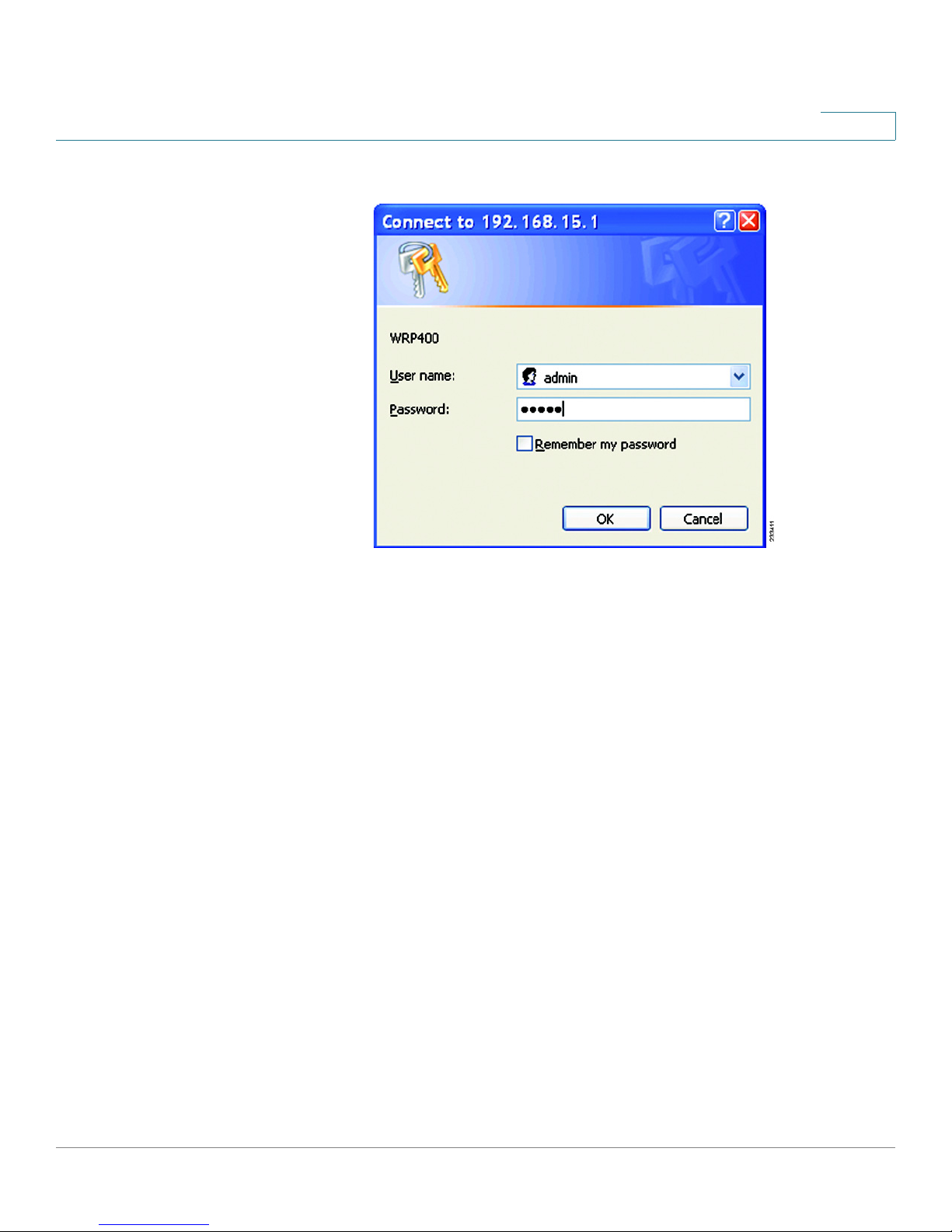
How to Access the Web-Based Utility
To access the web-based utility, launch the web browser on your computer, and
enter the default IP address of the WRP400, 192.168.15.1, in the
Then press Enter.
NOTE If you place the WRP400 behind a primary router with the IP address of
192.168.15.1, then the WRP400 will automatically assume a new default IP address,
192.168.16.1.
When the login screen appears, use the default user name and password, admin.
Then click OK to continue. Later, you can set a new password from the
Administration tab > Management page. See “Administration > Management,”
on page 88.
Address
field.
Cisco WRP400 User Guide 20
Page 23
Using the Web-Based Utility for Advanced Configuration
How to Access the Web-Based Utility
Figure 4 Web-Based Utility Login Window
3
Cisco WRP400 User Guide 21
Page 24

Basic Settings
?
On the Setup screens, you can configure general settings, such as Internet
connection, IP address, DHCP server settings, DDNS, time settings, and advanced
router settings.
4
How Do I...
• Change the Internet Connection type, IP address,
DHCP Server settings, and other basic settings?
See “Setup > Basic Setup,” on page 23.
• Set up DDNS for my web server or FTP server?
See “Setup > DDNS,” on page 34.
• Clone a MAC address to access my Internet service?
See “Setup > MAC Address Clone,” on page 37.
• Change the time settings?
See “Time Setting,” on page 33.
• Configure advanced settings for PPPoE Relay, NAT,
Dynamic Routing (RIP), or Static Routing?
See “Setup > Advanced Routing,” on page 38.
NOTE For information about using the Setup screens to configure mobile network
settings, see Chapter 5, “Installing and Configuring Your Mobile Network.”
Cisco WRP400 User Guide 22
Page 25

Basic Settings
Setup > Basic Setup
Setup > Basic Setup
You can use the Basic Setup page to configure the Internet connection and local
network settings. Complete the following sections of the page:
• Internet Setup
• Network Setup
• Time Setting
NOTE After you enter settings on this page, click Save Settings to apply your changes, or
click Cancel Changes to cancel your changes.
4
Internet Setup
You can use the Internet Setup section to configure the WRP400 for your Internet
connection. Most of the entries in this section require information that you can
obtain from your service provider.
Internet Connection Type
Select the type of Internet connection that your service provider supports:
Automatic Configuration - DHCP
•
• Static IP
• PPPoE
• PPTP
• L2TP
• Te l st ra Ca bl e
Automatic Configuration - DHCP
By default, the Internet Connection Type is set to Automatic Configuration - DHCP,
which should be kept only if your service provider supports DHCP or you are
connecting through a dynamic IP address.
This option usually applies to cable connections.
Cisco WRP400 User Guide 23
Page 26
Basic Settings
Setup > Basic Setup
4
Figure 5 Setup > Basic Setup > Internet Connection Type > Automatic
Configuration - DHCP
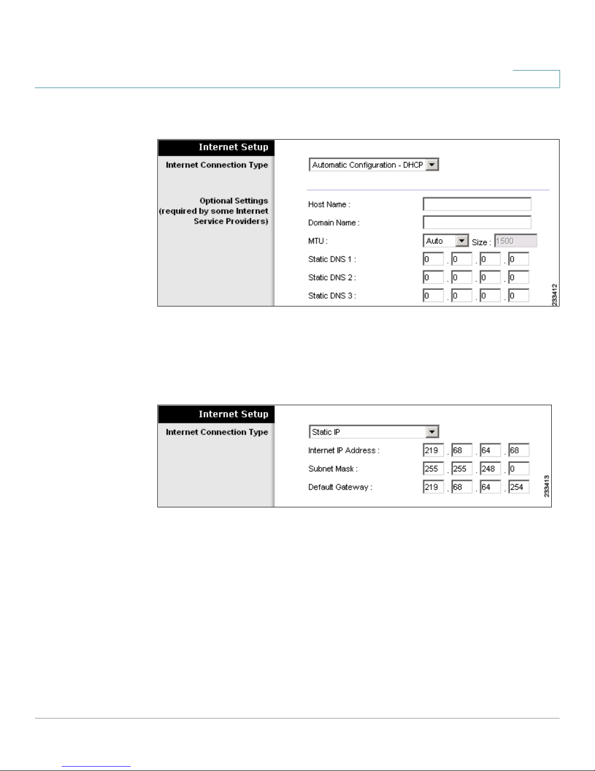
Static IP
If you are required to use a permanent IP address to connect to the Internet, select
Static IP.
Figure 6 Setup > Basic Setup > Internet Connection Type > Static IP
Enter the information that was provided by your service provider.
• Internet IP Address: The IP address of your WRP400, as seen from the
Internet.
• Subnet Mask: The subnet mask, as seen by users on the Internet (including
your service provider).
• Default Gateway: The IP address of your service provider server.
Cisco WRP400 User Guide 24
Page 27
Basic Settings
Setup > Basic Setup
4
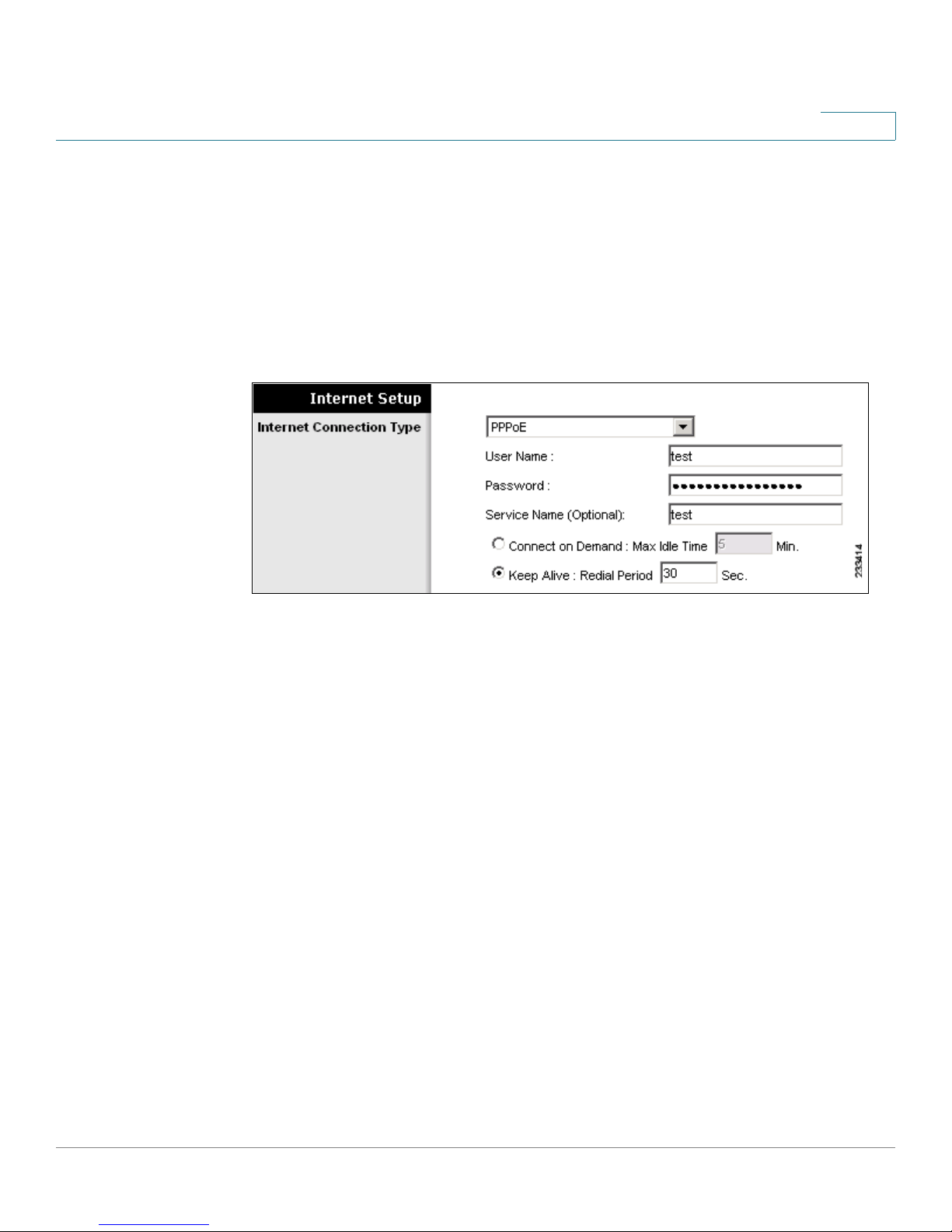
PPPoE
Some DSL-based service providers use PPPoE (Point-to-Point Protocol over
Ethernet) to establish Internet connections. If you are connected to the Internet
through a DSL line, check with your service provider to see if they use PPPoE. If
they do, you will have to enable PPPoE.
This option applies to some DSL services.
Figure 7 Setup > Basic Setup > Internet Connection Type > PPPoE
Enter the information that was provided by your service provider, and select the
Connect On Demand or Keep Alive feature, if desired.
• User Name and Password: The login information for your account.
• Service Name (Optional): The service name (if provided).
• Connect on Demand: Max Idle Time: A feature that allows your WRP400 to
re-establish a terminated connection when a user attempts to access the
Internet. To enable this feature, select Connect on Demand. Use the Max
Idle Time field to specify the period of inactivity that causes a connection to
terminate. Keep the default Max Idle Time of 5 minutes, or specify the
maximum period of inactivity that you want to allow.
• Keep Alive: Redial Period: A feature that allows your WRP400 to check
your Internet connection at a specified interval (Redial Period). If you are
disconnected, then the WRP400 automatically re-establishes your
connection. To enable this option, select Keep Alive. Keep the default Redial
Period of 30 seconds, or specify the interval at which you want the WRP400
to check the Internet connection.
Cisco WRP400 User Guide 25
Page 28
Basic Settings
Setup > Basic Setup
4
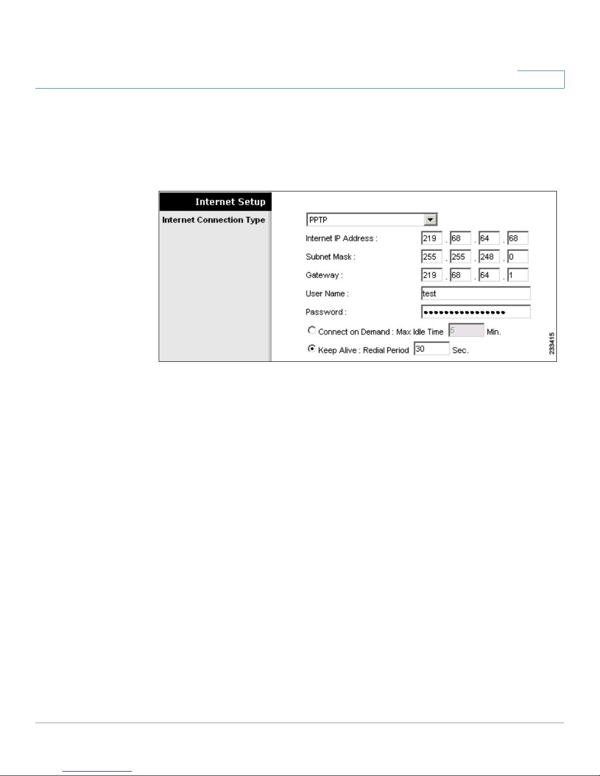
PPTP
Point-to-Point Tunneling Protocol (PPTP) is a service that applies to connections in
Europe only.
Figure 8 Setup > Basic Setup > Internet Connection Type > PPTP
Enter the information that was provided by your service provider, and select the
Connect On Demand or Keep Alive feature, if desired.
• Internet IP Address: The IP address of your WRP400, as seen from the
Internet.
• Subnet Mask: The subnet mask, as seen by users on the Internet (including
your service provider).
• Default Gateway: The IP address of your service provider server.
• User Name and Password: The login information for your account.
• Connect on Demand: Max Idle Time: A feature that allows your WRP400 to
re-establish a terminated connection when a user attempts to access the
Internet. To enable this feature, select Connect on Demand. Use the Max
Idle Time field to specify the period of inactivity that causes a connection to
terminate. Keep the default Max Idle Time of 5 minutes, or specify the
maximum period of inactivity that you want to allow.
• Keep Alive: Redial Period: A feature that allows your WRP400 to check
your Internet connection at a specified interval (Redial Period). If you are
disconnected, then the WRP400 automatically re-establishes your
connection. To enable this option, select Keep Alive. Keep the default Redial
Period of 30 seconds, or specify the interval at which you want the WRP400
to check the Internet connection.
Cisco WRP400 User Guide 26
Page 29

Basic Settings
Setup > Basic Setup
4
L2TP
L2TP is a service that applies to connections in Europe and Israel.
Figure 9 Setup > Basic Setup > Internet Connection Type > L2TP
Enter the information that was provided by your service provider, and select the
Connect On Demand or Keep Alive feature, if desired.
• Server IP Address: The IP address of the L2TP Server.
• User Name and Password: The login information for your account.
• Connect on Demand: Max Idle Time: A feature that allows your WRP400 to
re-establish a terminated connection when a user attempts to access the
Internet. To enable this feature, select Connect on Demand. Use the Max
Idle Time field to specify the period of inactivity that causes a connection to
terminate. Keep the default Max Idle Time of 5 minutes, or specify the
maximum period of inactivity that you want to allow.
• Keep Alive: Redial Period: A feature that allows your WRP400 to check
your Internet connection at a specified interval (Redial Period). If you are
disconnected, then the WRP400 automatically re-establishes your
connection. To enable this option, select Keep Alive. Keep the default Redial
Period of 30 seconds, or specify the interval at which you want the WRP400
to check the Internet connection.
Cisco WRP400 User Guide 27
Page 30
Basic Settings
Setup > Basic Setup
4
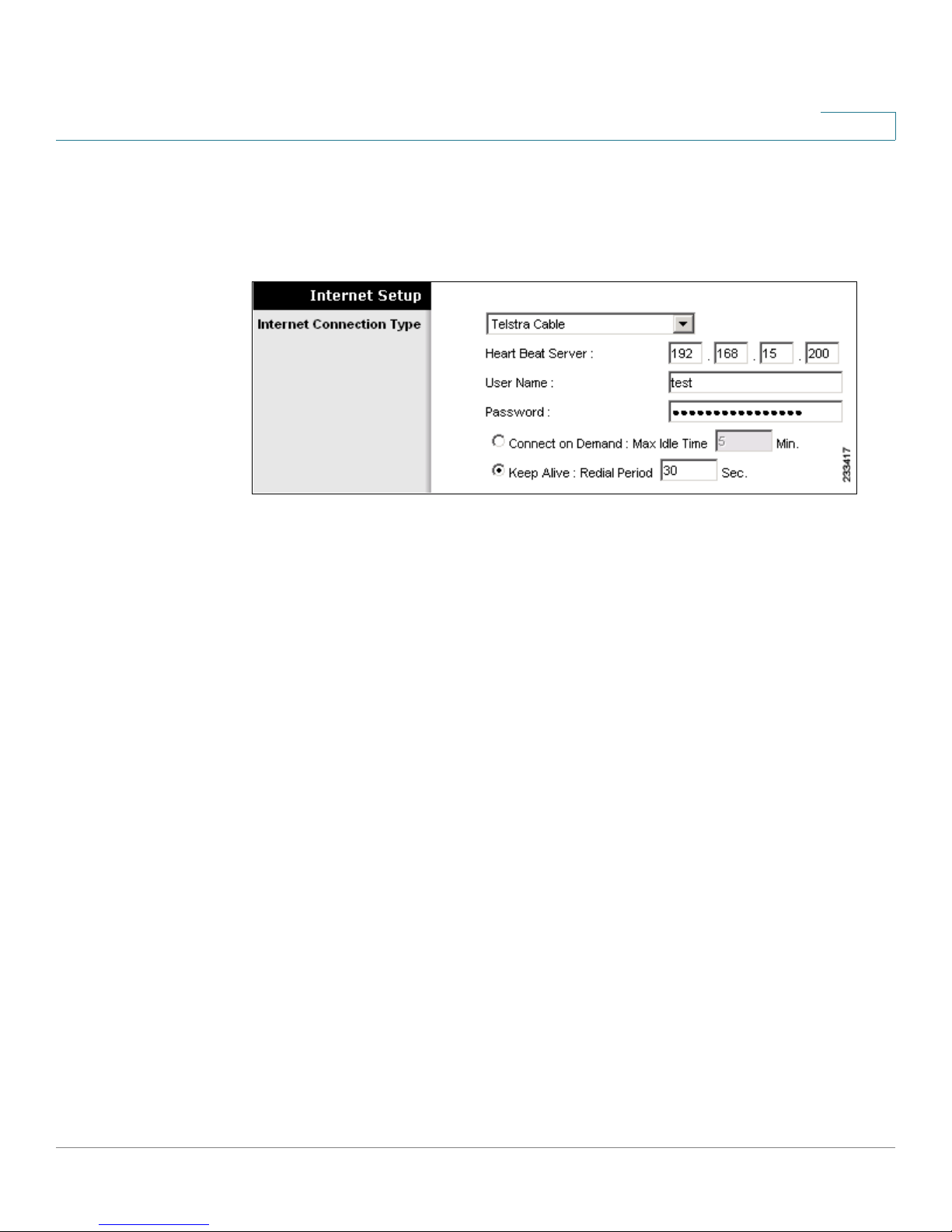
Telstra Cable
Telstra Cable is a service used in Australia only.
Figure10 Setup > Basic Setup > Internet Connection Type > Telstra Cable
Enter the information that was provided by your service provider, and select the
Connect On Demand or Keep Alive feature, if desired.
• Heart Beat Server: The IP address of the Heart Beat Server.
• User Name and Password: The login information for your account.
• Connect on Demand: Max Idle Time: A feature that allows your WRP400 to
re-establish a terminated connection when a user attempts to access the
Internet. To enable this feature, select Connect on Demand. Use the Max
Idle Time field to specify the period of inactivity that causes a connection to
terminate. Keep the default Max Idle Time of 5 minutes, or specify the
maximum period of inactivity that you want to allow.
• Keep Alive: Redial Period: A feature that allows your WRP400 to check
your Internet connection at a specified interval (Redial Period). If you are
disconnected, then the WRP400 automatically re-establishes your
connection. To enable this option, select Keep Alive. Keep the default Redial
Period of 30 seconds, or specify the interval at which you want the WRP400
to check the Internet connection.
Cisco WRP400 User Guide 28
Page 31

Basic Settings
Setup > Basic Setup
4
Optional Settings
Some of these settings may be required by your service provider. Verify with your
service provider before making any changes.
Figure11 Setup > Basic Setup > Optional Settings
• Host Name and Domain Name: A host and domain name for the WRP400.
Some service providers, usually cable service providers, require these
names as identification. In most cases, leaving these fields blank will work.
• MTU: MTU is the Maximum Transmission Unit. The largest packet size that
is permitted for Internet transmission. Select Manual if you want to manually
enter the largest packet size that is transmitted. To have the WRP400 select
the best MTU for your Internet connection, keep the default setting, Auto.
MTU
• Size: When Manual is selected in the
Leave this value in the 576 to 1500 range. The default size depends on the
Internet Connection Type:
- DHCP or Static IP: 1500
- PPPoE: 1492
- PPTP or L2TP: 460
- Tel st r a C ab le : 1500
• Static DNS 1-3: The Domain Name System (DNS) is how the Internet
translates domain or website names into Internet addresses or URLs. Enter
the IP address of the DNS server, which is provided by your service
provider. If you wish to use a different DNS server, enter its IP address in one
of these fields. You can enter up to three DNS server IP addresses here. The
WRP400 will use these for quicker access to functioning DNS servers. By
default, the WRP400 uses 192.168.15.1 for DNS.
field, this option is enabled.
Cisco WRP400 User Guide 29
Page 32

Basic Settings
Setup > Basic Setup
4
Network Setup
You can use the Network Setup section to change the IP address of the WRP400
and configure the DHCP server settings.
NOTE For wireless setup, use the Wireless tab. See Chapter 6, “Configuring Your
Wireless Network.”
Router IP
You can enter the Local IP Address and Subnet Mask of the WRP400, as seen by
your network.
Figure12 Setup > Basic Setup > Network Setup
DHCP Server Setting
You can use these settings to configure the Dynamic Host Configuration Protocol
(DHCP) server function. The WRP400 can be used as a DHCP server for your
network. A DHCP server automatically assigns an IP address to each computer on
your network.
NOTE If you choose to enable the DHCP server option, make sure there is no other DHCP
server on your network.
Cisco WRP400 User Guide 30
Page 33

Basic Settings
Setup > Basic Setup
4
Figure13 Setup > Basic Setup > DHCP Server Setting
• DHCP Server: DHCP is enabled by factory default. If you already have a
DHCP server on your network, or you don’t want a DHCP server, then select
Disabled (no other DHCP features will be available).
• DHCP Reservation: Click this button if you want to reserve IP addresses for
clients. See “DHCP Reservation,” on page 32.
• DNS Proxy: To enable the DNS Proxy feature, select Enabled. To disable the
DNS Proxy feature, keep the default, Disabled.
NOTE The DNS proxy relays DNS requests to the current public network
DNS server for the proxy, and it replies as a DNS resolver to the client
device on the network.
• Starting IP Address: Enter a value for the DHCP server to start with when
issuing IP addresses. The Starting IP Address must be greater than the
default IP address of the WRP400, 192.168.15.1, and less than
192.168.15.253. The default Starting IP Address is 192.168.15.100.
• Maximum DHCP Users: Enter the maximum number of computers that will
receive IP addresses from the DHCP server. This number cannot be greater
than 253. The default is 50.
• IP Address Range: You can view the range of available IP addresses.
• Client Lease Time: Enter the maximum connection time in minutes that a a
dynamic IP address is “leased” to a network user. When the time elapses,
the user is automatically assigned a new dynamic IP address. The default is
0 minutes, which means one day.
Cisco WRP400 User Guide 31
Page 34

Basic Settings
Setup > Basic Setup
4
• Static DNS: Enter the local IP address of the DNS server, which is provided
by your service provider. If you wish to use a different DNS server, enter that
IP address in this field.
NOTE The Domain Name System (DNS) is how the Internet translates
domain or website names into Internet addresses or URLs.
• WINS: If you use a WINS server, enter that server’s IP address here.
Otherwise, when DHCP is enabled, the field is field with the value 0.0.0.0.
NOTE The Windows Internet Naming Service (WINS) manages each PC’s
interaction with the Internet. I
DHCP Reservation
This page appears if you click the DHCP Reservation button on the Basic Setup
page. Use this page to assign a fixed local IP address to a computer on the
network.
Figure 14 DHCP Reservation
Cisco WRP400 User Guide 32
Page 35

Basic Settings
Setup > Basic Setup
4
• Select Clients from DHCP Tables: To reserve an IP address for a client in
the table, check the Select check box, and then click Add Clients.
• Manually Adding Client: To reserve an IP address for a client that is not
listed in the Select Clients table, enter the Client Name, the desired IP
Address, and the client MAC Address in the Manually Adding Client section.
Then click Add.
• Clients Already Reserved: If you want to remove a client from this list, click
Remove.
Click Save Setting to apply your changes, or click Cancel Changes to
cancel your changes. To view the most up-to-date information, click
Refresh. To exit this screen, click Close.
Time Setting
In the Time Setting section of the Basic Setup page, you can choose your time
zone and Time Server Address, if needed.
Figure15 Setup > Basic Setup > Time Setting
• Time Zone: Select the time zone for the location.
• Automatically adjust clock for daylight saving changes: Select this option
if you want the WRP400 to automatically adjust the clock for daylight saving
time. This option is enabled by default.
• Time Server Address: If you want to use the default Network Time Protocol
(NTP) server, keep the default, Auto. If you want to specify the NTP server,
select Manual, and enter the URL or IP address of the NTP server that you
want to use.
• Resync Timer: Enter the number of seconds that elapse before the
WRP400 resyncs with the NTP server. The default is 3600 seconds.
Cisco WRP400 User Guide 33
Page 36

Basic Settings
Setup > DDNS
Setup > DDNS
NOTE After you enter settings on this page, click Save Settings to apply your changes, or
4
You can use the DDNS page to configure the Dynamic Domain Name System
(DDNS) feature. DDNS lets you assign a fixed host and domain name to a dynamic
Internet IP address. It is useful when you are hosting your own website, FTP server,
or other server behind the WRP400.
Before you can use this feature, you need to sign up for DDNS service with a DDNS
service provider, such as www.dyndns.org or www.TZO.com. If you do not want to
use this feature, keep the default setting, Disabled.
click Cancel Changes to cancel your changes.
Choose your DDNS service from the drop-down list, and then enter the
information for your ser vice.
DynDNS.org
Figure16 Setup > DDNS > DynDNS.org
Cisco WRP400 User Guide 34
Page 37

Basic Settings
Setup > DDNS
4
• User Name: Enter the User Name for your DDNS account.
• Password: Enter the Password for your DDNS account.
• Host Name: Enter the DDNS URL assigned by the DDNS service.
• System: Choose the DynDNS service you use: Dynamic, Static, or Custom.
The default selection is Dynamic.
• Mail Exchange (Optional): Enter the address of your mail exchange server,
so emails to your DynDNS address go to your mail server.
• Backup MX: This feature allows the mail exchange server to be a backup.
To enable the feature, select Enabled. To disable this feature, keep the
default, Disabled. If you are not sure which setting to use, keep the default,
Disabled.
• Wildcard: This setting enables or disables wildcards for your host. For
example, if your DDNS address is
wildcards, then
To enable wildcards, select Enabled. To disable wildcards, keep the default,
Disabled. If you are not sure which setting to use, keep the default, Disabled.
x.myplace.dyndns.org
myplace.dyndns.org
will work as well (x is the wildcard).
and you enable
• Internet IP Address: The Internet IP address of the WRP400 is displayed
here. Because it is dynamic, it will change.
• Status: The status of the DDNS service connection is displayed here.
• Update: To manually trigger an update, click this button.
Cisco WRP400 User Guide 35
Page 38

Basic Settings
Setup > DDNS
4
TZO.com
Figure17 Setup > DDNS > TZO.com
• E-mail Address, TZO Key, and Domain Name: Enter the settings for your
account with TZO.
• Internet IP Address: The Internet IP address of the WRP400 is displayed
here. Because it is dynamic, it will change.
• Status: The status of the DDNS service connection is displayed here.
• Update: To manually trigger an update, click this button.
Cisco WRP400 User Guide 36
Page 39

Basic Settings
Setup > MAC Address Clone
Setup > MAC Address Clone
A MAC address is a unique 12-digit code that is assigned to a piece of hardware
for identification. Some service providers require you to register a MAC address in
order to access the Internet. If you previously registered a MAC address with your
service provider for this purpose, you can reassign that MAC address to the
WRP400. In this sense, you are “cloning” the MAC address to be used by this
router.
NOTE After you enter settings on this page, click Save Settings to apply your changes, or
click Cancel Changes to cancel your changes.
Figure18 Setup > MAC Address Clone
4
• Enabled, Disabled: To assign a previously registered MAC address to the
WRP400, select Enabled. Otherwise, select Disabled.
• MAC Address: Enter the MAC address that you previously registered with
your service provider.
• Clone Your PC’s MAC: Click this button to clone the MAC address of the
computer you are using.
Cisco WRP400 User Guide 37
Page 40

Basic Settings
Setup > Advanced Routing
Setup > Advanced Routing
You can use the Advanced Routing page to set up PPPoE Relay, NAT, Dynamic
Routing (RIP), or Static Routing.
NOTE After you enter settings on this page, click Save Settings to apply your changes, or
click Cancel Changes to cancel your changes.
Figure19 Setup > Advanced Routing
4
Cisco WRP400 User Guide 38
Page 41

Basic Settings
Setup > Advanced Routing
4
Advanced Settings: PPPoE Relay
The PPPoE Relay feature enables an L2TP Access Concentrator (LAC) to relay
active discovery and service selection functionality for PPP over Ethernet (PPPoE),
over a Layer 2 Tunneling Protocol (L2TP) control channel, to an L2TP Network
Server (LNS) or tunnel switch (multihop node). The relay functionality of this
feature allows the LNS or tunnel switch to advertise its services to the client,
thereby providing end-to-end control of services between the LNS and a PPPoE
client.
To enable the PPPoE Relay feature for the Internet side, select Enabled. To disable
the PPPoE Relay feature, keep the default, Disabled.
Advanced Routing
Choose the features that you want to enable.
• NAT: If the WRP400 is hosting your network’s connection to the Internet,
keep the default, Enabled. If another router exists on your network, select
Disabled. When the NAT setting is disabled, dynamic routing will be
enabled.
• Dynamic Routing (RIP): This feature enables the WRP400 to automatically
adjust to physical changes in the network’s layout and exchange routing
tables with the other router(s). The WRP400 determines the route of the
network packets based on the fewest number of hops between the source
and the destination. When the NAT setting is enabled, the Dynamic Routing
feature is automatically disabled. When the NAT setting is disabled, this
feature is available. Select Enabled to use the Dynamic Routing feature.
• Static Routing: A static route is a pre-determined pathway that network
information must travel to reach a specific host or network. Enter the
information described below to set up a new static route.
- Route Entries: To set up a static route between the WRP400 and
another network, select a number from the drop-down list. Click Delete
This Entry to delete a static route.
- Enter Route Name: Enter a name for the Route here, using a maximum of
25 alphanumeric characters.
- Destination LAN IP: The Destination LAN IP is the address of the
Cisco WRP400 User Guide 39
remote network or host to which you want to assign a static route.
Page 42

Basic Settings
Setup > Advanced Routing
4
- Subnet Mask: The Subnet Mask determines which portion of a
Destination LAN IP address is the network portion, and which portion is
the host portion.
- Gateway: This is the IP address of the gateway device that allows for
contact between the WRP400 and the remote network or host.
- Interface: This interface tells you whether the Destination LAN IP
address is on the LAN and Wireless (Ethernet and wireless networks) or
the Internet (WAN).
• Show Routing Table: Click this button to view the static routes you have
already set up.
For each route, the Destination LAN IP address, Subnet Mask, Gateway, and
Interface are displayed. Click Refresh to update the information. Click Close
to exit this screen.
Figure 20 Routing Table
Cisco WRP400 User Guide 40
Page 43

?
Installing and Configuring Your Mobile
Network
You can connect a compatible Mobile Broadband USB modem to the USB port of
the WRP400 and configure the mobile network connection.
How Do I...
5
• Connect a USB modem to my WRP400?
See “Installing Your USB Modem,” on page 42
• Enter the account information for my mobile
network connection?
See “Setup > Mobile Network,” on page 43
• Ensure continued Internet access through the
mobile network connection and the Ethernet
connection?
See “Setup > Connection Recovery,” on page 46
• Know when the WRP400 is connected to the
Internet through the mobile network?
See “Understanding the LED Behavior for Mobile
Network,” on page 49
Cisco WRP400 User Guide 41
Page 44

Installing and Configuring Your Mobile Network
Installing Your USB Modem
Installing Your USB Modem
You can install a compatible Mobile Broadband USB Modem into the USB port of
the WRP400 for the purpose of accessing a mobile network.
NOTE For more information about compatible USB devices, visit the WRP400 product page on
Cisco.com: http://www.cisco.com/en/US/products/ps10028/index.html
Connect a compatible USB Modem into the USB port of the WRP400. The Power
LED flashes green and orange, indicating that a device is connected to the USB
port and that initialization is in progress.
After the device initializes, the Power LED shines steady green. If the device fails
to initialize, the LED continues to flash green and orange.
5
By default, the WRP400 connects to the Internet through the local Ethernet, if available. The
mobile network connection is used as a failover when an Ethernet connection is unavailable.
NOTE For more information about configuring your mobile network, see “Setup > Mobile
Network,” on page 43.
Cisco WRP400 User Guide 42
Page 45

Installing and Configuring Your Mobile Network
Setup > Mobile Network
Setup > Mobile Network
You can use this page to choose the connect mode and to enter the settings for
the mobile network. You also can use this page to view the current connection
status.
NOTE After you enter settings on this page, click Save Settings to apply your changes, or
click Cancel Changes to cancel your changes.
Figure 21 Setup > Mobile Network
5
NOTE Ethernet Connection Recovery and Interface Connection Failover will work only if
the Connection Mode is set to Auto. For more information about these features, see
“Setup > Connection Recovery,” on page 46..
Cisco WRP400 User Guide 43
Page 46

Installing and Configuring Your Mobile Network
Setup > Mobile Network
• Connect Mode:
- Select Auto to enable your modem to establish connection
automatically.
- Select Manual to connect or disconnect your modem connection
manually.
- If you change your selection from Auto to Manual, a message appears.
Click OK to acknowledge that Connection Recover will be disabled, or
click Cancel to cancel.
- If you change your selection from Manual to Auto, a message appears.
Click OK to also enable Ethernet Connection Recovery, or click Cancel
to set the Connect Mode to Auto without enabling Ethernet Connection.
• Connect on Demand with Max. Idle Time: You can configure the WRP400
to terminate the Internet connection after it has been inactive for a specified
period of time (Max Idle Time). If your Internet connection has been
terminated due to inactivity, Connect on Demand enables the modem to
automatically re-establish a terminated connection when a user attempts to
access the Internet again. To enable this feature, select Connect on
Demand. In the Max Idle Time field, enter the number of minutes that can
elapse without activity before your Internet connection terminates. The
default Max Idle Time is 5 minutes.
5
• Keep Alive: If you select this option, the WRP400 will periodically check
your Internet connection. If you are disconnected, then the WRP400 will
automatically re-establish your connection.
• Card Status: This field shows the current modem connection status as
Detecting, Connecting, or Connected. If your Connect Mode is Manual, there
will be a button for you to click to connect or disconnect your Modem.
• Configure Mode: Select Auto to allow the WRP400 to automatically detect
which card model was inserted and which carrier is available. Select
Manual to set up the connection manually. To allow the WRP400 to
automatically configure modem & mobile network settings, keep the
default, Auto.
NOTE Some Internet Service Providers (ISPs) will require that you enter
specific information, such as User Name and Password. This
information can be obtained from your ISP, if required.
Cisco WRP400 User Guide 44
Page 47

Installing and Configuring Your Mobile Network
Setup > Mobile Network
• Card Model: The data card model that is inserted in the USB port.
• Carrier: The mobile network service provider for Internet connection. This
setting is required when you are using HSDPA/UMTS/GPRS Internet
service.
• Country: Select the card issue country from the first drop-down menu.
• Carrier: Select the card issue provider from the second drop-down menu.
• Access Point Name (APN): The Internet network to which the mobile
device is connecting to. Enter the Access Point Name provided by your
mobile network service provider.
• Dial Number: The dial number for the Internet connection. Enter the Dial
Number provided by your mobile network service provider.
• Optional Settings: Some of these settings may be required by your mobile
network service provider. Verify with your mobile network service provider
before making any changes.
5
• User Name and Password (Optional): Enter the User Name provided by
your mobile network service provider.
• SIM PIN (Optional): The PIN code associated with your SIM card. Enter
your SIM PIN number here.
• Server Name (Optional): The name of the server for the Internet
connection.
• Authentication: The type of authentication used by your service provider.
Select your authentication type, if you do not know which type to use, keep
the default setting, Auto.
• Service Type: Select the most commonly available type of mobile data
service connection based on your area service signal. If your location
supports only one mobile data service, you may set up for enhance build up
connection. The first selection will always search for HSPDA/3G/UMTS
service or switch to GPRS automatically only when it is available.
Cisco WRP400 User Guide 45
Page 48

Installing and Configuring Your Mobile Network
Setup > Connection Recovery
Setup > Connection Recovery
An Internet connection can be established via the Ethernet Internet port or a USB
modem connected to the USB port. While both Ethernet and USB interfaces may
be connected, only one of them can be used to establish a link at a time.
By default, the WRP400 uses the Ethernet Internet connection when available. If
the Ethernet Internet connection fails, the WRP400 automatically attempts to bring
up another connection on another interface. This feature is called failover.
Whenever the Ethernet Internet connection recovers, the WRP400 automatically
attempts to bring back and recover the Ethernet Internet connection. This feature
is called Recovery.
NOTE After you enter settings on this page, click Save Settings to apply your changes, or
click Cancel Changes to cancel your changes.
5
Figure 22 Setup > Connection Recovery
Cisco WRP400 User Guide 46
Page 49

Installing and Configuring Your Mobile Network
Setup > Connection Recovery
Recovery & Failover
• Ethernet Connection Recovery: This feature ensures that your Internet
connection is made through the Ethernet interface if it is available. Enabling
this feature also enables the Interface Connection Failover, which ensures
that if the Internet connection fails on the Ethernet interface, the WRP400
automatically attempts to bring up the connection through the mobile
network if available. Whenever the Ethernet Internet connection recovers,
the WRP400 automatically attempts to bring back and recover the Ethernet
Internet connection.
NOTE Ethernet Connection Recovery requires that your Mobile Connection
Mode is set to Auto and your Ethernet interface is set to the high
priority. When you enable this feature, a message appears. Click OK
to confirm that you want to change the Mobile Connection Mode and
the Ethernet interface priority.
5
• Interface Connection Failover: Failover detection works by detecting the
physical connection and/or presence of traffic on the Internet link. If the link
is idle for some time, the WRP400 will attempt to ping a destination. If the
ping does not reply, the WRP400 assumes the link is down and attempts to
fail over to another interface. Click Enabled if you want to use this feature, or
otherwise click Disabled. This feature is automatically enabled if you enable
Ethernet Connection Recovery.
• Timeout: Specify the time interval at which the WRP400 detects the status
of the Internet connection. The default timeout interval is 60 seconds.
• Failover Validation Site: A ping target for the WRP400 to use to detect the
status of the Internet connection. By default the WRP400 pings the Network
Time Protocol (NTP) servers. You may specify a different IP address as a
target here.
Cisco WRP400 User Guide 47
Page 50

Installing and Configuring Your Mobile Network
Setup > Connection Recovery
WAN Interfaces
The Summary table includes one row of information for the Ethernet interface and
one row of information for the USB interface.
• Status: The link status of this interface:
- Disconnected: The device is plugged in and available but not active.
- Connecting: The WRP400 is attempting to bring up the link over the
device.
- Connected: The link is up and running on the device.
- Wait Recovery: When the WRP400 is connected to the Ethernet, this
status means that the Ethernet is waiting recovered to route to the
Failover Validation Site.
5
NOTE You can click the Status hyperlink to view the Status page for the
interface. To return to the Connection Recovery screen, click the Back
button on the browser toolbar. For more information, see“Router
Information,” on page 102 and “Mobile Network Status,” on
page 104 .
• Priority: The priority setting determines which interface is used when both
interfaces are available. By default, the Ethernet interface has top priority.
However, you can change the priority setting by clicking Up to move an
interface to the top priority level or by clicking Down to move an interface to
the low priority level.
NOTE The interface priority setting is configurable only when Ethernet
Connection Recovery is disabled.
Cisco WRP400 User Guide 48
Page 51

Installing and Configuring Your Mobile Network
Understanding the LED Behavior for Mobile Network
Understanding the LED Behavior for Mobile Network
The Internet LED indicates connectivity to the Internet through the Ethernet
connection only. The Power LED indicates the progress of USB initialization or the
status of the mobile network connection.
LED Behavior During USB Modem Installation
The Power LED indicates the progress of the initialization.
• Before you connect the USB modem, the Power LED shines steady green to
show that the WRP400 has power.
• After you connect the USB modem, the Power LED flashes green and
orange to show that a device is connected to the USB port and that
initialization is in progress.
5
• If the initialization is successful, the Power LED shines steady green. If the
initialization fails, the LED continues to flash green and orange.
By default, the WRP400 connects to the Internet through the wired Ethernet, if
available. The mobile network connection is used as a failover when an Ethernet
connection is unavailable.
LED Behavior During Mobile Network Connectivity
After you successfully install a USB modem, the Power LED indicates the status of
the mobile network connection:
• Flashing Orange: The WRP400 is attempting to connect to the Internet
through the mobile network connection.
• Steady Orange: The WRP400 is connected to the Internet through the
mobile network connection.
• Continuous Flashing Orange: The WRP400 failed to connect to the Internet
through the mobile network connection and is trying again.
• Steady Green:
- If a USB device is connected, this LED behavior indicates that the device
Cisco WRP400 User Guide 49
was successfully initialized and that the WRP400 is not using the mobile
network connection. If an Internet connection is active through the
Ethernet, then the Internet LED is illuminated.
Page 52

Installing and Configuring Your Mobile Network
Understanding the LED Behavior for Mobile Network
- If the USB device was removed, this LED behavior indicates that the
WRP400 has power.
To check the status of the USB Modem, or modify the settings for the mobile
network, connection recovery, and failover, you can use the administration web
server.
5
Cisco WRP400 User Guide 50
Page 53

?
Configuring Your Wireless Network
You can use the Wireless screens to set up and secure your wireless network.
How Do I...
• Set up my wireless network?
See “Wireless > Basic Wireless Settings,” on
page 51.
6
• Secure my wireless network?
See “Wireless > Wireless Security,” on page 56.
• Specify computers that can or cannot access my
network?
See “Wireless > Wireless MAC Filter,” on page 62
• Configure special router functions for my wireless
network?
See “Wireless > Advanced Wireless Settings,” on
page 64.
Wireless > Basic Wireless Settings
You can use the Basic Wireless Settings page to configure your wireless network
manually or to use Wi-Fi Protected Setup.
Figure 23 Wireless > Basic Wireless Settings > Wireless Configuration
Cisco WRP400 User Guide 51
Page 54

Configuring Your Wireless Network
Wireless > Basic Wireless Settings
The options on the page change after you choose Manual or Wi-Fi Protected
Setup.
• Choose Manual if you want to manually configure your network, if you are
setting up your secondary network (SSID2), of if you do not have client
devices that support Wi-Fi Protected Setup. See “Manual Configuration of
the Network,” on page 52.
• Choose Wi-Fi Protected Setup if you have client devices, such as wireless
adapters, that support Wi-Fi Protected Setup. For more information, see
“Wi-Fi Protected Setup,” on page 54.
Manual Configuration of the Network
After you choose Manual for the Wireless Configuration method, additional fields
appear. You can change the SSID of the wireless network and enable a second
network, or guest network.
6
Figure 24 Wireless > Basic Wireless Settings > Manual Configuration
• Network Mode: Select the wireless standards that are running on your
network. If you have Wireless-G and Wireless-B devices, keep the default
setting, Mixed. If you have only Wireless-G devices, select Wireless-G only.
If you have only Wireless-B devices, select Wireless-B only.
• Wireless Channel: Select the channel that you want to use. To allow the
WRP400 to select the best available wireless channel, keep the default,
Auto.
Cisco WRP400 User Guide 52
Page 55

Configuring Your Wireless Network
Wireless > Basic Wireless Settings
• SSID1, SSID2: The SSID is the network name shared among all devices in a
wireless network. The WRP400 can support up to two wireless networks.
By default, one wireless network is enabled, and you can create a second
wireless network.
Configure the following settings for each wireless network:
- Wireless Network Name (SSID): The default wireless network uses
this name: “cisco” followed by the last four digits of the wireless MAC
address of the WRP400. To rename the default wireless network, enter a
unique Wireless Network Name, which is case-sensitive and must not
exceed 32 characters. You can use any of the characters on the
keyboard. To create a second wireless network, select Network Enabled
for the SSID2 setting. Then enter a unique Wireless Network Name.
6
NOTE If you are unable to configure the SSID2 settings, contact your service
provider for more information.
- SSID Broadcast Enabled: When wireless clients survey the local area
for wireless networks, they detect the SSID broadcast by the WRP400. If
you want to broadcast the SSID, keep the check box selected. If you do
not want to broadcast the SSID, deselect the check box.
- For Internet Access Only: On your second wireless network (SSID2),
you can set up guest access, which allows access to the Internet while
blocking access to your local network. For example, a guest cannot
access the data stored on your local computers. To limit guests to
Internet access only, keep the check box selected. To allow local
network access, deselect the check box.
NOTE The For Internet Access Only feature applies only to SSID2.
- Network Enabled: To enable the wireless network, select the check
box. To disable the wireless network, deselect the check box.
Cisco WRP400 User Guide 53
Page 56

Configuring Your Wireless Network
Wireless > Basic Wireless Settings
Wi-Fi Protected Setup
After you choose Wi-Fi Protected Setup for the Wireless Configuration, the
instructions, fields, and buttons appear on the screen. Three setup methods are
available.
NOTE Wi-Fi Protected Setup is available for your primary wireless network
- Method #1: To configure a client device that has a Wi-Fi Protected
Setup button, click or press the Wi-Fi Protected Setup button on the
client device. Then click the button shown on the screen. After the client
device has been configured, click OK. Then refer to your client device or
its documentation for further instructions. Repeat for any additional
devices that you need to configure.
6
(SSID1) only. To configure your second wireless network (SSID2),
select Manual. If you are unable to configure the second wireless
network, contact your service provider for more information (these
settings may be controlled by your service provider).
- Method #2: To configure a client device that has a Wi-Fi Protected
Setup PIN number, enter the PIN number in the
Register. After the client device has been configured, click OK. Then
refer to your client device or its documentation for further instructions.
Repeat for any additional devices that you need to configure.
- Method #3: If your client device asks for the PIN number of the WRP400,
enter the PIN number that is shown on the screen. This number also
appears on the label on the bottom of the WRP400. After the client
device has been configured, click OK. Then refer to your client device or
its documentation for further instructions. Repeat for any additional
devices that you need to configure.
field on this screen. Click
Cisco WRP400 User Guide 54
Page 57

Configuring Your Wireless Network
Wireless > Basic Wireless Settings
6
Cisco WRP400 User Guide 55
Page 58

Configuring Your Wireless Network
Wireless > Wireless Security
Wireless > Wireless Security
You can use the Wireless Security page to configure the security of your wireless
network(s). The WRP400 supports the following wireless security mode options:
WPA Personal, WPA Enterprise, WPA2 Personal, WPA2 Enterprise, and WEP.
WEP (Wired Equivalent Privacy) is an older security standard. WPA (Wi-Fi
Protected Access) is a newer security standard that is stronger than WEP
encryption. A network encrypted with WPA/WPA2 is more secure than a network
encrypted with WEP, because WPA/WPA2 uses dynamic key encryption. To
protect the information as it passes over the airwaves, you should enable the
highest level of encryption supported by your network equipment.
These options are briefly discussed here. For additional guidelines, refer to
Chapter 2, “Before You Begin: Understanding Wireless Security.”
6
NOTE If you used Wi-Fi Protected Setup to configure your wireless network(s), then
wireless security has already been set up for your primary wireless network. Do
not make changes to the Wireless Security screen for your primary wireless
network.
NOTE After you enter settings on this page, click Save Settings to apply your changes, or
click Cancel Changes to cancel your changes.
Select the SSID that you want to configure. Then choose the Security Mode. If you
do not want to use wireless security, keep the default, Disabled.
Figure 25 Wireless > Wireless Security
Cisco WRP400 User Guide 56
Page 59

Configuring Your Wireless Network
Wireless > Wireless Security
NOTE If you enabled the second wireless network on the Basic Wireless Settings screen,
you will need to set up wireless security for each SSID.
Depending on the selected Security Mode, additional fields appear.
WEP
WEP is a basic encryption method, which is not as secure as WPA
Figure 26 Wireless Security > WEP
6
• Encryption: Select a level of WEP encryption, 64 bits 10 hex digits or 28
bits 26 hex digits. The default is 64 bits 10 hex digits.
• Passphrase: Enter a Passphrase to automatically generate WEP keys. Then
click Generate.
• Key 1-4: If you did not enter a Passphrase, enter the WEP key(s) manually.
• TX Key: Select which TX (Transmit) Key to use. The default is 1.
Cisco WRP400 User Guide 57
Page 60

Configuring Your Wireless Network
Wireless > Wireless Security
WPA Personal
Wi-Fi Protected Access (WPA) is a security mode that uses a shared key to restrict
access to authorized users.
NOTE If you are using WPA, always remember that each device in your wireless network
MUST use the same WPA method and shared key, or else the network will not
function properly.
Figure 27 Wireless Security > WPA Personal
6
• WPA Algorithms: WPA supports two encryption methods, TKIP and AES,
with dynamic encryption keys. Select the type of algorithm, TKIP or AES.
The default is TKIP.
• WPA Shared Key: Enter a WPA Shared Key of 8-63 characters.
• Group Key Renewal: Enter a Group Key Renewal period, which instructs
the WRP400 how often it should change the encryption keys. The default is
3600 seconds.
Cisco WRP400 User Guide 58
Page 61

Configuring Your Wireless Network
Wireless > Wireless Security
WPA2 Personal
Like WPA Personal, WPA2 Personal uses a shared key to restrict access to your
wireless network. WPA2 can combine TKIP and AES encryption.
Figure 28 Wireless Security > WPA2 Personal
6
• WPA Algorithms: WPA2 supports two encryption methods, TKIP and AES,
with dynamic encryption keys. Select the type of algorithm, AES or TKIP +
AES. The default is TKIP + AES.
• WPA Shared Key: Enter a WPA Shared Key of 8-63 characters.
• Group Key Renewal: Enter a Group Key Renewal period, which instructs
the WRP400 how often it should change the encryption keys. The default is
3600 seconds.
Cisco WRP400 User Guide 59
Page 62

Configuring Your Wireless Network
Wireless > Wireless Security
WPA Enterprise
This option features WPA used in coordination with a RADIUS (Remote
Authentication Dial-In User Service) server. This option should only be used when
a RADIUS server is connected to the WRP400.
Figure 29 Wireless Security > WPA Enterprise
6
• WPA Algorithms: WPA supports two encryption methods, TKIP and AES,
with dynamic encryption keys. Select the type of algorithm, TKIP or AES.
The default is TKIP.
• RADIUS Server Address: Enter the IP address of the RADIUS server.
• RADIUS Port: Enter the port number of the RADIUS server. The default
value is 1812.
• Shared Key: Enter the key shared between the WRP400 and the server.
• Key Renewal Timeout: Enter a Key Renewal Timeout period, which
instructs the WRP400 how often it should change the encryption keys. The
default is 600 seconds.
Cisco WRP400 User Guide 60
Page 63

Configuring Your Wireless Network
Wireless > Wireless Security
WPA2 Enterprise
This option features WPA2 used in coordination with a RADIUS (Remote
Authentication Dial-In User Service) server. This option should only be used when
a RADIUS server is connected to the WRP400.
Figure 30 Wireless > Wireless Security > WPA2Enterprise
6
• WPA Algorithms: WPA2 supports two encryption methods, TKIP and AES,
with dynamic encryption keys. Select the type of algorithm, AES or TKIP +
AES. The default is TKIP + AES.
• RADIUS Server Address: Enter the IP address of the RADIUS server.
• RADIUS Port: Enter the port number of the RADIUS server. The default
value is 1812.
• Shared Key: Enter the key shared between the WRP400 and the server.
• Key Renewal Timeout: Enter a Key Renewal Timeout period, which
instructs the WRP400 how often it should change the encryption keys. The
default is 600 seconds.
Cisco WRP400 User Guide 61
Page 64

Configuring Your Wireless Network
Wireless > Wireless MAC Filter
Wireless > Wireless MAC Filter
Wireless access can be filtered by using the MAC addresses of the wireless
devices within your network’s radius.
NOTE After you enter settings on this page, click Save Settings to apply your changes, or
click Cancel Changes to cancel your changes.
Figure 31 Wireless > Wireless MAC Filter
6
• Select a SSID: Select the SSID that you want to configure.
NOTE If you enabled the second wireless network on the Basic Wireless
Cisco WRP400 User Guide 62
Settings screen, then you can set up wireless MAC filtering for each
SSID.
Page 65

Configuring Your Wireless Network
Wireless > Wireless MAC Filter
• Wireless MAC Filter: To filter wireless users by MAC address, select
Enabled If you do not wish to filter users by MAC address, keep the default
setting, Disabled.
Access Restriction
In this section, you choose how to use the MAC Address Filter List: to prevent
access or to permit access.
• Prevent: Select this option to block wireless access to devices with the
specified MAC addresses. This button is selected by default.
• Permit: Select this to allow wireless access by devices with the specified
MAC addresses.
MAC Address Filter List
6
In this section, you identify the clients to filter. You can choose clients from the
Wireless Client List, or you can enter the MAC addresses individually.
• Wireless Client List: Click this button if you want to choose the clients from
the Wireless Client List screen. See “Wireless Client List.” below.
• MAC 01-40: Enter the MAC addresses of the devices whose wireless
access you want to block or allow.
Wireless Client List
Check the Save to MAC Address Filter List check box to select a device. Then
click Add to add the device to the MAC Address Filter List.
To retrieve the most up-to-date information, click Refresh. To exit this screen and
return to the Wireless MAC Filter screen, click Close.
Cisco WRP400 User Guide 63
Page 66

Configuring Your Wireless Network
Wireless > Advanced Wireless Settings
Figure 32 Wireless Client List
6
Wireless > Advanced Wireless Settings
The Advanced Wireless Settings screen is used to set up the advanced wireless
functions of the WRP400. These settings should only be adjusted by an expert
administrator as incorrect settings can reduce wireless performance.
NOTE After you enter settings on this page, click Save Settings to apply your changes, or
click Cancel Changes to cancel your changes.
Figure 33 Wireless > Advanced Wireless Settings
Cisco WRP400 User Guide 64
Page 67

Configuring Your Wireless Network
Wireless > Advanced Wireless Settings
• Authentication Type: The default is set to Auto, which allows either Open
System or Shared Key authentication to be used. With Open System
authentication, the sender and the recipient do not use a WEP key for
authentication. With Shared Key authentication, the sender and recipient
use a WEP key for authentication. Select Shared Key to only use Shared
Key authentication.
• Transmission Rate: The rate of data transmission should be set depending
on the speed of your wireless network(s). You can select from a range of
transmission speeds, or you can select Auto to have the WRP400
automatically use the fastest possible data rate and enable the AutoFallback feature. Auto-Fallback will negotiate the best possible connection
speed between the WRP400 and a wireless client. The default is Auto.
• CTS Protection Mode: The WRP400 will automatically use CTS (Clear-To-
Send) Protection Mode when your Wireless-G products are experiencing
severe problems and are not able to transmit to the WRP400 in an
environment with heavy 802.11b traffic. This function boosts the ability of
the WRP400 to catch all Wireless-G transmissions but will severely
decrease performance. The default is Auto.
6
• Beacon Interval: Enter a value between 1 and 65,535 milliseconds. The
Beacon Interval value indicates the frequency interval of the beacon. A
beacon is a packet broadcast by the WRP400 to synchronize the wireless
network(s). The default value is 100.
• DTIM Interval: This value, between 1 and 255, indicates the interval of the
Delivery Traffic Indication Message (DTIM). A DTIM field is a countdown
field informing clients of the next window for listening to broadcast and
multicast messages. When the WRP400 has buffered broadcast or
multicast messages for associated clients, it sends the next DTIM with a
DTIM Interval value. Its clients hear the beacons and awaken to receive the
broadcast and multicast messages. The default value is 1.
• RTS Threshold: If you encounter inconsistent data flow, only minor
reduction of the default value, 2347, is recommended. If a network packet is
smaller than the preset RTS threshold size, the RTS/CTS mechanism will
not be enabled. The WRP400 sends Request to Send (RTS) frames to a
particular receiving station and negotiates the sending of a data frame.
After receiving an RTS, the wireless station responds with a Clear to Send
(CTS) frame to acknowledge the right to begin transmission. The RTS
Threshold value should remain at its default value of 2347.
Cisco WRP400 User Guide 65
Page 68

?
7
Configuring Network Security and Controlling
Internet Access
You can use the Security screens to enable a firewall, add filters, or allow VPN
tunnels. You can use the Access Restrictions screen to control Internet usage.
How Do I...
Security > Firewall
The Firewall screen is used to configure a firewall that can filter out various types
of unwanted traffic on the local network.
NOTE After you enter settings on this page, click Save Settings to apply your changes, or
click Cancel Changes to cancel your changes.
• Enable a firewall, Internet filters, or Web filters?
See “Security > Firewall,” on page 66
• Allow VPN tunnels to pass through the firewall?
See “Security > VPN Passthrough,” on page 68
• Block or allow specific types of Internet usage and
traffic?
See “Access Restrictions > Internet Access,” on
page 69.
Cisco WRP400 User Guide 66
Page 69

Configuring Network Security and Controlling Internet Access
Security > Firewall
Figure 34 Security > Firewall
7
Firewall
• SPI Firewall Protection: To use firewall protection, keep the default,
Enabled. To turn off firewall protection, select Disabled.
Internet Filter
• Filter Anonymous Internet Requests: This feature makes it more difficult for
outside users to work their way into your network. This feature is selected
by default. Deselect the feature to allow anonymous Internet requests.
• Filter Internet NAT Redirection: This feature uses port forwarding to block
access to local servers from local networked computers. Select this feature
to filter Internet NAT redirection. It is not selected by default.
• Filter IDENT (Port 113): This feature keeps port 113 from being scanned
by devices outside of your local network. This feature is selected by
default. Deselect this feature to disable it.
Cisco WRP400 User Guide 67
Page 70

Configuring Network Security and Controlling Internet Access
Security > VPN Passthrough
Web Filter
• Proxy: Use of WAN proxy servers may compromise the security of the
WRP400. Denying Proxy will disable access to any WAN proxy servers.
Select this feature to enable proxy filtering. Deselect the feature to allow
proxy access.
• Java: Java is a programming language for websites. If you deny Java, you
run the risk of not having access to Internet sites created using this
programming language. Select this feature to enable Java filtering. Deselect
the feature to allow Java usage.
• ActiveX: ActiveX is a programming language for websites. If you deny
ActiveX, you run the risk of not having access to Internet sites created using
this programming language. Select this feature to enable ActiveX filtering.
Deselect the feature to allow ActiveX usage.
7
• Cookies: A cookie is data stored on your computer and used by Internet
sites when you interact with them. Select this feature to filter cookies.
Deselect the feature to allow cookie usage.
Security > VPN Passthrough
The VPN Passthrough screen allows you to enable VPN tunnels using IPSec, PPTP,
or L2TP protocols to pass through the firewall of the WRP400.
NOTE After you enter settings on this page, click Save Settings to apply your changes, or
click Cancel Changes to cancel your changes.
Figure 35 Security > VPN Passthrough
Cisco WRP400 User Guide 68
Page 71

Configuring Network Security and Controlling Internet Access
Access Restrictions > Internet Access
• IPSec Passthrough: Internet Protocol Security (IPSec) is a suite of protocols
used to implement secure exchange of packets at the IP layer. To allow IPSec
tunnels to pass through the WRP400, keep the default, Enabled.
• PPTP: Passthrough Point-to-Point Tunneling Protocol (PPTP) allows the
Point-to-Point Protocol (PPP) to be tunneled through an IP network. To allow
PPTP tunnels to pass through the WRP400, keep the default, Enabled.
• L2TP Passthrough: Layer 2 Tunneling Protocol is the method used to
enable Point-to-Point sessions via the Internet on the Layer 2 level. To allow
L2TP tunnels to pass through the WRP400, keep the default, Enabled.
Access Restrictions > Internet Access
You can use the Internet Access Policy screen to block or allow specific kinds of
Internet usage and traffic, such as Internet access, designated services, and
websites during specific days and times.
7
NOTE After you enter settings on this page, click Save Settings to apply your changes, or
click Cancel Changes to cancel your changes.
Cisco WRP400 User Guide 69
Page 72

Configuring Network Security and Controlling Internet Access
Access Restrictions > Internet Access
Figure 36 Access Restrictions > Internet Access
7
• Access Policy: Select a policy from the drop-down list to display that
policy’s settings. You can then enter or modify the settings. Be sure to save
your changes before selecting another policy from the drop-down list.
Cisco WRP400 User Guide 70
Page 73

Configuring Network Security and Controlling Internet Access
Access Restrictions > Internet Access
• Delete This Entry: To delete an access policy, select the policy’s number
from the Access Policy list, and then click this button.
• Summary: To view all policies, click this button. The Summary appears in a
separate window. The policies are listed with the following information: No.
(number), Policy Name, Access, Days, Time of Day, and status (Enabled). To
enable a policy, check Enabled. To delete a policy, click Delete. Click Save
Settings to save your changes, or click Cancel Changes to cancel your
changes. To return to the Internet Access Policy screen, click Close.
7
• Enter Policy Name: Enter a name for the policy that you selected in the
Access Policy list.
• Status: Policies are disabled by default. To enable the selected policy,
select Enabled.
Cisco WRP400 User Guide 71
Page 74

Configuring Network Security and Controlling Internet Access
Access Restrictions > Internet Access
• Applied PCs: Click Edit List to select the computers that will be affected by
the policy that you selected in the Access Policy list. The List of PCs window
appears.
7
Choose the PCs that will be affected by this policy:
- MAC Address: Enter a MAC address that you want to add to the list.
- IP Address: Enter the final octet of an IP address that you want to add to
the list.
- IP Address Range: Enter the final octet of an IP address in the first box,
and then enter the final octet of another IP address in the second box, to
create a range of IP addresses to add to the list.
Click Save Settings to save your changes, or click Cancel Changes to
cancel your changes. To return to the Internet Access Policy screen, click
Close.
• Access Restriction: Select the appropriate option, Deny or Allow,
depending on whether you want to block or allow Internet access for the
computers that are listed on the List of PCs screen.
Cisco WRP400 User Guide 72
Page 75

Configuring Network Security and Controlling Internet Access
Access Restrictions > Internet Access
• Schedule: Decide which days and what times you want the selected policy
to be enforced. Select the individual days during which the policy will be in
effect, or select Everyday. Then enter a range of hours and minutes during
which the policy will be in effect, or select 24 Hours.
• Website Blocking by URL Address: You can block websites with specific
URL addresses. Enter each URL in a separate URL field.
• Website Blocking by Keyword: You can block websites using specific
keywords. Enter each keyword in a separate Keyword field.
• Blocked Applications: You can filter access to various services accessed
over the Internet, such as FTP or telnet. You can block up to three
applications per policy.
- From the Application list, select the application you want to block. Then
click the >> button to move it to the Blocked List. To remove an
application from the Blocked List, select it and click the << button.
7
- If the application you want to block is not listed or you want to edit a
service’s settings, enter the application’s name in the Application Name
field. Enter its range in the Port Range fields. Select its protocol from the
Protocol drop-down menu. Then click Add.
- To modify a service, select it from the Application list. Change its name,
port range, and/or protocol setting. Then click Modify.
- To delete a service, select it from the Application list. Then click Delete.
Creating or Modifying an Internet Access Policy
Follow this procedure to create or modify an Internet Access Policy.
STEP 1 Select a number from the Access Policy drop-down menu.
STEP 2 Enter a name in the Policy Name field.
STEP 3 To enable this policy, select Enabled.
STEP 4 Click Edit List to select the computers that will be affected by this policy.
a. In the List of PCs window, enter individual MAC addresses or IP addresses, or
enter IP address ranges.
b. Click Save Settings to apply your changes, or click Cancel Changes to cancel
your changes. Then click Close close the window.
Cisco WRP400 User Guide 73
Page 76

Configuring Network Security and Controlling Internet Access
Access Restrictions > Internet Access
STEP 5 In the Access Restriction section, choose to Deny Internet access or to Allow
Internet access for the computers that you listed on the List of PCs screen.
STEP 6 In the Schedule section, select the days and times when this policy applies, as
described above.
STEP 7 In the remaining sections of the page, enter the URLs, keywords, and applications
that you want to block with this policy, as described above.
STEP 8 Click Save Settings to save the settings. To cancel the settings, click Cancel
Changes.
STEP 9 Repeat these steps to create additional policies, one at a time.
7
Cisco WRP400 User Guide 74
Page 77

?
Configuring Applications and Gaming
You can use the Applications and Gaming screens to configure your WRP400 to
support applications, services, and gaming.
How Do I...
• Customize port services for common applications?
See “Applications and Gaming > Single Port
Forwarding,” on page 76.
8
• Support public services such as web servers, FTP
servers, e-mail servers, and Internet gaming?
See “Applications and Gaming > Port Range
Forward,” on page 77.
• Specify the ports that are opened for specific
applications?
See “Applications & Gaming > Port Range
Triggering,” on page 79.
• Specify one computer to be exposed to the Internet
for public services?
See “Applications and Gaming > DMZ,” on page 80
• Prioritize service for real-time applications such as
video-conferencing?
See “Applications and Gaming > QoS,” on page 81.
Cisco WRP400 User Guide 75
Page 78

Configuring Applications and Gaming
Applications and Gaming > Single Port Forwarding
Applications and Gaming > Single Port Forwarding
The Single Port Forwarding screen allows you to customize port services for
common applications on this screen.
When users send these types of requests to your network via the Internet, the
WRP400 will forward those requests to the appropriate servers (computers).
Before using forwarding, you should assign static IP addresses to the designated
servers (use the DHCP Reservation feature on the Basic Setup screen). See
“DHCP Reservation,” on page 32.
NOTE After you enter settings on this page, click Save Settings to apply your changes, or
click Cancel Changes to cancel your changes.
8
Figure 37 Applications and Gaming > Single Port Forwarding
Common applications are available for the first five entries. Select the appropriate
application. Then enter the IP address of the server that should receive these
requests. Select Enabled to activate this entry.
Cisco WRP400 User Guide 76
Page 79

Configuring Applications and Gaming
Applications and Gaming > Port Range Forward
For additional applications, complete the following fields:
• Application Name: Enter the name you wish to give the application. Each
name can be up to 12 characters.
• External Port: Enter the external port number used by the server or Internet
application. Check with the Internet application documentation for more
information.
• Internal Port: Enter the internal port number used by the server or Internet
application. Check with the Internet application documentation for more
information.
• Protocol: Select the protocol used for this application, either TCP, UDP, or
oth.
• To I P A d d re s s : For each application, enter the IP address of the PC that
should receive the requests. If you assigned a static IP address to the PC,
then you can click DHCP Reservation on the Basic Setup screen to look up
its static IP address.
8
• Enabled: For each application, select Enabled to enable port forwarding.
Applications and Gaming > Port Range Forward
The Port Range Forward screen allows you to set up public services on your
network, such as web servers, ftp servers, e-mail servers, or other specialized
Internet applications. (Specialized Internet applications are any applications that
use Internet access to perform functions such as videoconferencing or online
gaming. Some Internet applications may not require any forwarding.)
When users send these types of requests to your network via the Internet, the
WRP400 will forward those requests to the appropriate servers (computers).
Before using forwarding, you should assign static IP addresses to the designated
servers (use the DHCP Reservation feature on the Basic Setup screen).
If you need to forward all ports to one computer, click the DMZ tab.
Cisco WRP400 User Guide 77
Page 80

Configuring Applications and Gaming
Applications and Gaming > Port Range Forward
NOTE After you enter settings on this page, click Save Settings to apply your changes, or
click Cancel Changes to cancel your changes.
Figure 38 Applications and Gaming > Port Range Forwarding
8
To forward a port, enter the information on each line for the criteria required.
• Application Name: In this field, enter the name you wish to give the
application. Each name can be up to 12 characters.
• Start~End Port: Enter the number or range of port(s) used by the server or
Internet applications. Check with the Internet application documentation for
more information.
• Protocol: Select the protocol used for this application, either TCP, UDP, or
oth.
• To I P A d d re s s : For each application, enter the IP address of the PC running
the specific application. If you assigned a static IP address to the PC, then
you can click the DHCP Reservation button on the Basic Setup screen to
look up its static IP address. See “Setup > Basic Setup,” on page 23.
• Enabled: Select Enabled to enable port forwarding for the applications you
have defined.
Cisco WRP400 User Guide 78
Page 81

Configuring Applications and Gaming
Applications & Gaming > Port Range Triggering
Applications & Gaming > Port Range Triggering
The Port Range Triggering screen allows the WRP400 to watch outgoing data for
specific port numbers. The IP address of the computer that sends the matching
data is remembered by the WRP400, so that when the requested data returns
through the WRP400, the data is pulled back to the proper computer by way of IP
address and port mapping rules.
NOTE After you enter settings on this page, click Save Settings to apply your changes, or
click Cancel Changes to cancel your changes.
Figure 39 Applications and Gaming > Port Range Triggering
8
• Application Name: Enter the application name of the trigger.
• Triggered Range: For each application, enter the starting and ending port
numbers of the triggered port number range. Check with the Internet
application documentation for the port number(s) needed.
• Forwarded Range: For each application, enter the starting and ending port
numbers of the forwarded port number range. Check with the Internet
application documentation for the port number(s) needed.
• Enabled: Select Enabled to enable port triggering for the applications you
have defined.
Cisco WRP400 User Guide 79
Page 82

Configuring Applications and Gaming
Applications and Gaming > DMZ
Applications and Gaming > DMZ
The DMZ feature allows one network computer to be exposed to the Internet for
use of a special-purpose service such as Internet gaming or videoconferencing.
DMZ hosting forwards all the ports at the same time to one PC. The Port Range
Forwarding feature is more secure because it only opens the ports you want to
have opened, while DMZ hosting opens all the ports of one computer, exposing
the computer to the Internet.
NOTE After you enter settings on this page, click Save Settings to apply your changes, or
click Cancel Changes to cancel your changes.
Figure 40 Applications and Gaming > DMZ
8
Any PC whose port is being forwarded must have its DHCP client function
disabled and should have a new static IP address assigned to it because its IP
address may change when using the DHCP function.
• Enabled/Disabled: To disable DMZ hosting, select Disabled. To expose one
PC, select Enabled. Then configure the following settings:
• Source IP Address: If you want any IP address to be the source, select Any
IP Address. If you want to specify an IP address or range of IP addresses as
the designated source, select and complete the IP address range fields.
Cisco WRP400 User Guide 80
Page 83

Configuring Applications and Gaming
Applications and Gaming > QoS
• Destination: If you want to specify the DMZ host by IP address, select IP
Address and enter the IP address in the field provided. If you want to
specify the DMZ host by MAC address, select MAC Address and enter the
MAC address in the field provided.
• DHCP Client Table: Click this button to view a list of DHCP clients. See
“DHCP Client Table.” This button becomes available when you select the
MAC Address option.
DHCP Client Table
8
The DHCP Client Table lists computers and other devices that have been assigned
IP addresses by the WRP400. The list can be sorted by Client Name, IP Address,
and MAC Address. To select a DHCP client, click Select. To retrieve the most upto-date information, click Refresh. To exit this screen and return to the DMZ screen,
click Close.
Applications and Gaming > QoS
Quality of Service (QoS) ensures better service to high-priority types of network
traffic, which may involve demanding, real-time applications, such as
videoconferencing.
NOTE Click Save Settings to apply your changes, or click Cancel Changes to cancel your
changes.
Cisco WRP400 User Guide 81
Page 84

Configuring Applications and Gaming
Applications and Gaming > QoS
Figure 41 Applications and Gaming > QoS
8
Wireless
• WMM Support: If you have other devices that support Wi-Fi Multimedia
(WMM) on your network, select Enabled. Otherwise, keep the default,
Disabled.
• No Acknowledgement: To prevent the WRP400 from resending data if an
error occurs, select Enabled. Otherwise, keep the default, Disabled.
Cisco WRP400 User Guide 82
Page 85

Configuring Applications and Gaming
Applications and Gaming > QoS
Internet Access Priority
In this section, you can set the bandwidth priority for a variety of applications and
devices. There are four levels priority: High, Medium, Normal, or Low. When you set
priority, do not set all applications to High, because this will defeat the purpose of
allocating the available bandwidth. If you want to select below normal bandwidth,
select Low. Depending on the application, a few attempts may be needed to set
the appropriate bandwidth priority.
• Enabled/Disabled: To use the QoS policies you have set, keep the default,
Enabled. Otherwise, select Disabled.
• Upstream Bandwidth: To allow the WRP400 to control the maximum
bandwidth for upstream data transmissions, keep the default, Auto. To
manually set the maximum, select Manual, and enter the appropriate
number in the field provided.
8
Category
There are four categories available. Select one of the following: Application, Online
Games, MAC Address, or Ethernet Port. Proceed to the instructions for your
selection.
Application
• Application: Select the appropriate application. If you select Add a New
Application, follow the instructions for adding a new application.
• Priority: Select the appropriate priority: High, Medium (Recommend),
Normal, or Low.
Adding a New Application
Cisco WRP400 User Guide 83
Page 86

Configuring Applications and Gaming
Applications and Gaming > QoS
- Enter a Name: Enter any name to indicate the name of the entry.
- Port Range: Enter the port range in the text boxes, and choose a
protocol: TCP, UDP, or Both. You can have up to three ranges to define for
this bandwidth allocation. Port numbers can range from 1 to 65535.
Check your application’s documentation for details on the service ports
used.
- Priority: Select the appropriate priority: High, Medium (Recommend),
Normal, or Low.
- Click Add to save your changes. Your new entry will appear in the
Summary list.
Online Games
You can add an Online Game to the Summary list or change the Priority setting for
an existing game.
8
• Game: Select the appropriate game. If you select Add a New Game, follow
the instructions for adding a new game.
• Priority: Select the appropriate priority: High, Medium (Recommend),
Normal, or Low.
Adding a New Game
- Enter a Name: Enter any name to indicate the name of the entry.
- Port Range: Enter the port range in the text boxes, and choose a
protocol: TCP, UDP, or Both. For example, if you want to allocate
bandwidth for FTP, you can enter 21-21. If you need services for an
application that uses from 1000 to 1250, you enter 1000-1250 as your
settings. You can have up to three ranges to define for this bandwidth
allocation. Port numbers can range from 1 to 65535. Check your
application’s documentation for details on the service ports used.
- Priority: Select the appropriate priority: High, Medium (Recommend),
Normal, or Low.
Cisco WRP400 User Guide 84
Page 87

Configuring Applications and Gaming
Applications and Gaming > QoS
- Click Add to save your changes. Your new entry will appear in the
Summary list.
MAC Address
• Enter a Name: Enter a name for the device.
• MAC Address: Enter the MAC address of the device.
8
• Priority: Select the appropriate priority: High, Medium (Recommend),
Normal, or Low.
• Add: Click this button to add your new entry to the Summary list.
Ethernet Port
• Ethernet: Select the appropriate Ethernet port.
• Priority: Select the appropriate priority: High, Medium (Recommend),
Normal, or Low.
• Add: Click this button to add your new entry to the Summary list.
Cisco WRP400 User Guide 85
Page 88

Configuring Applications and Gaming
Applications and Gaming > QoS
Summary
The Summary table lists the QoS entries that you have created for your
applications and devices.
• Priority: This column displays the bandwidth priority of High, Medium,
Normal, or Low.
• Name: This column displays the application, device, or port name.
• Information: This column displays the port range or MAC address entered
for your entry. If a pre-configured application or game was selected, there
will be no valid entry shown in this section.
• Remove: Click this button to remove an entry.
• Edit: Click this button if you want to change the information. The information
will appear in the Category section of the page for editing.
8
Cisco WRP400 User Guide 86
Page 89

Administration
?
You can use the Administration screens to manage access, configure Universal
Plug and Play, support multimedia streaming, enable logging and diagnostics,
restore factory default settings, upgrade firmware, and back up and restore
configurations.
9
How Do I...
• Change the admin password?
See “Administration > Management,” on page 88.
• Enable remote management of my network?
See “Administration > Management,” on page 88.
• Configure UPnP (Universal Plug and Play)?
See “Administration > Management,” on page 88.
• Enable support for multimedia streaming?
See “Administration > Management,” on page 88.
• Enable and view logs?
“Administration > Log,” on page 91
• Enable and view diagnostics?
“Administration > Diagnostics,” on page 93
• Restore factory default settings?
“Administration > Factory Defaults,” on page 96
• Upgrade the firmware?
See “Administration > Firmware Upgrade,” on
page 97.
Cisco WRP400 User Guide 87
• Back up and restore settings?
See “Administration > Config Management,” on
page 99.
• Reboot the device?
See “Administration > Reboot,” on page 100.
Page 90

Administration
Administration > Management
Administration > Management
You can use the Administration > Management screen to change the password, to
manage access, to enable remote management, to configure UPnP (Universal Plug
and Play), and to enable support for multimedia streaming.
NOTE After you enter settings on this page, click Save Settings to apply your changes, or
click Cancel Changes to cancel your changes.
Figure 42 Administration > Management
9
Cisco WRP400 User Guide 88
Page 91

Administration
Administration > Management
9
Management
Router Access
Use this section of the page to enter a password to prevent unauthorized access
to the web-based utility, you will be asked for your password when you access
the web-based utility of the WRP400. The default is admin.
• Router Password: Enter a new password for the WRP400.
• Re-enter to Confirm: Enter the password again to confirm.
Web Access
• Web Utility Access: HTTP (HyperText Transport Protocol) is the
communications protocol used to connect to servers on the World Wide
Web. HTTPS uses SSL (Secured Socket Layer) to encrypt data transmitted
for higher security. Select HTTP or HTTPS. HTTP is the default.
• Web Utility Access via Wireless: If you are using the WRP400 in a public
domain where you are giving wireless access to your guests, you can
disable wireless access to the web-based utility of the WRP400. You will
only be able to access the utility via a wired connection if you disable the
setting. Keep the default, Enabled, to allow wireless access to the utility, or
select Disabled to block wireless access to the utility.
Remote Access
• Remote Management: To permit remote access of the WRP400, from
outside the local network, select Enabled. Otherwise, keep the default,
Disabled.
• Web Utility Access: HTTP (HyperText Transport Protocol) is the
communications protocol used to connect to servers on the World Wide
Web. HTTPS uses SSL (Secured Socket Layer) to encrypt data transmitted
for higher security. Select HTTP or HTTPS. HTTP is the default.
• Remote Upgrade: If you want to be able to upgrade the WRP400 remotely,
from outside the local network, select Enabled. (You must have the Remote
Management feature enabled as well.) Otherwise, keep the default,
Disabled.
• Allowed Remote IP Address: If you want to be able to access the WRP400
from any external IP address, select ny IP Address. If you want to specify an
external IP address or range of IP addresses, then select the second option
and complete the fields provided.
Cisco WRP400 User Guide 89
Page 92

Administration
Administration > Management
NOTE When you are in a remote location and wish to manage the WRP400, you can use
9
• Remote Management Port: Enter the port number that will be open to
outside access.
HTTP or HTTPS to connect to the IP address of the WRP400, at the remote
management port number, as shown:
http://<Internet_IP_address>:port or https://<Internet_IP_address>:port
• <Internet_IP_address>: The Internet IP address of the WRP400
• port: The Remote Management Port number
UPnP
Universal Plug and Play (UPnP) allows Windows XP and Vista to automatically
configure the WRP400 for various Internet applications, such as gaming and
videoconferencing.
• UPnP: If you want to use UPnP, keep the default, Enabled. Otherwise, select
Disabled.
• Allow Users to Configure: Keep the default, Enabled, if you want to be able
to make manual changes to the WRP400 while using the UPnP feature.
Otherwise, select Disabled.
• Keep UPnP Configurations After System Reboot: If you enable the Allow
Users to Configure option, then this option will be available. Select Enabled,
if you want to keep UPnP configuration settings after the WRP400 reboots.
Otherwise, keep the default, Disabled.
• Allow Users to Disable Internet Access: Select Enabled, if you want to be
able to prohibit any and all Internet connections. Otherwise, keep the
default, Disabled.
Multimedia Streaming
• RTSP Support: If you experience issues with video-on-demand
applications, select Enabled to improve multimedia transmissions. Using
this option, the WRP400 will establish channels with the Real Time
Streaming Protocol) RTSP server, which is located at the service provider.
Otherwise, keep the default, Disabled.
Cisco WRP400 User Guide 90
Page 93

Administration
Administration > Log
9
IGMP
Internet Group Multicast Protocol (IGMP) is used to establish membership in a
multicast group and is commonly used for multicast streaming applications. For
example, you may have Internet Protocol Television (IPTV) with multiple setup
boxes on the same local network. These setup boxes have different video streams
running simultaneously, so you should use the IGMP feature of the WRP400.
• Support IGMP Version: Select the version you want to support, IGMP 1,
IGMP v2, or IGMP 3. If you are not sure which version to select, keep the
default, IGMP v2.
• IGMP Proxy: Keep the default, Enabled, if you want to allow multicast traffic
through the WRP400 for your multimedia application devices. Otherwise,
select Disabled.
• Immediate Leave: Select Enabled, if you use IPTV applications and want to
allow immediate channel swapping or flipping without lag or delays.
Otherwise, keep the default, Disabled.
Administration > Log
The WRP400 can keep logs of all traffic for your Internet connection.
NOTE After you enter settings on this page, click Save Settings to apply your changes, or
click Cancel Changes to cancel your changes.
Figure 43 Administration > Log
• Log: To disable the Log function, keep the default, Disabled. To monitor
traffic between the network and the Internet, select Enabled. With logging
enabled, you can choose to view temporary logs.
Cisco WRP400 User Guide 91
Page 94

Administration
Administration > Log
9
• View Log: To view the logs, click View Log.
Figure 44 Log > View Log
• Type: Select Incoming Log, Outgoing Log, Security Log, or DHCP Client
Log.
• The Incoming Log will display a temporary log of the source IP addresses
and destination port numbers for the incoming Internet traffic.
• The Outgoing Log will display a temporary log of the local IP addresses,
destination URLs/IP addresses, and service/port numbers for the outgoing
Internet traffic.
• The Security Log will display the login information for the web-based
utility.
• The DHCP Client Log will display the LAN DHCP server status information.
Click Refresh to update the log. Click Clear to clear all the information that is
displayed.
Cisco WRP400 User Guide 92
Page 95

Administration
Administration > Diagnostics
Administration > Diagnostics
The diagnostic tests (Ping, Traceroute, and Detect Active LAN Clients) allow you to
check the connections of your network devices, including connection to the
Internet.
Figure 45 Administration > Diagnostics
9
Ping Test
The Ping test checks the status of a connection.
• IP or URL Address: Enter the address of the PC whose connection you
wish to test.
• Packet Size: Enter the packet size you want to use. The default is 32 bytes.
• Times to Ping: Enter many times you wish to test it.
• Start to Ping: To run the test, click this button. The Ping Test screen will
show if the test was successful. Click Close to return to the Diagnostics
screen.
Cisco WRP400 User Guide 93
Page 96

Administration
Administration > Diagnostics
9
Figure 46 Diagnostics > Ping
Traceroute Test
The Traceroute test tests the performance of a connection.
• IP or URL Address: Enter the address of the PC whose connection you
wish to test.
• Start to Traceroute: To run the test, click this button. The Traceroute Test
screen will show if the test was successful. Click Close to return to the
Diagnostics screen.
Cisco WRP400 User Guide 94
Page 97

Administration
Administration > Diagnostics
9
Figure 47 Diagnostics > Traceroute
Detect Active LAN Client(s)
• Search Time: Select how many seconds you wish to perform this search: 5,
0, or 15.
• Start to Search: To run the search, click this button. The Active LAN Client
Table screen will show the search results. You can sort the results by IP
Address, MAC Address, Interface, Client Name, or IP Status.
To re-run the search, click Retry. Click Close to return to the Diagnostics screen.
Cisco WRP400 User Guide 95
Page 98

Administration
Administration > Factory Defaults
Figure 48 Diagnostics > Active LAN Client Table
Administration > Factory Defaults
9
The Administration > Factory Defaults screen allows you to restore the default
configuration to the router settings and/or voice settings.
NOTE After you enter settings on this page, click Save Settings to apply your changes, or
click Cancel Changes to cancel your changes.
Figure 49 Administration > Factory Defaults
NOTE Restoring factory defaults deletes custom settings. Note your custom settings
before restoring the factory defaults.
• Restore Router Factory Defaults: To reset the router settings to the default
values, select Ye s . Then click Save Settings. Any custom router settings you
have saved will be lost when the default settings are restored.
Cisco WRP400 User Guide 96
Page 99

Administration
Administration > Firmware Upgrade
• Restore Voice Factory Defaults: To reset the voice settings to the default
values, select Ye s . Then click Save Settings. Any custom Voice settings you
have saved will be lost when the default settings are restored.
NOTE Restoring the voice defaults may require your login (the default user name and
password are admin). If the defaults do not work, contact your service provider for
more information.
Administration > Firmware Upgrade
The Firmware Upgrade screen allows you to upgrade the firmware of the
WRP400. Do not upgrade the firmware unless you are experiencing problems with
the WRP400 or the new firmware has a feature you want to use.
9
If you want to upgrade the firmware, then you may need a user name and
password available only from your service provider. Contact your service provider
for more information.
Username & Password
If you see the Username & Password screen, enter the User Name and Password
provided by your service provider. (The factory default User Name and Password
are admin.) Then click OK.
Figure 50 Administration > Username & Password
Cisco WRP400 User Guide 97
Page 100

Administration
Administration > Firmware Upgrade
NOTE The WRP400 may lose the settings you have customized. Before you upgrade the
firmware, use the Config Management screen to back up your settings. For more
informaiton, see “Administration > Config Management,” on page 99.
Firmware Upgrade
Download the latest firmware from Cisco.com, and then upgrade the firmware on
your WRP400.
Downloading the Firmware
STEP 1 Go to the WRP400 product page on Cisco.com:
http://www.cisco.com/en/US/products/ps10028/index.html
9
NOTE This site requires a login. If you do not have a user account, you can register
for free.
STEP 2 Click the Download Software link.
STEP 3 When the Download Software page appears, click the link under the Latest
Releases folder.
STEP 4 On the right side of the page, click the link for the BIN file.
STEP 5 When the Download Image page appears, click Download.
STEP 6 Read the license agreement, and then click Agree at the end of the page.
STEP 7 When the File Download window appears, click Save, and then save the file in the
desired location, such as your Windows Desktop.
STEP 8 When the Download Complete window appears, click Close.
Cisco WRP400 User Guide 98
 Loading...