

Page 1
Quick Start Guide
Cisco Small Business
RV320/RV325 Gigabit Dual WAN VPN Router
Package Contents
• RV320/RV325 Gigabit Dual WAN VPN Router
• Ethernet Cable
• Power Adapter
• Quick Start Guide
• Documentation and software on CD-ROM
Page 2

2 Cisco RV320/RV325 Gigabit Dual WAN VPN Router Quick Start Guide
Welcome
Thank you for choosing the Cisco Small Business RV320/RV325 Gigabit
Dual WAN VPN Router.
This guide describes how to physically install your Cisco RV320/RV325
and launch the web-based Device Manager.
Installing Cisco RV320/RV325
To prevent the device from overheating or being damaged:
• Ambient Temperature—Do not operate it in an area that exceeds an
ambient temperature of 104°F (40°C).
• Air Flow—Be sure that there is adequate air flow around the device. If
wall mounting the firewall, make sure the heat dissipation holes are to
the side.
• Circuit Overloading—Adding the device to the power outlet must not
overload that circuit.
• Mechanical Loading—Be sure that the device is level and stable to
avoid any hazardous conditions and that it is secure to prevent it from
sliding or shifting out of position. Do not place anything on top of the
firewall, as excessive weight might damage it.
For desktop mounting, place the device on a flat surface so that it sits on its
four rubber feet.
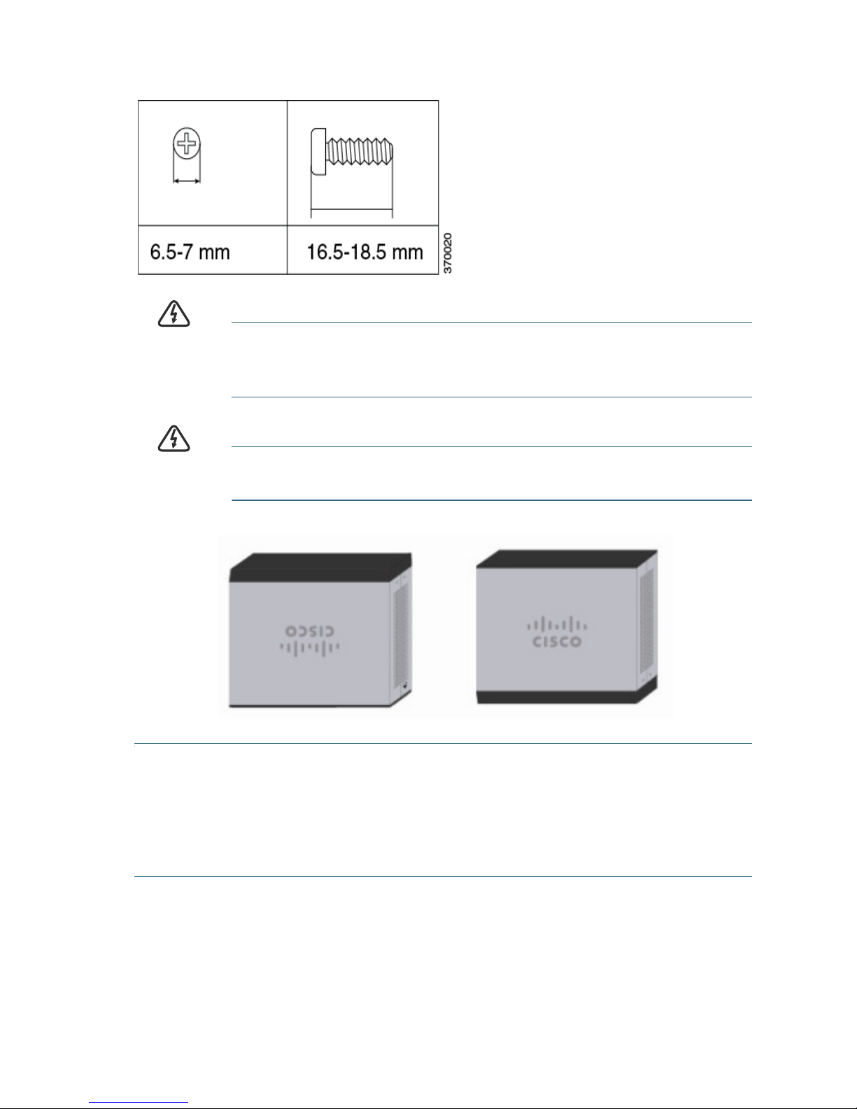
Wall Mounting
The router has two wall-mount slots on the bottom panel. To mount the
router on a wall, you need mounting hardware (not included). Suggested
hardware is illustrated below (not true to scale).
RV320
1
Page 3
Cisco RV320/RV325 Gigabit Dual WAN VPN Router Quick Start Guide 3
RV325
WARNING Insecure mounting might damage the router or cause injury.
Cisco is not responsible for damages incurred by insecure wallmounting.
WARNING
For safety, ensure that the heat dissipation holes are facing
sideways
.
STEP 1 Drill two pilot holes, approximately 109 mm apart, into the surface.
STEP 2 Insert a screw into each hole, leaving a gap between the surface
and the base of the screw head of 1 to 1.2 mm.
STEP 3 Place the router wall-mount slots over the screws and slide the
router down until the screws fit snugly into the wall-mount slots.
Page 4

4 Cisco RV320/RV325 Gigabit Dual WAN VPN Router Quick Start Guide
Cisco RV320 Features
Front Panel
PWR—Lit to indicate the unit is powered on and booted. Blinks when the
device is booting.
VPN—Lit green when the designated VPN tunnel is up. Blinks green when
data is being sent or received through the tunnel. Lit amber when the
tunnel is disconnected. Blinks amber when attempting to establish the
tunnel.
DMZ—Lit green when the DMZ/WAN port is configured as a DMZ.
DIAG—Blinks red when the firmware is updating. Lit red when the device
is booting.
LINK/ACT—Lit steady when a link between a port and another device is
detected. Flashes when a port is passing traffic.
GIGABIT—Lit when another device is connected to a port and a
1000 Mbps link is established. Off when the connection speed is under
1000 Mbps or no other device is attached to a port.
LAN 1-4—Lit when the LAN ports on the back panel are linked to another
device. Blinks when passing traffic.
DMZ/WAN—Lit when a device is connected to the DMZ/WAN port.
Flashes when sending or receiving data over the WAN DMZ port.
WAN—Lit when the WAN port is connected. The light is off when it is not
connected to the Internet or it is connected by using a USB dongle. Blinks
when it is sending or receiving data over the WAN connection.
USB 1 and USB 2—Lit green when the corresponding port is connected
to a device. Flashes green when the port is sending or receiving data.
RESET—Reboot or reboot and restore defaults:
• To reboot the unit and retain the current configuration, press and hold
RESET for at least 3, but no more than 10 seconds, by using a paper
clip or a pen tip.
• To reboot the unit and restore the factory default configuration, press
and hold in the RESET button for more than 10 seconds. Changes you
have made to the configuration of your device are lost.
2
Page 5

Cisco RV320/RV325 Gigabit Dual WAN VPN Router Quick Start Guide 5
Back Panel
POWER—Toggles power to the device on or off.
12VDC (1.5A)—Power port that connects the device to the provided
12VDC, 1.5 amp power adapter.
LAN (1-4)—RJ-45 connectors that link local area network devices, such as
PCs, print servers, or switches, to the device.
DMZ/WAN—Internet device connection supporting a DMZ for connecting
the device to a wide area network device, such as a cable or DSL modem.
WAN—Internet connection for connecting the device to a wide area
network device, such as a cable or DSL modem.
USB 1—Type A USB port that supports flash drives and 3G/4G/LTE USB
dongles. Caution: Use only the power supply provided with the device;
using another power supply might cause the USB dongle to fail.
Side Panel
USB 2—Type A USB port that supports flash drives and 3G/4G/LTE USB
dongles. Caution: Use only the power supply provided with the device;
using another power supply might cause the USB dongle to fail.
Cisco RV325 Features
Front Panel
PWR—Lit to indicate the unit is powered on and booted. Blinks when the
device is booting.
VPN—Lit green when the designated VPN tunnel is up. Blinks green when
data is being sent or received through the tunnel. Lit amber when the
tunnel is disconnected. Blinks amber when attempting to establish the
tunnel.
DMZ—Lit green when the DMZ/WAN port is configured as a DMZ.
DIAG—Blinks red when the firmware is updating. Lit red when the device
is booting.
USB 1 and USB 2—Lit green when the corresponding port is connected
to a device. Flashes green when the port is sending or receiving data.
LAN 1-14—RJ-45 connectors that link local area network devices, such as
PCs, print servers, or switches, to the device.
WAN—Lit when the WAN port is connected. The light is off when it is not
connected to the Internet or it is connected by using a USB dongle. Blinks
when it is sending or receiving data over the WAN connection.
3
Page 6

6 Cisco RV320/RV325 Gigabit Dual WAN VPN Router Quick Start Guide
DMZ/WAN—Lit when a device is connected to the DMZ/WAN port.
Flashes when sending or receiving data over the WAN DMZ port.
LINK/ACT—Lit steady when a link between a port and another device is
detected. Flashes when a port is passing traffic.
GIGABIT—Lit when another device is connected a port and a 1000 Mbps
link is established. Off when the connection speed is under 1000 Mbps or
no other device is attached to a port.
USB 1—Type A USB port that supports flash drives and 3G/4G/LTE USB
dongles. Caution: Use only the power supply provided with the device;
using another power supply might cause the USB dongle to fail.
RESET—Reboot or reboot and restore defaults:
• To reboot the unit and retain the current configuration, press and hold
RESET for at least 3, but no more than 10 seconds, by using a paper
clip or a pen tip.
• To reboot the unit and restore the factory default configuration, press
and hold in the RESET button for more than 10 seconds. Changes you
have made to the configuration of your device are lost.
Back Panel
POWER—Toggles power to the device on or off.
12VDC (2A)—Power port that connects the device to the provided
12VDC, 2 amp power adapter.
Side Panel
USB 2—Type A USB port that supports flash drives and 3G/4G/LTE USB
dongles. Caution: Use only the power supply provided with the device;
using another power supply might cause the USB dongle to fail.
Page 7

Cisco RV320/RV325 Gigabit Dual WAN VPN Router Quick Start Guide 7
Connecting
You must connect a configuration terminal (PC) to the device by using a
LAN port. The terminal must be in the same wired subnetwork as the
device to perform the initial configuration. As part of the initial
configuration, the device can be configured to allow remote management.
To connect a computer to the device:
STEP 1 Power off all equipment, including the cable or DSL modem, the
computer, and this device.
STEP 2 Use an Ethernet cable to connect your cable or DSL modem to the
WAN por t on t his devic e.
STEP 3 Connect another Ethernet cable from one of the LAN (Ethernet)
ports to the Ethernet port on the computer.
STEP 4 Power on the WAN device and wait until the connection is active.
STEP 5 Connect the power adapter to the 12VDC port of this device.
CAUTION Use only the power adapter that is supplied with the device.
Using a different power adapter could damage the device or
cause the USB dongles to fail.
The POWER switch is on by default. The power light on the front
panel is lit when the power adapter is connected properly and the
device is finished booting.
STEP 6 Plug the other end of the adapter into an electrical outlet. Use the
plug (supplied) specific to your country.
STEP 7 Power on the computer that you connected to the LAN port in
Step 3. Your computer becomes a DHCP client of the device and
receives an IP address in the 192.168.1.xxx range.
4
Page 8

8 Cisco RV320/RV325 Gigabit Dual WAN VPN Router Quick Start Guide
Logging In
To l o g in to t h e d ev ic e :
STEP 1 Launch a web browser.
STEP 2 In the address bar, enter the default IP address of the device,
https://192.168.1.1. A site security certificate message is
displayed. The Cisco RV320/RV325 uses a self-signed security
certificate. This message appears because the device is not
known to your computer.
STEP 3 Click Continue to this website (or the option shown on your
particular web browser) to continue. The login displays.
STEP 4 Enter the username and password. The default username is cisco.
The default password is cisco. Passwords are case sensitive.
STEP 5 Click Log In. The Device Manager application starts.
We recommend that you change the password. You are required to
change the password before enabling features such as remote
management.
Changing the Administrator Username and Password
To change the Administrator username and password on the device:
STEP 1 From the Getting Started page, select Change Administrator
Password or select Setup > Password from the navigation bar.
STEP 2 Change the Username.
STEP 3 Enter the Old Password.
STEP 4 Enter the New Password.
STEP 5 Confirm the New Password.
STEP 6 Click Save.
Troubleshoot Your Connection
If you cannot access your device by using Device Manager, the device
might not be reachable from your computer. You can test network
connections by using ping on a computer running Windows:
STEP 1 Open a command window by using Start > Run and enter cmd.
STEP 2 At the Command window prompt, enter ping and the device IP
address. For example, ping 192.168.1.1 (the default static IP
address of the device).
Page 9

Cisco RV320/RV325 Gigabit Dual WAN VPN Router Quick Start Guide 9
If you can reach the device, you should get a reply similar to the
following:
Pinging 192.168.1.1 with 32 bytes of data:
Reply from 192.168.1.1: bytes=32 time<1ms TTL=128
If you cannot reach the device, you should get a reply similar to the
following:
Pinging 192.168.1.1 with 32 bytes of data:
Request timed out.
Possible Causes and Resolutions
Bad Ethernet connection:
Check the LEDs for the proper indications. Check the connectors of the
Ethernet cable to ensure they are firmly plugged into the device and
your computer.
Wrong or conflicting IP address:
Verify that you are using the correct IP address of the device.
Verify that no other device is using the same IP address as this device.
No IP route:
If the device and your computer are in different IP subnetworks,
remote access must be enabled and you need at least one router on
the network to route the packets between the two subnetworks.
Unusually long access time:
Adding new connections might take 30 to 60 seconds for the affected
interfaces and/or LAN to become operational.
Where to Go From Here
Support
Cisco Small Business
Support Community
www.cisco.com/go/smallbizsupport
Cisco Small Business
Support and Resources
www.cisco.com/go/smallbizhelp
5
Page 10

Americas Headquarters
Cisco Systems, Inc.
170 West Tasman Drive
San Jose, CA 95134-1706 USA
www.cisco.com
Small Business Support, Global:
www.cisco.com/go/sbsc
Cisco and the Cisco logo are trademarks or registered trademarks of Cisco and/or its affiliates
in the U.S. and other countries. To view a list of Ciscotrademarks, go to this URL:
www.cisco.com/go/trademarks. Third-party trademarks mentioned are the property of their
respective owners. The use of the word partner does not imply a partnership relationship
between Cisco and any other company. (1110R)
© 2013 Cisco Systems, Inc. All rights reserved.
78-20927-03
Phone Support Contacts www.cisco.com/en/US/support/
tsd_cisco_small_business
_support_center_contacts.html
Cisco Small Business
Firmware Downloads
www.cisco.com/cisco/software/
navigator.html?i=!ch
Select a link to download firmware for Cisco
Small Business Products. No login is
required.
Product Documentation
Cisco Small Business
Routers and Firewalls
www.cisco.com/go/smallbizrouters
Cisco Small Business
Cisco Partner Central
for Small Business
(Partner Login Required)
www.cisco.com/web/partners/sell/smb
Cisco Small Business
Home
www.cisco.com/smb
 Loading...