

Cisco WRP400-G1 - Wireless Router, WRP400, Small Business Pro WRP400 Administration Manual
Cisco Small Business Pro
WRP400
Wireless-G Broadband Router with 2 Phone Ports and
Built-In Analog Telephone Adapter
ADMINISTRATION
GUIDE

CCDE, CCSI, CCENT, Cisco Eos, Cisco HealthPresence, the Cisco logo, Cisco Lumin, Cisco Nexus, Cisco Nurse Connect, Cisco Stackpower,
Cisco StadiumVision, Cisco TelePresence, Cisco WebEx, DCE, and Welcome to the Human Network are trademarks; Changing the Way We Work, Live, Play, and
Learn and Cisco Store are service marks; and Access Registrar, Aironet, AsyncOS, Bringing the Meeting To You, Catalyst, CCDA, CCDP, CCIE, CCIP, CCNA,
CCNP, CCSP, CCVP, Cisco, the Cisco Certified Internetwork Expert logo, Cisco IOS, Cisco Press, Cisco Systems, Cisco Systems Capital, the Cisco Systems
logo, Cisco Unity, Collaboration Without Limitation, EtherFast, EtherSwitch, Event Center, Fast Step, Follow Me Browsing, FormShare, GigaDrive, HomeLink,
Internet Quotient, IOS, iPhone, iQuick Study, IronPort, the IronPort logo, LightStream, Linksys, MediaTone, MeetingPlace, MeetingPlace Chime Sound, MGX,
Networkers, Networking Academy, Network Registrar, PCNow, PIX, PowerPanels, ProConnect, ScriptShare, SenderBase, SMARTnet, Spectrum Expert,
StackWise, The Fastest Way to Increase Your Internet Quotient, TransPath, WebEx, and the WebEx logo are registered trademarks of Cisco Systems, Inc. and/
or its affiliates in the United States and certain other countries.
All other trademarks mentioned in this document or website are the property of their respective owners. The use of the word partner does not imply a
partnership relationship between Cisco and any other company. (0903R)
© 2009 Cisco Systems, Inc. All rights reserved. OL-19688-01

Contents
Chapter 1: Product Overview and Deployment Guidelines 5
WRP400 Features and Benefits 5
Deployment Models 6
Deploying the WRP400 in a Basic Network 7
Deploying the WRP400 with a Wireless Guest Network 8
Deploying the WRP400 with Mobile Broadband 9
Local Area Network Guidelines 11
Power, Cabling and Telephone Lines 11
Basic Services and Equipment 11
Special Requirements for Voice Deployments 12
Bandwidth for Voice Deployments 12
NAT Mapping for Voice over IP Deployments 14
Local Area Network Design for Voice Deployments 14
WRP400 Maintenance Operations 15
Remote Provisioning 17
Upgrade URL 17
Resync URL 18
Reboot URL 19
Configuration Profile 19
Chapter 2: Configuring Your System for ITSP Interoperability 21
Configuring NAT Mapping 21
Configuring NAT Mapping with a Static IP Address 21
Configuring NAT Mapping with STUN 23
Determining Whether the Router Uses Symmetric or Asymmetric NAT 25
Firewalls and SIP 26
Configuring SIP Timer Values 27
Chapter 3: Configuring Voice Services 28
Understanding Analog Telephone Adapter Operations 28
ATA Software Features 29
Cisco Small Business WRP400 ATA Administration Guide i

Supported Codecs 29
SIP Proxy Redundancy 30
Other ATA Software Features 31
Contents
Registering to the Service Provider 35
Managing Caller ID Service 37
Optimizing Fax Completion Rates 39
Fax Troubleshooting 40
Silence Suppression and Comfort Noise Generation 41
Configuring Dial Plans 42
About Dial Plans 42
Editing Dial Plans 50
Secure Call Implementation 52
Enabling Secure Calls 52
Secure Call Details 53
Using a Mini-Certificate 54
Generating a Mini Certificate 55
Appendix A: Advanced Voice Fields 57
Info page 57
System page 61
SIP page 62
Regional page 72
Line page 92
User page 111
Appendix B: Data Fields 117
Setup 117
Setup > Basic Setup 118
Setup > DDNS 125
Setup > MAC Address Clone 126
Setup > Advanced Routing 126
Cisco Small Business WRP400 ATA Administration Guide ii

Setup > Mobile Network 127
Setup > Connection Recovery 129
Contents
Wireless Configuration 130
Wireless > Basic Wireless Settings 131
Wireless > Wireless Security 132
Wireless > Wireless MAC Filter 133
Wireless > Advanced Wireless Settings 134
Security 135
Security > Firewall 136
Security > VPN Passthrough 137
Access Restrictions 138
Access Restrictions > Internet Access 138
Applications and Gaming 139
Applications and Gaming > Single Port Forwarding 139
Applications and Gaming > Port Range Forwarding 139
Applications & Gaming > Port Range Triggering 141
Applications & Gaming > DMZ 141
Applications and Gaming > QoS (Quality of Service) 141
Administration 143
Administration > Management 143
Administration > Log 146
Administration > Diagnostics 147
Administration > Factory Defaults 147
Status 148
Status > Router 148
Status > Mobile Network 149
Status > Local Network 150
Status > Wireless Network 150
Appendix C: WRP400 Provisioning Reference 151
Appendix D: Troubleshooting 165
Cisco Small Business WRP400 ATA Administration Guide iii

Contents
Appendix E: Environmental Specifications for the WRP400 169
Appendix F: Where to Go From Here 170
Cisco Small Business WRP400 ATA Administration Guide iv

1
Product Overview and Deployment Guidelines
This chapter describes the features and benefits of the WRP400, describes
deployment scenarios, and offers guidelines to help you plan your network.
• “WRP400 Features and Benefits,” on page 5
• “Deployment Models,” on page 6
• “Local Area Network Guidelines,” on page 11
• “Special Requirements for Voice Deployments,” on page 12
• “WRP400 Maintenance Operations,” on page 15
• “Remote Provisioning,” on page 17
WRP400 Features and Benefits
With a variety of features, the WRP400 offers the benefits of five devices in one:
1. Router: The WRP400 is a broadband router with a robust security firewall to
protect your network.
2. Switch: The WRP400 includes a built-in, 4-port, full-duplex, 10/100 Ethernet
switch to connect computers, printers, and other equipment directly or to attach
additional hubs and switches. Advanced Quality of Service functionality
ensures that you can prioritize traffic for data, voice, and video applications.
3. Analog Telephone Adapter: The WRP400 includes a two-port Analog
Telephone Adapter (ATA) that allows you to connect your analog phones or fax
machines to your configured Internet telephone service. Two traditional phone
lines also can be connected for support of legacy phone numbers and fax
numbers.
Cisco Small Business WRP400 Administration Guide 5

Product Overview and Deployment Guidelines
Deployment Models
4. Wireless Access Point: The WRP400 has an integrated 802.11b/g wireless
access point that secures your communications with WEP and WPA security
protocols. It is preconfigured to support two wireless networks: one for private
use by your business and one for guest use by customers, temporary
employees, and other visitors.
5. Mobile Broadband Router: When you attach a compatible Mobile Broadband
Modem to the USB port, the WRP400 allows multiple Wi-Fi devices to share a
mobile broadband connection. This feature also can be used to provide
continuous Internet service by providing automatic failover to the mobile
network when the primary Internet connection is unavailable. For the latest copy
of the USB Modem Compatibility List, visit the following URL:
www.cisco.com/en/US/products/ps10028/index.html
NOTE Because this device has many unique functions, the administrative tasks for the
WRP400 may be different from corresponding tasks on other Cisco Small Business
routers, switches, and ATAs. Administrators should refer to this guide for the proper
procedures for installation, configuration, and management of the WRP400.
1
Deployment Models
The versatility of the WRP400 makes it useful for a variety of deployments. Three
are described in this section.
• Deploying the WRP400 in a Basic Network, page 7
• Deploying the WRP400 with a Wireless Guest Network, page 8
• Deploying the WRP400 with Mobile Broadband, page 9
Cisco Small Business WRP400 Administration Guide 6

Product Overview and Deployment Guidelines
Private Network
194231
Deployment Models
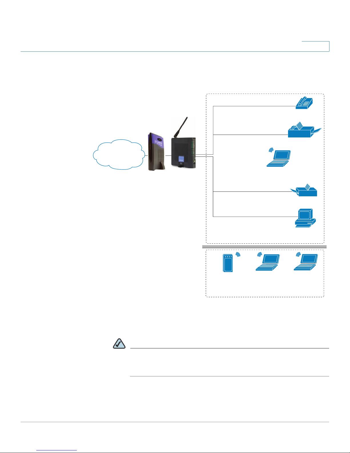
Deploying the WRP400 in a Basic Network
Internet
1
Analog phone
Fax
WRP400
Laptop
computer
Printer
Personal
computer
In this scenario, the WRP400 is deployed in a small business that has a basic
network configuration.
• The WRP400 is preconfigured by the Service Provider to act as the edge
device that routes traffic between the small business network and the
Service Provider network.
NOTE The WRP400 may be configured as an edge device or can be
connected to another device that provides access to the Service
Provider network.
• The WRP400 connects the computers to the Internet. Computers may be
connected by network cables or may operate wirelessly. All computers
have access to the printer on the local network.
• An analog phone and a fax machine are connected to the WRP400 phone
ports and have access to the configured Voice over IP services.
Cisco Small Business WRP400 Administration Guide 7
Product Overview and Deployment Guidelines
Internet Access
Device
Wireless Guest Network
Personal
computer
WRP400
Laptop
computer
Analog phone
Fax
Printer
Private Network
Internet
194232
Deployment Models
Deploying the WRP400 with a Wireless Guest Network
1
In this example, the WRP400 is deployed in an Internet cafe.
• The WRP400 is connected to a cable modem that provides Internet access.
NOTE The WRP400 may be configured as an edge device or can be
connected to another device that provides access to the Service
Provider network.
• In the private network, a computer is connected to the WRP400 by an
Ethernet cable. The manager also has a laptop computer that can be used
wirelessly from anywhere on the premises, using the main wireless
Cisco Small Business WRP400 Administration Guide 8

Product Overview and Deployment Guidelines
Mobile Office Network
194234
*with compatible 3G USB Modem
WRP400*
Wi-Fi Phone
Deployment Models
network, SSID1. The manager and employees using SSID1 have access to
the printer. If desired, a wireless phone also could be connected to this
network for business use.
• An analog phone and a fax machine are in the private network. The WRP400
is configured for Internet telephone service and for traditional telephone
service through a connected phone line.
• The WRP400 is configured with a guest network, SSID2, that enables the
business to provide its customers with a free wireless hotspot for their
laptop computers and other mobile devices. Because this network is
separate from the main wireless network, the customers have no access to
the manager’s computer, the printer, or the telephone service.
Deploying the WRP400 with Mobile Broadband
1
When a compatible mobile broadband modem is connected to the USB port, the
WRP400 can connect to a mobile broadband network. The mobile network can be
the primary network or can serve as a backup network to ensure continuous
Internet connectivity. Consider the two scenarios illustrated below.
Mobile Office Using the Mobile Network for Internet Access
Laptop
computer
Mobile
network
1
WRP400
Printer
Wireless Phone
In this example, a team has set up a temporary network at a construction site. The
team members have laptop computers and Wi-Fi phones that share a mobile
broadband connection for Internet access. All computers can connect to the
printer on the local network. If a Virtual Private Network (VPN) tunnel is configured
on the laptop computer, team members also can securely connect to resources at
the main office (not illustrated).
Cisco Small Business WRP400 Administration Guide 9

Product Overview and Deployment Guidelines
Personal
computer
WRP400
Laptop
computer
Analog phone
Fax
Printer
Private Network
Internet
194233
1
Mobile
network
Failov
e
r
*with compatible 3G USB Modem
WRP400*
Deployment Models
Basic Office Deployment Using the Mobile Network as a Backup
Connection
1
In this example, the business has the same network as illustrated in Deploying the
WRP400 in a Basic Network, page 7. However, this business has the added
benefit of using the mobile broadband network as a backup network to ensure
continuous Internet connectivity. In the event that the Internet connection fails, the
WRP400 fails over to the configured mobile network. When the Internet
connection becomes available, the WRP400 recovers the connection.
Cisco Small Business WRP400 Administration Guide 10

Product Overview and Deployment Guidelines
Local Area Network Guidelines
Local Area Network Guidelines
This section offers guidelines for setting up your Local Area Network (LAN).
NOTE As you design your network, be aware that the WRP400 is intended for deployment
in a very small business. The router is designed to handle the data, voice, and video
traffic that would be expected by office personnel who use the Internet to find data,
conduct phone conversations, transmit email, and participate in videoconferences.
For large-scale operations with heavy data, voice, and video requirements,
consider other models of Cisco Small Business routers.
Power, Cabling and Telephone Lines
1
• AC outlets: Ensure there is an AC outlet available for every network device that
requires AC power.
- The WRP400 requires power, and Ethernet switches (optional) require
power.
- Some analog telephones require AC power.
• Ethernet cabling: If an Internet access device is present, you will need to
connect it to the WRP400 with an Ethernet cable. You also will need Ethernet
cable for any devices that do not have wireless connectivity. It is
recommended that Ethernet cables are UTP Cat5e or better.
• PSTN lines: Ensure that the lines are operative and that any features, such as
caller identification, operate properly before starting the installation.
• UPS: It is strongly recommended that you included an Uninterrupted Power
Supply (UPS) mechanism in your network to ensure continuous operation
during a power failure. Connect all essential devices, including the Internet
access device, WRP400, and the Ethernet switch (if present).
Basic Services and Equipment
The following basic services and equipment are required:
• An Integrated access device or modem for broadband access to the Internet
• Business grade Internet service
Cisco Small Business WRP400 Administration Guide 11

Product Overview and Deployment Guidelines
Special Requirements for Voice Deployments
• Internet Telephony Service Provider (ITSP) for Voice Over IP telephone service,
supporting a “bring your own device” model
• A computer with Microsoft Windows XP or Windows Vista for system
configuration
Special Requirements for Voice Deployments
Voice deployments have special requirements that you must meet to ensure voice
quality.
• “Bandwidth for Voice Deployments,” on page 12
• “NAT Mapping for Voice over IP Deployments,” on page 14
1
• “Local Area Network Design for Voice Deployments,” on page 14
Bandwidth for Voice Deployments
You can choose from several types of broadband access technologies to provide
symmetric or asymmetric connectivity to a small business. These technologies
vary on the available bandwidth and on the quality of service. For voice
deployments, it is generally recommended that you use broadband access with a
Service Level Agreement that provides quality of service. If there is not a Service
Level Agreement with regard to the broadband connection quality of service, the
downstream audio quality may be affected negatively under heavy load
conditions (bandwidth utilization beyond 80%).
To eliminate or minimize this effect, Cisco recommends one of the following
actions:
• For broadband connections with a bandwidth lower than 2 Mbps, perform the
call capacity calculations by assuming a bandwidth value of 50% of the
existing broadband bandwidth. For example, in the case of a 2 Mbps uplink
broadband connection, assume 1 Mbps. Limit the uplink bandwidth in the
Integrated Access Device to this value. This setting helps to maintain the
utilization levels below 60%, thus reducing jitter and packet loss.
• Use an additional broadband connection for voice services only. A separate
connection is required when the broadband connection services do not offer
quality of service and when it is not possible to apply the above mentioned
utilization mechanism.
Cisco Small Business WRP400 Administration Guide 12

Product Overview and Deployment Guidelines
Special Requirements for Voice Deployments
The available connection bandwidth determines the maximum number of
simultaneous calls that the system can support with the appropriate audio quality.
Use this information to determine the maximum number of simultaneous VoIP
connections that the system can support.
For asymmetric connections, such as ADSL, the maximum number of calls is
determined by the upstream bandwidth. In general it is a good practice to use no
more than 75% of the total available bandwidth for calls. This provides space for
data traffic and helps ensure good voice quality.
NOTE Some ITSP SIP trunk services limit the maximum number of simultaneous calls.
Please check with your Service Provider to understand the maximum number of
simultaneous calls each SIP trunk supports.
The following table provides the approximate bandwidth budget for different
codecs.
1
Codec Approximate bandwidth
budget for each side of
conversation
G.711 110 kbps 220
G.726-4087 kbps 174
G.726-3279 kbps 158
G.726-2471 kbps 142
G.726-1663 kbps 126
G.729 55 kbps 110
For more information about bandwidth calculation, refer to the following web sites:
www.erlang.com/calculator/lipb/
www.bandcalc.com/
2 calls 4 calls 6 calls 8 calls
kbps
kbps
kbps
kbps
kbps
kbps
440
kbps
348
kbps
316
kbps
284
kbps
252
kbps
220
kbps
660
kbps
522
kbps
474
kbps
426
kbps
378
kbps
330
kbps
880
kbps
696
kbps
632
kbps
568
kbps
504
kbps
440
kbps
Cisco Small Business WRP400 Administration Guide 13

Product Overview and Deployment Guidelines
Special Requirements for Voice Deployments
NAT Mapping for Voice over IP Deployments
Network Address Translation (NAT) is the function that allows multiple devices in
your small business network to share one external (public) IP address that you
receive from your Internet Service Provider. Voice over IP can co-exist with NAT
only when some form of NAT traversal is provided.
Some Internet Telephone Service Providers (ITSPs) provide NAT traversal, but
some do not. For voice deployments, it is strongly recommended that you
choose an ITSP that supports NAT mapping through a Session Border
Controller.
If your ITSP does not provide NAT mapping through a Session Border Controller
(the preferred method), you have three options for providing NAT traversal on your
WRP400:
• Deploy an edge device that has a SIP ALG (Application Layer Gateway). The
Cisco Small Business WRV200 is suited for this purpose, but other SIP-ALG
routers can be used. If your Internet Service Provider is providing the edge
device, check with your provider to determine if the router has a SIP ALG.
1
• Configure NAT mapping with the EXT IP setting. This option requires that you
have (1) a static external (public) IP address from your Internet Service Provider
and (2) an edge device with a symmetric NAT mechanism. If the WRP400 is the
edge device, the second requirement is met. For more information about the
EXT IP setting, see NAT Support Parameters section, page 70.
• Configure Simple Traversal of UDP through NAT (STUN). This option requires
that you have (1) a dynamic external (public) IP address from your service
provider, (2) a computer running STUN server software, and (3) an edge device
with an asymmetric NAT mechanism. If the WRP400 is the edge device, the
third requirement is not met. For more information about the STUN Enable
setting and the STUN Test Enable setting, see NAT Support Parameters
section, page 70.
Local Area Network Design for Voice Deployments
Use the following guidelines to manage the LAN setup for voice deployments.
• Ensure that all telephones are located in the same local area network
subnet.
• Configure your WRP400 as a DHCP server for the purpose of easily adding
network devices to the system. Ensure that the DHCP server can assign
Cisco Small Business WRP400 Administration Guide 14

Product Overview and Deployment Guidelines
WRP400 Maintenance Operations
enough IP addresses to serve the devices that you need to connect to your
network.
• Use stable DNS server addresses for URL name resolution. Your Internet
Service Provider can provide the primary and secondary DNS server IP
addresses.
• If you need to directly connect more than four network devices (other than
wireless devices), you will need to connect an Ethernet switch to the
WRP400. For voice deployments, Cisco recommends use of the SLMxxxP,
SRWxxxP and SRWxxxMP switch product families. The SLM224P is a
popular choice. For more information about these switches, visit the
following URL: www.cisco.com/cisco/web/solutions/small_business/
products/routers_switches/index.html
• If you use an Ethernet switch, configure it to ensure voice quality. The
following settings are recommended:
1
- Enable Port Fast and Spanning Tree Protocol on the ports to which your
voice devices are connected. The Cisco phones are capable of
rebooting in a few seconds and will attempt to locate network services
while a switch port is being blocked by STP after it senses a device
reboot. Enabling Port Fast means that the network will be available to the
phones when needed. If the switch does not provide a way to enable
Port Fast, then you must disable Spanning Tree Protocol.
- In the administrative web pages for the switch, you should enable QoS
and choose DSCP as the Trust Mode.
WRP400 Maintenance Operations
Due to its unique functions, the WRP400 has unique maintenance operations as
compared to other Cisco Small Business IP telephony devices.
NOTE For complete instructions about the settings mentioned below, see the WRP400
User Guide.
• Remote Management: For security purposes, remote management is
disabled by default.
- When you first configure the WRP400, connect your administrative
Cisco Small Business WRP400 Administration Guide 15
computer directly to one of the LAN ports and enter the default static IP

Product Overview and Deployment Guidelines
WRP400 Maintenance Operations
address into your web browser to log on to the configuration utility.
NOTE The default LAN IP address of the WRP400 is 192.168.15.1. If another
device on the network has the same IP address, the WRP400 will take
the address 192.168.16.1. You can modify the Local IP Address on the
Setup tab > Basic Setup page, Network Setup section.
If you are using the IVR, be aware that this address is NOT the address
reported by the 110 option of the IVR. The device does not respond
to the 110 option address.
- If you wish to enable web access and wireless access to the
configuration utility, you can use the Administration tab > Management
page, Web Access section.
1
• DHCP Server: The DCHP server is disabled by default. If there are no other
DHCP servers on your network, you can enable the DHCP server option to
allow your WRP400 to assign IP addresses to connected devices
automatically. This setting is on the Setup tab > Basic Setup page, DHCP
Server Setting section.
• System Logging: If you wish to enable system logging, be aware that there
are two sets of system logs: one for the data (router) functions and another
for the voice functions.
- Data (router) logging: See the Administration tab > Logging page.
- Voice logging: See the Voice tab > System page, Miscellaneous
Settings section.
• Factory Reset: If you wish to reset your WRP400 to the factory default
settings, you can reset the data (router) settings and the voice settings
separately.
Factory reset of data (router) settings: Use one of the following methods:
- Option 1: Log on to the configuration utility, and then click
Administration > Factory Defaults. Next to Restore Router Factory
Defaults, click Yes . Then click Save Settings to begin the operation.
- Option 2: Press and hold the reset button located on the side panel for
Cisco Small Business WRP400 Administration Guide 16
approximately ten seconds.

Product Overview and Deployment Guidelines
Remote Provisioning
Factory reset of voice settings: Use one of the following methods:
- Option 1: Log on to the configuration utility, and then click
Administration tab > Factory Defaults. Next to Restore Voice Factory
Defaults, click Yes . Then click Save Settings to begin the operation.
- Option 2: Connect an analog phone to the Phone 1 or Phone 2 port.
Press **** to access the Interactive Voice Response menu. After you
hear the greeting, press 73738 for factory reset. Listen to the prompts
and then press 1 to confirm or * to cancel. After you hear “Option
successful,” you can hang up the phone.
Remote Provisioning
Like other Cisco Small Business IP Telephony Devices, the WRP400 provides for
secure provisioning and remote upgrade. Provisioning is achieved through
configuration profiles transferred to the device via TFTP, HTTP, or HTTPS. To
configure Provisioning, go to the Provisioning tab in the Configuration Utility.
1
NOTE For complete details, see the Provisioning Guide at the following URL:
www.cisco.com/en/US/docs/voice_ip_comm/csbpvga/ata/provisioning/guide/
Cisco_Small_Business_IP_Telephony_Provisioning_Guide.pdf
Upgrade URL
Remote firmware upgrade is achieved via TFTP or HTTP (firmware upgrades
using HTTPS are not supported). Remote upgrades are initiated by causing the
WRP400 to request the upgrade firmware image by providing a URL for the
WRP400 to retrieve the firmware.
NOTE If the value of the
cannot upgrade the WRP400 even if the web page indicates otherwise.
The syntax of the Upgrade URL is as follows:
http://WRP400_ip_address/admin/upgrade?[protocol://][server-
name[:port]][/firmware-pathname]
Upgrade Enable
parameter in the Provisioning page is No, you
Cisco Small Business WRP400 Administration Guide 17

Product Overview and Deployment Guidelines
Remote Provisioning
Both HTTP and TFTP are supported for the upgrade operation.
1
protocol
If no
host that requests the URL is used as
If no port specified, the default port of the protocol is used. (69 for TFTP or 80 for
HTTP)
The
firmware-pathname
directory on the TFTP or HTTP server. If no
spa.bin
http://192.168.2.217/admin/upgrade?tftp://192.168.2.251/
spa.bin
is specified, TFTP is assumed. If no
server-name
is typically the file name of the binary located in a
firmware-pathname
is assumed, as in the following example:
server-name
.
is specified, the
is specified,
/
Resync URL
The WRP400 can be configured to automatically resync its internal configuration
state to a remote profile periodically and on power up. The automatic resyncs are
controlled by configuring the desired profile URL into the device.
The Resync URL lets you force the WRP400 to do a resync to a profile specified in
the URL, which can identify either a TFTP, HTTP, or HTTPS server. The syntax of
the Resync URL is as follows:
http://WRP400_ip_address/admin/resync?[[protocol://][server-
name[:port]]/profile-pathname]
NOTE The WRP400 resyncs only when it is idle.
If no parameter follows
page is used.
protocol
If no
host that requests the URL is used as
If no port is specified, the default port is used (69 for TFTP, 80 for HTTP, and 443
for HTTPS).
The profile-path is the path to the new profile with which to resync, for example:
http://192.168.2.217/admin/resync?tftp://192.168.2.251/
spaconf.cfg
is specified, TFTP is assumed. If no
/resync?,
the Profile Rule setting from the Provisioning
server-name
server-name
.
is specified, the
Cisco Small Business WRP400 Administration Guide 18

Product Overview and Deployment Guidelines
Remote Provisioning
Reboot URL
The Reboot URL lets you reboot the WRP400. The Reboot URL is as follows:
http://WRP400_ip_address/admin/reboot
NOTE The WRP400 reboots only when it is idle.
Configuration Profile
Because the WRP400 has two sets of parameters, one set for data and one set for
voice, the requirements vary from the provisioning of other Cisco Small Business
IP Telephony Devices. You will have two profiles: one for the data (router)
parameters and one for the voice parameters. One benefit of having separate
profiles for voice parameters and data parameters is that you can deploy the
common data parameters to all of your customer sites and deploy the custom
voice parameters to each site individually.
1
• Data (router) parameters: Use the XML format only, as described in the
Provisioning Guide. Binary files are not supported for the configuration of
data (router) parameters. For more information about the data parameters,
see Appendix B, “Data Fields.”
• Voice parameters: Use the binary or XML format. The binary format is
generated by a profile compiler tool available from Cisco. Find the correct
SPA Profiler Compiler (SPC) for the firmware that you have installed on your
WRP400. For more information about the data parameters, see Appendix A,
“Advanced Voice Fields.”
NOTE You can download the SPC at the following URL: tools.cisco.com/
support/ downloads/go/Redirect.x?mdfid=282414113
Cisco Small Business WRP400 Administration Guide 19

Product Overview and Deployment Guidelines
Remote Provisioning
XML Format
Use the XML format for data (router) parameters. The XML file consists of a series
of elements (one per configuration parameter), encapsulated within the element
tags <flat-profile> … </flat-profile>. The encapsulated elements specify values for
individual parameters. Here is an example of a valid XML profile:
<flat-profile>
<Admin_Passwd>some secret</Admin_Passwd>
<Upgrade_Enable>Yes</Upgrade_Enable>
</flat-profile>
The names of parameters in XML profiles can generally be inferred from the
WRP400 Configuration Utility, by substituting underscores (_) for spaces and other
control characters. To distinguish between Lines 1, 2, 3, and 4, corresponding
parameter names are augmented by the strings _1_, _2_, _3_, and _4_. For
example, Line 1 Proxy is named Proxy_1_ in XML profiles. For more information,
see Appendix C, “WRP400 Provisioning Reference.”
1
Binary Format
Binary format profiles contain voice parameter values and user access
permissions for the parameters. By convention, the profile uses the extension .cfg
(for example, spa2102.cfg). The Profile Compiler (SPC) tool compiles a plain-text
file containing parameter-value pairs into a properly formatted and encrypted .cfg
file.
The syntax of the plain-text file accepted by the profile compiler is a series of
parameter-value pairs, with the value in double quotes. Each parameter-value pair
is followed by a semicolon. Here is an example of a valid text source profile for
input to the SPC tool:
Admin_Passwd “some secret”;
Upgrade_Enable “Yes”;
The names of parameters in the source text files for the SPC tool can generally be
inferred from the WRP400 Configuration Utility, by substituting underscores (_) for
spaces and other control characters. To distinguish between Line 1, 2, 3, and 4,
corresponding parameter names are augmented by adding [1], [2], [3], or [4]. For
example, the Line 1 Proxy is named Proxy[1] in source text profiles for input to the
SPC.
Cisco Small Business WRP400 Administration Guide 20

Configuring Your System for ITSP
Interoperability
This chapter provides configuration details to help you to ensure that your
infrastructure properly supports voice services.
• “Configuring NAT Mapping,” on page 21
• “Firewalls and SIP,” on page 26
2
• “Configuring SIP Timer Values,” on page 27
Configuring NAT Mapping
As discussed in Chapter 1, “Product Overview and Deployment Guidelines,”
some form of NAT mapping is needed to support VoIP. If your ITSP does not
support NAT mapping through a Session Border Controller, and your edge device
is not a SIP-ALG router, you can address this issue through one of the following
methods:
• “Configuring NAT Mapping with a Static IP Address,” on page 21
• “Configuring NAT Mapping with STUN,” on page 23
Configuring NAT Mapping with a Static IP Address
This option can be used if the following requirements are met:
• You must have a static external (public) IP address from your ISP.
• The edge device—that is, the router between your local area network and your
ISP network—must have a symmetric NAT mechanism. If the WRP400 is the
edge device, this requirement is met. If another device is used as the edge
device, see “Determining Whether the Router Uses Symmetric or
Asymmetric NAT,” on page 25.
Cisco Small Business WRP400 Administration Guide 21
Configuring Your System for ITSP Interoperability
Configuring NAT Mapping
• If the WRP400 is connected to an Ethernet switch, the switch must be
configured to enable Spanning Tree Protocol and Port Fast on the port to which
the WRP400 is connected.
NOTE Use NAT mapping only if the ITSP network does not provide a Session Border
Controller functionality.
STEP 1 Start Internet Explorer, connect to the Configuration Utility, and choose Voice >
Admin Login. If prompted, enter the administrative login provided by the Service
Provider. (The default username and password are both admin.)
STEP 2 Under the Voice menu, click SIP.
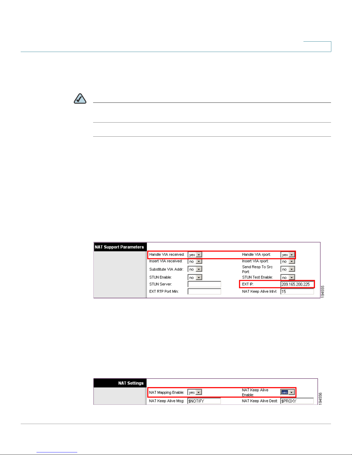
STEP 3 In the NAT Support Parameters section, enter the following settings:
2
• Handle VIA received, Insert VIA received, Substitute VIA Addr: Choose yes.
• Handle VIA rport, Insert VIA rport, Send Resp To Src Port: Choose yes.
• EXT IP: Enter the public IP address that was assigned by your ISP.
Voice tab > SIP: NAT Support Parameters
STEP 4
STEP 5 In the NAT Settings section, enter the following settings:
Under the Voice menu, click Line 1 or Line 2 to choose the line interface that you
want to modify.
• NAT Mapping Enable: Choose yes.
• NAT Keep Alive Enable: Choose yes.
Cisco Small Business WRP400 Administration Guide 22
Voice tab > Line N > NAT Settings

Configuring Your System for ITSP Interoperability
Configuring NAT Mapping
STEP 6 Click Save Settings.
NOTE You also need to configure the firewall settings on your router to allow SIP
traffic. See “Firewalls and SIP,” on page 26.
Configuring NAT Mapping with STUN
This option is considered a practice of last resort and should be used only if the
other methods are unavailable. This option can be used if the following
requirements are met:
• You have a dynamically assigned external (public) IP address from your ISP.
2
• You must have a computer running STUN server software.
• The edge device uses an asymmetric NAT mechanism. If the WRP400 is the
edge device, this requirement is not met. For more information, see
“Determining Whether the Router Uses Symmetric or Asymmetric NAT,” on
page 25.
• If the WRP400 is connected to an Ethernet switch, the switch must be
configured to enable Spanning Tree Protocol and Port Fast on the port to which
the WRP400 is connected.
NOTE Use NAT mapping only if the ITSP network does not provide a Session Border
Controller functionality.
STEP 1 Start Internet Explorer, connect to the Configuration Utility, choose Voice > Admin
Login. If prompted, enter the administrative login provided by the Service
Provider. (The default username and password are both admin.)
STEP 2 Under the Voice menu, click SIP.
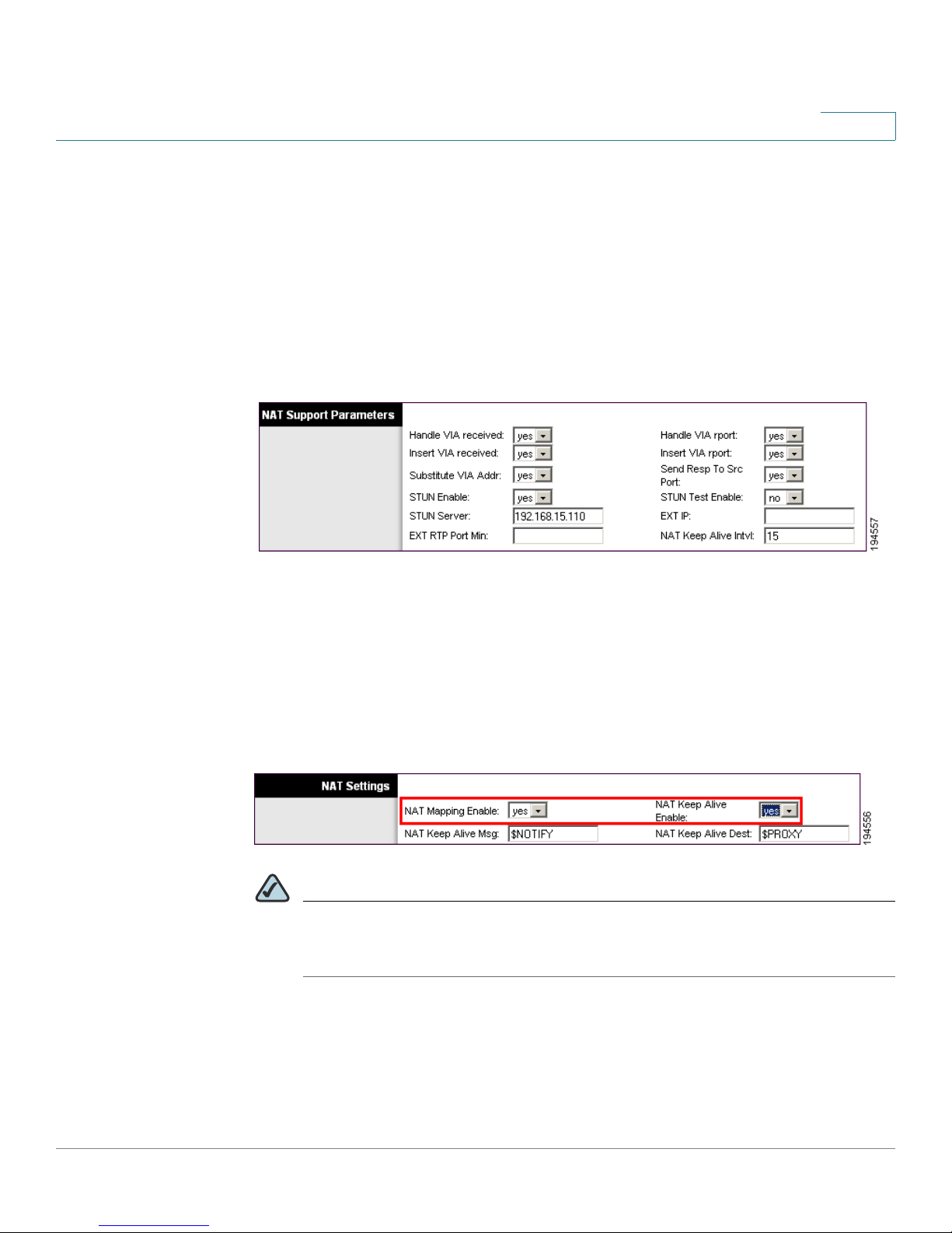
STEP 3 In the NAT Support Parameters section, enter the following settings:
• Handle VIA received: yes
• Handle VIA rport: yes
Cisco Small Business WRP400 Administration Guide 23
Configuring Your System for ITSP Interoperability
Configuring NAT Mapping
• Insert VIA received: yes
• Insert VIA rport: yes
• Substitute VIA Addr: yes
• Send Resp To Src Port: yes
• STUN Enable: Choose yes.
• STUN Server: Enter the IP address for your STUN server.
Voice tab > SIP > NAT Support Parameters
2
STEP 4
STEP 5 In the NAT Settings section, enter the following settings:
Under the Voice menu, click Line 1 or Line 2 to choose the line interface that you
want to modify.
• NAT Mapping Enable: Choose yes.
• NAT Keep Alive Enable: Choose yes (optional).
Voice tab > Line N > NAT Settings
NOTE Your ITSP may require the WRP400 to send NAT keep alive messages to
keep the NAT ports open permanently. Check with your ITSP to determine
the requirements.
Cisco Small Business WRP400 Administration Guide 24

Configuring Your System for ITSP Interoperability
Configuring NAT Mapping
STEP 6 Click Save Settings.
NOTE You also need to configure the firewall settings on your router to allow SIP
traffic. See “Firewalls and SIP,” on page 26.
Determining Whether the Router Uses Symmetric or
Asymmetric NAT
To use a STUN server, the edge device—that is, the device that routes traffic
between your private network and your ISP network—must have an asymmetric
NAT mechanism. You need to determine which type of NAT mechanism is
available on that device.
2
STUN does not work on routers with symmetric NAT. With symmetric NAT, IP
addresses are mapped from one internal IP address and port to one external,
routable destination IP address and port. If another packet is sent from the same
source IP address and port to a different destination, then a different IP address
and port number combination is used. This method is restrictive because an
external host can send a packet to a particular port on the internal host only if the
internal host first sent a packet from that port to the external host.
NOTE This procedure assumes that a syslog server is configured and is ready to receive
syslog messages.
STEP 1 Make sure you do not have firewall running on your computer that could block the
syslog port (port 514 by default).
STEP 2 Start Internet Explorer, connect to the Configuration Utility, choose Voice > Admin
Login. If prompted, enter the administrative login provided by the Service
Provider. (The default username and password are both admin.)
STEP 3 To enable debugging, complete the following tasks:
a. Under the Voice menu, click System.
b. In the Debug Server field, enter the IP address of your syslog server. This
address and port number must be reachable from the WRP400.
Cisco Small Business WRP400 Administration Guide 25

Configuring Your System for ITSP Interoperability
Firewalls and SIP
c. From the Debug level drop-down list, choose 3.
STEP 4 To collect information about the type of NAT your router is using, complete the
following tasks:
a. Under the Voice menu, click SIP.
2
b. Scroll down to the NAT Support Parameters section.
c. From the STUN Test Enable field, choose yes.
STEP 5 To enable SIP signalling, complete the following task:
a. Under the Voice menu, click Line 1 or Line 2 to choose the line interface that
b. In the SIP Settings section, choose full from the SIP Debug Option field.
STEP 6 Click Save Settings.
STEP 7 View the syslog messages to determine whether your network uses symmetric
NAT. Look for a warning header in the REGISTER messages, such as Warning: 399
spa "Full Cone NAT Detected.”
Firewalls and SIP
To enable SIP requests and responses to be exchanged with the SIP proxy at the
ITSP, you must ensure that your firewall allows both SIP and RTP unimpeded
access to the Internet.
you want to modify.
• Make sure that the following ports are not blocked:
• SIP ports—UDP port 5060 through 5063, which are used for the ITSP line
interfaces
Cisco Small Business WRP400 Administration Guide 26

Configuring Your System for ITSP Interoperability
Configuring SIP Timer Values
• RTP ports—16384 to 16482
• Also disable SPI (Stateful Packet Inspection) if this function exists on your
firewall.
Configuring SIP Timer Values
The default timer values should be adequate in most circumstances. However, you
can adjust the SIP timer values as needed to ensure interoperability with your
ISTP. For example, if SIP requests are returned with an “invalid certificate”
message, you may need to enter a longer SIP T1 retry value.
For more information, see ”SIP Timer Values (sec) section,” on page 65 of
Appendix A.
2
Cisco Small Business WRP400 Administration Guide 27

Configuring Voice Services
This chapter describes how to configure your WRP400 to meet the customer’s
requirements for voice services.
• “Understanding Analog Telephone Adapter Operations,” on page 28
• “Managing Caller ID Service,” on page 37
• “Silence Suppression and Comfort Noise Generation,” on page 41
3
• “Configuring Dial Plans,” on page 42
• “Secure Call Implementation,” on page 52
Understanding Analog Telephone Adapter Operations
The WRP400 is equipped with a built-in Analog Telephone Adapter (ATA). An ATA
is an intelligent low-density Voice over IP (VoIP) gateway that enables carrierclass residential and business IP Telephony services delivered over broadband or
high-speed Internet connections. Users can access Internet phone services using
standard analog telephone equipment. In addition, the WRP400 has two line ports
that can be connected to the Public Switched Telephone Network (PSTN) so that
your business can support legacy phone numbers and fax numbers.
Cisco Small Business WRP400 Administration Guide 28
 Loading...