

Page 1
REVIEW DRAFT — CISCO CONFIDENTIAL
ADMINISTRATION
GUIDE
Cisco Small Business Pro
SRP521 Services Ready Platform VoIP Gateway
Page 2

REVIEW DRAFT — CISCO CONFIDENTIAL
CCDE, CCENT, CCSI, Cisco Eos, Cisco HealthPresence, Cisco Ironport, the Cisco logo, Cisco Lumin, Cisco Nexus, Cisco Nurse Connect, Cisco Stackpower,
Cisco StadiumVision, Cisco TelePresence, Cisco Unified Computing System, Cisco WebEx, DCE, Flip Channels, Flip for Good, Flip Mino, Flip Video, Flip Video
(Design), Flipshare (Design), Flip Ultra, and Welcome to the Human Network are trademarks; Changing the Way We Work, Live, Play, and Learn, Cisco Store, and
Flip Gift Card are service marks; and Access Registrar, Aironet, AsyncOS, Bringing the Meeting To You, Catalyst, CCDA, CCDP, CCIE, CCIP, CCNA, CCNP, CCSP,
CCVP, Cisco, the Cisco Certified Internetwork Expert logo, Cisco IOS, Cisco Press, Cisco Systems, Cisco Systems Capital, the Cisco Systems logo, Cisco Unity,
Collaboration Without Limitation, EtherFast, EtherSwitch, Event Center, Fast Step, Follow Me Browsing, FormShare, GigaDrive, HomeLink, Internet Quotient, IOS,
iPhone, iQuick Study, IronPort, the IronPort logo, LightStream, Linksys, MediaTone, MeetingPlace, MeetingPlace Chime Sound, MGX, Networkers, Networking
Academy, Network Registrar, PCNow, PIX, PowerPanels, ProConnect, ScriptShare, SenderBase, SMARTnet, Spectrum Expert, StackWise, The Fastest Way to
Increase Your Internet Quotient, TransPath, WebEx, and the WebEx logo are registered trademarks of Cisco Systems, Inc. and/or its affiliates in the United States
and certain other countries.
All other trademarks mentioned in this document or website are the property of their respective owners. The use of the word partner does not imply a
partnership relationship between Cisco and any other company. (0907R)
© 2009 Cisco Systems, Inc. All rights reserved. OL-20474-01
Page 3

REVIEW DRAFT — CISCO CONFIDENTIAL
Contents
Chapter 1: Introduction to the Gateway 7
Feature Overview 7
Product Overview 7
SRP521 Front Panel 8
SRP521 Back Panel 9
Side Panels 10
Top View 11
Chapter 2: The Home Menu 12
Quick Setup Instructions 12
Starting the Setup Wizard 12
Chapter 3: Setting up the Interfaces of the Gateway 14
Setting up the WAN Interface 14
Internet Setup 14
Mobile Network 16
Connection Recovery 19
Setting up the LAN Interface 22
DHCP Server Pool Setting 22
Bridge/VLAN Setting 26
Port Setting 28
Setting up the Wireless LAN 29
Basic Wireless Settings 29
Wireless Protected Setup 32
WPS Method 1 32
WPS Method 2 32
WPS Method 3 33
Wireless Security 35
Wireless MAC Filter 38
Advanced Wireless Settings 40
WMM Setting 44
Using the Loopback Interface 45
SRP 521 VoIP Gateway Administration Guide 3
Page 4

REVIEW DRAFT — CISCO CONFIDENTIAL
Contents
Chapter 4: Configuring the Network 47
Static Routing 47
RIP 49
Intervlan Routing 50
NAT 50
Setting 50
Single Port Forwarding 51
Port Range Forwarding 53
Port Range Triggering 54
ALG Control 56
QoS 56
Bandwidth Control 56
QoS Policy 57
QoS Settings 57
Firewall 59
Firewall Filter 59
Internet Access Control 61
PPPoE Relay 64
DDNS 65
IGMP 69
UPnP 70
CDP Setting 71
Chapter 5: Voice Settings 73
Info 73
System 74
Chapter 6: Configuring VPN 75
IKE Policy 75
IPSec Policy 77
GRE Tunnel 80
SRP 521 VoIP Gateway Administration Guide 4
Page 5

REVIEW DRAFT — CISCO CONFIDENTIAL
Contents
VPN Passthrough 83
Chapter 7: Administration Settings 85
Web Access Management 85
Settings 85
Remote Access Rule 87
Remote Management 89
TR069 89
SNMP 91
Local TFTP 92
Time Setup 93
User List 95
Log 96
Factory Defaults 97
Firmware Upgrade 98
Backup & Restore 99
Backup Configuration 99
Restore Configuration 100
Reboot 101
Chapter 8: Using Gateway Diagnostics 103
Ping Test 103
Traceroute Test 104
Chapter 9: Viewing the Gateway Status 106
Router Settings 106
Firewall Status 108
Interface Information 110
Wireless Client Information 111
Mobile Network 112
DHCP Server Information 115
SRP 521 VoIP Gateway Administration Guide 5
Page 6

REVIEW DRAFT — CISCO CONFIDENTIAL
QoS status 116
Routing table 117
ARP Table 119
CDP Neighbor Information 120
Contents
Appendix A: Where to Go From Here 121
Appendix B: Specifications 123
SRP 521 VoIP Gateway Administration Guide 6
Page 7

REVIEW DRAFT — CISCO CONFIDENTIAL
Introduction to the Gateway
This chapter provides information to familiarize you with the product features and
get started using the web-based Configuration Utility.
• Feature Overview, page 7
• Product Overview, page 7
1
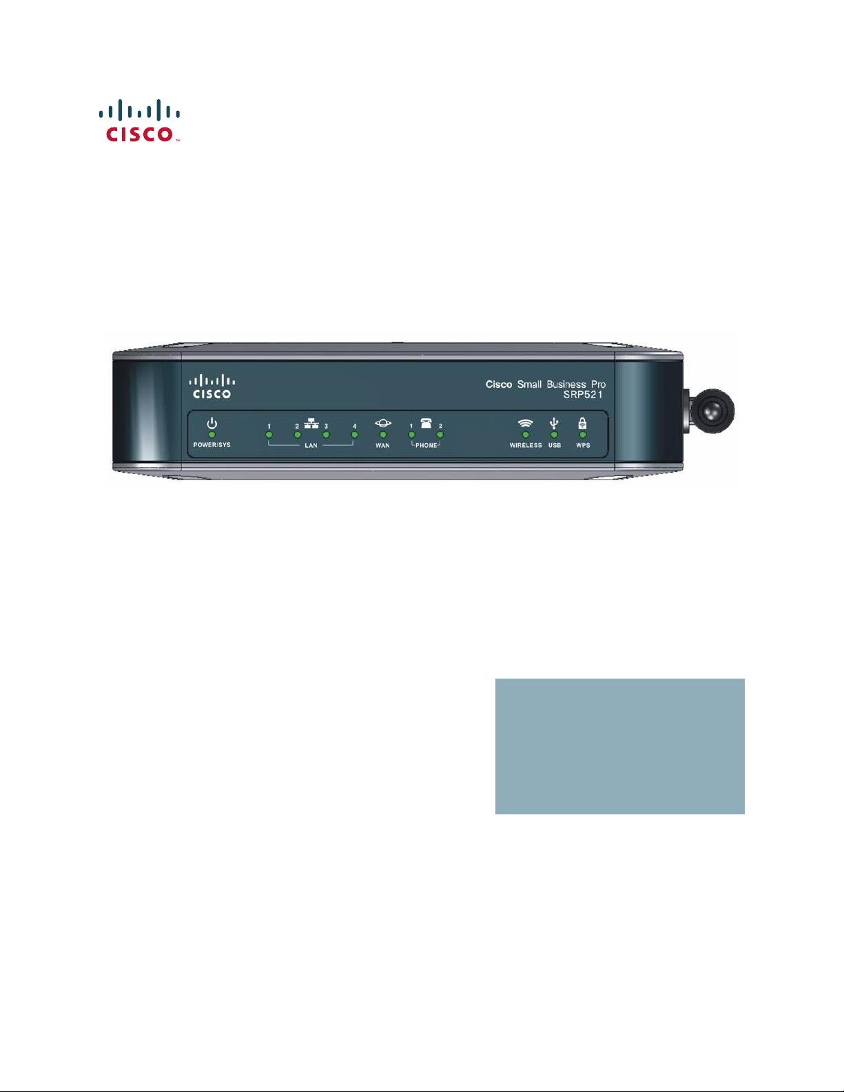
Feature Overview
Thank you for choosing the Cisco Small Business Pro SRP521Services Ready
Platform VoIP Gateway. The gateway has the features needed for small business.
Its WAN port and four LAN ports support 10/100 Mbps speeds, it has two ports to
connect to analog telephone Service (PSTN), and supports 802.11b/g/n wireless
networking.
Product Overview
The SRP521, a member of the Cisco Small Business Pro family, is a unified
communications solution for small businesses that provides voice, data, video,
security, and wireless capabilities.
With its web-based interface, the SRP521 is easy to setup and configure.
SRP 521 VoIP Gateway Administration Guide 7
Page 8
Introduction to the Gateway
Product Overview
SRP521 Front Panel
1
REVIEW DRAFT — CISCO CONFIDENTIAL
Cisco Small Business Pro
12 2143
LANPOWER/SYS WAN PHONE USB WPSWIRELESS
LED Description
POWER/SYS Solid green indicates that the SRP521 is powered on.
Slow green flash indicates that the SRP521 is booting.
LAN Ports 1 to 4 Solid green indicates link. Green flash indicates link
traffic.
WAN Solid green indicates link. Green flash indicates link
traffic.
WIRELESS Solid green indicates the radio is operational. Green flash
indicates wireless traffic.
SRP521
276377
USB Solid green indicates USB device is operational. Green
flash indicates device failure or unsupported device.
WPS Solid green indicates WiFi Protected Setup success.
Slow green flash indicates setup in progress. Fast green
flash indicates a setup error.
SRP 521 VoIP Gateway Administration Guide 8
Page 9
Introduction to the Gateway
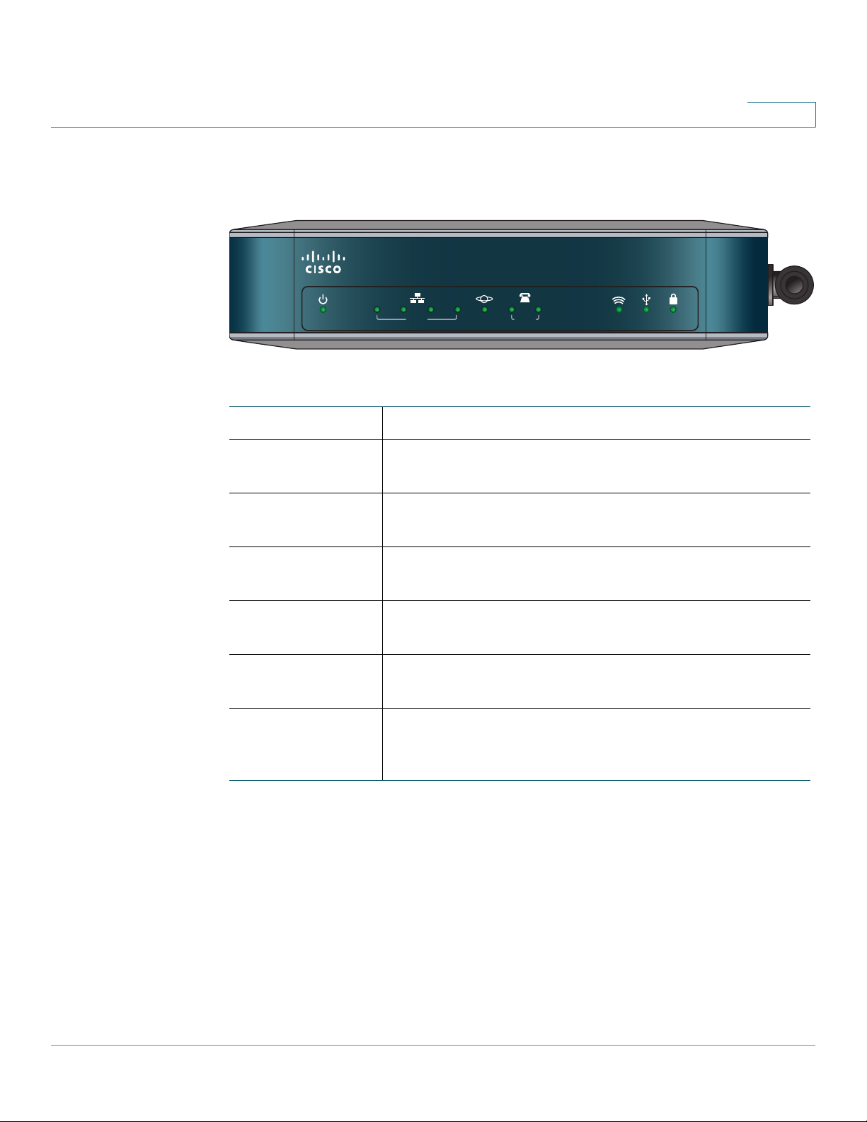
Product Overview
SRP521 Back Panel
1
REVIEW DRAFT — CISCO CONFIDENTIAL
FXO
Line
Port
21 1234
LINE (FXO)PHONE (FXS)
WAN
Port
LAN (10/100)WAN (10/100)
On/Off
Switch
12VDC
12V DC
Phone
Ports
Feature Description
PHONE Ports Use these ports to connect analog phones.
FXO LINE Port Use this port to connect to the Public Switched Telephone
Network (PSTN) which is the analog telephone service
network that traditional phone service uses.
LAN
Ports
Power
276375
WAN Port Use this port to connect the SRP521 to your WAN or DSL
Internet connection.
LAN Ports 1 to 4 Use these ports to connect to a network device.
On/Off Switch Use this switch to power the SRP521 on or off.
12 V DC Power Use this port to connect the power adapter.
SRP 521 VoIP Gateway Administration Guide 9
Page 10

Introduction to the Gateway
Product Overview
Side Panels
1
REVIEW DRAFT — CISCO CONFIDENTIAL
Reset
button
RESET
USB
connector
USB
276380
276381
Feature Description
RESET Button Press this button for 10 seconds to reset the SRP521.
USB Port Use this port to connect a compatible 3G USB device. For
a list of compatible 3G USB modems please check the
support community at cisco.com/go/smallbizsupport.
Antenna SRP521 Wi-Fi antenna.
SRP 521 VoIP Gateway Administration Guide 10
Page 11

Introduction to the Gateway
Product Overview
Top Vie w
1
REVIEW DRAFT — CISCO CONFIDENTIAL
276378
WPS Button
Feature Description
WPS Button To automatically configure wireless security for devices
that support Wi-Fi Protected Setup (WPS), press and hold
this button until the WPS LED blinks.
NOTE The device being configured by WPS should be
physically close to the SRP521 because Wi-Fi
power is reduced during the setup.
SRP 521 VoIP Gateway Administration Guide 11
Page 12

REVIEW DRAFT — CISCO CONFIDENTIAL
The Home Menu
This chapter describes how to view Quick Setup instructions and how to start the
Setup Wizard.
• Quick Setup Instructions, page 12
• Starting the Setup Wizard, page 12
2
Quick Setup Instructions
The Quick Setup page presents a summary of the steps required to setup the
gateway, secure your network, and provide personal network settings. Many of
the steps contains hyperlinks that quickly take you to that highlighted item.
STEP 1 Click Home on the tab and then click Quick Setup in the navigation pane. The
Quick Steup page appears.
STEP 2 Optionally, you can click a hyperlink to jump to that page.
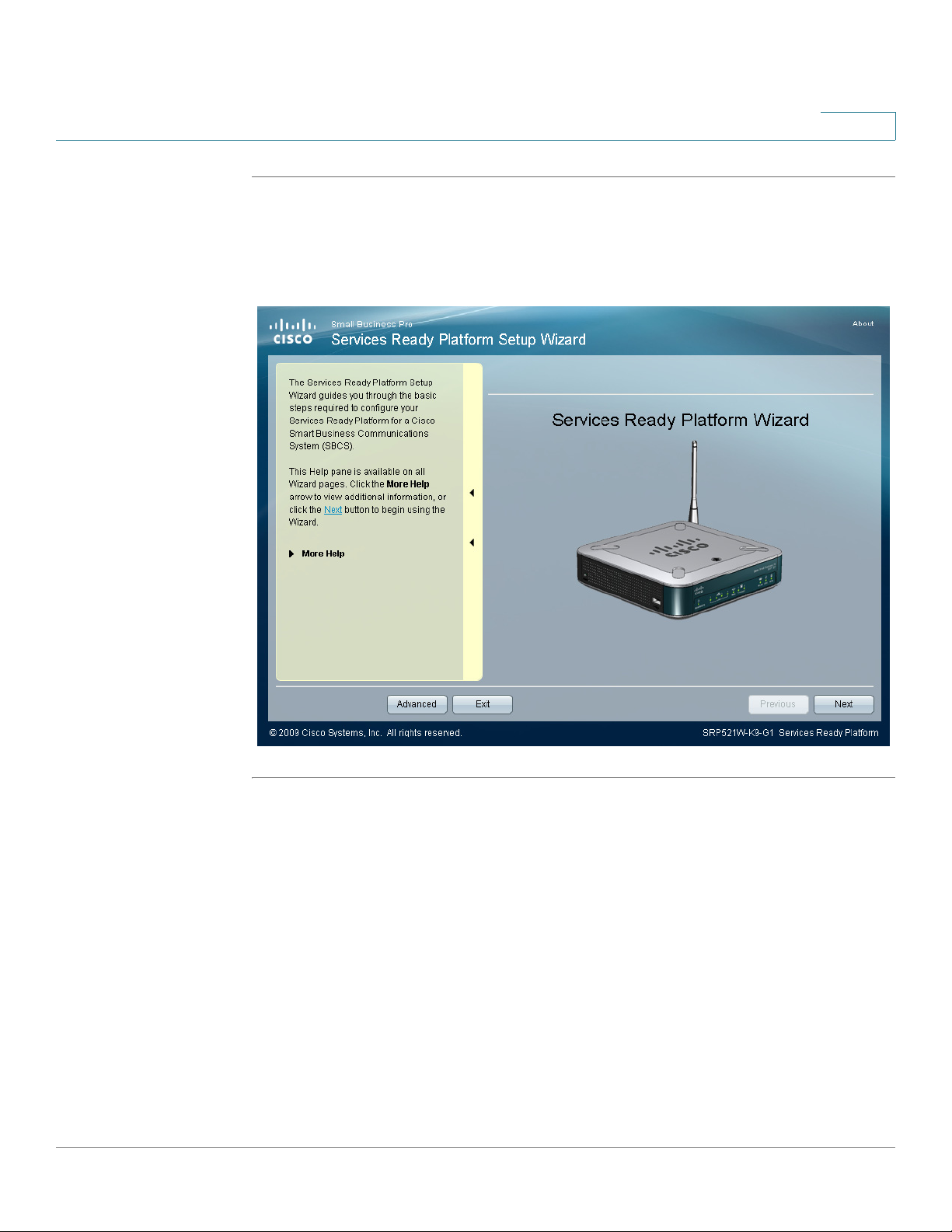
Starting the Setup Wizard
The Setup Wizard guides you through the basic steps required to configure your
Services Ready Platform for a Cisco Smart Business Communications System
(SBCS).
NOTE The Setup Wizard is helpful to configure your gateway the first time you install it.
SRP 521 VoIP Gateway Administration Guide 12
Page 13
The Home Menu
Starting the Setup Wizard
STEP 1 Click Home on the tab and then click SetupWizard in the navigation pane. The
STEP 2 Follow the instructions in the Setup Wizard to configure your gateway.
2
REVIEW DRAFT — CISCO CONFIDENTIAL
Setup Wizard page appears.
SRP 521 VoIP Gateway Administration Guide 13
Page 14

REVIEW DRAFT — CISCO CONFIDENTIAL
Setting up the Interfaces of the Gateway
You can use the Inteface Setup pages to setup the WAN, LAN, and Wireless LAN
interfaces.
• Setting up the WAN Interface, page 14
• Setting up the LAN Interface, page 22
• Setting up the Wireless LAN, page 29
3
• Using the Loopback Interface, page 45
Setting up the WAN Interface
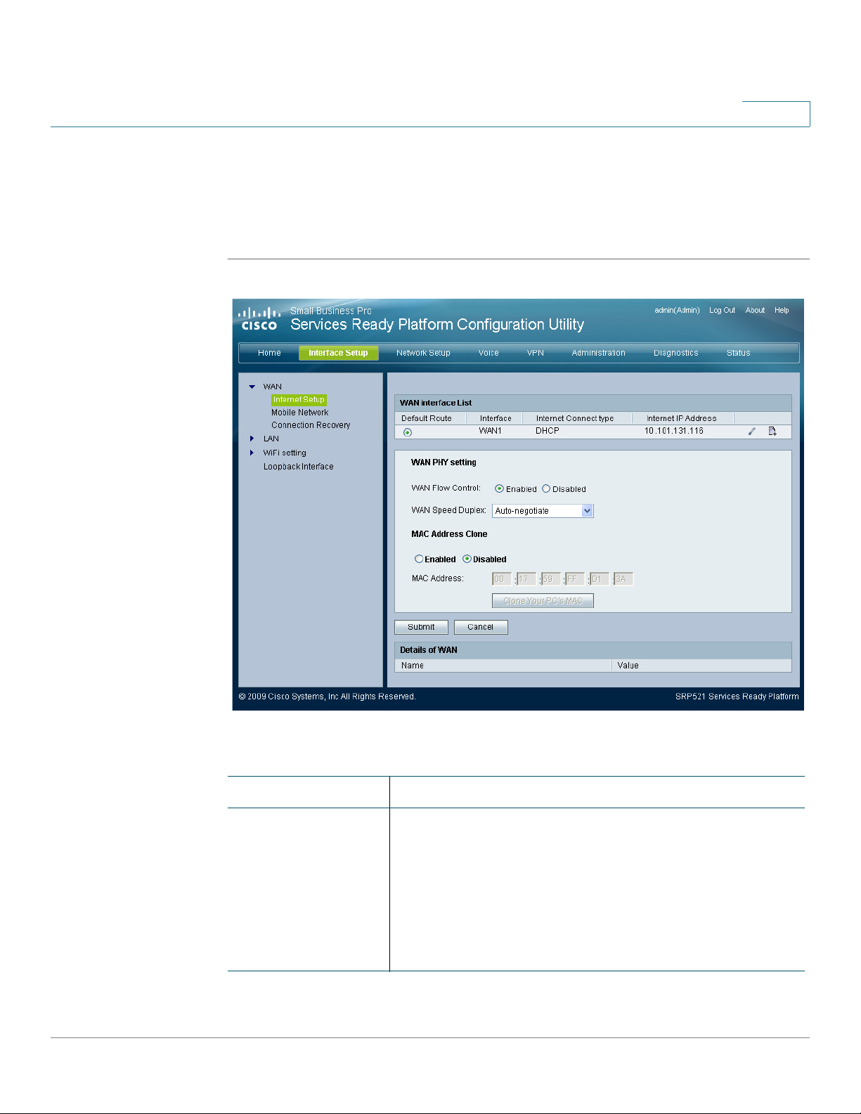
Internet Setup
The settings for WAN networking are set on these pages. In most cases, you can
configure the gateway and get it working properly by using only the settings on
these pages.
NOTE After you configure interfaces settings, you should set a new password for the
gateway using the Adminstration > Access Setting page. This precaution increases
security, protecting the gateway from unauthorized changes. All users who try to
access the web-based Configuration Utility will be prompted for the password of
the gateway.
STEP 1 Click Interface Setup on the tab and then click WAN in the navigation pane. The
Internet Setup page appears.
STEP 2 To add or edit interfaces in the WAN Interface List, click the add or edit icons.
STEP 3 Adjust WAN Phy Set tin gs as necessary.
SRP 521 VoIP Gateway Administration Guide 14
Page 15
Setting up the Interfaces of the Gateway
Setting up the WAN Interface
REVIEW DRAFT — CISCO CONFIDENTIAL
STEP 4 To clone a MAC address to the gateway, click Enabled and then enter a MAC
address. To clone the MAC address of your computer, click the Clone Your PC’s
MAC button.
STEP 5 Click Submit to save your settings.
3
Field Description
WAN Interface List The WAN Interface list which shows the physical link, its
protocol, and itsIP address if one exists. In each entry,
you can create new sub-interface by clicking the Add
Subinterface button or the Edit button.
If you have more than one sub-interface, you can choose
ether one as the default routing interface by selecting
the Default Route radio button.
SRP 521 VoIP Gateway Administration Guide 15
Page 16

3
Setting up the Interfaces of the Gateway
Setting up the WAN Interface
Field Description
WAN Flow Control WAN flow control. To set flow control for the WAN, select
Enabled and click Submit. The default setting is
Disabled.
WAN Speed Duplex WAN Speed Duplex mode. Selections are Auto-
negotiate, 10 Half, 10 Full, 100 Half and 100 Full. To set
WAN speed duplex mode, choose the mode and click
Submit.The default setting is Auto-negotiate.
MAC Address
Clone
Details of WAN The Details of WAN area shows information about your
A MAC address is a 12-digit code assigned to a unique
piece of hardware for identification purposes. Some
ISPs require that you to register a MAC address in order
to access the Internet. If you do not wish to re-register
the MAC address with your ISP, you may assign the
MAC address that you have currently registered with
your ISP to the gateway with the MAC Address Clone
feature. To clone your MAC address, select Enabled,
click Clone Your PC’s MAC, and click Submit. The
default value is Disabled.
WAN.
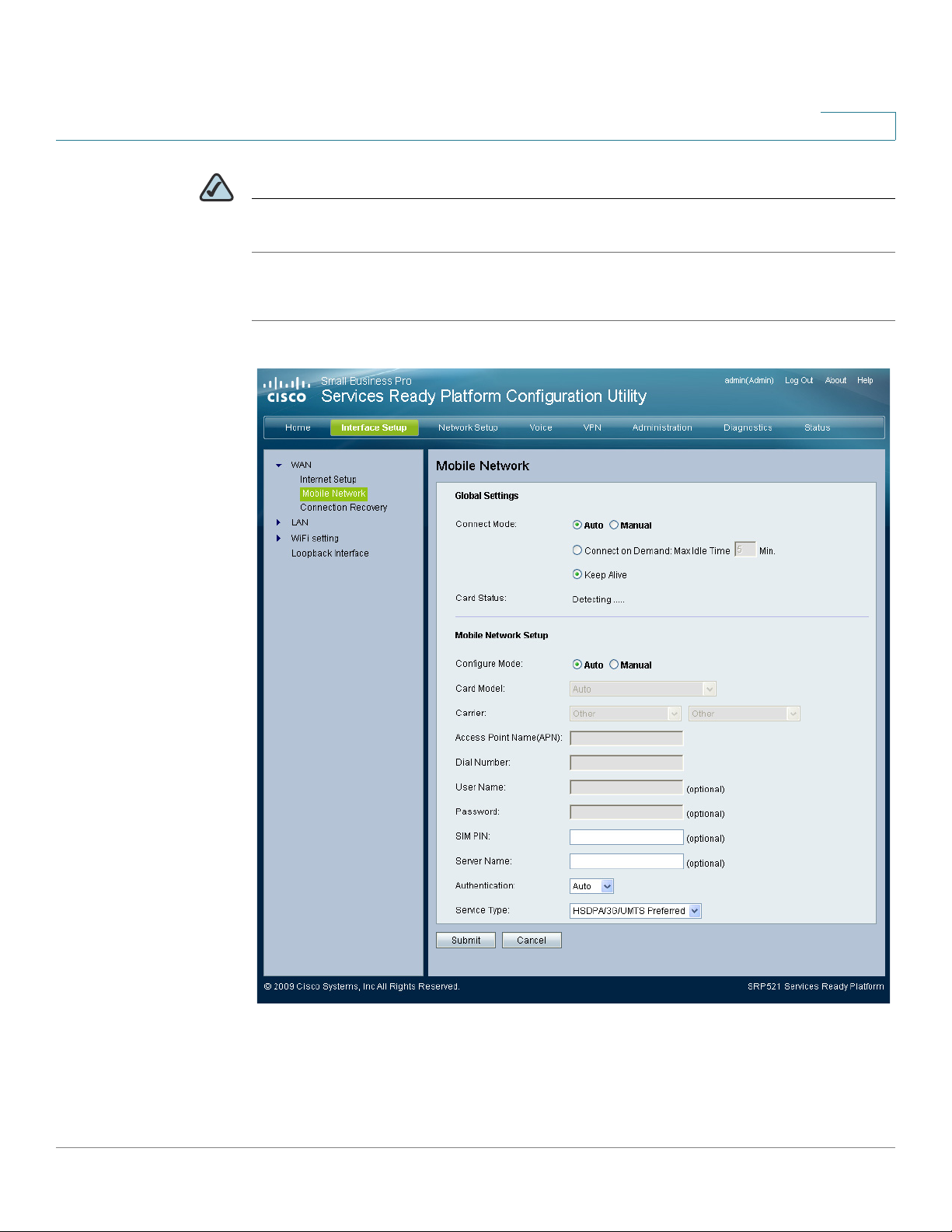
Mobile Network
You can configure your gateway to connect to a mobile network through the USB
interface. The gateway allows you to set the connect mode. You can configure an
automatic or manual connection. You also can use this page to view the current
connection status.
STEP 1 Click Interface Setup on the tab and then click Mobile Network in the navigation
pane. The Mobile Network page appears.
STEP 2 If necessary, change any global settings in the Global Settings area. The Card
Status field shows the status of your mobile card.
STEP 3 If necessary, change any mobile network settings in the Mobile Network Setup
area.
16 SRP 521 VoIP Gateway Administration Guide
Page 17
Setting up the Interfaces of the Gateway
Setting up the WAN Interface
REVIEW DRAFT — CISCO CONFIDENTIAL
NOTE You must click the Manual option in the Configure Mode field to manually setup your
mobile network card.
STEP 4 Click Submit to save your settings.
3
SRP 521 VoIP Gateway Administration Guide 17
Page 18

3
Setting up the Interfaces of the Gateway
Setting up the WAN Interface
Field Description
Connect Mode Auto or manual connect mode. Select Auto to enable
your modem to establish a connection automatically or
select Manual to connect or disconnect your modem
connection manually.
NOTE The Ethernet Connection Recovery and Interface
Connection Failover works only if the Connection
Mode is set to Auto. If you select Auto, you must
select Connect on Demand and Keep Alive. If you
select Connect on Demand option, you can
configure the gateway to terminate the Internet
connection after it has been inactive for a
specified period of time (Max Idle Time).
Connect on Demand enables the modem to
automatically re-establish a terminated connection
when a user attempts to access the Internet again. In the
Max Idle Time field, enter the number of minutes of
inactivity that can elapse before your Internet
connection terminates. The default is 5 minutes. The
gateway periodically checks your Internet connection. If
you are disconnected, then it will automatically reestablish your connection. To use this option, select
Keep Alive. In the Redial Period field, specify how often
you want the gateway to check the Internet connection.
The default is 30 seconds.
Card Status The status of the card. If your Connect Mode is Manual,
there will be a button that you can click to connect or
disconnect your Modem.
Configure Mode Select Auto to allow the gateway to automatically detect
which card model was inserted and which carrier is
available. Select Manual to set up the connection
manually. The default setting is Auto.
Card Model This field displays the data card model that is inserted in
the USB drive.
18 SRP 521 VoIP Gateway Administration Guide
Page 19

Setting up the Interfaces of the Gateway
Setting up the WAN Interface
REVIEW DRAFT — CISCO CONFIDENTIAL
Field Description
Carrier The mobile network service provider for the Internet
3
connection. This setting is required when you are using
HSDPA/UMTS/GPRS Internet service. Select the card
issue country from the first drop-down menu list, then
select the card issue provider from the second dropdown list.
Access Point Name
(APN)
Dial Number The dial number for the Internet connection. Enter the
User Name/
Password
SIM PIN The PIN code associated with your SIM card. Enter your
Server Name The name of the server for the Internet connection.
Authentication The type of authentication used by your service
Service Type Select the most commonly available type of mobile data
The Internet network to which the mobile device is
connecting to. Enter the access point name provided by
your mobile network service provider.
Dial Number provided by your mobile network service
provider.
Enter the user name and password provided by your
mobile network service provider.
SIM PIN number here.
provider. Select your authentication type, if you do not
know which type to use, use the default setting, Auto.
service connection based on your area service signal. If
your location supports only one mobile data service,
you may set up for enhance build up connection. The
first selection will always search for HSPDA/3G/UMTS
service or switch to GPRS automatically only when it is
available.
Connection Recovery
An Internet connection can be established via the WAN port or a wireless modem
plugged into the USB port. While both Ethernet and USB interfaces may be
connected, only one of them can be used to establish a link at a time. Whenever
the Internet connection fails, the gateway automatically attempts to bring up
SRP 521 VoIP Gateway Administration Guide 19
Page 20

3
Setting up the Interfaces of the Gateway
Setting up the WAN Interface
another connection on another interface. This feature is called
the Ethernet Internet connection recovers, the gateway automatically attempts to
bring back and recover the Ethernet Internet connection. This feature is called
Recovery
STEP 1 Click Interface Setup on the tab and then click Connection Recovery in the
navigation pane. The Connection Recovery page appears.
STEP 2 If necessary, enable the Ethernet Connection Recovery feature by clicking
Enabled. When this option is enabled, the gateway sets the ethernet interface to
the highest priority. Enabling this feature also enables the Interface Connection
Failover feature. Whenever the Internet connection fails, the gateway automatically
attempts to bring up the mobile network connection on the USB interface (if
available). Whenever the Ethernet Internet connection recovers, the gateway
automatically attempts to bring back and recover the Ethernet Internet connection.
NOTE Your Mobile Connection Mode must be set to Auto to use the Ethernet Connection
Recovery feature.
.
Failover
. Whenever
STEP 3 If necessary, enter an ethernet timeout value.
STEP 4 Choose a site on which to perform failover validation in the Failover Validation Site
area, either use the gateway or enter the IP address for a custom site.
STEP 5 If necessary, change the priority of the WAN interfaces by clicking the Up or Down
buttons.
STEP 6 Click Submit to save your settings.
20 SRP 521 VoIP Gateway Administration Guide
Page 21

Setting up the Interfaces of the Gateway
Setting up the WAN Interface
REVIEW DRAFT — CISCO CONFIDENTIAL
3
Field Description
Ethernet
Connection
Recovery
Interface
Connection Failover
Timeout The time interval at which the gateway detects the
This feature ensures that your Ethernet Internet
connection is always connected when available.
Failover detection works by detecting the physical
connection and/or presence of traffic on the Internet
link. If the link is idle, the gateway attempts to ping a
destination. If the ping does not reply, the gateway
assumes the link is down and attempts to fail over to
another interface.
status of the Internet connection. The default timeout
interval is 60 seconds.
SRP 521 VoIP Gateway Administration Guide 21
Page 22

3
Setting up the Interfaces of the Gateway
Setting up the LAN Interface
Field Description
Failover Validation
Site
WAN Interfaces This area provides information on current status of the
Setting up the LAN Interface
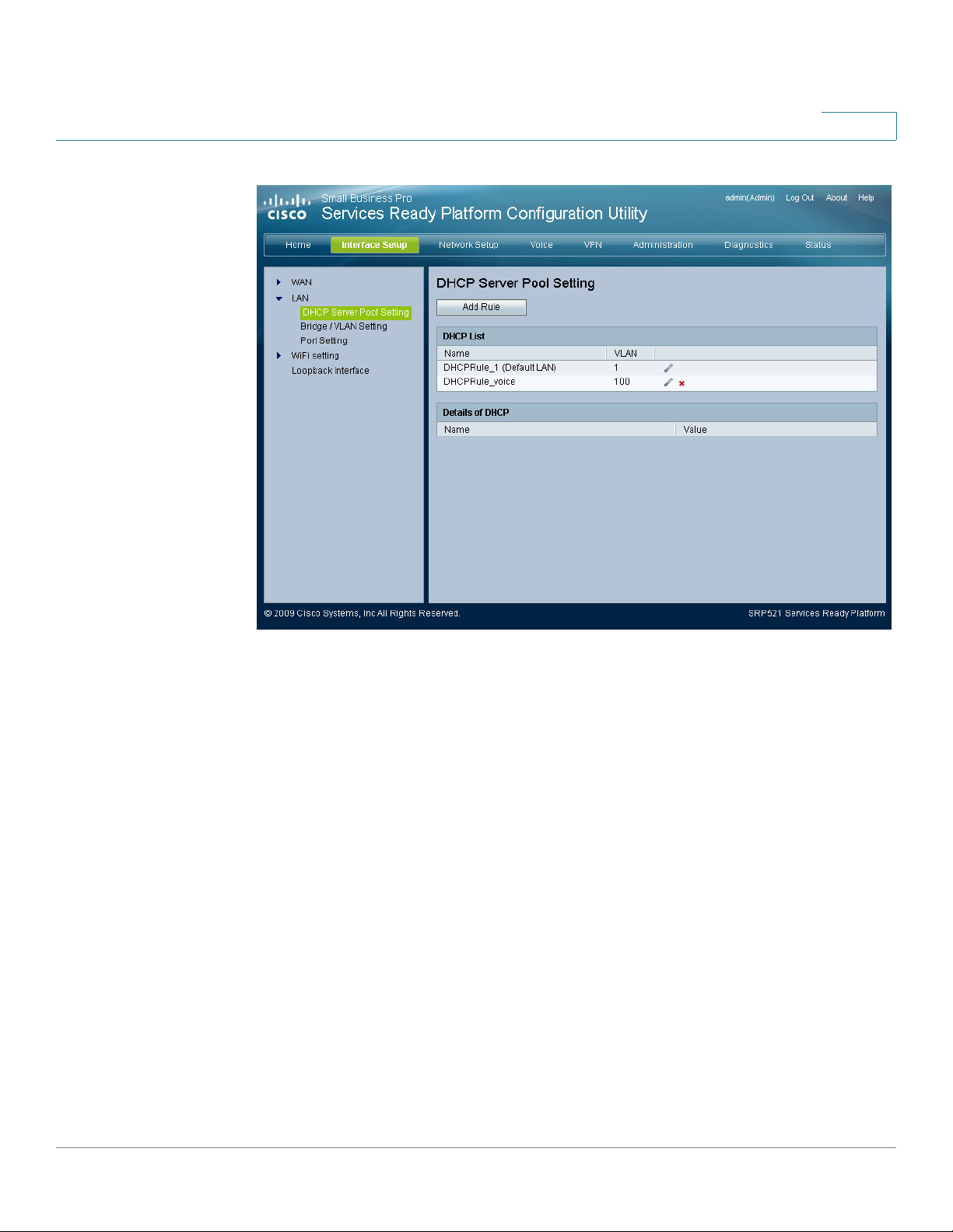
DHCP Server Pool Setting
DHCP Server Pool settings are configured on this page. After clicking Add Rule
button, you can create another DHCP Server Pool.
A ping target for the gateway to use to detect the status
of the Internet connection. By default the gateway pings
the Network Time Protocol (NTP) servers. You may
specify a different IP address as a target here.
Ethernet Internet connection and Mobile Network
connection. You can click the Status hyperlink to view
the details. You may also configure the interface priority
by clicking Up or Down. Note that the interface priority
setting is configurable only when Ethernet Connection
Recovery is disabled.
STEP 1 Click Interface Setup on the tab and then click LAN in the navigation pane. The
DHCP Server Pool Setting page appears.
STEP 2 You can edit or delete a DHCP entry by clicking the edit or delete icon.
STEP 3 Click Add Rule to open the DHCP Add page. From this page you can add a DHCP
entry.
STEP 4 Click Submit to save your settings.
22 SRP 521 VoIP Gateway Administration Guide
Page 23
Setting up the Interfaces of the Gateway
Setting up the LAN Interface
REVIEW DRAFT — CISCO CONFIDENTIAL
3
Click one of the items in the DHCP List. DHCP information displays in the Details of
DHCP table.
When you click Add Rule, the DHCP - Add page opens.
SRP 521 VoIP Gateway Administration Guide 23
Page 24

3
Setting up the Interfaces of the Gateway
Setting up the LAN Interface
Field Description
DHCP Name The DHCP Name.
Local IP Address/
Subnet Mask
DHCP Server The DHCP server status. DHCP is enabled by factory
WAN Interface The WAN Interface.
24 SRP 521 VoIP Gateway Administration Guide
The DHCP IP address and subnet mask as seen by
external users on the Internet (including your ISP).
default. If you already have a DHCP server, then select
Disable (no other DHCP features will be available).
Page 25

Setting up the Interfaces of the Gateway
Setting up the LAN Interface
REVIEW DRAFT — CISCO CONFIDENTIAL
Field Description
Option 66 None, Local TFTP Server, or Remote TFTP Server. The
DNS Proxy The DNS proxy relays DNS requests to the current
Starting IP Address Enter a value for the DHCP server to start with when
3
default value is None.
public network DNS server for the proxy, and replies as
a DNS resolver to the client device on the network. To
enable the DNS Proxy feature, select Enabled. The
default setting is Disabled.
issuing IP addresses. Because the default IP address is
192.168.15.1, the starting IP address must be
192.168.15.2 or greater, but smaller than 192.168.15.149.
The default starting IP address is 192.168.15.100.
Maximum DHCP
Users
IP Address Range The range of DHCP addresses is displayed here.
Client Lease Time Amount of time a network user will be allowed
Static DNS The Domain Name System (DNS) is how the Internet
WINS The Windows Internet Naming Service (WINS) manages
Enter the maximum number of PCs that you want the
DHCP server to assign IP addresses. This number
cannot be greater than 253. The default is 50.
connection to the gateway with their current dynamic IP
address. Enter the amount of time, in minutes, that the
user will be “leased” this dynamic IP address. After the
time is up, the user will be automatically assigned a new
dynamic IP address. The default is 0 minutes, which
means one day.
translates domain or website names into Internet
addresses or URLs. Your ISP will provide you with at
least one DNS server IP address. If you wish to use
another, type that IP address.
PCs interaction with the Internet. If you use a WINS
server, enter the IP address of the server here.
Otherwise, leave this field blank.
SRP 521 VoIP Gateway Administration Guide 25
Page 26
3
Setting up the Interfaces of the Gateway
Setting up the LAN Interface
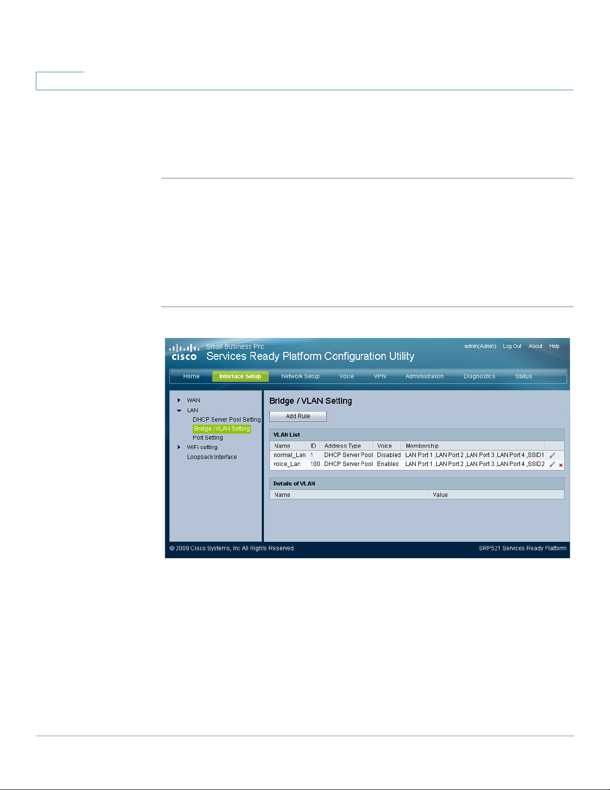
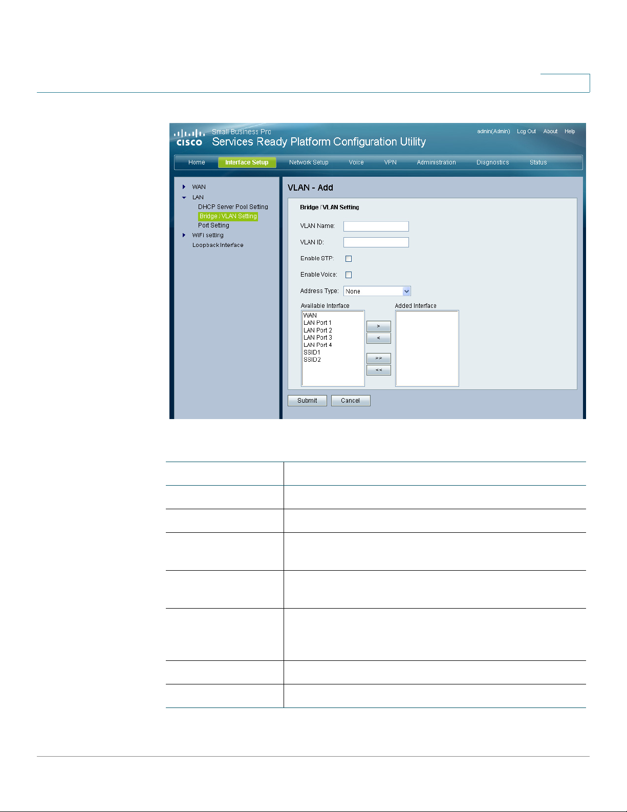
Bridge/VLAN Setting
Bridge / VLAN settings are configured on this page. After clicking Add Rule, you
can create another VLAN.
STEP 1 Click Interface Setup on the tab and then click LAN in the navigation pane. Click
Bridge / VLAN Setting. The Bridge / VLAN Setting page appears.
STEP 2 You can edit or delete a VLAN entry by clicking the edit or delete icon.
STEP 3 Click Add Rule to open the VLAN Add page. From this page you can add a VLAN
entry.
STEP 4 Click Submit to save your settings.
26 SRP 521 VoIP Gateway Administration Guide
Page 27
Setting up the Interfaces of the Gateway
Setting up the LAN Interface
REVIEW DRAFT — CISCO CONFIDENTIAL
3
Field Description
VLAN Name Bridge or VLAN name.
VLAN ID Bridge or VLAN ID.
Enable STP If you want to use Spanning Tree Protocol (STP), click
this box.
Enable Voice Click this box if you want to use voice. Only use this
option in VLAN mode.
Address Type Address type. Choices are None, Static IP Address,
Dynamic IP Address, and DHCP Server Pool. The default
value is None.
Available Interface The interfaces that are available to you.
Added Interface The interfaces that are selected.
SRP 521 VoIP Gateway Administration Guide 27
Page 28
3
Setting up the Interfaces of the Gateway
Setting up the LAN Interface
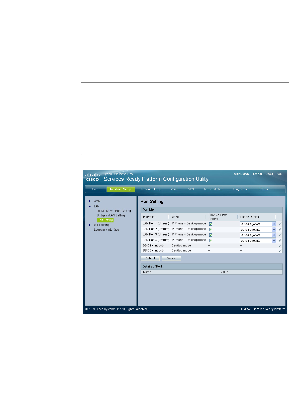
Port Setting
Port settings are configured on this page. You can also see details about the ports.
STEP 1 Click Interface Setup on the tab and then click LAN in the navigation pane. Click
Port Setting. The Port Setting page appears.
STEP 2 You can edit a port entry by clicking the edit icon. After you click the edit icon, the
Port Edit page opens. Make any necessary changes and click Submit to save your
settings.
STEP 3 If necessary, change the flow control or duplex speed settings for each interface.
STEP 4 Click Submit to save your settings.
28 SRP 521 VoIP Gateway Administration Guide
Page 29

Setting up the Interfaces of the Gateway
Setting up the Wireless LAN
REVIEW DRAFT — CISCO CONFIDENTIAL
Field Description
3
Enabled Flow
Control
Speed Duplex Network speed settings. The default setting is Auto-
Details of Port The Details of Port area shows information about your
Setting up the Wireless LAN
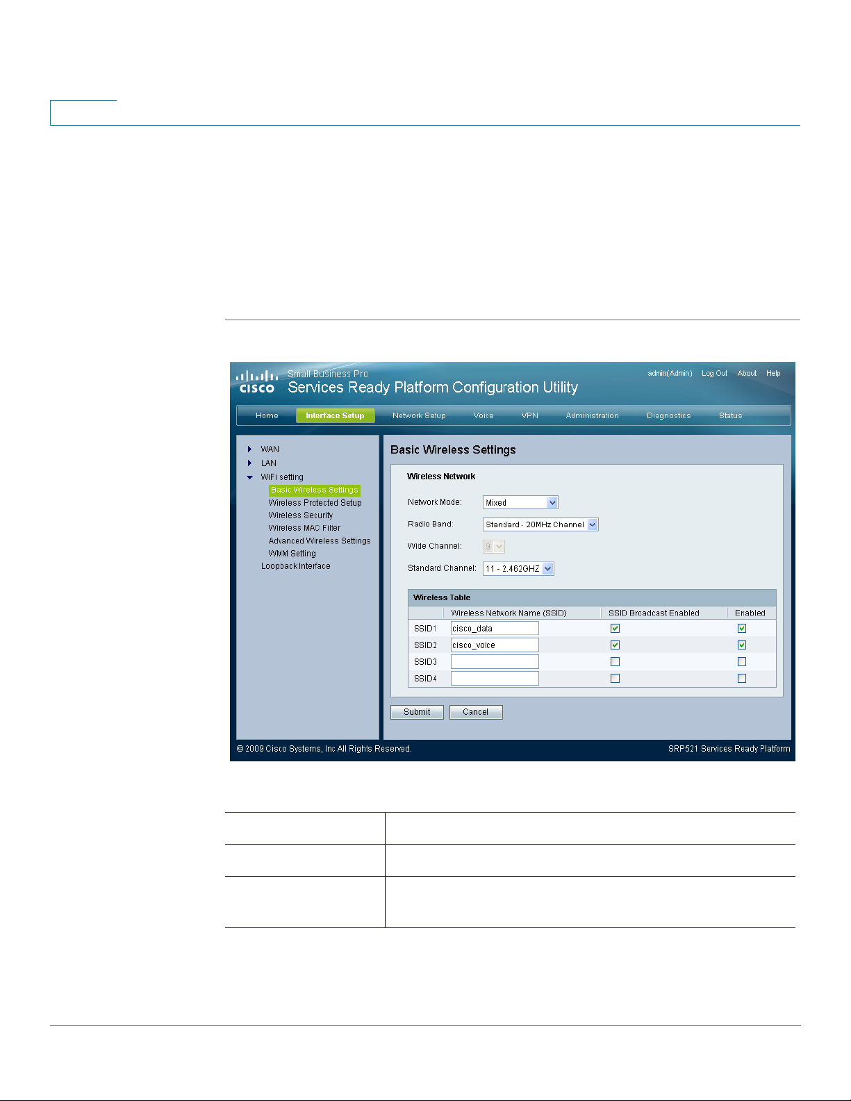
Basic Wireless Settings
The basic settings for wireless networking are set on this page.
There are two ways to configure the wireless network(s) of the gateway, manual
and Wi-Fi Protected Setup. To manually configure the wireless settings, use the
Basic Wireless Settings page.
LAN Flow control. To enable flow control, click the
Enable Flow Control box for the LAN interface and click
Submit. Flow control is enabled by default.
negotiate.
ports.
If you have client devices, such as wireless adapters, that support Wi-Fi Protected
Setup, then you can use Wi-Fi Protected Setup to automatically configure wireless
security for your wireless network(s). To use Wi-Fi Protected Setup, refer to your
wireless adapter's documentation.
STEP 1 Click Interface Setup on the tab and then click WiFi Setting in the navigation pane.
The Basic Wireless Settings page appears.
STEP 2 From the Network Mode menu, you can select the wireless standards running on
your network.
• If you have Wireless-N, Wireless-G, and Wireless-B devices in your network,
use the default setting, Mixed.
• If you have only Wireless-G and Wireless-B devices in your network, select
BG-Mixed. If you have only Wireless-N devices, select Wireless-N Only.
• If you have only Wireless-G devices, select Wireless-G Only.
SRP 521 VoIP Gateway Administration Guide 29
Page 30
3
Setting up the Interfaces of the Gateway
Setting up the Wireless LAN
• If you have only Wireless-B devices, select Wireless-B Only.
• If you do not have any wireless devices in your network, select Disabled.
STEP 3 From the Radio Band menu, you can select the wireless bandwidth on your
network. There are three options you can select: Auto, Standard - 20MHz Channel,
and Wide - 40MHz Channel.
STEP 4 Click Submit to save your settings.
Field Description
Network Mode The network mode. the default mode is Mixed.
Radio Band The bandwidth of the radio channel. The default is
Standard - 20MHz Channel.
30 SRP 521 VoIP Gateway Administration Guide
Page 31

Setting up the Interfaces of the Gateway
Setting up the Wireless LAN
REVIEW DRAFT — CISCO CONFIDENTIAL
Field Description
Wide Channel If you selected Wide - 40MHz Channel for the Radio
Standard Channel If you selected Wide - 40MHz Channel or Standard -
SSID1-4 The SSID is the network name shared among all
3
Band setting, this setting will be available for your
primary Wireless-N channel. Select any channel from
the drop-down menu.
20MHz Channel for the Radio Band setting, then this
setting will be available. Select the channel for WirelessN, Wireless-G, and Wireless-B networking. If you
selected Wide - 40MHz Channel for the Radio Band
setting, then the Standard Channel will be a secondary
channel for Wireless-N. The default value is channel 11.
devices in a wireless network. The gateway can
support up to four wireless networks. By default, first
and second wireless network is enabled, and you can
create the other wireless network names.
Wireless Network
Name (SSID)
SSID Broadcast
Enabled
Enabled To enable the wireless network, select the check box. To
The first default wireless network uses the name
“cisco_data” which is connected to the default VLAN.
The second default wireless network uses the name
“cisco_voice” which is connected to the voip VLAN. To
rename the default wireless network, enter a unique
Wireless Network Name, which is case-sensitive and
must not exceed 32 characters (use any of the
characters on the keyboard).
When wireless clients survey the local area for wireless
networks to associate, they detect the SSID broadcast
by the gateway. If you want to broadcast the SSID, keep
the check box selected. If you do not want to broadcast
the SSID, deselect the check box.
disable the wireless network, deselect the check box.
SRP 521 VoIP Gateway Administration Guide 31
Page 32

3
Setting up the Interfaces of the Gateway
Setting up the Wireless LAN
Wireless Protected Setup
Wi-Fi Protected Setup is a feature that makes it easy to set up your wireless
network. If you have client devices, such as wireless adapters, that support Wi-Fi
Protected Setup, then you can use Wi-Fi Protected Setup.
STEP 1 Click Interface Setup on the tab and then click WiFi Setting in the navigation pane.
Click Wireless Protected Setup. The Wireless Protected Setup page appears.
STEP 2 From Select a SSID menu, choose the SSID beacon interval and RTS threshold
settings you want to configure.
STEP 3 In the WPS field, select Disabled if you do not want to use the WiFi Protected
Setup.
NOTE There are three methods available to configure your WiFi settings using WPS. Use
the method below that applies to the client device you are configuring.
WPS Method 1
Use this method if your client device has a Wi-Fi Protected Setup button.
STEP 1 Click or press the Wi-Fi Protected Setup button on the client device.
STEP 2 Click the Wi-Fi Protected Setup button on this page.
STEP 3 After the client device has been configured, click OK. Then refer back to your
client device or its documentation for further instructions.
WPS Method 2
Use this method if your client device has a Wi-Fi Protected Setup PIN number.
STEP 1 Enter the PIN number in the field on this page.
STEP 2 Click Register.
32 SRP 521 VoIP Gateway Administration Guide
Page 33

Setting up the Interfaces of the Gateway
Setting up the Wireless LAN
REVIEW DRAFT — CISCO CONFIDENTIAL
STEP 3 After the client device has been configured, click OK. Then refer back to your
client device or its documentation for further instructions.
WPS Method 3
Use this method if your client device asks for the PIN number of the gateway.
STEP 1 Enter the PIN number listed on this page. (It is also listed on the label on the bottom
of the gateway.)
STEP 2 After the client device has been configured, click OK. Then refer to your client
device or its documentation for further instructions.
3
The Wi-Fi Protected Setup Status, Network Name (SSID), Security, Encryption, and
Passphrase are displayed at the bottom of the page.
SRP 521 VoIP Gateway Administration Guide 33
Page 34

3
Setting up the Interfaces of the Gateway
Setting up the Wireless LAN
Field Description
Select a SSID Choose the SSID for the wireless network that you want
to configure. The default is SSID1.
WPS WiFi Protected Setup (WPS) option. The default is
Enabled.
34 SRP 521 VoIP Gateway Administration Guide
Page 35

Setting up the Interfaces of the Gateway
Setting up the Wireless LAN
REVIEW DRAFT — CISCO CONFIDENTIAL
Wireless Security
The Wireless Security page configures the security of your wireless network(s).
The gateway supports the following wireless security mode options: WPA
Personal, WPA Enterprise, WPA2 Personal, WPA2 Enterprise, RADIUS and WEP.
(WPA stands for Wi-Fi Protected Access, which is a security standard stronger
than WEP encryption. WEP stands for Wired Equivalent Privacy.)
STEP 1 Click Interface Setup on the tab and then click WiFi Setting in the navigation pane.
Click Wireless Security. The Wireless Security page appears.
STEP 2 From the Select a SSID menu, choose the SSID for the wireless network that you
want to configure.
STEP 3 Select the security method for your wireless network. If you do not want to use
wireless security, use the default setting, Disabled (not recommended).
3
STEP 4 If you selected a security mode, fill in the fields for the security mode that you
chose.
STEP 5 Click Submit to save your settings.
Field Description
Select a SSID The SSID to which the securithy setting is applied. The
default is SSID1.
SRP 521 VoIP Gateway Administration Guide 35
Page 36

3
Setting up the Interfaces of the Gateway
Setting up the Wireless LAN
Field Description
Security Mode The security mode for the selected SSID.
WEP WEP is a basic encryption method, which is not as
secure as WPA.
Encryption The level of WEP encryption, 64 bits 10 hex digits or
128 bits 26 hex digits. The default is 64 bits 10 hex
digits.
Passphrase To automatically generate WEP keys, type a
passphrase, then click Generate.
Key 1-4 If you did not enter a Passphrase, you can enter the WEP
key(s) manually.
TX Key The TX (Transmit) Key to use. The default value is 1.
WPA Personal
WPA Algorithms WPA supports two encryption methods, TKIP and AES,
with dynamic encryption keys. Select the type of
algorithm, AES or TKIP. The default is TKIP.
WPA Shared Key The Passphrase of 8-63 characters.
Group Key Renewal The Key Renewal period, which instructs the gateway
how often it should change the encryption keys. The
default Group Key Renewal period is 3600 seconds.
WPA2 Personal
WPA Algorithms WPA2 supports two encryption methods, AES and
TKIP+AES, with dynamic encryption keys. Select the
type of algorithm, AES, or TKIP+AES. The default is
TKIP+AES.
WPA Shared Key The Passphrase of 8-63 characters.
Group Key Renewal The Key Renewal period, which instructs the gateway
how often it should change the encryption keys. The
default Group Key Renewal period is 3600 seconds.
36 SRP 521 VoIP Gateway Administration Guide
Page 37

Setting up the Interfaces of the Gateway
Setting up the Wireless LAN
REVIEW DRAFT — CISCO CONFIDENTIAL
Field Description
WPA Enterprise This option features WPA used in coordination with a
WPA Algorithms WPA supports two encryption methods, TKIP and AES,
3
RADIUS server. If you have two RADIUS servers, you
can select one to be the primary server, and the
secondary server can be a backup server. (This option
should only be used when a RADIUS server is
connected to the gateway.)
with dynamic encryption keys. Select the type of
algorithm, AES or TKIP. The default is TKIP.
RADIUS Server
Address
RADIUS Port The port number of the RADIUS server. The default
Shared Secret The key shared between the gateway and the server.
RADIUS Server
Address
RADIUS Port The port number of the RADIUS server.
Shared Secret The key shared between the gateway and the server.
Key Renewal
Timeo ut
WPA2 Enterprise This option features WPA2 used in coordination with a
The IP Address of the RADIUS server.
value is 1812.
The IP address of the RADIUS server.
The Key Renewal period, which instructs the gateway
how often it should change the encryption keys. The
default Key Renewal period is 3600 seconds.
RADIUS server. If you have two RADIUS servers, you
can select one to be the primary server, and the
secondary server can be a backup server. (This option
should only be used when a RADIUS server is
connected to the gateway.)
WPA Algorithms WPA2 supports two encryption methods, TKIP and AES,
with dynamic encryption keys. Select the type of
algorithm, AES or TKIP or AES. The default is TKIP or
AES.
Primary RADIUS Server
RADIUS Server The IP address of the RADIUS server.
SRP 521 VoIP Gateway Administration Guide 37
Page 38

3
Setting up the Interfaces of the Gateway
Setting up the Wireless LAN
Field Description
RADIUS Port The port number of the RADIUS server. The default
value is 1812.
Shared Secret The key shared between the gateway and the server.
Secondary RADIUS Server
RADIUS Server
Address
RADIUS Port The port number of the RADIUS server.
Shared Secret The key shared between the gateway and the server.
Key Renewal
Time out
RADIUS This option features WEP used in coordination with a
TX Key Select which TX (Transmit) Key to use. The default is 1.
The IP Address of the RADIUS server.
Enter a Key Renewal period, which instructs the
gateway how often it should change the encryption
keys. The default Key Renewal period is 3600 seconds.
RADIUS server. If you have two RADIUS servers, you
can select one to be the primary server, and the
secondary server can be a backup server. (This option
should only be used when a RADIUS server is
connected to the gateway.)
Wireless MAC Filter
You can control access to your wireless network by specifying the MAC
addresses of the wireless devices that are permitted access or are blocked.
STEP 1 Click Interface Setup on the tab and then click WiFi Setting in the navigation pane.
Click Wireless MAC Filter. The Wireless MAC Filter page appears.
STEP 2 From the Select a SSID menu, choose the MAC filter settings to apply to the SSID.
STEP 3 To filter wireless users by MAC Address, either permitting or blocking access,
select Enabled. If you do not wish to filter users by MAC Address, use the default
setting, Disabled.
STEP 4 In the Access Restriction area, select either Prevent or Permit.
38 SRP 521 VoIP Gateway Administration Guide
Page 39

Setting up the Interfaces of the Gateway
Setting up the Wireless LAN
REVIEW DRAFT — CISCO CONFIDENTIAL
STEP 5 If the Wireless MAC Filter option is enabled, you can click the Show Client List
button to open the Wireless Client List page. This page shows computers and
other devices on the wireless network. The list can be sorted by Client Name,
Interface, IP Address, MAC Address, and Status.
STEP 6 Select Save to MAC Address Filter List for any device you want to add to the list.
Then click Add. To retrieve the most up-to-date information, click Refresh. To exit
this page and return to the Wireless MAC Filter page, click Close.
STEP 7 Click Submit to save your settings.
3
SRP 521 VoIP Gateway Administration Guide 39
Page 40

3
Setting up the Interfaces of the Gateway
Setting up the Wireless LAN
Field Description
Select a SSID The MAC filter settings to apply to the SSID. The default
is SSID1.
Enabled/Disabled The option to filter wireless users by MAC Address.
Access Restriction
Prevent Select this option to prevent devices with the MAC
address in the table from accessing the wireless
network. This button is selected by default.
Permit Select this option to allow devices with the MAC
address in the table to access the wireless network.
This button is not selected by default.
Show Client List This button give you access to the Wireless Client List
page. This page shows computers and other devices on
the wireless network. The list can be sorted by Client
Name, Interface, IP Address, MAC Address, and Status.
MAC Address Table
01-32 The MAC addresses of the devices whose wireless
access you want to block or allow.
Advanced Wireless Settings
This feature is used to set up the advanced wireless functions of the gateway.
These settings should be adjusted only by an expert administrator; incorrect
settings can reduce wireless performance.
STEP 1 Click Interface Setup on the tab and then click WiFi Setting in the navigation pane.
Click Advanced Wireless Settings. The Advanced Wireless page appears.
STEP 2 From the Select a SSID menu, choose the beacon interval and RTS threshold
settings to apply to the SSID.
STEP 3 Enter a value in the RTS Threshold field. If you encounter inconsistent data flow,
enter only minor reductions. The default value of 2346 is recommended.
40 SRP 521 VoIP Gateway Administration Guide
Page 41

Setting up the Interfaces of the Gateway
Setting up the Wireless LAN
REVIEW DRAFT — CISCO CONFIDENTIAL
If a network packet is smaller than the preset RTS threshold size, the RTS/CTS
mechanism will not be enabled. The gateway sends Request to Send (RTS)
frames to a particular receiving station and negotiates the sending of a data frame.
After receiving an RTS, the wireless station responds with a Clear to Send (CTS)
frame to acknowledge the right to begin transmission.
STEP 4 Change any settings in the Advanced Wireless for group SSID area.
STEP 5 Click Submit to save your settings.
3
Field Description
Advanced Wireless for separate SSID
Select a SSID The beacon interval and RTS threshold settings to apply
to the SSID. The default is SSID1.
SRP 521 VoIP Gateway Administration Guide 41
Page 42

3
Setting up the Interfaces of the Gateway
Setting up the Wireless LAN
Field Description
RTS Threshold The RTS threshold value. The default value is 2346.
Advanced Wireless for group SSID
AP Isolation This option isolates all wireless clients and wireless
devices on your network from each other. Wireless
devices can communicate with the gateway but not with
each other. To use this function, select Enabled. AP
Isolation is disabled by default.
Authentication Type The default is set to Auto, which allows either Open
System or Shared Key authentication to be used. With
Open System authentication, the sender and the
recipient do NOT use a WEP key for authentication. With
Shared Key authentication, the sender and recipient use
a WEP key for authentication. Select Shared Key to only
use Shared Key authentication.
Basic Rate The Basic Rate setting is not actually one rate of
transmission but a series of rates at which the gateway
can transmit. The gateway advertises its Basic Rate to
the other wireless devices in your network, so they
know which rates will be used. The gateway will also
advertise that it will automatically select the best rate for
transmission. The default setting is Default, when the
gateway can transmit at all standard wireless rates (1-2
Mbps, 5.5 Mbps, 11 Mbps, 18 Mbps, and 24 Mbps).
Other options are 1-2 Mbps, for use with older wireless
technology, and All, when the gateway can transmit at all
wireless rates. The Basic Rate is not the actual rate of
data transmission. If you want to specify the gateway's
rate of data transmission, configure the Transmission
Rate setting.
Transmission Rate The rate of data transmission should be set depending
on the speed of your wireless network. You can select
from a range of transmission speeds, or you can select
Auto to have the gateway automatically use the fastest
possible data rate and enable the Auto-Fallback feature.
Auto-Fallback will negotiate the best possible
connection speed between the gateway and a wireless
client. The default is Auto.
42 SRP 521 VoIP Gateway Administration Guide
Page 43

Setting up the Interfaces of the Gateway
Setting up the Wireless LAN
REVIEW DRAFT — CISCO CONFIDENTIAL
Field Description
N Transmission Rate The rate of data transmission should be set depending
3
on the speed of your Wireless-N networking. You can
select from a range of transmission speeds, or you can
select Auto to have the gateway automatically use the
fastest possible data rate and enable the Auto-Fallback
feature. Auto-Fallback will negotiate the best possible
connection speed between the gateway and a wireless
client. The default is Auto.
CTS Protection
Mode
DTIM Interval This value, between 1 and 255, indicates the interval of
Fragmentation
Threshold
The gateway will automatically use CTS (Clear-To-Send)
Protection Mode when your Wireless-N and Wireless-G
products are experiencing severe problems and are not
able to transmit to the gateway in an environment with
heavy 802.11b traffic. This function boosts the
gateway's ability to catch all Wireless-N and Wireless-G
transmissions but will severely decrease performance.
The default is Auto.
the Delivery Traffic Indication Message (DTIM). A DTIM
field is a countdown field informing clients of the next
window for listening to broadcast and multicast
messages. When the gateway has buffered broadcast
or multicast messages for associated clients, it sends
the next DTIM with a DTIM Interval value. Its clients hear
the beacons and awaken to receive the broadcast and
multicast messages. The default value is 1.
This value specifies the maximum size for a packet
before data is fragmented into multiple packets. If you
experience a high packet error rate, you may slightly
increase the Fragmentation Threshold. Setting the
Fragmentation Threshold too low may result in poor
network performance. Only minor reduction of the
default value is recommended. In most cases, it should
remain at its default value of 2344.
Beacon Interval The Beacon Interval value indicates the frequency
interval of the beacon. A beacon is a packet broadcast
by the gateway to synchronize the wireless network.
Enter a value between 20 and 65,535 milliseconds. The
default value is 100.
SRP 521 VoIP Gateway Administration Guide 43
Page 44

3
Setting up the Interfaces of the Gateway
Setting up the Wireless LAN
Field Description
Power Control The WiFi output power from the gateway. From this
drop-down menu, choose High, Middle, or Low value to
cover a range of the wireless network. The default is
High.
WMM Setting
The gateway features WMM Support. The No Acknowledgement feature is
available only when the WMM Support feature is enabled.
STEP 1 Click Interface Setup on the tab and then click WiFi Setting in the navigation pane.
Click WMM Setting. The WMM Setting page appears.
STEP 2 If you have other devices on your network that support WMM Support, you can
select Enabled for the WMM Support option.
STEP 3 In the No Ackowledgement option, select Enabled to disable the
acknowledgement feature, so the gateway will not resend data if an error occurs.
STEP 4 Click Submit to save your settings.
44 SRP 521 VoIP Gateway Administration Guide
Page 45

Setting up the Interfaces of the Gateway
Using the Loopback Interface
REVIEW DRAFT — CISCO CONFIDENTIAL
Field Description
WMM Support If you have other devices on your network that support
3
WMM Support, select Enabled. Otherwise, use the
default setting, Disabled.
No
Acknowledgement
Select Enabled to disable the acknowledgement
feature, so the gateway will not resend data if an error
occurs. Otherwise, use the default setting, Disabled.
Using the Loopback Interface
The Loopback Interface is set on this page. It only allows two loopback interfaces.
STEP 1 Click Interface Setup on the tab and then click Loopback in the navigation pane.
The Loopback page appears.
STEP 2 Click on the loopback icon to change the IP address and subnet mask for each
loopback interface. The Loopback Interface page opens.
STEP 3 Enter the IP Address and Subnet Mask for each interface.
STEP 4 Click Submit to save your settings.
SRP 521 VoIP Gateway Administration Guide 45
Page 46

3
Setting up the Interfaces of the Gateway
Using the Loopback Interface
Field Description
IP Address/Subnet
Mask
The IP address and subnets for the loopback interfaces.
46 SRP 521 VoIP Gateway Administration Guide
Page 47

REVIEW DRAFT — CISCO CONFIDENTIAL
Configuring the Network
This chapter describes how to configure the network including static routing, NAT,
QoS, the firewall, PPPoE, DDNS, IGMP, UPnP, and CDP.
• Static Routing, page 47
• NAT, page 50
• QoS, page 56
4
Static Routing
• Firewall, page 59
• PPPoE Relay, page 64
• DDNS, page 65
• IGMP, page 69
• UPnP, page 70
• CDP Setting, page 71
These features are used to set up advanced functions of the gateway. Dynamic
Routing automatically adjusts how packets travel on your network. Static Routing
sets up a fixed route to another network destination.
Static Route Rule
The settings for Static Route Rule are set on this page. It shows the current static
routing list and details of the selected route.
STEP 1 Click Network Setup on the tab and then click Routing in the navigation pane. The
Static Route Rule page appears.
STEP 2 Click Add Rule. The Static Routing Add page opens.
SRP 521 VoIP Gateway Administration Guide 47
Page 48

4
Configuring the Network
Static Routing
STEP 3 Enter a static route name, destination IP address/subnet mask, and gateway IP
address.
STEP 4 Click Submit to save your settings.
After clicking the Add Rule button, the Static Routing Add page opens.
48 SRP 521 VoIP Gateway Administration Guide
Page 49

Configuring the Network
Static Routing
4
REVIEW DRAFT — CISCO CONFIDENTIAL
Field Description
Enter Route Name The Static Routing Name
Destination LAN IP The address of the network or host to which you want to
assign a static route.
Subnet Mask The Subnet Mask. The Subnet Mask determines which
portion of an IP address is the network portion, and
which portion is the host portion.
Gateway The IP address of the gateway device that allows for
contact between the gateway and the network or host.
Interface Interface to use for static routing.
Show Routing Table Clicking this button shows the current routing table.
Click Hide Routing Table to hide the routing table.
RIP
Dynamic Routing (RIP) enables the gateway to automatically adjust to physical
changes in the network layout and exchange routing tables with other gateways.
The gateway determines the route of network packets based on the fewest
number of hops between the source and destination.
STEP 1 Click Network Setup on the tab and then click RIP in the navigation pane. The RIP
page appears.
STEP 2 To enable the Dynamic Routing feature for the Internet side, select Enabled. To
disable the Dynamic Routing feature for all data transmissions, use the default
setting, Disabled.
STEP 3 Select the RIP version.
STEP 4 Set RIP timer values.
STEP 5 In the RIP List, select the Interface that you want to enable the RIP function. Or you
can add the network address to join the RIP.
STEP 6 Click Submit to save your settings.
SRP 521 VoIP Gateway Administration Guide 49
Page 50

4
Configuring the Network
NAT
NAT
Intervlan Routing
This page allows you to enable or disable intervlan routing. When enabled, this
feature enables hosts that belong to different VLANs to route to each other. If
disabled, communications between hosts that belong to different VLAN are
blocked. Select either Enabled or Disabled and then Submit to enable or disable
Intervlan routing.
Setting
The Routing page allows you to enable or disable NAT routing, which allows the
gateway to host your network connection to the Internet (Enabled mode is
recommended for most users).
50 SRP 521 VoIP Gateway Administration Guide
Page 51

Configuring the Network
NAT
STEP 1 Click Network Setup on the tab and then click NAT in the navigation pane. Click
STEP 2 To enable NAT, select Enabled.
STEP 3 Click Submit to save your settings.
STEP 1 Click Network Setup on the menu bar and then click NAT. Click Single Port
4
REVIEW DRAFT — CISCO CONFIDENTIAL
Setting. The Routing page appears.
Single Port Forwarding
The settings for Single Port Forwarding are set on this page. It shows the current
port forwarding list and details of the selected route.
Forwarding. The Single Port Forwarding page appears.
STEP 2 Click Add Rule. The Single Port Forwarding page opens.
STEP 3 Select an application from the list.
STEP 4 Enter a name of the application.
STEP 5 Select a WAN interface.
STEP 6 Choose an external and internal port.
STEP 7 Select a protocol.
STEP 8 Enter the IP address of the server that should receive the requests.
STEP 9 Click Enabled to enable the applications you have defined.
STEP 10 Click Submit to save your settings.
SRP 521 VoIP Gateway Administration Guide 51
Page 52

4
Configuring the Network
NAT
Field Description
Application Name A list of applications. Select an application from the list.
Enter a Name The name of the application.
Wan Interface Name The WAN Interface.
External Port The external port number used by the server or Internet
application. Check with the Internet application
documentation for more information.
Internal Port The internal port number used by the server or Internet
application. Check with the Internet application
documentation for more information.
Protocol Select the protocol TCP or UDP, or select Both.
IP Address The IP address of the server that should receive the
requests.
Enable Click Enable to enable the applications you have
defined. This is disabled (unchecked) by default.
52 SRP 521 VoIP Gateway Administration Guide
Page 53

Configuring the Network
NAT
STEP 1 Click Network Setup on the tab and then click NAT in the navigation pane. Click
STEP 2 Click Add Rule. The Port Range Forwarding page opens.
STEP 3 Enter a name of the application.
STEP 4 Select a WAN interface.
STEP 5 Enter a starting and ending range.
STEP 6 Select a protocol.
4
REVIEW DRAFT — CISCO CONFIDENTIAL
Port Range Forwarding
The settings for Port Range Forwarding are set on this page. It shows the current
port range forwarding list and details of the selected route.
Port Range Forwarding. The Port Range Forwarding page appears.
STEP 7 Enter the IP address of the server that you want the Internet users to be able to
access.
STEP 8 Click Enabled to enable the applications you have defined.
STEP 9 Click Submit to save your settings.
SRP 521 VoIP Gateway Administration Guide 53
Page 54

4
Configuring the Network
NAT
Field Description
Application Name The name of the application.
WAN Interfac e
Name
Start-End Port The number or range of port(s) used by the server or
Protocol Select the protocol TCP or UDP, or Both.
IP Address The IP address of the server that you want the Internet
Enable Click Enabled to enable the applications you have
List of WAN interface.
Internet application. Check with the Internet application
documentation for more information.
users to be able to access.
defined. This feature is disabled (unchecked) by default.
Port Range Triggering
The settings for Port Range Triggering are set on this page. It shows the current
port range triggering list and details of the selected port range.
STEP 1 Click Network Setup on the tab and then click NAT in the navigation pane. Click
Port Range Triggering. The Port Range Triggering page appears.
STEP 2 Click Add Rule. The Port Range Triggering page opens.
STEP 3 Enter a name of the application.
STEP 4 Select a WAN interface.
STEP 5 Select a LAN interface
STEP 6 Enter a triggered port range.
STEP 7 Enter a forwarded port range.
STEP 8 Click Enabled to enable the applications you have defined.
STEP 9 Click Submit to save your settings.
54 SRP 521 VoIP Gateway Administration Guide
Page 55

Configuring the Network
NAT
4
REVIEW DRAFT — CISCO CONFIDENTIAL
Field Description
Application Name The name of the application.
WAN The WAN i n ter fa ce .
LAN The LAN interface.
Triggered Range The starting and ending port numbers of the triggered
port range. Check with the Internet application
documentation for the port number(s) needed.
Forwarded Range Enter the starting and ending port numbers of the
forwarded port range. Check with the Internet
application documentation for the port number(s)
needed.
Enable Click Enabled to enable the applications you have
defined. This is disabled (unchecked) by default.
SRP 521 VoIP Gateway Administration Guide 55
Page 56

4
QoS
Configuring the Network
QoS
ALG Control
The ALG Control page lets you enable or disable SIP ALG (Application Layer
Gateway). By default SIP ALG is disabled.
STEP 1 To enable SIP ALG, select Enabled and click Submit.
Bandwidth Control
Bandwidth control allows the gateway to control the maximum bandwidth for
upstream data transmissions.
STEP 1 Click Network Setup on the tab and then click QoS in the navigation pane. Click
Bandwidth Control. The Bandwidth Control page appears.
STEP 2 Click Enabled to enable bandwidth control. Click Disabled to disable bandwidth
control. Bandwidth control is enabled by default at 50,000 Kbps.
STEP 3 If you enabled bandwidth control, enter the upstream bandwidth value in Kbps.
STEP 4 Click Submit to save your settings.
56 SRP 521 VoIP Gateway Administration Guide
Page 57

Configuring the Network
QoS
4
REVIEW DRAFT — CISCO CONFIDENTIAL
Field Description
Status The status for this feature: Enabled or Disabled. By
default, it is enabled..
Upstream
Bandwidth
To allow the gateway to control the maximum bandwidth
for upstream data transmissions, use the default setting,
Auto. To manually set the maximum, select Manual, and
enter the appropriate number in the field provided.
QoS Policy
The settings for QoS Rule are set on this page. After clicking Add Rule button, it
can create another QoS Rule. The QoS Policy shows the current QoS list and
details of the selected QoS rule.
STEP 1 Click Network Setup on the tab and then click QOS in the navigation pane. Click
QoS Policy. The QoS Policy page appears.
STEP 2 Click Add Rule. The QoS Setting page opens.
STEP 3 Enter a name of the application, device, or port name.
STEP 4 Choose a category type.
STEP 5 Select a LAN interface.
STEP 6 Enter a port range.
STEP 7 In the Priority menu, choose the QoS priority.
STEP 8 Click Submit to save your settings.
QoS Settings
Quality of Service (QoS) ensures better service to high-priority types of network
traffic.
SRP 521 VoIP Gateway Administration Guide 57
Page 58

4
Configuring the Network
QoS
Field Description
Enter a Name The name of the application, device, or port name.
Category There are four categories available. Select one of the
following: Applications, MAC Address, Ethernet Port, or
VLAN.
LAN The LAN interface for this setting.
Port Range The number or range of port(s) used by the server or
Internet application. Check with the Internet application
documentation for more information. Select the protocol
TCP or UDP, or Both.
Priority The priority of this QoS setting. Choices of bandwidth
priority are High, Medium, Normal, or Low.
58 SRP 521 VoIP Gateway Administration Guide
Page 59

Configuring the Network
Firewall
Firewall
STEP 1 Click Network Setup on the tab and then click Firewall in the navigation pane. Click
STEP 2 Select Enabled to enable firewall protection.
STEP 3 Click the Filter Anonymous Internet Requests option to keep your network from
4
REVIEW DRAFT — CISCO CONFIDENTIAL
Firewall Filter
A firewall enhances network security and uses Stateful Packet Inspection (SPI) for
more detailed review of data packets entering your network.
Firewall Filter. The Firewall page appears.
being “pinged,” or detected, by other Internet users.
STEP 4 Click Filter Internet NAT Redirection to block access to local servers from local
networked computers.
STEP 5 Click Filter IDENT (Port 113) to keep port 113 from being scanned by devices
outside of your local network.
STEP 6 Click any Web Filter options.
STEP 7 Click Submit to save your settings.
SRP 521 VoIP Gateway Administration Guide 59
Page 60

4
Configuring the Network
Firewall
Field Description
SPI Firewall
Protection
Filter Anonymous
Internet Requests
Filter Internet NAT
Redirection
Filter IDENT(Port
113)
Select Enabled to use a firewall, or Disabled to disable
it.
When enabled, this feature keeps your network from
being “pinged,” or detected, by other Internet users. It
also hides your network ports. Both make it more
difficult for outside users to enter your network. This
filter is enabled by default. Select Disabled to allow
anonymous Internet requests.
This feature uses port forwarding to block access to
local servers from local networked computers. Select
Enabled to filter Internet NAT redirection, or Disabled to
disable this feature.
This feature keeps port 113 from being scanned by
devices outside of your local network. Select Enabled to
filter port 113, or Disabled to disable this feature.
60 SRP 521 VoIP Gateway Administration Guide
Page 61

Configuring the Network
Firewall
4
REVIEW DRAFT — CISCO CONFIDENTIAL
Field Description
Proxy Use of WAN proxy servers may compromise the
security of the gateway. Denying Filter Proxy will disable
access to any WAN proxy servers. To enable proxy
filtering, click the box.
Java Java is a programming language for websites. If you
deny Java, you run the risk of not having access to
Internet sites created using this programming language.
To enable Java filtering, click the box.
ActiveX ActiveX is a programming language for websites. If you
deny ActiveX, you run the risk of not having access to
Internet sites created using this programming language.
To enable ActiveX filtering, click the box.
Cookies A cookie is data stored on your computer and used by
Internet sites when you interact with them. To enable
cookie filtering, click the box.
Internet Access Control
The settings for Internet Access Control are set on this page.
STEP 1 Click Network Setup on the tab and then click Firewall in the navigation pane. Click
Internet Access Control. The Internet Access Control page appears.
STEP 2 Click Add Rule. The Internet Access Policy page opens.
STEP 3 Enter an Internet access policy name.
STEP 4 Click Enabled to activate Internet access control.
STEP 5 Choose a WAN interface.
STEP 6 Choose a LAN interface.
STEP 7 Optionally, click the Show Edit List button to specify MAC address, IP address, and
IP address policies.
STEP 8 Select other blocking options as necessary.
STEP 9 Click Submit to save your settings.
SRP 521 VoIP Gateway Administration Guide 61
Page 62

4
Configuring the Network
Firewall
Field Description
Enter Policy Name The Internet policy name.
62 SRP 521 VoIP Gateway Administration Guide
Page 63

Configuring the Network
Firewall
4
REVIEW DRAFT — CISCO CONFIDENTIAL
Field Description
Status Enable or disable this feature. The default is Disabled.
WAN The WAN i n ter fa ce .
LAN The LAN interface.
Access Restriction The Access Restriction page allows you to block or
allow specific kinds of Internet usage and traffic, such as
Internet access, designated applications, websites and
inbound traffic during specific days and times.
Days/Times You can specify the days and times when you want this
policy to be enforced. Select the individual days when
the policy will be in effect, or select Everyday. Then
enter a range of hours and minutes when the policy will
be in effect, or select 24 Hours.
Website Blocking
by URL Address
Website Blocking
Keyword
Blocked Application You can filter access to various Internet services, such
Modify Application If the application you want to block is not listed or you
You can block websites with specific keywords. Enter
each Blocking by URL.
You can also block websites by specifying keywords in
the URLs. Enter each keyword in a separate field next to
Website Blocking by Key word.
as FTP or telnet. You can block up to three applications
per policy. From the Applications list, select the
application you want to block.
want to edit a service's settings, enter the application's
name in the Application Name field. Enter its range in the
Port Range fields. Select its protocol from the Protocol
drop-down menu. Then click the Add button. To modify
a service, select it from the Application list. Change its
name, port range, and/or protocol setting. Then click the
Modify button. To delete a service, select it from the
Application list. Then click the Delete button.
SRP 521 VoIP Gateway Administration Guide 63
Page 64

4
PPPoE Relay
STEP 1 Click Network Setup on the tab and then click PPPoE Relay in the navigation pane.
Configuring the Network
PPPoE Relay
The PPPoE Relay feature enables an L2TP Access Concentrator (LAC) to relay
active discovery and service selection functionality for PPP over Ethernet (PPPoE),
over a Layer 2 Tunneling Protocol (L2TP) control channel, to an L2TP network
server (LNS) or tunnel switch (multihop node). The relay functionality of this feature
allows the LNS or tunnel switch to advertise the services it offers to the client,
thereby providing end-to-end control of services between the LNS and a PPPoE
client.
The settings for PPPoE relay are set on this page. After clicking Add Rule button,
the PPPoE Relay page opens.
The PPPoE Relay page appears.
STEP 2 Click Add Rule. The PPPoE Relay page opens.
STEP 3 Choose a WAN option.
STEP 4 Choose a LAN option.
STEP 5 To enable the PPPoE Relay feature for the Internet side, click Enabled.
STEP 6 Click Submit to save your settings.
64 SRP 521 VoIP Gateway Administration Guide
Page 65

Configuring the Network
DDNS
DDNS
4
REVIEW DRAFT — CISCO CONFIDENTIAL
Field Description
WAN option The WAN interface option.
Lan option The LAN interface option.
PPPoE Relay Status To enable the PPPoE Relay feature for the Internet side,
select Enabled. The default setting is Disabled.
The gateway offers a Dynamic Domain Name System (DDNS) feature. DDNS lets
you assign a fixed host and domain name to a dynamic Internet IP address. It is
useful when you are hosting your own website, FTP server, or other server behind
the gateway. Before you can use this feature, you need to sign up for DDNS service
at www.dyndns.org or www.tzo.com, DDNS service providers.
STEP 1 Click Network Setup on the tab and then click DDNS in the navigation pane. The
DDNS page appears.
STEP 2 Choose a DDNS service.
STEP 3 Enter the data for the service that you chose.
STEP 4 Click Submit to save your settings.
SRP 521 VoIP Gateway Administration Guide 65
Page 66

4
Configuring the Network
DDNS
Field Description
DDNS Service The DDNS service that you want to use; you must sign
up for an account with DynDNS and TZO.org before you
can use this service. Click Submit to save your choice;
the DynDNS or TZO pages open. This feature is
disabled by default.
Field Description
User Name The user name from DynDNS.org.
Password The password from DynDNS.org.
Host Name Your host name. This should be in the format of
name.dyndns.org.
66 SRP 521 VoIP Gateway Administration Guide
Page 67

Configuring the Network
DDNS
4
REVIEW DRAFT — CISCO CONFIDENTIAL
Field Description
SYSTEM The DynDNS service you use: Dynamic, Static, or
Custom
Mail Exchange
(Optional)
Mail Exchange
(Backup MX)
Wildcard This setting enables or disables wildcard for your host.
Internet IP Address Your current IP address.
Status Your DDNS status.
Update To manually trigger an update, click this button.
The address of your mail exchange server, so the e-mail
to your DynDNS address go to your mail server.
This feature allows the mail exchange server to be a
backup. To enable this feature, use the default setting,
Enabled. To disable this feature, select Disable. if you
are not sure, which seting to select, use the default
setting, Enabled.
For example, if your DDNS address is
myplace.dyndns.org and you enable wildcard, then the
x.myplace.dyndns.org will work as well (x is the
wildcard). To enable wildcards, use the default setting,
Enabled. To disable wildcard, select Disabled. If you are
not sure which to select, use the default setting,
Enabled.
SRP 521 VoIP Gateway Administration Guide 67
Page 68

4
Configuring the Network
DDNS
Field Description
E-mail Address The E-mail Addres from TZO account.
TZO Key The key from TZO account.
Domain Name Your host name. This should be in the format of
name.tzo.org.
Internet IP Address Your current IP address.
Status Your DDNS status.
Update To manually trigger an update, click this button.
68 SRP 521 VoIP Gateway Administration Guide
Page 69

Configuring the Network
IGMP
IGMP
STEP 1 Click Network Setup on the tab and then click IGMP in the navigation pane. The
STEP 2 Select the version you want to support, IGMP v1, IGMP v2, or IGMP v3. If you are
STEP 3 If you want to allow multicast traffic through the gateway for your multimedia
4
REVIEW DRAFT — CISCO CONFIDENTIAL
Internet Group Multicast Protocol (IGMP) is used to establish membership in a
multicast group and is commonly used for multicast streaming applications. For
example, you may have Internet Protocol Television (IPTV) with multiple setup
boxes on the same local network. These setup boxes have different video streams
running simultaneously, so you should use the IGMP feature of the gateway.
IGMP page appears.
not sure which version to select, use the default setting, IGMP v2.
application devices, use the default setting, Enabled. Otherwise, select Disabled.
STEP 4 If you use IPTV applications and want to allow immediate channel swapping or
flipping without lag or delays, select Enabled . Otherwise, use the default setting,
Disabled.
STEP 5 Click Submit to save your settings.
SRP 521 VoIP Gateway Administration Guide 69
Page 70

4
Configuring the Network
UPnP
Field Description
UPnP
Support IGMP
Version
IGMP Proxy If you want to allow multicast traffic through the gateway
Immediate Leave If you use IPTV applications and want to allow
Universal Plug and Play (UPnP) allows computers to automatically configure the
gateway for various Internet applications, such as gaming and videoconferencing.
STEP 1 Click Network Setup on the tab and then click UPnP in the navigation pane. The
UPnP page appears.
Select the version you want to support, IGMP v1, IGMP
v2, or IGMP v3. If you are not sure which version to
select, use the default setting, IGMP v2.
for your multimedia application devices, use the default
setting, Enabled. Otherwise, select Disabled.
immediate channel swapping or flipping without lag or
delays, select Enabled . Otherwise, use the default
setting, Disabled.
STEP 2 If you want to use UPnP, use the default setting, Enabled. Otherwise, select
Disabled.
STEP 3 If you do not want to be able to make manual changes to the gateway while using
the UPnP feature, select Disabled. Otherwise, use the default setting, Enabled.
STEP 4 To keep UPnP configuration settings after system reboot, click Enabled.
STEP 5 To prohibit any and all Internet connections, click Enabled.
STEP 6 Click Submit to save your settings.
70 SRP 521 VoIP Gateway Administration Guide
Page 71

Configuring the Network
CDP Setting
4
REVIEW DRAFT — CISCO CONFIDENTIAL
CDP Setting
Field Description
UPnP If you want to use UPnP, use the default setting, Enabled.
Otherwise, select Disabled.
Allow Users to
Configure
Keep UPnP
Configurations After
System Reboot
Allow Users to
Disable Internet
Access
Cisco Discovery Protocol (CDP) is a feature that enables network administrators to
access a summary of protocol and address information about other devices that
are directly connected to the device initiating the command.
If you do not want to be able to make manual changes to
the gateway while using the UPnP feature, select
Disabled. Otherwise, use the default setting, Enabled.
This choice will decide to save UPnP configuration after
system reboot. The default is disabled.
If you want to be able to prohibit any and all Internet
connections, select Enabled. Otherwise, use the default
setting, Disabled.
SRP 521 VoIP Gateway Administration Guide 71
Page 72

4
Configuring the Network
CDP Setting
STEP 1 Click Network Setup on the tab and then click CDP Setting in the navigation pane.
The CDP Setting page appears.
STEP 2 Select CDP options.
STEP 3 Select CDP Setting per Ethernet port.
STEP 4 Click Submit to save your settings.
Field Description
CDP CDP options. Enable All, Disabled All and Per Port. The
default is Per Port
CDP Timer The CDP timer. The CDP timer range is 5-900.
CDP Hold Timer The CDP Hold timer. The CDP timer range is 10-255.
72 SRP 521 VoIP Gateway Administration Guide
Page 73

REVIEW DRAFT — CISCO CONFIDENTIAL
Voice Settings
This chapter describes how to administer and view voice settings.
• Info, page 73
• System, page 74
5
Info
The Info page provides information about the product, system, and line status.
SRP 521 VoIP Gateway Administration Guide 73
Page 74

5
System
Voice Settings
System
The System page lets you set a password for system configuration for voice.
74 SRP 521 VoIP Gateway Administration Guide
Page 75

REVIEW DRAFT — CISCO CONFIDENTIAL
Configuring VPN
This chapter describes how to configure VPN policies and settings.
• IKE Policy, page 75
• IPSec Policy, page 77
• GRE Tunnel, page 80
• VPN Passthrough, page 83
6
IKE Policy
STEP 1 Click VPN on the tab and then click Site to Site IPSec VPN in the navigation pane.
STEP 2 Click Add Rule. The IKE Policy Configuration page opens.
STEP 3 In the Policy Name field, enter a unique name used for the VPN policy.
STEP 4 Select an Exchange mode.
STEP 5 Set IKE SA parameter as needed.
STEP 6 If connected to a XAUTH server, enter a username and password.
STEP 7 Click Submit to save your settings.
IKE policy contains the parameters for setting IKE rules. These IKE policies are
used in different VPN policies.
Clicking the Add Rule button opens the IKE Policy Configuration page.
Click IKE Policy. The IKE Policies page appears.
SRP 521 VoIP Gateway Administration Guide 75
Page 76

6
Configuring VPN
IKE Policy
Field Description
General
Policy Name Unique name used for the VPN policy.
Exchange Mode Main or Aggressive mode selection.
IKE SA Parameters
Encryption
Algorithm
Authentication
Algorithm
76 SRP 521 VoIP Gateway Administration Guide
Encryption algorithms in IKE SA. Choices are DES, 3DES,
AES128, AES192, or AES256.
Authentication algorithm in IKA SA. Choices are MD5
and SHA1.
Page 77

Configuring VPN
IPSec Policy
6
REVIEW DRAFT — CISCO CONFIDENTIAL
Field Description
Diffie-Hellman (DH)
Group
Enable Dead Peer
(DPD) Detection
DPD Interval DPD packet is send periodically in interval seconds
DPD Timeout The connection timeout, in seconds, if there is no DPD
Extended Authentication
XAUTH Client
Enable
Username/
Password
DH Group option. Choices are Group 1 (768 bits) or
Group 2 (1024bits).
This function is not necessary for an IKE rule, but it will
help to keep connection alive during no traffic if it is
enabled.
during no data traffic.
response after DPD timeout.
This function can only work if it is connected to a XAUTH
server.
Used to authenticate user by XAUTH server.
IPSec Policy
STEP 1 Click VPN on the tab and then click Site to Site IPSec VPN in the navigation pane.
STEP 2 Click Add Rule. The VPN Policy Configuration page opens.
STEP 3 Select the policy index that you are going to configure.
STEP 4 in the Policy Name field, enter a unique name used for the VPN policy.
STEP 5 Select a policy type.
STEP 6 Enter the remote gateway information with which you are going to connect to
STEP 7 Choose an encryption algorithm.
VPN policy contains IPSec SA parameters which let you set connection type and
KEY type.
Clicking the Add Rule button opens the VPN Policy Configuration page.
Click IPSec Policy. The VPN Policies page appears.
establish a IPSec VPN tunnel.
SRP 521 VoIP Gateway Administration Guide 77
Page 78

6
Configuring VPN
IPSec Policy
STEP 8 Choose an integrity algorithm.
STEP 9 Enter auto policy parameters
STEP 10 Enter local and remote traffic selection settings.
STEP 11 Click Submit to save your settings.
78 SRP 521 VoIP Gateway Administration Guide
Page 79

Configuring VPN
IPSec Policy
6
REVIEW DRAFT — CISCO CONFIDENTIAL
Field Description
General
Policy Number The policy index that you are going to configure.
Enable If this check-box is enabled, this tunnel will be activated
after the Submit button is pressed.
Policy Name A unique name for bringing up a tunnel.
Policy Type There are two types, Auto Policy and Manual Policy. The
Auto Policy type will use IKE protocol to negotiate
random keys, therefore it first requires an IKE policy as
well. The Manual Policy type will NOT use IKE, which is
more simple, but less secure.
Remote Endpoint The remote gateway that you are going to connect to
establish a IPSec VPN tunnel. Your choices are IP
Address, Any, or FQDN. The Any option will only appear
in Auto Policy and is available to increase security level
for roaming users. The FQDN option requires a Full
Qualified Domain Name. Ensure that the domain name
can be resolved into IP address by a correct DNS server
if the VPN tunnel can not be established.
Encryption
Algorithm
Integrity Algorithm Authentication algorithm for IPSec SA. Choices are MD5
Auto Policy Parameters
PFS Perfect Forward Secrecy, if enabled, it can prevent a
Pre Shared Key Used by IKE.
SA Lifetime IPSec SA life time in seconds.
Encryption algorithm of IPSec SA. Choices are DES,
3DES, AES128, AES192, and AES256.
and SHA1.
new key from being predictable by previous one.
Manual Policy Parameters
SPI Incoming A HEX value, range from 0x100 to 0xffffffff.
SPI Outgoing A HEX value, range from 0x100 to 0xffffffff.
SRP 521 VoIP Gateway Administration Guide 79
Page 80

6
Configuring VPN
GRE Tunnel
Field Description
GRE Tunnel
Encryption
Algorithm Key
Integrity Algorithm
Key
Local Traffic Selection
Local IP/IP Address/
Subnet Mask
Remote Traffic Selection
Remote IP/IP
Address/Subnet
Mask
A HEX value, the length depends on the key type of
Encryption Algorithm above. For example, 3DES length
is 32.
A HEX value, the length depends on the key type of
Integrity Algorithm above. For example, MD5 is 32, and
SHA1 is 40.
Selecting a local group which is allowed to pass through
this tunnel.
Selecting a remote group which is allowed to pass
through this tunnel. If the remote end point option is
selected with Any, these inputs will be grayed and
ignored.
Generic Routing Encapsulation (GRE) is a tunneling protocol developed by Cisco
that can encapsulate a wide variety of network layer protocol packet types inside
IP tunnels, creating a virtual point-to-point link to Cisco routers at remote points
over an IP internetwork.
Clicking the Add Rule button opens the GRE Configuration page.
STEP 1 Click VPN on the tab and then click GRE Tunnel in the navigation pane. The GRE
page appears.
STEP 2 Click Add Rule. The GRE page opens.
STEP 3 Select the tunnel number that you are going to configure.
STEP 4 Enter a name for the tunnel.
STEP 5 Set the Checksum, Sequence, and Key parameters.
STEP 6 Enter destination IP address of the remote network or host to which you want to
build a tunnel.
80 SRP 521 VoIP Gateway Administration Guide
Page 81

Configuring VPN
GRE Tunnel
STEP 7 Enter the IP address and subnet mask of the remote host. You can use the Add
STEP 8 Click Submit to save your settings.
6
REVIEW DRAFT — CISCO CONFIDENTIAL
button to add additional addresses.
Field Description
Number The tunnel number that you are going to configure.
Status The status of the tunnel.
Tunnel Name The name of the tunnel.
SRP 521 VoIP Gateway Administration Guide 81
Page 82

6
Configuring VPN
GRE Tunnel
Field Description
Enable This field indicates whether you want to enable or
disable the tunnel.
Details of GRE The Status, Checksum, Sequence, Key, Key Value,
Tunnel Name, Destination IP or HostName, and Remote
IP Address/Subnet Mask of the session are displayed.
Checksum From this drop-down menu, you can select None, Both,
Input or Output checksum values. Input requires that all
input packets have the correct checksum. Output
calculates checksums for outgoing packets. Both will do
both Input and Output checksums. The default is None.
Sequence From this drop-down menu, choose None, Both, Input
and Output sequence values. Output enables
sequencing of outgoing packets. Input requires that all
input packets are serialized. Both will do both Input and
Output sequencing. The default is None.
Key From this drop-down menu, choose None, Both, Input
and Output value. The Input parameter sets the key for
input. The Output parameter sets the key for output. The
Both parameter sets the key to use in both directions.
The default is None.
Key value The key value. The Key Value must be number is
between 0 and 4294967295.
WAN Interface The WAN subinterface on which you want to create a
tunnel with the remote site through this interface.
Destination IP or
HostName
Remote IP Address/
Subnet Mask
Modify Remote IP
Address/Subnet
Mask
The destination IP address of the remote network or
host to which you want to build a tunnel.
The IP address and subnet mask of the remote host. You
can use the Add button to add additional addresses.
You can modify the Remote IP Address and Subnet
Mask in this field. Use the Add button to add it into the
list of Remote IP Address/Subnet Mask. For example:
192.168.2.0/24 or 192.168.3.0/32.
82 SRP 521 VoIP Gateway Administration Guide
Page 83

Configuring VPN
VPN Passthrough
VPN Passthrough
The VPN Passthrough page lets you enable or disable IPSec, PPTP, and L2TP
passthrough.
STEP 1 Click VPN on the tab and then click Site to Site IPSec VPN in the navigation pane.
Click VPN Passthrough. The VPN Passthrough page appears.
STEP 2 To enable IPSec passthrough, click Enabled.
STEP 3 To enable PPTP passthrough, click Enabled.
STEP 4 To enable L2TP passthrough, click Enabled.
STEP 5 Click Submit to save your settings.
6
REVIEW DRAFT — CISCO CONFIDENTIAL
Field Description
IPSec Passthrough Internet Protocol Security (IPSec) is a suite of protocols
used to implement secure exchange of packets at the IP
layer. IPSec Pass-Through is enabled by default. To
disable IPSec Passthrough, select Disabled.
SRP 521 VoIP Gateway Administration Guide 83
Page 84

6
Configuring VPN
VPN Passthrough
Field Description
PPTP Passthrough Point-to-Point Tunneling Protocol (PPTP) allows the
Point-to-Point Protocol (PPP) to be tunneled through an
IP network. PPTP Pass-Through is enabled by default.
To disable PPTP Passthrough, select Disabled.
L2TP Passthrough Layer 2 Tunneling Protocol is the method used to enable
Point-to-Point sessions via the Internet on the Layer 2
level. L2TP Pass-Through is enabled by default. To
disable L2TP Passthrough, select Disabled.
84 SRP 521 VoIP Gateway Administration Guide
Page 85

REVIEW DRAFT — CISCO CONFIDENTIAL
Administration Settings
This chapter describes the administration settings of the gateway.
• Web Access Management, page 85
• Remote Management, page 89
• Time Setup, page 93
• User List, page 95
7
• Log, page 96
• Factory Defaults, page 97
• Firmware Upgrade, page 98
• Backup & Restore, page 99
• Reboot, page 101
Web Access Management
You can configure access settings and remote acess rules from the Web access
management features.
Settings
This page allows you to change the access settings of the gateway.
STEP 1 Click Administration on the tab and then click Web Access Management in the
navigation pane. Click Setting. The Access Setting page appears.
STEP 2 Enter a new password for the gateway.
STEP 3 Enter the new Password a second time to confirm it.
SRP 521 VoIP Gateway Administration Guide 85
Page 86
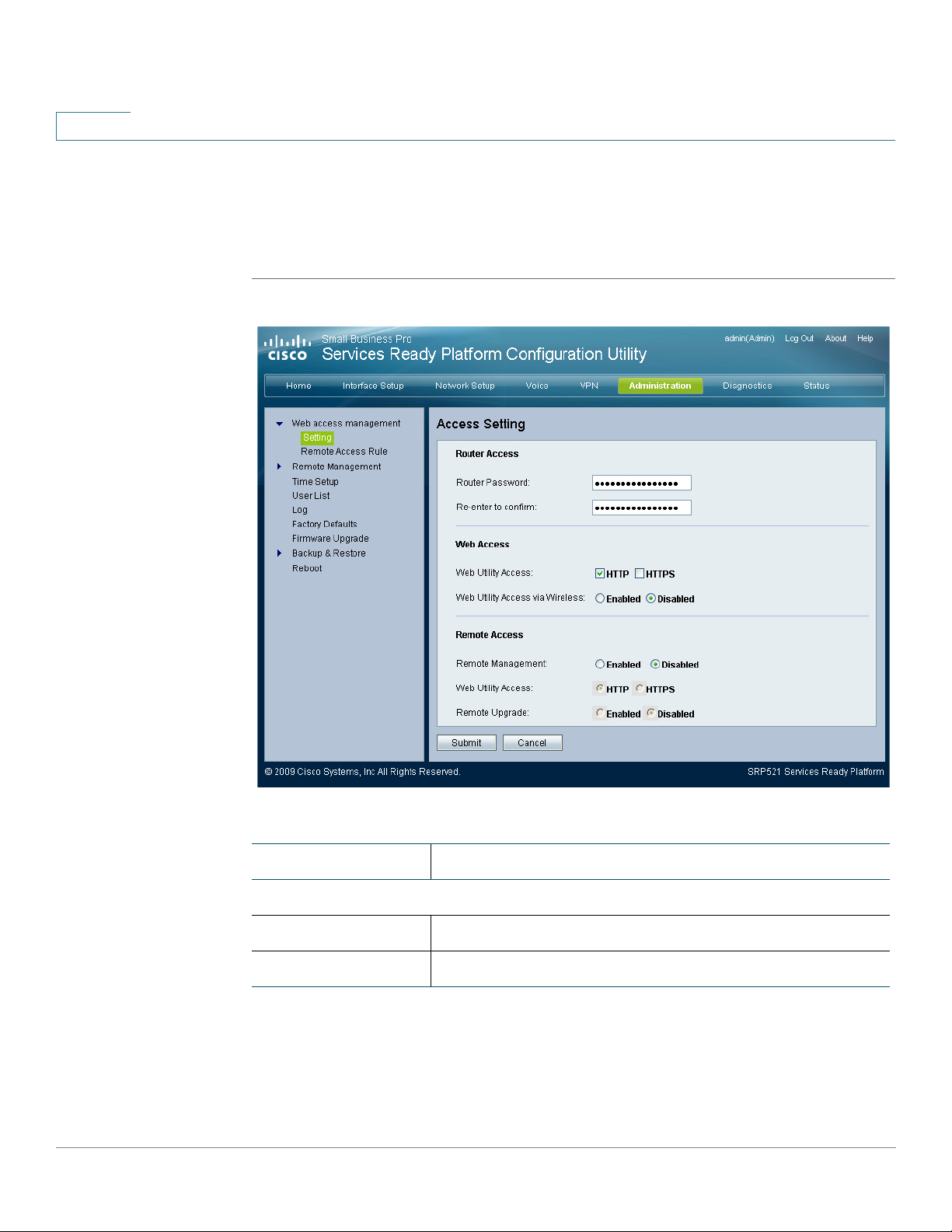
7
Administration Settings
Web Access Management
STEP 4 Select Web Access options.
STEP 5 Select Remote Access options.
STEP 6 Click Submit to save your settings.
Field Description
Router Access
Router Password The new password for the gateway.
Re-enter to confirm The new Password entered a second time to confirm it.
86 SRP 521 VoIP Gateway Administration Guide
Page 87

Administration Settings
Web Access Management
7
REVIEW DRAFT — CISCO CONFIDENTIAL
Field Description
Web Access
Web Utility Access To access this web utility, you can have no security
HTTP or security HTTPS. For HTTPS, enter https://
xxx.xxx.xxx.xxx (the x’s represent the gateway’s Internet
IP address) in your web browser's Address field.
Web Utility Access
via Wireless
Remote Access
Remote
Management
Web Utility Access To access this web utility, you can have no security
Remote Upgrade If enabled, the gateway firmware can be upgraded from
This option specifies whether an administrator can
access the web utility from a wireless station.
This feature allows you to manage your gateway from a
remote location, via the Internet.
(HTTP) or security (HTTPS). For HTTPS, enter https://
xxx.xxx.xxx.xxx (the x’s represent the gateway’s Internet
IP address) in your web browser's Address field.
Internet.
Remote Access Rule
The settings for Remote Access Rule are set on this page. Clicking Add Rule
button opens the Remote Access Rule page.
STEP 1 Click Administration on the tab and then click Web Access Management in the
navigation pane. Click Remote Access Rule. The Remote Access Rule page
appears.
STEP 2 Click Add Rule.
STEP 3 Choose a WAN interface.
STEP 4 Choose a port number that will open the WAN access.
STEP 5 Choose a LAN interface.
STEP 6 Choose a port number that will open the LAN access.
STEP 7 If you want to be able to access the gateway from any external IP address, select
Any IP Address. If you want to specify an external IP address or range of IP
SRP 521 VoIP Gateway Administration Guide 87
Page 88

7
Administration Settings
Web Access Management
addresses, then select the second option and complete the fields provided.
STEP 8 Click Submit to save your settings.
Field Description
WAN The WA N in ter fa c e.
WAN Remote
Management Port
LAN The LAN interface.
LAN Remote
Management Port
Allowed Remote IP
Address
88 SRP 521 VoIP Gateway Administration Guide
The port number that will open the WAN access.
The port number that will open the LAN access.
The allowed remote IP address or range of addresses.
Page 89

Administration Settings
Remote Management
REVIEW DRAFT — CISCO CONFIDENTIAL
Remote Management
TR069
This feature lets you configure communication with an ACS server via TR-069
(CWMP).
STEP 1 Click Administration on the tab and then click Remote Management in the
navigation pane. Click TR-069. The TR-069 page appears.
STEP 2 Click Enabled to enable TR-069.
STEP 3 Enter the URL for ACS. The format should be http(s)://xxx.xxx.xxx.xxx:port or
xxx.xxx.xxx.xxx:port. The xxx.xxx.xxx.xxx is domain name or IP of ACS server;
and after “:” is port. Both IP and port must be filled.
7
STEP 4 Enter the ACS username and password.
STEP 5 Enter the Connection request username and password.
STEP 6 Enter the periodic inform interval.
STEP 7 Click Submit to save your settings.
SRP 521 VoIP Gateway Administration Guide 89
Page 90

7
Administration Settings
Remote Management
Field Description
Status Select an option to enable or disable TR-069.
ACS URL The URL for ACS. The format should be http(s)://
xxx.xxx.xxx.xxx:port or xxx.xxx.xxx.xxx:port. The
xxx.xxx.xxx.xxx is domain name or IP of ACS server;
and after “:” is port. Both IP and port must be filled.
ACS Username The username for ACS. The default username is OUI-
Serial Number; this should be the same as configured at
ACS side and must be filled.
ACS Password The password for ACS. This should be the same as
configured at ACS side and must be filled.
Connection Request
URL
90 SRP 521 VoIP Gateway Administration Guide
This field will be auto-filled and does not need to be
filled manually. The format is http://xxx.xxx.xxx.xxx:port.
The xxx.xxx.xxx.xxx is WAN IP of CPE.
Page 91

Administration Settings
Remote Management
7
REVIEW DRAFT — CISCO CONFIDENTIAL
Field Description
Connection Request
Username
Connection Request
Password
Periodic Inform
Interval
Periodic Inform
Enable
Request Download If applied, ACS may call the Download RPC after it
Connection request username. This should be the same
as configured at ACS side.
Connection request password.This should be the same
as configured at ACS side.
The periodic inform interval. The default value is 86400
seconds.
To enable or disable periodic inform.
receives the request from CPE.
SNMP
SNMP is a popular network monitoring and management protocol.
STEP 1 Click Administration on the tab and then click Remote Management in the
navigation pane. Click SNMP. The SNMP page appears.
STEP 2 Click Enabled to enable SNMP.
STEP 3 Choose a trusted IP setting.
STEP 4 Click Submit to save your settings.
SRP 521 VoIP Gateway Administration Guide 91
Page 92

7
Administration Settings
Remote Management
Field Description
Enable/Disable To enable SNMP identification, click Enabled. To disable
SNMP, click Disabled.
Trusted IP Only trusted IP or IP range can access this gateway via
SNMP.
Get Community Enter the password that allows read-only access to the
SNMP information of the gateway.
Set Community Enter the password that allows read/write access to the
SNMP information of the gateway.
Local TFTP
STEP 1 Click Administration on the tab and then click Remote Management in the
navigation pane. Click Local TFTP. The Local TFTP Control page appears.
STEP 2 Click Enabled to enable TFTP.
STEP 3 Click Submit to save your settings.
92 SRP 521 VoIP Gateway Administration Guide
Page 93

Administration Settings
Time Setup
7
REVIEW DRAFT — CISCO CONFIDENTIAL
Time Setup
STEP 1 Click Administration on the tab and then click Time S e tu p in the navigation pane.
STEP 2 Choose your timezone.
STEP 3 Select Automatically adjust clock for daylight saving changes option if you want
STEP 4 If you want to use the default Network Time Protocol (NTP) server, use the default
Field Description
TFTP Specify whether TFTP is enabled or disabled. The
default is Disabled.
This feature allows you set parameters related to time for the gateway.
The Time Setup page appears.
the gateway to automatically adjust for daylight saving time.
setting, Auto. If you want to specify the NTP server, select Manual, and enter the
URL or IP address of the NTP server you want to use.
STEP 5 The Resync timer controls how often the gateway resyncs with the NTP server.
Enter the number of seconds you want the interval to be.
SRP 521 VoIP Gateway Administration Guide 93
Page 94

7
Administration Settings
Time Setup
STEP 6 Click Submit to save your settings.
Field Description
Time Zone The timezone that the gateway is set to.
Automatically adjust
clock for daylight
saving changes
Time Se r ver
Address
Resync Timer The timer controls how often the gateway resyncs with
Select this option if you want the gateway to
automatically adjust for daylight saving time. This option
is enabled by default.
If you want to use the default Network Time Protocol
(NTP) server, use the default setting, Auto. If you want to
specify the NTP server, select Manual, and enter the
URL or IP address of the NTP server you want to use.
the NTP server. Enter the number of seconds you want
the interval to be. The default is 3600 seconds.
94 SRP 521 VoIP Gateway Administration Guide
Page 95

Administration Settings
User List
User List
STEP 1 Click Administration on the tab and then click User List in the navigation pane. The
STEP 2 Click Add User.
STEP 3 Enter a new Username.
STEP 4 Enter a password.
STEP 5 Re-enter the password to confirm it.
STEP 6 Select administrative power of the new user.
7
REVIEW DRAFT — CISCO CONFIDENTIAL
The settings for User List are set on this page. Clicking the Add Rule button, opens
the User Add page.
User List page appears.
STEP 7 Click Submit to save your settings.
SRP 521 VoIP Gateway Administration Guide 95
Page 96

7
Administration Settings
Log
Field Description
Username The new Username.
Password To ensure the security of the gateway, you will be asked
for your password when you access the Web-based
Utility. The default password is admin.
Confirm password It is recommended that you change the default
password to another one. Enter a new gateway
password and then enter it again in the Re-enter to
Confirm field.
Power Select power of new User. The choices are Admin and
Guest.
Log
The gateway has the ability to record incoming, outgoing, and DHCP logs. The
Incoming Log will display a temporary log of the source IP addresses and
destination port numbers for the incoming Internet traffic. The Outgoing Log will
display a temporary log of the local IP addresses, destination URLs/IP addresses,
and service/port numbers for the outgoing Internet traffic.
STEP 1 Click Administration on the tab and then click Log in the navigation pane. The Log
page appears.
STEP 2 Click Enabled to enable logging.
STEP 3 Choose the log type from the Log List area.
STEP 4 Click Apply to save your settings.
96 SRP 521 VoIP Gateway Administration Guide
Page 97

Administration Settings
Factor y Defaults
7
REVIEW DRAFT — CISCO CONFIDENTIAL
Field Description
Status To access activity logs, select Enabled. With logging
Log List The log type. To specify the log type, select Incoming
Factory Defaults
You can set the gateway to its settings as it was when it was shipped from the
factory.
STEP 1 Click Administration on the tab and then click Factory Defaults in the navigation
pane. The Factory Defaults page appears.
STEP 2 Click Ye s in the Restore Router Factory Defaults to restore the gateway to its
factory defaults.
enabled, you can view temporary logs. Click Disabled to
disable this function.
Log, Outgoing Log, or DHCP Client Log.
STEP 3 Click Ye s in the Restore Voice Factory Defaults to restore the voice settings to
factory defaults.
SRP 521 VoIP Gateway Administration Guide 97
Page 98

7
Administration Settings
Firmware Upgrade
STEP 4 Click Submit to save your settings.
Field Description
Restore Router
Factory Defaults
Restore Voice
Factory Defaults
Firmware Upgrade
You can upgrade the firmware on the gateway.
To reset the gateway settings to the default values,
select Yes. Then click Submit. Any custom gateway
settings you have saved will be lost when the default
settings are restored.
To reset the voice settings to the default values, select
Yes. Then click Submit. Any custom Voice settings you
have saved will be lost when the default settings are
restored.
98 SRP 521 VoIP Gateway Administration Guide
Page 99
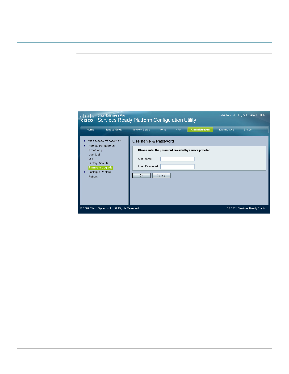
Administration Settings
Backup & Restore
STEP 1 Click Administration on the tab and then click Firmware Upgrade in the navigation
STEP 2 Enter the username and password provided by your service provider.
STEP 3 Click OK to upgrade the gateway.
7
REVIEW DRAFT — CISCO CONFIDENTIAL
pane. The Username & Password page appears.
Field Description
Username Username provided by the service provider.
User Password Password provided by the service provider.
Backup & Restore
Backup Configuration
The Backup Configuration feature lets you to backup the configuration settings of
the gateway to a file which you can use later to restore the gateway to the same
settings.
SRP 521 VoIP Gateway Administration Guide 99
Page 100

7
Administration Settings
Backup & Restore
STEP 1 Click Administration on the tab and then click Backup & Restore in the navigation
pane. Click Backup Configuration. The Backup Configuration page appears.
STEP 2 Click Backup to save the configuration of the gateway.
Field Description
Backup To back up configuration settings of the gateway, click
Backup and follow the on screen instructions.
Restore Configuration
The Restore Configuration feature lets you restore the gateway to configuration
settings from a previous backup session.
STEP 1 Click Administration on the tab and then click Backup & Restore in the navigation
pane. Click Restore Configuration. The Restore Configuration page appears.
STEP 2 Click Browse and select previously backed up configuration file.
STEP 3 Click Restore to restore the configuration of the gateway.
100 SRP 521 VoIP Gateway Administration Guide
 Loading...