

Page 1
Cisco Small Business Pro
SPA9000 Voice System Version 6.1
SPA9000 Voice System, SPA400 Internet Telephony
Gateway with 4 FXO ports and SPA9XX IP Phones
ADMINISTRATION
GUIDE
Page 2

CCDE, CCSI, CCENT, Cisco Eos, Cisco HealthPresence, the Cisco logo, Cisco Lumin, Cisco Nexus, Cisco Nurse Connect, Cisco Stackpower, Cisco StadiumVision,
Cisco TelePresence, Cisco WebEx, DCE, and Welcome to the Human Network are trademarks; Changing the Way We Work, Live, Play, and Learn and Cisco Store are service marks;
and Access Registrar, Aironet, AsyncOS, Bringing the Meeting To You, Catalyst, CCDA, CCDP, CCIE, CCIP, CCNA, CCNP, CCSP, CCVP, Cisco, the Cisco Certified Internetwork
Expert logo, Cisco I OS, Ci sco Press, Cisco Systems, Cisco Systems Capital, the Cisco Systems logo, Cisco Unity, Collaboration Without Limitation, EtherFast, EtherSwitch, Event
Center, Fast Step, Follow Me Browsi ng, FormShare, GigaDrive, HomeLink, Internet Quotient, IOS, iPhon e, iQuick Study, IronPort, the IronPort logo, LightStream, Linksys,
MediaTone, MeetingPlace, MeetingPlace Chime Sound, MGX, Networkers, Networking Academy, Network Registrar, PCNow, PIX, PowerPanels, ProConnect, ScriptShare,
SenderBase, SMARTnet, Spectrum Expert, StackWise, The Fastest Way to Increase Your Internet Quotient, TransPath, WebEx, and the WebEx logo are registered trademarks of
Cisco Systems, Inc. and/or its affiliates in the United States and certain other countries.
All other trademarks mentioned in this document or website are the property of their respective owners. The use of the word partner does not imply a partn er ship r el at ion ship betw een
Cisco and any other company. (0903R)
© 2009 Cisco Systems, Inc. All rights reserved. OL-17899-02
Page 3

About This Document ix
Contents
Purpose ix
Audience ix
Firmware x
Organization xi
Document Conventions xii
Finding Information in PDF Files xiii
Chapter 1: Getting Started 16
Introduction to the SPA9000 Voice System 16
SPA9000 IP PBX 17
SPA400 SIP-PSTN Gateway and Voicemail Server 18
IP Phones and Accessories 18
Deployment Scenarios 18
PSTN Access and Local Voice Mail 19
ITSP Service Only 20
ITSP Service, PSTN Access and Local Voice Mail 21
ITSP Service, PSTN and ISDN Access and Local Voice Mail 22
Initial Installation, and Configuration 23
Chapter 2: Basic Administration of the SPA9000 24
Upgrading Firmware for the SPA9000 25
Connecting to the SPA9000 Administration Web Server 27
Saving or Discarding Changes SPA9000 27
Access Levels 28
Setting Passwords for User and Administrator Accounts 29
SPA9000 Voice System Administration Guide i
Page 4

Contents
Configuring Basic Settings 29
Setting Up the WAN Connection for the SPA9000 30
Setting the Date and Time 30
Configuring Daylight Saving Time 31
SPA9000 Ethernet Port 33
LAN and Application Guidelines 33
Configuring Multicast Addressing and Group Paging 33
Collecting System Logs and Debug Information 36
Viewing Information about the SPA9000 39
Viewing Information about Client Stations 39
Using the Interactive Voice Response Unit 40
Using the IVR Menu 40
Entering a Password through the IVR 45
Chapter 3: Configuring Your System for ITSP Interoperability 47
About the SPA9000 Voice System and SIP 47
Network Address Translation (NAT) and Voice over IP (VoIP) 49
NAT Mapping with Session Border Controller 49
NAT Mapping with SIP-ALG Router 49
Configuring NAT Mapping with a Static IP Address 49
Configuring NAT Mapping with STUN 51
Determining the Router's NAT Mechanism 53
Firewalls and SIP 54
Configuring SIP Timer Values 55
Chapter 4: Configuring Phone Lines and Calling Routing Behavior 56
Configuring SPA9000 FXS Ports 57
SPA9000 Voice System Administration Guide ii
Page 5

Contents
Configuring Line Interfaces on the SPA9000 58
Configuring a Line Interface for ITSP Service 58
Configuring a Line Interface for a SPA400 (PSTN or Voice Mail) 60
Configuring Call Capacity for a Line Interface 63
Configuring Dial Plans 66
About Dial Plans 66
Editing Dial Plans 74
Managing the Line Selection for Outbound Calls 78
Line Availability 78
Configuring a Call Routing Rule 79
Entering a Call Routing Rule 81
Managing Caller ID Settings for Outgoing Calls 82
Call Forwarding Support on SPA9000 82
Call Transfer Support on SPA9000 84
Call Forward Bridge Mode 84
Call Transfer Bridge Mode 84
Managing Inbound Calls with the Contact List 85
Routing an Inbound Call to the Auto Attendant 85
Routing an Inbound Call to a Receptionist or Client Stations 85
Example Contact List Rules 86
Supporting Multiple DID Numbers Per Line Interface 87
Supporting Direct Inward Dialing to Phone Extensions 88
Entering a Contact List Rule 91
Managing Inbound Calls with Hunt Groups 92
Syntax for Hunt Rules 93
Examples for Hunt Rules 94
Managing Inbound Calls with Shared Line Appearances 98
SPA9000 Voice System Administration Guide iii
Creating a Hunt Rule 96
Page 6

About Shared Line Appearances 98
Chapter 5: Administering the SPA400 and Voice Mail Service 102
Connecting to the SPA400 Administration Web Server 103
Configuring the SPA400 Network Connection 104
Saving or Discarding Changes on the SPA400 105
Managing Access to the SPA400 Configuration Utility 106
Upgrading the Firmware for the SPA400 107
Configuring a SPA400 to Interoperate with the SPA9000 108
Configuring a SPA400 for PSTN Access 111
Contents
Configuring a SPA400 for Voice Mail Service 112
Voice Mail Capacity 112
Configuring Local Voice Mail Service on a SPA400 113
Setting Up Voice Mail on Each Station 116
Enabling Remote Voice Mail Access (Optional) 119
Managing the Voice Mail Messages on the USB Key 121
Enabling Debugging on the SPA400 122
Chapter 6: Configuring Music on Hold 125
Using the Internal Music Source for Music On Hold 125
Using the Internal Music Source 125
Changing the Music File for the Internal Music Source 126
Configuring a Streaming Audio Server 127
About the Streaming Audio Server 127
SPA9000 Voice System Administration Guide iv
Configuring the Streaming Audio Server 129
Using the IVR with an SAS Line 130
Page 7

Chapter 7: Configuring the Auto Attendant 131
How the Auto Attendant Works 131
Working with the Auto Attendant Greetings 133
Using Pre-Recorded Prompts 133
Recording an Auto Attendant Prompt 134
Downloading Prompts 137
Writing an Auto Attendant Script 138
An Introduction to XML Scripting Grammar in AA Script Examples 138
Elements of XML Scripting Grammar 142
Auto Attendant XML Instructions Set 145
Entering an Auto Attendant Script 147
Contents
Configuring the DayTime, NightTime and Weekend/Holiday Auto
Attendants 148
Configuring Dial Plans for the Auto Attendant 150
Chapter 8: Localization 151
Localizing the SPA9000 Auto Attendant Prompts 151
Local Time Configuration 154
Configuring the SPA9000 and SPA9xx Call Progress Tones 154
Localizing the SPA400 Voice Mail Prompts 160
Localizing the SPA400 Call Disconnect Tones 161
Localizing the SPA400 Caller ID Method 163
Appendix A: Advanced Topics in SPA9000 Administration 165
Technology Background 165
SPA9000 Voice System Administration Guide v
Session Initiation Protocol 166
SPA9000 Media Proxy 167
Page 8

Contents
Using the SPA9000 with a Firewall or Router 168
SPA400 SIP-PSTN Gateway 169
SPA9000 Architecture 170
SIP-NAT Interoperation 172
Advanced Call Control and Routing 173
Configuring Vertical (Supplementary) Service Codes 173
Managing the Outbound Call Routing Groups 175
Configuring Outbound Call Codec Selection Codes 177
Advanced Topics for SPA400 Voice Mail Service 178
How Voicemail Works 179
Checking Voicemail from an External Number 180
Depositing Voicemail 180
Subscribing to Voicemail Notification 182
Remote Provisioning Features 183
Using Configuration Profiles 183
Client Auto-Configuration 184
Manual Client Configuration 185
Client Registration 188
Using the Upgrade URL 189
Using the Resync URL 190
Using the Reboot URL 190
Appendix B: SPA9000 Field Reference 191
Router Tab 191
Status page 191
Wan Setup page 193
Voice tab 197
SPA9000 Voice System Administration Guide vi
Lan Setup page and Application page 196
Info page 197
Page 9

System page 200
SIP Page 202
Provisioning page 224
Regional page 224
FXS 1/2 page 241
Line 1/2/3/4 page 251
Appendix C: SPA400 Field Reference 261
Setup 261
Basic Setup 262
SPA9000 Interface 262
Voice 264
Voicemail Server 268
Contents
Voicemail Users 269
Administration 270
Management 270
Factory Default 270
USB Setting 271
Firmware Upgrade 271
Reboot 271
Status 272
Gateway 272
Event Logs 273
Set Log Level 273
Tone 274
Appendix D: Where to Go From Here 275
Product Resources 275
Related Documentation 276
SPA9000 Voice System Administration Guide vii
Page 10

Appendix E: Glossary 278
Appendix F: Acronyms 281
Contents
SPA9000 Voice System Administration Guide viii
Page 11

About This Document
The SPA9000 Voice System Administration Guide is intended to help VARs and
Service Providers to manage and configure the SPA9000 Voice System. This
preface provides helpful information about this guide and other resources that are
available to you. Before you begin to use this guide, refer to the following topics:
• “Purpose,” on page ix
• “Audience,” on page ix
• “Firmware,” on page x
• “Organization,” on page xi
Preface
Purpose
Audience
• “Document Conventions,” on page xii
• “Finding Information in PDF Files,” on page xiii
This document provides information that an administrator needs to configure the
SPA9000 Voice System, which typically consists of a SPA9000 IP PBX, one or
more SPA900 Series IP phones, and the optional SPA400 PSTN gateway and
voice mail server. This guide focuses primarily on the tasks that an administrator
performs to configure a SPA9000 with the SPA9000 administration web server.
NOTE This guide does not cover initial installation and configuration, SPA900 Series
phone configuration, the Setup Wizard, or provisioning. See “Related
Documentation” in Appendix D, on page 276.
This document is written for the following audience:
• Service providers offering services using Cisco SPA products
• VARs and resellers who need configuration references for Cisco SPA products
SPA9000 Voice System Administration Guide ix
Page 12
Firmware
Preface
• System administrators or anyone who installs and administers the SPA9000
Voice System
NOTE This guide does not provide the configuration information required by specific
service providers. Please consult with the service provider for specific service
parameters.
This guide describes the features that are available in the following firmware
releases (and higher versions). You can find all available firmware updates by
going to Cisco.com and choosing Support. Or visit the following URL and enter the
model number in the Software Search box:
http://tools.cisco.com/support/downloads
Product Firmware Version
SPA9000 6.1.5
SPA400 1.1.2.2
SPA901 5.1.5
SPA921/SPA941 5.1.8
SPA922/942 6.1.3
SPA962 6.1.3
WIP310 5.0.8
SPA9000 Voice System Administration Guide x
Page 13

Organization
Preface
The information in this guide is organized into the following chapters and
appendices:
Chapter Description
Chapter 1, “Getting
Started.”
Chapter 2, “Basic
Administration of the
SPA9000.”
Chapter 3, “Configuring
You r S ys tem fo r I TS P
Interoperability”
Chapter 4, “Configuring
Phone Lines and Calling
Routing Behavior”
Chapter 5, “Administering
the SPA400 and Voice Mail
Service”
Chapter 6, “Configuring
Music on Hold”
This chapter introduces you to the SPA9000
Voice System by describing the components and
presenting several deployment scenarios.
This chapter introduces you to basic
administrative tasks using the SPA9000
administration web server and the Interactive
Voice Response Unit.
This chapter provides configuration details to help
you to ensure that your infrastructure properly
supports voice services.
This chapter describes many features that you
can configure on the SPA9000 to ensure smooth
handling of all inbound and outbound calls, and
ease of use.
This chapter guides you through the process of
configuring and managing the SPA400 for PSTN
access and voice mail service.
This chapter explains how to configure Music on
Hold using either a music file or streaming audio.
Chapter 7, “Configuring the
Auto Attendant”
Chapter 8, “Localization” This chapter explains how to localize your
Appendix A, “Advanced
Topics in SPA9000
Administration”
SPA9000 Voice System Administration Guide xi
This chapter describes how to configure the
SPA9000 Voice System Auto Attendant (AA) by
using the IVR and XML scripting.
SPA9000 Voice System with the language files,
tones, and ring patterns for your region.
This appendix provides more detailed technical
information for administrators who want to
understand how the SPA9000 Voice System
works.
Page 14

Chapter Description
Preface
Appendix B, “SPA9000
Field Reference”
Appendix C, “SPA400 Field
Reference”
Appendix D, “Where to Go
From Here”
Appendix E, “Glossary”
Appendix F, “Acronyms”
Document Conventions
The following table describes the typographic conventions that are used in this
document.
Typographic
Element
This appendix describes the fields on each page
of the SPA9000 administration web server.
This appendix describes the fields on each page
of the SPA400 administration web server.
This appendix describes additional resources
that are available to help you and your customer
obtain the full benefits of the SPA9000 Voice
System.
These resources help you to understand the
terms and acronyms that are used in this guide.
Meaning
Boldface
Italic
Monospaced
Font
May indicate either of the following:
• A user interface element that you need to click, select, or
otherwise act on
• A literal value to be entered in a field.
May indicate either of the following:
• A variable that should be replaced with a literal value.
• The name of a page, section, or field in the user interface
Indicates code samples or system output.
SPA9000 Voice System Administration Guide xii
Page 15

Finding Information in PDF Files
The SPA9000 Voice System documents are published as PDF files. The PDF Find/
Search tool within Adobe® Reader® lets you find information quickly and easily
online. You can perform the following tasks:
• Search an individual PDF file.
• Search multiple PDF files at once (for example, all PDFs in a specific folder or
disk drive).
• Perform advanced searches.
Finding Text in a PDF
Follow this procedure to find text in a PDF file.
STEP 1 Enter your search terms in the Find text box on the toolbar.
Preface
NOTE By default, the Find tool is available at the right end of the Acrobat toolbar. If
the Find tool does not appear, choose Edit > Find.
STEP 2 Optionally, click the arrow next to the Find text box to refine your search by
choosing special options such as Whole Words Only.
STEP 3 Press Enter.
STEP 4 Acrobat displays the first instance of the search term.
STEP 5 Press Enter again to continue to more instances of the term.
SPA9000 Voice System Administration Guide xiii
Page 16
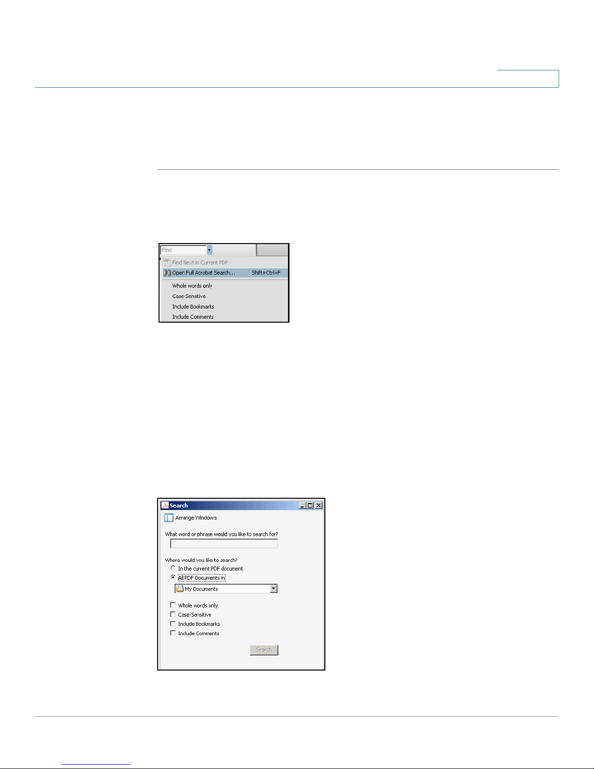
Finding Text in Multiple PDF Files
The
Search
on your PC or local network. The PDF files do not need to be open.
STEP 1 Start Acrobat Professional or Adobe Reader.
window lets you search for terms in multiple PDF files that are stored
Preface
STEP 2 Choose Edit > Search, or click the arrow next to the
Open Full Acrobat Search.
STEP 3 In the
a. Enter the text that you want to find.
b. Choose All PDF Documents in.
c. If you want to specify additional search criteria, click Use Advanced Search
d. Click Search.
Search
From the drop-down box, choose Browse for Location. Then choose the
location on your computer or local network, and click OK.
Options, and choose the options you want.
window, complete the following steps:
Find
box and then choose
SPA9000 Voice System Administration Guide xiv
Page 17
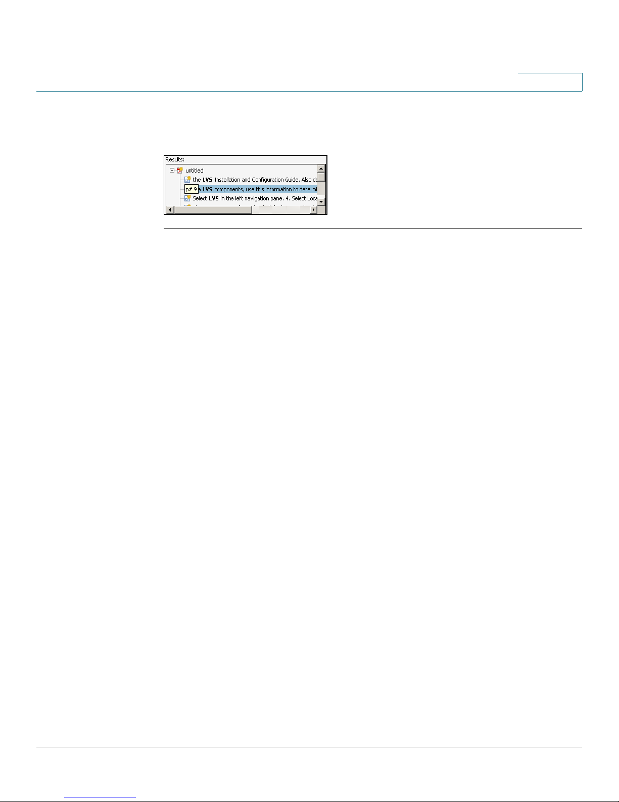
Preface
STEP 4 When the Results appear, click + to open a folder, and then click any link to open
the file where the search terms appear.
For more information about the Find and Search functions, see the Adobe Acrobat
online help.
SPA9000 Voice System Administration Guide xv
Page 18

Getting Started
This chapter introduces you to the SPA9000 Voice System by describing the
components and presenting several deployment scenarios.
NOTE This chapter is essential reading before you begin installing the equipment or
configuring the system.
1
• “Introduction to the SPA9000 Voice System,” on page16
• “Deployment Scenarios,” on page18
• “Initial Installation, and Configuration,” on page 23
Introduction to the SPA9000 Voice System
The SPA9000 Voice System is an affordable and feature-rich IP telephone system
that is designed especially for the Small and Home Office. The SPA9000 Voice
System uses standard TCP/IP protocols and can provide global connectivity
through any Internet Telephony Service Provider (ITSP) that supports the Session
Initiation Protocol (SIP).
At minimum, the SPA9000 Voice System includes a SPA9000 IP PBX and one or
more SPA900 series IP phones. These devices are connected through a switch to
a local area network. With an Internet connection, the SPA9000 Voice System can
subscribe to ITSP services to take advantage of low calling rates. With the
SPA400, the SPA9000 Voice System can connect to the Public Switched
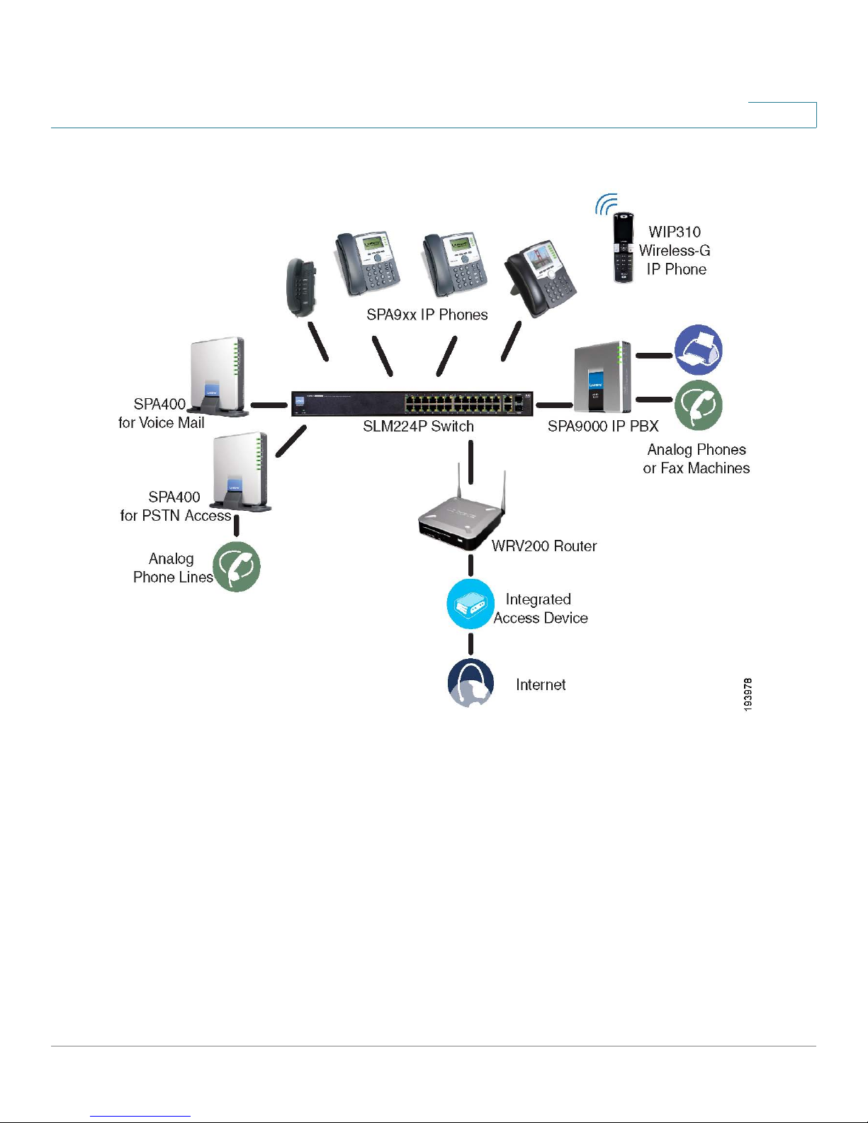
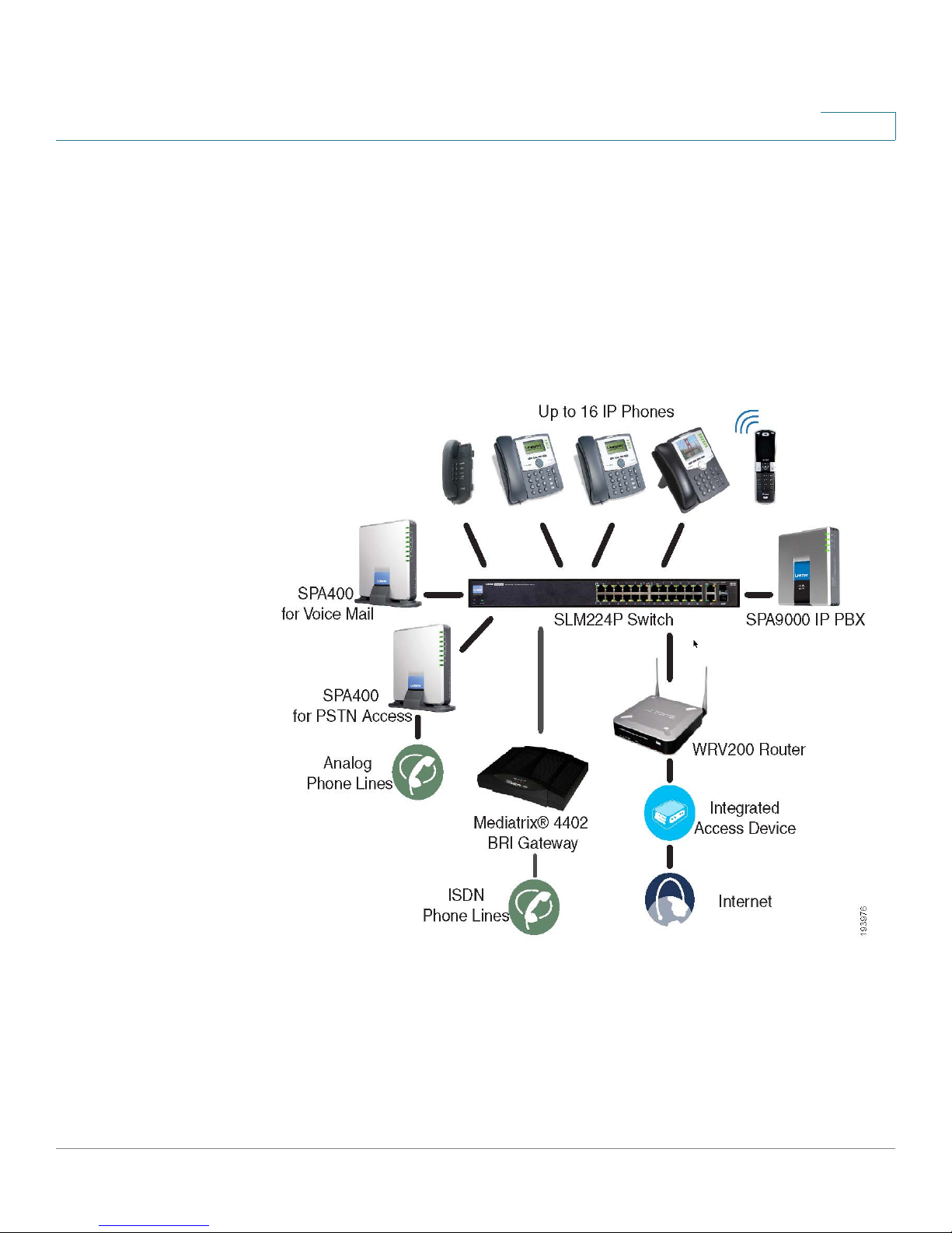
Telephone Network (PSTN) to support analog phone lines. See Figure 1 “SPA9000
Voice System with the SPA9000 and SPA400” on page17 to learn more about a
typical deployment.
SPA9000 Voice System Administration Guide 16
Page 19
Getting Started
Introduction to the SPA9000 Voice System
Figure1 SPA9000 Voice System with the SPA9000 and SPA400
1
SPA9000 IP PBX
The SPA9000 is an IP PBX that supports up to 16 phones. It also has a built-in
Analog Telephone Adapter (ATA) with two FXS ports for analog telephones, fax
devices, or an external music source for the music on-hold service. Devices
connected to the FXS ports are not included in the device count.
The SPA9000 has four line interfaces, which can be configured in any combination
for ITSP service, ISDN access, SPA400 PSTN access, or SPA400 voice mail
service. A different ITSP account can be configured on each line interface. If a
service provider supplies a group of sequential direct inward dial (DID) phone
numbers (such as 408-555-0100 through 555-0145) the SPA9000 can support all
of the assigned numbers on a single line interface.
SPA9000 Voice System Administration Guide 17
Page 20
Getting Started
Deployment Scenarios
1
The SPA9000 includes an Auto Attendant service that plays pre-recorded voice
messages to offer the caller a menu of choices and to direct the call. When the
Auto-Attendant is enabled, it parses and operates on user key presses according
to the rules that are specified in the Auto Attendant script.
SPA400 SIP-PSTN Gateway and Voicemail Server
The SPA400 provides a SIP-PSTN gateway for voice connectivity between the
PSTN and the local client stations that are connected to the SPA9000. It also
includes an integrated voice mail application that supports up to 32 voice mail
accounts with customized greetings, providing the ability to receive and playback
voice mail messages.
Each SPA400 occupies one of the four line interfaces on the SPA9000. The
SPA400 has four ports for that can be connected to PSTN or ISDN lines.
IP Phones and Accessories
The SPA9000 Voice System supports any of the Cisco SPA900 Series SIP IP
Phones, as well as the Cisco WIP310 Wireless IP Phone.
NOTE This guide explains how to configure the SPA9000 and the SPA400 to support the
calling features on the phones. For more information about the phones, see the
SPA9x2 Phone Administration Guide, the SPA9x2 Phone User Guide, and the
Cisco Wireless-G IP Phone User Guide.
Deployment Scenarios
The SPA9000 Voice System can meet the calling needs of many small businesses.
Various deployment scenarios are possible. This section includes the following
examples:
• “PSTN Access and Local Voice Mail,” on page19
• “ITSP Service Only,” on page 20
• “ITSP Service, PSTN Access and Local Voice Mail,” on page 21
• “ITSP Service, PSTN and ISDN Access and Local Voice Mail,” on page 22
SPA9000 Voice System Administration Guide 18
Page 21

Getting Started
Deployment Scenarios
1
PSTN Access and Local Voice Mail
In this scenario, the customer requires a robust phone system but is not using VoIP
services. The SPA9000 Voice System is deployed with a SPA9000 IP PBX, one
SPA400 for PSTN access with four FXO ports, and another SPA400 for local voice
mail service. Up to 16 IP phones can be installed. Optionally, analog phones or fax
machines (not illustrated) can be connected to the two phone ports on the
SPA9000.
SPA9000 Voice System Administration Guide 19
Page 22
Getting Started
Deployment Scenarios
1
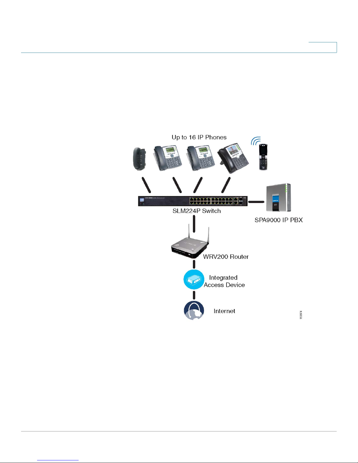
ITSP Service Only
In this scenario, a customer has no legacy telephone numbers and either needs no
voice mail at all or has voice mail hosted by the ITSP. The SPA9000 Voice System
is deployed with the SPA9000 IP PB and VoIP service. Up to 16 IP phones can be
installed. Optionally, analog phones or fax machines (not illustrated) can be
connected to the two phone ports on the SPA9000.
SPA9000 Voice System Administration Guide 20
Page 23
Getting Started
Deployment Scenarios
1
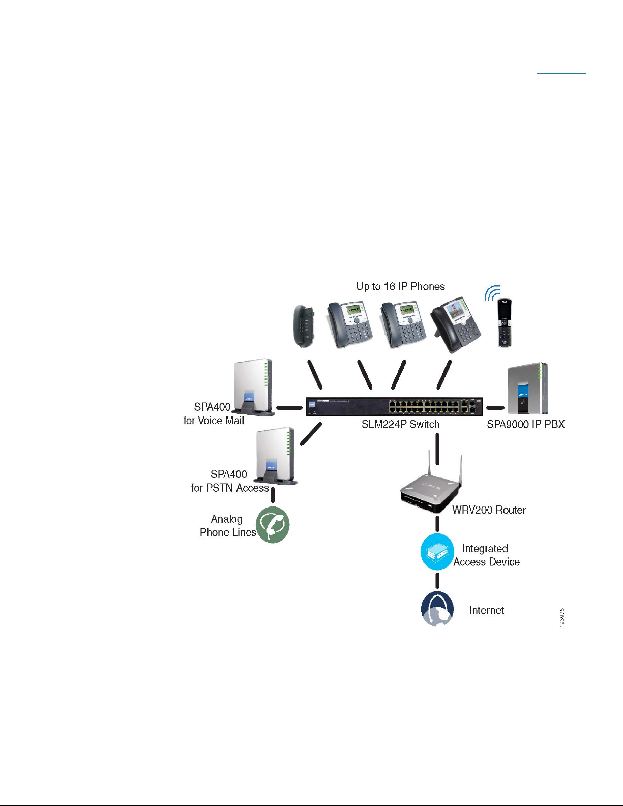
ITSP Service, PSTN Access and Local Voice Mail
In this scenario, the customer wants to use ITSP service for reduced long distance
fees but needs to support legacy local telephone numbers (for example, to receive
calls to a legacy telephone number or to place outbound calls in the local area).
This customer also prefers local voice mail service. The SPA9000 Voice System is
deployed with the SPA9000 IP PBX, VoIP service, one SPA400 unit for voice mail
service, and another SPA400 unit for PSTN access with four FXO ports. Up to 16 IP
phones can be installed. Optionally, analog phones or fax machines (not illustrated)
can be connected to the two phone ports on the SPA9000.
SPA9000 Voice System Administration Guide 21
Page 24
Getting Started
Deployment Scenarios
1
ITSP Service, PSTN and ISDN Access and Local Voice Mail
In this scenario, the customer takes full advantage of the SPA9000 Voice System
solution. This customer has the SPA9000 IP PBX, VoIP service, one SPA400 unit for
voice mail service, and another SPA400 for PSTN access with four FXO ports. In
addition, this installation includes an ISDN Gateway for ISDN BRI access with four
BRI ports. Up to 16 IP phones can be installed. Optionally, analog phones or fax
machines (not illustrated) can be connected to the two phone ports on the
SPA9000.
SPA9000 Voice System Administration Guide 22
Page 25

Getting Started
Initial Installation, and Configuration
Initial Installation, and Configuration
Cisco strongly recommends that you use the SPA9000 Voice System Installation
and Configuration Guide to design your system, to prepare the site, to connect
and configure your equipment, and to set up the essential calling features. By
following the instructions in the installation guide, you can get your system running
in less time and with the settings that help to ensure strong performance.
After you complete the procedures in the installation guide, the users can make
and receive calls. When the optional SPA400 is installed, the users also can record
and retrieve voice mail messages. The SPA9000 has a fully functional Auto
Attendant to greet callers, and a default dial plan that is suitable for most dialing
scenarios. You can use this administration guide to refine the settings, to configure
advanced features, and to manage the system.
1
NOTE Because the SPA9000 Voice System Installation and Configuration Guide
provides all of the procedures that you need for initial installation and configuration,
those instructions are not duplicated in this administration guide.
SPA9000 Voice System Administration Guide 23
Page 26

Basic Administration of the SPA9000
This chapter introduces you to basic administrative tasks using the SPA9000
administration web server and the Interactive Voice Response Unit.
NOTE This administration guide does not cover the initial installation and configuration of
the system. For information about connecting the equipment to start using your
system, see the SPA9000 Voice System Installation and Configuration Guide.
2
See the following topics:
• “Upgrading Firmware for the SPA9000,” on page 25
• “Connecting to the SPA9000 Administration Web Server,” on page 27
• “Saving or Discarding Changes SPA9000,” on page 27
• “Access Levels,” on page 28
• “Setting Passwords for User and Administrator Accounts,” on page 29
• “Configuring Basic Settings,” on page 29
• “Viewing Information about the SPA9000,” on page 39
• “Viewing Information about Client Stations,” on page 39
• “Configuring Multicast Addressing and Group Paging,” on page 33
• “Using the Interactive Voice Response Unit,” on page 40
SPA9000 Voice System Administration Guide 24
Page 27
Basic Administration of the SPA9000
Upgrading Firmware for the SPA9000
Upgrading Firmware for the SPA9000
As needed, you can download new firmware and then install it on the SPA9000.
STEP 1 Download the latest SPA9000 firmware from the following URL:
http://tools.cisco.com/support/downloads/go/Redirect.x?mdfid=282414116
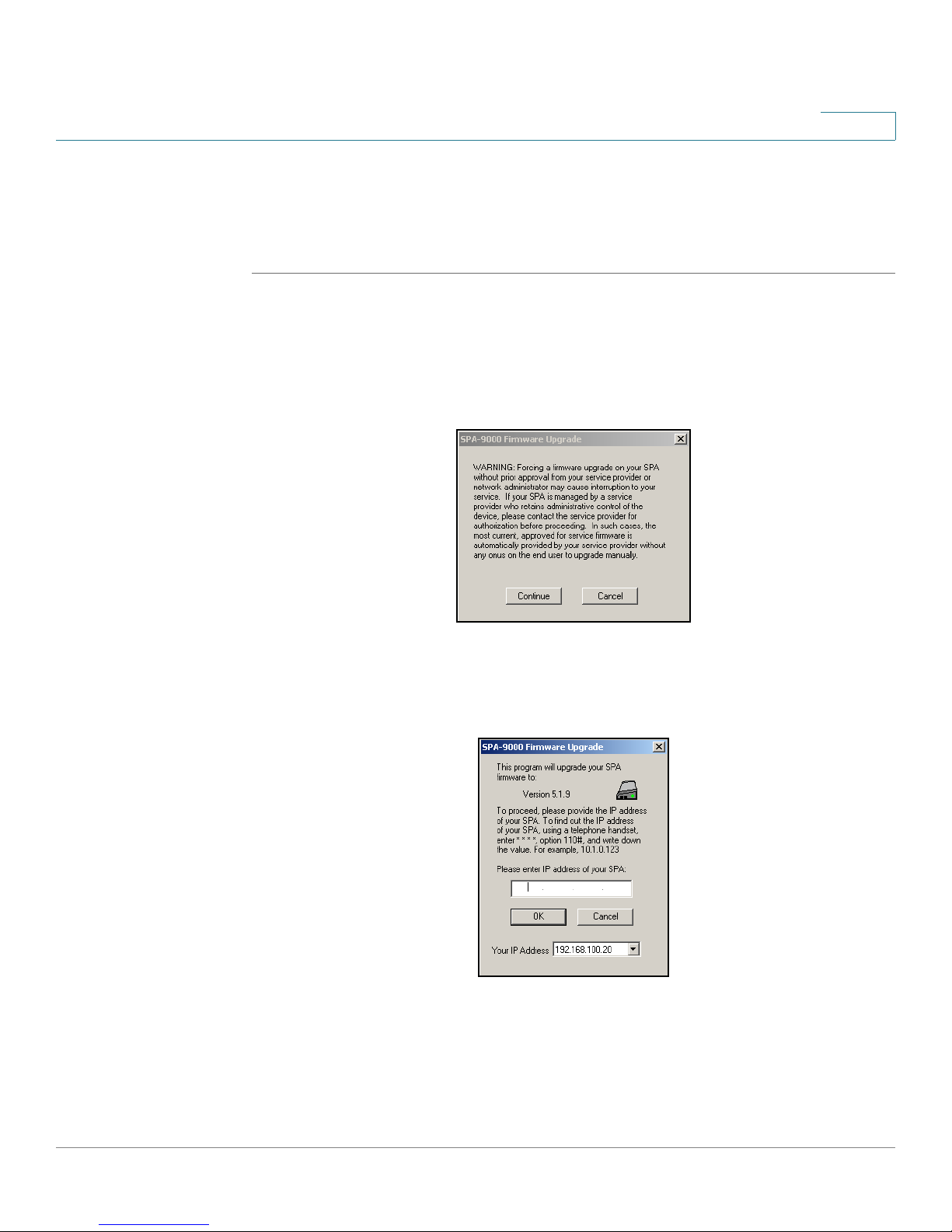
STEP 2 Extract the Zip file, and then run the executable file to upgrade the firmware. When
the
Firmware Upgrade Warning
window appears, click Continue.
2
STEP 3 In the next window that appears, enter the IP address of the SPA9000, and then
click OK.
SPA9000 Voice System Administration Guide 25
Page 28
Basic Administration of the SPA9000
Upgrading Firmware for the SPA9000
2
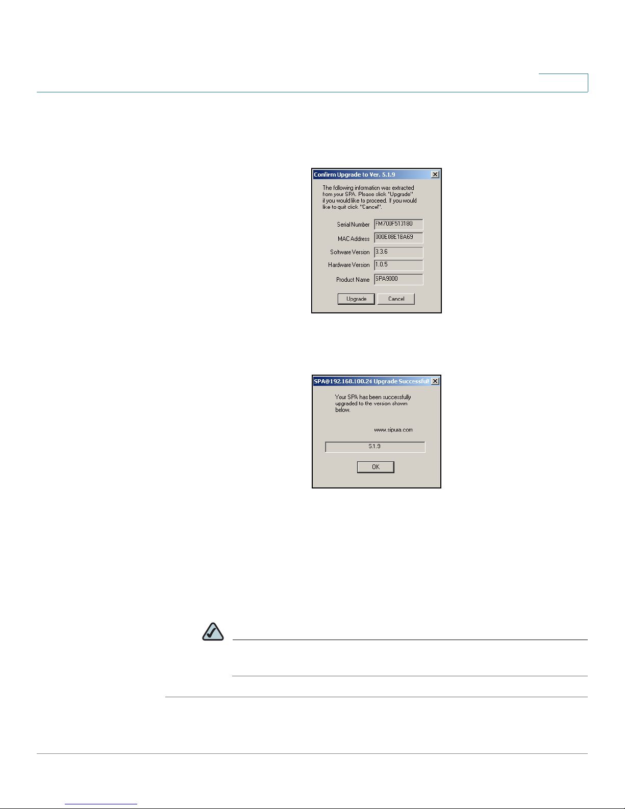
STEP 4 In the
product number appear. Then click Upgrade.
STEP 5 When the confirmation message appears, click OK.
Confirm Upgrade
window, verify that the correct device information and
STEP 6 To verify the upgrade, complete the following steps:
a. Connect to the SPA9000 administration web server, and choose Admin access
with Advanced settings. (See “Connecting to the SPA9000 Administration Web
Server,” on page 27).
b. Review the
firmware version that you installed.
NOTE You may need to refresh your browser to display the updated page
SPA9000 Voice System Administration Guide 26
Router > Status
reflecting the new version number.
page. The
Software Version
field should show the
Page 29
Basic Administration of the SPA9000
Connecting to the SPA9000 Administration Web Server
Connecting to the SPA9000 Administration Web Server
To connect to the administration web server, perform the following steps.
NOTE You should have previously connected and configured the SPA9000 as described
in the SPA9000 Voice System Installation Guide.
STEP 1 Start Internet Explorer on a computer that is on the same network as the SPA9000.
STEP 2 Enter the IP address of the SPA9000.
2
NOTE To find the IP address of the SPA9000, connect an analog telephone to the
Phone 1 or Phone 2 port on the
and press **** on the keypad to access the IVR menu. Press 110# to hear the
IP address.
STEP 3 To view administrative features, click Admin Login and then click Advanced. By
default, no password is required. For more information, see “Setting Passwords for
User and Administrator Accounts,” on page 29.
ALTERNATIVELY: After starting Internet Explorer, enter: <SPA9000_ipaddress>/
admin/advanced
SPA9000. Then lift the receiver of the phone
Saving or Discarding Changes SPA9000
Changes can be saved or discarded at any time.
• Changes are submitted only when you click the Submit All Changes button at
the bottom of a page. When changes are saved, the
depending on the type of changes.
SPA9000 may reboot,
• To discard unsubmitted changes, click the Undo All Changes button at the
bottom of the page.
SPA9000 Voice System Administration Guide 27
Page 30

Basic Administration of the SPA9000
Access Levels
• Unsubmitted changes are retained when you move among the pages within
the Voice module or the Router module. This feature allows you to make
changes on various pages within a module before clicking Submit All
Changes.
• Unsubmitted changes are discarded when you switch between the Router and
Voice tabs, between the User and Administrator accounts, or between the
Basic and Advanced views.
Before you make changes, it is recommended that you save a copy of your current
working configuration:
STEP 1 In Internet Explorer, connect to the administration web server.
STEP 2 From the menu, choose File > Save As.
STEP 3 Save the configuration as Web Page Complete. You can use the saved file to
review the saved settings in all pages of the administrative GUI.
2
Access Levels
NOTE To save a Telephone Configuration, first enter the IP address for the
configuration, and then follow the above procedure.
You can use the SPA9000 administration web server to configure and manage
your system. Three levels of access are available:
• User Level: The User account only has the privilege to access part of the web
profile parameters.
• Administrator Level: The Administrator account has the privilege to modify all
the web profile parameters and can also modify the passwords of both
Administrator and User account.
• Advanced: Administrators and Users can view advanced features by clicking
the Advanced link in the top right corner or lower left corner of the menu bar.
By default, no passwords are assigned for either the Administrator account or the
User account. If the password has been set for the Administrator account, the
browser prompts for authentication.
SPA9000 Voice System Administration Guide 28
Page 31

Basic Administration of the SPA9000
Setting Passwords for User and Administrator Accounts
You can switch from User access to Administrator access by clicking the Admin
Login link. Likewise, you can switch from Administrator access to User access by
clicking the User Login link. If a password is set, you will be prompted to enter the
password after you click the link.
Setting Passwords for User and Administrator Accounts
The Administrator account name for the SPA9000 is admin and the User account
name is user. These account names are case sensitive and cannot be changed.
NOTE The system prompts for an Administrator account password only if a password has
been set. By default, there is no password. You should set a password to protect
your SPA9000 from unauthorized access.
2
STEP 1 Connect to the SPA9000 administration web server, and choose Admin access
with Advanced settings. (See “Connecting to the SPA9000 Administration Web
Server,” on page 27.)
STEP 2 Click Voice tab > System.
STEP 3 In the System Configuration section, enter the Admin Password and the User
Password, as needed. Up to 39 characters are allowed for the passwords.
STEP 4 Click Submit All Changes.
Configuring Basic Settings
This section provides information about the following tasks:
• “Setting Up the WAN Connection for the SPA9000,” on page 30
• “Setting the Date and Time,” on page 30
• “Configuring Daylight Saving Time,” on page 31
• “LAN and Application Guidelines,” on page 33
SPA9000 Voice System Administration Guide 29
Page 32

Basic Administration of the SPA9000
Configuring Basic Settings
• “Configuring Multicast Addressing and Group Paging,” on page 33
• “Collecting System Logs and Debug Information,” on page 36
Setting Up the WAN Connection for the SPA9000
The SPA9000 becomes a DHCP client of any server on the network. The
recommended setting is to use a static IP address. This configuration provides
ease of installation and prevents connectivity issues that would occur if the IP
address of the SPA9000 changed.
STEP 1 Connect to the SPA9000 administration web server, and choose Admin access
with Advanced settings. (See “Connecting to the SPA9000 Administration Web
Server,” on page 27.)
STEP 2 Click Router tab > Wan Setup.
2
STEP 3 From the
STEP 4 In the
NetMask
STEP 5 In the
NOTE It is recommended to set an IP address that is outside the address range
STEP 6 Click Submit All Changes. The SPA9000 reboots.
Connection Type
Static IP Settings
and
Gateway
Optional Settings
assigned by the DHCP server. For example, if the DHCP server assigns IP
addresses in the range from 192.168.1.50 to 192.168.1.254, you should select
a static IP address between 192.168.1.2 and 192.168.1.49.
drop-down list, choose Static IP.
area, enter the Static IP of the SPA9000, as well as the
for your network.
area, enter the Primary DNS for your network.
Setting the Date and Time
The date and time appear on the phone display and are used to activate the
daytime and nighttime Auto Attendant settings. Normally the date and time are set
by the network, which has a connection to an NTP server. If needed, you can
identify the NTP server on the Voice > Wan Setup page, Optional Settings
section.
SPA9000 Voice System Administration Guide 30
Page 33

Basic Administration of the SPA9000
Configuring Basic Settings
NOTE Do not use the date/time settings on the Voice > Regional page to set your system
time.
STEP 1 Connect to the SPA9000 administration web server, and choose Admin access
with Advanced settings. (See “Connecting to the SPA9000 Administration Web
Server,” on page 27).
STEP 2 Click Router tab > Wan Setup.
STEP 3 Scroll down to the Optional settings section.
STEP 4 Enter the fully qualified domain name of the NTP server that you want to use, such
as time.nist.gov.
2
STEP 5 Click Submit All Changes.
STEP 6 Click Voice tab > Regional.
STEP 7 Scroll down to the Miscellaneous section.
STEP 8 From the Time Zone drop-down list, choose your local time zone.
STEP 9 Click Submit All Changes.
Configuring Daylight Saving Time
You can enter a daylight saving time rule to ensure that the time is adjusted
appropriately for your region.
Syntax and Examples
SYNTAX: start = <start-time>; end=<end-time>; save = <save-
time>
EXAMPLE: start=3/9/7;end=11/2/7;save=1
In this example, Daylight Saving Time begins March 9, 2007, and ends Nov. 2, 2007.
One hour is added to the time of day during this period.
• <start-time>: The start date/time of daylight saving time
• <end-time>: The end date/time of daylight saving time
SPA9000 Voice System Administration Guide 31
Page 34

Basic Administration of the SPA9000
Configuring Basic Settings
Enter these values in the following format: <month>/<day>/<weekday>[/
HH[:mm[:ss]]]
• <month>: 1-12 (January-December)
• <day>: 1-31
• <weekday>: Optional. If included, this value causes the rule to take effect on
a particular day of the week before or after the specified date. Use the
values 1-7 to represent the days Monday (1) through Sunday (7). Omit this
parameter or enter 0 to cause the rule to take effect exactly on the specified
date. If <weekday> is not 0 and the <day> value is positive, then daylight
saving time starts or ends on <weekday> on or after the specified date. If
<weekday> is not 0 and the <day> value is negative, then daylight saving
time starts or ends on <weekday> on or before the specified date.
• HH:mm:ss: Optional. The time of day when the setting takes effect, in hours
(0-23), minutes (0-59), and seconds (0-59)
2
• <save-time>: The number of hours (and optionally minutes and/or seconds)
to add to the NTP server time during daylight saving time. Enter a negative (-)
sign before <save-time> if subtraction is desired instead of addition.
Entering the Daylight Saving Time Rule
Follow this procedure to configure daylight saving time on your SPA9000 Voice
System.
STEP 1 Connect to the SPA9000 administration web server, and choose Admin access
with Advanced settings. (See “Connecting to the SPA9000 Administration Web
Server,” on page 27).
STEP 2 Click Voice tab > Regional.
STEP 3 Scroll down to the Miscellaneous section.
STEP 4 Enter the rule in the Daylight Saving Time Rule field.
STEP 5 Click Submit All Changes.
SPA9000 Voice System Administration Guide 32
Page 35

Basic Administration of the SPA9000
Configuring Basic Settings
SPA9000 Ethernet Port
The SPA9000 Ethernet port is used to connect an administrative computer.
Typically, this port is used only during initial installation and configuration. With
WAN access enabled by default, you can manage your SPA9000 from any
computer that is connected to the same subnetwork as the SPA9000. The default
IP address for this port is 192.168.0.1.
LAN and Application Guidelines
Although the SPA9000 can provide router and application services, it does not
have sufficient power to provide both phone and routing/application services in a
highly utilized environment. For this reason, Linksys recommends that the
SPA9000 not be used as a router at any time. Instead, use the SPA9000 as an
appliance by connecting its INTERNET port to a network switch and leaving the
ETHERNET port disconnected.
2
It is recommended that you leave the LAN and Application settings at the default
values.
Configuring Multicast Addressing and Group Paging
For initialization and system updates, the SPA9000 communicates with all the
client stations at once by using IP multicast. This method also is used in the group
paging application. For this reason, the SPA9000 and the SPA9xx IP phones must
reside on a network where multicasting is allowed. Default addresses are
provided, but you can change these addresses as needed.
NOTE Make sure that the SPA9000 and the SPA900 Series phones use the same
multicast address and port number. Also make sure that you enable spanning tree
and port fast on your LAN switch, as described in the SPA9000 Voice System
Installation and Configuration Guide.
SPA9000 Voice System Administration Guide 33
Page 36

Basic Administration of the SPA9000
Configuring Basic Settings
Setting the Multicast Address
For administration purposes, the SPA9000 can send the following reboot, restart,
page, and ring messages to the group:
• Graceful reboot: The device reboots when there are no calls in progress.
• Immediate reboot: The device reboots immediately.
• Graceful restart: The device restarts when there are no calls in progress.
• Immediate restart: The device restarts immediately.
• Group page start: One-way audio is sent from the caller to all other phones.
• Group page end: An active page is terminated.
• Get ringing calls: When a user chooses Group Pickup on a phone, the SPA9000
gathers information about all ringing phones and reports this information to the
requesting phone.
2
STEP 1 Connect to the SPA9000 administration web server, and choose Admin access
with Advanced settings. (See “Connecting to the SPA9000 Administration Web
Server,” on page 27).
STEP 2 Click Voice tab > SIP.
STEP 3 Scroll down to the PBX Parameters section.
STEP 4 Enter the correct multicast address in the Multicast Address field.
Voice tab > SIP > PBX Parameters Section
NOTE The default value is 224.168.168.168:6061.
SPA9000 Voice System Administration Guide 34
Page 37

Basic Administration of the SPA9000
Configuring Basic Settings
STEP 5 Click Submit All Changes.
STEP 6 Enter the same multicast address in the phone configurations:
a. Click the PBX Status link to view a list of all phones.
b. Find the phone that you want to configure, and then click the hyperlink in the IP
Address column. The Telephone Configuration page appears in a separate
browser window.
c. Click the SIP tab.
d. Scroll down to the Linksys Key System Parameters section.
e. Enter the IP address in the Multicast Address field.
f. Click Submit All Changes.
g. Click the Back button on the Internet Explorer toolbar to return to the list of
phones.
2
h. Repeat these steps for each phone.
Setting the Group Page Address
In the group paging application, the originator sends RTP packets to an IP
multicast address at which all the other client stations are listening. This address is
chosen by the SPA9000 and is configured on the Voice > SIP page, PBX
Parameters section, Group Page Address field.
The originator starts the group page by choosing PageGroup from the Corporate
Directory on the phone, or by using a speed dial or personal directory entry. All
client stations are alerted at once. If the client station is on a call when a group
page starts, the call is automatically placed on hold. The speaker on each paged
station is turned on automatically unless the handset or headset is being used.
Group page is one-way only. The paged client stations can only listen to the call
from the originator.
STEP 1 Connect to the SPA9000 administration web server, and choose Admin access
with Advanced settings. (See “Connecting to the SPA9000 Administration Web
Server,” on page 27).
STEP 2 Click Voice tab > SIP.
STEP 3 Scroll down to the PBX Parameters section.
SPA9000 Voice System Administration Guide 35
Page 38

Basic Administration of the SPA9000
Configuring Basic Settings
STEP 4 Enter the correct multicast address in the Group Page Address field.
2
Voice tab > SIP > PBX Parameters section
NOTE The default value is 224.168.168.168:34567.
STEP 5 Click Submit All Changes.
Collecting System Logs and Debug Information
If you are working with an ITSP that needs more information to configure
interoperability, you can collect system logs and debug information for the
SPA9000. You can send these logs to the ITSP for their use.
Requirements:
• You need a PC that is on the same subnetwork as the SPA9000, to capture the
log files. This PC needs to be running a syslog daemon. Enter the IP address of
this PC on the Voice > System page, in the Syslog Server and Debug Server
fields.
• You can deploy a syslog server to receive syslog messages from the device,
which acts as a syslog client. The syslog client device uses the syslog protocol
to send messages, based on its configuration, to a syslog server. The syslog
messages can be accessed by reviewing the "syslog.514.log" file which
resides in the same directory as the slogsrv.exe syslog server application.
SPA9000 Voice System Administration Guide 36
Page 39

Basic Administration of the SPA9000
Configuring Basic Settings
Partners can download the Syslog Server for SPA Devices by going to Cisco
Partner Central, Voice & Conferencing page, Technical Resources section. Use the
following URL:
/www.cisco.com/web/partners/sell/smb/products/
voice_and_conferencing.html#~vc_technical_resources
NOTE As a best practice, enable logging only when needed, and disable logging when
you finish the investigation. Logging information can impact system performance.
STEP 1 Connect to the SPA9000 administration web server, and choose Admin access
with Advanced settings. (See “Connecting to the SPA9000 Administration Web
Server,” on page 27).
2
STEP 2 Click Voice tab > System.
STEP 3 In the Miscellaneous Settings section, enter the following settings:
• Syslog Server: Enter the server IP address and port to collect basic
information about system activity (no SIP messages).
• Debug Server: Enter the server IP address and port to collect information
about SIP messages.
NOTE SIP logging is not enabled until you complete this procedure by enabling
system logging on the line interface.
• Debug Level: Choose 3 to enable debugging.
STEP 4 Click Voice tab > Line
that you are investigating.
STEP 5 Scroll down to the SIP Settings section, and then choose a SIP Debug Option,
based on the level of SIP information that you want to collect.
N
, where N represents the line interface number of the line
Typically, your ITSP support personnel will tell you what type of information they
need in the logs. The drop-down list includes three categories of options: none,
1-line, and full.
• none: Disables SIP logging
SPA9000 Voice System Administration Guide 37
Page 40

Basic Administration of the SPA9000
Configuring Basic Settings
• 1-line: Identifies the SIP message type but does not include the message body
Options within this category allow you to choose to exclude OPT (OPTIONS
request/response), NTFY (NOTIFY request/response), and REG (REGISTER
request/response) information to reduce the length of the logs.
• full: Includes the SIP message body
Options within this category allow you to choose to exclude OPT (OPTIONS
request/response), NTFY (NOTIFY request/response), and REG (REGISTER
request/response) information to reduce the length of the logs.
EXAMPLES:
• If you are troubleshooting a problem with line registration, select full to include
the OPTION, NOTIFY, and REGISTER information in the logs.
• If you are troubleshooting a call problem, select full excl. OPT|NTFY|REG. You
do not need the OPT, Notify, and Registration information to troubleshoot a call
problem.
2
STEP 6 Click Submit All Changes. The information is stored on the specified server and
port, with a file name in the following format: syslog.port.log.
STEP 7 IMPORTANT: When you finish collecting the information, disable the logging:
a. Click Voice tab > Line. Change SIP Debug Option to none.
b. Click Voice tab > System. In the Miscellaneous Settings section, change
Debug Level to 0.
SPA9000 Voice System Administration Guide 38
Page 41

Basic Administration of the SPA9000
Viewing Information about the SPA9000
Viewing Information about the SPA9000
The Router Status page provides information about software version, hardware
version, MAC address, WAN connection type, IP address, and the packets that
have been sent and received.
SPA9000 Router > Status
2
Viewing Information about Client Stations
The PBX Status page provides information about the client stations (IP phones),
with hyperlinks to station configuration pages.
STEP 1 Connect to the SPA9000 administration web server, and choose Admin access
with Advanced settings. (See “Connecting to the SPA9000 Administration Web
Server,” on page 27).
STEP 2 To view the status information for the client stations, click the PBX Status link in the
top right corner or lower left corner of the page. The list of client stations appears.
SPA9000 > PBX Status
SPA9000 Voice System Administration Guide 39
Page 42

Basic Administration of the SPA9000
Using the Interactive Voice Response Unit
STEP 3 To v i e w t h e Telephone Configuration page for any station, click the hyperlink in
the IP Address column. For information about the telephone configurations, see
the Linksys Phone Administration Guide.
Using the Interactive Voice Response Unit
In addition to the administration web server, the SPA9000 is equipped with an
Interactive Voice Response unit (IVR) that allows you to perform certain
administrative tasks by using an analog phone that is connected to the SPA9000.
• “Using the IVR Menu,” on page 40
• “Entering a Password through the IVR,” on page 45
2
Using the IVR Menu
To use the IVR menu, complete the following steps.
STEP 1 Connect an analog telephone to the Phone 1 or Phone 2 port of the SPA9000.
STEP 2 Press **** (quickly press the star key four times).
STEP 3 Wait until you hear “Linksys configuration menu.”
STEP 4 Refer to Table 1 ‘IVR Options” on page 41 to identify the required option.
STEP 5 Enter the required option followed by the # (pound) key.
• To enter a period, use the star key (*).
• When entering a value, such as an IP address, to exit without entering any
changes, press the * (star) key twice within half a second. Otherwise, the * is
treated as a decimal point.
• After entering a value, such as an IP address, press the # (pound) key to
indicate you have finished your selection.
• To save a new setting, press 1. To review a new setting, press 2. To re-enter a
setting, press 3. To cancel your entry and return to the main menu, press *
(star).
SPA9000 Voice System Administration Guide 40
Page 43

Basic Administration of the SPA9000
Using the Interactive Voice Response Unit
2
For example, to enter the IP address
following keys: 191*168*1*105. Press the # (pound) key to indicate that you
have finished entering the IP address. Then press 1 to save the IP address, or
press the * (star) key to cancel your entry and return to the main menu.
• If the menu is inactive for more than one minute, the SPA9000 times out. You
need to re-enter the menu by pressing ****.
STEP 6 To exit the menu, hang up the telephone.
The settings that you have saved take effect after you hang up the telephone. The
SPA9000 may reboot at this time.
Table 1 IVR Options
The following table shows the codes that you enter to complete various tasks in
the IVR.
IVR Action IVR
Menu
Choice
Parameters Notes
191.168.1.105
by keypad, press the
Enter IVR Menu * * * * None Ignore SIT or other tones
until you hear, “Linksys
configuration menu. Please
enter option followed by
the pound key or hang-up
to exit.”
Exit IVR Menu 3948 None
Check DHCP 100 None The IVR spells "S,T,A,T,I,C" if
the setting is for a static IP
address or "D,H,C,P" for a
DHCP IP address.
Enable/Disable
DHCP
Check WAN IP
Address
101 Enter 0 to enable
Enter 1 to disable
110 None IVR announces the current
Requires password
IP address of the WAN port.
SPA9000 Voice System Administration Guide 41
Page 44

Basic Administration of the SPA9000
Using the Interactive Voice Response Unit
2
IVR Action IVR
Menu
Choice
Set Static IP
Address
Check Network
Mask
111 Enter IP address
120 None IVR announces the current
Parameters Notes
DHCP must be disabled
using numbers on
the telephone key
pad. Use the * (star)
key when entering a
decimal point.
first, or this value is
considered an “Invalid
Option.” Hang up the phone
after setting the IP address.
The SPA9000 reboots and
the new address takes
effect. Do not attempt to
use IVR option 110
immediately after changing
the IP address. The old IP
address is reported until
the SPA9000 reboots.
Requires password
network mask of SPA.
Set Network
Mask
Check Static
Gateway IP
Address
Set Static
Gateway IP
Address
Check MAC
Address
121 Enter value using
numbers on the
telephone key pad.
Use the * (star) key
when entering a
decimal point.
130 None IVR announces the current
131 Enter IP address
using numbers on
the telephone key
pad. Use the * (star)
key when entering a
decimal point.
140 None IVR announces the MAC
DHCP must be disabled
first, or this value is
considered an “Invalid
Option.”
Requires password
gateway IP address of SPA.
DHCP must be “Disable,”
otherwise you hear, “Invalid
Option,” if you try to set this
value.
Requires password
address of SPA in hex
string format.
SPA9000 Voice System Administration Guide 42
Page 45

Basic Administration of the SPA9000
Using the Interactive Voice Response Unit
2
IVR Action IVR
Menu
Choice
Check Firmware
Version
Check Primary
DNS Server
Setting
Set Primary
DNS Server
Check
administration
web server port
Check LAN IP
Address
150 None IVR announces the version
160 None IVR announces the current
161 Enter IP address
170 None IVR announces the port that
210 None IVR announces the current
Parameters Notes
of the firmware running on
the SPA.
setting in the <Primary
DNS> parameter.
Requires password
using numbers on
the telephone key
pad. Use the * (star)
key when entering a
decimal point.
the web server is listening
on. (Default is 80.)
IP address of the LAN port.
Check PBX
multicast
address
Set PBX
multicast
address
Enable/Disable
administration
web server
180 None IVR announces the current
value.
181 Enter IP address
and port. Use * key
for entering a dot.
For example,
224.168.168.169:80
89 is
224*168*168*169*8
089.
7932 Enter 1 to enable
Enter 0 to disable
Enter a * between the IP
address and the Port fields.
Requires Password
Requires password
SPA9000 Voice System Administration Guide 43
Page 46

Basic Administration of the SPA9000
Using the Interactive Voice Response Unit
2
IVR Action IVR
Menu
Choice
Manage the
Auto Attendant
Messages
Manual Reboot
of Unit
User Factory
Reset of Unit
WARN IN G:
ALL “UserChangeable”
NON-DEFAULT
SETTINGS WILL
BE LOST!
72255
732668 None After you hear “Option
877778 Enter 1 to confirm
Parameters Notes
Enter the message
number, followed by
the pound key. Then
enter 1 to record, 2
to review, 3 to
review, or * to exit.
Enter *(star) to
cancel operation
For more information, see
Chapter 7, “Configuring the
Auto Attendant.”
Successful,” hang up. Unit
reboots automatically.
SPA prompts for
confirmation. After
confirming, you hear
“Option Successful.” Hang
up. Unit reboots and all
“User Changeable”
configuration parameters
are reset to factory default
values.
This might
include network
and service
provider data.
Factory Reset of
Unit
WARN IN G:
ALL NONDEFAULT
SETTINGS WILL
BE LOST!
This includes
network and
service provider
data.
73738 Enter 1 to confirm
Enter * (star) to
cancel operation
SPA prompts for
confirmation. After
confirming, you hear
“Option Successful.” Hang
up. Unit reboots and all
configuration parameters
are reset to factory default
values.
SPA9000 Voice System Administration Guide 44
Page 47

Basic Administration of the SPA9000
Using the Interactive Voice Response Unit
NOTE The items marked with “Requires Password” only require a password if the
Administrator password is set.
Entering a Password through the IVR
To input the password using the phone keypad, the following translation
conventions apply:
• To input: A, B, C, a, b, c—press “2’
• To input: D, E, F, d, e, f—press “3’
• To input: G, H, I, g, h, i—press “4’
2
• To input: J, K, L, j, k, l— press “5’
• To input: M, N, O, m, n, o—press “6’
• To input: P, Q, R, S, p, q, r, s—press “7’
• To input: T, U, V, t, u, v—press “8’
• To input: W, X, Y, Z, w, x, y, z—press “9’
• To input all other characters in the Administrator account password, press “0’
For example, to input password test#@1234 by phone keypad, you need to press
the following sequence of digits: 8378001234. This translation convention only
applies to the password input.
STEP 1 After entering a value, press the # (pound) key to indicate end of input.
• To save value, press 1.
• To review the value, press 2.
• To re-enter the value, press 3.
• To cancel the value entry and return to the main configuration menu, press *’
(star).
SPA9000 Voice System Administration Guide 45
Page 48

Basic Administration of the SPA9000
Using the Interactive Voice Response Unit
• The final # key is not included in the password value.
• Saved settings take effect when the telephone is hung-up, and if necessary,
SPA9000 automatically reboots.
the
STEP 2 After one minute of inactivity, the unit times out. The user needs to re-enter the
configuration menu from the beginning by pressing * * * *.
2
SPA9000 Voice System Administration Guide 46
Page 49

Configuring Your System for ITSP
Interoperability
This chapter provides configuration details to help you to ensure that your
infrastructure properly supports voice services.
• “About the SPA9000 Voice System and SIP,” on page 47
• “Network Address Translation (NAT) and Voice over IP (VoIP),” on page 49
3
• “Firewalls and SIP,” on page 54
• “Configuring SIP Timer Values,” on page 55
About the SPA9000 Voice System and SIP
The SPA9000 Voice System is implemented using open standards, such as
Session Initiation Protocol (SIP), to help ensure interoperability with all ITSPs that
support SIP. This section provides information about the SIP requests and the
settings that you may need to adjust on your network or your SPA9000 to help
ensure interoperability.
The VoIP telephone service is coordinated by SIP requests and responses,
whether the calls are internal or external. Figure1, “SIP Requests and Responses
for Internal Calls,” on page 48 illustrates the SIP requests and responses between
client stations in the SPA9000 Voice System. The SPA9000 acts as a SIP proxy
and establishes a session. After the session is established, Real Time Protocol
(RTP) traffic flows directly between the two client stations.
SPA9000 Voice System Administration Guide 47
Page 50

Configuring Your System for ITSP Interoperability
SIP UA
SIP UA
SIP Proxy
SIP Proxy
RTP
1
2
3
4
SIP Proxy
SIP Proxy with
media proxy enabled
Internet
IP Router (firewall)
Broadband modem
Hub/switch
SPA9000
UserA
UserB
UserC
Internet (WAN)
Interface
ITSP
ISP
About the SPA9000 Voice System and SIP
Figure1 SIP Requests and Responses for Internal Calls
3
Likewise, SIP requests and responses are exchanged to support outbound and
inbound calls that are handled through the ITSP service. In Figure 2, “SPA9000 as a
SIP Proxy for Internet Calls,” UserA and UserB are client stations that are
registered to the SPA9000. When UserA calls UserC, the SPA9000 directs the
request to the SIP proxy at the ITSP, which is then responsible for routing the
request to UserC. After the session is established, RTP is anchored by the
SPA9000.
Figure 2 SPA9000 as a SIP Proxy for Internet Calls
SPA9000 Voice System Administration Guide 48
Page 51

Configuring Your System for ITSP Interoperability
Network Address Translation (NAT) and Voice over IP (VoIP)
3
Network Address Translation (NAT) and Voice over IP (VoIP)
NAT is a function that allows multiple devices to share the same public, routable, IP
address to establish connections over the Internet. NAT is present in many
broadband access devices to translate public and private IP addresses. To enable
VoIP to co-exist with NAT, some form of NAT traversal is required.
Some ITSPs provide NAT traversal, but some do not. If your ITSP does not provide
NAT traversal, you have several options.
• “NAT Mapping with Session Border Controller,” on page 49
• “NAT Mapping with SIP-ALG Router,” on page 49
• “Configuring NAT Mapping with a Static IP Address,” on page 49
• “Configuring NAT Mapping with STUN,” on page 51
NAT Mapping with Session Border Controller
It is strongly recommended that you choose an ITSP that supports NAT mapping
through a Session Border Controller. With NAT mapping provided by the ITSP, you
have more choices in selecting a router.
NAT Mapping with SIP-ALG Router
If the ITSP network does not provide a Session Border Controller functionality, you
can achieve NAT mapping by using a router that has a SIP ALG (Application Layer
Gateway). The WRV200 router is recommended for this purpose, although any
router with a SIP-ALG can be used. By using a SIP-ALG router, you have more
choices in selecting an ITSP.
Configuring NAT Mapping with a Static IP Address
If the ITSP network does not provide a Session Border Controller functionality, and
if other requirements are met, you can configure NAT mapping to ensure
interoperability with the ITSP.
SPA9000 Voice System Administration Guide 49
Page 52

Configuring Your System for ITSP Interoperability
Network Address Translation (NAT) and Voice over IP (VoIP)
Requirements:
• You must have an external (public) IP address that is static.
• The NAT mechanism used in the router must be symmetric. See “Determining
Whether the Router Uses Symmetric or Asymmetric NAT,” on page 53.
• The LAN switch must be configured to enable Spanning Tree Protocol and Port
Fast on the ports to which the SPA devices are connected.
NOTE Use NAT mapping only if the ITSP network does not provide a Session Border
Controller functionality.
STEP 1 Connect to the administration web server, and choose Admin access with
Advanced settings.
3
STEP 2 Click Voice tab > SIP.
STEP 3 Scroll down to the NAT Support Parameters section, and then enter the following
settings to support static mapping to your public IP address:
• Handle VIA received, Insert VIA received, Substitute VIA Addr: yes
• Handle VIA rport, Insert VIA rport, Send Resp To Src Port: yes
• EXT IP: Enter the public IP address for your router.
Voice tab > SIP: NAT Support Parameters
STEP 4
STEP 5 Scroll down to the NAT Settings section.
Click Voice tab > Line N, where N represents the line interface number.
• NAT Mapping Enable: Choose YES.
• NAT Keep Alive Enable: Choose YES (optional).
SPA9000 Voice System Administration Guide 50
Page 53

Configuring Your System for ITSP Interoperability
Network Address Translation (NAT) and Voice over IP (VoIP)
3
Voice tab > Line N > NAT Settings
STEP 6
Click Submit All Changes.
NOTE You also need to configure the firewall settings on your router to allow SIP
traffic. See “Firewalls and SIP,” on page 54.
Configuring NAT Mapping with STUN
If the ITSP network does not provide a Session Border Controller functionality, and
if other requirements are met, it is possible to use STUN as a mechanism to
discover the NAT mapping. This option is considered a practice of last resort and
should be used only if the other methods are unavailable.
Requirements:
• STUN is a viable option only if your router uses asymmetric NAT. See
“Determining Whether the Router Uses Symmetric or Asymmetric NAT,” on
page 53.
• You must have a computer running STUN server software.
• The LAN switch must be configured to enable Spanning Tree Protocol and Port
Fast on the ports to which the SPA devices are connected.
NOTE Use NAT mapping only if the ITSP network does not provide a Session Border
Controller functionality.
STEP 1 Connect to the administration web server, and choose Admin access with
Advanced settings.
STEP 2 Click Voice tab > SIP.
SPA9000 Voice System Administration Guide 51
Page 54

Configuring Your System for ITSP Interoperability
Network Address Translation (NAT) and Voice over IP (VoIP)
STEP 3 Scroll down to the NAT Support Parameters section, and then enter the following
settings to enable and support the STUN server settings:
• Handle VIA received: yes
• Handle VIA rport: yes
• Insert VIA received: yes
• Insert VIA rport: yes
• Substitute VIA Addr: yes
• Send Resp To Src Port: yes
• STUN Enable: Choose yes.
• STUN Server: Enter the IP address for your STUN server.
3
Voice tab > SIP > NAT Support Parameters
STEP 4
STEP 5 Scroll down to the NAT Settings section.
Click Voice tab > Line N, where N is the number of the line interface.
• NAT Mapping Enable: Choose yes.
• NAT Keep Alive Enable: Choose yes (optional).
Voice tab > Line N > NAT Settings
NOTE Your ITSP may require the SPA device to send NAT keep alive messages to
keep the NAT ports open permanently. Check with your ITSP to determine
the requirements.
SPA9000 Voice System Administration Guide 52
Page 55

Configuring Your System for ITSP Interoperability
Network Address Translation (NAT) and Voice over IP (VoIP)
STEP 6 Click Submit All Changes.
NOTE You also need to configure the firewall settings on your router to allow SIP
traffic. See “Firewalls and SIP,” on page 54.
Determining Whether the Router Uses Symmetric or
Asymmetric NAT
STUN does not work on routers with symmetric NAT. With symmetric NAT, IP
addresses are mapped from one internal IP address and port to one external,
routable destination IP address and port. If another packet is sent from the same
source IP address and port to a different destination, then a different IP address
and port number combination is used. This method is restrictive because an
external host can send a packet to a particular port on the internal host only if the
internal host first sent a packet from that port to the external host.
3
NOTE This procedure assumes that a syslog server is configured and is ready to receive
syslog messages.
STEP 1 Make sure you do not have firewall running on your PC that could block the syslog
port (port 514 by default).
STEP 2 Connect to the administration web server, and choose Admin access with
Advanced settings.
STEP 3 To enable debugging, complete the following tasks:
a. Click Voice tab > System.
b. In the Debug Server field, enter the IP address of your syslog server. This
address and port number must be reachable from the SPA9000.
c. From the Debug level drop-down list, choose 3.
SPA9000 Voice System Administration Guide 53
Page 56

Configuring Your System for ITSP Interoperability
Firewalls and SIP
STEP 4 To collect information about the type of NAT your router is using, complete the
following tasks:
a. Click Voice tab > SIP.
b. Scroll down to the NAT Support Parameters section.
c. From the STUN Test Enable field, choose yes.
STEP 5 To enable SIP signalling, complete the following task:
a. Click Voice tab > Line
b. In the SIP Settings section, choose full from the SIP Debug Option field.
STEP 6 Click Submit All Changes.
STEP 7 View the syslog messages to determine whether your network uses symmetric
NAT. Look for a warning header in the REGISTER messages, such as Warning: 399
spa "Full Cone NAT Detected.”
N
, where N represents the line interface number.
3
Firewalls and SIP
To enable SIP requests and responses to be exchanged with the SIP proxy at the
ITSP, you must ensure that your firewall allows both SIP and RTP unimpeded
access to the Internet.
• Make sure that the following ports are not blocked:
• Also disable SPI (Stateful Packet Inspection) if this function exists on your
• SIP ports—UDP port 5060 through 5063, which are used for the ITSP line
interfaces
• RTP ports—16384 to 16482
firewall.
SPA9000 Voice System Administration Guide 54
Page 57

Configuring Your System for ITSP Interoperability
Configuring SIP Timer Values
Configuring SIP Timer Values
The default timer values should be adequate in most circumstances. However, you
can adjust the SIP timer values as needed to ensure interoperability with your
ISTP. For example, if SIP requests are returned with an “invalid certificate”
message, you may need to enter a longer SIP T1 retry value.
To view the default settings or to make changes, open the Voice > SIP page, and
scroll down to the SIP Timer Values section. .
3
SPA9000 Voice System Administration Guide 55
Page 58

4
Configuring Phone Lines and Calling Routing
Behavior
This chapter describes many features that you can configure on the SPA9000 to
ensure smooth handling of all inbound and outbound calls, and ease of use.
• “Configuring SPA9000 FXS Ports,” on page 57
• “Configuring Line Interfaces on the SPA9000,” on page 58
• “Configuring Dial Plans,” on page 66
• “Managing the Line Selection for Outbound Calls,” on page 78
• “Managing Caller ID Settings for Outgoing Calls,” on page 82
• “Call Forwarding Support on SPA9000,” on page 82
• “Call Transfer Support on SPA9000,” on page 84
• “Managing Inbound Calls with the Contact List,” on page 85
• “Managing Inbound Calls with Hunt Groups,” on page 92
• “Managing Inbound Calls with Shared Line Appearances,” on page 98
SPA9000 Voice System Administration Guide 56
Page 59

Configuring Phone Lines and Calling Routing Behavior
Configuring SPA9000 FXS Ports
Configuring SPA9000 FXS Ports
The SPA9000 FXS ports can be used to connect analog phones and fax machines
to the SPA9000 Voice System. A port also can be configured for a Streaming
Audio Server for Music On Hold. See Chapter 6, “Configuring Music on Hold.”
NOTE A fax machine can be connected to the Phone port of the SPA9000. Fax support
through an ITSP line requires a T.38 fax machine on both ends and the availability
of T.38 FAX relay through the ITSP. T.38 support is dependent on fax machine and
network / transport resilience. Linksys makes no guarantee with the use of this
product regarding fax transmission services
4
STEP 1 Start Internet Explorer, and then enter the IP address of the SPA9000. Click Admin
Login and then click Advanced.
STEP 2 Click Voice tab > FXS
STEP 3 Scroll down to the Subscriber Information section, and then enter the following
settings:
N
, where N is the port number.
• Display Name: Enter an extension number of name for the FXS 1 port, such as
Receptionist Area Fax Machine. You can use this extension number to add the
analog phone to the contact list, hunt groups, and shared line appearances.
• User ID: Enter a three- to four-digit extension number that is not is use by other
extension.
• If the device is a fax machine, disable echo cancelling. On the FXS N page,
Audio Configuration section, set the FAX Disable ECAN field to yes. Also make
sure that the Preferred Codec is set to G.711u (default setting).
STEP 4 Enter the Dial Plan settings, as needed. See “Configuring Dial Plans,” on page 66.
STEP 5 Click Submit All Changes.
SPA9000 Voice System Administration Guide 57
Page 60

Configuring Phone Lines and Calling Routing Behavior
Configuring Line Interfaces on the SPA9000
Configuring Line Interfaces on the SPA9000
You can configure the following types of services on the SPA9000 line interfaces:
• ITSP service: Up to 16 DID numbers can be supported on each line interface.
You can configure different ITSP accounts on different line interfaces.
• PSTN service: You can configure a line interface to register the SPA9000 with
a SPA400 to support PSTN lines.
• SPA400 voice mail service: You can configure a line interface to register the
SPA9000 with a SPA400 to support voice mail server. This SPA400 should
have no more than two PSTN lines connected. If more than two PSTN lines and
voice mail are required, you should reserve one SPA400 exclusively for voice
mail. Exceeding these guidelines will affect the quality of voice mail playback
and command recognition.
4
• ISDN services: You can configure a line interface to register the SPA9000 with
a Mediatrix® 4400 ISDN BRI Digital gateway. For more information, refer to the
SPA9000/Mediatrix® 440X ISDN Gateway Configuration Guide. Partners
can find this guide by going to Cisco Partner Central, Voice & Conferencing
page, Technical Resources section. Use the following URL:
www.cisco.com/web/partners/sell/smb/products/
voice_and_conferencing.html#~vc_technical_resources
This section includes the following topics:
• “Configuring a Line Interface for ITSP Service,” on page 58
• “Configuring a Line Interface for a SPA400 (PSTN or Voice Mail),” on page 60
• “Configuring Call Capacity for a Line Interface,” on page 63
Configuring a Line Interface for ITSP Service
STEP 1 Start Internet Explorer, and then enter the IP address of the SPA9000. Click Admin
Login and then click Advanced.
STEP 2 Click Voice tab > Line
STEP 3 From the Line Enable drop-down list, choose yes.
SPA9000 Voice System Administration Guide 58
N
, where N represents the line interface number.
Page 61

Configuring Phone Lines and Calling Routing Behavior
Configuring Line Interfaces on the SPA9000
STEP 4 Enter the account information for your ITSP account:
• User ID: The account number or logon name for your ITSP account (often the
same as the phone number)
• Password: The password for your ITSP account
• Proxy: The proxy server for your ITSP account
4
SPA9000 Voice > Line
• SIP Port: You can keep the default value. Each line must have a unique SIP port
(5060 for Line 1, 5061 for Line 2, 5062 for Line 3, 5064 for Line 4).
• Contact List: The default value is aa, for the Auto Attendant. As a general
practice, you should leave the default value until after you confirm that the line
is registered. Then you can configure the contact list. For more information, see
“Managing Inbound Calls with the Contact List,” on page 85.
• Depending on your ITSP network configuration requirements, you may need to
set additional parameters such as Outbound Proxy. Service Provider will
indicate the setting of any additional parameter for each ITSP line.
STEP 5 Click Submit All Changes. The SPA9000 device reboots.
SPA9000 Voice System Administration Guide 59
Page 62

Configuring Phone Lines and Calling Routing Behavior
Configuring Line Interfaces on the SPA9000
STEP 6 To verify the registration state, perform the following tasks:
• After the devices reboot, Click Voice tab > Info. Scroll down to the Line Status
section for the line that you configured (
the line is registered. If the line is not registered, you may need to refresh the
browser several times because it can take a few seconds for the registration to
succeed.
SPA9000 Voice > Info > Line Status
• Use an external phone to place an inbound call to the telephone number that
was assigned by your ITSP. Assuming that you have left the default settings in
place, the Auto Attendant answers the call. You can then dial an extension
number to verify that the call rings to the station.
Line 1 Status... Line 4 Status)
4
. Verify that
Configuring a Line Interface for a SPA400 (PSTN or Voice
Mail)
You can configure a line interface to register the SPA9000 to a SPA400 for PSTN
access or voice mail service. To enable the interoperation of the SPA9000 and the
SPA400, you need to enter corresponding information on the SPA9000 Voice >
Line page and on the SPA400 Setup > SPA9000 Interface page. For voice mail
service, also configure the SPA400 Setup > Voicemail Server page.
Before you configure a line interface, be aware of the following factors:
• The SPA9000 registers to the SPA400. Therefore, the SPA400 must be
connected and available when the SPA9000 attempts to register to it.
• If you have not yet set a static IP address for the SPA400, you will need to know
the DHCP-obtained IP address. Review the DHCP client list on the router.
NOTE Important: For optimum Voice Mail performance, a SPA400 should be dedicated
to the Voice Mail application when either of the following conditions is met:
1) More than 2 FXO connections are required
—OR—
2) More than 2 users commonly access voice mail at the same time.
SPA9000 Voice System Administration Guide 60
Page 63

Configuring Phone Lines and Calling Routing Behavior
Configuring Line Interfaces on the SPA9000
STEP 1 Start Internet Explorer, and then enter the IP address of the SPA9000. Click Admin
Login and then click Advanced.
4
STEP 2 Click Voice tab > Line
STEP 3 From the Line Enable drop-down list, choose yes.
STEP 4 Enter the following information:
N
, where N represents the line interface number.
• User ID: Enter a user ID, such as 9000.
This entry must exactly match the user ID on the SPA400 Setup > SPA9000
Interface page, User ID field. For more information, see “Configuring a SPA400
to Interoperate with the SPA9000,” on page108.
• Proxy: Enter the IP address of the SPA400.
• Register Expires: 60
This setting ensures that the SPA9000 and SPA400 are resynchronized every
60 seconds. This setting ensures that any changes in settings are synchronized
on both devices.
SPA9000 Voice > Line: Subscriber Information, Proxy and Registration
SPA9000 Voice System Administration Guide 61
Page 64

Configuring Phone Lines and Calling Routing Behavior
Configuring Line Interfaces on the SPA9000
STEP 5 Also in the Proxy and Registration section, enter the following settings to ensure
that calls can be transferred and forwarded to the voice mail server:
4
• Set
• Set
• Set
VMSP Bridge
service).
XFER Bridge Mode
CFWD Bridge Mode
• SIP Port: You can keep the default value. Each line must have a unique SIP port
(5060 for Line 1, 5061 for Line 2, 5062 for Line 3, 5064 for Line 4).
• Contact List: The default value is aa, for the Auto Attendant. As a general
practice, you should leave the default value until after you confirm that the line
is registered in the Voice > Info page, Line Status section, Registration State
field. Then you can configure the contact list. For more information, see
“Managing Inbound Calls with the Contact List,” on page 85.
STEP 6 Proceed as needed:
• If you are using this SPA400 for voice mail service, continue to Step 7.
• If you are using this SPA400 for PSTN access only, click Submit All Changes to
finish this procedure. You will need to configure the SPA400. For more
information, see “Configuring a SPA400 to Interoperate with the SPA9000,” on
page108 and “Configuring a SPA400 for PSTN Access,” on page111.
to all (required if this line is being used for SPA400 voice mail
to all.
to all.
STEP 7 Enter the following settings for the SPA400 voice mail service:
• Mailbox Deposit URL: 900@
The SPA9000 uses this address to deposit voice mail on the voice mail server.
• Mailbox Manage URL: 800@
The SPA9000 uses this address to access voice mail on the voice mail server.
• Mailbox Subscribe URL: 8888@
The SPA9000 uses this address to subscribe to voice mail service on the voice
mail server.
<IP address of SPA400>
<IP address of SPA400>
<IP address of SPA400>
:5090
:5090
:5090
• Mailbox Subscribe Expires: 30
This setting ensures that the SPA9000 and the SPA400 voice mail server are
resynchronized every 30 seconds, and prevents problems when you make
changes in the settings.
SPA9000 Voice System Administration Guide 62
Page 65

Configuring Phone Lines and Calling Routing Behavior
Configuring Line Interfaces on the SPA9000
4
SPA9000 Voice > Line
STEP 8
Click Submit All Changes. The SPA9000 device reboots.
NOTE You need to configure the SPA400 with the corresponding settings. See
“Configuring Local Voice Mail Service on a SPA400,” on page113.
Configuring Call Capacity for a Line Interface
Each line interface has a limited number of simultaneous calls that are allowed,
based on the Call Capacity parameter. When the maximum call capacity is
reached, the SPA9000 does not allocate any more calls to that line interface.
This section includes the following topics:
• “Bandwidth Requirements and Call Capacity,” on page 64
• “Setting the Call Capacity Parameter,” on page 65
SPA9000 Voice System Administration Guide 63
Page 66

Configuring Phone Lines and Calling Routing Behavior
Configuring Line Interfaces on the SPA9000
Bandwidth Requirements and Call Capacity
The available connection bandwidth determines the maximum number of
simultaneous calls that the system can support with the appropriate audio quality.
Before installing and configuring the Cisco SPA components, use this information
to determine the maximum number of simultaneous VoIP connections that the
system can support. For asymmetric connections, such as ADSL, the maximum
number of calls is determined by the upstream bandwidth. In general it is a good
practice to use no more than 75% of the total available bandwidth for calls. This
provides space for data traffic and helps ensure good voice quality.
The following table provides the approximate bandwidth budget for different
codecs.
Tab le 1 B andw idt h Budg eti ng
4
Codec Approximate bandwidth budget (kbps)
Each side of
conversation
G.711 110 220 440 660 880
G.726-40 87 174 348 522 696
G.726-32 79 158 316 474 632
G.726-24 71 142 284 426 568
G.726-16 63 126 252 378 504
G.729 55 110 220 330 440
2 calls 4 calls 6 calls 8 calls
SPA9000 Voice System Administration Guide 64
Page 67

Configuring Phone Lines and Calling Routing Behavior
Configuring Line Interfaces on the SPA9000
Setting the Call Capacity Parameter
You can set the maximum total number of incoming and outgoing calls on each line
interface. The default value is unlimited. You can set a value from 1 to 15, or leave
the setting as unlimited.
NOTE The SPA9000 does not distinguish between incoming and outgoing calls for call
capacity.
STEP 1 Start Internet Explorer, and then enter the IP address of the SPA9000. Click Admin
Login and then click Advanced.
4
STEP 2 Click Voice tab > Line
STEP 3 Scroll down to the Subscriber Information section.
From the Call Capacity drop-down list, choose the maximum number of calls to
allow.
STEP 4
Click Submit All Changes.
N
, where N represents the line interface number.
SPA9000 Voice > Line: Subscriber Information
SPA9000 Voice System Administration Guide 65
Page 68

Configuring Phone Lines and Calling Routing Behavior
Configuring Dial Plans
Configuring Dial Plans
Dial plans determine how the digits are interpreted and transmitted. They also
determine whether the dialed number is accepted or rejected. You can use a dial
plan to facilitate dialing or to block certain types of calls such as long distance or
international.
This section includes information that you need to understand dial plans, as well as
procedures for configuring your own dial plans. This section includes the following
topics:
• “About Dial Plans,” on page 66
• “Editing Dial Plans,” on page 74
4
About Dial Plans
This section provides information to help you understand how dial plans are
implemented.
Refer to the following topics:
• “Digit Sequences,” on page 66
• “Digit Sequence Examples,” on page 68
• “Acceptance and Transmission the Dialed Digits,” on page 71
• “Dial Plan Timer (Off-Hook Timer),” on page 72
• “Interdigit Long Timer (Incomplete Entry Timer),” on page 73
• “Interdigit Short Timer (Complete Entry Timer),” on page 73
Digit Sequences
A dial plan contains a series of digit sequences, separated by the | character. The
entire collection of sequences is enclosed within parentheses. Each digit
sequence within the dial plan consists of a series of elements, which are
individually matched to the keys that the user presses.
NOTE White space is ignored, but may be used for readability.
SPA9000 Voice System Administration Guide 66
Page 69

Configuring Phone Lines and Calling Routing Behavior
Configuring Dial Plans
Digit Sequence Function
4
0 1 2 3 4 5 6 7 8 9 0
* #
x Enter x to represent any character on the phone
[sequence] Enter characters within square brackets to create
Enter any of these characters to represent a key
that the user must press on the phone keypad.
keypad.
a list of accepted key presses. The user can press
any one of the keys in the list.
• Numeric range
For example, you would enter
user to press any one digit from 2 through 9.
[2-9] to allow the
• Numeric range with other characters
For example, you would enter
the user to press 3, 5, 6, 7, 8, or *.
.
(period)
<dialed:substituted> Use this format to indicate that certain dialed
Enter a period for element repetition. The dial plan
accepts 0 or more entries of the digit. For
example, 01. allows users to enter 0, 01, 011,
0111, and so on.
digits are replaced by other characters when the
sequence is transmitted. The dialed digits can
be zero or more characters.
[35-8*] to allow
SPA9000 Voice System Administration Guide 67
EXAMPLE 1: <8:1650>xxxxxxx
When the user presses 8 followed by a sevendigit number, the system automatically replaces
the dialed 8 with 1650. If the user dials
85550112, the system transmits 16505550112.
EXAMPLE 2: <:1>xxxxxxxxxx
In this example, no digits are replaced. When the
user enters a 10-digit string of numbers, the
number 1 is added at the beginning of the
sequence. If the user dials 9725550112, the
system transmits 19725550112
Page 70

Configuring Phone Lines and Calling Routing Behavior
Configuring Dial Plans
Digit Sequence Function
4
,
(comma)
!
(exclamation point)
*xx
S0 or L0
Enter a comma between digits to play an “outside
line” dial tone after a user-entered sequence.
EXAMPLE: 9, 1xxxxxxxxxx
An “outside line” dial tone is sounded after the
user presses 9, and the tone continues until the
user presses 1.
Enter an exclamation point to prohibit a dial
sequence pattern.
EXAMPLE: 1900xxxxxxx!
The system rejects any 11-digit sequence that
begins with 1900.
Enter an asterisk to allow the user to enter a 2digit star code.
Enter S0 to reduce the short inter-digit timer to 0
seconds, or enter L0 to reduce the long inter-digit
timer to 0 seconds.
Digit Sequence Examples
The following examples show digit sequences that you can enter in a dial plan.
In a complete dial plan entry, sequences are separated by a pipe character (|), and
the entire set of sequences is enclosed within parentheses.
EXAMPLE: ( [1-8]xx | 9, xxxxxxx | 9, <:1>[2-9]xxxxxxxxx | 8,
<:1212>xxxxxxx | 9, 1 [2-9] xxxxxx xxx | 9, 1 900 xxxxxx x ! |
9, 011xxxxxx. | 0 | [49]11 )
• Extensions on your system
EXAMPLE: (
<:1212>xxxxxxx | 9, 1 [2-9] xxxxxxxxx | 9, 1 900 xxxxxxx !
| 9, 011xxxxxx. | 0 | [49]11 )
[1-8]xx Allows a user dial any three-digit number that starts with the digits 1
through 8. If your system uses four-digit extensions, you would instead enter
the following string:
[1-8]xx | 9, xxxxxxx | 9, <:1>[2-9]xxxxxxxxx | 8,
[1-8]xx x
SPA9000 Voice System Administration Guide 68
Page 71

Configuring Phone Lines and Calling Routing Behavior
Configuring Dial Plans
• Local dialing with seven-digit number
4
EXAMPLE: ( [1-8]xx |
<:1212>xxxxxxx | 9, 1 [2-9] xxxxxxxxx | 9, 1 900 xxxxxxx !
| 9, 011xxxxxx. | 0 | [49]111)
9, xxxxxxx After a user presses 9, an external dial tone sounds. The user can
enter any seven-digit number, as in a local call.
9, xxxxxxx | 9, <:1>[2-9]xxxxxxxxx | 8,
• Local dialing with 3-digit area code and a 7-digit local number
EXAMPLE: ( [1-8]xx | 9, xxxxxxx |
<:1212>xxxxxxx | 9, 1 [2-9] xxxxxxxxx | 9, 1 900 xxxxxxx !
| 9, 011xxxxxx. | 0 | [49]11 )
9, <:1>[2-9]xxxxxxxxx This example is useful where a local area code is required.
After a user presses 9, an external dial tone sounds. The user must enter a 10digit number that begins with a digit 2 through 9. The system automatically
inserts the 1 prefix before transmitting the number to the carrier.
9, <:1>[2-9]xxxxxxxxx | 8,
• Local dialing with an automatically inserted 3-digit area code
EXAMPLE: ( [1-8]xx | 9, xxxxxxx | 9, <:1>[2- 9]xxxxxxxxx |
<:1212>xxxxxxx
011xxxxxx. | 0 | [49]11 )
| 9, 1 [2-9] xxxxxxxxx | 9, 1 900 xxxxxxx ! | 9,
8,
8, <:1212>xxxxxxx This is example is useful where a local area code is required
by the carrier but the majority of calls go to one area code. After the user
presses 8, an external dial tone sounds. The user can enter any seven-digit
number. The system automatically inserts the 1 prefix and the 212 area code
before transmitting the number to the carrier.
• U.S. long distance dialing
EXAMPLE: ( [1-8]xx | 9, xxxxxxx | 9, <:1>[2-9]xxxxxxxxx |
8, <:1212>xxxxxxx |
011xxxxxx. | 0 | [49]11 )
9, 1 [2-9] xxxxxxxxx After the user presses 9, an external dial tone sounds. The
user can enter any 11-digit number that starts with 1 and is followed by a digit
2 through 9.
9, 1 [2-9] xxxxxxxxx | 9, 1 900 xxxxx xx ! | 9,
SPA9000 Voice System Administration Guide 69
Page 72

Configuring Phone Lines and Calling Routing Behavior
Configuring Dial Plans
• Blocked number
EXAMPLE: ( [1-8]xx | 9, xxxxxxx | 9, <:1>[2-9]xxxxxxxxx |
8, <:1212>xxxxxxx | 9, 1 [2-9] xxxxxxxxx |
9, 011xxxxxx. | 0 | [49]11 )
9, 1 900 xxxxxxx ! This digit sequence is useful if you want to prevent users from
dialing numbers that are associated with high tolls or inappropriate content,
such as 1-900 numbers in the U.S.. After the user press 9, an external dial tone
sounds. If the user enters an 11-digit number that starts with the digits 1900,
the call is rejected.
• U.S. international dialing
EXAMPLE: ( [1-8]xx | 9, xxxxxxx | 9, <:1>[2-9]xxxxxxxxx |
8, <:1212>xxxxxxx | 9, 1 [ 2-9] xxxxxxxxx | 9, 1 900 xx xxxxx
9, 011xxxxxx. | 0 | [49]11 )
! |
4
9, 1 900 xxxxxxx ! |
9, 01 1xxxxxx. After the user presses 9, an external dial tone sounds. The user can
enter any number that starts with 011, as in an international call from the U.S.
• Informational numbers
EXAMPLE: ( [1-8]xx | 9, xxxxxxx |
<:1212>xxxxxxx | 9, 1 [2-9] xxxxxxxxx | 9, 1 900 xxxxxxx !
| 9, 011xxxxxx. |
0 | [49]11 This example includes two digit sequences, separated by the pipe
character. The first sequence allows a user to dial 0 for an operator. The second
sequence allows the user to enter 411 for local information or 911 for
emergency services.
0 | [49]11 )
9, <:1>[2-9]xxxx xxxxx | 8,
SPA9000 Voice System Administration Guide 70
Page 73

Configuring Phone Lines and Calling Routing Behavior
Configuring Dial Plans
Acceptance and Transmission the Dialed Digits
When a user dials a series of digits, each sequence in the dial plan is tested as a
possible match. The matching sequences form a set of candidate digit sequences.
As more digits are entered by the user, the set of candidates diminishes until only
one or none are valid. When a terminating event occurs, the SPA9000 either
accepts the user-dialed sequence and initiates a call, or else rejects the sequence
as invalid. The user hears the reorder (fast busy) tone if the dialed sequence is
invalid.
The following table explains how terminating events are processed.
Ter min ati ng E ve nt Processing
4
The dialed digits do not match
any sequence in the dial plan.
The dialed digits exactly match
one sequence in the dial plan.
The number is rejected.
• If the sequence is allowed by the dial plan, the
number is accepted and is transmitted
according to the dial plan.
• If the sequence is blocked by the dial plan, the
number is rejected.
A timeout occurs. The number is rejected if the dialed digits are
not matched to a digit sequence in the dial
plan within the time specified by the
applicable interdigit timer.
• The Interdigit Long Timer applies when the
dialed digits do not match any digit sequence
in the dial plan. The default value is 10
seconds.
• The Interdigit Short Timer applies when the
dialed digits match one or more candidate
sequences in the dial plan. The default value is
3 seconds.
The user presses the # key or
the dial softkey on the phone
display.
• If the sequence is complete and is allowed by
the dial plan, the number is accepted and is
transmitted according to the dial plan.
• If the sequence is incomplete or is blocked by
the dial plan, the number is rejected.
SPA9000 Voice System Administration Guide 71
Page 74

Configuring Phone Lines and Calling Routing Behavior
Configuring Dial Plans
Dial Plan Timer (Off-Hook Timer)
You can think of the Dial Plan Timer as “the off-hook timer.” This timer starts
counting when the phone goes off hook. If no digits are dialed within the specified
number of seconds, the timer expires and the null entry is evaluated. Unless you
have a special dial plan string to allow a null entry, the call is rejected. The default
value is 5.
Syntax for the Dial Plan Timer
SYNTAX: (P s<:n> | dial plan )
• s: The number of seconds; if no number is entered after P, the default timer of 5
seconds applies.
• n: (optional): The number to transmit automatically when the timer expires; you
can enter an extension number or a DID number. No wildcard characters are
allowed because the number will be transmitted as shown. If you omit the
number substitution, <:n>, then the user hears a reorder (fast busy) tone after
the specified number of seconds.
4
Examples for the Dial Plan Timer
• Allow more time for users to start dialing after taking a phone off hook.
EXAMPLE: (
| 9,8,011xx. | 9,8,xx.|[1-8]xx )
P9 After taking a phone off hook, a user has 9 seconds to begin dialing. If no
digits are pressed within 9 seconds, the user hears a reorder (fast busy) tone.
By setting a longer timer, you allow more time for users to enter the digits.
P9 | (9,8<:1408>[2-9]xxxxx x | 9,8,1[2-9]xxxxxxxxx
• Create a hotline for all sequences on the System Dial Plan
EXAMPLE: (
9]xxxxxxxxx | 9,8,011xx. | 9,8,xx.|[1-8]xx)
P9<:23> After taking the phone off hook, a user has 9 seconds to begin dialing. If
no digits are pressed within 9 seconds, the call is transmitted automatically to
extension 23.
P9<:23> | (9,8<:1408>[2-9]xxxxxx | 9,8,1[2-
• Create a hotline on a line button for an extension
EXAMPLE:
( P0 <:1000>)
With the timer set to 0 seconds, the call is transmitted automatically to the
specified extension when the phone goes off hook. Enter this sequence in the
Phone Dial Plan for Ext 2 or higher on a client station.
SPA9000 Voice System Administration Guide 72
Page 75

Configuring Phone Lines and Calling Routing Behavior
Configuring Dial Plans
Interdigit Long Timer (Incomplete Entry Timer)
You can think of this timer as the “incomplete entry” timer. This timer measures the
interval between dialed digits. It applies as long as the dialed digits do not match
any digit sequences in the dial plan. Unless the user enters another digit within the
specified number of seconds, the entry is evaluated as incomplete, and the call is
rejected. The default value is 10 seconds.
NOTE This section explains how to edit a timer as part of a dial plan. Alternatively, you can
modify the Control Timer that controls the default interdigit timers for all calls. See
“Resetting the Control Timers,” on page 77.
Syntax for the Interdigit Long Timer
4
SYNTAX: L:s, ( dial plan )
• s: The number of seconds; if no number is entered after L:, the default timer of
5 seconds applies.
• Note that the timer sequence appears to the left of the initial parenthesis for the
dial plan.
Example for the Interdigit Long Timer
EXAMPLE: L:15, (9,8<:1408>[2-9]xxxxxx | 9,8,1[2-9]xxxxxxxxx |
9,8,011xx. | 9,8,xx.|[1-8 ]xx)
L:15, This dial plan allows the user to pause for up to 15 seconds between digits
before the Interdigit Long Timer expires. This setting is especially helpful to users
such as sales people, who are reading the numbers from business cards and other
printed materials while dialing.
Interdigit Short Timer (Complete Entry Timer)
You can think of this timer as the “complete entry” timer. This timer measures the
interval between dialed digits. It applies when the dialed digits match at least one
digit sequence in the dial plan. Unless the user enters another digit within the
specified number of seconds, the entry is evaluated. If it is valid, the call proceeds.
If it is invalid, the call is rejected. The default value is 3 seconds.
SPA9000 Voice System Administration Guide 73
Page 76

Configuring Phone Lines and Calling Routing Behavior
Configuring Dial Plans
Syntax for the Interdigit Short Timer
• SYNTAX 1: S:s, ( dial p lan )
Use this syntax to apply the new setting to the entire dial plan within the
parentheses.
• SYNTAX 2: sequence Ss
Use this syntax to apply the new setting to a particular dialing sequence.
s: The number of seconds; if no number is entered after S, the default timer of 5
seconds applies.
Examples for the Interdigit Short Timer
• Set the timer for the entire dial plan.
4
EXAMPLE:
9,8,011xx. | 9,8,xx.|[1-8 ]xx)
S:6, While entering a number with the phone off hook, a user can pause for up
to 15 seconds between digits before the Interdigit Short Timer expires. This
setting is especially helpful to users such as sales people, who are reading the
numbers from business cards and other printed materials while dialing.
S:6, (9,8<:1408>[2-9]xxxx xx | 9,8,1[2-9]xxxxxxxxx |
• Set an instant timer for a particular sequence within the dial plan.
EXAMPLE: (9,8<:1408>[2-9]xxxxxx |
9,8,011xx. | 9,8,xx.|[1-8 ]xx)
9,8,1[2-9]xxxxxxxxxS0 With the timer set to 0, the call is transmitted automatically
when the user dials the final digit in the sequence.
9,8,1[2-9]xxxxxxxxxS0 |
Editing Dial Plans
You can edit dial plans and can modify the control timers.
Editing the System Dial Plan
Follow this procedure to edit the system dial plan, which will be auto-provisioned
to the first extension of each phone.
STEP 1 Connect to the SPA9000 administration web server, and choose Admin access
with Advanced settings.
STEP 2 Click Voice tab > SIP.
SPA9000 Voice System Administration Guide 74
Page 77

Configuring Phone Lines and Calling Routing Behavior
Configuring Dial Plans
STEP 3 Scroll down to the PBX Phone Parameters section.
SPA9000 Voice tab > SIP page: PBX Phone Parameters section
4
STEP 4
STEP 5 Click Submit All Changes. The phones reboot.
STEP 6 Verify that you can successfully complete a call using each digit sequence that
Enter the digit sequences in the
see “Digit Sequences,” on page 66.
NOTE Separate each digit sequence with a pipe character, and enclose the entire
set of digit sequences within parentheses. Refer to the following example:
(9,8<:1408>[2-9]xxxxxx | 9,8,1[2-9]xxxxxxxxx |
9,8,011xx. | 9,8,xx.|[1-8 ]xx)
you entered in the dial plan.
NOTE If you hear a reorder (fast busy) tone, you need to review your entries and
modify the dial plan appropriately. See “Digit Sequences,” on page 66.
Dial Plan
field. For more information and examples,
Entering a Phone Dial Plan
The phone dial plan is automatically updated when the system phone dial plan is
modified. There are special cases where it is required to enter the phone dial plan
directly on the phone. Follow the procedure below to enter a dial plan for a
particular extension on a client station in the following cases:
• The phone is outside the SPA9000 multicast domain (e.g. when the phone is
connected to the SPA9000 via a VPN connection).
• For additional extensions on an existing phone (the system wide phone dial
plan is propagated only to extension 1 of all phones).
SPA9000 Voice System Administration Guide 75
Page 78

Configuring Phone Lines and Calling Routing Behavior
Configuring Dial Plans
STEP 1 Start Internet Explorer, and then enter the IP address of the SPA9000. Click Admin
Login and then click Advanced.
STEP 2 Click the PBX Status link near the top right corner or lower left corner of the page,
to view the list of client stations.
STEP 3 Click the hyperlink in the IP Address column for the first phone that you want to
configure. The telephone configuration page appears in a separate browser
window.
STEP 4 Click the Ext 1 tab, or the tab for the extension that you want to configure.
STEP 5 Scroll down to the Dial Plan section.
STEP 6 Enter the digit sequences in the Dial Plan field.
• The default (US-based) system-wide dial plan appears automatically in the
field. You can delete digit sequences, add digit sequences, or replace the
entire dial plan with a new dial plan. For more information and examples, see
“Digit Sequences,” on page 66.
4
• Separate each digit sequence with a pipe character, and enclose the entire set
of digit sequences within parentheses. Refer to the following example:
(9,8<:1408>[2-9]xxxxxx | 9,8,1[2-9]xxxxxxxxx | 9,8,011xx.
| 9,8,xx.|[1-8]xx)
STEP 7 Click Submit All Changes. The phone reboots.
STEP 8 If you need to configure a dial plan for any other extensions on the phone
(depending on the model), click the appropriate Extension tab, enter the dial plan,
and submit the changes.
STEP 9 Click the browser’s Back button to return to the list of phones.
STEP 10 Repeat this procedure for each client station that needs a unique dial plan.
STEP 11 Verify that you can successfully complete a call using each digit sequence that
you entered in the dial plan.
NOTE If you hear a reorder (fast busy) tone, you need to review your entries and modify
the dial plan appropriately. See “Digit Sequences,” on page 66.
SPA9000 Voice System Administration Guide 76
Page 79

Configuring Phone Lines and Calling Routing Behavior
Configuring Dial Plans
Entering the Line Interface Dial Plan
This dial plan is used to strip steering digits from a dialed number before it is
transmitted out to the carrier.
STEP 1 Connect to the administration web server, and choose Admin access with
Advanced settings.
4
STEP 2 Click Voice tab > Line
STEP 3 Scroll down to the Dial Plan section.
STEP 4 Enter the digit sequences in the Dial Plan field. For more information, see “A bo ut
Dial Plans,” on page 66.
STEP 5 Click Submit All Changes.
N
, where N represents the line interface number.
Resetting the Control Timers
You can use the following procedure to reset the default timer settings for all calls.
NOTE If you need to edit a timer setting only for a particular digit sequence or type of call,
you can edit the dial plan. See “Abou t D ia l Pl an s,” on pag e 6 6.
STEP 1 Connect to the administration web server, and choose Admin access with
Advanced settings.
STEP 2 Click Voice tab > Regional.
STEP 3 Scroll down to the Control Timer Values section.
STEP 4 Enter the desired values in the Interdigit Long Timer field and the Interdigit Short
Timer field. Refer to the definitions at the beginning of this section.
SPA9000 Voice System Administration Guide 77
Page 80

Configuring Phone Lines and Calling Routing Behavior
Managing the Line Selection for Outbound Calls
Managing the Line Selection for Outbound Calls
When a user places an outbound call, the SPA9000 chooses a line based on the
group membership of the station and the Call Routing Rule for the line interface.
You can configure the settings to route calls through particular lines, based on
factors such as the dialed number, the destination, or the corporate identity that
you want to represent.
This feature can be used whether the SPA9000 line interface is configured for an
ITSP or a SPA400 voice gateway.
This section includes the following topics:
• “Line Availability,” on page 78
• “Configuring a Call Routing Rule,” on page 79
4
• “Entering a Call Routing Rule,” on page 81
Line Availability
The SPA9000 considers a line to be available for an outgoing call if the following
conditions are met:
• The line is enabled in the configuration and is functioning. See “Configuring
Line Interfaces on the SPA9000,” on page 58.
• The line is authorized by the
See“Configuring a Call Routing Rule,” on page 79.
Call Routing Rule
for the dialed number.
• The line has capacity to take more calls. See “Configuring Call Capacity for a
Line Interface,” on page 63.
• The Dial Plan for this line allows the dialed number. See “Configuring Dial
Plans,” on page 66.
SPA9000 Voice System Administration Guide 78
Page 81

Configuring Phone Lines and Calling Routing Behavior
Managing the Line Selection for Outbound Calls
Configuring a Call Routing Rule
A Call Routing Rule is a special dial plan that specifies the lines that can be used to
transmit a dialed number. The same number pattern can apply to more than one
line.
4
SYNTAX:
<:Lw,x,y,z>number-pattern |
( <:Lw,x,y,z>number-pattern | <:Lw,x,y,z>number-pattern |
<:Lw,x,y,z>number-pattern )
• L: A signifier for “Line”
• w, x , y, z: The number of the line interface (L1 for Line 1, L2 for Line 2, and so on)
• port: The port number
NOTE This parameter applies only if the line interface is configured for a SPA400.
• number-pattern: The dialed sequence that can use the specified lines
• Other elements:
• Enclose the entire call routing rule in parentheses.
• Use a comma to separate each digit sequence within a number-pattern.
• Use a pipe character (|) to separate each call routing rule.
NOTE The Call Routing rules use the same digit sequences as the Dial Plan rules. See
“Digit Sequences,” on page 66.
• Allowing any line interface to be used
EXAMPLE: (<:L1,2,3,4>9xx.)
Any line interface can be used for any dialed sequence that begins with 9 and
includes at least two additional numbers. The SPA9000 chooses an available
line from the list, proceeding in the listed order. See “Line Availability,” on
page 78.
SPA9000 Voice System Administration Guide 79
Page 82

Configuring Phone Lines and Calling Routing Behavior
Managing the Line Selection for Outbound Calls
• Different line interfaces for U.S., international, and 1-800 numbers
EXAMPLE: (<:L1,2>9xx. | <:L3>011852xx. | <:L4>1800xxxxxxx)
This example has three parts:
• <:L1,2>9xx. Line 1 and Line 2 can be used if the sequence starts with 9
and includes at least two additional digits.
• <:L3>011852xx. Line 3 can be used if the sequence starts with 011852
and includes at least two additional digits.
• <:L4>1800xxxxxxx. Line 4 can be used if the sequence starts with 1800
and includes at least seven additional digits.
• Separate lines for long distance and local calling
EXAMPLE: (<:L1>9xx. | <:L2>8xx.)
4
Line 1 is used for any dialed sequence that starts with 9. Line 2 is used for any
dialed sequence that starts with 8. This call routing rule is effective if users
understand that 9 is the steering digit for long distance (with Line 1 configured
for the ITSP and its inexpensive long distance service) and that 8 is the steering
digit for local calls (with Line 2 configured for a SPA400 that has local phone
lines connected).
• Specifying a hunt order for FXO lines on one SPA400 unit
EXAMPLE: (<:L2{1,2}>8xx)
Line 2 is configured for a SPA400. This line is used for any dialed sequence that
starts with 8. The preference is to seize port 1. If port 1 is unavailable, the next
preference is to seize line 2. If neither port is available, then the call fails.
• Specifying a hunt order for FXO lines on multiple SPA400 units
EXAMPLE: (<:L4{1},3,2{2,4}>9xx)
Lines 2, 3, and 4 are configured for SPA400 units. These lines are used for any
dialed sequence that starts with 9. The preference is to use Line 4, port 1. If it is
unavailable, then any port on Line 3 can be used. If Line 3 is unavailable, then
the next choice is Line 2, port 2. If it is unavailable, the next choice is Line 2, port
4. If it is unavailable, then the call fails.
SPA9000 Voice System Administration Guide 80
Page 83

Configuring Phone Lines and Calling Routing Behavior
Managing the Line Selection for Outbound Calls
• Wildcard characters
EXAMPLE: (<:L1>51*,577?)
In this example, Line 1 can be used when either of the following number
patterns is dialed:
• The user dials a number that starts with 51, followed by any other
characters.
• The user dials any four-digit number starting with 577.
Entering a Call Routing Rule
Use the following procedure to enter a call routing rule.
4
STEP 1 Start Internet Explorer, and then enter the IP address of the SPA9000. Click Admin
Login and then click Advanced.
STEP 2 Click Voice tab > SIP.
STEP 3 Scroll down to the PBX Parameters section.
STEP 4 In the Call Routing Rule field, enter the rule that you want to apply
STEP 5 Click Submit All Changes.
STEP 6 To verify your progress, place a call to a phone that has caller ID, and confirm that
the expected number appears.
SPA9000 Voice System Administration Guide 81
Page 84

Configuring Phone Lines and Calling Routing Behavior
Managing Caller ID Settings for Outgoing Calls
Managing Caller ID Settings for Outgoing Calls
By default, outgoing calls through an ITSP line are identified by the User ID (usually
the phone number) and Display Name of the selected line interface. Alternatively,
you can map a DID number to a phone extension so that all outbound calls from
that extension will identify the caller by the DID number and the assigned phone
display name. (See “Supporting Multiple DID Numbers Per Line Interface,” on
page 87.)
NOTE Caller ID for a PSTN line is controlled by the phone company. Caller ID through an
ITSP line should work as described, but if not, contact your ITSP to see what is
allowed for caller ID configuration.
4
STEP 1 Start Internet Explorer, and then enter the IP address of the SPA9000. Click Admin
Login and then click Advanced.
STEP 2 Click Voice > Line
STEP 3 Scroll down to the Subscriber Information section.
STEP 4 Enter the desired display name for Caller ID in the Display Name field.
STEP 5 Click Submit All Changes.
N
, where N represents the line interface number.
Call Forwarding Support on SPA9000
SPA9000 supports the following Call Forward settings on the client station:
• CFWD All: Forwards all calls unconditionally
• CFWD Busy: Forwards calls received when the station is busy
• CFWD NoAns: Forwards calls when there is no answer
SPA9000 Voice System Administration Guide 82
Page 85

Configuring Phone Lines and Calling Routing Behavior
Call Forwarding Support on SPA9000
SPA9000 supports the call forward scenarios listed in the following table.
4
Called
Party
Client
station
Client
station
Client
station
Client
station
Caller Forward Target Remarks
Client
station
Client
station
External Client station ACKs the 302 from called party.
External External ACKs the 302 from called party.
Client station Proxy only; no direct
involvement
External Very similar to calling external
number
Then INVITEs the target.
NOTE If the original INVITE is
forked to more than one client
station, call forward is not
performed.
Sends 200 to caller, then blind
REFERs caller to target.
NOTE If the original INVITE is
forked to more than one client
station, call forward is not performed
External Client
station
NOTE When an incoming call from the ITSP is forked to multiple client stations, the
SPA9000 does not honor the 3xx response returned by any of the client stations. If
you wish the call to be forwarded to voicemail or another client station when it is not
picked up, you can specify the optional “cfwd=
External ACKs the 302 from called party,
then INVITEs the target
target
” syntax in the Contact List.
SPA9000 Voice System Administration Guide 83
Page 86

Configuring Phone Lines and Calling Routing Behavior
Call Transfer Support on SPA9000
Call Transfer Support on SPA9000
You can configure the bridge mode for call forward and call transfer.
Call Forward Bridge Mode
The normal way of performing the call forwarding operation is for the SPA9000 to
send a (blind) SIP REFER to the calling device to let it contact the target number
directly. It then drops out of the call completely. This requires the calling device to
understand the SIP signaling involved and the operation permitted by the
underlying service provider. The SPA400 cannot handle this operation.
With bridging, the SPA9000 maintains two separate call legs throughout the call:
one with the caller and one with the call forward target. The two call peers
connect only with the SPA9000, while the SPA9000 acts as a proxy for the RTP
packets exchanged between the two parties. On the Voice > Line N page, Proxy
and Registration section, the CWFD Bridge Mode field has two possible values:
4
• none—Do not bridge forwarded calls (use the normal REFER method)
• all—Bridge all forwarded calls
Call Transfer Bridge Mode
The normal way of performing this operation is for the SPA9000 to send a SIP
REFER method to the calling device to let it contact the transfer target directly. The
SPA9000 then drops out of the call completely. This requires the calling device
(the transferee) and the target device to understand the SIP signaling involved and
the operation permitted by the underlying service providers. Note that the call
legs with transferee and the transfer target might be with different ITSP. The
SPA400, for instance, cannot handle this operation.
With bridging, the SPA9000 maintains two separate call legs throughout the call:
one with the transferred call and one with the transfer target. The two call peers
connect only with the SPA9000, while the SPA9000 acts as a proxy for the RTP
packets exchanged between the two parties. On the Voice > Line N page, Proxy
and Registration section, the XFER Bridge Mode field has three possible values:
• none: Do not bridge call transfer (use the normal REFER method)
• all: Bridge all call transfer
• all except same line: Bridge call transfer only between different line interfaces
SPA9000 Voice System Administration Guide 84
Page 87

Configuring Phone Lines and Calling Routing Behavior
Managing Inbound Calls with the Contact List
Managing Inbound Calls with the Contact List
You can use the Contact List to route inbound calls to the Auto Attendant, to a
receptionist, to a client station, to a group of stations, or to a combination of these.
• “Routing an Inbound Call to the Auto Attendant,” on page 85
• “Routing an Inbound Call to a Receptionist or Client Stations,” on page 85
• “Example Contact List Rules,” on page 86
• “Entering a Contact List Rule,” on page 91
Routing an Inbound Call to the Auto Attendant
By default, all inbound calls are routed to the Auto Attendant (aa). This automated
system answers inbound calls by playing pre-recorded voice message that asks
the caller to enter the desired extension. If you want only the Auto Attendant to
receive a call, keep the default setting, aa, in the Contact List field on the Voice >
Line N page, Subscriber Information section, for each line interface. For more
information, see Chapter 7, “Configuring the Auto Attendant.”
4
Routing an Inbound Call to a Receptionist or Client Stations
You can route an inbound call to a receptionist or to client stations by using a
Contact List. You specify the Contact List for each line interface (Line 1, Line 2, Line
3, Line 4). For example, if Line1 is configured for an ITSP account, and a call is
placed to a Direct Inward Dialing (DID) number for that account, then the call is
routed to the Contact List that is specified on the Line 1 configuration page.
Likewise, if Line 2 is configured for a SPA400 that has PSTN lines attached, and a
call is placed to the associated PSTN phone number, then the call is routed as
specified in the Voice > Line page, Subscriber Information section, Contact List
field.
SPA9000 Voice System Administration Guide 85
Page 88

Configuring Phone Lines and Calling Routing Behavior
Managing Inbound Calls with the Contact List
Example Contact List Rules
The following examples show rules that you can enter to route incoming calls.
NOTE The SPA9000 alerts all registered clients stations if * is used in the Contact List
(SPA9000 Voice > Line N page > Subscriber Information section).
• Routing calls to a receptionist
EXAMPLE: 100
An incoming call to any DID number on this line interface causes station 100 to
ring. The receptionist answers the call. If the call is not answered, it
automatically goes to the voice mailbox for station 100, assuming that voice
mail is configured.
4
• Routing calls simultaneously to two or more stations
EXAMPLE: 100, 104
An incoming call to any DID number on this line interface causes station 100
and station 104 to ring. Either station can answer the call.
NOTE The list of extension numbers may include * to represent multiple wildcard
characters or ? to represent a single wildcard character. For example, 10?
represents all stations numbered 100 through 109.
• Special routing for different DID numbers
EXAMPLE: 9725550155:100|9725550156:101, 102
An incoming call to 972-555-0155 causes station 100 to ring. An incoming call
to 972-555-0156 causes station 101 and station 102 to ring simultaneously.
NOTE In this example, the rules are separated by a pipe character (|) to indicate an
“or” condition.
SPA9000 Voice System Administration Guide 86
Page 89

Configuring Phone Lines and Calling Routing Behavior
Managing Inbound Calls with the Contact List
• Routing calls to a station and forwarding unanswered calls to voice mail
EXAMPLE 1: 5300, cfwd=vm25300
An incoming call through this line interface causes station 5300 to ring. If there
is no answer, the call is forwarded to the voice mail server on line interface 2,
mailbox number 5300. The time interval is determined by the value Cfwd No
Ans Delay field, which is located below the Contact List field on the Voice >
Line page. The default value is 20 seconds.
EXAMPLE 2: 4085550122:5001|4085550123:5000,cfwd=aa
An incoming call to 408-555-0122 causes station 5001 to ring. An incoming call
to 408-555-0123 causes station 5000 to ring. If station 5000 does not answer
its call, the call is forwarded to the Auto Attendant. The time interval is
determined by the value Cfwd No Ans Delay field, which is located below the
Contact List field. The default value is 20 seconds.
4
• Routing a call with a hunt rule
EXAMPLE: 530?,hunt=ra;10;2,cfwd=vm25404
An incoming call through this line interface causes one station in the group
5300 through 5309 to ring. The station is chosen randomly (ra). After 10
seconds, if the call is unanswered, then another station is chosen randomly
from the remaining stations. The system cycles through the list two times. If the
call is unanswered, it is forwarded to the voice mail server on line interface 2,
mailbox 5404.
NOTE A hunt rule in the contact list applies only to calls on the selected line
interface. You also can create hunt groups that apply to all lines. For more
information and additional examples of syntax that can be used in a hunt rule
in the Contact List, see “Managing Inbound Calls with Hunt Groups,” on
page 92.
Supporting Multiple DID Numbers Per Line Interface
An ITSP can provide a block of DID numbers, for example with a main number of
4085553000, and additional DID numbers from 4085553001–4084443009. The
ITSP can identify the local client stations to which an external incoming call should
be routed. Linksys recommends including this information in the TO header of the
incoming INVITE while the request-URI is addressed to the line interface user-id. In
the INVITE, the ITSP indicates the DID number in the TO header user-id field.
SPA9000 Voice System Administration Guide 87
Page 90

Configuring Phone Lines and Calling Routing Behavior
Managing Inbound Calls with the Contact List
EXAMPLE SIP Header 1:
INVITE sip:4089993000@itsp1.com SIP/2.0
To: <sip:4089993003@itsp1.com>
Alternatively, the DID number can be indicated as a parameter in the TO header
with a configurable parameter name, such as didn.
EXAMPLE SIP Header 2:
INVITE sip:4089993000@itsp1.com SIP/2.0
To: <sip:4089993000@itsp1.com>;didn=4089993003
You can identify the field to use for the DID number and the parameter name on the
Voice > SIP page, PBX Parameters section, SIP DIDN and SIP DIDN Param
Name fields. For the first example above, these two fields are ignored; for the
second example, SIP DIDN is set to TO Param and SIP DIDN Param Name is set to
didn.
4
The Contact List is used to route the calls to a client station based on DID numbers
that are embedded in the INVITE message.
EXAMPLE Contact List Rule:
4089993000:aa|4089993001:3001|4089993002:3002|…|4089993009:3
009
An incoming call to the main number is answered by the Auto-Attendant, while
calls to the other nine DID numbers are routed to dedicated private extensions.
Supporting Direct Inward Dialing to Phone Extensions
Direct Inward Dialing allows the external users to dial directly any phone extension
in the SPA9000 Voice System, without passing through the Auto Attendant or the
receptionist.
Before proceeding with the configuration you need to have the full
correspondence between the external (DID) number and the extension number.
Table 1, “DID-to-Extension Mapping Example,” on page 89 provides an example.
SPA9000 Voice System Administration Guide 88
Page 91

Configuring Phone Lines and Calling Routing Behavior
Managing Inbound Calls with the Contact List
Table 1 DID-to-Extension Mapping Example
DID number Extension number User
408-555-5550 aa Auto Attendant
408-555-5551 101 User 1
408-555-5552 102 User 2
408-555-5553 103 User 3
408-555-5554 104 User 4
408-555-5650 500 Support (hunt) group
Be aware of the following factors:
4
• Direct Inward Dialing requires network support for SIP trunking DID.
• It is important that the DID number format match exactly the format of the
number signaled in the SIP trunk.
• Please check with your Service Provider to confirm the availability of this
feature and the correct DID number format, before proceeding with this
configuration.
SYNTAX:
<DIDn1>:+<Extn1>|<DIDn2>:+<Extn2>|<DIDn3>:+<Extn3>|<DIDn4>:+
<Extn4>|<DIDn5>:
+<Extn5>|<DIDn6>:+<Extn6>|<DIDn7>:+<Extn7>|<DIDn8>:+<Extn8>|
<DIDn9>:+<Extn9>|
<DIDn10>:+<Extn10>|<DIDn11>:+<Extn11>|<DIDn12>:+<Extn12>|<DI
Dn13>:+<Extn13>|
<DIDn14>:+<Extn14>|<DIDn15>:+<Extn15>|<DIDn16>:+<Extn16>|<de
fault_route>
SPA9000 Voice System Administration Guide 89
Page 92

Configuring Phone Lines and Calling Routing Behavior
Managing Inbound Calls with the Contact List
EXAMPLE:
4085555550:aa|4085555551:+101|4085555552:+102|4085555553:+10
3|4085555554:+104|4085555650:+500|
• Enter a plus (+) or a minus (-) before the extension number to achieve the
desired results for caller ID and call routing:
• + <Extn1> The extension will be alerted when there is an incoming call to
the DID number, and the DID number will be used as the local user-ID in
outbound SIP requests, along with the display-name of the extension.
• - <Extn1> The extension will not be alerted when there is an incoming call
to the DID number. However, the DID number will be used as the local userID in outbound SIP requests, along with the display-name of the extension.
DIDn#: DID number, matching the format of the number signaled in the SIP
trunk
4
• Extn#: Target extension number or a for Auto Attendant
• Default route: The default route (extension, hunt group or Auto Attendant) to be
used in case the incoming target number does not match any of the DID
numbers in the contact list with the format described in the sections above.
• Call forwarding: Optionally, add call forward information to the Contact List to
specify how unanswered calls are handled.
It is useful to add call forward information to ensure that calls are answered
when the designated phone is unstaffed, as may be the case during lunch time
or after hours. In this case, if the call is not answered within a specified time, the
call is routed to another phone or to the Auto Attendant.
SYNTAX:
<DIDn1>:+<Extn1>,cfwd=<target>|<DIDn2>:+<Extn2>,cfwd=<targ
et>|<DIDn3>:+<Extn3>,cfwd=<target>
EXAMPLE:
4085555550:aa|4085555551:+101,cfwd=aa|4085555552:+102|4085
555553:+103|4085555554:+104|4085555650:+500|
SPA9000 Voice System Administration Guide 90
Page 93

Configuring Phone Lines and Calling Routing Behavior
Managing Inbound Calls with the Contact List
Entering a Contact List Rule
Use the following procedure to enter a contact list rule.
STEP 1 Connect to the SPA9000 administration web server, and choose Admin access
with Advanced settings.
4
STEP 2 Click Voice tab > Line
STEP 3 Scroll down to the Subscriber Information section.
STEP 4
STEP 5 If you included a call forward rule, modify the
Enter the desired rules in the Contact List field. For more information, see “Example
Contact List Rules,” on page 86 and “Entering a Contact List Rule,” on page 91.
NOTE The maximum length of the <Contact List> parameter is 383 characters.
specify the number of seconds that elapse before a call is considered to be
unanswered.
N
, where N represents the line interface number.
SPA9000 Voice > Line: Subscriber Information
Cfwd No Ans Delay
parameter to
STEP 6 Click Submit All Changes. The SPA9000 reboots.
STEP 7 To verify your progress, make an inbound call and verify that the call is handled as
you intended.
SPA9000 Voice System Administration Guide 91
Page 94

Configuring Phone Lines and Calling Routing Behavior
Managing Inbound Calls with Hunt Groups
Managing Inbound Calls with Hunt Groups
A Hunt Group is a group of client stations that are treated as one extension for the
purpose of managing inbound calls. The client stations in the hunt group can be
alerted simultaneously or sequentially. The first client station to pick up the call
establishes a private connection to the caller.
NOTE Compare a Shared Line Appearance to a Hunt Group. A Hunt Group may ring
several stations simultaneously, but only one station can answer and manage the
call. A Shared Line Appearance also rings multiple lines simultaneously but allows
multiple stations to share and manage the call. For more information, see “Managing
Inbound Calls with Shared Line Appearances,” on page 98.
4
There are two types of hunt rules:
• Global Hunt Rule: The hunt rule applies to all line interfaces. Enter this type
of hunt rule on the Voice tab > SIP page > PBX Parameter section, Hunt
Groups field.
• Line-Specific (Contact List) Hunt Rule: The hunt rule applies to a
particular line interface. Enter this type of hunt rule on the Voice tab > Line N
page > Subscriber Information section > Contact List field. For example, if
you enter this rule on the Line 1 page, it applies only to the calls that are
received on Line 1.
The syntax for the two types of rules varies, as described later in this section. If
you define a hunt group both in the Contact List and on the SIP page > PBX
Parameters section, the call forward parameter from the Contact List is ignored;
instead, the call forward parameter defined on the SIP page > PBX Parameter
section is used.
SPA9000 Voice System Administration Guide 92
Page 95

Configuring Phone Lines and Calling Routing Behavior
Managing Inbound Calls with Hunt Groups
Syntax for Hunt Rules
Global Hunt Rule
•
(SIP page > PBX Parameters section > Hunt Groups field)
SYNTAX: extension:[name=”name”,]station[,station[,station
[…]]],hunt=hrule[,cfwd=target]
• Line-Specific Hunt Rule
(Line N page > Subscriber Information section > Contact List field)
SYNTAX: station[,station[,station[…]]],hunt=hrule;
[,cfwd=target]
Parameters
• extension: An extension number for the hunt group
4
• name: A name for the hunt group, which will appear in the Corporate
Directory
• station: The extension numbers; the wildcard symbols ? and * can be
used to represent one or more characters
• hunt=hrule: The hunt order, ring interval, and maximum duration, in the
following format: hunt=algo;interval;max
- algo: The hunt order.
– re: Restart. Hunting starts at the beginning of the list. If the first station
does not answer within the specified interval (see below), the hunt
proceeds through the stations in sequential order.
– ne: Next. The system determines the station that was chosen in the
previous hunt, and hunting starts with the next station in the list. If that
station does not answer within the specified interval (see below), the
hunt proceeds through the stations in sequential order.
– ra: Random order. The system randomly chooses a station from the list. If
the selected station does not answer within the specified interval (see
below), the hunt proceeds randomly through the unchosen stations until
each station is tried.
- interval: The number of seconds to wait for one station to answer,
SPA9000 Voice System Administration Guide 93
– al: All. The system rings all the stations at the same time.
before choosing another station. If interval is *, the hunt is stopped at the
first station that starts ringing, and rings the station until it answers, or the
caller hangs up, or the station's ringer times out.
Page 96

Configuring Phone Lines and Calling Routing Behavior
Managing Inbound Calls with Hunt Groups
- max: The maximum duration of the hunt, either in seconds or cycles.
When this limit is reached, the call is rejected or is forwarded to the
specified call forward number (see below).
–If max is greater than interval, it represents the total time in seconds to
hunt.
–If max is less than interval, it represents the maximum number of times
to cycle through the hunt group. If max is 0, hunting continues indefinitely
until the caller either hangs up or the call is answered. Exceptions: This value
is ignored if algo = al, or interval = * (but it must be present and
should be set to 1).
• cfwd=target: If the call is unanswered and the maximum hunting duration
has been met, the call is forwarded to the specified number. When
forwarding the call, the device sends a 302 response to the ITSP.
4
NOTE
- The call forward settings for the individual stations are ignored
during hunting. Instead, the call forward settings in the Contact List are
used.
- You cannot forward from one hunt group to another hunt group.
Examples for Hunt Rules
•
Contacting a group of stations simultaneously
Global Rule: 500:name=”Sales”,101,102,103,hunt=al
Line-Specific Rule: 101,102,103,hunt=al
For the global rule, this hunt group is assigned an extension number (500) and
is given a name, Sales. For both examples, the rule includes three stations
(101,102,103). An incoming call rings all three stations simultaneously
(hunt=al).
SPA9000 Voice System Administration Guide 94
Page 97

Configuring Phone Lines and Calling Routing Behavior
Managing Inbound Calls with Hunt Groups
• Using wildcard characters to specify a range of station numbers
Global Rule: 500:name=”TechSupport”,1*,hunt=al
Line-Specific Rule: 1*,hunt= al
In this example, the * symbol is a wildcard character that represents any
number of digits. An incoming call simultaneously rings all stations that begin
with the number 1.
• Creating multiple hunt groups with the pipe character
Global Rule: 500:name=”TechSupport”,101,102,103,hunt=al|
600:name =” AccountSupport”,2*,hunt=al
Line-Specific Rule: 101 ,1 02, 1 03 ,h unt =a l | 2 *,hunt=al
Two hunt groups are created. One hunt rule applies to stations 101, 102, and
103. The other hunt rule applies to all stations that begin with the number 2.
4
• Ringing stations sequentially with call forwarding to the Auto Attendant
Global Rule: 300:name=”TechSupport”,101,102,100,hunt=re;
20;2,cfwd=aa
Line-Specific Rule: 101,102,100,hunt=re;20;2,cfwd=aa
An incoming call is routed sequentially from the beginning of the list (hu nt=re).
Every new call is routed to the first station, 101. If the call is unanswered, it
cycles to station 102 and then to station 100. Each phone rings for 20 seconds
(20). After 2 cycles, an unanswered call is forwarded to the Auto Attendant
(cfwd=aa).
• Ringing stations randomly with call forwarding to voice mail
Global Rule: 400:name=”Sales”,101,102,103,hunt=ra;30;1,
cfwd=vm2100
Line-Specific Rule: 101,102,103,hunt=ra;30;1,cfwd=vm2100
An incoming call is routed in random order (hunt=ra). A new call is routed to a
randomly chosen station. If the call is unanswered, it cycles through the
stations in random order. Each phone rings for 30 seconds (30). After 1 cycle is
completed, an unanswered call is forwarded to the voice mail for station 100,
where Line 2 is configured for the voice mail service (1,cfwd=vm2100).
SPA9000 Voice System Administration Guide 95
Page 98

Configuring Phone Lines and Calling Routing Behavior
Managing Inbound Calls with Hunt Groups
• Resuming from a previous hunt with call forwarding to a receptionist
Global Rule: 500:name=”Scheduling”,102,103,101,hunt=ne;
45;240,cfwd=100
Line-Specific Rule: 102,103,101,hunt=ne; 45;240,cfwd=100
An incoming call is routed in “next station” order (hunt=ne). When a new call is
received, the system resumes the previous hunt. For example, suppose that
station 103 answered the most recent call to the group. A new call is routed to
the next station in the list, which is station 101. If the call is unanswered, then it
cycles to station 102, and so on. Each phone rings for 45 seconds (45;). After a
total of 240 seconds has elapsed, the call is forwarded to station 100
(240,cfwd=100).
Creating a Hunt Rule
4
Use the following procedure to create a global hunt rule or a line-specific hunt rule.
NOTE For information about creating a hunt rule within a Contact list, see Managing
Inbound Calls with the Contact List, page 85.
STEP 1 Start Internet Explorer, and then enter the IP address of the SPA9000. Click Admin
Login and then click Advanced.
STEP 2 Proceed as needed, depending on the type of hunt rule:
• Global Rule: Click Voice tab > SIP. Scroll down to the PBX Parameters
section. Find the Hunt Groups field.
• Line-Specific Rule: Click Voice tab > Line N, where N is the line interface
number. Scroll down to the Subscriber Information section. Find the
Contact List field.
STEP 3 Type your hunt group rule. See “Syntax for Hunt Rules,” on page 93 and “Examples
for Hunt Rules,” on page 94.
STEP 4 Click Submit All Changes. The phones reboot.
SPA9000 Voice System Administration Guide 96
Page 99

Configuring Phone Lines and Calling Routing Behavior
Managing Inbound Calls with Hunt Groups
STEP 5 To v e r i f y t h e s et t i n g s :
• Global Rule: Place a call to the new hunt group by entering the extension
number or by using the Corporate Directory to select the group name and
dial the group.
• Line-Specific Rule: From an external phone, such as a cellular phone, place
a call to the phone number that is associated with the line interface. Verify
that the call is routed according to the specified settings.
4
SPA9000 Voice System Administration Guide 97
Page 100

Configuring Phone Lines and Calling Routing Behavior
Managing Inbound Calls with Shared Line Appearances
Managing Inbound Calls with Shared Line Appearances
A shared line appearance (SLA) allows multiple stations to share an extension
number and to manage a call as a group.
About Shared Line Appearances
An incoming call to an SLA causes all stations to ring simultaneously. The phones
display the line status, such as idle, ringing, or busy.
Be aware of the following factors:
• If a shared line is being used by one of the stations in the group, no one can use
the corresponding line key until the line is released. A message appears on the
phone display to indicate that a shared call is active.
4
• All stations with a line key for the SLA can monitor the status based on the
appearance of the line key button:
• Green: The SLA is available.
• Flashing Red Quickly: A call is ringing the SLA and has not been answered.
• Flashing Red Intermittently: A call is active at another station.
• Flashing Red Slowly: A call is on hold.
• Solid Red: A call is active on this station.
• All stations with a display can monitor the status of any SLA that is configured.
The icon next to the line key will change to show ringing, off-hook, or busy "<->" until the phone is back on-hook.
• Comparing the SLA to a Hunt Group, both may ring several stations
simultaneously. However, only one station in a Hunt Group can answer and
manage the call. For more information, see “Managing Inbound Calls with Hunt
Groups,” on page 92.
SPA9000 Voice System Administration Guide 98
 Loading...