

Cisco QuickVPN - PC, Small Business Pro SA 500 Series, Small Business Pro SA 520, Small Business Pro SA 520W, Small Business Pro SA 540 Administration Manual
Page 1
Cisco Small Business Pro
SA 500 Series Security Appliances
ADMINISTRATION
GUIDE
Page 2

CCDE, CCENT, CCSI, Cisco Eos, Cisco HealthPresence, Cisco Ironport, the Cisco logo, Cisco Lumin, Cisco Nexus, Cisco Nurse Connect, Cisco Stackpower,
Cisco StadiumVision, Cisco TelePresence, Cisco Unified Computing System, Cisco WebEx, DCE, Flip Channels, Flip for Good, Flip Mino, Flip Video, Flip Video
(Design), Flipshare (Design), Flip Ultra, and Welcome to the Human Network are trademarks; Changing the Way We Work, Live, Play, and Learn, Cisco Store, and
Flip Gift Card are service marks; and Access Registrar, Aironet, AsyncOS, Bringing the Meeting To You, Catalyst, CCDA, CCDP, CCIE, CCIP, CCNA, CCNP, CCSP,
CCVP, Cisco, the Cisco Certified Internetwork Expert logo, Cisco IOS, Cisco Press, Cisco Systems, Cisco Systems Capital, the Cisco Systems logo, Cisco Unity,
Collaboration Without Limitation, EtherFast, EtherSwitch, Event Center, Fast Step, Follow Me Browsing, FormShare, GigaDrive, HomeLink, Internet Quotient, IOS,
iPhone, iQuick Study, IronPort, the IronPort logo, LightStream, Linksys, MediaTone, MeetingPlace, MeetingPlace Chime Sound, MGX, Networkers, Networking
Academy, Network Registrar, PCNow, PIX, PowerPanels, ProConnect, ScriptShare, SenderBase, SMARTnet, Spectrum Expert, StackWise, The Fastest Way to
Increase Your Internet Quotient, TransPath, WebEx, and the WebEx logo are registered trademarks of Cisco Systems, Inc. and/or its affiliates in the United States
and certain other countries.
All other trademarks mentioned in this document or website are the property of their respective owners. The use of the word partner does not imply a
partnership relationship between Cisco and any other company. (0907R)
© 2009 Cisco Systems, Inc. All rights reserved. OL-19114-02
Page 3

Contents
Chapter 1: Getting Started 10
Feature Overview 10
Device Overview 11
Front Panel 11
Rear Panel 12
Installation 13
Installation Options 13
Hardware Installation 16
Getting Started with the Configuration Utility 18
Connecting to the Configuration Utility 18
Using the Getting Started Pages 20
Navigating Through the Configuration Utility 22
Using the Help System 23
About the Default Settings 24
Basic Tasks 25
Changing the Default User Name and Password 25
Backing Up Your Configuration 26
Upgrading the Firmware 26
Common Configuration Scenarios 27
Basic Network Configuration with Internet Access 28
Cisco Smart Business Communications System Configuration 30
Firewall for Controlling Inbound and Outbound Traffic 31
DMZ for Public Web Sites and Services 32
Configuring ProtectLink Web & Email Security 33
Site-to-Site Networking and Remote Access 33
Wireless Networking 37
Chapter 2: Status 38
Device Status 38
Device Status 38
Port Statistics 41
Wireless Statistics for the SA 520W 41
Cisco SA 500 Series Security Appliances Administration Guide 3
Page 4

VPN Status 43
IPSec VPN Connection Status 43
SSL VPN Status 44
View Logs Status 46
View All Logs 46
IPSec VPN Logs 47
Policy Enforcement Logs 48
Active Users 48
CDP Neighbor 49
LAN Devices 49
Contents
Chapter 3: Networking 50
Configuring the WAN Connection 50
Viewing the WAN Status 54
Creating PPPoE Profiles 55
Configuring the LAN 56
About the Default LAN Settings 56
Configuring the LAN 57
Viewing the LAN Status 59
DHCP Reserved IPs 60
DHCP Leased Clients 61
Configuring the Optional Port as a LAN Port 61
Configuring the Optional WAN 62
Configuring Auto-Rollover, Load Balancing, and Failure Detection 65
Configuring the Protocol Bindings for Load Balancing 68
Configuring a DMZ 70
Configuring the DMZ Settings 73
DMZ Reserved IPs 75
DMZ DHCP Leased Clients 76
VLAN Configuration 77
Default VLAN Settings 77
Enabling or Disabling VLAN Support 78
Cisco SA 500 Series Security Appliances Administration Guide 4
Page 5

Contents
Creating VLAN IDs 79
Assigning VLANs to LAN Ports 80
Multiple VLAN Subnets 81
Routing 83
Routing 83
Static Routing 84
Dynamic Routing 85
Port Management 86
Configuring the Ports 87
Configuring SPAN (Port Mirroring) 87
Bandwidth Profiles 88
Creating Bandwidth Profiles 88
Traffic Selectors 90
Dynamic DNS 91
Configuring IPv6 Addressing 92
IP Routing Mode 93
Configuring the IPv6 WAN Connection 94
Configuring the IPv6 LAN 95
IPv6 LAN Address Pools 97
IPv6 Multi LAN 98
IPv6 Static Routing 99
Routing (RIPng) 100
6to4 Tunneling 101
IPv6 Tunnels Status 101
ISATAP Tunnels 102
MLD Tunnels 103
Router Advertisement Daemon (RADVD) 104
Configuring Router Advertisement 104
Adding RADVD Prefixes 105
802.1p 107
Enabling 802.1p 107
802.1p Mapping 107
Cisco SA 500 Series Security Appliances Administration Guide 5
Page 6

DSCP Remarking 108
Contents
Chapter 4: Wireless Configuration for the SA 520W 109
Configuring an Access Point 109
Step 1: Configuring the Wireless Profiles 110
Profile Advanced Configuration 113
Configuring the QoS Settings for a Wireless Profile 113
Controlling Wireless Access Based on MAC Addresses 114
Step 2: Configuring the Access Points 116
Configuring the Radio 118
Basic Radio Configuration 118
Advanced Radio Configuration 119
Chapter 5: Firewall Configuration 121
Configuring Firewall Rules to Control Inbound and Outbound Traffic 121
Preliminary Tasks for Firewall Rules 122
Configuring the Default Outbound Policy 125
Configuring a Firewall Rule for Outbound Traffic 126
Configuring a Firewall Rule for Inbound Traffic 129
Prioritizing Firewall Rules 132
Firewall Rule Configuration Examples 133
Using Other Tools to Prevent Attacks, Restrict Access, and
Control Inbound Traffic 136
Configuring Attack Checks 136
Configuring MAC Filtering to Allow or Block Traffic 138
Port Triggering 139
Configuring a Port Triggering Rule to Direct Traffic to Specified Ports 140
Viewing the Port Triggering Status 141
Configuring Session Settings to Analyze Incoming Packets 141
Using Other Tools to Control Access to the Internet 142
Configuring Content Filtering to Allow or Block Web Components 143
Configuring Approved URLs to Allow Access to Websites 144
Configuring Blocked URLs to Prevent Access to Websites 145
Cisco SA 500 Series Security Appliances Administration Guide 6
Page 7

Configuring IP/MAC Binding to Prevent Spoofing 146
SIP 147
Contents
Chapter 6: Intrusion Prevention System 148
Configuring IPS 148
Configuring the IPS Policy 150
Configuring the Protocol Inspection Settings 150
Configuring Peer-to-Peer Blocking and Instant Messaging 151
Chapter 7: Using Cisco ProtectLink Security Services 152
Chapter 8: Configuring VPN 153
About VPN 153
Configuring a Site-to-Site VPN Tunnel 154
Configuring an IPSec VPN Tunnel for Remote Access with a VPN Client 157
Configuring the User Database for the IPSec Remote Access VPN 159
Advanced Configuration of IPSec VPN 161
Viewing the Basic Setting Defaults for IPSec VPN 161
Configuring the IKE Policies for IPSec VPN 162
Configuring the IPSec VPN Policies 166
Configuring SSL VPN for Browser-Based Remote Access 172
Access Options for SSL VPN 173
Security Tips for SSL VPN 173
Elements of the SSL VPN 174
Scenario Step 1: Customizing the Portal Layout 175
Scenario Step 2: Adding the SSL VPN Users 177
Creating the SSL VPN Policies 179
Specifying the Network Resources for SSL VPN 181
Configuring SSL VPN Port Forwarding 182
SSL VPN Tunnel Client Configuration 184
Viewing the SSL VPN Client Portal 187
VeriSign™ Identity Protection configuration 188
Configuring VeriSign Identity Protection 188
Cisco SA 500 Series Security Appliances Administration Guide 7
Page 8

Managing User Credentials for VeriSign Service 189
Contents
Chapter 9: Administration 191
Users 191
Domains 192
Groups 193
Adding or Editing User Settings 194
Adding or Editing User Login Policies 195
Maintenance 197
Managing Licenses 197
Upgrading Firmware and Working with Configuration Files 199
Maintaining the USB Device 202
Using the Secondary Firmware 203
Diagnostics 204
Measuring and Limiting Traffic with the Traffic Meter 205
Configuring the Time Settings 207
Configuring the Logging Options 208
Local Logging Config 208
IPv6 Logging 209
Remote Logging 210
Logs Facility 211
Managing Certificates for Authentication 212
Configuring RADIUS Server Records 213
Chapter 10: Network Management 215
RMON (Remote Management) 215
CDP 216
SNMP 217
Configuring SNMP 217
Configuring SNMP System Info 218
UPnP 219
Cisco SA 500 Series Security Appliances Administration Guide 8
Page 9

Contents
Appendix A: Trouble Shooting 220
Internet Connection 220
Date and Time 223
Pinging to Test LAN Connectivity 224
Restoring Factory-Default Configuration Settings 226
Appendix B: Standard Services 227
Appendix C: Technical Specifications and Environmental Requirements 230
Appendix D: Factory Default Settings 233
General Settings 233
Router Settings 235
Wireless Settings 238
Storage 240
Security Settings 242
Appendix E: Where to Go From Here 244
Cisco SA 500 Series Security Appliances Administration Guide 9
Page 10

Getting Started
This chapter describes the SA 500 and provides scenarios to help you to begin
configuring your security appliance to meet the needs of your business.
• Feature Overview, page 10
• Installation Options, page13
• Hardware Installation, page16
1
• Getting Started with the Configuration Utility, page 18
• About the Default Settings, page 24
• Basic Tasks, page 25
• Common Configuration Scenarios, page 27
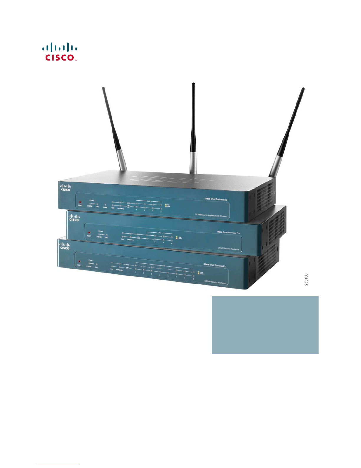
Feature Overview
The features of the SA 520, SA 520W, and the SA 540 are compared in the
following table.
Table 1 Comparison of SA 500 Series Security Appliance Models
Feature SA 520 SA 520W SA 540
Firewall
Performance
200 Mbps 200 Mbps 300 Mbps
UTM 200 Mbps 200 Mbps 300 Mbps
VPN
Performance
Connections 15,000 15,000 40,000
Cisco SA 500 Series Security Appliances Administration Guide 10
65 Mbps 65 Mbps 85 Mbps
Page 11
Getting Started
Feature Overview
1
Feature SA 520 SA 520W SA 540
LAN Ports 448
Wireless
(802.11n)
IPsec (# seats) Yes (50) Yes (50) Yes (100)
SSL (# seats) Includes 2 seats.
No Yes No
Included (50)
With license, up
to 25 seats.
Includes 2 seats.
With license, up
to 25 seats.
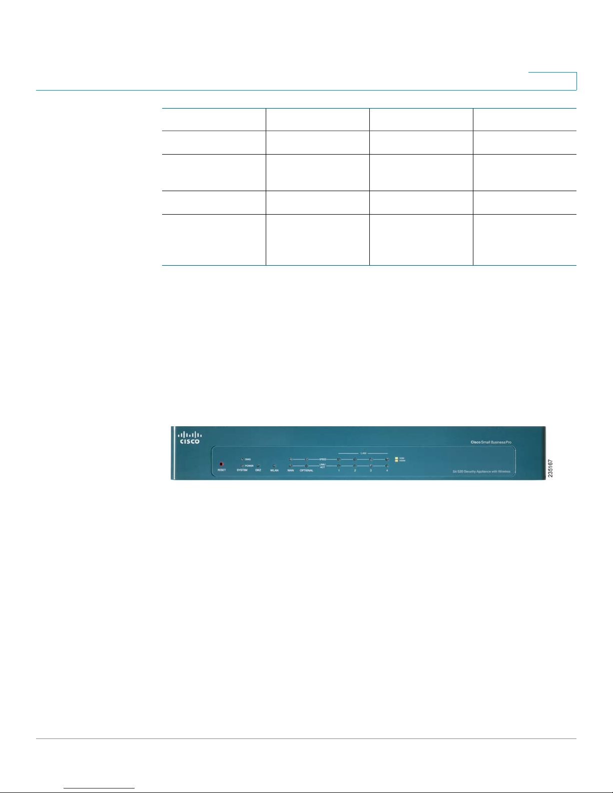
Device Overview
Before you begin to use the security appliance, become familiar with the LEDs on
the front panel and the ports on the rear panel. Refer to the following illustrations
and descriptions.
Front Panel
RESET Button—To reboot the security appliance, push and release the Reset
button. To restore the factory default settings, press and hold the Reset button for
5 seconds.
DIAG LED—(Orange) When lit, indicates the appliance is performing the power-on
diagnostics. When off, indicates the appliance has booted properly.
POWER LED—(Green) When lit, indicates the appliance is powered on.
DMZ LED—(Green) When lit, indicates the Optional port is configured as a
Demilitarized Zone or Demarcation Zone, which allows public services such as
web servers, without exposing your LAN.
SPEED LED—(Green or Orange) Indicates the traffic rate for the associated port.
Off = 10 Mbps, Green = 100 Mbps, Orange = 1000 Mbps.
Cisco SA 500 Series Security Appliances Administration Guide 11
Page 12
Getting Started
Feature Overview
1
LINK/ACT LED—(Green) When lit, indicates that a connection is being made
through the port. When flashing, the port is active.
WLAN LED—(Green) When lit, indicates that wireless is enabled (SA 520W).
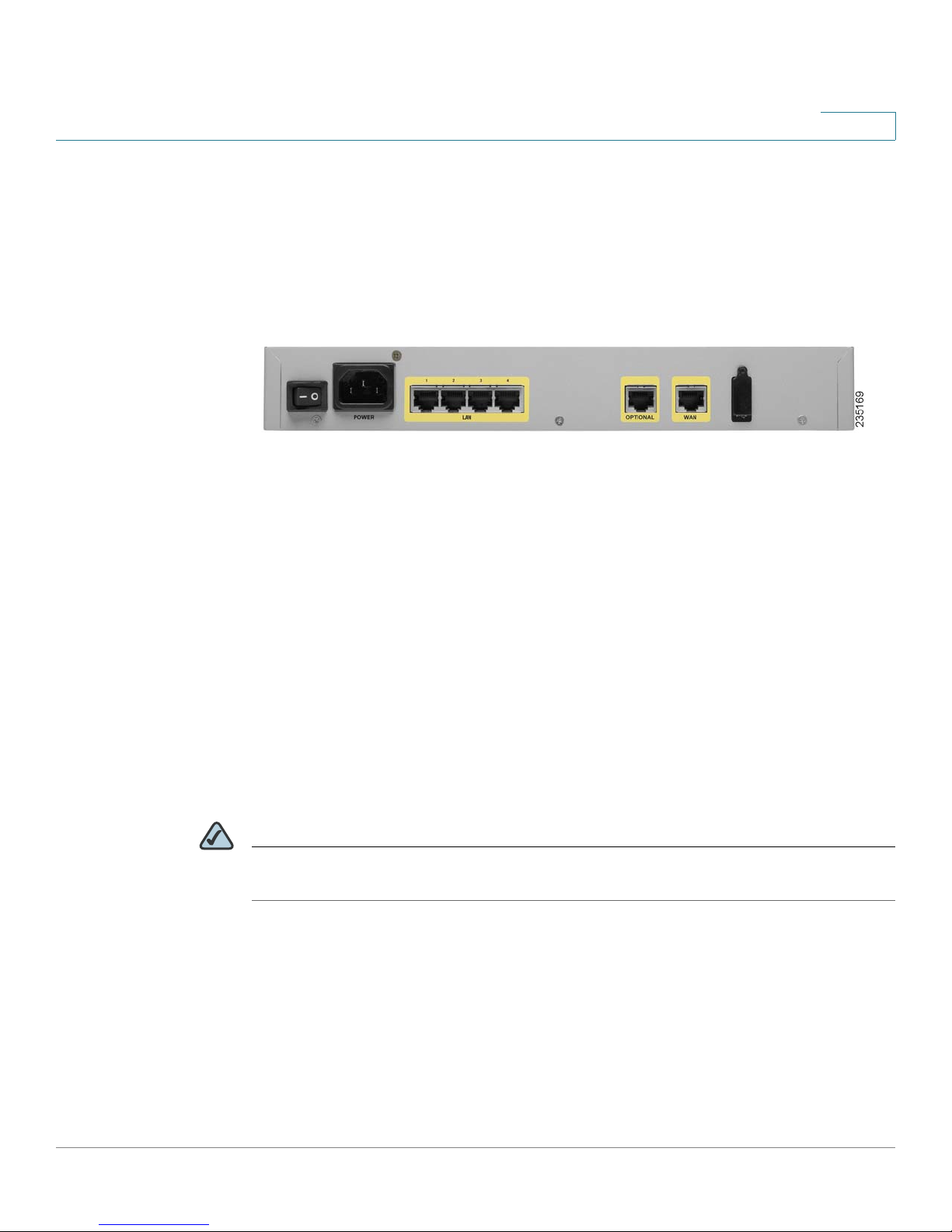
Rear Panel
POWER Switch—Turns the security appliance on or off.
POWER Connector—Connects the security appliance to power using the
supplied power cable.
LAN Ports—Connect computers and other network appliances to the security
appliance. The SA 520 and SA 520W have 4 LAN ports. The SA 540 has 8.
OPTIONAL Port—Can be configured to operate as a WAN, LAN, or DMZ port. A
DMZ (Demilitarized Zone or Demarcation Zone) can be configured to allow public
access to services such as web servers without exposing your LAN.
WAN Port—Connects the security appliance to DSL, a cable modem, or another
WAN connectivity device.
USB Port—Connects the security appliance to a USB device. You can use a USB
device to store configuration files for backup and restore operations.
NOTE The back panel of the SA 520W includes three threaded connectors for the
antennas.
Cisco SA 500 Series Security Appliances Administration Guide 12
Page 13

Getting Started
Installation
Installation
1
This section guides you through the installation of your security appliance. Refer to
the following topics:
• Installation Options, page 13
• Hardware Installation, page 16
Installation Options
You can place your security appliance on a desktop, mount it on a wall, or mount it
in a rack.
Placement Tips
• Ambient Temperature—To prevent the security appliance from
overheating, do not operate it in an area that exceeds an ambient
temperature of 104°F (40°C).
• Air Flow—Be sure that there is adequate air flow around the device.
• Mechanical Loading—Be sure that the security appliance is level and
stable to avoid any hazardous conditions.
To place the security appliance on a desktop, install the four rubber feet (included)
on the bottom of the security appliance. Place the device on a flat surface.
Cisco SA 500 Series Security Appliances Administration Guide 13
Page 14
Getting Started
Installation
1
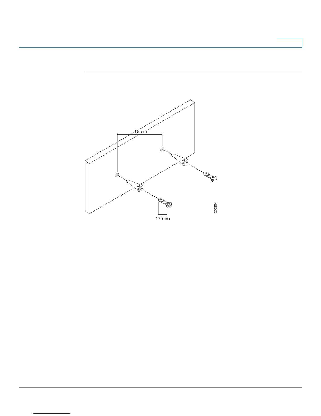
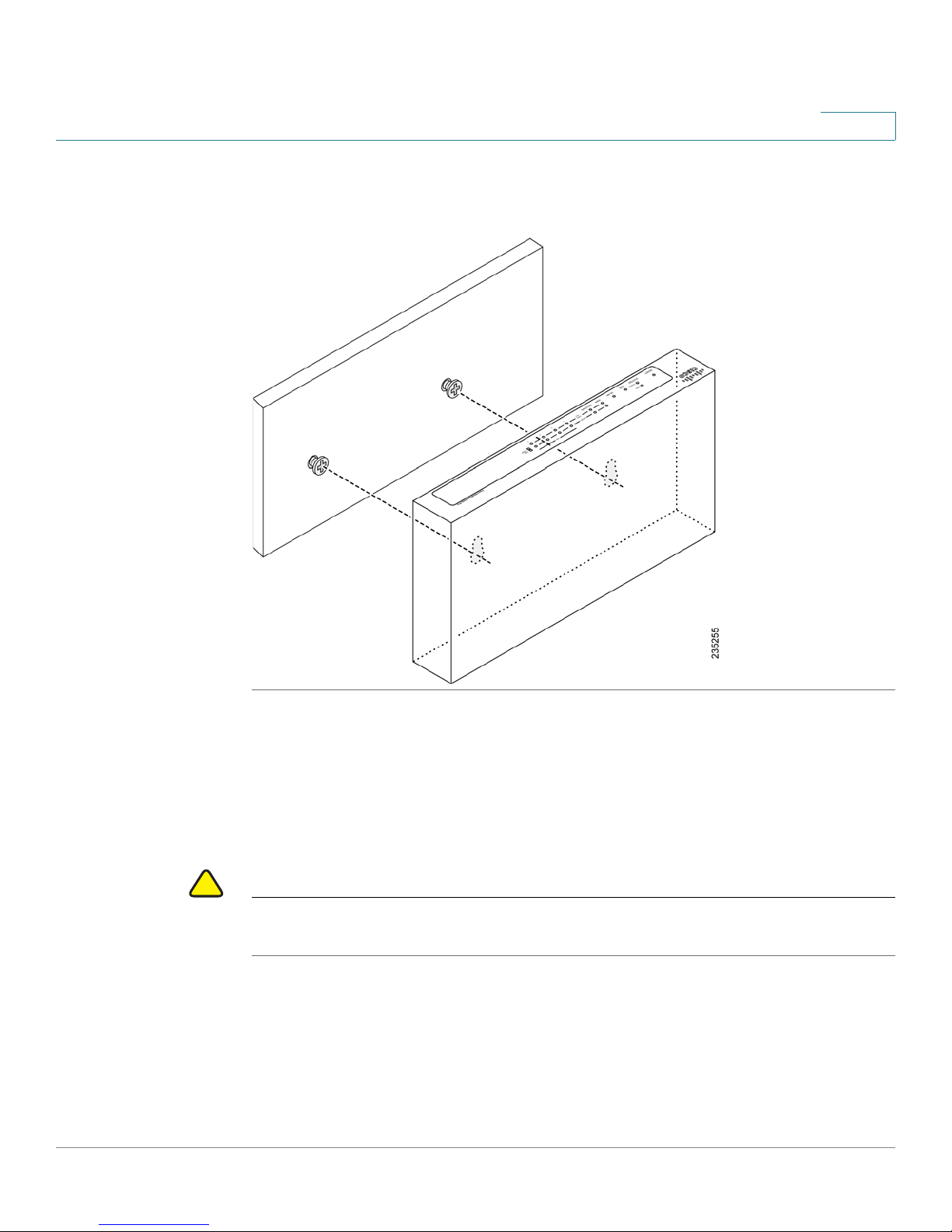
Wall Mounting
STEP 1 Insert two 17 mm screws, with anchors, into the wall 15 cm apart (about 5.9
inches). Leave 3-4 mm (about 1/8 inch) of the head exposed.
Cisco SA 500 Series Security Appliances Administration Guide 14
Page 15
Getting Started
!
Installation
1
STEP 2 Position the unit so that the wall-mount slots are over the two screws. Slide the unit
down until the screws fit snugly into the wall-mount slots.
Rack Mounting
You can mount the security appliance in any standard size, 19-inch (about 48 cm)
wide rack. Each security appliance requires 1 rack unit (RU) of space, which is 1.75
inches (44.45 mm) high.
CAUTION Do not overload the power outlet or circuit when installing multiple devices in a
rack.
Cisco SA 500 Series Security Appliances Administration Guide 15
Page 16

Getting Started
Installation
1
STEP 1 Remove the four screws from each side of the security appliance.
STEP 2 Place one of the supplied spacers on the side of the security appliance so that the
four holes align to the screw holes. Place a rack mount bracket next to the spacer
and reinstall the screws.
NOTE If the screws are not long enough to reattach the bracket with the spacer,
attach the bracket directly to the case without the spacer.
STEP 3 Install the security appliance into a standard rack as shown.
Hardware Installation
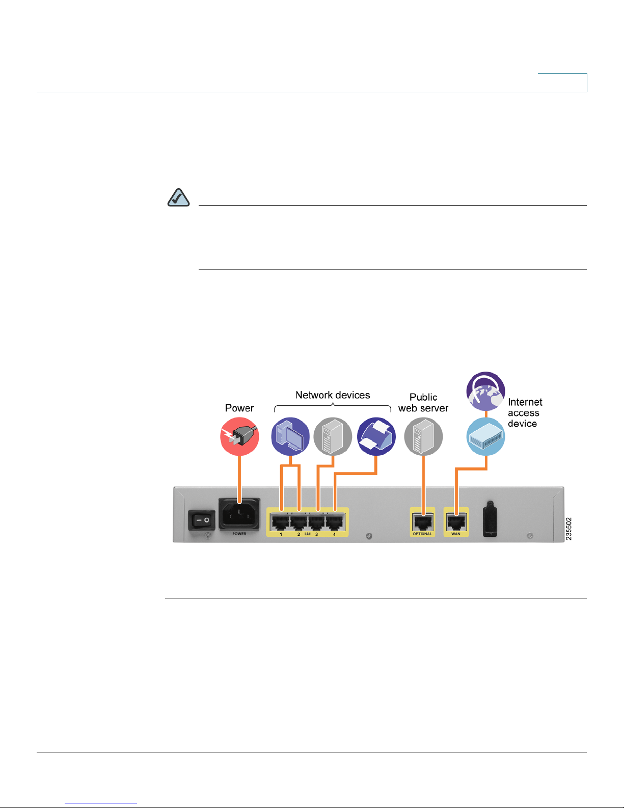
Follow these steps to connect the equipment:
STEP 1 Connect the security appliance to power.
STEP 2 If you are installing the SA 520W, screw each antenna onto a threaded connector
on the back panel. Orient each antenna to point upward.
STEP 3 For DSL, a cable modem, or other WAN connectivity devices, connect an Ethernet
network cable from the device to the WAN port on the back panel. Cisco strongly
recommends using Cat5E or better cable.
Cisco SA 500 Series Security Appliances Administration Guide 16
Page 17
Getting Started
Installation
1
STEP 4 For network devices, connect an Ethernet network cable from the network device
to one of the dedicated LAN ports on the back panel.
STEP 5 For a UC 500, connect an Ethernet network cable from the WAN port of the UC 500
to an available LAN port of the security appliance.
NOTE For details about configuring the UC 500 and the security appliance to work
together, see the SA 500 Series Security Appliances Administration Guide
on Cisco.com. See the documentation links in the “Where to Go From
Here” section of this guide.
STEP 6 Power on the security appliance.
STEP 7 Power on the connected devices. Each LED lights to show an active connection.
A sample configuration is illustrated below.
Congratulations! The installation of the security appliance is complete.
Cisco SA 500 Series Security Appliances Administration Guide 17
Page 18

Getting Started
Getting Started with the Configuration Utility
Getting Started with the Configuration Utility
The Configuration Utility web page is a web based device manager that is used to
provision the SA 500 Series Security Appliances. To use this utility, you must be
able to connect to the SA 500 Series Security Appliances from your administration
PC or laptop. You can access the router by using any web browser (such as
Microsoft Internet Explorer or Mozilla Firefox).
Connecting to the Configuration Utility
STEP 1 Connect your computer to an available LAN port on the back panel of the security
appliance.
STEP 2 Start a web browser, and enter the following address: 192.168.75.1
1
NOTE The above address is the factory default LAN address of the security
appliance. If you change this setting in the LAN configuration, you will need
to enter the new IP address to connect to the Configuration Utility.
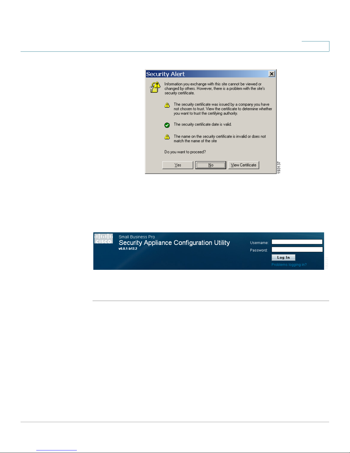
STEP 3 When the Security Alert appears, accept or install the certificate:
• Internet Explorer: Click Ye s to proceed, or click View Certificate for details.
On the Certificate page, click Install the Certificate. Follow the instructions
in the Wizard to complete the installation.
• Firefox: Click the link to add an exception. Click the Add Exception button.
Click Get Certificate, and then click Confirm Security Exception.
• Safari: Click Continue to proceed, or click Show Certificate. On the
Certificate page, click Install the Certificate. Follow the instructions in the
Wizard to complete the installation.
Cisco SA 500 Series Security Appliances Administration Guide 18
Page 19
Getting Started
Getting Started with the Configuration Utility
STEP 4 Enter the default user name and password:
1
• Username: cisco
• Password: cisco
STEP 5 Click Log In. The Getting Started (Basic) page appears. For more information, see
Using the Getting Started Pages, page 20.
You can use the Cisco Configuration Assistant to launch the Configuration Utility if
you are using the security appliance with a CCA-supported device, such as the
UC 500. For more information about CCA, see: www.cisco.com/go/configassist.
Cisco SA 500 Series Security Appliances Administration Guide 19
Page 20
Getting Started
Getting Started with the Configuration Utility
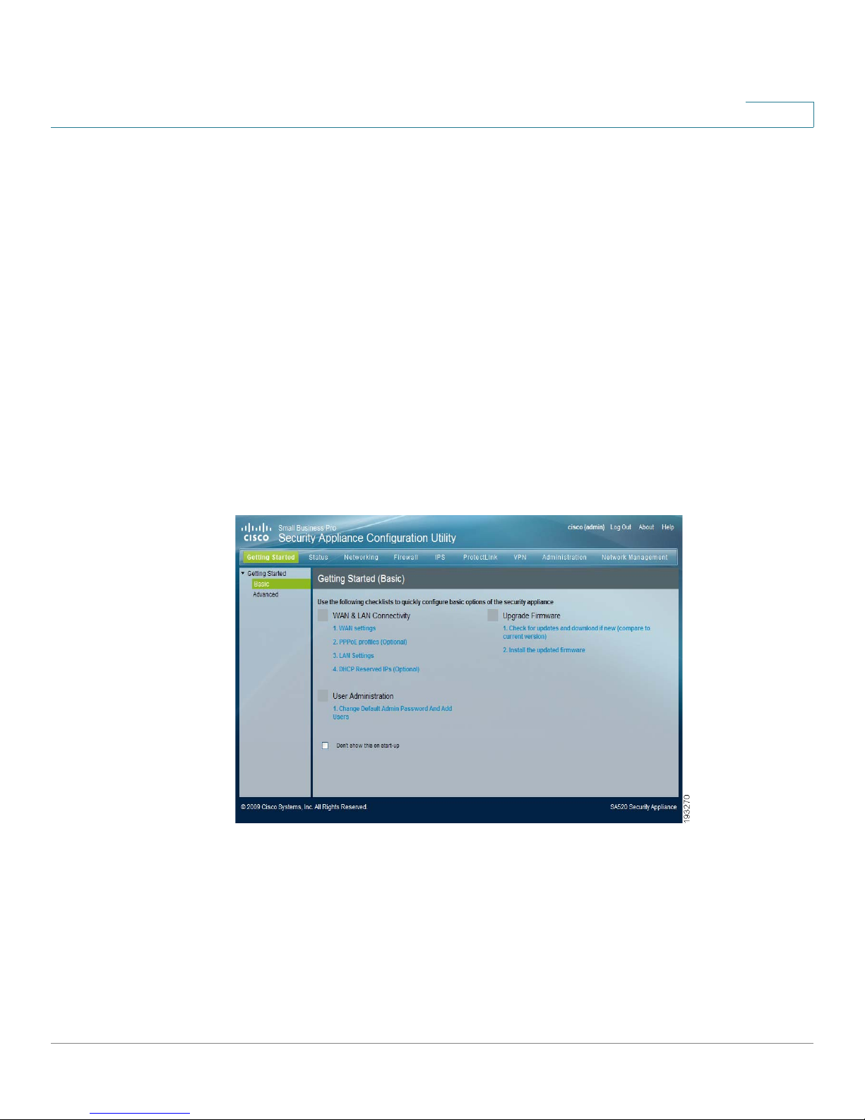
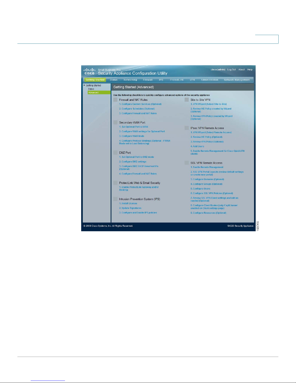
Using the Getting Started Pages
The Getting Started pages provide help with common configuration tasks.
• Find a task that you need to perform, and then click a link to get started.
Proceed in order through the listed links.
• To return to the Getting Started (Basic) page at any time, click the Getting
Started button in the menu bar.
• For help with advanced configuration tasks, such as firewall/NAT
configuration, optional WAN configuration, DMZ configuration, and VPN
setup, click the Getting Started > Advanced link in the navigation pane,
and click the links to perform the tasks that you want to complete.
• If you want to prevent the Getting Started (Basic) page from appearing
automatically after you log in, check the Don’t show this on start-up box at
1
Figure1 Getting Started (Basic) Page
Cisco SA 500 Series Security Appliances Administration Guide 20
Page 21
Getting Started
Getting Started with the Configuration Utility
Figure 2 Getting Started (Advanced) Page
1
Cisco SA 500 Series Security Appliances Administration Guide 21
Page 22
Getting Started
Getting Started with the Configuration Utility
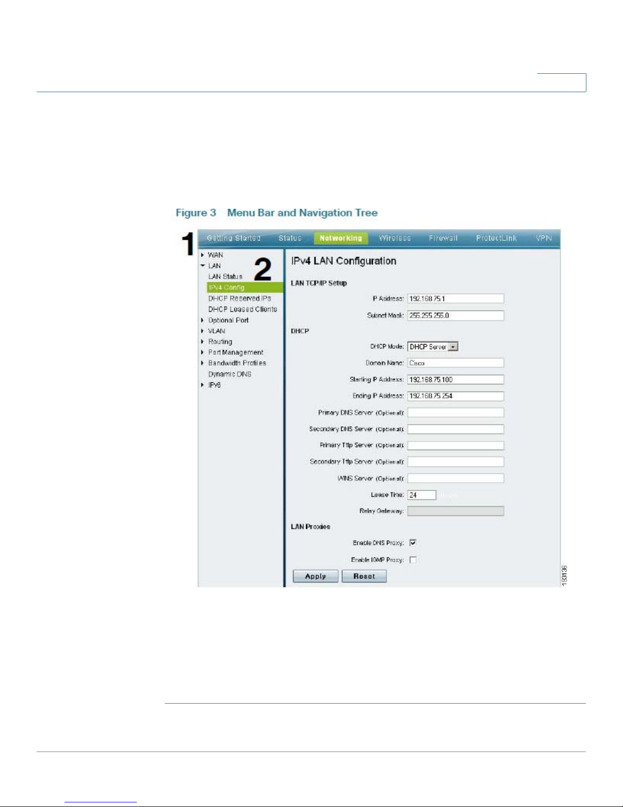
Navigating Through the Configuration Utility
Use the menu bar and the navigation tree to perform tasks in the Configuration
Utility.
Figure 3 Menu Bar and Navigation Tree
1
1. Menu Bar : Click an item in the menu bar at the top of the page to choose a
module of the Configuration Utility.
2. Navigation Tree: Top-level links are indicated by arrows. Click a top-level link to
open a list of options. Then click a link in the list to open a page where you can
review or modify the configuration.
Cisco SA 500 Series Security Appliances Administration Guide 22
Page 23
Getting Started
Getting Started with the Configuration Utility
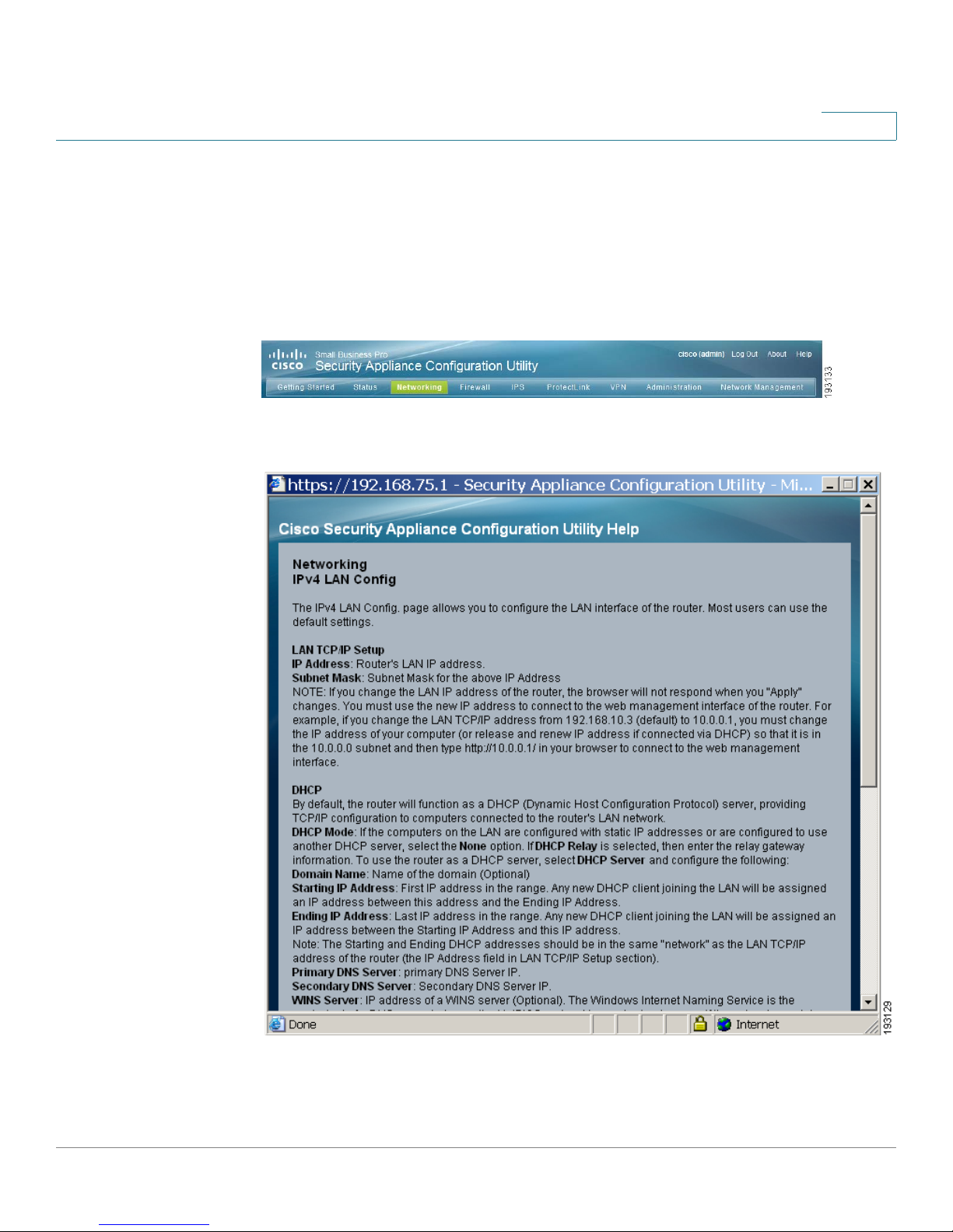
Using the Help System
The Configuration Utility includes detailed Help files for all configuration tasks. To
view a Help page, click the Help link in the top right corner of the screen. A new
window appears with information about the page that you are currently viewing.
Figure 4 Help Link
Figure 5 Sample Help Screen
1
Cisco SA 500 Series Security Appliances Administration Guide 23
Page 24

Getting Started
About the Default Settings
About the Default Settings
The SA 500 Series Security Appliances are pre-configured with settings that
allow you to start using the device with minimal changes needed. Depending on
the requirements of your Internet Service Provider (ISP) and the needs of your
business, you might need to modify some of these settings. You can use the
Configuration Utility to customize all settings, as needed.
Settings of particular interest are described below. For a full list of all factory
default settings, see Appendix D, “Factory Default Settings.”
• IPv4 Addressing: By default, the security appliance is in IPv4 Only mode. If
you want to use IPv6 addressing, first enable IPv6 mode and then configure
your IPv6 WAN and your IPv6 LAN. See Configuring IPv6 Addressing,
page 92.
1
• WAN Configuration: By default, the security appliance is configured to
obtain an IP address from your ISP by using Dynamic Host Configuration
Protocol (DHCP). If your ISP assigned a static IP address, you will need to
configure it. In addition, if your ISP requires a login every time that you
connect to the Internet, you will need to enter the account information. You
can change other WAN settings as well. For more information, see Scenario
1: Basic Network Configuration with Internet Access, page 28.
• LAN Configuration: By default, the LAN interface acts as a DHCP server for
all connected devices. For most deployment scenarios, the default DHCP
and TCP/IP settings of the security appliance should be satisfactory.
However, you can change the subnet address, or the default IP address of
the security appliance. You can assign static IP addresses to connected
devices rather than allowing the security appliance to act as a DHCP server.
For more information, see Scenario 1: Basic Network Configuration with
Internet Access, page 28.
• Optional Port: This port is preset to act as a secondary WAN port.
Alternatively, you can configure the Optional port for use as a DMZ port or
an extra LAN port. See Scenario 1: Basic Network Configuration with
Internet Access, page 28 or Scenario 4: DMZ for Public Web Sites and
Services, page 32.
• Wireless Network (SA 520W only): The SA 520W is configured with an
access point named AP1, which has the default network name of Cisco_1.
The access point is enabled by default. The security profile has Open
security and identifies itself to all wireless devices that are in range. These
settings make it easy for you to begin using your wireless network.
Cisco SA 500 Series Security Appliances Administration Guide 24
Page 25

Getting Started
Basic Tasks
Basic Tasks
1
However, for security purposes, it is strongly recommended that you
configure the profile with the appropriate security settings. See Scenario 7:
Wireless Networking, page 37.
• Administrative Access: You can access the Configuration Utility by using a
web browser and entering the default IP address of 192.168.75.1. You can
log on by entering cisco for the username and cisco for the password. You
are strongly encouraged to change the default username and password.
You can also change the default Idle Timeout setting. The default setting
requires logging in again after 10 minutes of inactivity. For more information
about these settings, see Changing the Default User Name and
Password, page 25.
It is strongly recommended that you complete the following basic tasks before you
begin configuring your security appliance.
Changing the Default User Name and Password
To prevent unauthorized access, immediately change the user name and
password for the default Administrator account.
STEP 1 In the User Administration section of the Getting Started (Basic) page, click
Change Default Admin Password And Add Users.
The Users page appears.
STEP 2 In the first row of the table, find the default Administrator account.
STEP 3 Click the button in the Edit column. The User Configuration page appears,
displaying the default information.
STEP 4 Enter the following information:
• User Name: Enter a unique identifier for the user. It can include any
alphanumeric characters.
• First Name: Enter the user’s first name.
• Last Name: Enter the user’s last name.
Cisco SA 500 Series Security Appliances Administration Guide 25
Page 26

Getting Started
Basic Tasks
1
NOTE The User Type and Group cannot be changed for this account.
• Check to Edit Password: Check this box to enable the password fields.
• Enter Your Password: Enter the current password. The default password
for this new security appliance is cisco.
• New Password: Enter a password that contains alphanumeric, ‘—’ or ‘_’
characters.
• Confirm Password: Enter the password again.
• Idle Timeout: Enter the time in minutes that the user can be inactive before
the login expires. You can enter any value from 0 to 999.
STEP 5 Click Apply to save your settings, or click Reset to revert to the saved settings.
Backing Up Your Configuration
At any point during the configuration process, you can back up your configuration.
Later, if you make changes that you want to abandon, you easily can easily revert
to a saved configuration. For more information, see Upgrading Firmware and
Working with Configuration Files, page 199.
Upgrading the Firmware
Before you do any other tasks, you should upgrade your firmware to ensure that
you are using the latest version. You can upgrade from a file stored on your
computer, your network, or a USB key.
STEP 1 In the Upgrade Firmware section of the Getting Started (Basic) page, click the link:
Check for updates and download if new
STEP 2 When the web page appears, download the latest software.
NOTE You also can find new firmware for the SA 500 Series Security Appliances at
the following website: www.cisco.com/go/sa500software
Cisco SA 500 Series Security Appliances Administration Guide 26
Page 27

Getting Started
Common Configuration Scenarios
STEP 3 In the Upgrade Firmware section of the Getting Started (Basic) page, click the
Install the updated firmware link.
The Firmware & Configuration (Network) page appears.
STEP 4 In the Firmware Upgrade area, click Browse. Find the file that you downloaded.
STEP 5 Click Upload.
NOTE Wait while the firmware is upgraded.
1
1. Do NOT close the browser window.
2. Do NOT go online.
3. Do NOT turn off or power-cycle the router.
4. Do NOT shutdown the computer.
The router will take several minutes to complete the upgrade. While the upgrade is
in progress, the Test LED on the front panel of the router is lit. When the upgrade is
complete, the router automatically restarts.
Common Configuration Scenarios
The SA 500 Series Security Appliances can be deployed to address the security
concerns of your business. As you get started using your security appliance,
consider the following configuration scenarios:
• Scenario 1: Basic Network Configuration with Internet Access, page 28
• Scenario 2: Cisco Smart Business Communications System
Configuration, page 30
• Scenario 4: DMZ for Public Web Sites and Services, page 32
• Scenario 3: Firewall for Controlling Inbound and Outbound Traffic,
page 31
• Scenario 6: Site-to-Site Networking and Remote Access, page 33
• Scenario 7: Wireless Networking, page 37
Cisco SA 500 Series Security Appliances Administration Guide 27
Page 28
Getting Started
Common Configuration Scenarios
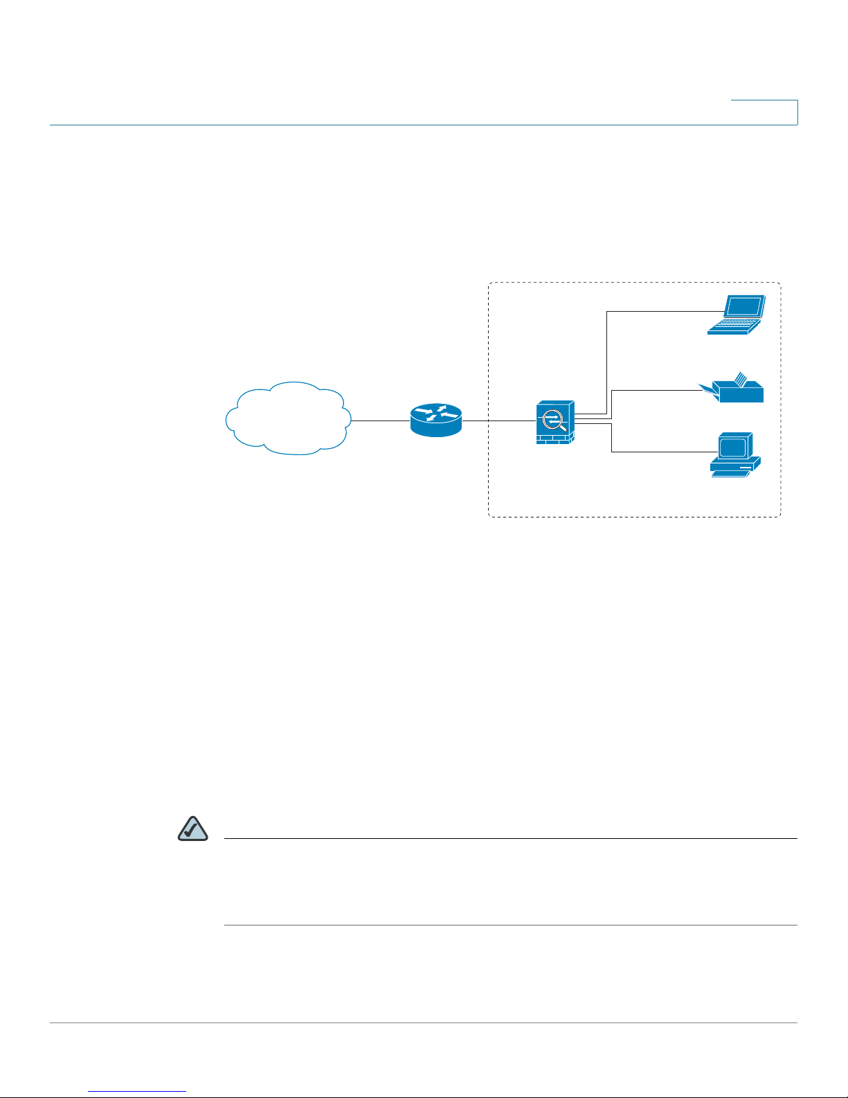
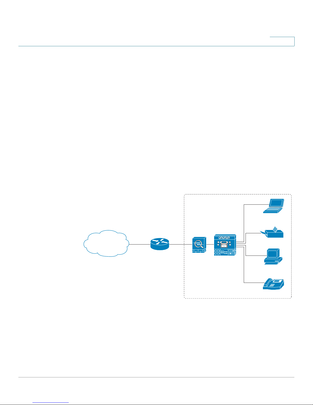
Scenario 1: Basic Network Configuration with Internet
Access
Outside Network
1
Laptop
computer
Private Network
Internet
Internet
Access Device
SA 500
Printer
Personal
computer
In a basic deployment for a small business, the security appliance enables
communication between the devices on the private network and also allows
computers to access the Internet. With the default settings, the security appliance
gets its WAN address dynamically from the ISP. All devices on the LAN receive
their IP addresses dynamically from the security appliance. All devices have
access to the Internet, but no inbound traffic is allowed from the Internet to any
LAN devices.
Configuration tasks for this scenario:
The default configuration is sufficient for many small businesses, and you might
not need to change any of the WAN or LAN settings. However, depending on the
requirements of your ISP, as well your preferences for your LAN configuration, you
can make changes, as needed.
235234
NOTE Before you configure your network, make sure that you have upgraded the
firmware (see Upgrading the Firmware, page 26) and changed the default
Administrator password (see Changing the Default User Name and Password,
page 25).
Cisco SA 500 Series Security Appliances Administration Guide 28
Page 29

Getting Started
Common Configuration Scenarios
Consider the following first steps:
1. Review the WAN configuration and make any changes that are needed to set up
your Internet connection.
In the WAN & LAN Connectivity section of the Getting Started (Basic) page,
click the WAN settings link. For more information, see Configuring the WAN
Connection, page 50.
2. Review the LAN configuration and make any changes that are needed to
support your network. The default DHCP and TCP/IP settings should be
satisfactory in most cases. However, you can change the subnet address or the
default IP address, or assign static IP addresses to your devices.
In the WAN & LAN Connectivity section of the Getting Started (Basic) page,
click the LAN Settings link. For more information, see Configuring the LAN,
page 56.
1
3. If you are going to use your security appliance with your Cisco Smart Business
Communications System (SBCS), install and configure your UC 500.
See Scenario 2: Cisco Smart Business Communications System
Configuration, page 30.
4. Consider how you want to use the Optional port:
• If you need to host public services such as web sites, you will need a DMZ.
For more information, see Scenario 4: DMZ for Public Web Sites and
Services, page 32. For information about using the optional port as an extra
LAN port, see Configuring the Optional Port as a LAN Port, page 61.
• If you have two ISP links and do not need a DMZ, you can use the Optional
port as a secondary WAN port to provide backup connectivity or load
balancing. To configure the port, use the links in the Secondary WAN Port
section of the Getting Started (Advanced) page. For more information, see
Configuring the Optional WAN, page 62.
• If you do not need a DMZ or a secondary WAN, you can use the Optional
port as an extra LAN port. For more information, see Configuring the
Optional Port as a LAN Port, page 61.
5. If you want to allow inbound access from the Internet, or if you want to restrict
some types of outbound traffic to the Internet, configure your firewall rules.
See Scenario 3: Firewall for Controlling Inbound and Outbound Traffic,
page 31.
Cisco SA 500 Series Security Appliances Administration Guide 29
Page 30
Getting Started
235235
Personal
computer
Internet
Access Device
Laptop
computer
Printer
Private Network
SA 500
UC500
IP Phone
Outside Network
Internet
IP
Common Configuration Scenarios
6. Consider whether you need to allow access to your network from remote sites
or remote workers.
See Scenario 6: Site-to-Site Networking and Remote Access, page 33.
7. Consider whether you need to enable features such as logging or remote
access to the configuration utility.
See the following topics:
• Configuring the Logging Options, page 208
• RMON (Remote Management), page 215
Scenario 2: Cisco Smart Business Communications System
Configuration
1
You can use the security appliance to protect your Cisco Smart Business
Communications System network.
Configuration tasks for this scenario:
See Scenario 1: Basic Network Configuration with Internet Access,
page 28.
1. Configure the WAN and LAN settings for your security appliance, as needed.
2. Connect a cable from the WAN port of the UC 500 to an available LAN port of
the security appliance.
Cisco SA 500 Series Security Appliances Administration Guide 30
Page 31

Getting Started
Common Configuration Scenarios
With the default configuration, the security appliance acts as a DCHP server
that assigns IP addresses in the range of 192.168.75.x. IP Phones are assigned
IP addresses in the address range 10.1.1.x/24.
3. If you want to assign a static IP address to the UC 500 or other LAN devices,
click the DHCP Reserved IPs link under WAN & LAN Connectivity on the
Getting Started (Basic) page. For more information, see DHCP Reserved IPs,
page 60.
4. Configure a static IP route from the security appliance to the UC 500 data
VLANs (192.168.10.x). For more information, see Static Routing, page 84.
5. Because the security appliance will provide the firewall, Network Address
Translation (NAT), and SIP Application Layer Gateway (SIP-ALG) for your
network, disable those functions on the UC 500. For instructions, refer to the
documentation or online Help for the Cisco Configuration Assistant (CCA).
1
Scenario 3: Firewall for Controlling Inbound and Outbound
Traffic
By default, all outbound traffic is allowed and all inbound traffic is denied. If you
want to deny some outbound traffic or allow some inbound traffic, you will need to
configure a firewall rule. To prevent unwanted traffic from the Internet, and to
ensure that your employees are using the Internet for approved business
purposes, you can configure various levels of firewall rules. You can configure
rules that apply to a specified IP address, a range of IP addresses, or to everyone
globally.
Consider the following examples of firewall rules:
• Block outbound traffic to certain websites
• Restrict Internet access for certain users
• Allow inbound traffic to your DMZ
• Configure advanced NAT routing
For these scenarios and all situations in which you need an exception from the
default firewall policy, you need to configure firewall rules.
NOTE The default WAN and LAN settings might be sufficient for your deployment, but
consider the steps outlined in Scenario 1: Basic Network Configuration with
Internet Access, page 28.
Cisco SA 500 Series Security Appliances Administration Guide 31
Page 32

Getting Started
Common Configuration Scenarios
Configuration tasks for this scenario:
To start configuring your firewall rules, use the Firewall and NAT Rules links on the
Getting Started (Advanced) page. For more information, see Configuring Firewall
Rules to Control Inbound and Outbound Traffic, page 121.
Scenario 4: DMZ for Public Web Sites and Services
If your business hosts public services such as web sites, you need a way to allow
access to those services without exposing your LAN. You can address this
concern by configuring the Optional port of the security appliance for use as a
DMZ (Demarcation Zone or Demilitarized Zone). This zone acts as a separate
network between your private LAN and the Internet. After you configure your DMZ,
you can configure the firewall rules that enable traffic to connect only to the
services that you specify.
1
www.example.com
Public IP Address
209.165.200.225
SA 500
LAN Interface
192.168.75.1
Internet
Source Address Translation
209.165.200.225 172.16.2.30
DMZ Interface
172.16.2.1
Web Server
Private IP Address: 172.16.2.30
Public IP Address: 209.165.200.225
User
192.168.75.10
Cisco SA 500 Series Security Appliances Administration Guide 32
User
192.168.75.11
235140
Page 33

Getting Started
Common Configuration Scenarios
NOTE The default WAN and LAN settings might be sufficient for your deployment, but
consider the steps outlined in Scenario 1: Basic Network Configuration with
Internet Access, page 28.
Configuration tasks for this scenario:
To start configuring a DMZ, use the links in the DMZ Port section of the Getting
Started (Advanced) page. For more information, see Configuring a DMZ, page 70.
Scenario 5: Configuring ProtectLink Web & Email Security
For added protection against web and email threats, the security appliance
supports Trend Micro™ ProtectLink™ Gateway services. Trend Micro™
ProtectLink™ Gateway offers comprehensive spam and Web Protection at your
Cisco security appliance. This service integrates anti-spam with antivirus and antispyware, and Web Reputation with URL Filtering. As a result, your network is
protected from email threats in the Internet “cloud” and web threats in the Cisco
security appliance, providing access only to email and websites that are
appropriate for your business.
1
Configuration tasks for this scenario:
In the ProtectLink Web & Email Security section of the Getting Started
(Advanced) page, click Enable ProtectLink Gateway. The Protect Link page
appears. For more information, see Chapter 7, “Using Cisco ProtectLink
Security Services.” Also refer to the Cisco Small Business ProtectLink Gateway
Administration Guide.
Scenario 6: Site-to-Site Networking and Remote Access
You can configure a Virtual Private Network (VPN) to extend your network to other
sites or to allow business partners and teleworkers to access applications and
network resources.
You can configure the following types of VPNs:
• IPSec VPN for a Site-to-Site Tunnel
• IPSec VPN for Remote Access with a VPN Client
• SSL VPN for Remote Access with a Web Browser
Cisco SA 500 Series Security Appliances Administration Guide 33
Page 34

Getting Started
235142
Site A
SA 500 SA 500
Site B
Inside
10.10.10.0
Outside
209.165.200.226
Outside
209.165.200.236
Inside
10.20.20.0
Personal
computers
Personal
computers
Printer Printer
Internet
Common Configuration Scenarios
IPSec VPN for Site-to-Site VPN
For site-to-site VPN, you can configure an IPSec tunnel with advanced encryption
to maintain network security.
1
Configuration tasks for this scenario:
In the Site-to-Site VPN section of the Getting Started (Advanced) page, click the
VPN Wizard link. When the VPN Wizard appears, choose the Site-to-Site option
and enter the other settings. Optionally, you can use other links on the Getting
Started (Advanced) page to review and modify the policies that were created by
the Wizard. For more information, see Configuring an IPSec VPN Tunnel for
Remote Access with a VPN Client, page 157.
Cisco SA 500 Series Security Appliances Administration Guide 34
Page 35

Getting Started
Common Configuration Scenarios
IPSec VPN Remote Access with a VPN Client
For remote access by users who have an IPSec VPN client on the PC, you can
configure an IPSec VPN client tunnel for secure access. This option requires
installing and maintaining the VPN client software for these remote sites and users.
10.10.10.163
1
DNS Server
Personal Computer
Using VPN Software Client
Personal Computer
Using VPN Software Client
Personal Computer
Using VPN Software Client
235236
Internal
network
WINS Server
10.10.10.133
Inside
10.10.10.0
Security
Appliance
Outside
Internet
Configuration tasks for this scenario:
In the IPsec VPN Remote Access section of the Getting Started (Advanced)
page, click the VPN Wizard link. When the VPN Wizard appears, choose the
Remote Access option and complete the fields on the page. Return to the Getting
Started (Advanced) page and click Add Users to add your VPN users. Optionally,
you can use other links on the Getting Started (Advanced) page to review and
modify the policies that were created by the Wizard. For more information, see
Configuring an IPSec VPN Tunnel for Remote Access with a VPN Client,
page 157.
Cisco SA 500 Series Security Appliances Administration Guide 35
Page 36

Getting Started
235141
Inside
10.10.10.0
Outside
Security
Appliance
DNS Server
10.10.10.163
WINS Server
10.10.10.133
Internet
Internal
network
Clientless VPN
Clientless VPN
Clientless VPN
Common Configuration Scenarios
SSL VPN Remote Access With a Web Browser
For remote access by users who have no special software on the PC, such as
contractors who need access to some or all of your network resources, SSL VPN
is a flexible and secure way to extend your network resources. You are not
responsible for any VPN client software, since the VPN tunnel can be accessed by
anyone with a web browser, Internet access, and the correct login credentials.
1
Configuration tasks for this scenario:
In the SSL VPN Remote Access section of the Getting Started (Advanced) page,
click the SSL VPN Portal Layouts link to review the default settings for the user
portal. Create new portals for different user groups, if needed. Return to the
Getting Started (Advanced) page and click the Configure Users link to add your
VPN users. Optionally, you can use other links to configure the policies, client
settings, routes, and resources for your SSL VPN. For more information, see
Configuring SSL VPN for Browser-Based Remote Access, page 172.
Cisco SA 500 Series Security Appliances Administration Guide 36
Page 37

Getting Started
Common Configuration Scenarios
Scenario 7: Wireless Networking
With the SA 520W, you can configure your wireless network to meet the demands
of your physical environment and to control access to your network resources.
Outside Network
Private Network
1
Laptop
computer
Internet
ISP Router
SA 500
Printer
Personal
computer
IP
IP Phone
Configuration tasks for this scenario:
1. The default WAN and LAN settings might be sufficient for your deployment, but
consider the steps outlined for Scenario 1: Basic Network Configuration with
Internet Access, page 28.
2. Although you can begin using your wireless network right away, you should
configure the security settings to protect your network and the data that you
transmit. To configure your wireless network, see Chapter 4, “Wireless
Configuration for the SA 520W.”
235237
Cisco SA 500 Series Security Appliances Administration Guide 37
Page 38

Status
2
You can use the Status pages to review the status of your security appliance and
to view logs.
• Device Status, page 38
• VPN Status, page 43
• Active Users, page 48
Device Status
• View Logs Status, page 46
• CDP Neighbor, page 49
• LAN Devices, page 49
The Device Status section includes the following pages:
• Device Status, page 38
• Port Statistics, page 41
• Wireless Statistics for the SA 520W, page 41
Device Status
Use this page to view the current system information. To open this page, click
Status on the menu bar, and then click Device Status in the navigation tree.
System Info
• System Name: The name of the device.
• Primary Firmware Version: The version of the firmware that the router is
currently using. By default, the router will boot from this version.
Cisco SA 500 Series Security Appliances Administration Guide 38
Page 39

Status
Device Status
2
• Secondary Firmware Version: The previous version of firmware that was in
use before the most recent upgrade. To switch to the secondary firmware
version, see Using the Secondary Firmware, page 203.
• Latest Image Available: Displays the latest image available for your device.
This field is only displayed if automatic update is enabled from the
Firmware & Configuration Network page. For more information see
Upgrading Firmware and Working with Configuration Files, page 199.
• Link to Release Notes: Provides a link to the firmware release notes on
Cisco.com.
• Time at which Last Query was made: The time when the firmware check
was last performed.
ProtectLink License Info
The status of the optional ProtectLink service, and account information, if
applicable.
LAN Info
• MAC Address: The MAC address of the security appliance on the local
network.
• IP address: The IP address for the security appliance on the local network,
with the subnet mask for the local network.
• DHCP Status: The status of the security appliance’s DHCP server: enabled
or disabled. When DHCP is enabled, then the connected DHCP client
machines receive their IP addresses dynamically.
• DHCPv6 Status: The status of the security appliance’s DHCPv6 server:
enabled or disabled. If DHCPv6 is enabled, then the connected DHCPv6
client machines receive their IP addresses dynamically.
Dedicated WAN Info
This section displays information about the primary (dedicated) WAN port.
• MAC Address: The MAC address of the WAN port.
• IP Address: The IP address of the WAN port.
• IP Subnet Mask: The subnet mask for the WAN port.
• NAT: The status of NAT mode for the current operation: enabled or disabled.
If NAT is disabled, then the security appliance is in routing mode.
• Wan State: The status of the WAN connection: UP or DOWN.
Cisco SA 500 Series Security Appliances Administration Guide 39
Page 40

Status
Device Status
2
• IPv4 Connection Type: The method for obtaining a public IPv4 address.
The IP address may be obtained dynamically through a DHCP server or
may be assigned statically by the user.
• IPv6 Connection Type: The method for obtaining a public IPv6 address.
The IP address may be obtained dynamically through a DHCPv6 server or
may be assigned statically by the user.
• IPv4 Connection State: Indicates if the WAN port is connected or not
through IPv4 address.
• IPv6 Connection State: Indicates if the WAN port is connected or not
through IPv6 address.
• WAN Mode: Indicates whether the WAN mode is set to single port, load
balancing or auto rollover mode.
• Gateway: The Gateway IP address of the WAN port.
• Primary DNS: The primary DNS server IP address of the WAN port.
• Secondary DNS: The secondary DNS server IP address of the WAN port.
Optional Port Info
The Optional Port Info has the following information displayed for the port that the
user assigns to be a WAN, DMZ, or LAN port:
• Present Mode: The currently configured mode: WAN, DMZ, or LAN.
• MAC Address: The MAC address of the optional port.
• IP Address: The IP address of the optional port.
• NAT: If the optional port is in WAN mode, then this field indicates if the port
is used in NAT mode (enabled) or routing mode (disabled).
• Wan State: Indicates if the WAN connection is UP or DOWN.
• IPv4 Connection Type: Indicates if the optional port WAN IP address is
obtained dynamically through a DHCP server or assigned statically by the
user.
• Connection State: Indicates if the optional port is connected or not.
• WAN Mode: Indicates whether the WAN mode is set to single port, load
balancing or auto rollover mode.
• Gateway: The Gateway IP address of the Optional port.
Cisco SA 500 Series Security Appliances Administration Guide 40
Page 41

Status
Device Status
2
• Primary DNS: The primary DNS server IP address of the Optional port.
• Secondary DNS: The secondary DNS server IP address of the Optional
port.
Port Statistics
Use this page to view current statistics for the Dedicated WAN, Optional, LAN, and
WLAN ports. The page is updated every 10 seconds. To view this page, click
Status on the menu bar, and then click Device Status > Port Statistics in the
navigation tree.
• Tx Packets: The number of IP packets going out of the port.
• Rx Packets: The number of packets received by the port.
• Collisions: The number of signal collisions that have occurred on this port. A
collision occurs when the port tries to send data at the same time as a port
on the other router or computer that is connected to this port.
• Tx B/s: The number of bytes going out of the port per second.
• Rx B/s: The number of bytes received by the port per second.
• Uptime: The duration for which the port has been active. The uptime will be
reset to zero when the router or the port is restarted.
• Poll Interval: Enter a value in seconds for the poll interval. To modify the poll
interval, click the Stop button and then click Start to restart the automatic
refresh using the specified poll interval.
Wireless Statistics for the SA 520W
This page shows a cumulative total of relevant wireless statistics for the radio and
the access points configured on it. The counters are reset when the device is
rebooted.
Radio Statistics
The radio can have multiple virtual access points configured and active
concurrently. This table indicates cumulative statistics for the radio.
• Radio: This is a numerical identification of the radio.
• Packets: The number of transmitted/received (tx/rx) wireless packets
reported to the radio, over all configured access points.
Cisco SA 500 Series Security Appliances Administration Guide 41
Page 42

Status
Device Status
2
• Bytes: The number of transmitted/received (tx/rx) bytes of information
reported to the radio, over all configured access points.
• Errors: The number of transmitted/received (tx/rx) packet errors reported
to the radio, over all configured access points
• Dropped: The number of transmitted/received (tx/rx) packets dropped by
the radio, over all configured access points
• Multicast: The number of multicast packets sent over the radio
• Collisions: The number of packet collisions reported to the radio, over all
configured access points
Access Point Statistics
This table displays transmit/receive data for a given access point.
• AP Name: This is the name of the access point.
• Radio: This is the radio number on which the access point is configured.
• Packets: The number of transmitted/received (tx/rx) wireless packets on
the access point.
• Bytes: The number of transmitted/received (tx/rx) bytes of information on
the access point.
• Errors: The number of transmitted/received (tx/rx) packet errors reported
to the access point.
• Dropped: The number of transmitted/received (tx/rx) packets dropped by
the access point.
• Multicast: The number of multicast packets sent over this access point.
• Collisions: The number of packet collisions reported to the access point.
• Poll Interval: Enter a value in seconds for the poll interval. To modify the poll
interval, click the Stop button and then click Start to restart the automatic
refresh using the specified poll interval.
Cisco SA 500 Series Security Appliances Administration Guide 42
Page 43

Status
VPN Status
VPN Status
2
IPSec VPN Connection Status
Use this page to view current statistics for the IPsec connections. You can use
buttons on the page to start or stop a connection. To open this page, click Status
on the menu bar, and then click VPN Status > IPSec Status in the navigation tree.
• Policy Name: The name of the IKE or VPN policy.
• Endpoint: Displays the IP address of the remote VPN gateway or client.
• Tx (KB): The data transmitted in Kilobytes.
• Tx (Packets): The number of IP packets transmitted.
• State: Displays the current status for IKE policies. The status can be either
Not Connected or IPsec SA Established.
• Action: Click Start to establish an inactive SA (connection) or Stop to
terminate an active SA (connection).
NOTE When a VPN policy is in place and is enabled, a connection is
triggered by any traffic that matches the policy, and the VPN tunnel is
set up automatically. However, you can use the Connect/Disconnect
button to manually connect or disconnect the VPN tunnel.
The page refreshes automatically to display the most current status for an SA. The
settings for page refresh are:
• Poll Interval: Enter a value in seconds for the poll interval. To modify the poll
interval, click the Stop button and then click Start to restart the automatic
refresh using the specified poll interval.
• Start: Click to enable the automatic page refresh feature.
• Stop: Click to disable the automatic page refresh feature.
Cisco SA 500 Series Security Appliances Administration Guide 43
Page 44

Status
VPN Status
2
SSL VPN Status
This page displays the current statistics for the SSL VPN Tunnel connections. You
can use the buttons on the page to either start or stop connections. To open this
page, click Status on the menu bar, and then click VPN Status > SSL VPN Status
in the navigation tree.
• User Name: The username of the logged in user.
• IP Address: The Internet IP address from where tunnel establishment was
initiated.
The following are the tunnel specific fields:
• Local ppp interface: This is the name of ppp interface on the router
associated to sslvpn tunnel.
• Peer PPP Interface IP: It is the IP address assigned to ppp interface at the
remote client side from where the tunnel is established.
• Tx Packets: The number of packets associated with the tunnel transferred
by the remote client.
• Tx Dropped Packets: The number of packets associated with the tunnel
dropped while transfering, by the remote client.
• Tx Bytes (KB): The total volume of sent traffic (in Kilobytes) associated with
the tunnel.
• Rx Packets: The number of packets associated with the tunnel received by
the remote client.
• Rx Dropped Packets: The number of packets associated with the tunnel
dropped while receiving, by the remote client.
• Rx Bytes (KB): The total volume of received traffic (in Kilobytes) associated
with the tunnel.
• Action: Click Disconnect to terminate an active user's session and hence
the associated SSLVPN-Tunnel(if any).
NOTE If the tunnel is not established by the user, the tunnel specific fields
will have no values.
Cisco SA 500 Series Security Appliances Administration Guide 44
Page 45

Status
VPN Status
2
• Poll Interval: Enter a value in seconds for the poll interval. To modify the poll
interval, click the Stop button and then click Start to restart the automatic
refresh using the specified poll interval.
• Start: Click to enable the automatic page refresh feature.
• Stop: Click Stop to disable the automatic page refresh feature.
Quick VPN Status
This page displays the status of QuickVPN connections and allows you to DROP
any existing active(ONLINE) connections. To open this page, click Status on the
menu bar, and then click VPN Status > Quick VPN Status in the navigation tree.
• UserName: The name of the IPSec User associated with the QuickVPN
tunnel.
• Remote IP: Displays the IP address of the remote QuickVPN client. This
could be NAT/Public IP if the client is behind the NAT router.
• Status: Displays the current status of QuickVPN client. OFFLINE means that
QuickVPN tunnel is NOT initiated/established by the IPSec user. ONLINE
means that QuickVPN Tunnel, initiated/established by the IPSec user, is
active.
• Action: Click Drop to terminate an active/ONLINE connection and hence to
change the status of QuickVPN client to OFFLINE.
• Poll Interval: Time in seconds, after which the page will automatically
reload.To modify the poll interval click the Stop button and use Start to
restart automatic refresh.
• Start: Click to enable automatic page refresh feature.
• Stop: Click Stop to disable the automatic page refresh feature.
Cisco SA 500 Series Security Appliances Administration Guide 45
Page 46

Status
View Logs Status
View Logs Status
View All Logs
Use this page to view the system message log contents generated by severity
level and facility type.
For information about configuring the logs, see Configuring the Logging Options,
page 208.
STEP 1 Click Status on the menu bar, and then click View Logs > View All Logs in the
navigation tree.
STEP 2 Select the logs to view.
2
• Log Severity: Choose a log severity level.You can choose from one of
these levels: Emergency, Alert, Critical, Error, Warning, Notification,
Information, or Debugging. For a description of these levels, see Logs
Facility, page 211.
For example: If you select Critical, all messages listed under the Critical,
Emergency, and Alert categories are displayed.
• Log Facility: Choose the facility from which the logs are to be viewed.
- All: Displays all facility logs.
- Kernel logs: Displays logs that are a part of the kernel code.
- System logs: Displays user-space applications logs such as NTP,
Session and DHCP.
- Wireless: Displays logs related to wireless.
- IPS: Displays logs generated by the Intrusion Prevention System (IPS).
- ProtectLink: Displays logs for ProtectLink Gateway and Endpoint
services.
- VPN: Displays IKE and SSL VPN related logs.
- Firewall: Displays logs related to firewall rules, attacks, and content
- Network: Displays routing, DHCP, WAN, LAN and QoS logs.
Cisco SA 500 Series Security Appliances Administration Guide 46
filtering.
Page 47

Status
View Logs Status
2
STEP 3 Enter the Source and Destination IP address for filtering the firewall logs.
Wildcard characters such as asterisk (*) and dot (.) are allowed in the source and
destination address fields
STEP 4 Click Apply to save your settings, or click Reset to revert to the saved settings.
The log information is displayed in the Log Area. It includes this information:
• Date: Date and time of corresponding log.
• Severity: Severity of corresponding log.
• Facility: Facility of corresponding log.
• Component: Component name of corresponding log.
• Source IP: Source IP address of corresponding log.
• Destination IP: Destination IP address of corresponding log.
• Log Data: Contents of each log.
Click Refresh Logs to see the entries added after the page was opened.
Click Clear Logs to delete all entries in the log window.
Click Send Logs to email the log messages that are currently displayed in the
log window. The logs are sent to the email addresses that you configured in
Remote Logging Configuration page. For more information, see Remote
Logging, page 210.
IPSec VPN Logs
Use this page to view the log contents generated by all IPSec VPN policies. The
logs are generated automatically and need not be enabled explicitly. To open this
page, click Status on the menu bar, and then click View Logs > IPSec VPN Logs in
the navigation tree.
This shows the status of the recent IPSec VPN activity.
• Click Refresh Logs to see the entries added after the page was opened.
• Click Clear Logs to delete all entries in the log window.
Cisco SA 500 Series Security Appliances Administration Guide 47
Page 48

Status
Active Users
2
Policy Enforcement Logs
Use this page to view the system log which can be configured to log system
events related to URL filtering. To open this page, click Status on the menu bar, and
then click View Logs > Policy Enforcement Logs in the navigation tree.
• Click Clear Logs to delete all entries in the log window
• Click Refresh Logs to view the entries added after the page was opened.
• Click Send Logs to e-mail the log messages currently displayed in the log
window. Ensure that the e-mail address and server information are
configured on the Firewall Logs & E-mail page (under Administration menu)
before clicking Send Log.
Active Users
This page lists the administrator and SSL VPN users who are currently logged into
the device. A button on the page allows you to disconnect any user. To open this
page, click Status on the menu bar, and then click Active Users in the navigation
tree.
• User Name: A unique identifier for the user.
• Group: The group to which the logged-in user belongs.
• IP address: The IP Address of the host from which the user accessed the
Router.
• Login Time: The timestamp of when the user first logged into the Router.
• Disconnect: Terminate an active user's session and hence the associated
SSLVPN-Tunnel (if any).
Cisco SA 500 Series Security Appliances Administration Guide 48
Page 49

Status
CDP Neighbor
CDP Neighbor
2
The Cisco Discovery Protocol (CDP) provides information about other devices that
are connected to this device and that support the CDP protocol. The page
displays information specific to the device and identifies the network interface of
this device on which the neighbor was discovered. To open this page, click Status
on the menu bar, and then click CDP Neighbor in the navigation tree.
• Device Id: Displays the device identifier advertised by the neighbor
• Local Port: The interface on which the neighbor was discovered.
• Function: The type of device, R-Router, T-Switch Bridge, S-Switch, H-Host,
I-IGMP, r-repeater.
• Platform: The platform name of the neighboring device.
NOTE For more information about CDP Global Configuration, see CDP, page 216.
LAN Devices
• Interface ID: The interface identifier of the neighbor.
The LAN Devices page displays all the hosts that are connected to the LAN
network. For each device, the page displays the IP address and the associated
MAC address. The Name field is also displayed for hosts that identify themselves
using NETBIOS. For all other devices the name is displayed as “Unknown.”
Cisco SA 500 Series Security Appliances Administration Guide 49
Page 50

Networking
You can use the pages in the Networking module to configure your Internet
connection, LAN, DMZ, VLAN, routing, and related features.
3
• Configuring the WAN Connection, page 50
• Configuring the LAN, page 56
• Configuring the Optional WAN, page 62
• Configuring a DMZ, page 70
• VLAN Configuration, page 77
• Routing, page 83
• Port Management, page 86
• Bandwidth Profiles, page 88
• Dynamic DNS, page 91
• Configuring IPv6 Addressing, page 92
• 802.1p, page107
Configuring the WAN Connection
By default, your security appliance is configured to receive a public IP address
from your ISP automatically through DHCP. Depending on the requirements of your
ISP, you may need to modify these settings to ensure Internet connectivity. For
example, your ISP may have assigned a static IP address or may require a login.
NOTE If you need to configure IPv6 addressing, see Configuring IPv6 Addressing,
page 92.
Cisco SA 500 Series Security Appliances Administration Guide 50
Page 51

Networking
Configuring the WAN Connection
Use the account information provided by your ISP to complete the fields on this
page.
STEP 1 Click Networking on the menu bar, and then click WAN > IPv4 Config in the
navigation tree.
—OR—From the Getting Started (Basic) page, under WAN & LAN Connectivity,
click WAN settings.
The IPv4 WAN Configuration page appears.
STEP 2 In the ISP Configuration area, check the Internet Connection Require a Login box
if your ISP requires a login every time you connect to the Internet.
3
• If you checked the box, continue to Step 3 to complete the fields in the ISP
Connection Type area.
• If you did not check the box, continue to Step 4 to complete the fields in the
Internet (IP) Address area and Dynamic Name System (DNS) Servers area.
STEP 3 If your Internet connection requires a login, enter the settings in ISP Connection
Type area:
• ISP Connection Type: Choose the connection type, as specified by your
service provider: PPTP, PPPoE, or L2TP. Then complete all fields that are
highlighted with white backgrounds.
• PPPoE Profile Name: Choose a PPPoE profile. To manage the profiles in the
drop-down list, see Creating PPPoE Profiles, page 55.
• User Name: The user name that is required to log in
• Password: The password that is required to log in
• Secret: Enter the secret phrase to log into the server (if applicable).
• Connectivity Type: Choose one of the following options:
- Keep Connected: The connection is always on, regardless of the level of
activity. Choose this option if you pay a flat fee for your Internet service.
- Idle Time: The security appliance disconnects from the Internet after a
specified period of inactivity (Idle Time). If you choose this option, also
enter the Idle Time in minutes. Choose this option if your ISP fees are
based on the time that you spend online.
• My IP Address: Enter the IP address assigned to you by the ISP.
• Server IP Address: Enter the IP address of the PPTP, PPPoE, or other server.
Cisco SA 500 Series Security Appliances Administration Guide 51
Page 52

Networking
Configuring the WAN Connection
STEP 4 If your ISP does not require a login, enter the following information in the Internet
(IP) Address and Dynamic Name System (DNS) Servers areas:
3
• IP Address Source: Your ISP assigns you an IP address that is either
dynamic (newly generated each time you log in) or static (permanent).
- Get Dynamically from ISP: Choose this option if your ISP has not
assigned an IP address to you.
- Use Static IP Address: Choose this option if your ISP has assigned an IP
address to you. Also enter the IP Address, IP Subnet Mask, and the
Gateway IP Address that were provided by your ISP.
• DNS Server Source: DNS servers map Internet domain names (example:
www.cisco.com) to IP addresses. You can get DNS server addresses
automatically from your ISP or use ISP-specified addresses.
- Get Dynamically from ISP: Choose this option if you have not been
assigned a static DNS IP address.
- Use These DNS Servers.: Choose this option if your ISP assigned a
static DNS IP address. Also enter the addresses for the Primary DNS
Server and the Secondary DNS Server.
STEP 5 If required by your ISP, configure the following settings in the MTU Size area:
• MTU Type: The Maximum Transmission Unit is the size, in bytes, of the
largest packet that can be passed on. Choose Default to use the default
MTU size, 1500 bytes. Choose Custom if you want to specify another size.
• MTU Size: If you chose Customer for the MTU Type, enter the custom MTU
size in bytes.
NOTE The MTU (Maximum Transmit Unit) is the size of the largest packet that can
be sent over the network. The standard MTU value for Ethernet networks is
usually 1500 Bytes. For PPPoE connections, it is 1492 Bytes. Unless a
change is required by your ISP, it is recommended that the MTU values be
left as is.
Cisco SA 500 Series Security Appliances Administration Guide 52
Page 53

Networking
Configuring the WAN Connection
STEP 6 If a MAC address source is required by your ISP, enter the following information in
the Router’s MAC Address area:
3
• MAC Address Source: Typically, you use the unique 48-bit local Ethernet
address of the security appliance as your MAC address source. If your ISP
requires MAC authentication and another MAC address has been previously
re gi st ere d wi th you r I SP, yo u c an e nte r a different MAC address to use for this
purpose.
- Use Default Address: Choose this option to use the default MAC
address.
- Use this computer's MAC address: Choose this option if you want to
use the MAC address of your computer as the MAC address source.
- Use This MAC Address: Choose this option if you want to enter a MAC
address that your ISP requires for this connection (sometimes called
MAC address cloning). Enter the MAC Address in the format
XX:XX:XX:XX:XX:XX where X is a number from 0 to 9 (inclusive) or an
alphabetical letter between A and F (inclusive), as in the following
example: 01:23:45:67:89:ab
STEP 7 Click Apply to save your settings, or click Reset to revert to the saved settings.
NOTE Next steps:
• If you are using the Getting Started (Basic) page, click Getting Started in
the menu bar, and then continue with the list of configuration tasks.
• To check the WAN status, click WAN > WAN Status in the navigation tree.
For more information, see Viewing the WAN Status, page 54.
• If you need to create PPPoE profiles, click WAN > PPPoE Profiles in the
navigation tree. For more information, see Creating PPPoE Profiles,
page 55.
• If you need to configure another ISP link, click Optional Port > Optional
Port Mode and choose WAN for the port mode. After saving your settings
on that page, click Optional Port > WAN to configure the WAN connection.
For more information, see Configuring the Optional WAN, page 62.
• If you are having problems with your WAN connection, see the Internet
Connection, page 220 in Appendix A, “Trouble Shooting.”
Cisco SA 500 Series Security Appliances Administration Guide 53
Page 54

Networking
Configuring the WAN Connection
Viewing the WAN Status
You can check the WAN status, renew the connection, or release the connection.
STEP 1 Click Networking on the menu bar, and then click WAN > WAN Status.
The WAN Status page appears. This page displays the following types of
information about the dedicated WAN and the optional WAN (if applicable):
3
• Connection time
• Connection type: Dynamic IP (DHCP) or Static IP
• Connection state: Connected or Disconnected
• WAN st ate : Up or Do wn
• Lease duration
• IP address
• Subnet mask
• Gateway
• DNS server
STEP 2 If the WAN is configured using DHCP, you can use buttons on the WAN Status page
to renew or release the connection.
• Click Renew to renew the connection.
• Click Release to release the connection.
NOTE If you are having problems with your WAN connection, see the Internet
Connection, page 220 in Appendix A, “Trouble Shooting.”
Cisco SA 500 Series Security Appliances Administration Guide 54
Page 55

Networking
Configuring the WAN Connection
Creating PPPoE Profiles
If you have multiple PPPoE accounts, you can use this page to maintain the
information. You can then associate a profile with the WAN interface as part of the
WAN configuration.
STEP 1 Click Networking on the menu bar, and then click WAN > PPPoE Profiles in the
navigation tree.
—OR—From the Getting Started (Basic) page, under WAN & LAN Connectivity,
click PPPoE profiles.
The PPPoE profiles page appears.
STEP 2 Click Add to create a new profile.
3
NOTE Other options: Click the Edit but ton to e dit a n ent ry. To delete a n ent ry, che ck
the box and then click Delete. To select all entries in the table, check the box
at the left side of the heading row.
After you click Add or Edit, the PPPoE Profile Configuration page appears.
STEP 3 Enter the following information:
• Profile Name: Enter a name for the profile.
• User Name: Enter the user name that is required to login to the ISP account.
• Password: Enter the password that is required to login to the ISP account.
• Authentication Type: Choose the authentication type, as specified by your
ISP.
• Connectivity Type: Choose one of the following options:
- Keep Connected: The connection always on, regardless of the level of
activity. This choice is recommended if you pay a flat fee for your Internet
service.
- Idle: The security appliance disconnects from the Internet after a
specified period of inactivity (Idle Time). If you choose this option, also
enter the Idle Time in minutes. This choice is recommended if your ISP
fees are based on the time that you spend online.
STEP 4 Click Apply to save your settings, or click Reset to revert to the saved settings.
Cisco SA 500 Series Security Appliances Administration Guide 55
Page 56

Networking
Configuring the LAN
Configuring the LAN
For most applications, the default DHCP and TCP/IP settings of the security
appliance are satisfactory. However, you can use the LAN Configuration page to
change these and other settings.
• About the Default LAN Settings, page 56
• Configuring the LAN, page 57
• Viewing the LAN Status, page 59
• DHCP Reserved IPs, page 60
• DHCP Leased Clients, page 61
• Configuring the Optional Port as a LAN Port, page 61
3
About the Default LAN Settings
• By default the LAN of the router is configured in the 192.168.75.0 subnet
and the LAN IP address of the router is 192.168.75.1.
• By default, the security appliance acts as a Dynamic Host Configuration
Protocol (DHCP) server to the hosts on the WLAN or LAN network. It can
automatically assign IP addresses and DNS server addresses to the PCs
and other devices on the LAN. With DHCP enabled, the IP address of the
security appliance is the gateway address to your LAN. If you want another
PC on your network to be the DHCP server or if you are manually
configuring the network settings of all of your PCs, disable DHCP and enter
the appropriate settings.
• Instead of using a DNS server, you can use a Windows Internet Naming
Service (WINS) server. A WINS server is the equivalent of a DNS server but
uses the NetBIOS protocol to resolve hostnames. The security appliance
includes the WINS server IP address in the DHCP configuration when
acknowledging a DHCP request from a DHCP client.
• By default, your LAN is configured for IPv4 addressing. If you need to enable
IPv6 addressing, see Configuring IPv6 Addressing, page 92 and
Configuring the IPv6 LAN, page 95.
Cisco SA 500 Series Security Appliances Administration Guide 56
Page 57

Networking
Configuring the LAN
STEP 1 Click Networking on the menu bar, and then click LAN > IPv4 Config in the
STEP 2 In the LAN TCP/IP Setup area, enter the following information for your security
3
Configuring the LAN
navigation tree.
—OR—From the Getting Started (Basic) page, under WAN & LAN Connectivity,
click LAN Settings.
The IPv4 LAN Configuration page appears.
appliance:
• IP address: Enter the LAN IP address for the security appliance.
NOTE If you change the IP address and click Apply, two results will occur:
- The security appliance is no longer at the IP address that you
entered in your web browser to launch the Configuration Utility.
- Your computer is no longer on the same subnet as the security
appliance, having received an IP address through DHCP based on the
former address.
After you click Apply, wait a few seconds to allow your computer to
obtain a new IP address from newly assigned IP address pool (or
unplug and re-insert the Ethernet cable to release and renew your IP
address). Then enter the new IP address of the security appliance in
the Address bar of the browser, and log in again.
• Subnet mask: Enter the subnet mask for this IP address.
STEP 3 In the DHCP area, configure the following settings:
• DHCP Mode: Choose one of the following modes:
- None: Choose this option if the computers on the LAN are configured
- DHCP Server: Choose this option to allow the security appliance to act
Cisco SA 500 Series Security Appliances Administration Guide 57
with static IP addresses or are configured to use another DHCP server.
as a DCHP server and to assign IP addresses within the specified range.
Also complete the fields that are highlighted with white backgrounds.
Page 58

Networking
Configuring the LAN
3
NOTE If you want to reserve certain IPs for particular devices, complete this
procedure and then configure the reserved IP addresses. See DHCP
Reserved IPs, page 60.
- DHCP Relay: Choose this option to allow the security appliance to use a
DHCP Relay. If you choose this mode, also enter the IP address of the
Relay Gateway.
• Domain Name (optional): Enter a name for the domain.
• Starting IP Address and Ending IP Address: Enter the range of addresses
in the IP address pool for this security appliance. Any new DHCP client that
joins the LAN is assigned an IP address in this range. The default starting
address is 192.168.75.2. The default ending address is 192.168.75.100. You
can save part of the range for PCs with fixed addresses. These addresses
should be in the same IP address subnet as the LAN IP address of the
security appliance.
• Primary DNS Server and Secondary DNS Server (Optional): Optionally,
enter the IP address of the primary DNS server and secondary DNS server
for your service provider.
• Primary Tftp Server and Secondary Tftp Server (Optional): Optionally,
enter the IP address of the primary Tftp server and secondary Tftp server
for your service provider.
• WINS Server (Optional): Enter the IP address for the WINS server or, if
present in your network, the Windows NetBios server.
• Lease Time: Enter the maximum connection time in hours that a dynamic IP
address is “leased” to a network user. When the time elapses, the user is
automatically assigned a new dynamic IP address. The default is 24 hours.
• Relay Gateway: If you chose DHCP Relay as the DHCP mode, enter the IP
address of the relay gateway.
STEP 4 In the LAN Proxies section, specify the proxy settings:
• Enable DNS Proxy: Check this box to allow the security appliance to act as
a proxy for all DNS requests and to communicate with the DNS servers of the
ISP. When this feature is disabled, all DHCP clients receive the DNS IP
addresses of the ISP.
Cisco SA 500 Series Security Appliances Administration Guide 58
Page 59

Networking
Configuring the LAN
STEP 5 Click Apply to save your settings, or click Reset to revert to the saved settings.
3
• Enable IGMP Proxy: Check this box to allow the security appliance to act as
a proxy for all IGMP requests and to communicate with the IGMP servers of
the ISP.
NOTE Next steps:
• If you are using the Getting Started (Basic) page, click Getting Started in
the menu bar, and then continue with the list of configuration tasks.
• To check the LAN connection status, click LAN > LAN Status in the
navigation tree. For more information, see Viewing the LAN Status,
page 59.
• To reserve certain IP addresses always to be used by particular devices,
click LAN > DHCP Reserved IPs in the navigation tree. For more
information, see DHCP Reserved IPs, page 60.
• To view a list of the connected devices, click LAN > DHCP Leased Clients.
For more information, see DHCP Leased Clients, page 61.
• If you need an extra LAN port and are not planning to configure either an
optional WAN or a DMZ, click Optional Port > Optional Port Mode and
choose LAN for the port mode. For more information, see Configuring the
Optional Port as a LAN Port, page 61.
• If you are having problems with your LAN connection, see Pinging to Test
LAN Connectivity, page 224 in Appendix A, “Trouble Shooting.”
Viewing the LAN Status
STEP 1 Click Networking on the menu bar, and then click LAN > LAN Status in the
navigation tree.
The LAN Status page appears. This page displays the following types of
information:
• MAC address of the LAN interface
• IP address and subnet mask of the interface
Cisco SA 500 Series Security Appliances Administration Guide 59
Page 60

Networking
Configuring the LAN
STEP 2 Click Apply to save your settings, or click Reset to revert to the saved settings.
3
• DHCP server mode
DHCP Reserved IPs
Even when the security appliance is configured to act as a DHCP server, you can
reserve certain IP addresses always to be assigned to specified devices. To do
so, add the MAC address of the device, along with the desired IP address, to the
list of DHCP Reserved IPs. Whenever the LAN DHCP server receives a request
from a device, the hardware address is compared with the database. If the device
is found, then the reserved IP address is used. Otherwise, an IP address is
assigned automatically from the DHCP pool.
NOTE The reserved IPs need to be outside the pool of the DHCP addresses that the
DHCP server assigns dynamically.
STEP 1 Click Networking on the menu bar, and then click LAN > DHCP Reserved IPs in
the navigation tree.
—OR—From the Getting Started (Basic) page, under WAN & LAN Connectivity,
click DHCP Reserved IPs (Optional).
The DHCP Reserved IPs (LAN) page appears. Any existing reserved IPs are listed
in the Available DHCP Assigned IPs (LAN) table.
STEP 2 To add a reserved IP address, click Add. The DHCP Reserved IP for LAN page
appears.
NOTE Other options: Click the Edit but ton to e dit a n ent ry. To delete a n ent ry, che ck
the box and then click Delete. To select all entries in the table, check the box
at the left side of the heading row.
Cisco SA 500 Series Security Appliances Administration Guide 60
Page 61

Networking
Configuring the LAN
STEP 3 Enter the IP address and the MAC address of the device that you want to add.
STEP 4 Click Apply to save your settings, or click Reset to revert to the saved settings.
3
NOTE Each reserved IP address should be outside the configured DHCP pool
addresses.
DHCP Leased Clients
This page displays a list of the DHCP-assigned IP addresses and hardware
addresses of the LAN clients. Click Networking on the menu bar, and then click
LAN > DHCP Leased Clients in the navigation tree.
Configuring the Optional Port as a LAN Port
If you are not planning to configure an optional WAN or a DMZ, you can configure
the Optional port for use as a LAN port.
STEP 1 Click Networking on the menu bar, and then click Optional Port > Optional Port
Mode in the navigation tree.
The Optional Port Mode page appears.
STEP 2 Choose LAN.
STEP 3 Click Apply to save your settings, or click Reset to revert to the saved settings.
Cisco SA 500 Series Security Appliances Administration Guide 61
Page 62

Networking
Configuring the Optional WAN
Configuring the Optional WAN
You can configure the Optional port for use as an optional WAN, allowing you to set
up two ISP links for your network. You can use one link as the primary link and one
for backup purposes, or you can configure load balancing to use both links at the
same time.
STEP 1 First configure the Optional port for use as a WAN port:
a. Click Networking on the menu bar, and then click Optional Port > Optional
Port Mode in the navigation tree.
—OR—From the Getting Started (Advanced) page, under Secondary WAN
Port, click Set Optional Port to WAN.
The Optional Port Mode page appears.
3
b. Choose WAN.
c. Click Apply to save your settings, or click Reset to revert to the saved settings.
NOTE If you are using the Getting Started (Advanced) page, click Getting Started
on the menu bar and then click Advanced in the navigation tree to return to
the list of configuration tasks.
STEP 2 Click Networking on the menu bar, and then click Optional Port > WAN in the
navigation tree.
—OR—From the Getting Started (Advanced) page, under Secondary WAN Port,
click Configure WAN settings for Optional Port.
STEP 3 The WAN Configuration page appears.In the ISP Configuration area, check the
Internet Connection Require a Login box if your ISP requires a login every time
you connect to the Internet.
• If you checked the box, continue to Step 3 to complete the fields in the ISP
Connection Type area.
• If you did not check the box, continue to Step 4 to complete the fields in the
Internet (IP) Address area and Dynamic Name System (DNS) Servers area.
Cisco SA 500 Series Security Appliances Administration Guide 62
Page 63

Networking
Configuring the Optional WAN
STEP 4 If your Internet connection requires a login, enter the settings in ISP Connection
3
Type area:
• ISP Connection Type: Choose the connection type, as specified by your
service provider: PPTP, PPPoE, or L2TP. Then complete all fields that are
highlighted with white backgrounds.
• PPPoE Profile Name: Choose a PPPoE profile. To manage the profiles in the
drop-down list, see Creating PPPoE Profiles, page 55.
• User Name: The user name that is required to log in
• Password: The password that is required to log in
• Secret: Enter the secret phrase to log into the server (if applicable).
• Connectivity Type: Choose one of the following options:
- Keep Connected: The connection is always on, regardless of the level of
activity. Choose this option if you pay a flat fee for your Internet service.
- Idle Time: The security appliance disconnects from the Internet after a
specified period of inactivity (Idle Time). If you choose this option, also
enter the Idle Time in minutes. Choose this option if your ISP fees are
based on the time that you spend online.
• My IP Address: Enter the IP address assigned to you by the ISP.
• Server IP Address: Enter the IP address of the PPTP, PPPoE, or other server.
STEP 5 If your ISP does not require a login, enter the following information in the Internet
(IP) Address and Dynamic Name System (DNS) Servers areas:
• IP Address Source: Your ISP assigns you an IP address that is either
dynamic (newly generated each time you log in) or static (permanent).
- Get Dynamically from ISP: Choose this option if your ISP has not
assigned an IP address to you.
- Use Static IP Address: Choose this option if your ISP has assigned an IP
address to you. Also enter the IP Address, IP Subnet Mask, and the
Gateway IP Address that were provided by your ISP.
Cisco SA 500 Series Security Appliances Administration Guide 63
Page 64

Networking
Configuring the Optional WAN
STEP 6 If required by your ISP, configure the following settings in the MTU Size area:
3
• DNS Server Source: DNS servers map Internet domain names (example:
www.cisco.com) to IP addresses. You can get DNS server addresses
automatically from your ISP or use ISP-specified addresses.
- Get Dynamically from ISP: Choose this option if you have not been
assigned a static DNS IP address.
- Use These DNS Servers.: Choose this option if your ISP assigned a
static DNS IP address. Also enter the addresses for the Primary DNS
Server and the Secondary DNS Server.
• MTU Type: The Maximum Transmission Unit is the size, in bytes, of the
largest packet that can be passed on. Choose Default to use the default
MTU size, 1500 bytes. Choose Custom if you want to specify another size.
• MTU Size: If you chose Customer for the MTU Type, enter the custom MTU
size in bytes.
NOTE The MTU (Maximum Transmit Unit) is the size of the largest packet that can
be sent over the network. The standard MTU value for Ethernet networks is
usually 1500 Bytes. For PPPoE connections, it is 1492 Bytes. Unless a
change is required by your ISP, it is recommended that the MTU values be
left as is.
STEP 7 If a MAC address source is required by your ISP, enter the following information in
the Router’s MAC Address area:
• MAC Address Source: Typically, you use the unique 48-bit local Ethernet
address of the security appliance as your MAC address source. If your ISP
requires MAC authentication and another MAC address has been previously
registered with your ISP, you can enter a different MAC address to use for
this purpose.
- Use Default Address: Choose this option to use the default MAC
address.
- Use this computer's MAC address: Choose this option if you want to
use the MAC address of your computer as the MAC address source.
- Use This MAC Address: Choose this option if you want to enter a MAC
address that your ISP requires for this connection (sometimes called
MAC address cloning). Enter the MAC Address in the format
Cisco SA 500 Series Security Appliances Administration Guide 64
Page 65

Networking
Configuring the Optional WAN
STEP 8 Click Apply to save your settings, or click Reset to revert to the saved settings.
STEP 9 Next steps:
3
XX:XX:XX:XX:XX:XX where X is a number from 0 to 9 (inclusive) or an
alphabetical letter between A and F (inclusive), as in the following
example: 01:23:45:67:89:ab
• If you are using the Getting Started (Advanced) page, click Getting Started
in the menu bar, and then click Advanced in the navigation tree to continue
with the list of configuration tasks.
• To check the WAN status, click WAN > WAN Status in the navigation tree.
For more information, see Viewing the WAN Status, page 54.
• Recommended: To configure auto-rollover, load balancing, and failure
detection for your ISP links, click Optional Port > WAN Mode. For more
information, see Configuring Auto-Rollover, Load Balancing, and Failure
Detection, page 65.
• If you are having problems with your WAN connection, see the Internet
Connection, page 220 in Appendix A, “Trouble Shooting.”
Configuring Auto-Rollover, Load Balancing, and Failure
Detection
If you configured two ISP links, one for the dedicated WAN and one for the optional
WAN, you can configure the WAN Mode to determine how the two ISP links are
used. You can choose from the following features:
• Auto-Rollover: Enable this feature when you want to use one ISP link as a
backup. If a failure is detected on the link that you specify as the primary
link, then the security appliance directs all Internet traffic to the backup link.
When the primary link regains connectivity, all Internet traffic is directed to
the primary link, and the backup link becomes idle. You can designate either
the Dedicated WAN port or the Optional WAN port as the primary link.
• Load Balancing: Enable this feature when you want to use both ISP links
simultaneously. The two links will carry data for the protocols that are bound
to them. You can use this feature to segregate traffic between links that are
not of the same speed. For example, bind high-volume services through the
port that is connected to a high speed link, and bind low-volume services to
the port that is connected to the slower link.
Cisco SA 500 Series Security Appliances Administration Guide 65
Page 66

Networking
Configuring the Optional WAN
3
NOTE If you want to configure load balancing, make sure that you configure
both WAN ports with the Connectivity Type set to Keep Connection.
If the WAN is configured to time out after a specified period of
inactivity, then load balancing is not applicable.
• Failure Detection: Enable this feature to allow the security appliance to
detect the failure of a WAN link. You can specify the detection method. In
the event of a failure, traffic for the unavailable link is diverted to the
available link.
NOTE Before you perform this procedure, you must configure the optional WAN
connection. See Configuring the Optional WAN, page 62.
STEP 1 Click Networking on the menu bar, and then click Optional Port > WAN Mode in
the navigation tree.
—OR—From the Getting Started (Advanced) page, under Secondary WAN Port,
click Configure WAN Mode.
The WAN Mode page appears.
STEP 2 In the Port Mode area, choose one of the following modes:
• Auto-Rollover using WAN port: Choose this option If you have two ISP
links and you want to use one link as a backup. From the drop-down list,
choose the WAN port that you want to designate as the primary link:
Dedicated WAN or Optional WAN.
When Auto Failover mode is enabled, the link status of the primary WAN port
is checked at regular intervals as defined by the failure detection settings.
• Load Balancing: Choose this option if you have two ISP links that you want
to use simultaneously. After you complete this procedure by clicking the
Apply button, you need to configure the protocol bindings. See Configuring
the Protocol Bindings for Load Balancing, page 68.
Cisco SA 500 Series Security Appliances Administration Guide 66
Page 67

Networking
Configuring the Optional WAN
STEP 3 If you chose Auto-Rollover or Load Balancing for the Port Mode, configure the WAN
3
When the security appliance is configured in Load Balancing mode, it
checks the connection of both the links at regular intervals to detect the
status.
NOTE You can click the Protocol Bindings link to view, add, or edit the
protocol bindings, but save your settings on this page first.
• Use only single WAN port: Choose this option if you are connected to only
one ISP. Also select the WAN port that is connected to your ISP: Dedicated
WAN or Optional WAN. This option may be useful for debugging
connection issues.
Failure Detection Method:
• None: Choose this option to have no check for detecting WAN failure. This
option is valid only if the port mode is set to Load Balancing.
• DNS lookup using WAN DNS Servers: Choose this option to detect a failure
of a WAN link by using the DNS servers that are configured for the Dedicated
WAN or Optional Port WAN.
• DNS lookup using these DNS Servers: Choose this option to detect a
failure of a WAN link by using the DNS servers that you specify in the fields
below.
- Dedicated WAN: Enter the IP address of the DNS servers for the
Dedicated WAN.
- Optional WAN: Enter the IP address of the DNS server for the WAN
interface on the Optional port.
• Ping these IP addresses: Choose this option to detect WAN failure by
pinging the IP addresses that you specify in the fields below.
- Dedicated WAN: Enter a valid IP address to ping from the Dedicated
WAN.
- Optional WAN: Enter a valid IP address to ping from the WAN interface on
the Optional port.
Cisco SA 500 Series Security Appliances Administration Guide 67
Page 68

Networking
Configuring the Optional WAN
STEP 4 Click Apply to save your settings, or click Reset to revert to the saved settings.
NOTE Next steps:
3
• Retry Interval is: Specify how often, in seconds, the security appliance
should run the above configured failure detection method.
• Failover after: Specify the number of retries after which failover is initiated.
• If you are using the Getting Started (Advanced) page, click Getting Started
in the menu bar, and then click Advanced in the navigation tree to continue
with the list of configuration tasks.
• Required for load balancing: If you chose the Load Balancing option, click
Optional Port > Protocol Bindings to configure your protocol bindings. For
more information, see Configuring the Protocol Bindings for Load
Balancing, page 68.
Configuring the Protocol Bindings for Load Balancing
If you chose Load Balancing as the Port Mode for your Optional WAN, you
configure protocol bindings to determine how the traffic is balanced between the
two ISP links. This feature can be used to segregate traffic between links that are
not of the same speed. High volume traffic can be routed through the port
connected to a high speed link and low volume traffic can be routed through the
port connected to the slow link.
For example, you can bind the HTTP protocol to the Dedicated WAN and bind the
FTP protocol to the Optional WAN. In this scenario, the security appliance
automatically channels FTP data through the Optional WAN. All HTTP traffic is
routed through the Dedicated WAN.
NOTE Before you can enter the protocol bindings, you must configure the optional port,
the WAN connection, and the WAN port mode. For more information, see
Configuring Auto-Rollover, Load Balancing, and Failure Detection, page 65.
If you want to enter a protocol binding for a custom service, you must first add the
custom service to the database. See Creating Custom Services, page122.
Cisco SA 500 Series Security Appliances Administration Guide 68
Page 69

Networking
Configuring the Optional WAN
STEP 1 Click Networking on the menu bar, and then click Optional Port > Protocol
STEP 2 Click Add.
3
Bindings in the navigation tree.
—OR—From the Getting Started (Advanced) page, under Secondary WAN Port,
click Configure Protocol Bindings (Optional - if WAN Mode set to Load
Balancing).
The Protocol Bindings page appears. Any existing protocol bindings appear in the
List of Available Protocol Bindings table.
NOTE Other options: Click Edit to edit an entry. To enable a protocol binding, click
Enable. To disable a protocol binding, click Disable. To delete an entry, check
the box, and then click Delete. To select all entries in the table, check the box
at the left side of the heading row.
After you click Add or Edit, the Protocol Bindings Configuration page appears.
STEP 3 Enter the following information:
• Service: Choose a service from the list.
NOTE The security appliance is configured with a list of standard services.
For information about adding your own custom services to the list, see
Creating Custom Services, page 122.
• Local Gateway: Choose the interface that you want to use: Dedicated
WAN or Configured WAN.
• Source Network: To identify the source network, choose Any, Single
Address, or Address Range. If you choose Single Address, enter the
address in the Start Address field. If you choose Address Range, enter the
Start Address and the End Address to specify the range.
• Destination Network: To identify the destination network, choose Any,
Single Address, or Address Range. If you choose Single Address, enter
the address in the Start Address field. If you choose Address Range, enter
the Start Address and the End Address to specify the range.
Cisco SA 500 Series Security Appliances Administration Guide 69
Page 70

Networking
Configuring a DMZ
STEP 4 Click Apply to save your settings, or click Reset to revert to the saved settings.
STEP 5 When you are ready, enable the new protocol bindings that you added. A new
protocol binding is disabled until you enable it.
Configuring a DMZ
A DMZ (Demarcation Zone or Demilitarized Zone) is a subnetwork that is behind
the firewall but that is open to the public. By placing your public services on a
DMZ, you can add an additional layer of security to the LAN. The public can
connect to the services on the DMZ but cannot penetrate the LAN. You should
configure your DMZ to include any hosts that must be exposed to the WAN (such
as web or email servers).
3
DMZ configuration is identical to the LAN configuration. There are no restrictions
on the IP address or subnet assigned to the DMZ port, other than the fact that it
cannot be identical to the IP address given to the LAN interface of this gateway.
In this scenario, the business has one public IP address, 209.165.200.225, which is
used for both the router’s public IP address and the web server’s public IP
address. The administrator configures the Optional port to be used as a DMZ port.
A firewall rule allows inbound HTTP traffic to the web server at 172.16.2.30.
Internet users can enter the domain name that is associated with the IP address
209.165.200.225, and they are connected to the web server. The same IP address
is used for the WAN interface.
Cisco SA 500 Series Security Appliances Administration Guide 70
Page 71

Networking
Configuring a DMZ
Figure 6 Example DMZ with One Public IP Address for WAN and DMZ
www.example.com
Internet
Source Address Translation
Public IP Address
209.165.200.225
DMZ Interface
172.16.2.1
SA 500
209.165.200.225 172.16.2.30
3
LAN Interface
192.168.75.1
User
192.168.75.10
User
192.168.75.11
Web Server
Private IP Address: 172.16.2.30
Public IP Address: 209.165.200.225
235140
Cisco SA 500 Series Security Appliances Administration Guide 71
Page 72

Networking
User
192.168.75.10
235610
www.example.com
Internet
Public IP Addresses
209.165.200.225 (router)
209.165.200.226 (web server)
LAN Interface
192.168.75.1
SA 500
DMZ interface
172.16.2.1
Web Server
Private IP Address: 172.16.2.30
Public IP Address: 209.165.200.226
Source Address Translation
209.165.200.226 172.16.2.30
User
192.168.75.11
Configuring a DMZ
3
Figure 7 Example DMZ with Two Public IP Addresses
In this scenario, the ISP has supplied two static IP addresses: 209.165.200.225 and
209.165.200.226. The address 209.165.200.225 is used for the router’s public IP
address. The administrator configures the Optional port to be used as a DMZ port
and created a firewall rule to allow inbound HTTP traffic to the web server at
172.16.2.30. The firewall rule specifies an external IP address of 209.165.200.226.
Internet users can enter the domain name that is associated with the IP address
209.165.200.226, and they are connected to the web server.
Cisco SA 500 Series Security Appliances Administration Guide 72
Page 73

Networking
Configuring a DMZ
3
Configuring the DMZ Settings
Follow this procedure to configure your DMZ port settings, and then create
firewall rules to allow traffic to access the services on your DMZ.
STEP 1 First configure the Optional port for use as a DMZ:
a. Click Networking on the menu bar, and then click Optional Port > Optional
Port Mode in the navigation tree.
—OR—From the Getting Started (Advanced) page, under DMZ Port, click Set
Optional Port to DMZ mode.
The Optional Port Mode page appears.
b. Choose DMZ.
c. Click Apply to save your settings, or click Reset to revert to the saved settings.
NOTE If you are using the Getting Started (Advanced) page, click Getting Started
on the menu bar click Advanced in the navigation tree to return to the list of
configuration tasks.
STEP 2 Click Networking on the menu bar, and then click Optional Port > DMZ Config in
the navigation tree.
—OR—From the Getting Started (Advanced) page, under DMZ Port, click
Configure DMZ settings.
The DMZ Configuration page appears.
STEP 3 In the DMZ Port Setup area, enter an IP Address and the Subnet Mask for the
DMZ port on the internal network. Devices on the DMZ network communicate with
the router by using this IP address.The default DMZ IP address of 172.16.2.1 is
shown on the screen.
STEP 4 In the DHCP for DMZ Connected Computers area, enter the following
information:
• DHCP Mode: Choose one of the following modes:
- None: Choose this option if If the computers on the DMZ are configured
with static IP addresses or are configured to use another DHCP server.
Cisco SA 500 Series Security Appliances Administration Guide 73
Page 74

Networking
Configuring a DMZ
3
- DHCP Server: Choose this option to allow the security appliance to act
as a DHCP server and to assign IP addresses to all devices that are
connected to the DMZ network. Also complete the fields that are
highlighted with white backgrounds.
- DHCP Relay: Choose this option to allow the security appliance to use a
DHCP Relay. If you choose this mode, also enter the IP address of the
Relay Gateway.
• Domain Name (optional): Enter a name for the domain.
• Starting IP Address and Ending IP Address: Enter the range of addresses
in the IP address pool for this security appliance. Any new DHCP client that
joins the DMZ is assigned an IP address in this range.
• Primary DNS Server and Secondary DNS Server (Optional): Enter the IP
address of the primary DNS server for the DMZ. Optionally, enter the IP
address of a secondary DNS server.
• Primary Tftp Server and Secondary Tftp Server (Optional): Enter the IP
address of the primary and secondary Tftp servers for the DMZ
• WINS Server (Optional): Enter the IP address for the WINS server or, if
present in your network, the Windows NetBios server.
• Lease Time: Enter the maximum connection time in hours that a dynamic IP
address is “leased” to a network user. When the time elapses, the user is
automatically assigned a new dynamic IP address. The default is 24 hours.
• Relay Gateway: If you chose DHCP Relay as the DHCP mode, enter the IP
address of the relay gateway.
STEP 5 In the DMZ Proxies section, check the box to allow the DMZ to act as a proxy for
all DNS requests and to communicate with the DNS servers of the ISP. When this
feature is disabled, all DHCP clients on the DMZ receive the DNS IP addresses of
the ISP.
STEP 6 Click Apply to save your settings, or click Reset to revert to the saved settings.
Cisco SA 500 Series Security Appliances Administration Guide 74
Page 75

Networking
Configuring a DMZ
3
NOTE Next steps:
• If you are using the Getting Started (Advanced) page, click Getting Started
in the menu bar, and then click Advanced in the navigation tree to continue
with the list of configuration tasks.
• Required: You must configure a firewall rule to allow inbound traffic to
access your DMZ. Also use the firewall rule to specify a public IP address
for a server on your DMZ, if applicable. To get started, click Firewall on the
menu bar. For more information, see Configuring a Firewall Rule for
Inbound Traffic, page 129.
• If you want to reserve certain IP addresses for specified devices, click
Optional Port > DMZ Reserved IPs in the navigation tree. For more
information, see DMZ Reserved IPs, page 75.
• If you want to see a list of the DMZ DHCP clients, click Optional Port > DMZ
DHCP Clients. For more information, see DMZ DHCP Leased Clients,
page 76.
DMZ Reserved IPs
If you configured your DMZ to act as a DHCP server, you can reserve certain IP
addresses always to be assigned to specified devices. To do so, add the
hardware address of the device, along with the desired IP address, to the list of
DMZ Reserved IPs. Whenever the DMZ DHCP server receives a request from a
device, the hardware address is compared with the database. If the device is
found, then the reserved IP address is used. Otherwise, an IP address is assigned
automatically from the DHCP pool.
NOTE Before you can perform this procedure, you must enable DCHP Server mode or
DHCP Relay mode on the DMZ Configuration page. For more information, see
Configuring a DMZ, page 70.
Cisco SA 500 Series Security Appliances Administration Guide 75
Page 76

Networking
Configuring a DMZ
3
STEP 1 Click Networking on the menu bar, and then click Optional Port > DMZ Reserved
IPs in the navigation tree.
—OR—From the Getting Started (Advanced) page, under DMZ Port, click
Configure DMZ DHCP Reserved IPs (Optional).
The DMZ Reserved IPs page appears. Any existing DMZ reserved IP addresses
appear in the Available DHCP Assigned IPs (DMZ) table.
NOTE The reserved IPs need to be outside the pool of the DHCP addresses that
the DMZ DHCP server assigns dynamically.
STEP 2 Click Add.
NOTE Other options: Click Edit to edit an entry. To delete an entry, check the box,
and then click Delete. To select all entries in the table, check the box at the
left side of the heading row.
After you click Add or Edit, the DMZ Reserved IPs Configuration page appears.
STEP 3 Enter the IP Address and the MAC Address.
STEP 4 Click Apply to save your settings, or click Reset to revert to the saved settings.
DMZ DHCP Leased Clients
This page displays a list of the DHCP-assigned IP addresses and hardware
addresses of the DMZ clients.
Click Networking on the menu bar, and then click Optional Port > DMZ DHCP
Clients in the navigation tree.
Cisco SA 500 Series Security Appliances Administration Guide 76
Page 77

Networking
VLAN Configuration
VLAN Configuration
The security appliance supports Virtual LANs (VLANs), which allow you to
segregate the network into LANs that are isolated from one another. The default
configuration provides for a data VLAN and a voice VLAN, which can be treated
like two separate networks.
You can change the settings for the default VLANs, and you can add new VLANs,
for up to a total of 16 VLANs. For example, if you need a guest network for visitors
to your site, you can create new VLAN. Any PC that is connected to the specified
LAN port is on a separate VLAN and cannot access other VLANs, unless you
enable inter VLAN routing.
Refer to the following topics:
• Default VLAN Settings, page 77
3
• Enabling or Disabling VLAN Support, page 78
• Creating VLAN IDs, page 79
• Assigning VLANs to LAN Ports, page 80
Default VLAN Settings
By default, the data VLAN and the voice VLAN are enabled with the following
settings:
• Data VLAN: The VLAN is enabled with the VLAN ID 1
- VLAN - Data, VLAN Number (untagged packets): 1
- VLAN - Data, IP Address: See Product Tab
- VLAN - Data, IP Address Distribution: DHCP Server
- VLAN - Data, Start IP Address: 192.168.75.50 (assuming LAN IP address
is 192.168.75.1)
- VLAN - Data, End IP Address: 192.168.75.254 (assuming LAN IP address
is 192.168.75.1)
- VLAN - Data, Subnet Mask: 255.255.255.0
- VLAN - Data, Lease Time in Minutes: 1440 (24hours)
- Lease Time in Minutes: 1440 (24hours)
Cisco SA 500 Series Security Appliances Administration Guide 77
Page 78

Networking
VLAN Configuration
3
- HTTP Remote Access: disable
- HTTPS Remote Access: disable
• Voice VLAN: The VLAN is enabled with the VLAN ID 100.
- IP Add res s: 10.1.1.1
- IP Address Distribution: DHCP Server
- Start IP Address: 10.1.1.50
- End IP Address: 10.1.1.254
- Subnet Mask: 255.255.255.0
Enabling or Disabling VLAN Support
By default, VLAN support is enabled. If you do not want VLANs, you can disable
VLAN support.
STEP 1 Click Networking on the menu bar, and then click VLAN > VLAN Configuration in
the navigation tree.
The VLAN Configuration page appears.
STEP 2 To enable VLAN support, check the Enable VLAN box. To disable VLAN support,
uncheck the box.
STEP 3 Click Apply to save your settings, or click Reset to revert to the saved settings.
NOTE Next steps:
Create VLAN IDs. For more information, see Creating VLAN IDs, page 79.
Cisco SA 500 Series Security Appliances Administration Guide 78
Page 79

Networking
VLAN Configuration
STEP 1 Click Networking on the menu bar, and then click VLAN > Available VLANs in the
STEP 2 To add a VLAN, click Add.
3
Creating VLAN IDs
Before you can configure a new VLAN, you need to create the VLAN IDs. Later you
will assign VLAN IDs to ports on the Port VLANs page.
navigation tree.
The Available VLANs page appears. The default VLAN and any other VLANs
appear in the List of available VLANs table. The default VLAN ID is 1.
NOTE Other options: To delete an entry, check the box, and then click Delete. To
edit an entry, check the box, and then click the Edit button. To select all
entries in the table, check the box at the left side of the heading row.
After you click Add or Edit, the VLAN Configuration page appears.
STEP 3 Enter the following information:
• Name: Enter a descriptive name, for reference.
• ID: Enter a unique identification number, which can be any number from 2 to
4091.
NOTE VLAN ID 1 is reserved for the default VLAN, which is used for
untagged frames received on the interface. VLAN IDs 4092 is
reserved and cannot be used.
• Inter VLAN Routing Enable: Check the box if you want to allow the SA 500
to route traffic between this VLAN and other VLANs that also have interVLAN routing enabled. Uncheck the box to disable inter-VLAN routing for this
VLAN.
STEP 4 Click Apply to save your settings, or click Reset to revert to the saved settings.
Cisco SA 500 Series Security Appliances Administration Guide 79
Page 80

Networking
VLAN Configuration
3
NOTE Next steps:
• Assign the VLANs to LAN ports. For more information, see Assigning
VLANs to LAN Ports, page 80.
• Set up VLAN subnets. For more information, see Multiple VLAN Subnets,
page 81.
Assigning VLANs to LAN Ports
To assign a VLAN to a LAN port, choose the mode and assign VLAN membership.
STEP 1 Click Networking on the menu bar, and then click LAN > Port VLAN in the
navigation tree.
The Port VLANs page appears. The existing port VLAN settings appear in the Port
VLANs table.
STEP 2 To update the settings for a port, click the Edit button.
STEP 3 In the VLAN Configuration area, enter the following information:
• Mode: Choose one of the following options:
- Access: The access port is a member of a single VLAN. All data going
into and out of the access port is untagged. By default, all VLAN ports are
in access mode. Access mode is recommended if the port is connected
to a single end-user device which is VLAN unaware.
If you choose this option, also enter a VLAN ID for the port, in the PVID
field.
- General: The port is a member of a specified set of VLANs. The port
sends and receives both tagged and untagged data. Untagged data
coming into the port is assigned the specified PVID. Data that is sent out
of the port from the same PVID is untagged. All other data is tagged.
General mode is recommended if the port is connected to an unmanaged
switch with a mix of VLAN-aware and VLAN-unaware devices.
If you choose this option, also enter a PVID number for the port, and
configure the VLAN Membership in the lower half of the page.
- Trunk: The port is a member of a specified set of VLANs. All data going
Cisco SA 500 Series Security Appliances Administration Guide 80
into and out of the port is tagged. Untagged data coming into the port is
not forwarded, except for the default VLAN with PVID=1, which is
Page 81

Networking
VLAN Configuration
STEP 4 In the VLAN Membership Configuration area, check the box for each VLAN that
STEP 5 Click Apply to save your settings, or click Reset to revert to the saved settings.
3
untagged. Trunk mode is recommended if the port is connected to a
VLAN-aware switch or router.
If you choose this option, also configure the VLAN Membership in the
lower half of the page.
• PVID: If you chose Access or General mode, enter the Port VLAN ID to be
used to forward or filter the untagged packets coming into port.
you want to associate with this port.
Multiple VLAN Subnets
Typically, VLANs are isolated such that the traffic generated by any one of these
networks is not seen by the others. However there are instances where you want
to enable communication between VLANs. When you configure VLAN subnets, the
security appliance routes traffic between VLANs and provides services such as a
DHCP server for the members of each VLAN.
STEP 1 Click Networking on the menu bar, and then click VLAN > Multiple VLAN
Subnets in the navigation tree.
The Multiple VLAN Subnets page appears. All VLANs from the Networking > LAN
> Available VLANs page appear in the List of available Multiple VLAN Subnets
table.
The Multiple VLAN Subnet Configuration page appears.
STEP 2 In the Multiple VLAN Subnet section of the page, enter the following settings:
• IP Address: Enter the VLAN subnet IP address.
• Subnet Mask: Enter the subnet mask for this VLAN.
STEP 3 In the DHCP section of the page, choose the DHCP mode:
• None: Choose this option if you do not want to enable a DHCP server for this
VLAN.
• DHCP Server: Choose this option to allow the security appliance to act as a
DHCP server for this VLAN. If you choose this option, complete the other
fields in this section of the page.
Cisco SA 500 Series Security Appliances Administration Guide 81
Page 82

Networking
VLAN Configuration
STEP 4 If you chose DHCP Server for the DHCP Mode, enter the following information:
3
• DHCP Relay: Choose this option to allow the security appliance to use a
DHCP Relay for this VLAN. If you choose this mode, also enter the IP address
of the Relay Gateway.
• Domain Name: (optional) Enter a domain name for this VLAN.
• Starting IP Address: Enter the first IP address in the DHCP range. Any new
DHCP client joining the VLAN is assigned an IP address between this
address and the Ending IP Address.
• Ending IP Address: Enter the last IP address in the DHCP range. Any new
DHCP client joining the LAN is assigned an IP address between the Starting
IP Address and this IP address.
NOTE The Starting and Ending DHCP addresses should be in the same IP
address range as the LAN TCP/IP address (as configured on the
LAN > IPv4 LAN Configuration page, LAN TCP/IP Setup section).
• Primary DNS Server and Secondary DNS Server (Optional): Enter the IP
address of the primary DNS server for the VLAN. Optionally, enter the IP
address of a secondary DNS server.
• Primary Tftp Server and Secondary Tftp Server (Optional): Enter the IP
address of the primary and secondary Tftp servers for the VLAN
• WINS Server (Optional): Enter the IP address for the WINS server or, if
present in your network, the Windows NetBios server.
• Lease Time: Enter the maximum connection time in hours that a dynamic IP
address is “leased” to a network user. When the time elapses, the user is
automatically assigned a new dynamic IP address. The default is 24 hours.
STEP 5 In the LAN Proxies section, check the Enable DNS Proxy box to allow the VLAN to
act as a proxy for all DNS requests and to communicate with the DNS servers of
the ISP. When this feature is disabled, all DHCP clients on the VLAN receive the
DNS IP addresses of the ISP.
This feature is particularly useful in Auto Rollover mode. For example, if the DNS
servers for each connection are different, then a link failure may render the DNS
servers inaccessible. However, when the DNS proxy is enabled, then clients can
Cisco SA 500 Series Security Appliances Administration Guide 82
Page 83

Networking
Routing
Routing
3
make requests to the router and the router, in turn, sends those requests to the
DNS servers of the active connection. You also can enable the IGMP proxy on the
respective LAN.
STEP 6 Click Apply to save your settings, or click Reset to revert to the saved settings.
If needed, you can change the routing mode, configure static routing, or configure
dynamic routing on your security appliance.
• Routing, page 83
• Static Routing, page 84
• Dynamic Routing, page 85
Routing
Depending on the requirements of your ISP, you can configure the security
appliance in NAT routing mode or Classic routing mode. By default, NAT is
enabled.
Network Address Transalation (NAT) is a technique that allows several computers
on a LAN to share an Internet connection. The computers on the LAN use a private
IP address range while the WAN port on the router is configured with a single
public IP address. Along with connection sharing, NAT also hides internal IP
addresses from the computers on the Internet.
STEP 1 Click Networking on the menu bar, and then click Routing > Routing in the
navigation tree.
The Routing Mode page appears.
STEP 2 Choose one of the following options:
• NAT: Choose this option if your ISP has assigned only one IP address to you
or if you are sharing IP addresses across several devices such as your LAN,
and using the other dedicated devices for DMZ. NAT is the default option.
• Classic Routing: Choose this option if your ISP has assigned an IP address
for each of the computers that you use.
Cisco SA 500 Series Security Appliances Administration Guide 83
Page 84

Networking
Routing
3
STEP 3 Click Apply to save your settings, or click Reset to revert to the saved settings.
Static Routing
To configure static routes, enter a route name and specify the IP address and
related information for the destination. Also assign a priority, which determines the
route that is chosen when there are multiple routes to the same destination.
You can add static routes for your IPv4 network or your IPv6 network, if IPv6 mode
is enabled.
STEP 1 Click Networking on the menu bar, and then click Routing > Static in the
navigation tree.
The Static Routing page appears.
STEP 2 Click Add to add a new static route.
NOTE Other options: Click the Edit but ton to e dit a n ent ry. To delete a n ent ry, che ck
the box and then click Delete. To select all entries in the table, check the box
at the left side of the heading row.
After you click Add or Edit, the Static Routing Configuration page appears.
STEP 3 Enter the following information:
• Name: Enter a name for identification and management purposes.
• Active: Check this box to activate the route, or clear the box to deactivate a
route that is not in use but that you do not want to delete. An inactive route is
not broadcast if Routing Information Protocol (RIP) is enabled.
• Private: Determines whether the route can be shared with other routers
when RIP is enabled. If it is selected, then the route will not be shared in a RIP
broadcast or multicast. This is only applicable for IPv4 static routes.
• Destination IP Address: Enter the IP address of the host or the network that
the route leads to.
• IP Subnet Mask: Enter the subnet mask for the destination network.
Cisco SA 500 Series Security Appliances Administration Guide 84
Page 85

Networking
Routing
3
• Interface: From the list, choose the physical network interface (Dedicated
WAN, Optional WAN, DMZ or LAN), through which this route is accessible.
• Gateway IP Address: Enter the IP address of the gateway router through
which the destination host or network can be reached.
• Metric: Enter a number from 2 to 15 to manage the priority of the route. If
multiple routes to the same destination exist, the route with the lowest metric
is chosen.
STEP 4 Click Apply to save your settings, or click Reset to revert to the saved settings.
Dynamic Routing
Dynamic Routing or RIP, is an Interior Gateway Protocol (IGP) that is commonly
used in internal networks. It allows a router to exchange its routing information
automatically with other routers, and allows it to dynamically adjust its routing
tables and adapt to changes in the network.
NOTE RIP is disabled by default.
STEP 1 Click Networking on the menu bar, and then click Routing > Dynamic in the
navigation tree.
The Dynamic Routing (RIP) page appears.
STEP 2 In the RIP Configuration area, enter the following information:
• RIP Direction: Determines how the router sends and receives RIP packets:
- Both: The router both broadcasts its routing table and also processes RIP
information received from other routers.
- Out Only: The router broadcasts its routing table periodically but does
not accept RIP information from other routers.
- In Only: The router accepts RIP information from other routers, but does
not broadcast its routing table.
- None: The router neither broadcasts its route table nor does it accept any
RIP packets from other routers. This effectively disables RIP.
Cisco SA 500 Series Security Appliances Administration Guide 85
Page 86

Networking
Port Management
3
• RIP Version: Choose one of the following options:
- Disabled: If RIP is disabled, this is selected.
- RIP-1 is a class-based routing version that does not include subnet
information. This is the most commonly supported version.
- RIP-2 includes all the functionality of RIPv1 plus it supports subnet
information. Though the data is sent in RIP-2 format for both RIP-2B and
RIP-2M, the mode in which packets are sent is different.
- RIP-2B broadcasts data in the entire subnet.
- RIP-2M sends data to multicast addresses.
STEP 3 In the Authentication for RIP 2B/2M area, enter the following information:
• Enabled Authentication for RIP 2B/2M: Check this box to enable
authentication for RIP-2B or RIP-2M.
• First Key Parameters and Second Key Parameters
STEP 4 Click Apply to save your settings, or click Reset to revert to the saved settings.
Port Management
You enable or disable ports, set the duplex mode and speed, and enable or
disable port mirroring. Refer to the following topics.
• Configuring the Ports, page 87
- MD5 Key ID: Input the unique MD-5 key ID.
- MD5 Auth Key: Input the auth key for this MD5 key.
- Not Valid Before: Start date of the First Key for MD5 based
authentication between routers.
- Not Valid After: End date of the First Key for MD5 based authentication
between routers.
• Configuring SPAN (Port Mirroring), page 87
Cisco SA 500 Series Security Appliances Administration Guide 86
Page 87

Networking
Port Management
3
Configuring the Ports
STEP 1 Click Networking on the menu bar, and then click Port Management > Port
Management in the navigation tree.
The Port Management page appears.
STEP 2 Choose the following options for each port:
• Enable: Check this box to enable the port. To disable the port, uncheck the
box. By default all ports are enabled.
• Auto: Check this box to let the gateway and network to determine the
optimal port settings.
• Duplex: Choose either Half Duplex and Full Duplex based on the port
support. The default is Full Duplex for all ports.
• Speed: Choose the port speed. The default setting is 1000 Mbps for all
ports.
STEP 3 Click Apply to save your settings, or click Reset to revert to the saved settings.
Configuring SPAN (Port Mirroring)
Port mirroring, sometimes called Switched Port Analyzer, allows the traffic on one
port to be visible on another port. This feature may be useful for debugging or for
traffic monitoring by an external application. You can choose one LAN port to
monitor the traffic on all other LAN ports.
STEP 1 Click Networking on the menu bar, and then click Port Management > SPAN
(Port Mirroring) in the navigation tree.
The SPAN (Port Mirroring) page appears.
STEP 2 Enter the following information:
• Do you want to enable Port Mirroring: Check this box to enable port
mirroring.
• Mirror all LAN Ports to: Choose the LAN port that will monitor all of the other
LAN ports.
Cisco SA 500 Series Security Appliances Administration Guide 87
Page 88

Networking
Bandwidth Profiles
STEP 3 Click Apply to save your settings, or click Reset to revert to the saved settings.
Bandwidth Profiles
Bandwidth limiting determines the speed with which the data is sent from a host.
You can define a bandwidth profile to limit the outbound traffic, thus preventing the
LAN users from consuming all the bandwidth of the Internet link.
Bandwidth limiting is applied according to the WAN Mode settings:
• Single port and auto-failover modes: Bandwidth limiting is performed on
3
the available WAN interface.
• Load balancing mode: Bandwidth limiting is performed on the interface
that you specify in the Bandwidth Profiles Configuration page.
NOTE Bandwidth limiting is not applicable to a DMZ interface.
Configuring a bandwidth profile can be done in two steps: Create a bandwidth
profile to establish the parameters for the profile, and then associate this profile
with a traffic selector. The traffic selector identifies the stream of traffic, which will
then be subject to the specified bandwidth control.
Creating Bandwidth Profiles
To create a bandwidth profile, complete the following tasks:
STEP 1 Click Networking on the menu bar, and then click Bandwidth Profiles >
Bandwidth Profiles in the navigation tree.
The Bandwidth Profiles page appears. Any existing profiles appear in the List of
Bandwidth Profiles table.
NOTE Before you can add, edit, or delete bandwidth profiles, you must enable this feature
by checking the check box on this page.
Cisco SA 500 Series Security Appliances Administration Guide 88
Page 89

Networking
Bandwidth Profiles
3
STEP 2 In the Bandwidth Profiles Enable area, complete the following tasks:
• Check the box to enable the bandwidth profiles, or uncheck the box to
disable this feature.
• Click Apply to save your settings, or click Reset to revert to the saved
settings.
STEP 3 Click Add to add a new bandwidth profile.
NOTE Other options: Click the Edit but ton to e dit a n ent ry. To delete a n ent ry, che ck
the box and then click Delete. To select all entries in the table, check the box
at the left side of the heading row.
After you click Add or Edit, the Bandwidth Profile Configuration page appears.
STEP 4 Choose the parameters to define a bandwidth profile.
• Profile Name: A symbolic name that is used to identify and associate the
profile to traffic selection criteria.
• Priority or Rate: A method for limiting the bandwidth, as described below.
- Priority: Limits the bandwidth based on the specified priority, Low,
Medium, or High.
- Rate: Limits the bandwidth based on the specified bandwidth range. If
you choose this option, also enter the Minimum Bandwidth Rate and the
Maximum Bandwidth Rate.
• Choose the interface to which this bandwidth profile is applicable.
STEP 5 Click Apply to save your settings, or click Reset to revert to the saved settings.
Cisco SA 500 Series Security Appliances Administration Guide 89
Page 90

Networking
Bandwidth Profiles
3
Traffic Selectors
After you create a bandwidth profile, you can associate it with a traffic flow.
NOTE Before you can create traffic selectors, you must enable bandwidth profiles and
create at least one bandwidth profile. For more information, see Creating
Bandwidth Profiles, page 88.
STEP 1 Click Networking on the menu bar, and then click Bandwidth Profiles > Traffic
Selectors in the navigation tree.
The Traffic Selectors page appears. Any existing traffic selectors are listed in the
List of Traffic Selectors table.
STEP 2 Click Add to add a new traffic selector.
NOTE Other options: Click the Edit but ton to e dit a n ent ry. To delete a n ent ry, che ck
the box and then click Delete. To select all entries in the table, check the box
at the left side of the heading row.
After you click Add or Edit, the Traffic Selector Configuration page appears.
STEP 3 Enter the following information:
• Available Profiles: Select the bandwidth profile which will applied to this
traffic.
• Service: Chose a service from the drop down list. If you do not see a service
that you want, you can configure a custom service through Firewall custom
services page.
• Traffic Selector Match Type: Choose the method for identifying the host to
which the traffic selector will apply. Then enter the IP Address, MAC
Address, Port Name, or VLAN, based on the chosen match type.
STEP 4 Click Apply to save your settings, or click Reset to revert to the saved settings.
Cisco SA 500 Series Security Appliances Administration Guide 90
Page 91

Networking
Dynamic DNS
Dynamic DNS
STEP 1 Click Networking on the menu bar, and then click Dynamic DNS in the navigation
STEP 2 In the WAN Mode area, the Current WAN Mode is displayed.
3
Dynamic DNS (DDNS) is an Internet service that allows routers with varying public
IP addresses to be located using Internet domain names. If your ISP has not
provided you with a static IP, and your WAN connection is configured to use DHCP
to get an IP address dynamically, then DDNS allows you to have a virtual static
address for your website. To use DDNS, you must setup an account with a DDNS
provider such as DynDNS.com.
tree.
The Dynamic DNS page appears.
STEP 3 In the Dedicated WAN (DDNS Status) area or the Optional WAN (DDN Status)
area, enter the following information:
• Select the Dynamic DNS Service: Choose None or choose DynDNS.com.
• Host and Domain Name: Specify the complete Host Name and Domain
Name for the DDNS service.
• User Name: Enter the DynDNS account User Name.
• Password: Enter the password for the DynDNS account.
• Use wildcards: Check this box to allow all subdomains of your DynDNS Host
Name to share the same public IP as the Host Name. This option can be
enabled here if not done on the DynDNS Web site.
• Update every 30 days: Check this box to allow the security appliance to
update the host information on DynDNS and keep the subscription active
after the 30 day trial.
STEP 4 Click Apply to save your settings, or click Reset to revert to the saved settings.
Cisco SA 500 Series Security Appliances Administration Guide 91
Page 92

Networking
Configuring IPv6 Addressing
Configuring IPv6 Addressing
Internet Protocol Version 6 (IPv6) is a new IP protocol designed to replace IPv4, the
Internet protocol that is predominantly deployed and extensively used throughout
the world. IPv6 quadruples the number of network address bits from 32 bits (in
IPv4) to 128 bits, resulting in an exponentially larger address space. You can
configure the security appliance to support IPv6 addressing on the LAN and the
Dedicated WAN.
NOTE IPv6 is not supported on the Optional port.
First enable IPv6 mode, and then configure your WAN connection, LAN connection,
routing, and tunneling.
3
• IP Routing Mode, page 93
• Configuring the IPv6 WAN Connection, page 94
• Configuring the IPv6 LAN, page 95
• IPv6 LAN Address Pools, page 97
• IPv6 Multi LAN, page 98
• IPv6 Static Routing, page 99
• Routing (RIPng), page 100
• 6to4 Tunneling, page 101
• IPv6 Tunnels Status, page 101
• ISATAP Tunnels, page 102
• MLD Tunnels, page 103
• Configuring Router Advertisement, page 104
• Adding RADVD Prefixes, page 105
Cisco SA 500 Series Security Appliances Administration Guide 92
Page 93

Networking
Configuring IPv6 Addressing
STEP 1 Click Networking on the menu bar, and then click IPv6 > Routing Mode in the
STEP 2 Click IPv4/IPv6 mode to enable IPv6 addressing, or click IPv4 only mode to
STEP 3 Click Apply to save your settings, or click Reset to revert to the saved settings.
STEP 4 When the warning appears, click OK to continue. If you do not want to change the
3
IP Routing Mode
To get started with the IPv6 configuration, first enable IPv4/IPv6 mode. IPv4 and
IPv6 addressing are supported.
navigation tree.
The Routing Mode page appears.
enable only IPv4 addressing.
IP mode, click Cancel.
NOTE Next steps:
• To configure the WAN connection, click IPv6 > IPv6 WAN Config. For more
information, see Configuring the IPv6 WAN Connection, page 94.
• To configure the LAN, click IPv6 > IPv6 LAN Config. For more information,
see Configuring the IPv6 LAN, page 95.
Cisco SA 500 Series Security Appliances Administration Guide 93
Page 94

Networking
Configuring IPv6 Addressing
STEP 1 Click Networking on the menu bar, and then click IPv6 > IPv6 WAN Config in the
STEP 2 In the Internet(IPv6) Address area, choose Static IPv6 if your service provider
STEP 3 If you are configuring a static address, enter the following information in the Static
3
Configuring the IPv6 WAN Connection
By default, when you enable IPv6 mode, your security appliance is configured to
be a DHCPv6 client of the ISP, with stateless autoconfiguration. If your ISP
assigned a static IPv6 address, or if you need to change the DHCP
autoconfiguration mode, configure the settings on this page.
navigation tree.
The IPv6 WAN Configuration page appears.
assigned a fixed (static or permanent) IP address. If you were not assigned a static
IP address, choose DHCPv6.
IP Address area of the page.
• IPv6 Address: Enter the static IP address that was provided by your Service
Provider.
• IPv6 Prefix Length: The IPv6 network (subnet) is identified by the initial bits
of the address called the prefix. All hosts in the network have the identical
initial bits for their IPv6 address. Enter the number of common initial bits in
the network’s addresses. The default prefix length is 64.
• Default IPv6 Gateway: Enter the IPv6 address of the gateway for your ISP.
This is usually provided by the ISP or your network administrator.
• Primary DNS Server and Secondary DNS Server: Enter a valid IP address
of a primary DNS Server and optionally a secondary DNS Server.
STEP 4 If you need to change the DHCPv6 autoconfiguration mode, choose the mode in
the DHCPv6 area of the page:
• Stateless Address Auto Configuration: If you choose this option, the
security appliance can generate its own addresses using a combination of
locally available information and information advertised by routers.
• Stateful Address Auto Configuration: If you choose this option, the security
appliance connects to the DHCPv6 server at the ISP to obtain a leased
address.
STEP 5 Click Apply to save your settings, or click Reset to revert to the saved settings.
Cisco SA 500 Series Security Appliances Administration Guide 94
Page 95

Networking
Configuring IPv6 Addressing
NOTE Next steps:
3
To configure the LAN, click IPv6 > IPv6 LAN Config. For more information, see
Configuring the IPv6 LAN, page 95.
Configuring the IPv6 LAN
In IPv6 mode, the LAN DHCP server is enabled by default (similar to IPv4 mode).
The DHCPv6 server will serve IPv6 addresses from configured address pools
with the IPv6 Prefix Length assigned to the LAN. For more information, see IPv6
LAN Address Pools, page 97.
STEP 1 Click Networking on the menu bar, and then click IPv6 > IPv6 LAN Config in the
navigation tree.
The IPv6 LAN Configuration page appears.
STEP 2 In the LAN TCP/IP Settings section, enter the following information:
• IPv6 Address: Enter the IPv6 address. The default IPv6 address for the
gateway is fec0::1. You can change this 128-bit IPv6 address based on your
network requirements.
NOTE If you change the IP address and click Apply, then the browser
connection is lost. Wait a few seconds to allow your administration
computer to obtain a new IP address from newly assigned IP address
pool (or release and renew if connected via DHCP). Then enter the
new IP address of the security appliance in the Address bar of the
browser, and log in again.
• IPv6 Prefix Length: Enter the number of characters in the IPv6 prefix.
The IPv6 network (subnet) is identified by the prefix, which consists of the
initial bits of the address. The default prefix length is 64 bits. All hosts in the
network have the identical initial bits for the IPv6 address. The number of
common initial bits in the addresses is set by the prefix length field.
Cisco SA 500 Series Security Appliances Administration Guide 95
Page 96

Networking
Configuring IPv6 Addressing
STEP 3 In the DHCPv6 area, enter the following information:
3
• DHCP Status: If you do not want the security appliance to act as a DHCP
server, click Disable DHCPv6 Server (the default setting). If you want the
security appliance to act as a DHCP server that dynamically assigns IP
addresses to all connected devices, click Enable DHCPv6 Server, and then
complete all fields that are highlighted with white backgrounds.
• DHCP Mode: Choose the appropriate option for your configuration:
- Stateless: Choose this option to allow the security appliance to
autoconfigure the IPv6 LAN hosts by using ICMPv6 router discovery
messages. There are no managed addresses to serve the LAN nodes.
NOTE For the stateless mode, you also need to configure the Router
Advertisement Daemon (RADVD). See Router Advertisement
Daemon (RADVD), page 104.
- Stateful: Choose this option to allow the IPv6 LAN host to rely on an
external DHCPv6 server to provide required configuration settings.
• Domain Name (optional): Enter a domain name for the DHCPv6 server.
• Server Preference: Enter a value from 0 to 255 to indicate the preference
level for this DHCP server. DHCPv6 clients will pick up the DHCPv6 server
which has highest preference value. The default is 255.
• DNS Servers: Choose one of the following options:
- Use DNS Proxy: Check this box to enable DNS proxy on this LAN. The
security appliance will act as a proxy for all DNS requests and will
communicate with the DNS servers of the ISP (as configured in the WAN
settings page).
- Use DNS from ISP: Check this box allows the ISP to define the DNS
servers (primary/secondary) for the LAN DHCP client.
- Use below: Check this box to use the Primary DNS Server and the
Secondary DNS Server that you enter in the fields below.
• Lease/Rebind Time: Enter the number of seconds that IP addresses are
leased to clients. The default is 86400, which is 24 hours.
STEP 4 Click Apply to save your settings, or click Reset to revert to the saved settings.
Cisco SA 500 Series Security Appliances Administration Guide 96
Page 97

Networking
Configuring IPv6 Addressing
NOTE Next steps:
3
• Required for stateless autoconfiguration: If you chose stateless
autoconfiguration mode, click IPv6 > Router Advertisement to configure
the Router Advertisement Deamon (RADVD). For more information, see
Router Advertisement Daemon (RADVD), page 104.
• If you want to configure the LAN address pools, click IPv6 > IPv6 Address
Pools. For more information, see IPv6 LAN Address Pools, page 97.
• If you need to configure a LAN alias address, click IPv6 > IPv6 Multi LAN.
For more information, see IPv6 Multi LAN, page 98.
• If you need to configure static routing, click IPv6 > IPv6 Multi LAN. For
more information, see IPv6 Static Routing, page 99.
IPv6 LAN Address Pools
You can define the IPv6 delegation prefix for a range of IP addresses to be served
by the DHCPv6 server. By using a delegation prefix, you can automate the process
of informing other networking equipment on the LAN of the DHCP information for
the assigned prefix.
STEP 1 Click Networking on the menu bar, and then click IPv6 > IPv6 Address Pools in
the navigation tree.
The IPv6 Address Pools page appears. Any existing address pools are listed in
the List of Available Pools table.
STEP 2 Click Add to create a new address pool.
NOTE Other options: Click the Edit but ton to e dit a n ent ry. To delete a n ent ry, che ck
the box and then click Delete. To select all entries in the table, check the box
at the left side of the heading row.
After you click Add or Edit, the IPv6 Address Prefix & Pools Configuration page
appears.
Cisco SA 500 Series Security Appliances Administration Guide 97
Page 98

Networking
Configuring IPv6 Addressing
STEP 3 Enter the following information:
STEP 4 Click Apply to save your settings, or click Reset to revert to the saved settings.
3
• Start IPv6 Address: Enter the first address in the range of addresses for this
pool.
• End IPv6 Address: Enter the final address in the range of addresses for this
pool.
• IPv6 Prefix Length: Enter the number of characters in the IPv6 prefix.
The IPv6 network (subnet) is identified by the prefix, which consists of the
initial bits of the address. All hosts in the network have the identical initial
bits for the IPv6 address. The number of common initial bits in the
addresses is set by the prefix length field.
IPv6 Multi LAN
You can use this page to configure an IPv6 LAN alias address.
STEP 1 Click Networking on the menu bar, and then click IPv6 > IPv6 Multi LAN in the
navigation tree.
The IPv6 Multi LAN page appears. Any existing alias addresses are listed in the
Available Multi IPv6 Addresses table.
STEP 2 Click Add to add a new alias address.
NOTE Other options: Click the Edit but ton to e dit a n ent ry. To delete a n ent ry, che ck
the box and then click Delete. To select all entries in the table, check the box
at the left side of the heading row.
After you click Add or Edit, the IPv6 Multi LAN Configuration page appears.
Cisco SA 500 Series Security Appliances Administration Guide 98
Page 99

Networking
Configuring IPv6 Addressing
STEP 3 Enter the following information:
STEP 4 Click Apply to save your settings, or click Reset to revert to the saved settings.
3
• IPv6 Address: Enter the IPv6 LAN Alias address to be added.
• Prefix Length: Enter the prefix length of the IPv6 address.
The IPv6 network (subnet) is identified by the prefix, which consists of the
initial bits of the address. All hosts in the network have the identical initial
bits for the IPv6 address. The number of common initial bits in the
addresses is set by the prefix length field.
IPv6 Static Routing
STEP 1 Click Networking on the menu bar, and then click IPv6 > IPv6 Static Routing in
the navigation tree.
The IPv6 Static Routing page appears. Any existing static routes are listed in the
List of IPv6 Static Routes table.
STEP 2 Click Add to add a new static route.
NOTE Other options: Click the Edit but ton to e dit a n ent ry. To delete a n ent ry, che ck
the box and then click Delete. To select all entries in the table, check the box
at the left side of the heading row.
After you click Add or Edit, the IPv6 Static Route Configuration page appears.
STEP 3 Enter the following information:
• Route Name: Enter the name of the route, for identification and management
purposes.
• Active: Check this box to enable the route, or uncheck this box to disable the
route. When a route is added in inactive state, it is listed in the table, but will
not be used for routing. This feature allows you to configure the routes even
before the destination network is ready to receive traffic. Enable the routes
when ready.
Cisco SA 500 Series Security Appliances Administration Guide 99
Page 100

Networking
Configuring IPv6 Addressing
STEP 4 Click Apply to save your settings, or click Reset to revert to the saved settings.
3
• IPv6 Destination: Enter the IPv6 address of the destination host or network
for this route.
• IPv6 Prefix Length: Enter the number of prefix bits in the IPv6 address to
define the subnet.
• Interface: Choose the physical network interface for this route (Dedicated
WAN, Optional WAN, DMZ or LAN), through which this route is accessible.
• Gateway IP Address: Enter the IP Address of the gateway through which
the destination host or network can be reached.
• Metric: Specify the priority of this route by entering a value between 2 and
15. If multiple routes to the same destination exist, the security appliance
chooses route with the lowest metric.
Routing (RIPng)
RIPng (Routing Information Protocol - next generation, RFC 2080) is a routing
protocol that uses UDP packets to exchange routing information through port 521.
The distance to a destination is measured by the hop count, as follows:
• The hop count from a router to a directly connected network is 0.
• The hop count between two directly connected routers is 1.
• When the hop count is greater than or equal to 16, the destination network
or host is unreachable.
By default, the routing update is sent every 30 seconds. If the security appliance
receives no routing updates from a neighbor after 180 seconds, the routes learned
from the neighbor are considered as unreachable. After another 240 seconds, if no
routing update is received, the security appliance remove these routes from the
routing table.
NOTE RIPng is disabled by default.
Cisco SA 500 Series Security Appliances Administration Guide 100
 Loading...