

Page 1

ADMINISTRATION
GUIDE
Cisco Small Business
NSS3000 Series Network Storage System
Page 2
6bZg^XVh=ZVYfjVgiZgh
8^hXdHnhiZbh!>cX#
HVc?dhZ!86
6h^VEVX^[^X=ZVYfjVgiZgh
8^hXdHnhiZbhJH6EiZ#AiY#
H^c\VedgZ
:jgdeZ=ZVYfjVgiZgh
8^hXdHnhiZbh>ciZgcVi^dcVa7K
6bhiZgYVb!I]ZCZi]ZgaVcYh
8^hXd]VhbdgZi]Vc '%%d[[^XZh ldgaYl^YZ#6YYgZhhZh!e]dcZ cjbWZgh!VcY[VmcjbWZghVgZa^hiZYdci]Z8^hXdLZWh^iZVilll#X^hXd#Xdb$\d$d[[^XZh#
889:!88:CI!8^hXd:dh!8^hXdAjb^c!8^hXdCZmjh!8^hXdHiVY^jbK^h^dc!8^hXdIZaZEgZhZcXZ!8^hXdLZW:m!i]Z8^hXdad\d!98:!VcYLZaXdbZidi]Z=jbVcCZildg`VgZigVYZbVg`h08]Vc\^c\i]ZLVnLZLdg`!
A^kZ!EaVn!VcYAZVgcVcY8^hXdHidgZVgZhZgk^XZbVg`h 0VcY6XXZhhGZ\^higVg!6^gdcZi!6hncXDH!7g^c\^c\i]ZBZZi^c\IdNdj!8ViVanhi!8896!889E!88>:!88>E!88C6!88CE!88HE!88KE!8^hXd!i]Z8^hXd8Zg i^[^ZY
>ciZgcZildg`:meZgiad\d!8^hXd>DH!8^hXdEgZhh!8^hXdHnhiZbh!8^hXdHnhiZbh8Ve^iVa!i]Z8^hXdHnhiZbhad\d!8^hX dJc^in!8daaVWdgVi^dcL^i]djiA^b^iVi^dc!:i]Zg;Vhi!:i]ZgHl^iX]!:kZci8ZciZg!;VhiHiZe!;daadlBZ
7gdlh^c\!;dgbH]VgZ!<^\V9g^kZ!=dbZA^c`!>ciZgcZiFjdi^Zci!>DH!^E]dcZ!^Fj^X`HijYn!>gdcEdgi!i]Z>gdcEdgiad\d!A^\]iHigZVb!A^c`hnh!BZY^VIdcZ!BZZi^c\EaVXZ!BZZi^c\EaVXZ8]^bZHdjcY!B<M!CZildg`Zgh!CZildg`^c\
6XVYZbn!CZildg`GZ\^higVg!E8Cdl!E>M!EdlZgEVcZah!Egd8dccZXi!HXg^eiH]VgZ!HZcYZg7VhZ!HB6GIcZi!HeZXigjb:meZgi!HiVX`L^hZ!I]Z;VhiZhiLVnid>cXgZVhZNdjg>ciZgcZiFjdi^Zci!IgVchEVi]!LZW:m!VcYi]ZLZW:m
ad\dVgZgZ\^hiZgZYigVYZbVg`hd[8^hXdHnhiZbh!>cX#VcY$dg^ihV[[^a^ViZh^ci]ZJc^iZYHiViZhVcYXZgiV^cdi]ZgXdjcig^Zh#
6aadi]ZgigVYZbVg`hbZci^dcZY^ci]^hYdXjbZcidglZWh^iZVgZi]ZegdeZgind[i]Z^ggZheZ Xi^kZdlcZgh#I]ZjhZd[i]ZldgYeVgicZgYdZhcdi^beanVeVg icZgh]^egZaVi^dch]^eWZilZZc8^hXdVcYVcndi]ZgXdbeVcn#%-%.G
6bZg^XVh=ZVYfjVgiZgh
8^hXdHnhiZbh!>cX#
HVc?dhZ!86
6h^VEVX^[^X=ZVYfjVgiZgh
8^hXdHnhiZbhJH6EiZ#AiY#
H^c\VedgZ
:jgdeZ=ZVYfjVgiZgh
8^hXdHnhiZbh>ciZgcVi^dcVa7K
6bhiZgYVb!I]ZCZi]ZgaVcYh
© 2008 Cisco Systems, Inc. All rights reserved. OL-17960-02
Page 3

Contents
Chapter 1: Introduction 1
Benefits 1
Using the Help 2
Audience 2
About the NSS Configuration Interface 2
Getting Help 2
Refreshing the GUI Pages 3
Using the Quick Setup Wizards to Configure the NSS 3
Approved Vendor List for Drives 4
Chapter 2: Managing the System 5
System Alerts 6
Storage Status 6
Network Status 7
Shares Status 7
Backup Status 7
Power Status 8
System Status 8
Viewing the Hardware Monitor 9
Viewing and Managing the System Logs 10
Configuring the System for UPS Support 12
NSS-Supported UPS Product Families 13
Chapter 3: Adding the NSS to your Network 14
Physical Interfaces 14
Virtual Interfaces 15
Viewing the Network IP Settings. 16
Configuring the Network Link IP 17
Resetting the DHCP Lease on a Link 18
Viewing VLANs Configured on the NSS 19
Cisco Small Business NSS3000 Series Network Storage System Administration Guide 1
Page 4

Contents
Allowing a VLAN Access to the NSS 21
Changing a VLAN Configuration 23
Removing a VLAN’s Access to the NSS 24
Configuring the NSS Network Identification 25
Configuring DNS or WINS for Name Resolution 29
Joining the NSS to a Network Information System (NIS) Domain 31
Editing Access Control Lists (ACLs) from Windows Explorer:
Restrictions 32
Running Diagnostics of your Physical Link from the Configuration
Interface 32
Running Cable Diagnostics from the LCD 33
Configuring the Network Ports 34
Setting up the Ethernet Frame Size & Advertising Modes 35
Chapter 4: Configuring your Storage 1
Storage Status Tables 2
The Storage Status page include the following tables: 2
Disk Status Table 2
RAID Arrays Table 3
Volumes Table 4
USB Storage Status 4
Managing RAID Arrays 5
About the RAID Arrays Page 5
Choosing a RAID Array Level 6
Creating a RAID Array 8
Adding a Disk Drive to an Array 9
Deleting an Array 11
Migrating a RAID Array to another Storage Device 12
Virtualizing Storage within your Network 13
Currently Exported Storage 13
Exporting Storage to your Network 14
Cisco Small Business NSS3000 Series Network Storage System Administration Guide 2
Page 5

Contents
Creating Virtualized Storage 15
Unexporting Storage 17
Volume Management 18
Creating a Volume 19
Expanding a Volume 21
Deleting a Volume 23
Volume Encryption Overview 24
Locking an Encrypted Volume 24
Unlocking a Locked Volume 25
Changing the Password for an Encrypted Volume 27
Storage Options 29
Chapter 5: Setting up End-User Access 1
Managing your NSS Users 2
Creating a User Profile 3
Editing a User Profile 5
Integrating Users from an ADS, NTv4, or NIS Domain 6
Logging into the NSS as a Local User 7
Deleting a User Profile 7
Working with Groups 8
Creating a Group 8
Changing the Users Assigned to a Group 10
Integrating Groups from an Active Directory, NTv4, or NIS Domain 11
Deleting a Group 12
Managing Volume Quotas 13
Changing the User’s Primary Group 13
About the Volume Quota Page 14
Creating Volume Quota for a User or Group 14
Setting up the Grace Period for a Volume Quota 17
Changing a Volume Quota for a User or Group 18
Cisco Small Business NSS3000 Series Network Storage System Administration Guide 3
Page 6

Contents
Clearing a Quota 19
Network Filters Overview 20
Defining the Default Network Policy 21
Creating a Network Filter 23
Available Access Filters 24
Deleting a Network Filter 26
Configuring the User/Group Ranges and Home Directory Location27
Chapter 6: Managing the Shares 29
Creating a Share 30
Editing an Existing Share 33
Adding a DFS Shared Folder 37
Restrictions using Microsoft DFS from the NSS 39
Setting up CIFS Access 40
Setting up Network Filesystem (NFS) Access 41
Configuring the NSS for FTP Access 43
Creating or Running a Backup of a Share 47
Creating a Scheduled Backup for a Share 47
Initiating a Backup for a Share 50
Deleting Backup Images 51
Configuring the Connection Profile 51
Chapter 7: Managing the NSS 53
Rebooting or Shutting Down the NSS 54
Upgrading the NSS Firmware 55
Restoring the Factory Default Configuration 57
Managing the NSS Configuration 59
Saving the Current Configuration 60
Restoring a Configuration File 62
Deleting a Configuration File 65
Cisco Small Business NSS3000 Series Network Storage System Administration Guide 4
Page 7

Contents
Configuring the Timing Settings 66
Configuring the Email Alerts for a Recipient 67
Changing the Email Alerts for a Recipient 69
Deleting an Email Alert Recipient Profile 70
Configuring SNMP Alerts 71
Changing the Administrator Password 73
Chapter 8: End User Access 74
Logging into a Share 74
Logging into the CIFS Shares with Administrator Privileges 74
Windows Users: Accessing the NSS Storage using CIFS/SMB 75
Windows Users: Accessing the NSS Storage through FTP 76
Mac Users: Accessing Storage through CIFS/SMB 76
Mac Users: Accessing Storage through FTP 77
UNIX/Linux Users: Accessing Storage through NFS 78
UNIX/Linux Users: Accessing Storage through FTP 78
Chapter 9: Glossary of Storage-related Terms
and Acronyms 80
Chapter A: Troubleshooting 93
NSS LEDs 93
Power Button LED 93
System LED 94
LAN LED 95
Hard Disk Drive LEDs 95
ACT LED 95
ERR LED 96
Reset Button 96
Using the NSS3000 LCD Panel 97
Repairing a Degraded Array 99
Cisco Small Business NSS3000 Series Network Storage System Administration Guide 5
Page 8

Contents
Working with a Failed Array 101
Firmware Attempt is Unsuccessful 101
Free Bound Virtualized Storage when the Master System Fails 102
All CIFS Connections were Unexpectedly Ended 103
Hotplugging the Ethernet Link doesn’t Reset IP or Link Rate 103
Unable to Create a Share or Quota for a Volume 103
Cannot Access the NSS through FTP 104
Cannot Rename a Folder through FTP 105
Configuration Page Does not Appear in Internet Explorer 105
Handling an Unexpected (Unclean) Shutdown 105
Boosting the Performance of NFS Transfers 106
Appendix B: Environmental Specifications 108
Appendix C: Support Contacts 109
Appendix D: Additional Information 110
Regulatory Compliance and Safety Information 110
Warranty 110
End User License Agreement (EULA) 110
Cisco Small Business NSS3000 Series Network Storage System Administration Guide 6
Page 9

Introduction
Thank you for choosing the Cisco Small Business Network Storage System (NSS).
The NSS is a Network Attached Storage (NAS) unit that appears as a native file
server for the various clients within your network, including Windows, Apple
Macintosh, UNIX, and Linux platforms. The biggest benefit to your users is that
they can now access data that might be stored across different physical platforms
as simply as if it were on their own computers. The NSS provides a single
repository that is completely dedicated to storage, ensuring the integrity,
reliability, and accessibility of your data for a relatively low cost.
The NSS lets you install up to four physical disk drives. The NSS uses the most
common file-based protocols such as NFS, CIFS, and FTP for file sharing.
1
Benefits
The NSS offers these main advantages to your business:
• Cross-platform File Sharing: Share files easily and inexpensively across
different platforms over a cost-effective Ethernet and IP network.
• Easy Installation and Administration: With a basic understanding of
networking, the NSS is easily configured, managed, and made available to
all of users on your network.
• Data Consolidation: Centralize data to reduce management costs and
maximize your investment in existing hardware. This also means better data
security.
Cisco Small Business NSS3000 Series Network Storage System Administration Guide 1
Page 10

Introduction
Using the Help
Using the Help
1
The NSS help file provides information about using the configuration interface to
configure the NSS.
Audience
The information contained in the help pages is intended for use by network
administrators. It assumes a basic understanding of storage-related concepts,
including RAID, filesystems, and networking.
About the NSS Configuration Interface
The NSS configuration interface contains basic navigation features to help you as
you configure the NSS.
• Manager Menu: The Manager Menu forms the left side of the configuration
interface window. It contains the menu options that represent the major
configuration areas for the NSS. For example, System, Network, Share,
Storage. When you click an option, a sub-menu of related options appears.
Clicking a topic opens the associated topic in the Top ic page in the right
side of the window.
• Topic Page: When you select a topic from the Manager Menu, the
configuration page for that topic appears in the right side of the window.
Getting Help
There are two buttons on the NSS configuration window that you can click to
access the help:
• From the Manager Menu click Help to display the full online Administrator
Guide. Use the navigation tools within the help to find information for your
chosen topic.
• A context-sensitive help button appears in the upper-right corner of the
topic page. Click it to display help on the specific configuration area. For
example, if the current configuration topic is about the status of your
system, click the Help button for information about the details that appear
on the System Status page.
Cisco Small Business NSS3000 Series Network Storage System Administration Guide 2
Page 11
Introduction
Using the Quick Setup Wizards to Configure the NSS
Refreshing the GUI Pages
Although certain GUI pages automatically refresh at a preselected time interval,
some pages do not refresh until they are reselected. The best way to manually
refresh a GUI page is to reselect it through the options in the Manager Menu on
the left side of the GUI window. For example, to refresh the NTP Configuration
page, from the Manager Menu, click Admin and then click Time.
We recommend that you do not use the Refresh button on the Web browser
toolbar as this can cause data issues.
Using the Quick Setup Wizards to Configure the NSS
There are three wizards available from the Manager Menu of the configuration
interface. Select the wizard and then follow the onscreen instructions.
1
• Initial Setup: Automatically appears when you log into the configuration
interface for the first time. Although you can access it at any time from the
Manager Menu, if you have saved any configuration settings before you run
the wizard, running the wizard will erase any saved data.
For example, if you configure a RAID and then run the wizard, the RAID will
be deleted. The NSS then reboots and the wizard steps you through the
basic configuration to create a RAID, volume, share, user, to set the Home
Directory location, set the time, and so on.
• IP Camera Options: The FTP and CIFS wizards let you set up the NSS to
store videos from IP surveillance cameras. The type of wizard you choose
depends on the way the camera transfers the video clips.
NOTE You only need to run the wizard once and then you must configure
each camera to output the video to the configured share.
When running either of the wizards make sure that you create a RAID array,
a volume, and any users that you want to grant access to the surveillance
videos. After running the wizard you must map a network drive to the share
on the PC running the camera utility and configure the camera utility to save
the video to this mapped network drive.
Cisco Small Business NSS3000 Series Network Storage System Administration Guide 3
Page 12

Introduction
Approved Vendor List for Drives
1
- FTP: Run this wizard if the cameras are set up to transfer motion-
triggered clips through FTP. Running the wizard creates a single user and
FTP share for the cameras. The videos are then saved within the FTP
share which contains a subfolder dedicated to each camera. After you
run the wizard, you must configure each camera to output the video to
the configured NSS share. Use the information summarized on the last
page of the wizard to set up the cameras through their configuration
interface.
- CIFS: Run this wizard if the cameras have a Windows utility program that
lets you save the streaming video to a local drive (or in this case, the
NSS) and then view the video from its saved location. The wizard
creates a single user and share for all cameras that are configured to
stream video to the Windows camera utility program. After you run the
wizard, you must map the network drive from the PC that runs the
Windows utility program to the CIFS share and then set up the utility to
save to the mapped network drive.
Approved Vendor List for Drives
If you are purchasing disk drives to install in the NSS, see the Approved Vendor
List at www.cisco.com/go/smallbiz for a list of recommended disk drives.
When you select a disk drive, consider the type of RAID levels required to service
your business needs. For example, if you are creating a RAID (versus a JBOD),
make sure that each of the disks used in the array have the same disk capacity.
The RAID is built using the capacity of the smallest disk in the array.
Cisco Small Business NSS3000 Series Network Storage System Administration Guide 4
Page 13
Managing the System
The NSS3000 lets you view status details from two locations: the LCD panel on
the front of the chassis, or from the Configuration Interface. See ”About the NSS
Configuration Interface” on page 2. The LCD lets you view some of the status
information such as the hostname, IP address, netmask system alerts, RAID status,
volume status, cable diagnostics, time and date, firmware version and firmware
upgrade status, and bootup and shutdown status.
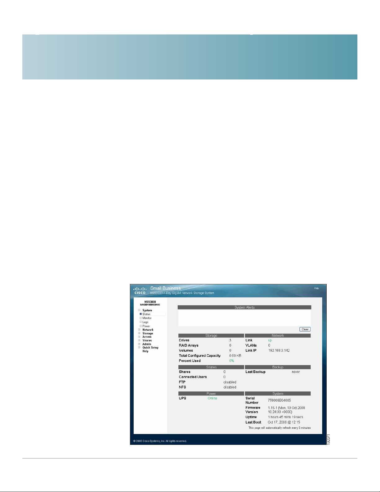
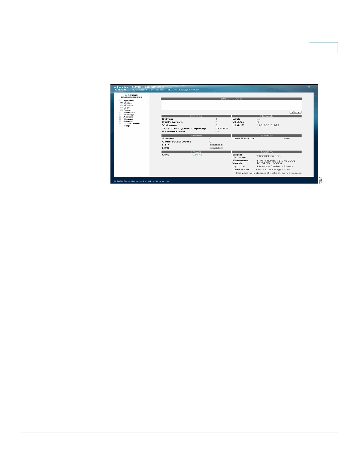
The System Status page provides an overview of the current operating condition
of the NSS. For example, you can view system alert messages such as if a disk
drive is failing or has failed, if a volume is approaching its full capacity, and if an
array rebuild is complete. You can also view the current status of any of the
following: storage, shares, backups, network, power, and system details. Status
pages like the System Status page automatically refresh on a regular interval and
are helpful for monitoring the progress of certain processes such as building
a RAID.
2
Cisco Small Business NSS3000 Series Network Storage System Administration Guide 5
Page 14

Managing the System
System Alerts
System Alerts
2
The following sections describe the information that appears on the System
Status page.
The System Alerts section shows any system messages issued since the last
time they were cleared. Messages can range in severity from informational to
immediate action required.
There are three type of alerts that can appear:
• Error: Indicates the most severe types of problems with the NSS. They
require immediate action. For example, if a disk drive or RAID array is in a
failed condition.
Storage Status
• Warning: Indicates that there is a problem with the NSS that requires
eventual action. For example, if the amount of storage used for a volume is
over 90%.
• Notification: These types of messages are simply to advise of changes to
the NSS. For example, the RAID rebuild is complete.
The Storage area displays details about the configured storage on the NSS,
including:
• Drives: The number of physical disk drives installed.
• RAID Arrays: The number of configured RAID arrays.
• Volume s : The number of configured volumes.
• Total Configured Capacity: The total aggregate size of all configured
volumes.
• Percent Used: The total amount of the configured capacity used.
Cisco Small Business NSS3000 Series Network Storage System Administration Guide 6
Page 15

Managing the System
Network Status
Network Status
The Network area displays the following:
Shares Status
2
• Link: The current status of the Ethernet link. The only status that is visible is
if the link is up. If the link is down, you cannot access the Configuration
Manager.
• VLANs: The number of VLANs configured on the NSS.
• Link IP: The IP address of the Ethernet link.
Backup Status
The Shares area displays status for the following:
• Shares: The number of configured shares.
• Connected Users: The total number of user sessions currently connected
to the NSS.
• FTP: The FTP access state (enabled or disabled).
• NFS: The NFS access state (enabled or disabled).
The Backup area displays the following:
• Last Backup: The date and time of the last backup run. If a backup has
never been run on the system, the word "never" appears.
Cisco Small Business NSS3000 Series Network Storage System Administration Guide 7
Page 16

Managing the System
Power Status
Power Status
2
The Power area displays the following:
• UPS: The following options are available depending on the current
operating condition of the UPS. For more information about the functioning
of the UPS, refer to the UPS documentation.
- Disabled: A UPS is not currently connected to the NSS or is not enabled.
- Online: A UPS is connected to the NSS and is enabled. The NSS is
deriving power from the mains power.
- On Battery (%): The NSS is currently deriving its power from the UPS
battery. The percentage of power still available is also listed.
System Status
The System area displays the following:
• Serial Number: The serial number of the NSS.
• Firmware Version: The current version and date of the firmware installed on
the NSS.
• Uptime: The number of days the NSS has been running since it was last
rebooted.
• Last Boot: The date when the NSS was last rebooted.
Cisco Small Business NSS3000 Series Network Storage System Administration Guide 8
Page 17
Managing the System
Viewing the Hardware Monitor
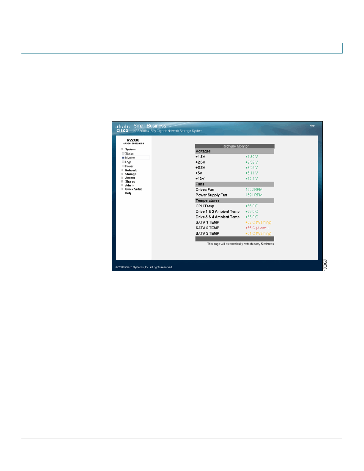
Viewing the Hardware Monitor
The Hardware Monitor page displays details about the following physical
conditions related to the NSS:
2
• Voltages: The current voltage reading for all voltage rails in the system. The
reading is color-coded depending on if the voltage level is within
specification (green) or out of specification and in need of attention (red).
• Fans: The fan speed for each chassis fan. If the fan has stalled, the reading
is color-coded red. Normal fan operation is color-coded green.
• Te mp e ra tu re s : The NSS has temperature sensors located at various parts
of the chassis. Temperature readings are done from these sensors as well
as from any installed disks (if the disk has an internal temperature sensor).
- If a disk does not have a temperature sensor, the reading appears as
"unavailable".
- If the temperature of the system or disks is over or under the ideal
temperature, the temperature is color-coded red. When the temperature
is within the normal range the color-coding is green.
Cisco Small Business NSS3000 Series Network Storage System Administration Guide 9
Page 18
Managing the System
Viewing and Managing the System Logs
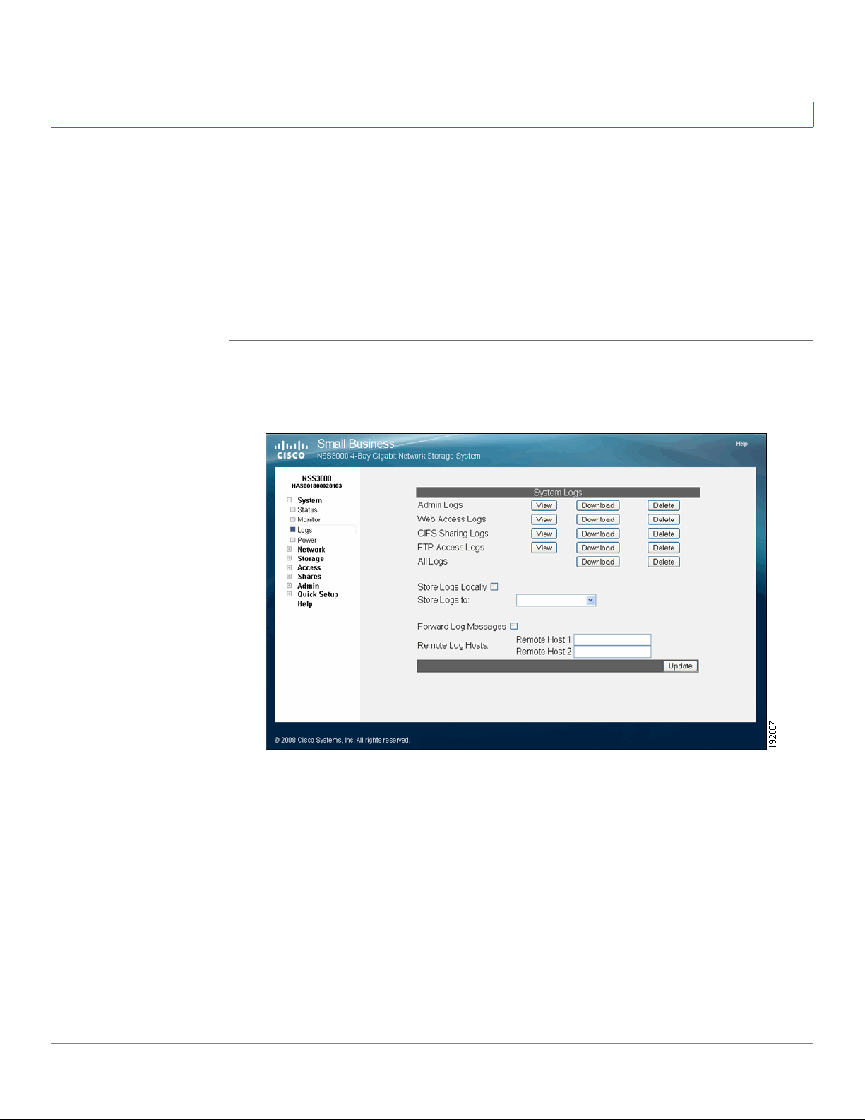
Viewing and Managing the System Logs
The NSS captures various types of information into log files, such as user access
details. You can store the logs locally or on a remote server on the network. Since
local space allocated for log files is limited, the logs are overwritten once the
space is filled.
To work with the log files:
STEP 1 From the Manager Menu, click System Logs.
The System Logs page appears.
2
You can view, download, or delete these types of log files:
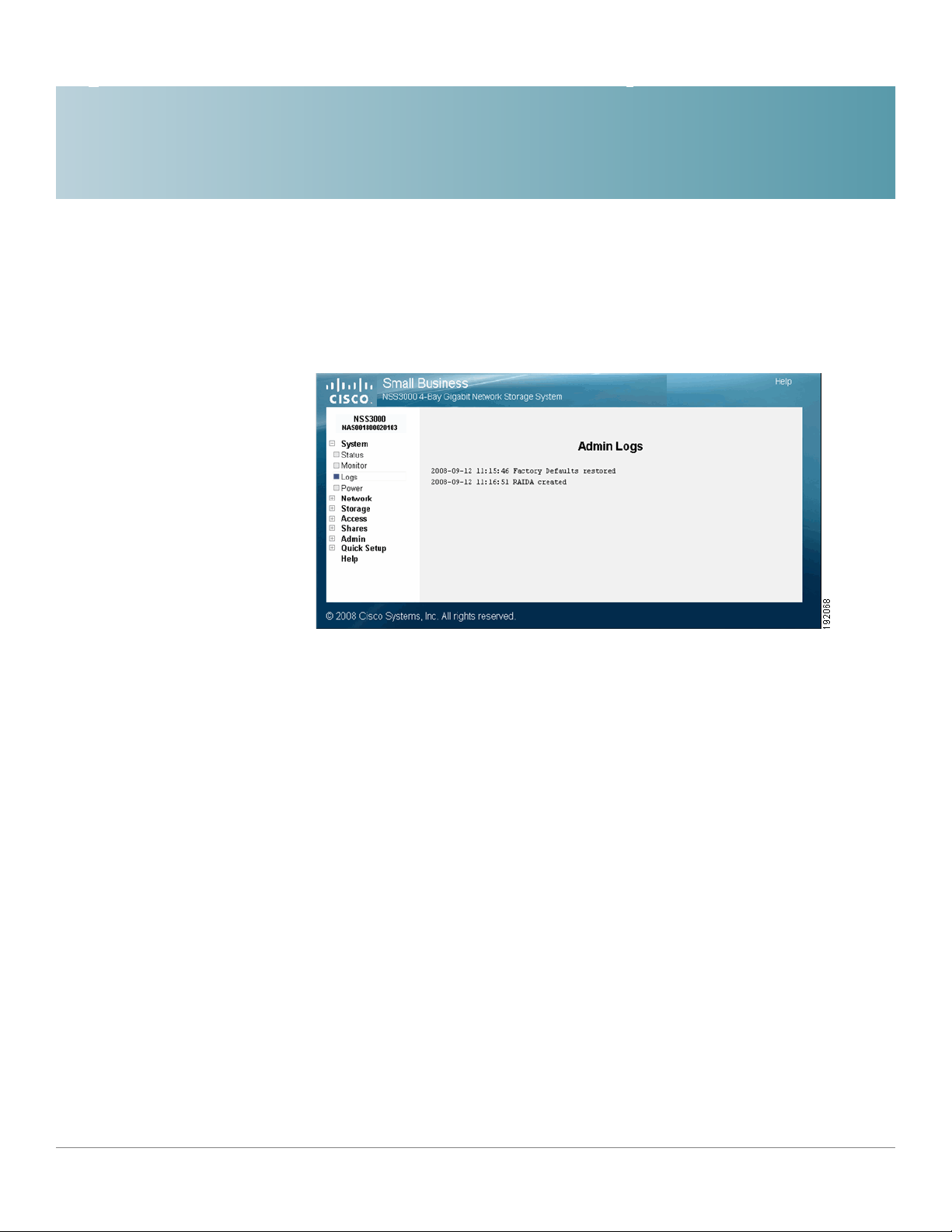
• Admin: A full list of time-stamped actions that were initiated through the
NSS configuration interface.
• Web Access: This log displays IP addresses of the systems that accessed
the NSS configuration interface and the date and time of the authentication
requests. This information helps you detect unauthorized attempts to
access the NSS configuration interface.
• CIFS Sharing: A time-stamped event log of events initiated by users
accessing shares through CIFS.
Cisco Small Business NSS3000 Series Network Storage System Administration Guide 10
Page 19
2
• FTP Access: A time-stamped log of FTP actions, including user logins, file
transfers, and user logouts.
• All Logs: A list of all the log files. You can download and save this file.
This is an example of the Administrator Log window:
STEP 2 Choose where you want to store the log files:
• Locally: To store the log files on the NSS, select Store Logs Locally, and
then select the volume to which you want to store the logs from the options
in the Store Logs to drop-down menu.
• Remotely: To store the log files on a remote server, select Forward Log
Messages, and then enter the hostname or IP address of the server in one
or both of the Remote Log Host fields. (If you set up two remote hosts, the
log file is sent to both servers.) Note that the remote server must be running
a syslog server.
STEP 3 Click Update.
Cisco Small Business NSS3000 Series Network Storage System Administration Guide 11
Page 20
Managing the System
Configuring the System for UPS Support
Configuring the System for UPS Support
You can set up the NSS to use an uninterruptible power supply (UPS) if one is
connected directly to the UPS port on the NSS. The Power Status page provides
an overview of the current power condition of the NSS.
NOTE When the UPS power goes to low battery, a signal is sent through the USB port on
the NSS and a shutdown of the NSS is initiated. Make sure that the UPS has enough
reserve power to sustain the NSS through the shutdown (approximately 5 minutes)
The Power area displays the following:
• AC Status: The following options are available depending on the current
operating condition of the UPS. For more information about the functioning
of the UPS, refer to the UPS documentation.
2
• Disconnected: A UPS is not currently connected to the NSS or has not yet
been enabled.
• Online: A UPS is connected to the NSS and is enabled. The NSS is deriving
power from the mains power.
• On Battery: The NSS is currently deriving its power from the UPS battery.
• Battery Status: The percentage of power still available is also listed and is
color-coded according to the amount of battery remaining.
To enable the UPS:
STEP 1 From the Manager Menu, click System Power.
Cisco Small Business NSS3000 Series Network Storage System Administration Guide 12
Page 21
Managing the System
NSS-Supported UPS Product Families
The System Power page appears.
2
STEP 2 Select Enable UPS support.
STEP 3 Click Update.
NSS-Supported UPS Product Families
The NSS supports these UPS product families:
• APC Back-UPS Pro USB
• APC Back-UPS RS USB
• APC Back-UPS USB
• APC Back-UPS LS USB
• APC Back-UPS ES/CyberFort 350
• APC Smart-UPS USB
Cisco Small Business NSS3000 Series Network Storage System Administration Guide 13
Page 22
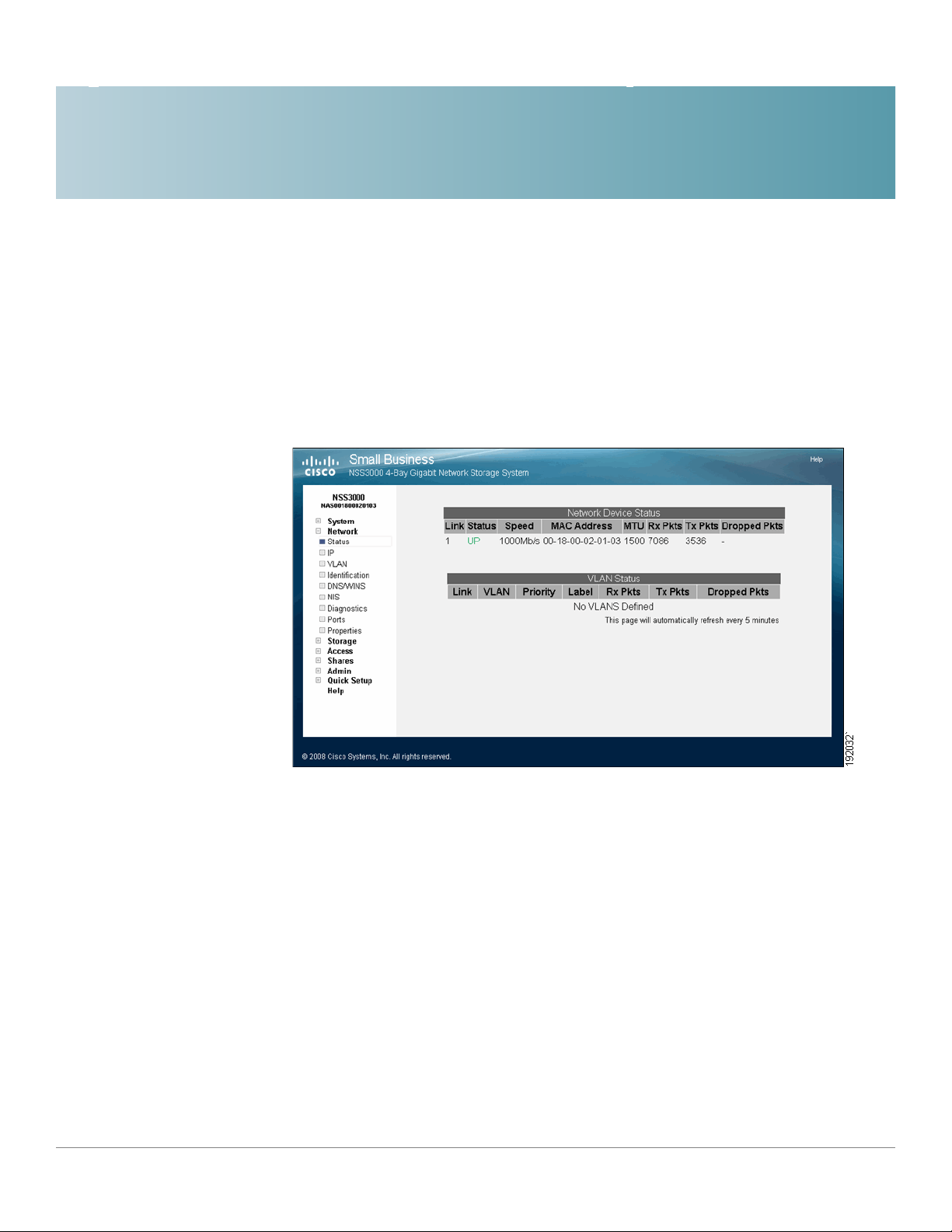
Adding the NSS to your Network
The Network Device Status page displays the current status of the NSS physical
and virtual network interfaces.
3
Physical Interfaces
The Network Device Status table displays the current status of the physical
Ethernet link connected to the NSS.
• Link: The number of the physical link attached to the NSS. The number
appears as 1.
• Status: The status of the physical link.
• Dropped Pkts: The total number of IP packets dropped on the VLAN
interface since the last boot.
Cisco Small Business NSS3000 Series Network Storage System Administration Guide 14
Page 23

Adding the NSS to your Network
Virtual Interfaces
• Status: The status of the physical link. Options include:
- Up: The link is up (color-coded green) and is operational.
- Down: The link is down (color-coded red) and not operational. If a cable
• Speed: The configured speed, in Mbps, of the physical link. Options include:
10 Mbps, 100 Mbps, 1000 Mbps.
• MAC Address: The Ethernet MAC address for the link.
3
is connected to the Ethernet port, check the cable integrity and the
status of the device (switch, router, or computer) at the other end of the
cable. You can use the NSS cable diagnostic feature to assist you. See
”Running Diagnostics of your Physical Link from the Configuration
Interface” on page 32.
If the link is down, this status is not visible since you cannot access the
Configuration Manager.
• MTU: The Maximum Transmission Unit (MTU) in bytes defined for the link.
• Rx Pkts: The total number of IP packets received since the last boot.
• Tx Pkts: The total number of IP packets transmitted since the last boot.
• Dropped Pkts: The total number of IP packets dropped since the last boot.
Virtual Interfaces
The VLAN Status area of the Network Status page displays the current status
and details regarding each configured VLAN.
• Link: The number that appears in this column identifies the physical link on
• VLAN: The VLAN number.
• Priority: The 802.1p priority set for the VLAN. Options include 0 through 7
This is set either manually from the Network Properties page or via the
DHCP server.
which the VLAN is configured.
(0 being best effort data and 7 being network critical data).
• Label: The text description defined for the VLAN.
• Rx Pkts: The total number of IP packets received on the VLAN interface
since the last boot.
Cisco Small Business NSS3000 Series Network Storage System Administration Guide 15
Page 24
Adding the NSS to your Network
Viewing the Network IP Settings.
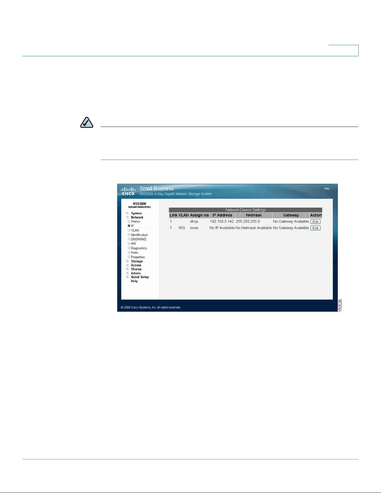
Viewing the Network IP Settings.
The Network Device IP page displays information about the physical and virtual
interfaces currently configured on the NSS.
NOTE If you hotplug the Ethernet link after the initial installation of the NSS, make sure that
you wait 15 seconds between the time you unplug the cable and then plug it back
in. The NSS displays the correct new settings within 10 seconds.
3
To display the Network Device IP page, from the Manager Menu, click
Network
IP. The Network Device Settings table displays the following:
• Link: The number of the physical link attached to the NSS. It appears as 1.
• VLAN: The ID assigned to the virtual interface. For physical interfaces, this
column is blank.
• Assign via: The method used to assign an IP configuration to the physical or
virtual interface. Options include:
- DHCP: The IP configuration was assigned by a DHCP server. Or, if the
interface was configured to use DHCP for IP configuration but no DHCP
server was found, the IP address was assigned by the AutoIP protocol.
Cisco Small Business NSS3000 Series Network Storage System Administration Guide 16
Page 25
Adding the NSS to your Network
Configuring the Network Link IP
- Static: A static IP configuration was manually entered through the NSS
configuration interface.
• IP Address: The IP address for the physical or virtual interface.
• Netmask: The netmask for the physical or virtual interface.
• Gateway: The address of the gateway for the physical or virtual interface.
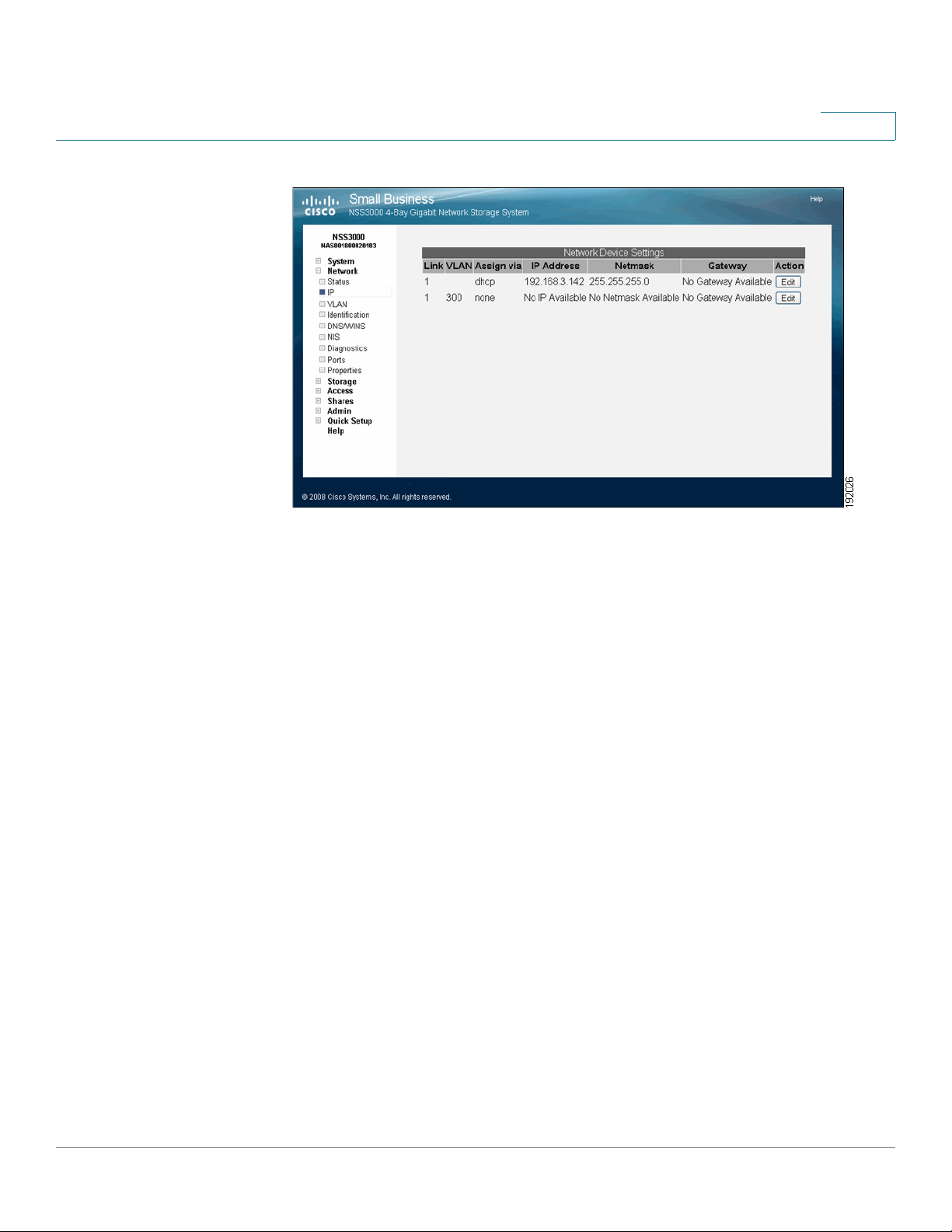
Configuring the Network Link IP
You must configure the method for assigning an IP configuration to each interface
connected to the NSS.
3
NOTE If you hotplug the Ethernet link after the initial installation of the NSS, make sure that
you wait 15 seconds between the time you unplug the cable and then plug it back
in. The NSS displays the correct new settings within 10 seconds.
To set the IP address allocation method for an interface:
STEP 1 From the Manager Menu, click Network IP.
The Network IP page appears listing each interface.
STEP 2 Click Edit on the row of the interface you want to configure.
Cisco Small Business NSS3000 Series Network Storage System Administration Guide 17
Page 26

Adding the NSS to your Network
Resetting the DHCP Lease on a Link
The Network Link Configuration page appears.
3
STEP 3 Select one of the following:
• Obtain IP Address Automatically: Use a DHCP server to retrieve the IP
address, netmask, and gateway address for the interface.
• Use the Following IP Address: Enter the IP configuration details manually
for the IP address, netmask, and gateway, in dotted-quad notation (i.e., set of
four digits separated by periods where each digit is in the range
of 0-255.
STEP 4 Click Update.
Resetting the DHCP Lease on a Link
You can force a renewal of the DHCP lease on the physical link or VLAN that is
configured for DHCP:
STEP 1 From the Manager Menu, click Network IP.
The Network IP page appears listing each physical and virtual interface.
STEP 2 Click Edit on the row of the link IP you want to reset.
The Network Link Configuration page appears.
Cisco Small Business NSS3000 Series Network Storage System Administration Guide 18
Page 27
Adding the NSS to your Network
Viewing VLANs Configured on the NSS
3
STEP 4 Click Update.
Viewing VLANs Configured on the NSS
When you first display the Network VLAN page, the currently configured VLANs
appear. Configuring a VLAN to connect to the NSS depends if it is trunk-based or
port-based.
• To configure a trunk-based VLAN, follow the steps to allow a VLAN to
access the NSS. See ”Allowing a VLAN Access to the NSS” on page 21.
• To configure a port-based VLAN, configure the switch to assign the port to
which the NSS is connected to the desired VLAN. In this case, no NSS
configuration changes are required.
Cisco Small Business NSS3000 Series Network Storage System Administration Guide 19
Page 28
Adding the NSS to your Network
Viewing VLANs Configured on the NSS
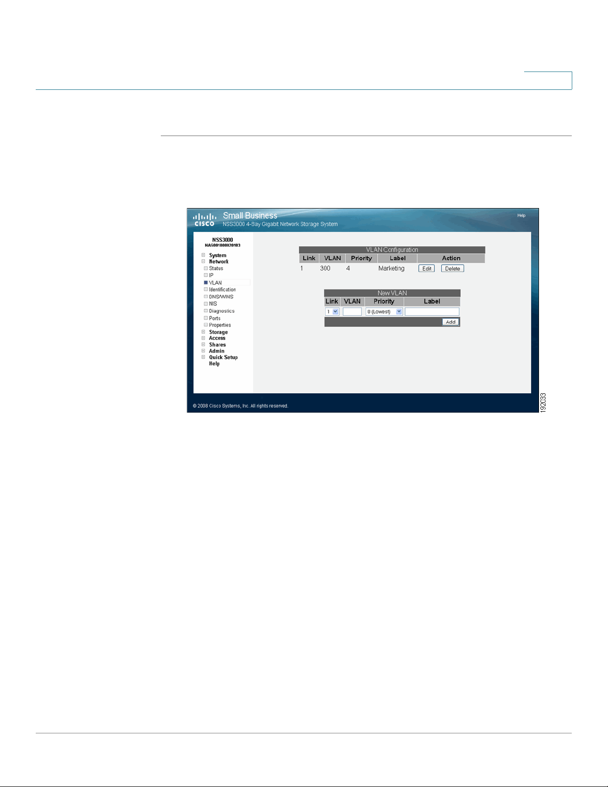
To view the VLANs currently configured on the NSS:
STEP 1 From the Manager Menu, click Network VLAN.
The VLAN Configuration page appears.
3
STEP 2 View the following details for each existing VLAN that appears in the VLAN
Configuration table:
• Link: The physical link attached to the NSS. The number appears as 1.
• VLAN: The ID of the VLAN. This is configured when the VLAN is added to
the NSS and should match the ID of the VLAN as it is configured in your
network. The range of valid VLAN IDs is from 1 to 4095.
• Priority: The quality of service (QoS) as defined in the IEEE 802.1p standard
for the VLAN traffic. VLAN Ethernet frames contain a three-bit priority tag
ranging from 0 to 7 (where 0 is best effort and 7 is network-critical traffic).
• Label: A text description for the VLAN (for example, "Data," "Voice," "Video,"
and so on). This description is used solely as a reference within the NSS
interface and does not affect its operation.
Cisco Small Business NSS3000 Series Network Storage System Administration Guide 20
Page 29
Adding the NSS to your Network
Allowing a VLAN Access to the NSS
Allowing a VLAN Access to the NSS
Configuring a VLAN to connect to the NSS depends if it is trunk-based or portbased. To configure a trunk-based VLAN, follow the steps in this section. To
configure a port-based VLAN, configure the switch to assign the port to which the
NSS is connected to the desired VLAN. In this case, no NSS configuration changes
are required.
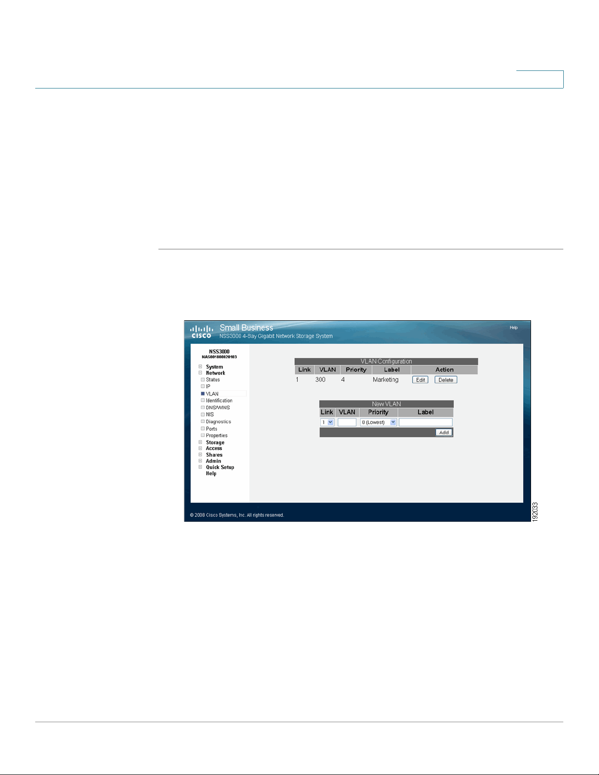
To set up a network VLAN to access the NSS:
STEP 1 From the Manager Menu, click Network VLAN.
The VLAN Configuration page appears.
3
STEP 2 Under New VLAN, configure the following fields:
• Link: This shows as "1" for the Ethernet link.
• VLAN: Enter the ID of the VLAN as it is defined within your network. The
range of valid VLAN IDs is from 1 to 4095.
• Priority: Select the QoS priority for the VLAN traffic as it is defined for your
network. Valid options range from 0 to 7 (as defined by the IEEE 802.1p
standard). VLAN Ethernet frames contain a three-bit priority tag ranging
from 0 to 7 (where 0 is best effort and 7 is network-critical traffic).
Cisco Small Business NSS3000 Series Network Storage System Administration Guide 21
Page 30

Adding the NSS to your Network
Allowing a VLAN Access to the NSS
• Label: Enter a text description for the VLAN (for example, "Data", "Voice",
"Video", etc.). It can be made up of alphanumeric characters. Note that this
description is used solely as a reference within the NSS interface and does
not affect its operation.
STEP 3 Click Add.
The newly added VLAN appears in the VLAN Configuration table. A message
appears to advise that the VLAN does not take effect until you configure the IP
address.
STEP 4 Click OK.
The Network IP page appears. The newly added VLAN appears in the list.
STEP 5 Click Edit for the VLAN you need to configure.
The Network Configuration page appears.
3
STEP 6 Click one of the following, depending on how you want to assign the VLAN IP
addressing:
• Obtain IP Address Automatically: Use a DHCP server to retrieve the IP
address, netmask address, and gateway address for the VLAN.
• Use the Following IP address: Enter the IP configuration details manually.
STEP 7 Click Update.
Cisco Small Business NSS3000 Series Network Storage System Administration Guide 22
Page 31

Adding the NSS to your Network
Changing a VLAN Configuration
Changing a VLAN Configuration
After you set up a VLAN to access the NSS, you can change its configuration
details.
To edit a VLAN configuration:
STEP 1 From the Manager Menu, click Network VLAN.
The VLAN Configuration page appears.
3
STEP 2 Click Edit for the VLAN you want to change.
Cisco Small Business NSS3000 Series Network Storage System Administration Guide 23
Page 32

Adding the NSS to your Network
Removing a VLAN’s Access to the NSS
The Edit VLAN page appears.
3
STEP 3 Make changes to any of the VLAN configuration fields as required.
STEP 4 Click Update.
Removing a VLAN’s Access to the NSS
All connected VLANs appear when you first display the VLAN Configuration page.
You can delete the connection between a VLAN and the NSS. Note that deleting
the VLAN only affects the VLAN’s ability to access the NSS. It does not impact the
VLANs operation within your network.
To disconnect a VLAN’s access to the NSS:
STEP 1 From the Manager Menu, click Network VLAN.
Cisco Small Business NSS3000 Series Network Storage System Administration Guide 24
Page 33

Adding the NSS to your Network
Configuring the NSS Network Identification
The VLAN Configuration page appears.
3
STEP 2 From the VLAN Configuration table, click Delete for the VLAN you want to
remove.
The VLAN disappears from the VLAN Configuration table and can no longer
access the NSS.
Configuring the NSS Network Identification
The Network Identification page is where you configure the network identity of
the NSS, including the hostname and domain membership.
Before you join the NSS to an NTv4 or Active Directory Service (ADS) domain, do
the following:
• Configure the IP and DNS information.
• Configure the NTP Server to synchronizing with ADS server.
• Set up your user and group ID ranges on the User/Group Settings page
(from the Manager Menu, click Access and then Options). If you make a
change to the range after the you join the domain, you must rejoin the NSS
to the domain after the change is made.
Cisco Small Business NSS3000 Series Network Storage System Administration Guide 25
Page 34

Adding the NSS to your Network
!
Configuring the NSS Network Identification
• Set up the Home Directory Location on the User/Group Settings page.
This is used for both domain users and local users.
To configure the NSS network identity:
STEP 1 From the Manager Menu, click Network Identification.
The Network Identification page appears.
3
STEP 2 In the Hostname field, enter the name you want to use for the NSS. Note any
special naming restrictions or conventions enforced by the domain(s) into which
the NSS is being joined.
CAUTION If you change the hostname, any current CIFS connections to shares on the NSS are
disconnected.
STEP 3 To assign the hostname for the NSS using the DHCP server, select Assign
automatically via DHCP. If the DHCP ser ver is not available or if it is not configured
Cisco Small Business NSS3000 Series Network Storage System Administration Guide 26
Page 35

Adding the NSS to your Network
Configuring the NSS Network Identification
to supply a hostname, the NSS hostname is assigned using the information
entered in the Hostname field.
STEP 4 In the Description field, enter the textual description for the NSS as you want it to
appear in the file manager window for your users.
STEP 5 Select the type of network into which you are making the NSS a member from the
these options:
• Workgroup: Make the NSS part of a peer-to-peer network.
• NTv4 Domain: Make the NSS a part of a pre-Windows 2000 domain. If you
select this option, set up the following fields:
- NTv4 Domain: Enter the domain name.
- Domain Controller: Enter the hostname or IP address of the domain
controller.
3
- Username: Enter the username of an account that has administrator
privileges for this domain. Note: The username cannot contain the "%"
character.
- Password: Enter the password for the administrator account. This
password is cleared each time you click Update. You must re-enter the
password each time you edit the fields on this page to ensure the rejoin
of the domain is successful.
• Member of Active Directory domain: Make the NSS part of an Active
Directory (ADS) domain. If you select this option, set up the following fields:
- Active Directory Domain: Enter the domain name. Note that you might
have to use the DNS fully qualified domain name. For example,
"domain.com" versus just "domain."
- Kerberos Realm: Enter the name of your Kerberos realm. If you are not
sure what to enter here, enter the domain name. In most standard
Windows domain installations, this is the correct value. Note that you
might have to use the fully qualified domain name for the Kerberos
Realm fields. For example, "domain.com" versus just "domain".
- Domain Controller: Enter the hostname or IP address of the domain
controller.
- Username: Enter the username of an account that has administrator
privileges for this domain. Note: The username cannot contain the
"%" character.
Cisco Small Business NSS3000 Series Network Storage System Administration Guide 27
Page 36

Adding the NSS to your Network
Configuring the NSS Network Identification
- Password: Enter the password for the administrator account. This
password is cleared each time you click Update. You must re-enter the
domain password each time you edit fields on this page to ensure the
rejoin of the domain is successful.
- Enable Support for Large ADS Domains: Check this option to connect
the NSS to an ADS domain that has more than 1000 users and groups.
((This is the sum of the individual users and individual groups.).
It can take up to 5 minutes to complete the domain join for large ADS
domains. When the NSS initially joins the domain, there might be a delay
of several minutes until the domain users and groups appear in the user
interface. This delay only occurs after the join. Any changes that you
make to the users and groups on the domain controller (additions or
deletions) can take up to one hour to appear in the user interface.
3
NOTE The NSS3000 supports ADS domains of up to 8,000 users and
- System Volume Location: If you checked the Enable Support for Large
ADS Domains field, you must then select the RAID array on which to
store the system cache files associated with the ADS domain join. The
RAID array that you choose must have at least 512 MB of available
space. Note that If you delete the RAID array on which the system
volume is located, leave the domain by switching to workgroup mode,
and then delete the RAID array.
STEP 6 Click Update.
If you configured the NSS to join a domain, when you click Update, the domain
join occurs. The NSS configuration interface displays the status of the domain
join (successful or not successful).
NOTE If you are joined to a domain and make changes to the fields on this page,
make sure that you re-enter the domain password as the NSS automatically
rejoins the domain when you click Update.
groups. If you connect the NSS to an ADS domain larger than this, you
might have problems making CIFS connections to the NSS.
Cisco Small Business NSS3000 Series Network Storage System Administration Guide 28
Page 37

Adding the NSS to your Network
Configuring DNS or WINS for Name Resolution
Configuring DNS or WINS for Name Resolution
Within a network, DNS and WINS are used to translate hostnames into IP
addresses. For example, the hostname "myserver" might translate to 172.1.135.6.
Configuring how the NSS works with name resolution depends on what type of
servers exist within your network.
To configure the DNS or WINS server addresses for your network:
STEP 1 From the Manager Menu, click Network DNS/WINS.
The Network Name Resolution page appears.
3
STEP 2 Based on your network setup, configure the following fields:
• Search Domain: Enter the address of the DNS search domain accessible
by the NSS. For example, "mycompany.com".
• Primary DNS Server: Enter the IP address of the primary DNS server on
your network.
• Alternate DNS Server: Enter the IP address of a second DNS server to be
used should the primary DNS server become unavailable. This field
is optional.
• Assign automatically via DHCP: Select this to assign the IP address for the
DNS server using the DHCP server. If the DHCP server cannot be found or
Cisco Small Business NSS3000 Series Network Storage System Administration Guide 29
Page 38

Adding the NSS to your Network
Joining the NSS to a Network Information System (NIS) Domain
times out, the DNS server IP address is assigned the IP address manually
entered in the Primary or Alternate DNS Server fields.
• Primary WINS server: If your network has a WINS server, enter its address
or hostname. This field is optional.
• Alternate WINS server: If your network has a secondary WINS server,
enter its address or hostname. This field is optional.
• Assign automatically via DHCP: Select this to assign the IP address or
hostname for the WINS server using the DHCP server
If the DHCP server cannot be found or times out, the DNS server IP address
is assigned the IP address manually entered in the Primary or Alternate
WINS Server fields.
STEP 3 Click Update.
3
Joining the NSS to a Network Information System (NIS)
Domain
To join the NSS to a NIS domain, you need to configure and enable it.
NOTE Before you join a NIS domain, make sure that you set up or make changes to the NIS
domain users and groups ID range on the User/Groups Settings page. This
minimizes the risk of collisions of user or group IDs within your network.
To configure the NSS for NIS:
STEP 1 From the Manager Menu, click Network NIS.
Cisco Small Business NSS3000 Series Network Storage System Administration Guide 30
Page 39

Adding the NSS to your Network
Joining the NSS to a Network Information System (NIS) Domain
The NIS Configuration page appears.
3
STEP 2 Select Enable NIS.
STEP 3 Enter the NIS domain name in the NIS Domain Name field.
STEP 4 Set the bind state by clicking one of the following:
• Broadcast for NIS Server: Click this option to have the NSS search until it
finds the NIS server on the network.
• Use the following NIS Servers: To manually identify the NIS server you
want the NSS to use, click this option, and then enter the address of up to
three different NIS servers.
The Bind State field shows the current bind status of the NSS. Options include:
"Invalid" (the NSS is not joined to an NIS domain), or "Enabled" (the NSS is
successfully joined to a NIS domain).
STEP 5 Click Update.
Cisco Small Business NSS3000 Series Network Storage System Administration Guide 31
Page 40

Adding the NSS to your Network
Editing Access Control Lists (ACLs) from Windows Explorer: Restrictions
3
Editing Access Control Lists (ACLs) from Windows Explorer:
Restrictions
Access Control Lists (ACLs) are used to set user and group access privileges for
specific files and folders stored on the NSS. There are certain restrictions to be
aware of as you work with ACLs through Windows Explorer:
• Group versus User ACLs: You can only set up an ACL for individual users.
You cannot set up a group ACL.
• NIS domain: You cannot create or edit ACLs for NIS domain users; they do
not appear in the Security tab in Windows Explorer.
Running Diagnostics of your Physical Link from the Configuration Interface
The NSS lets you test the physical network cable attached to the Ethernet link for
certain fault conditions. You can either run the test through the Configuration
Interface or from the LCD panel on the front of the chassis. The test automatically
runs each time you display the Network Diagnostics page or when you display the
Ethernet Cable screen from the LCD. Running this test does not affect the use of
the link in any way.
NOTE The diagnostics test is only supported when the NSS is connected to a Gigabit
Ethernet switch.
To test the physical link from the Configuration Interface:
STEP 1 From the Manager Menu, click Network Diagnostics.
The Network Diagnostics page appears.
Cisco Small Business NSS3000 Series Network Storage System Administration Guide 32
Page 41

Adding the NSS to your Network
Running Cable Diagnostics from the LCD
3
STEP 2 View the Link Status area for the test result or view the Ethernet Cable screen
from the LCD panel. If the link is down, you cannot access the
Configuration Manager.
Running Cable Diagnostics from the LCD
To test the physical link from the LCD:
STEP 1 Press and hold down the Display button on the front of the chassis until the
Ethernet Cable screen appears.
STEP 2 If the link is up, the panel displays the status of the cable. If the link is down, after a
few seconds the test starts.
After the test completes, the status of the cable appears. If the link is up, the
status appears as OK. If there is a problem with the link, the status is reported
according to the pairs within the cable.
These are the possible test results (because of screen space limitations, each
page shows two sets of cable pairs):
• Short: If the pair has a short, the message appears as "pair a-b short@ Xm"
(where "a" and "b" are the numbers of the pair, "X" is the location in the cable
where the short was found, and "m" stands for metres).
Cisco Small Business NSS3000 Series Network Storage System Administration Guide 33
Page 42

Adding the NSS to your Network
Configuring the Network Ports
• Open: If the cable has an open, the message appears as "pair a-b open@
Xm (where "a" and "b" are the numbers of the pair, "X" is the location in the
cable where the open was found, and "m" stands for meters).
• Disconnected: If the cable shows an open at the minimum measurable
distance, it is assumed that the cable is not connected. The message "Cable
is not connected" appears.
The cable diagnostic test only runs the first time you display the Cable
Diagnostics screen. To rerun the test, scroll through the LCD pages until you
redisplay the Cable Diagnostics screen.
Configuring the Network Ports
By default the NSS runs network services on their well known (IETF defined) port
numbers. You can change the port on which any particular service runs. When you
disable WAN access for a given service, only hosts on the same subnet as the
NSS may connect to that service. This is a shortcut to manually defining an
equivalent network filter.
3
To set up the network services:
STEP 1 From the Manager Menu, click Network Ports.
Cisco Small Business NSS3000 Series Network Storage System Administration Guide 34
Page 43

Adding the NSS to your Network
Setting up the Ethernet Frame Size & Advertising Modes
The Network Ports Configuration page appears.
3
STEP 2 Change the port assignment for any of the following service types:
• FTP/FTPS Port: The well-known port setting is 21. Select Disable WAN
Access to disallow FTP and FTPS protocol access to the NSS from a WAN.
• Web Server Port: The well-known port setting is 80.
To access the NSS configuration interface, you must have either the HTTP
port or HTTPS port enabled. Select Disable WAN Access to disallow HTTP
protocol access to the NSS from a WAN.
• SSL Web Server Port: The well-known port setting is 443. Select Disable
WAN Access to disallow HTTPS protocol access to the NSS from a WAN.
STEP 3 Click Update.
Setting up the Ethernet Frame Size & Advertising Modes
The Network Properties page lets you set the Ethernet frame size and determine
how you want to advertise the presence of the NSS within your network.
Cisco Small Business NSS3000 Series Network Storage System Administration Guide 35
Page 44

Adding the NSS to your Network
Setting up the Ethernet Frame Size & Advertising Modes
To configure the network properties:
STEP 1 From the Manager Menu, click Network Properties.
The Network Properties page appears.
3
STEP 2 Set the Maximum Transmission Unit (MTU), in bytes, in the MTU field. This is the
largest Ethernet frame that your network can handle. The default MTU size is 1500
bytes. MTU sizes greater than 1500 bytes are considered "jumbo frames".
STEP 3 To assign the link MTU size automatically using the DHCP server, click Assign
automatically via DHCP. In this case, the value entered in the MTU field is used as
a backup if the DHCP server does not provide an MTU value or if the server cannot
be reached.
STEP 4 Based on your network requirements, enable any of the following:
• Advertise using UPnP: The NSS is advertised within the network
using UPnP.
• Advertise using Zeroconf/Bonjour: The NSS is advertised within the
network using Zeroconf/Bonjour.
STEP 5 Click Update.
Cisco Small Business NSS3000 Series Network Storage System Administration Guide 36
Page 45

Configuring your Storage
The Storage Status page shows the current state of the disk drives, arrays, and
volumes currently installed or exported to the NSS. You can also view the
S.M.A.R.T. health report for each physical disk. To display the Storage Status
page, from the Manager Menu, click Storage
Storage Status page automatically refresh on a regular interval and are helpful for
monitoring the progress of certain processes such as checking the condition of a
drive.
The LCD on the front of the chassis also lets you view the state of the RAID arrays
and volumes.
4
Status. Status pages like the
Cisco Small Business NSS3000 Series Network Storage System Administration Guide 1
Page 46

Configuring your Storage
Storage Status Tables
Storage Status Tables
The Storage Status page include the following tables:
Disk Status Table
The Disk Status table lists each of the physical disks installed in the NSS. The
table is made up of the following columns:
• Port: The port number on the NSS in which the disk is installed.
• Model: The model of the disk drive. This information is read from the disk
drive.
• Size: The size of the disk drive.
4
• Health: The system monitors each disk drive and reports the condition of
the disk drive. Options include:
- Passed: The disk drive has passed the S.M.A.R.T. test and is considered
fully operational. The Error LED on the disk drive is off.
- Failing: The disk drive has failed the S.M.A.R.T. test and is predicated to
fail. The red Error LED on the disk drive is blinking.
- Failed: The disk drive is not operational (has failed). The red Error LED on
the disk drive is on solid.
• Status: The state of use for the disk drive. Options include:
- Online: The disk drive is spun up.
- Standby: The disk drive is idle and is spun down.
- Offline: The disk drive is failed.
• Action: There are available action buttons associated with each installed
disk drive:
- Get Details: View the current, detailed S.M.A.R.T. report for the
disk drive.
Cisco Small Business NSS3000 Series Network Storage System Administration Guide 2
Page 47

Configuring your Storage
Storage Status Tables
RAID Arrays Table
The RAID Arrays table lists each array (either RAID or JBOD) currently configured.
It includes the following:
4
• Label: The name assigned to the array.
• RAID Level: The configured RAID level.
• Spare: Indicates if the RAID has a spare or not.
• Size: The size allocated for the array. The amount of available storage for an
array depends on the number of drives in the array, the size of the smallest
drive, as well as the RAID level assigned.
• Status: The current condition of the RAID array. Options include:
- Clean: The array is in a normal state. The status is color-coded green.
- Degraded: For RAID arrays with redundancy (i.e., RAID levels 1, 5, 10),
one or more of the redundant disk drives is removed from the system or
is failed. In this state, the array is fully recoverable. The status is colorcoded orange.
- Failed: One or more disk drives have been removed or are
unrecoverable from a RAID0 or a JBOD array. For RAID levels 1, 5, 10, it
indicates a loss of the redundant disks in the array plus at least one more
drive. In this state, the array is unrecoverable.
- Rebuilding: A RAID level with redundancy is being rebuilt. Note that
during a rebuild, the RAID array is still fully usable. The status is colorcoded orange. During the rebuild, the disk drive LED slowly blinks green.
- Stopped: A RAID array was stopped by the system (through degraded
mode management) due to it being in degraded mode for the amount of
time configured in the Storage Options page. Volumes associated with
a stopped array are unmounted and unusable. To start the RAID array,
click the Start button.
Cisco Small Business NSS3000 Series Network Storage System Administration Guide 3
Page 48

Configuring your Storage
Storage Status Tables
Volumes Table
The Volumes table provides a list of the existing volumes. It includes the following:
4
• Location: The name of the RAID array on which the volume is configured.
• Volume : The name assigned to the volume.
• Tot a l S p ac e : The amount of space configured for the volume.
• Used Space: The amount of space used on the volume.
• Avail. Space: The amount of unused space on the volume.
• % Used: The percentage of available space that is used.
• Encrypted: Whether the volume is encrypted or unencrypted.
• Locked: The encrypted volume is locked and is not accessible. To make the
volume accessible, the volume must be unlocked.
USB Storage Status
If you mount a USB flash device by inserting it into the AUX-1 port on the front of
the chassis, the USB Storage Status table appears. If there is no USB flash device
mounted, the USB Storage Status table does not appear. You can use the USB
flash device to save a backup of the configuration file. When you finish using the
USB flash device, click Unmount before you remove it from the AUX-1 port. (The
AUX-1 LED on the front of the chassis must be off before you can safely remove the
USB flash device.) If you remove the USB flash device in a mounted state, you risk
corrupting the files or filesystem.
The USB Storage Status table provides the following details about the mounted
USB flash device:
• Disk: The type of disk in this case is the USB flash.
• Tot a l S p ac e : The total amount of space (both used and available) on the
USB flash device.
• Used Space: The amount of space taken up on the USB flash device.
• Available Space: The amount of unused space on the USB flash device.
• %Used: The percentage of space used on the USB flash device.
• Action: The Unmount button unmounts the USB flash device so that it can
be safely removed from the AUX-1 port.
Cisco Small Business NSS3000 Series Network Storage System Administration Guide 4
Page 49

Configuring your Storage
Managing RAID Arrays
Managing RAID Arrays
RAID is an acronym for Redundant Array of Inexpensive Disks. In storage
environments, a RAID array uses multiple physical disk drives to create a single
logical unit from which data can be shared or replicated between the drives. A
RAID array also simplifies the data management as the data appears in one logical
unit. Choosing to store your data using a RAID array gives you the benefit of speed
and performance; storage capacity; decreased downtime costs and increased
availability; fault tolerance; and higher data security.
The LCD on the front of the chassis lets you view the RAID level (i.e., JBOD,
0,1,5,10), the state of the RAID (i.e., clean, degraded, rebuild, failed or stopped), and
the percent completion of the RAID rebuild if in progress.
About the RAID Arrays Page
4
The RAID Arrays page is where you manage the local RAID and JBOD arrays. To
display the RAID Arrays page, from the Manager Menu, click Storage
RAID.
Cisco Small Business NSS3000 Series Network Storage System Administration Guide 5
Page 50

Configuring your Storage
Choosing a RAID Array Level
Choosing a RAID Array Level
RAID (Redundant Array of Inexpensive Disks) is a technology that enables multiple
low-cost hard drives to be used together in a way that increases performance
and/or reliability compared to that of a single drive. The component devices in a
RAID array appear as a single logical storage device. There are various types of
RAID, referred to as RAID levels. Some RAID levels increase the performance of
the array, some increase the reliability, and others do a mixture of both. The NSS
supports the following RAID levels: 0, 1, 5 and 10. The NSS also supports JBOD
(Just a Bunch of Disks), which is technically not a RAID level.
These variables are used in the formulas used to calculate the total capacity of
each RAID level:
• m: capacity of the smallest disk in the array
4
• n: number of disks in the array
Stripe (RAID0): RAID0 stripes the data written to the array across the component
disks. The data is broken into chunks and each chunk is written to a different disk.
Reads and writes to each disk occur in parallel, speeding up the total read and
write performance of the array.
• Minimum Number of Disks: 2
• Total capacity: m * n
• Advantages: Increased read and write performance.
• Disadvantages: Decreased reliability. A failure of any component disk in the
array causes the entire array to fail.
Mirror (RAID1): RAID1 writes the same data to each disk in the array. The disks are
referred to as mirrors because each one mirrors the data stored on the others. As
long as one disk in the array is intact, all data can be read back from the array. If a
disk fails in the array and is then replaced, the array must copy the entire contents
of a good disk to the new disk. This process is referred to as resyncing. During a
resync, the array continues to be available for reads and writes. When an array
contains a failed disk, it is operating in degraded mode. This reflects the
decreased performance and reliability of the array when it is missing disks.
• Minimum Number of Disks: 2
• Total capacity: m
• Advantages: Increased reliability. The array can sustain the loss of all but
one disk without any data loss. Each mirror disk added to the array
Cisco Small Business NSS3000 Series Network Storage System Administration Guide 6
Page 51

Configuring your Storage
Choosing a RAID Array Level
Mirror + Spare (RAID1): RAID1 plus a hot spare.
Parity (RAID5): RAID5 stripes data written to the array like RAID0, except that,
unlike RAID0, RAID5 generates parity information that also gets striped across the
array. This parity information is used during the reconstruction of the lost data
when a drive fails in the array.
4
increases the reliability (for example, a two-disk RAID1 is half as likely to fail,
a three-disk RAID1 is one-third as likely to fail, and so on). Increased read
performance.
• Disadvantages: Decreased aggregate storage capacity (each mirror disk
does not contribute to the total capacity of the array). Decreased write
performance. I/O intensive when resyncing mirrors.
• Minimum Number of Disks: 3
• Total capacity: m
• Advantages: The hot spare can be used in case of a failure to either disk in
the mirrored pair.
When a failed disk is then replaced, the array must regenerate and rewrite the
parity information of the array. This process is referred to as “rebuilding”. During a
rebuild, the array continues to be available for reads and writes. If the parity
information in the array gets out of sync with the data in the array, usually as the
result of an unexpected loss of power to the system, the array must be rebuilt. Like
RAID1, if a disk is missing from the array, the array is said to be operating in
“degraded” mode.
• Minimum Number of Disks: 3
• Total capacity: m * (n-1)
• Advantages: Increased reliability. The RAID array can sustain the loss of any
single disk without any data loss. Increased read and write performance.
• Disadvantages: Decreased aggregate storage capacity (you lose the
equivalent capacity of a single disk). CPU intensive calculation of parity,
especially during rebuild operation. I/O intensive during rebuild operation.
Parity + Spare (RAID5): RAID5 with a hot spare.
• Minimum Number of Disks: 4
• Total capacity: m * (n-1)
• Advantages: The hot spare is available in case of a failure of one of the disks
in the array.
Cisco Small Business NSS3000 Series Network Storage System Administration Guide 7
Page 52

Configuring your Storage
Creating a RAID Array
JBOD: JBOD lets you combine multiple disks of mixed capacities into a single
logical storage device. The capacity of the JBOD array is the sum of the total
capacities of the individual component disks (that is, it does not have the limitation
of RAID0 where you lose some capacity when using mixed sized disks). JBOD
offers no performance increase compared to the component disks. It has lower
reliability than the component disks, as the failure of a single disk results, in
general, in the failure of the whole array. Depending on how you create volumes on
the JBOD array, you might be able to recover data when one or more disks in the
JBOD fail. This, however, is not guaranteed.
4
• Minimum Number of Disks: 1
• Total capacity: sum of capacities of component disks.
• Advantages: Maximal storage capacity, especially when using mixed size
disks.
• Disadvantages: Decreased reliability.
Creating a RAID Array
After you install the physical disks, you can create the RAID arrays. Before you
create a RAID array, either for the first time, or when you are rebuilding it as a result
of failed disks in the array, set the rebuild priority to determine how you want to
allocate the system resources for the rebuild. To set the rebuild priority, see
”Storage Options” on page 29.
NOTE When adding disks to an array, we recommend that you use the same model of disk
with the same capacity. With the exception of a JBOD, RAIDs are configured to use
the maximum of the smallest disk capacity in the array for each additional disk in
the array. For example, if you install two, 250 GB disks and one 500 GB disk in a
RAID0 array, the total capacity is only 750 GB.
STEP 1 From the Manager Menu, click Storage RAID.
Cisco Small Business NSS3000 Series Network Storage System Administration Guide 8
Page 53

Configuring your Storage
Creating a RAID Array
The RAID page appears.
4
STEP 2 The available disks appear in the New RAID Device table. Select each disk that
you want to include in the array.
STEP 3 From the RAID Level drop-down menu, click the RAID level of the RAID array that
you want to create.
STEP 4 Click Add.
NOTE Creating a RAID can take some time to complete depending on the disk sizes and
the selected RAID level. You can monitor the progress of the RAID build from the
Storage Status page. When the build finishes, the array appears in the RAID
Arrays table. The disks used in the array are no longer available for creating
additional arrays.
Cisco Small Business NSS3000 Series Network Storage System Administration Guide 9
Page 54

Configuring your Storage
Adding a Disk Drive to an Array
Adding a Disk Drive to an Array
You can add additional disks to an existing RAID1, RAID5, and RAID10 array. As
long as the array is clean, these disks then become spares.
NOTE When adding disks to an array, we recommend that you use the same model of disk
with the same capacity. The new disk must have at least the same capacity of the
smallest disk currently in the array. With the exception of a JBOD, RAIDs are
configured to use the maximum of the smallest disk capacity in the array for each
additional disk in the array. For example, if you install two, 250 GB disks and one 500
GB disk, the total capacity is 750 GB.
To add a disk to an array:
4
STEP 1 If not already installed in the chassis, insert the disk into the NSS.
STEP 2 From the Manager Menu, click Storage RAID.
The RAID page appears.
Cisco Small Business NSS3000 Series Network Storage System Administration Guide 10
Page 55

Configuring your Storage
Deleting an Array
STEP 3 In the RAID Arrays table, click Edit for the applicable RAID array.
4
The RAID Device Configuration page appears.
All available disk drives appear in the listing.
STEP 4 Click Add to add the disk drive to the array.
• If the disk drive is added to a functional array, the disk drive becomes a hot
• If the disk drive is added to a degraded array, the RAID array is rebuilt. While
Deleting an Array
You can remove an existing array and release the disks used in the array back into
available storage. Deleting an array also deletes any existing data on the array
(including the volumes, shares, and quotas). If you delete an array that contains the
volume that is used as the location of your users’ Home Directories, you must
assign a new volume as the Home Directory location.
spare.
the rebuild continues, you can still use the array. After the rebuild process
completes, the disk becomes part of the redundant storage. You can
monitor the progress of the rebuild through the System Status page.
Cisco Small Business NSS3000 Series Network Storage System Administration Guide 11
Page 56

Configuring your Storage
Migrating a RAID Array to another Storage Device
To delete an existing array:
STEP 1 From the Manager Menu, click Storage RAID.
The RAID page appears.
4
STEP 2 Click Delete in the row of the RAID array that you want to delete.
A warning message appears.
STEP 3 To c o n t i n ue , c l ic k OK.
The deleted array disappears from the list of existing arrays. The disks used in the
array are released back into available storage and appear in the New RAID
Device table.
Migrating a RAID Array to another Storage Device
After you build a RAID array, you can migrate it to a different NSS3000 as required
(you cannot migrate a RAID to or from the NSS4000 or NSS6000). If you are
migrating a RAID array from the NSS3000 or to another network NSS3000, make
sure that you power down the RAID array (versus hot-plugging it) before migrating
it into the new system.
Cisco Small Business NSS3000 Series Network Storage System Administration Guide 12
Page 57

Configuring your Storage
Virtualizing Storage within your Network
To migrate a RAID array:
STEP 1 Power down the NSS (from which you are removing the RAID array).
STEP 2 Remove each of the disk drives that make up the RAID array to be moved.
STEP 3 Power down the NSS to which you are migrating the RAID array.
STEP 4 Insert each of the disk drives in the RAID array into the new NSS.
NOTE You can install the drives into the new NSS in any order. You do not need to install
them in the same order or slots that they were installed in the original NSS.
STEP 5 When all the disk drives are installed, power up the NSS.
4
STEP 6 If any local users were assigned permissions to shares on the RAID array, you must
either save the configuration from the original RAID array device and then upload it
to the new NSS, or manually reconfigure the users and their share permissions.
Virtualizing Storage within your Network
NOTE After you configure a virtual RAID, you cannot migrate the disks used for that RAID
to another NSS. You also cannot export storage from a device that uses imported
storage.
Currently Exported Storage
When you display the Storage Virtualization page, the Currently Exported
Storage table appears. It shows the details for any exported disks or arrays:
• Device: The name of the exported disk or array.
• Size: The size of the exported storage.
• Exported As: The serial number of the exported NSS.
Cisco Small Business NSS3000 Series Network Storage System Administration Guide 13
Page 58

Configuring your Storage
!
Exporting Storage to your Network
• Imported by: The serial number of the NSS that has imported the storage. If
the exported disk or array has not yet been imported by the master NSS,
"None" appears in this column.
• Action: Click the Unexport button to stop the NSS from exporting the
associated drive or array. This frees up the drive or array for use in local
RAID arrays.
Exporting Storage to your Network
If you have multiple NSS units in your network, you can easily export the storage to
form a large, logical storage unit that can be managed from the master NSS. The
first step in creating virtualized storage is to export the disk(s) or array to the
network. Note that when you export storage, you need to consider how things like
rebooting an NSS might impact users of the virtualized storage. While the logical
storage is controlled from the master NSS, the physical device (including the disk
drives) is still controlled through the slave’s configuration interface and is affected
by the conditions of the physical unit.
4
CAUTION After you configure a virtual RAID, you cannot migrate the disks used for that RAID
to another NSS. You also cannot export storage from a device that uses imported
storage.
To export storage to the network:
STEP 1 Log into the configuration interface for the device from which you are exporting
storage.
STEP 2 From the Manager Menu, click Storage Virtualization
The Storage Virtualization page appears.
Cisco Small Business NSS3000 Series Network Storage System Administration Guide 14
Page 59

Configuring your Storage
Creating Virtualized Storage
4
STEP 3 From the Export a device area, select each device that you want to export from
the list of available devices.
STEP 4 From the Link field, select the physical link that you want to use to export the
storage.
STEP 5 Click Export.
STEP 6 The selected disk(s) disappear from the available list of arrays and appear in the
Currently Exported Storage table at the top of the page. To use the exported
storage, follow the steps in the next section, Creating Virtualized Storage.
Creating Virtualized Storage
After you export storage from a slave storage unit, it becomes available to other
storage units in your network. The recommended way to use virtualized storage is
to assign a master storage unit (the master must be an NSS6000 series model).
The designated master unit then becomes the configuration point for all your
storage-related management. You can use the exported storage to create a JBOD,
which you can then use to set up volumes and shares.
Keep in mind that although the storage is managed through the master unit, the
physical device that contains the exported storage is still managed through the
applicable slave unit. If you affect the physical disk drives (e.g., shut down the
power to the unit), this affects any logical storage built using those disk drives.
Cisco Small Business NSS3000 Series Network Storage System Administration Guide 15
Page 60

Configuring your Storage
Creating Virtualized Storage
NOTE After you configure a virtual RAID, you cannot migrate the disks used for that RAID
to another NSS. You also cannot export storage from a device that uses imported
storage.
To create a JBOD with exported disks:
STEP 1 Log in to the configuration interface from the master NSS6000 series unit.
STEP 2 From the Manager Menu, click Storage RAID.
4
The RAID page appears.
Exported disks from other NSS units in the network appear in the New RAID
Device table.
STEP 3 From the New RAID Device table, click the disks or arrays that you want to include
in the JBOD.
STEP 4 Select JBOD as the RAID level.
STEP 5 Click Add.
The JBOD appears in the RAID Arrays listing. You can now create volumes
from the virtualized JBOD.
Cisco Small Business NSS3000 Series Network Storage System Administration Guide 16
Page 61

Configuring your Storage
Unexporting Storage
Unexporting Storage
You can choose to unexport pieces of the storage currently exported to the
network.You can only unexport storage that has not yet been used.
To unexport a piece of storage:
STEP 1 From the Master device, delete any RAID arrays associated with the storage you
want to unexport. See ”Deleting an Array” on page 11.
STEP 2 Display the Configuration Interface for the slave device that contains the storage
you want to unexport.
STEP 3 From the Manager Menu, click Storage Virtualization.
The Storage Virtualization page appears.
4
STEP 4 Click Unexport for the device you want to release from the network.
The disk drive(s) or array no longer appears in the Currently Exported Storage
list. It now appears in the Export a device list and is again available for use.
Cisco Small Business NSS3000 Series Network Storage System Administration Guide 17
Page 62

Configuring your Storage
Volume Management
Volume Management
A volume is a way to partition storage space available on an array. The Storage
Volume s page shows the following details about configured volumes or create
additional volumes.
The LCD lets you view the existing volumes and the percentage of space used.
4
The Volumes table displays the following:
• Volume : The name of the volume.
• Location: The array on which the volume is located.
• Tot a l S p ac e : The amount of space allocated for the volume (in MB, GB, or
TB).
• % Used: The amount of space, as a percentage, that is currently used.
• Crypto: Whether the volume is encrypted or not. Note that file transfer
performance to encrypted volumes is generally lower than to nonencrypted volumes.
Cisco Small Business NSS3000 Series Network Storage System Administration Guide 18
Page 63

Configuring your Storage
Creating a Volume
• Action: Click Edit to make changes to the current volume. Click Delete to
Creating a Volume
After you define at least one RAID array, you can create a volume. You need to
create at least one volume before you can create users, groups, or shares.
To c re at e a v o lu m e :
STEP 1 From the Manager Menu, click Storage Volume s .
4
remove the volume (and any saved data on the volume) from the array. If the
volume is encrypted, you can either click Unlock to unlock it and make it
usable, or click Lock to manually lock it.
The Storage Volumes page appears.
STEP 2 From the New Volume area, set up the following fields:
• Array: Click the drop-down menu to select the array on which you want to
create the volume.
Cisco Small Business NSS3000 Series Network Storage System Administration Guide 19
Page 64

Configuring your Storage
!
Creating a Volume
NOTE Once you create the volume, you can expand it but you cannot reduce its size.
STEP 3 To encrypt the volume, select Encrypted. To create an unencrypted volume, go to
step 6.
4
• Name: Enter the name you want to give the volume. The volume name must
consist of at least one alphanumeric character, must begin with a letter, but
cannot contain any spaces.
• Size: Enter the size for the volume, and then select the unit from the drop-
down menu. The final size of the shared volume is less than the size you
enter in this field due to filesystem overhead. The minimum volume size is
32 MB. Volume sizes are rounded down to the nearest 32 MB increment.
NOTE You can encrypt the volume only when the volume is first created. After you create
a volume, you cannot change whether it is encrypted or unencrypted. to The file
transfer performance for encrypted volumes is generally lower than for nonencrypted volumes.
STEP 4 Enter a password in the Password field.
The password must be entered to unlock an encrypted volume when the NSS is
started up following a power interruption, shutdown, or rebooted, or, if the volume
was manually locked through the NSS configuration interface. The password can
be any alphanumeric characters (with the exception of the ";" |", and "&"). It cannot
contain any spaces and must be a minimum of one character (no maximum).
CAUTION Because you need the password to decrypt a locked volume, keep a secure
backup of the password to ensure that it is accessible when required. There is no
way to unlock the volume without the password. (If you forget the password, the
only way to unlock the volume is if a known password was saved in a configuration
file. You can then restore the configuration, and then use that password to unlock
the volume. See ”Restoring a Configuration File” on page 62.
STEP 5 Re-enter the password in the Confirm Password field.
STEP 6 Click Add.
Cisco Small Business NSS3000 Series Network Storage System Administration Guide 20
Page 65

Configuring your Storage
Expanding a Volume
Expanding a Volume
After a volume is created, you can increase its size, provided there is available
space on the array.
To increase the size of a volume:
STEP 1 From the Manager Menu, click Storage Volume s .
The Volumes page appears.
4
STEP 2 Click Edit for the volume you want to expand.
Cisco Small Business NSS3000 Series Network Storage System Administration Guide 21
Page 66

Configuring your Storage
Expanding a Volume
4
The Grow File System page appears for the selected volume.
STEP 3 In the Resize by field, select one of the following:
• Grow By: Select this option to add the space allocated in the Size field to
the existing space for the volume. For example, if the volume currently has
224 MB of space and you want to add another 224 MB, select "Grow By",
then enter 224 in the Size field, and then set the unit field to MB.
• Resulting Size: Select this option to resize the volume to the space entered
in the Size field. For example, if the volume currently has 224 MB of space
and you want it to have 928 MB, select "Resulting Size", and then enter 928
in the Size field.
NOTE The system rounds up the total space to the nearest 32 MB boundary.
STEP 4 Depending on your choice in the previous step, enter the new number in the Size
field, and then select the unit from the drop-down menu. If you selected "Grow By",
the new number is added to the existing volume size. If you selected "Resulting
Size", the new number becomes the total size for the volume.
STEP 5 Click OK.
Cisco Small Business NSS3000 Series Network Storage System Administration Guide 22
Page 67

Configuring your Storage
!
Deleting a Volume
Deleting a Volume
You can choose to delete a volume at any time.
CAUTION Deleting the volume removes any shares or data currently saved to that volume. If
the volume was assigned as the users’ Home Directory Location, you must
reassign it to another volume.
To delete a volume:
STEP 1 From the Manager Menu, click Storage Volumes.
The Storage Volumes page appears.
4
STEP 2 From the Volumes area, click Delete for the volume you want to delete.
Cisco Small Business NSS3000 Series Network Storage System Administration Guide 23
Page 68

Configuring your Storage
Volume Encryption Overview
Volume Encryption Overview
The Volumes page lists both the encrypted and unencrypted volumes and lets
you create a volume, and lock, unlock, or change the password for
encrypted volumes.
NOTE File transfer performance to encrypted volumes is generally lower than non-
encrypted volumes.
4
Locking an Encrypted Volume
You can manually lock an encrypted volume at any time. Locking a volume means
that it becomes unmounted and is unusable (you cannot create or use shares
stored on the locked volume). This provides an extra layer of security against the
theft of data.
Cisco Small Business NSS3000 Series Network Storage System Administration Guide 24
Page 69

Configuring your Storage
Unlocking a Locked Volume
To lock a volume:
STEP 1 From the Manager Menu, click Storage Volume s .
4
The Volumes page appears.
The Crypto column shows if the volume is encrypted (Yes) or not
encrypted (No).
STEP 2 Click Lock to lock the volume.
NOTE The encrypted volume is locked automatically when the NSS is reboot or if a power
outage occurs.
Unlocking a Locked Volume
When an encrypted volume is locked, either automatically as a result of the NSS
being rebooted or manually locked through the configuration interface, you must
unlock it before it can be used for tasks such as creating shares or quotas.
Cisco Small Business NSS3000 Series Network Storage System Administration Guide 25
Page 70

Configuring your Storage
Unlocking a Locked Volume
To unlock a volume:
STEP 1 From the Manager Menu, click Storage Volume s .
4
The Volumes page appears.
STEP 2 Click Unlock for the volume you want to unlock.
The Unlock Volume page appears.
Cisco Small Business NSS3000 Series Network Storage System Administration Guide 26
Page 71

Configuring your Storage
!
Changing the Password for an Encrypted Volume
STEP 3 Enter the password for the volume in the Password field.
STEP 4 Click OK.
The Volume Encryption page appears. The volume is now unlocked.
Changing the Password for an Encrypted Volume
A password must be set up when you create an encrypted volume. After you
create a volume, you can change the password at any time. The password must be
entered under two conditions: when the NSS is started up after a power
interruption, or, the volume has been manually locked.
4
CAUTION Because the password is required to de-crypt a locked volume, keep a backup of
the password to ensure that it is accessible when required. There is no way to
unlock the volume without the password. (If you forget the password, the only way
to unlock the volume is if there is a known password saved in a configuration file.
See ”Restoring a Configuration File” on page 62.
To change the password on an existing encrypted volume:
STEP 1 From the Manager Menu, click Storage Volume s .
Cisco Small Business NSS3000 Series Network Storage System Administration Guide 27
Page 72

Configuring your Storage
Changing the Password for an Encrypted Volume
The Volumes page appears.
4
STEP 2 Click Edit for the volume you want to change.
The Edit Volume page appears.
STEP 3 In Current Password field, enter the password.
Cisco Small Business NSS3000 Series Network Storage System Administration Guide 28
Page 73

Configuring your Storage
Storage Options
STEP 4 In the New Password field, enter the new password. The password can be any
alphanumeric characters (with the exception of the ";" |", and "&"). It cannot contain
any spaces and must be a minimum of one character (no maximum).
STEP 5 Re-enter the new password in the Confirm Password field.
STEP 6 Click Update.
Storage Options
The Storage Options page lets you define the following:
4
• Idle Drive Spin Down: Configure the NSS to spin down the disk drives after
a predefined time of inactivity. You can select the period of time that the
disk drive must be idle before it is spun down.
• RAID Rebuild Priority: During normal operation, the CPU switches
between tasks to service all active tasks on the system. Creating a RAID
array or rebuilding an existing array can take up a significant amount of the
available percentage of CPU processing power. You can control how the
system prioritizes the rebuild and allocates the system’s resources based
on your system’s current workload and need for responsiveness.
To set the RAID rebuild priority, choose one of the following options from the
RAID Rebuild Priority field:
- High: The CPU focuses on the RAID rebuilding process. This setting
allows for the fastest possible RAID rebuild at the expense of other
system tasks. File-sharing throughput is adversely affected during a
RAID rebuild when this setting is chosen.
- Medium: Provides a balance between the rebuild process and other
system tasks. The rebuild process takes longer than if it was set to High.
- Low: The CPU focuses on other tasks versus the RAID rebuild process.
This results in a longer rebuild time on a busy system. However, if the
workload on the system is low, the CPU services the rebuild process
well. If you are repairing an array, this option leaves the array the most
vulnerable of all the options as it takes the longest for the rebuild to
complete.
• Degraded Mode Grace Period: Set the period of time after which the
system automatically shuts down degraded arrays. You can manually
restart a RAID array that has been automatically stopped by the degraded
Cisco Small Business NSS3000 Series Network Storage System Administration Guide 29
Page 74

Configuring your Storage
Storage Options
4
mode management feature. Warning messages are sent out periodically
while the RAID array is degraded.
• Enable Global Spares: Allow RAID arrays defined in the system to share
spare drives. If this option is disabled, a RAID array can only use a spare that
has been added to that particular array. If this option is enabled, spare
drives added to one RAID array may be reallocated by the NSS to another
RAID array.
For example, if RAID A is a two-drive RAID1 that is not degraded and RAID B
is a degraded two-drive RAID1, if you add a spare drive to RAID A, the NSS
automatically +gives the spare drive to RAID B to enable RAID B to resync.
This option is only relevant when you use network disks (through storage
virtualization). A system limited to local disks lets you only build up to two,
two-disk RAID arrays, but have no spares.
NOTE If you make changes to any of the storage options, click Update.
Cisco Small Business NSS3000 Series Network Storage System Administration Guide 30
Page 75

Setting up End-User Access
The Access Status page shows the current end-user connections to the NSS,
grouped by the file-sharing protocol used. The page displays the username, the
name of the host from which the user is currently connected, and the share or path
that the user is accessing. Status pages automatically refresh on a regular interval
and are very helpful for monitoring the progress of certain processes such as the
current end-user connections to the NSS.
5
Cisco Small Business NSS3000 Series Network Storage System Administration Guide 1
Page 76

Setting up End-User Access
Managing your NSS Users
Managing your NSS Users
You can create, view, and maintain the list of users who can access the NSS. The
Configured Users page displays the Configured Users table. This table lists each
defined user whether the user was created locally through the NSS configuration
interface or imported from an NTv4, Active Directory, or NIS domain. Users not
created locally through the NSS are read-only with the exception of the email
address field which you can update directly through the NSS Configuration
Manager. Once a user profile is created, you cannot rename the username. To
rename an existing user profile, delete the user profile and then create a new one.
User profiles are maintained by the administrator. Users cannot make changes to
their passwords.
5
To limit the entries in the User list, perform a substring search by entering the
desired search string in the User List Filter field, and then click Filter. (For
example, enter "ea" to display any list items that contain "ea" such as "Sean" or
"BillyJean".) To clear the filter, delete the contents of the User List Filter field, and
then click Filter.
Cisco Small Business NSS3000 Series Network Storage System Administration Guide 2
Page 77

Setting up End-User Access
Creating a User Profile
Creating a User Profile
Depending on your network setup, you might administer users and groups locally
or through the domain controller. The NSS configuration interface gives you readonly access to users provided by NTv4, Active Directory, or NIS domains (with the
exception of being able to edit the email address). You can also create and
manage local users from the NSS configuration interface. Before you can create a
user profile, you must configure the volume you want to use as the home directory
location for your users on the Access Options page (from the Manager Menu,
click Access
To add a local user:
STEP 1 From the Manager Menu, click Access Users.
5
Options).
The Configured Users window appears. Users created from the NSS
configuration interface and provided by the ADS, NTv4, or NIS domain appear
in the Configured Users table.
STEP 2 Click Add to create a user.
The New User page appears.
STEP 3 In the Username field, type the username. The name must be made up of
alphanumeric characters (that is, a-z, 0-9), any case, to a maximum of 32
characters. This field is required.
Cisco Small Business NSS3000 Series Network Storage System Administration Guide 3
Page 78

Setting up End-User Access
Creating a User Profile
STEP 4 Select the group you want to assign as the user’s primary group from the Primary
Group field. If there are no groups configured, the only available choice is the
default group "nasusers". This field is required.
NOTE Although you can assign the user to multiple groups (through the Add Group or Edit
Group page), the primary group is the group against which quota charges for the
user’s storage usage are made and is the group that defines the group ownership
for all files created by the user. The primary group applies to users set up locally on
the NSS. A domain user’s primary group is set up from the domain and is not
derived from the Primary Group field in the NSS user profile.
STEP 5 Assign a password by entering any valid (ASCII table) characters in the Password
field. The password is required.
5
STEP 6 To verify the password, re-enter it in the Confirm Password field.
NOTE All password changes to end-user accounts set up through the NSS configuration
pages must be made by the administrator.
STEP 7 To record the user’s full name, enter it in the Real Name field. This field is optional.
Note that you cannot enter the "/" character in this field.
STEP 8 To record the user’s email address, enter it in the Email Address field. This field is
optional.
STEP 9 Click OK to create the user and exit the New User page. Click Apply to create the
user and then add another new user.
Cisco Small Business NSS3000 Series Network Storage System Administration Guide 4
Page 79

Setting up End-User Access
Editing a User Profile
Editing a User Profile
You can change certain aspects of the user’s profile. Once you create a username,
the only way to "rename" that user is to delete the existing user profile and then
create a new one. Domain user profiles are read-only except for the email address
which you can add or edit directly from the NSS Configuration Manager. All
password changes for end-user accounts set up directly through the NSS
configuration pages must be done by the Administrator.
To edit an existing user profile:
STEP 1 From the Manager Menu, click Access Users.
The Configured Users page appears.
5
The existing users appear in the Configured Users table.
STEP 2 Select the user from the list, and then click Edit. To limit the entries in the User list,
perform a substring search by entering the desired search string in the User List
Filter field, and then clicking Filter. (For example, enter "ea" to display any list items
that contain "ea" such as "Sean" or "BillyJean".)
The end user’s profile appears in the Edit User page.
Cisco Small Business NSS3000 Series Network Storage System Administration Guide 5
Page 80

Setting up End-User Access
Integrating Users from an ADS, NTv4, or NIS Domain
STEP 3 The username is read-only. You can make changes to any of the other fields in the
user’s profile.
5
STEP 4 Click Update.
Integrating Users from an ADS, NTv4, or NIS Domain
When the NSS is joined to an ADS, NTv4, or NIS domain, a list of existing domain
users is imported into the Configured Users list. You can view the entire user list
from the Configured Users page but can only edit or delete locally created users
(not domain users). The one exception to this is that you can edit the email address
directly from the Configuration Manager. The naming conventions use the NetBIOS
format with the domain name as a prefix of the username. The primary group for
users set up within the ADS, NTv4 or NIS domain is taken from the user’s domain
profile versus the Primary Group field in the NSS user profile.
NOTE Set up your User and Group ID ranges before you join the NSS to an ADS, NTv4, or
NIS domain. After you join the NSS to a domain, you do not make any changes to the
ranges as this might lead to an ID collision.
Cisco Small Business NSS3000 Series Network Storage System Administration Guide 6
Page 81

Setting up End-User Access
Deleting a User Profile
Logging into the NSS as a Local User
When the NSS is joined to an NTv4 or ADS domain, local users must prefix their
username with the hostname of the NSS. Users who log in without the hostname
prefix are automatically assumed to be domain users. For example, if the NSS
hostname is "NASadmin" and the local username is "bob", the user would need to
log in as "NASadmin\bob" in the login dialog.
Deleting a User Profile
You can delete user profiles that were created through the NSS. When you delete
a user profile, the user’s home directory and any files or folders created by the
user on the various shares are not deleted. As an administrator, you can log into
CIFS using the administrator account to delete the user’s data as required.
5
To delete an existing user profile:
STEP 1 From the Manager Menu, click Access Users.
The Configured Users page appears.
STEP 2 Click the username and then click Delete. To delete multiple users, use the
following mouse-key combinations:
Cisco Small Business NSS3000 Series Network Storage System Administration Guide 7
Page 82

Setting up End-User Access
Working with Groups
• Shift-click: To select a contiguous group of users that you want to delete,
hold down the Shift key, then click the first user, and then the last user in the
series. Click Delete to delete the highlighted users.
• Ctrl-click: To select a non-contiguous group of users that you want to
delete, hold down the Ctrl key, and then click each user from the list. Click
Delete to delete the highlighted users.
The selected user(s) disappear from the list of available users.
Working with Groups
Groups are an easy way to manage users with the same storage needs and
privileges. A group consists of one or more users. You can add or remove users
from a group at any time. The user’s primary group (the group to which quota
charges for storage usage are applied) is set up in the Primary Group field of the
user’s profile.
5
A group called "nasusers" is automatically created when you first install the NSS.
This group is the default primary group when you create new users.
To limit the entries in the Group list, perform a substring search by entering the
desired search string in the Group List Filter field, and then clicking Filter. (For
example, enter "ea" to display any list items that contain "ea" such as "Sean" or
"BillyJean".) To clear the filter, delete the contents of the Group List Filter field, and
then click Filter.
Creating a Group
Groups let you specify the share access privileges for a set of users. After you
create a group, you can define the group’s access privileges on a per-share basis.
You can add or remove users to and from the group at any time.
Users are assigned a primary group within their user profile. When users create a
file, the group ownership is automatically set to their primary group. The storage
usage is charged to their primary group for the purposes of volume quota
accounting. Group membership, other than the primary group, is defined in either
the Add Group or Edit Group page and is used only to control access to shares
and files.
Cisco Small Business NSS3000 Series Network Storage System Administration Guide 8
Page 83

Setting up End-User Access
Creating a Group
NOTE You cannot grant security privileges to a group for a CIFS share through an ACL.
To create a group:
STEP 1 From the Manager Menu, click Access Groups.
5
The Configured Groups page appears.
STEP 2 Click Add.
The New Group page appears.
Cisco Small Business NSS3000 Series Network Storage System Administration Guide 9
Page 84

Setting up End-User Access
Changing the Users Assigned to a Group
STEP 3 In the Group Name field, type the name you want to assign to the group. The name
can only contain lower-case alphanumeric characters and underscores (i.e., a-z, 09, _) to a maximum of 32 characters.
STEP 4 Move the users you want to assign to the group from the Users Available list to the
Users in Group list. Note that a user can be assigned to multiple groups. (The
single angled bracket "<" or ">" moves the selection in the direction of the bracket.
The double angled bracket "<<" or ">>" moves the entire list in the direction of the
bracket.) To limit the entries in the Users Available list, perform a substring search
by entering the desired search string in the User List Filter field, and then clicking
Filter. (For example, enter "ea" to display any list items that contain "ea" such as
"Sean" or "BillyJean".)
STEP 5 Click OK to save the current group and display the Configured Groups page. Click
Apply to save the current group and remain in the New Group page to add
another group.
5
Changing the Users Assigned to a Group
After you create a group, you can delete or add to the list of users that belong to
that group.
NOTE When you delete an end user from a group, the end user must log out of their client
machine before the change takes effect. This means that users no longer assigned
to a group maintain full group privileges (i.e., access to shares) until they log off or
log on to their computer.
To change the group membership:
STEP 1 From the Manager Menu, click Access Groups.
The Configured Groups page appears.
STEP 2 From the list of configured groups, select the group that you want to change.
STEP 3 Click Edit.
Cisco Small Business NSS3000 Series Network Storage System Administration Guide 10
Page 85

Setting up End-User Access
Integrating Groups from an Active Directory, NTv4, or NIS Domain
The Edit Group page appears.
5
STEP 4 Set up the Users in Group list as required. (The single angled bracket "<" or ">"
moves the selection in the direction of the bracket. The double angled bracket "<<"
or ">>" moves the entire list in the direction of the bracket.)
STEP 5 Click Update.
Integrating Groups from an Active Directory, NTv4, or
NIS Domain
When the NSS is joined to an Active Directory, NTv4, or NIS domain, domain
groups only appear on the Shares page (they do not appear in the list of
configured groups). Group membership for imported domain groups are read-only.
The naming conventions use the NetBIOS format with the domain name as a prefix
of the group name. For example, "DOMAINNAME\GroupName"
NOTE Set up your User and Group ID ranges before you join the NSS to an ADS, NTv4, or
NIS domain. After you join the NSS to a domain, do not make changes to the range
as this might lead to an ID collision.
Cisco Small Business NSS3000 Series Network Storage System Administration Guide 11
Page 86

Setting up End-User Access
Deleting a Group
Deleting a Group
When you delete a group, the group is automatically removed from having access
to any configured shares.
To delete a group:
STEP 1 From the Manager Menu, click Access Groups.
5
The Configured Groups page appears.
STEP 2 Before you can delete a group, you must remove any assigned users.
STEP 3 You can delete a group from the Groups page and Edit Groups page.
• To delete a group from the Groups page:
Highlight the group you want to delete from the Configured Groups table,
and then click Delete. To delete multiple groups, use the following key-
mouse combination:
- Shift-click: To select a contiguous list of groups that you want to delete,
hold down the Shift key, then click the first group, and then the last
group in the series. Click Delete to delete the highlighted groups.
- Ctrl-click: To select a non-contiguous set of groups that you want to
delete, hold down the Ctrl key, and then click each group from the list.
Click Delete to delete the highlighted groups.
Cisco Small Business NSS3000 Series Network Storage System Administration Guide 12
Page 87

Setting up End-User Access
Managing Volume Quotas
• To dele a group from the Edit Groups page
Select the group you want to edit, and then click Edit. The Edit Groups
page appears. Click Delete to remove the group.
Managing Volume Quotas
You can set up specific space limits for each user or group who has write access
to a volume. When you define a user or group’s quota you can set a space limit
(referred to as a soft quota) that, when reached, sends a warning to the
administrator and initiates a countdown of the defined grace period. The user has
the amount of time in the grace period to reduce the amount of space used to
under the soft quota limit. Users who do not reduce the space in the allotted grace
period, or who reach their hard quota limit, no longer have write access to the
volume until they reduce their usage to under their soft quota limit.
5
When a user creates, modifies or deletes a file on a volume, there is a small delay
before the usage is updated on the Filesystem Quota page. This delay is due to
the caching in the filesystem used to provide high performance.
NOTE Before you create or edit a quota located on an encrypted volume, make sure that
the volume is unlocked. You also need to set up the Warn For time for each volume
from the Filesystem Quota page. The Warn For time only affects individual quota
that was created after the Warn For time was set.
Changing the User’s Primary Group
Quotas are charged to the group assigned as the user’s primary group at the time
of file creation. If the user’s primary group changes, files created under the
previous group continue to be charged against that group. If the user’s primary
group changes while the user is connected to the NSS, the previous primary group
continues to be the group charged until the user’s connection is closed. The new
primary group becomes the group charged only after the connection is
re-opened.
Cisco Small Business NSS3000 Series Network Storage System Administration Guide 13
Page 88

Setting up End-User Access
Creating Volume Quota for a User or Group
NOTE If the user is created within a domain, the primary group defined is in the user profile
from the domain, not the Primary Group field in the NSS user profile.
About the Volume Quota Page
The Volume Quota page is where you manage user and group quotas for each
volume. To display the Volume Quota page, from the Manager Menu,
click Access
5
Quota.
Creating Volume Quota for a User or Group
You can set up a quota on a volume for each user or group. This quota limits the
user or group to the allocated amount of space within the volume. To give certain
users or groups assigned to a volume full access to the space on the volume, do
not create a quota for that user or group.
Cisco Small Business NSS3000 Series Network Storage System Administration Guide 14
Page 89

Setting up End-User Access
Creating Volume Quota for a User or Group
NOTE Before you can create quota on an encrypted volume, make sure that it is unlocked.
You also need to set up the Warn For time for each volume from the Filesystem
Quota page. The Warn For time only affects individual quota that was created after
the Warn For time was set.
To create a quota for a user or group:
STEP 1 From the Manager Menu, click Access Quota.
The Filesystem Quota page appears.
5
STEP 2 Click Create Quota.
The New Filesystem Quota page appears.
Cisco Small Business NSS3000 Series Network Storage System Administration Guide 15
Page 90

Setting up End-User Access
Creating Volume Quota for a User or Group
5
STEP 3 Select the volume on which you want to set the quota from the New Quota on
drop-down list. To limit the entries in the User/Group list, perform a substring
search by entering the desired search string in the User/Group List Filter field,
and then clicking Filter. (For example, enter "ea" to display any list items that
contain "ea" such as "Sean" or "BillyJean".)
STEP 4 Select the user or group for which you are creating the quota from the For User/
Group drop-down list.
STEP 5 In the Warn ing at field, enter the threshold of space that, when exceeded,
triggers a warning that the quota is close to being used up. Select the size unit
from the drop-down menu.
When the threshold is exceeded, the grace period set up for the volume begins.
The user has the amount of time set in the grace period to reduce the amount of
space used to under the space set in the Warning at field or they are not allowed
to write further data to the volume. Another way to think about this field is as a “soft
quota".
STEP 6 In the Space Limit field, enter the amount of space that the user or group has
available to use, and then select the size unit from the drop-down menu. Another
way to think about this field is as the "hard quota". If the user reaches the space
limit, the user can no longer write data to the volume until they either reduce the
amount of space used to under the limit by deleting files or have the quota
increased.
STEP 7 Click Update.
Cisco Small Business NSS3000 Series Network Storage System Administration Guide 16
Page 91

Setting up End-User Access
Setting up the Grace Period for a Volume Quota
Setting up the Grace Period for a Volume Quota
You can set up a limit on the amount of space available to your users or groups.
This limit can be set as a soft quota and hard quota. When the users reach their
"soft quota", a warning is issued and the grace period begins. Users then have the
amount of time set in the grace period to either reduce the amount of spaced used
by deleting files, or have the quota increased. If the amount of space is not
reduced before the grace period expires or the user reaches the hard quota, the
user is automatically denied write access to the volume.
NOTE Before you create quotas for a user or group, make sure that you set up the Warn
For time for each volume from the Filesystem Quota page. The Warn For time only
affects individual quota that was created after the Warn For time was set.
5
To set up the grace period for a volume:
STEP 1 From the Manager Menu, click Access Quota.
The Filesystem Quota page appears.
STEP 2 To set up the grace period, and if the soft limit set for the user or group is still
exceeded, the user or group is denied write access, enter the time period in the
Warn for <time period> before denying access field. Enter the number in the first
part of the field, and the time unit in the second part of the field. For example, to
Cisco Small Business NSS3000 Series Network Storage System Administration Guide 17
Page 92

Setting up End-User Access
Changing a Volume Quota for a User or Group
warn the user or group that they have reached their soft limit and have three days
to reduce it, enter "3" and then select "days". Normally, when the quota is under the
limit, it appears in black type. When a user reaches their soft quota limit, the
amount listed on Filesystem Quota page turns red.
STEP 3 Click Update.
STEP 4 Repeat steps 2 and 3 for each applicable volume.
Changing a Volume Quota for a User or Group
After a quota is created, you can increase or decrease it. You can also change the
limit at which the user or group receives a warning message and the grace period
begins.
5
To change the quota limit or warning limit:
STEP 1 From the Manager Menu, click Access Quota.
The Filesystem Quota page appears.
STEP 2 Click Edit for the user or group for which you want to change the quota.
Cisco Small Business NSS3000 Series Network Storage System Administration Guide 18
Page 93

Setting up End-User Access
Clearing a Quota
5
The Edit Quota page appears.
STEP 3 Make the required changes to the soft (warning) or hard quota (space limit) limits.
STEP 4 Click Update.
Clearing a Quota
After a quota has been set up, you can clear it. Clearing a quota means that the
user or group no longer has a space limitation on their use of the associated
volume (other than the actual unused storage space on the volume).
To clear a quota for a user or group:
STEP 1 From the Manager Menu, click Access Quota.
Cisco Small Business NSS3000 Series Network Storage System Administration Guide 19
Page 94

Setting up End-User Access
Network Filters Overview
5
The Filesystem Quota page appears.
Quotas are displayed according to their associated volume.
STEP 2 Click Clear for the user or group whose quota you want to remove.
Network Filters Overview
In addition to providing storage for your data, the NSS provides a configurable
firewall to protect that data. Defining network filters lets you specify which
network hosts have access to the NSS through the various supported protocols.
To view the network filters:
STEP 1 From the Manager Menu, click Access Network.
Cisco Small Business NSS3000 Series Network Storage System Administration Guide 20
Page 95

Setting up End-User Access
Defining the Default Network Policy
The Network Filters page appears.
5
STEP 2 You can do any of the following:
• Set the Default Network Policy to control what happens to traffic not
explicitly covered by defined filters. See ”Defining the Default Network
Policy” on page 21.
• View or delete the existing filters defined for the NSS from the Active
Network Access Filters table. See ”Network Filters Overview” on page 20.
• Create a new filter based on an IP/MAC Address or a range of IP
addresses. See ”Creating a Network Filter” on page 23.
Defining the Default Network Policy
The default network policy is the policy that defines the gateway for
communication to the NSS. It specifies how traffic that is not covered by defined
filters is handled. The default policy can be defined to either accept or reject such
traffic.
To define the default network policy:
STEP 1 From the Manager Menu, click Access Network.
Cisco Small Business NSS3000 Series Network Storage System Administration Guide 21
Page 96

Setting up End-User Access
Defining the Default Network Policy
The Network Filters page appears.
5
STEP 2 From the Default Network Policy drop-down menu, click one of the following:
• Accept Traffic: Allow the NSS to communicate with all initiating hosts.
Select this option if you have a limited number of systems that you want to
disallow. When you set up your individual filters, select those filters that
"disallow" (i.e., drop or reject) certain types of connections. For example, you
might want to disallow CIFS connections but allow all other types.
• Drop Traffic: Disallow the NSS from communicating with any initiating
systems. Select this option if you have a limited number of systems that you
want to allow to communicate with the NSS. When you set up your filters,
select those filters that "allow" certain types of connections. For example,
you might only want to allow FTP connections.
NOTE If you set the default policy to Drop and you want to enable FTP connections, make
sure you set the FTP connection type on the host to "active". (If you set the
connection type to "passive" you can connect to the NSS but are not able to list,
transfer the data, and so on.)
STEP 3 Click Change Policy.
Cisco Small Business NSS3000 Series Network Storage System Administration Guide 22
Page 97

Setting up End-User Access
Creating a Network Filter
Creating a Network Filter
The Active Network Access Filters table on the Network Filters page displays
currently defined filters. These filters control if access to the NSS from specified
hosts is granted or denied on a per-protocol basis. Each device in your network is
assigned a fixed 48-bit MAC address and changeable 32-bit IP address. When
you define a filter, it grants or denies access through the specified protocol from
the specified IP/MAC address or range of IP addresses.
NOTE When you define a new filter, any existing connections that would normally be
denied by this rule remain in tact. These connections are denied during the next
attempt to connect to the NSS.
5
To a dd a n e t w o rk f i l te r :
STEP 1 From the Manager Menu, click Access Network.
The Network Filters page appears.
STEP 2 From the New Network Access Filter table, type the IP/MAC address to which
you are applying the filter, in the IP/MAC Address field. You can also enter
addresses for the following:
Cisco Small Business NSS3000 Series Network Storage System Administration Guide 23
Page 98

Setting up End-User Access
Available Access Filters
STEP 3 From the Filter drop-down menu, select the type of filter you want to apply to the
IP/MAC address.
STEP 4 Click Add.
Any connections that apply to the new filter rule are affected by the rule during the
next connection attempt.
5
• IP Address Range: Type the range according to the following format: first
address-last address. (Where the first IP address in the range is entered
first, followed by a hyphen, and then the last IP address in the range.)
• Subnet: Enter the subnet to set a filter for all the addresses within the
subnet. The format should appear as shown in the following example:
192.168.1.0/24 (where the digits following the slash represent the number of
bits in the network portion of the IP address).
Available Access Filters
When you configure network filters, determine which protocols can or cannot
access the NSS. To display the list of available filters, click the drop-down arrow
next to the Filter field on the Network Filters page.
Cisco Small Business NSS3000 Series Network Storage System Administration Guide 24
Page 99

Setting up End-User Access
Available Access Filters
NOTE Rejecting versus Dropping Traffic: When incoming traffic matches a "reject" filter,
the NSS drops the traffic and then sends a notice to the initiating system of the
denial of service. When incoming traffic matches a "drop" filter, the NSS drops the
traffic but no notice is sent to the initiating system.
5
• Allow All: This is the default filter. It tells the NSS to accept traffic through all
supported protocols.
• Allow CIFS: Allow CIFS filesharing access.
• Allow FTP: Allow FTP access.
• Allow FTPS: Allow FTPS access.
• Allow HTTP: Allow access to the NSS configuration interface through a
Web browser through HTTP.
• Allow HTTPS: Allow access to the NSS configuration interface through a
Web browser through HTTPS.
• Allow NFS: Allow NFS access.
• Reject All: Reject traffic through all supported protocols.
• Reject CIFS: Do not allow CIFS filesharing access. The NSS informs the
system initiating the connection about the denial of service.
• Reject FTP: Do not allow FTP traffic. The NSS informs the system initiating
the connection about the denial of service.
• Reject FTPS: Do not allow FTPS traffic. The NSS informs the system
initiating the connection about the denial of service.
• Reject HTTP: Do not allow access to the NSS configuration interface
through a Web browser through HTTP. The NSS informs the system
initiating the connection about the denial of service.
• Reject HTTPS: Do not allow access to the NSS configuration interface
through a Web browser through HTTPS. The NSS informs the system
initiating the connection about the denial of service.
• Reject NFS: Do not allow NFS filesharing access. The NSS informs the
system initiating the connection about the denial of service.
Cisco Small Business NSS3000 Series Network Storage System Administration Guide 25
Page 100

Setting up End-User Access
Deleting a Network Filter
5
• Drop All: Do not allow access from any of the supported protocols. The
NSS does not inform the system initiating the connection about the denial of
service.
• Drop CIFS: Do not allow CIFS filesharing access. The NSS does not inform
the system initiating the connection about the denial of service.
• Drop FTP: Do not allow FTP traffic. The NSS does not inform the system
initiating the connection about the denial of service.
• Drop FTPS: Do not allow FTPS traffic. The NSS does not inform the system
initiating the connection about the denial of service.
• Drop HTTP: Do not allow access to the NSS configuration interface through
a Web browser through HTTP. The NSS does not inform the system
initiating the connection about the denial of service.
• Drop HTTPS: Do not allow access to the NSS configuration interface
through a Web browser through HTTPS. The NSS does not inform the
system initiating the connection about the denial of service.
• Drop NFS: Do not allow NFS filesharing access. The NSS does not inform
the system initiating the connection about the denial of service.
Deleting a Network Filter
To delete a network filter:
STEP 1 From the Manager Menu, click Access Network.
Cisco Small Business NSS3000 Series Network Storage System Administration Guide 26
 Loading...