

Page 1

PA-4R Half-Duplex Token Ring Port Adapter
Installation and Configuration
Product Numbers: PA-4R and PA-4R=
This configuration note describes the installation and configuration of the half-duplex PA-4R(=) Token
Ring port adapter, which can be used in the following supported platforms:
• Cisco 7200 series routers,, which consists of the 2-slot Cisco 7202, 4-slot Cisco 7204, and the 6-slot
Cisco 7206
• Second-generation Versatile Interface Processor (VIP2) in all Cisco 7500 series routers and Cisco
7000 series routers. (Refer to the section “Software and Hardware Requirements” on page 2.)
Note For VIP2 users, use this configuration note in conjunction with the configuration note
Contents
Second-Generation Versatile Interface Processor (VIP2) Installation and Configuration (Document
Number 78-2658-xx), which shipped with your VIP2.
For Cisco 7200 series router users, use this configuration note in conjunction with the Cisco 72xx
Installation and Configuration Guide that shipped with your Cisco 7200 series router.
This configuration note is organized into the following sections:
• Port Adapter Installation Prerequisites, page 2
• What Is the 4R Port Adapter?, page 9
• VIP2 and the 4R Port Adapter, page 13
• Cisco 7200 Series and the 4R Port Adapter, page 27
• Related Documentation, page 38
• Obtaining Documentation, page 39
• Obtaining Technical Assistance, page 40
Corporate Headquarters:
Cisco Systems, Inc., 170 West Tasman Drive, San Jose, CA 95134-1706 USA
Copyright © 1996–2002. Cisco Systems, Inc. All rights reserved.
Page 2

Port Adapter Installation Prerequisites
Port Adapter Installation Prerequisites
This section provides software requirements, a list of parts and tools you will need to perform the port
adapter installation, and safety and ESD-prevention guidelines to help you avoid injury and damage to
the equipment during installation. Also included is information on the systems in which port adapters
can be installed and overview information on interface specifications.
The following sections discuss general information and information about port adapter installation
requirements:
• Software and Hardware Requirements, page 2
• Checking Hardware and Software Compatibility, page 3
• List of Parts and Tools, page 3
• Safety Guidelines, page 3
• Token Ring Overview, page 6
Software and Hardware Requirements
The 4R port adapter on a VIP2-15 or VIP2-40 installed in a Cisco 7000 series or Cisco 7500 series router
requires that the host router is running Cisco IOS Release 11.1(472) or later, Cisco IOS Release
11.1(9)CA or later, Cisco IOS Release 11.2(1) or later, or Cisco IOS Release 11.2(6)P or later.
The 4R port adapter installed in a Cisco 7204 or Cisco 7206 requires that the host router is running Cisco
IOS Release 11.1(472) or later, Cisco IOS Release 11.1(9)CA or later, Cisco IOS Release 11.2(1) or
later, or Cisco IOS Release 11.2(6)P or later.
The 4R port adapter installed in a Cisco 7202, requires that the host router is running Cisco IOS
Release 11.1(19)CC1 or later, or Cisco IOS Release 11.3(4)AA or later.
In the Cisco 7000 series or Cisco 7500 series routers, the 4R port adapter requires the following VIP2
models:
• VIP2-15 (1 MB of SRAM, 8 MB of DRAM)
• VIP2-20 (1 MB of DRAM, 16 MB of SRAM)
• VIP2-40 (2 MB of SRAM, 32 MB of DRAM)
Caution To prevent system problems, the VIP2 requires that the Cisco 7000 series router has the 7000 Series
Route Switch Processor (RSP7000) and 7000 Series Chassis Interface (RSP7000CI) installed. The VIP2
will not operate properly with the Route Processor (RP), Switch Processor (SP), or Silicon Switch
Processor (SSP) installed in the Cisco 7000 series router.
Note The minimum recommended VIP2 model is a VIP2-15.
PA-4R Half-Duplex Token Ring Port Adapter Installation and Configuration
2
OL-3589-01
Page 3

Checking Hardware and Software Compatibility
To check the minimum software requirements of Cisco IOS software with the hardware installed on your
router, Cisco maintains the Software Advisor tool on Cisco.com. This tool does not verify whether
modules within a system are compatible, but it does provide the minimum IOS requirements for
individual hardware modules or components.
Note Access to this tool is limited to users with Cisco.com login accounts.
To access Software Advisor, click Login at Cisco.com and go to Technical Support Help—Cisco TAC:
Tool Index: Software Advisor. You can also access the tool by pointing your browser directly to
http://www.cisco.com/cgi-bin/support/CompNav/Index.pl.
Choose a product family or enter a specific product number to search for the minimum supported
software release needed for your hardware.
List of Parts and Tools
You need the following tools and parts to install a port adapter. If you need additional equipment, contact
a service representative for ordering information.
Port Adapter Installation Prerequisites
• PA-4R(=) port adapter and one of the following:
• The appropriate Cisco IOS software (For specific Cisco IOS software prerequisites, refer to the
• Cables appropriate for the port adapter’s interfaces (Token Ring cables are not available from Cisco
• Number 1 Phillips and a 3/16-inch, flat-blade screwdriver.
• Your own ESD-prevention equipment or the disposable grounding wrist strap included with all
Safety Guidelines
Following are safety guidelines that you should follow when working with any equipment that connects
to electrical power or telephone wiring.
–
VIP2-15(=), VIP2-20=, VIP2-40(=)
–
Cisco 7200 series router with at least one available port adapter slot
section “Software and Hardware Requirements” on page 2.)
Systems; they are available from outside commercial cable vendors.)
upgrade kits, FRUs, and spares.
OL-3589-01
PA-4R Half-Duplex Token Ring Port Adapter Installation and Configuration
3
Page 4

Port Adapter Installation Prerequisites
Safety Warnings
Warning
Waarschuwing
Varoitus
Attention
This warning symbol means danger. You are in a situation that could cause bodily injury. Before you
work on any equipment, be aware of the hazards involved with electrical circuitry and be familiar
with standard practices for preventing accidents. To see translations of the warnings that appear in
this publication, refer to the Regulatory Compliance and Safety Information document that
accompanied this device.
Dit waarschuwingssymbool betekent gevaar. U verkeert in een situatie die lichamelijk letsel kan
veroorzaken. Voordat u aan enige apparatuur gaat werken, dient u zich bewust te zijn van de bij
elektrische schakelingen betrokken risico's en dient u op de hoogte te zijn van standaard
maatregelen om ongelukken te voorkomen. Voor vertalingen van de waarschuwingen die in deze
publicatie verschijnen, kunt u het document Regulatory Compliance and Safety Information
(Informatie over naleving van veiligheids- en andere voorschriften) raadplegen dat bij dit toestel is
ingesloten.
Tämä varoitusmerkki merkitsee vaaraa. Olet tilanteessa, joka voi johtaa ruumiinvammaan. Ennen
kuin työskentelet minkään laitteiston parissa, ota selvää sähkökytkentöihin liittyvistä vaaroista ja
tavanomaisista onnettomuuksien ehkäisykeinoista. Tässä julkaisussa esiintyvien varoitusten
käännökset löydät laitteen mukana olevasta Regulatory Compliance and Safety Information
-kirjasesta (määräysten noudattaminen ja tietoa turvallisuudesta).
Ce symbole d'avertissement indique un danger. Vous vous trouvez dans une situation pouvant causer
des blessures ou des dommages corporels. Avant de travailler sur un équipement, soyez conscient
des dangers posés par les circuits électriques et familiarisez-vous avec les procédures couramment
utilisées pour éviter les accidents. Pour prendre connaissance des traductions d’avertissements
figurant dans cette publication, consultez le document Regulatory Compliance and Safety
Information (Conformité aux règlements et consignes de sécurité) qui accompagne cet appareil.
4
Warnung
Dieses Warnsymbol bedeutet Gefahr. Sie befinden sich in einer Situation, die zu einer
Körperverletzung führen könnte. Bevor Sie mit der Arbeit an irgendeinem Gerät beginnen, seien Sie
sich der mit elektrischen Stromkreisen verbundenen Gefahren und der Standardpraktiken zur
Vermeidung von Unfällen bewußt. Übersetzungen der in dieser Veröffentlichung enthaltenen
Warnhinweise finden Sie im Dokument Regulatory Compliance and Safety Information
(Informationen zu behördlichen Vorschriften und Sicherheit), das zusammen mit diesem Gerät
geliefert wurde.
Avvertenza
Questo simbolo di avvertenza indica un pericolo. La situazione potrebbe causare infortuni alle
persone. Prima di lavorare su qualsiasi apparecchiatura, occorre conoscere i pericoli relativi ai
circuiti elettrici ed essere al corrente delle pratiche standard per la prevenzione di incidenti. La
traduzione delle avvertenze riportate in questa pubblicazione si trova nel documento Regulatory
Compliance and Safety Information (Conformità alle norme e informazioni sulla sicurezza) che
accompagna questo dispositivo.
Advarsel
Dette varselsymbolet betyr fare. Du befinner deg i en situasjon som kan føre til personskade. Før du
utfører arbeid på utstyr, må du vare oppmerksom på de faremomentene som elektriske kretser
innebærer, samt gjøre deg kjent med vanlig praksis når det gjelder å unngå ulykker. Hvis du vil se
oversettelser av de advarslene som finnes i denne publikasjonen, kan du se i dokumentet Regulatory
Compliance and Safety Information (Overholdelse av forskrifter og sikkerhetsinformasjon) som ble
levert med denne enheten.
PA-4R Half-Duplex Token Ring Port Adapter Installation and Configuration
OL-3589-01
Page 5

Port Adapter Installation Prerequisites
Aviso
¡Advertencia!
Varning!
Este símbolo de aviso indica perigo. Encontra-se numa situação que lhe poderá causar danos
físicos. Antes de começar a trabalhar com qualquer equipamento, familiarize-se com os perigos
relacionados com circuitos eléctricos, e com quaisquer práticas comuns que possam prevenir
possíveis acidentes. Para ver as traduções dos avisos que constam desta publicação, consulte o
documento Regulatory Compliance and Safety Information (Informação de Segurança e Disposições
Reguladoras) que acompanha este dispositivo.
Este símbolo de aviso significa peligro. Existe riesgo para su integridad física. Antes de manipular
cualquier equipo, considerar los riesgos que entraña la corriente eléctrica y familiarizarse con los
procedimientos estándar de prevención de accidentes. Para ver una traducción de las advertencias
que aparecen en esta publicación, consultar el documento titulado Regulatory Compliance and
Safety Information (Información sobre seguridad y conformidad con las disposiciones
reglamentarias) que se acompaña con este dispositivo.
Denna varningssymbol signalerar fara. Du befinner dig i en situation som kan leda till personskada.
Innan du utför arbete på någon utrustning måste du vara medveten om farorna med elkretsar och
känna till vanligt förfarande för att förebygga skador. Se förklaringar av de varningar som förkommer
i denna publikation i dokumentet Regulatory Compliance and Safety Information (Efterrättelse av
föreskrifter och säkerhetsinformation), vilket medföljer denna anordning.
Electrical Equipment Guidelines
Follow these basic guidelines when working with any electrical equipment:
• Before beginning any procedures requiring access to the chassis interior, locate the emergency
power-off switch for the room in which you are working.
• Disconnect all power and external cables before moving a chassis.
• Do not work alone when potentially hazardous conditions exist and never assume that power has
been disconnected from a circuit; always check.
• Do not perform any action that creates a potential hazard to people or makes the equipment unsafe.
Carefully examine your work area for possible hazards such as moist floors, ungrounded power
extension cables, and missing safety grounds.
Telephone Wiring Guidelines
Use the following guidelines when working with any equipment that is connected to telephone wiring or
to other network cabling:
• Never install telephone wiring during a lightning storm.
• Never install telephone jacks in wet locations unless the jack is specifically designed for wet
locations.
• Never touch uninsulated telephone wires or terminals unless the telephone line has been
disconnected at the network interface.
• Use caution when installing or modifying telephone lines.
OL-3589-01
PA-4R Half-Duplex Token Ring Port Adapter Installation and Configuration
5
Page 6

Port Adapter Installation Prerequisites
Preventing Electrostatic Discharge Damage
Electrostatic discharge (ESD) damage, which can occur when electronic cards or components are
improperly handled, results in complete or intermittent failures. Port adapters and processor modules
consist of printed circuit boards that are fixed in metal carriers. Electromagnetic interference (EMI)
shielding and connectors are integral components of the carrier. Although the metal carrier helps to
protect the board from ESD, use a preventive antistatic strap during handling.
Following are guidelines for preventing ESD damage:
• Always use an ESD wrist or ankle strap and ensure that it makes good skin contact.
• Connect the equipment end of the strap to an unfinished chassis surface.
• When installing a component, use any available ejector levers or captive installation screws to
properly seat the bus connectors in the backplane or midplane. These devices prevent accidental
removal, provide proper grounding for the system, and help to ensure that bus connectors are
properly seated.
• When removing a component, use any available ejector levers or captive installation screws to
release the bus connectors from the backplane or midplane.
• Handle carriers by available handles or edges only; avoid touching the printed circuit boards or
connectors.
• Place a removed component board-side-up on an antistatic surface or in a static shielding container.
If you plan to return the component to the factory, immediately place it in a static shielding
container.
• Avoid contact between the printed circuit boards and clothing. The wrist strap only protects
components from ESD voltages on the body; ESD voltages on clothing can still cause damage.
• Never attempt to remove the printed circuit board from the metal carrier.
Caution For safety, periodically check the resistance value of the antistatic strap. The measurement should be
between 1 and 10 megohms.
Token Ring Overview
The following sections describe Token Ring specifications, physical connections, connection equipment,
and cables and connectors.
Token Ring Specifications
The term Token Ring refers to both IBM’s Token Ring Network, which IBM developed in the 1970s, and
to IEEE 802.5 networks. The IEEE 802.5 specification was modeled after, and still closely shadows,
IBM’s network. The two types are compatible, although the specifications differ slightly.
Token Ring and IEEE 802.5 are token passing networks, which move a small frame, called a token,
around the network. Possession of the token grants the right to transmit; a station with information to
transmit must wait until it detects a free token passing by.
The IBM Token Ring specifies a star topology, with all end stations connected through a device called a
multistation access unit (MSAU). IEEE 802.5 does not specify any topology, although most
implementations are based on a star configuration with end stations attached to a device called a media
PA-4R Half-Duplex Token Ring Port Adapter Installation and Configuration
6
OL-3589-01
Page 7

Port Adapter Installation Prerequisites
access unit (MAU). Also, IBM Token Ring specifies twisted-pair cabling, whereas IEEE 802.5 does not
specify media type. Most Token Ring networks use shielded twisted-pair cabling; however, some
networks that operate at 4 Mbps use unshielded twisted-pair cable.
Table 1 shows a comparison of the two types.
Table 1 IBM Token Ring and IEEE 802.5 Comparison
Network Type Data Rates Stations/ Segment Topology Media Signaling Access Method Encoding
IBM Token Ring
network
IEEE 802.5
network
4, 16 Mbps 260 shielded twisted-pair
72 unshielded twisted-pair
4, 16 Mbps 250 Not
Star Twisted-pair Baseband Token passing Differential
Manchester
specified
Not
specified
Baseband Token passing Differential
Manchester
All 4R port adapter interfaces support both 4- and 16-Mbps, half-duplex operation and early token
release. The default for all ports is for 4-Mbps operation and early token release disabled. Both states
are enabled with configuration commands in configuration mode.
To enable 16 Mbps, specify the slot/port address and use the configuration command ring-speed 16; to
return to 4 Mbps operation, use the command ring-speed 4. To enable and disable early token release,
specify the slot/port address and use the configuration command [no] early token release. For complete
descriptions and examples of software commands, refer to the related software configuration
documentation.
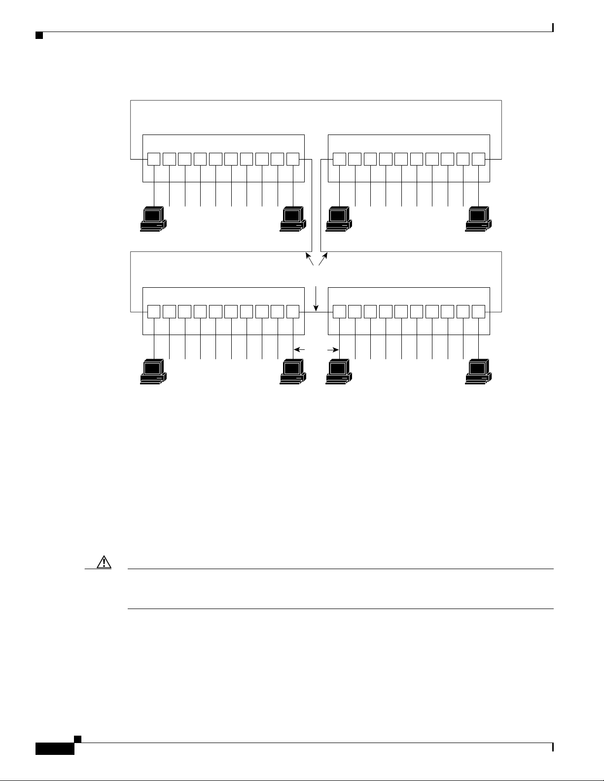
In the typical Token Ring network shown in Figure 1, lobe cables connect each Token Ring station (4R
port adapter interface) to the MSAU (or MAU), and patch cables connect adjacent MSAUs (or MAUs)
to form one large ring.
OL-3589-01
PA-4R Half-Duplex Token Ring Port Adapter Installation and Configuration
7
Page 8
Port Adapter Installation Prerequisites
Figure 1 Token Ring Network Physical Connections
MAU or MSAU
Ring
in12345678
Stations
MAU or MSAU
Ring
in12345678
Stations
Ring
out
Ring
out
Patch
cables
Lobe
cables
MAU or MSAU
Ring
in12345678
Stations
MAU or MSAU
Ring
in12345678
Stations
Ring
out
Ring
out
H2058
Token Ring Connection Equipment
You will need an 802.5 MAU or an MSAU to provide the interface between the 4R port adapter Token
Ring interfaces and the external ring, and a Token Ring lobe cable between each 4R port adapter
interface and the MAU or MSAU. Lobe cables connect each Token Ring station (4R port adapter
interface) to the MAU or MSAU, and patch cables can connect adjacent MSAUs to form one large ring.
4R port adapter interfaces operate at either 4 or 16 Mbps. The default speed for all 4R port adapter
interfaces is 4 Mbps, which you can change to 16 Mbps on any port using the ring-speed n configuration
command, where n is the speed (4 or 16) in Mbps. The speed of each Token Ring port must match the
speed of the ring to which it is connected. Before you enable the Token Ring interfaces, ensure that each
is set for the correct speed, or it can bring down the ring.
Caution Each 4R port adapter interface must be configured for the same ring speed as the ring to which it is
connected, either 4 or 16 Mbps. If the port is set for a different speed, it will cause the ring to beacon,
which effectively brings the ring down and makes it inoperable.
Token Ring Distance Limitations
The maximum transmission distance is not defined for IEEE 802.5 (Token Ring) networks. Shielded
twisted-pair (STP) cabling is most commonly used for rates of 4 and 16 Mbps. Twisted-pair cabling is
more susceptible to interference than other types of cabling; therefore, the network length and repeater
spacing should be planned accordingly.
PA-4R Half-Duplex Token Ring Port Adapter Installation and Configuration
8
OL-3589-01
Page 9
Token Ring Speed Considerations
Before you install the 4R port adapter, determine the ring speed (4 or 16 Mbps) of each ring to be
connected to the server. There is no factory default for the interface speed; you must set the speed of
each interface (within the setup command facility or with the ring-speed command) before you bring
the interface up and insert it into the ring with the no shutdown command.
Caution Each Token Ring port must be configured for the same ring speed as the ring to which it is connected;
either 4 or 16 Mbps. If the port is set for a different speed, it will cause the ring to beacon, which
effectively brings the ring down and makes it inoperable.
What Is the 4R Port Adapter?
The following sections provide additional information specific to the 4R port adapter:
• Port Adapter Locations on the VIP2 and the Cisco 7200 Series Router, page 9
• 4R Port Adapter LEDs, page 11
What Is the 4R Port Adapter?
• 4R Port Adapter Receptacles, Cables, and Pinouts, page 12
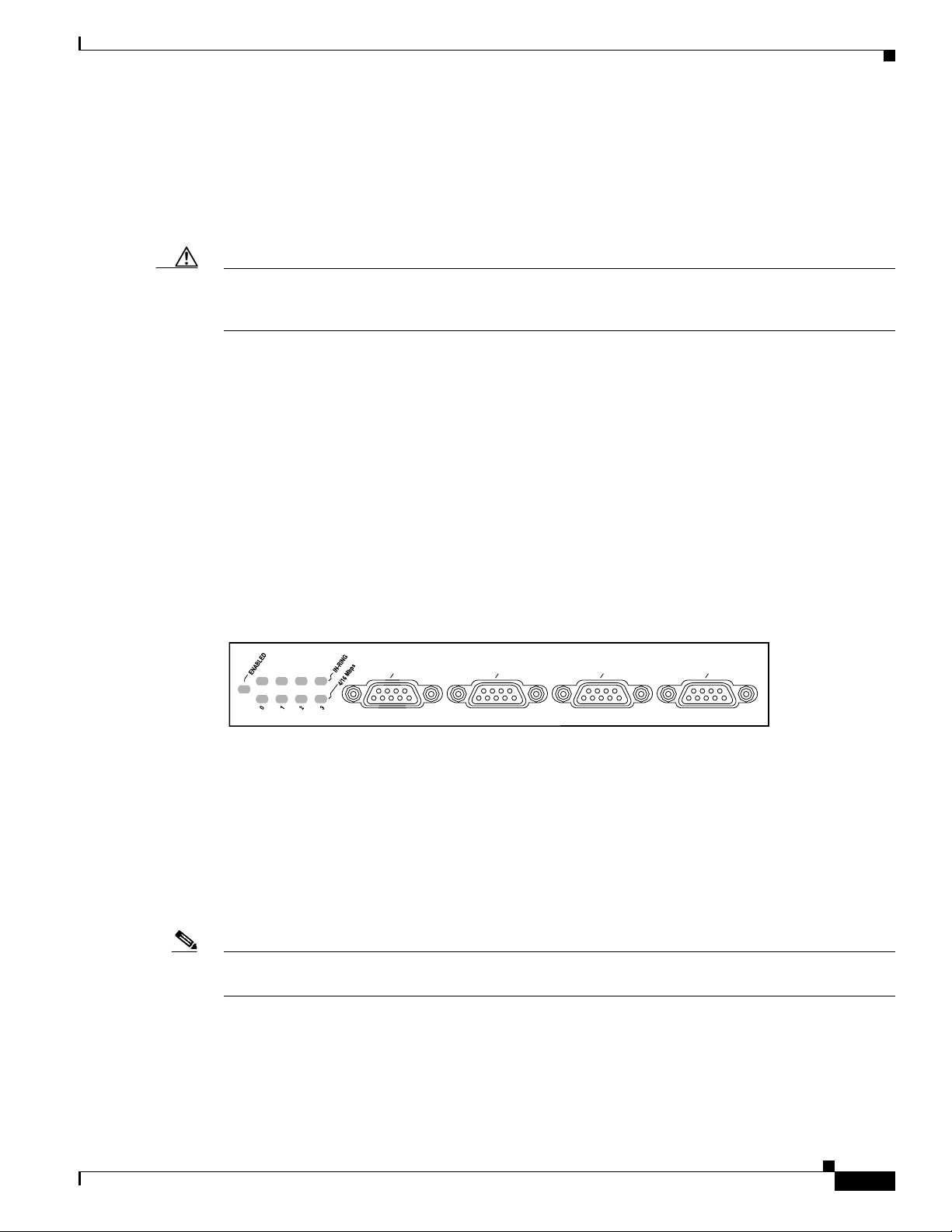
The 4R port adapter (see ) provides up to four IBM Token Ring or IEEE 802.5 Token Ring interfaces.
Each Token Ring interface can be set for 4 Mbps or 16 Mbps. All Token Ring ports on PA-4R are half
duplex (only) and run at wire speed.
Figure 2 4R Port Adapter (Faceplate View)
TOKEN RING
0
1
2
3
The 4R port adapter can be installed on the VIP2 in port adapter slot 0 and port adapter slot 1, or in the
Cisco 7200 series routers in any of the chassis’ port adapter slots: slot 1 and slot 2 of the Cisco 7202,
slots 1 through 4 of the Cisco 7204,and slots 1 through 6 of the Cisco 7206..
Port Adapter Locations on the VIP2 and the Cisco 7200 Series Router
This section provides information about where you can install the 4R port adapter on the VIP2 and in
the Cisco 7200 series routers.
H4493
OL-3589-01
Note Port adapters have handles that allow for easy installation and removal; however, they are occasionally
not shown in this publication to highlight port adapter faceplate detail.
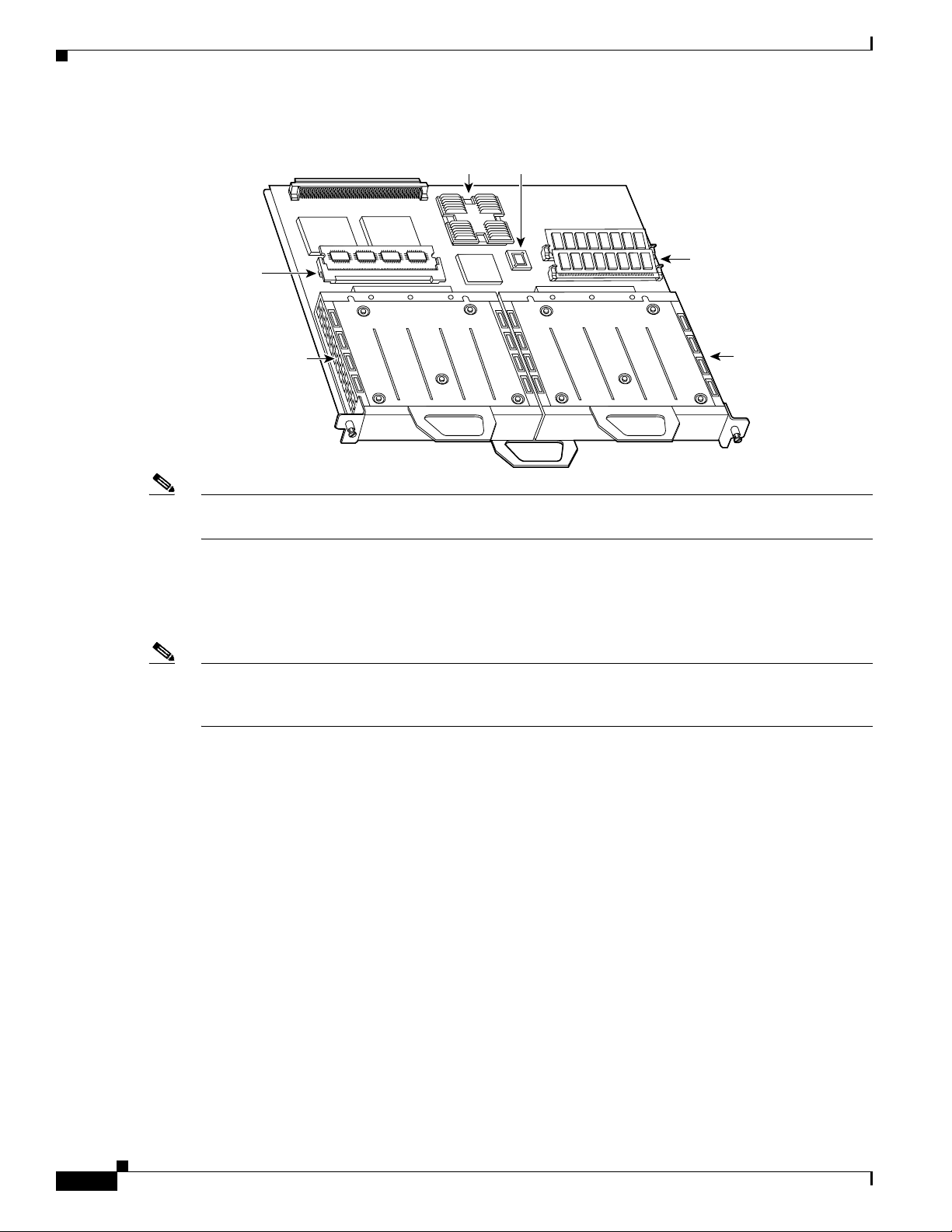
shows a VIP2-15 or VIP2-40 with two installed port adapters. With the VIP2 oriented as shown, the left
port adapter is in port adapter slot 0, and the right port adapter is in port adapter slot 1.
PA-4R Half-Duplex Token Ring Port Adapter Installation and Configuration
9
Page 10
What Is the 4R Port Adapter?
r
Figure 3 Two Port Adapters on the VIP2-15 or VIP2-40 (Horizontal Orientation Shown)
Boot ROM
U6
U2
U4
DRAM
SIMMs
Port adapte
in slot 1
H6448
SRAM
DIMM U5
Port adapter
in slot 0
Bus connector
CPU
Note In the Cisco 7000, Cisco 7507, and Cisco 7513 chassis, the VIP2 is installed vertically. In the Cisco 7010
and Cisco 7505 chassis, the VIP2 is installed horizontally.
In the Cisco 7200 series routers, port adapter slots are numbered from the lower left to the upper right,
beginning with port adapter slot 1 and continuing through port adapter slot 2 for the Cisco 7202, slot 4
for the Cisco 7204, and slot 6 for the Cisco 7206. Port adapter slot 0 is reserved for the optional Fast
Ethernet port on the I/O controller.
Note The I/O controller is available with or without a Fast Ethernet port. You can install both I/O controller
types in all Cisco 7200 series routers; however, when you install an I/O controller with a Fast Ethernet
port in a Cisco 7202, the system software automatically disables the port.
Figure 4 shows a Cisco 7206 with installed port adapters and an I/O controller with a Fast Ethernet port.
Not shown are the Cisco 7202, which has two port adapter slots, and the Cisco 7204, which has four port
adapter slots. The 4R-FDX port adapter can be installed in any available port adapter slot in the
Cisco 7200 series routers.
10
PA-4R Half-Duplex Token Ring Port Adapter Installation and Configuration
OL-3589-01
Page 11
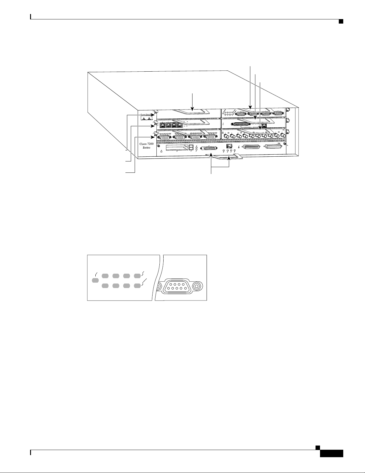
Figure 4 Port Adapters in the Cisco 7206
Blank port adapter
5
3
2
1
Port adapter slot 5
Port adapter slot 3
0
3
ENABLED
N
E
C
D
C
D
R
R
T
T
1
ENABLED
LINK
3
1
2
0
C
D
D
C
B
D
C
D
D
B
C
L
PCMCIA
T
T
C
L
R
R
T
T
EJECT
SLOT 0
What Is the 4R Port Adapter?
Port adapter slot 6
Port adapter slot 4
Port adapter slot 2
TOKEN RING
6
3
2
1
0
ETHERNET 10BT
ENABLED
FAST SERIAL
N
E
D
C
B
D
C
D
D
C
B
D
R
R
SLOT 1
C
L
R
R
T
T
C
L
FE MII
X
X
X
R
T
R
0
5
4
J
R
MII
RJ45
RJ45
EN
OK
EN
1O PWR
LINK
X
T
1
T
E
S
E
R
U
P
C
K
II
IN
L
M
0
X
X
T
R
2
FAST ETHERNET INPUT/OUTPUT CONTROLLER
FAST ETHERNET
5
4
J
R
X
X
T
R
3
ETHERNET-10BFL
X
R
4
X
T
2
4
0
H6422
Port adapter slot 1
4R Port Adapter LEDs
The 4R port adapter has several LEDs that indicate status of the port adapter and its interfaces. After
system initialization, the enabled LED goes on to indicate that the 4R port adapter has been enabled for
operation. (The LEDs are shown in .)
Figure 5 4R Port Adapter LEDs (Partial Faceplate View)
ENABLED
0
The following conditions must be met before the enabled LED goes on:
• The port adapter is enabled for operation and correctly connected
• The port adapter is receiving power
• The system contains a valid microcode version for the port adapter
If any of these conditions is not met, or if the initialization fails for other reasons, the port adapter’s
enabled LED does not go on.
Port adapter slot 0
TOKEN RING
IN-RING
4/16 Mbps
3
2
1
H4489
OL-3589-01
When a Token Ring interface is configured by using software commands, the In Ring and 4/16 Mbps
LEDs (shown in ) indicate the following for each port:
• In ring—Goes on when the interface is currently active and inserted into the ring; off when the
interface is not active and is not inserted into a ring.
• 4/16 Mbps—Goes on if the interface is operating at 16 Mbps; off when the interface is operation at
4 Mbps (default).
PA-4R Half-Duplex Token Ring Port Adapter Installation and Configuration
11
Page 12
What Is the 4R Port Adapter?
4R Port Adapter Receptacles, Cables, and Pinouts
A network interface cable provides the connection between the 9-pin Token Ring receptacles on the 4R
port adapter and a media access unit (MAU). The 9-pin connector at the 4R port adapter end and the
MAU connector at the network end are described in the section “Token Ring Connection Equipment” on
page 8.
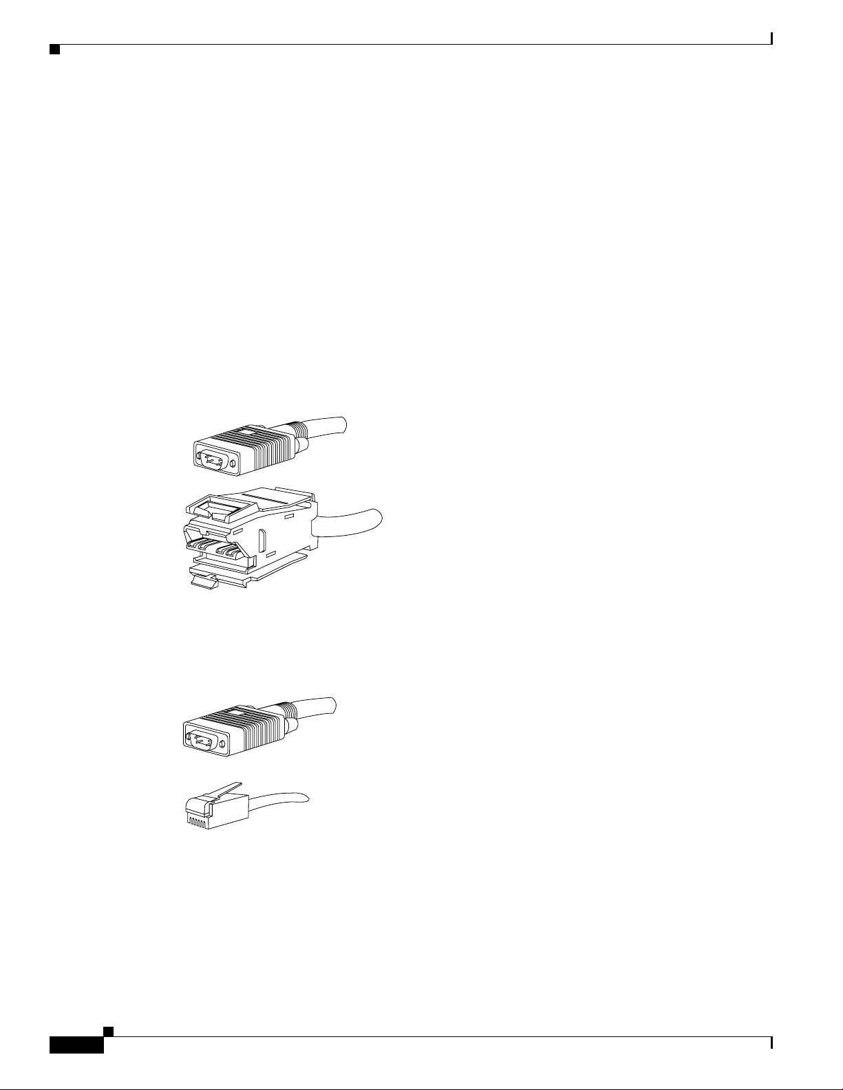
4R Port Adapter Cables
The Token Ring ports on the 4R port adapter are DB-9 (PC type) receptacles that require Type 1 or Type
3 lobe cables. Token Ring interface cables are not available from Cisco Systems, but are commercially
available through outside cable vendors.
Type 1 lobe cables use shielded twisted-pair (STP) cable and terminate at the network end with a large
MAU plug. (See Figure 6.) The 4R port adapter end of the cable is a DB-9 plug.
Figure 6 Token Ring Type 1 Lobe Cable Connectors (DB-9 and MAU Types)
4R port adapter end
MSAU or
MAU end
H5761
Type 3 lobe cables use either shielded or unshielded twisted-pair (UTP) cable and terminate at the
network end with an RJ-11 plug. (See .) The 4R port adapter end of the cable is a DB-9 plug.
Figure 7 Token Ring Type 3 Lobe Cable Connectors (DB-9 and RJ-11 Types)
4R port adapter end
MAU end
H5762
12
PA-4R Half-Duplex Token Ring Port Adapter Installation and Configuration
OL-3589-01
Page 13

4R Port Adapter Receptacle Pinout
Table 2 lists the pinout for the DB-9 receptacle used on the 4R port adapter.
Table 2 Token Ring Signals
Pin Signal
1 Ring-In B
5 Ring-Out A
6 Ring-In A
9 Ring-Out B
10 and 11 Ground
VIP2 and the 4R Port Adapter
VIP2 and the 4R Port Adapter
This section describes the 4R port adapter and its use with the VIP2 and provides the following
additional information specific to the 4R port adapter and its use on the VIP2 in Cisco 7000 series and
Cisco 7500 series routers:
• Installing or Replacing a Port Adapter on a VIP2, page 14
• Attaching 4R Port Adapter Interface Cables, page 18
• Configuring the 4R Interfaces, page 19
• Checking the Configuration, page 24
The 4R port adapter can be installed in either port adapter slot 0 or port adapter slot 1 on the VIP2. shows
a 4R port adapter installed in port adapter slot 0, on a VIP2-15 or VIP2-40.
OL-3589-01
PA-4R Half-Duplex Token Ring Port Adapter Installation and Configuration
13
Page 14

VIP2 and the 4R Port Adapter
Figure 8 VIP2-15 or VIP2-40 with a 4R Port Adapter in Port Adapter Slot 0
Bus connector
CPU
Boot ROM
U6
SRAM
U4
U2
DRAM
SIMMs
DIMM U5
4R in port
adapter
4T in port
adapter slot 1
slot 0
EN
TC
RD
TD
TD
RC
CD
LB
TD
RC
TC
RD
CD
LB
FAST SERIAL
TD
TC
RD
RC
TC
RD
CD
RC
LB
CD
LB
H6452
Port adapter
handles not shown
EN
TD
TC
RD
LB
RC
CD
Port adapters have a handle attached, but this handle is not shown to allow a full view of detail on each
port adapter’s faceplate.
Installing or Replacing a Port Adapter on a VIP2
Depending on the circumstances, you might need to install a new port adapter on a VIP2 motherboard
or replace a failed port adapter in the field. In either case, you need a number 1 Phillips screwdriver, an
antistatic mat onto which you can place the removed interface processor, and an antistatic container into
which you can place a failed port adapter for shipment back to the factory.
Caution To prevent system problems, do not remove port adapters from the VIP2 motherboard, or attempt to
install other port adapters on the VIP2 motherboard, while the system is operating. To install or replace
port adapters, first remove the VIP2 from its interface processor slot.
Note Each port adapter circuit board is mounted to a metal carrier and is sensitive to ESD damage. Each port
adapter has one Phillips-head screw that secures it to its port adapter slot. We strongly recommend that
the following procedures be performed by a Cisco-certified service provider; however, this is not a
requirement.
While the VIP2 supports online insertion and removal, individual port adapters do not. To replace port
adapters, you must first remove the VIP2 from the chassis, then install or replace port adapters as
required. If a blank port adapter is installed on the VIP2 in which you want to install a new port adapter,
you must first remove the VIP2 from the chassis, then remove the blank port adapter.
14
PA-4R Half-Duplex Token Ring Port Adapter Installation and Configuration
OL-3589-01
Page 15

VIP2 and the 4R Port Adapter
Caution To prevent interface reconfiguration requirements, you should replace a port adapter with the same type
of port adapter you removed, but this is not a requirement.
When only one port adapter is installed on a VIP2, a blank port adapter must fill the empty slot to allow
the VIP2 and router chassis to conform to electromagnetic interference (EMI) emissions requirements,
and so that air flows through the chassis properly. If you plan to install a new port adapter, you must first
remove the blank port adapter.
Use the following standard procedure to remove and replace any type of port adapter on a VIP2:
Step 1 Attach an ESD-preventive wrist strap between you and an unfinished chassis surface.
Note If you want to install a new port adapter on a VIP2 with a single port adapter, you must first
remove the blank port adapter from the port adapter slot in which you want to install the new
port adapter.
Step 2 For a new port adapter installation or a port adapter replacement, disconnect any interface cables from
the ports on the front of the port adapter, although, this is not required. You can remove VIP2s with
cables attached; however, we do not recommend it.
Step 3 Remove the VIP2 from the system. (Follow the steps in the section “Removing a VIP2” in the
configuration note Second-Generation Versatile Interface Processor (VIP2) Installation and
Configuration [Document Number 78-2658-xx], which shipped with your VIP2.) Place the removed
VIP2 on an antistatic mat.
Step 4 Locate the screw at the rear of the port adapter (or blank port adapter) to be replaced. (See .) This screw
secures the port adapter (or blank port adapter) to its slot.
Figure 9 Location of Port Adapter Screw (Partial Port Adapter View)
H3148
Screw
Step 5
Step 6 With the screw removed, grasp the handle on the front of the port adapter (or blank port adapter) and
Remove the screw that secures the port adapter (or blank port adapter).
carefully pull it out of its slot, away from the edge connector at the rear of the slot. (See .)
OL-3589-01
PA-4R Half-Duplex Token Ring Port Adapter Installation and Configuration
15
Page 16

VIP2 and the 4R Port Adapter
Figure 10 Pulling a Port Adapter Out of a Slot (Partial Port Adapter View)
H3149
Step 7
If you removed a port adapter, place it in an antistatic container for safe storage or shipment back to the
factory. If you removed a blank port adapter, no special handling is required; however, store the blank
port adapter for potential future use.
Step 8 Remove the new port adapter from its antistatic container and position it at the opening of the slot. (See
Figure 11.)
Step 9 Carefully align the port adapter carrier between the upper and lower edges of the port adapter slot, as
shown in Figure 11.
Figure 11 Aligning a Port Adapter in a Port Adapter Slot
H3150
16
Carrier
Upper edge
Lower edge
Caution To prevent jamming the carrier between the upper and lower edges of the port adapter slot and to ensure
that the edge connector at the rear of the port adapter seats in the connector at the rear of the port adapter
slot, make certain that the leading edges of the carrier are between the upper and lower slot edges, as
shown in the cutaway in Figure 11.
PA-4R Half-Duplex Token Ring Port Adapter Installation and Configuration
OL-3589-01
Page 17

Caution To ensure a positive ground attachment between the port adapter carrier and the VIP2 motherboard and
port adapter slot, and to ensure that the connectors at the rear of the port adapter and slot seat properly,
position the carrier between the upper and lower slot edges, as shown in Figure 12.
Step 10 Carefully slide the new port adapter into the port adapter slot (Figure 12) until the connector on the port
adapter is completely seated in the connector on the motherboard.
Figure 12 Port Adapter Installed in a Port Adapter Slot (Partial Port Adapter View)
VIP2 and the 4R Port Adapter
H3152
OL-3589-01
Step 11
Replace the screw in the rear of the port adapter slot. (See for its location.) Do not overtighten this
screw.
Step 12 Reinstall the VIP2 in the system. (Follow the steps in the section “Installing a VIP2” in the
configuration note Second-Generation Versatile Interface Processor (VIP2) Installation and
Configuration [Document Number 78-2658-xx], which shipped with your VIP2.)
Step 13 If disconnected, reconnect the interface cables to the port adapters.
This completes the procedure for installing a new port adapter or replacing a port adapter on a VIP2.
PA-4R Half-Duplex Token Ring Port Adapter Installation and Configuration
17
Page 18

VIP2 and the 4R Port Adapter
Attaching 4R Port Adapter Interface Cables
The Token Ring ports on the 4R port adapter run at either 4- or 16 Mbps. You need one Token Ring
interface cable for each 4R port adapter interface you want to use. Token Ring interface cables are not
available from Cisco Systems, but are commercially available through outside cable vendors. Port
adapters have a handle attached (see ), but this handle is not shown in to allow a full view of detail on
the 4R port adapter’s faceplate.
Use the following procedure to attach Token Ring cables to the 4R port adapter:
Step 1 Determine which 4R port adapter ports you want to use.
Note The IBM Token Ring specifies a star topology, with all end stations connected through a device called
an MSAU. IEEE 802.5 does not specify any topology, although most implementations are based on a star
configuration with end stations attached to a device called an MAU. Also, IBM Token Ring specifies
twisted-pair cabling, whereas IEEE 802.5 does not specify media type. Most Token Ring networks use
shielded twisted-pair (STP) cabling; however, some networks that operate at 4 Mbps use UTP cable.
Step 2 Attach the port adapter end of a Token Ring interface cable, or other connection equipment, to the
interface port. (See Figure 13).
Figure 13 Token Ring Interface Cable Connections
0
To MAU or MSAU
Caution Each 4R port adapter interface must be configured for the same ring speed as the ring to which it is
1
2
3
H6764
connected; either 4 or 16 Mbps. If the 4R port adapter interface is set for a different speed, it will cause
the ring to beacon, which effectively brings the ring down and makes it inoperable.
Step 3 Attach the network end of the Token Ring interface cable to the appropriate Token Ring equipment
atyour site: a MAU or MSAU.
18
This completes the procedure for attaching interface cables to the 4R port adapter.
PA-4R Half-Duplex Token Ring Port Adapter Installation and Configuration
OL-3589-01
Page 19

Configuring the 4R Interfaces
The following procedures describe basic configuration information for the 4R port adapter. If you
installed a new 4R port adapter or if you want to change the configuration of an existing interface, you
must enter configuration mode using the configure command. If you replaced a 4R port adapter that was
previously configured, the system will recognize the new 4R interfaces and bring them up in their
existing configuration.
After you verify that the new 4R port adapter is installed correctly (the enabled LED goes on), use the
privileged-level configure command to configure the new interfaces. Be prepared with the information
you will need, such as the following:
• Protocols you plan to route on each new interface
• Internet protocol (IP) addresses if you plan to configure the interfaces for IP routing
• Whether the new interfaces will use bridging
Note The 4R interfaces on a VIP2 can be configured for 16-Mbps operation and are configured for 4-Mbps
operation as a default.
For a summary of the configuration options available and instructions for configuring the 4R interfaces
on the VIP2, refer to the appropriate configuration publications listed in the section “If You Need More
Information” on page 2.
VIP2 and the 4R Port Adapter
Determining Chassis Slot, Port Adapter, and Token Ring Interface Port Numbers
The following section describes how to identify chassis slot, port adapter, and Token Ring interface port
numbers.
Note Although the processor slots in the seven-slot Cisco 7507 and 13-slot Cisco 7513 are vertically oriented
and those in the five-slot Cisco 7505 are horizontally oriented, all models use the same method for slot
and port numbering.
In the router, physical port addresses specify the actual physical location of each interface port on the
router interface processor end. (See .) This address is composed of a three-part number in the format
chassis slot number/port adapter number/interface port number, as follows:
• The first number identifies the chassis slot in which the VIP2 is installed (as shown in the example
system in ).
• The second number identifies the physical port adapter number on the VIP2, and is either 0 or 1.
• The third number identifies interface ports on each 4R port adapter and are always numbered in
sequence as interface 0 through 3.
Interface ports on the 4R port adapter maintain the same address regardless of whether other interface
processors are installed or removed. However, when you move a VIP2 to a different slot, the first number
in the address changes to reflect the new slot number.
shows some of the slot port adapter and interface ports of a sample Cisco 7505 system. The first port
adapter slot number is always 0. The second port adapter slot number is always 1. The individual
interface port numbers always begin with 0. The number of additional ports depends on the number of
ports on a port adapter.
OL-3589-01
PA-4R Half-Duplex Token Ring Port Adapter Installation and Configuration
19
Page 20

VIP2 and the 4R Port Adapter
For example, the addresses for the 4R interface ports on the first port adapter on a VIP2 (see ) are 3/0/0
through 3/0/3 (chassis slot 3, port adapter slot 0, and interface ports 0 through 3). If the 4R port adapter
were installed in port adapter slot 1, the interface addresses would be 3/1/0 through 3/1/3.
Note If you remove the 4R-equipped VIP2 (shown in ) from chassis slot 3 and install it in slot 2, the addresses
of those same ports become 2/0/0 through 2/0/3.
Figure 14 4R Token Ring Interface Port Number Example (Cisco 7505 Shown)
4R port adapter
(port numbers 3/0/0, 3/0/1,
3/0/2, 3/0/3, from left to right)
T
C
T 1
JE
L
A
M
R
O
N
IN USE
4/16 MB
ENAB
2
2
E
LO
S
T 0
LO
S
2
1
0
P
C
D
T
3
OCESSOR
ITCH PR
E SW
LT
A
T
H
SE
U
E
R
C
D
D
C
B
D
C
D
T
T
L
C
R
R
T
T
ROUT
LE
O
S
N
O
C
IAL
FAST SER
D
C
B
D
C
D
D
C
B
D
L
C
D
D
C
B
D
T
T
L
C
R
R
C
R
R
T
T
L
C
R
R
Slot 3
Slot 2
Slot 1
Interface
processor
slots
Slot 0
You can identify interface ports by physically checking the slot/port adapter/interface port location on
the back of the router or by using software commands to display information about a specific interface
or all interfaces in the router.
Using the EXEC Command Interpreter
You can modify the startup configuration for Cisco 7500 series routers through the software command
interpreter called EXEC. To configure the interfaces for interface processors, you can use either one of
the setup or configure EXEC commands.
The setup command facility can be used after first time startup to make basic changes at any time. The
changes you make will affect only the changed elements’ current memory values that are stored in
nonvolatile memory.
The configure privileged EXEC command enables you to perform advanced configurations such as
specifying interfaces. The EXEC interprets the commands you enter and carries out the corresponding
operations. You can list available EXEC commands by entering a question mark (?). You also can enter
a question mark to obtain more information about commands. For example, enter terminal ? to obtain
a list of terminal commands or show ? to obtain a list of show commands.
Before you use the setup or the configure command, you must have privileged access to the EXEC
command interpreter. The system prompt for the privileged level ends with a pound sign (#) instead of
an angle bracket (>). The EXEC enable command allows access to the privileged level, prompting for a
password if one has been set with the enable-password configuration command.
H5987
20
Follow these steps to enter the privileged level of the EXEC.
Step 1 At the EXEC prompt for a router, enter the enable command:
PA-4R Half-Duplex Token Ring Port Adapter Installation and Configuration
OL-3589-01
Page 21

Router> enable
The EXEC prompts you for a privileged level password:
Password:
Step 2 Enter the password.
For security purposes, the password is not displayed. (Also note that the password is case sensitive).
When you enter the correct password, the system displays the privileged mode system prompt:
Router#
To configure Token Ring interfaces using the setup EXEC command facility, follow the instructions in
the section “Using the Setup Command Facility.” To configure the Token Ring interfaces by using the
configure EXEC command, follow the instructions in the section “Determining Chassis Slot, Port
Adapter, and Token Ring Interface Port Numbers” on page 19.
Using the Setup Command Facility
The setup command facility identifies all interfaces (including the Token Ring interfaces for the ports
on the 4R port adapter) that are installed and prompts you for configuration information for each
installed interface. When you finish configuring one interface, the setup command facility prompts you
for the next, continuing until each interface has been configured.
VIP2 and the 4R Port Adapter
When you enter the setup command facility after first time startup, you must run through the entire
dialog until you come to the interface you want to change. Note that when you use the setup command
after first time startup, the default values indicated within the brackets in the System Configuration
Dialog are the values last set using the setup command facility or left as defaults.
After you choose to continue with the setup command (by answering yes to the system configuration
dialog prompt), the remainder of the script is the actual configuration process. The dialog prompts you
first for global system parameters, then for configuration information for each interface. The existing
configuration is displayed as the default, in brackets ([ ]), at the end of each prompt. Press Return to
accept the default settings.
Note After you start the setup command facility, the system runs through the entire configuration process; you
cannot quit out of it. To make a change or correct a mistake, press the Return key at each prompt, answer
no when asked if you want to save the configuration, and restart the setup facility.
Use the setup command facility to configure the 4R Token Ring interfaces, as follows:
Step 1 After you access the privileged level of the EXEC, as described in the section “Using the EXEC
Command Interpreter” on page 20, enter the setup command to begin the setup facility:
Router# setup
Step 2 The following script is displayed on the screen, with the name of your router as the default in the
brackets.
-System Configuration DialogAt any point you may enter a question mark ‘?’ for help.
Refer to the ‘Getting Started’ Guide for additional help.
Default settings are in square brackets ‘[]’.
Continue with configuration dialog? [yes]:
OL-3589-01
PA-4R Half-Duplex Token Ring Port Adapter Installation and Configuration
21
Page 22

VIP2 and the 4R Port Adapter
(Use Ctrl-c to abort configuration at any prompt)
Configuring global parameters:
Enter host name [Router]: sandbox
Step 3 To accept the default and keep the router name, press Return. (If you do want to change the name of
the router, enter the new name before pressing Return.)
Step 4 Proceed through the remainder of the global parameter prompts, using the Return key to accept the
defaults.
After the global parameters are configured, the system prompts you for interface configuration
information, one interface at a time. Following is a partial display of the script for a previously
configured interface:
Configuring interface parameters:
Configuring interface Token Ring0:
Is this interface in use [yes]:
Tokenring ring speed (4 or 16) [16]
Configure IP on this interface? [yes]:
IP address for this interface: 1.1.1.30
(remainder of display text omitted)
Caution Each 4R port adapter interface must be configured for the same ring speed as the ring to which
it is connected; either 4 or 16 Mbps. If the 4R port adapter interface is set for a different speed,
it will cause the ring to beacon, which effectively brings the ring down and makes it
inoperable.
Step 5 To accept the default at each prompt and retain the existing configuration information, press the Return
key. When you reach the scripts for configuring new interfaces, enter the new configuration information
at each prompt.
When all interfaces are configured, the system displays the entire configuration script followed by a
prompt for which there is no default (you must enter yes or no):
Use this configuration [yes/no]:
Step 6 To use the configuration you created, enter yes. To discard the configuration file and begin the
configuration process again, enter no.
If you entered yes at the prompt, the following message is displayed:
Press RETURN to get started!
The configuration process is complete. Proceed to the section “Checking the Configuration” on page 24.
It provides show commands you can use to display and verify the configuration information.
Configuring Interfaces Using the configure Command
22
Following are instructions for a basic configuration using the configure command: enabling an interface,
setting interface ring speed, and specifying IP routing. You might also need to enter other configuration
subcommands depending upon the requirements for your system configuration. Press the Return key
after each step unless otherwise noted. At any time you can exit the privileged level and return to the
user level by entering disable at the prompt as follows:
Router# disable
PA-4R Half-Duplex Token Ring Port Adapter Installation and Configuration
OL-3589-01
Page 23

VIP2 and the 4R Port Adapter
Router>
Use the following procedure to perform a basic configuration:
Step 1 After you access the privileged level of the EXEC as described in the section “Using the EXEC
Command Interpreter” on page 20, enter the configure command:
Router# configure terminal
Enter configuration commands, one per line. End with CNTL/Z.
Step 2 Specify the first Token Ring interface to configure by entering the subcommand interface type slot/port
adapter/interface. For example, if you are configuring Token Ring interface 0 for a 4R port adapter
installed in port adapter slot 0, on a VIP2 installed in chassis slot 3, enter the following command:
Router(config)# interface tokenring 3/0/0
Step 3 If IP routing is enabled on the system, you can assign an IP address and subnet mask to the interface
with the ip address configuration subcommand as follows:
Router(config-if)# ip address ip address subnet mask
Caution Each Token Ring port must be configured for the same ring speed as the ring to which it is
connected; either 4 or 16 Mbps. If the port is set for a different speed, it will cause the ring to
beacon, which effectively brings the ring down and makes it inoperable.
Note Token Ring ports operate at either 4 or 16 Mbps. The default speed for the 4R port adapter’s
Token Ring ports is 4 Mbps, which you can change to 16 Mbps on any port using the
configuration ring-speed n command, where n is the speed (4 or 16) in Mbps. Before you enable
the Token Ring interfaces, ensure that each is set for the correct speed, or it can bring down the
ring.
Step 4 Change the default shutdown state and enable the interface:
Router(config-if)# no shutdown
When you enable the interface by using the no shutdown command, the LED for 4 Mbps or 16 Mbps is
turned on after about 5 seconds. The In Ring LED for that interface is turned on about 5 to 18 seconds
later, when the port is initialized and connected to the ring.
Step 5 Either accept the default ring speed of 4 Mbps, or enable the Token Ring interface speed for 16-Mbps
operations as follows:
Router(config-if)# ring-speed 16
Step 6 Enter any additional configuration subcommands required.
Step 7 Repeat Steps 2 through 6 for each new interface.
Step 8 When all new interfaces are configured, press Ctrl-Z (hold the Control key down and press the Z key).
Step 9 Write the new configuration to nonvolatile memory by entering the following:
Router# copy running-config startup-config
[OK]
Router#
OL-3589-01
Step 10 Enter quit to exit configuration mode:
Router# quit
PA-4R Half-Duplex Token Ring Port Adapter Installation and Configuration
23
Page 24

VIP2 and the 4R Port Adapter
You have now completed configuring the Token Ring interfaces. Check the configuration as described
in the section “Checking the Configuration.”
Checking the Configuration
After configuring the new interface, use the show commands to display the status of the new interface
or all interfaces and the ping command to check connectivity. Refer to the publications listed in the
section “If You Need More Information” on page 2, for detailed command descriptions and examples.
Using show Commands to Verify the VIP2 Status
After configuring the new interface(s) using either the setup command or the configure command, use
the EXEC show commands to display status information.
Step 1 Display the system software and hardware configuration with the show version command. Ensure that
the list includes the new interfaces and that your system is running the appropriate Cisco IOS software
for your configuration.
Step 2 Enter the show configuration command to display the current system configuration file:
Router# show configuration
The configuration file for the router is displayed. Check the Token Ring configuration information in the
display.
Step 3 Enter the show interfaces command to display and check all interfaces:
Router# show interfaces
Each interface is listed along with its assigned IP address. Verify that each new Token Ring interface
appears.
Step 4 Enter the show interface tokenring slot/port adapter/port command to obtain detailed status
information about a specific Token Ring interface:
Router# show interface tokenring slot/port adapter/port
Detailed information about the interface is displayed. The first line of display specifies the interface
along with its slot and port number. It indicates whether the hardware is functional and if the line
protocol is up or down. If the line protocol is down (and you did not administratively shut it down), or
if the hardware is not functioning properly, ensure that the network interface is properly connected and
terminated. (For explanations of the displayed information, refer to publications listed in the section “If
You Need More Information,” on page 2, which are available on the Documentation CD-ROM.)
Step 5 Enter the show controller command to display the current status of VIP2s with 4R port adapters
installed:
Router# show controllers token
24
The display lists the Token Ring interfaces connected to each VIP2 and indicates whether the system has
identified your new interface. It does not indicate the state of the line or the protocol.
To display information about a specific interface, use the show interfaces command with the interface
type and port address in the format show interfaces [type slot/port adapter/port].
PA-4R Half-Duplex Token Ring Port Adapter Installation and Configuration
OL-3589-01
Page 25

VIP2 and the 4R Port Adapter
Following is an example of how the show interfaces [type slot/port adapter/port] command displays
status information (including the physical slot and port address) for the interfaces you specify. In these
examples, most of the status information for each interface is omitted, and the four Token Ring interfaces
(0–3) are in chassis slot 3, in port adapter slot 0. (Interfaces are administratively shut down until you
enable them.)
Router# sh int tokenring 3/0/0
TokenRing3/0/0 is administratively down, line protocol is down
Hardware is cyBus TokenRing, address is 0000.0ca5.2300 (bia 0000.0ca5.2389)
MTU 1500 bytes, BW 10000 Kbit, DLY 1000 usec, rely 255/255, load 1/255
Encapsulation ARPA, loopback not set, keepalive set (10 sec)
Router# sh int tokenring 3/0/1
TokenRing3/0/1 is administratively down, line protocol is down
Hardware is cyBus TokenRing, address is 0000.0ca5.2300 (bia 0000.0ca5.238a)
MTU 1500 bytes, BW 10000 Kbit, DLY 1000 usec, rely 255/255, load 1/255
Encapsulation ARPA, loopback not set, keepalive set (10 sec)
Router# sh int tokenring 3/0/2
TokenRing3/0/2 is administratively down, line protocol is down
Hardware is cyBus TokenRing, address is 0000.0ca5.2300 (bia 0000.0ca5.238b)
MTU 1500 bytes, BW 10000 Kbit, DLY 1000 usec, rely 255/255, load 1/255
Encapsulation ARPA, loopback not set, keepalive set (10 sec)
Router# sh int tokenring 3/0/3
TokenRing3/0/3 is administratively down, line protocol is down
Hardware is cyBus TokenRing, address is 0000.0ca5.2300 (bia 0000.0ca5.238b)
MTU 1500 bytes, BW 10000 Kbit, DLY 1000 usec, rely 255/255, load 1/255
Encapsulation ARPA, loopback not set, keepalive set (10 sec)
With the show interfaces type slot/port adapter/port command, use arguments such as the interface type
(Token Ring, and so forth) and the slot, port adapter, and port numbers (slot/port adapter/port) to display
information about a specific serial interface only.
The following example of the show interfaces tokenring slot/port adapter/port command shows all of
the information specific to the first 4R interface port (interface port 0) in chassis slot 3, port adapter
slot 0:
Router# sh int tokenring 3/0/0
TokenRing3/0/0 is administratively down, line protocol is down
Hardware is cyBus TokenRing, address is 0000.0ca5.2300 (bia 0000.0ca5.2388)
MTU 1500 bytes, BW 10000 Kbit, DLY 1000 usec, rely 255/255, load 1/255
Encapsulation ARPA, loopback not set, keepalive set (10 sec)
ARP type: ARPA, ARP Timeout 4:00:00
Last input never, output never, output hang never
Last clearing of “show interface” counters 2:56:26
Output queue 0/40, 0 drops; input queue 0/75, 0 drops
5 minute input rate 0 bits/sec, 0 packets/sec
5 minute output rate 0 bits/sec, 0 packets/sec
0 packets input, 0 bytes, 0 no buffer
Received 0 broadcasts, 0 runts, 0 giants
0 input errors, 0 CRC, 0 frame, 0 overrun, 0 ignored, 0 abort
0 input packets with dribble condition detected
0 packets output, 0 bytes, 0 underruns
0 output errors, 0 collisions, 0 interface resets, 0 restarts
0 output buffer failures, 0 output buffers swapped out
OL-3589-01
To determine which type of port adapter is installed on a VIP2 in your system, use the show diag slot
command. Specific port adapter information is displayed, as shown in the following example of two 4R
port adapters in chassis slot 8:
Router# show diag 8
Slot 8:
PA-4R Half-Duplex Token Ring Port Adapter Installation and Configuration
25
Page 26

VIP2 and the 4R Port Adapter
Physical slot 8, ~physical slot 0x7, logical slot 8, CBus 0
Microcode Status 0x4
Master Enable, LED, WCS Loaded
Board is analyzed
Pending I/O Status: None
EEPROM format version 1
VIP2 controller, HW rev 2.2, board revision UNKNOWN
Serial number: 03341418 Part number: 73-1684-02
Test history: 0x00 RMA number: 00-00-00
Flags: cisco 7000 board; 7500 compatible
EEPROM contents (hex):
0x20: 01 15 02 02 00 32 FC 6A 49 06 94 02 00 00 00 00
0x30: 07 2B 00 2A 1A 00 00 00 00 00 00 00 00 00 00 00
Slot database information:
Flags: 0x4 Insertion time: 0x3188 (01:20:53 ago)
Controller Memory Size: 8 MBytes
PA Bay 0 Information:
Token Ring PA, 4 ports
EEPROM format version 1
HW rev 1.1, Board revision 0
Serial number: 02827613 Part number: 73-1390-04
PA Bay 1 Information:
Token Ring PA, 4 ports
EEPROM format version 1
HW rev 1.1, Board revision 88
Serial number: 02023786 Part number: 73-1390-04
Using the ping Command
The ping command allows you to verify that an interface port is functioning properly and to check the
path between a specific port and connected devices at various locations on the network. This section
provides brief descriptions of the ping command. After you verify that the system and VIP2 have booted
successfully and are operational, you can use this command to verify the status of interface ports.
The ping command sends an echo request out to a remote device at an IP address that you specify. After
sending a series of signals, the command waits a specified time for the remote device to echo the signals.
Each returned signal is displayed as an exclamation point (!) on the console terminal; each signal that is
not returned before the specified time-out is displayed as a period (.). A series of exclamation points
(!!!!!) indicates a good connection; a series of periods (.....) or the messages [timed out] or [failed]
indicate that the connection failed.
Following is an example of a successful ping command to a remote server with the address 1.1.1.10:
Router# ping 1.1.1.10 <Return>
Type escape sequence to abort.
Sending 5, 100-byte ICMP Echoes to 1.1.1.10, timeout is 2 seconds:
!!!!!
Success rate is 100 percent (5/5), round-trip min/avg/max = 1/15/64 ms
Router#
If the connection fails, verify that you have the correct IP address for the server and
that the server is active (powered on), and repeat the ping command.
For complete descriptions of interface subcommands and the configuration options available for
VIP2-related interfaces, and which support VIP2 functionality, refer to the publications listed in the
section “If You Need More Information” on page 2.
26
PA-4R Half-Duplex Token Ring Port Adapter Installation and Configuration
OL-3589-01
Page 27

Cisco 7200 Series and the 4R Port Adapter
The 4R port adapter can be installed in any of the available port adapter slots in Cisco 7200 series routers
(which consists of the 2-slot Cisco 7202, 4-slot Cisco 7204, and the 6-slot Cisco 7206). shows a Cisco
7206 with a 4R port adapter installed in port adapter slot 6.
Figure 15 Cisco 7206 with a 4R Port Adapter in Port Adapter Slot 6
5
D
ETHERNET 10BT
E
T
C
FE MII
FAST SERIAL
D
R
L
B
A
N
E
N
E
D
C
B
C
L
R
X
X
T
R
0
MII
RJ-45
RJ-45
EN
EN
1O PWR
LINK
K
D
E
L
B
A
N
E
3
N
E
D
T
T
1
ENABLED
3
2
1
0
C
D
C
R
R
IN
L
3
1
2
0
D
C
B
D
C
D
D
B
C
L
R
R
T
T
C
L
PCMCIA
D
D
C
B
D
C
D
T
C
L
R
R
T
T
SLOT 1
EJECT
SLOT 0
Cisco 7200 Series and the 4R Port Adapter
4R port adapter
1
0
K
J45
II
R
LIN
M
0
X
X
X
X
R
RJ-45
OK
T
1
T
R
2
FAST ETHERNET INPUT/OUTPUT CONTROLLER
TOKEN RING
6
3
2
FAST ETHERNET
4
L
ET-10BF
ERN
ETH
X
X
X
X
R
T
R
T
3
2
4
0
H6762
The following sections include information specific to the 4R port adapter and its use in the Cisco 7200
series routers:
• Installing or Replacing a Port Adapter in Cisco 7200 Series Routers, page 27
• Attaching 4R Port Adapter Interface Cables, page 30
• Configuring the 4R Interfaces, page 31
Installing or Replacing a Port Adapter in Cisco 7200 Series Routers
This section provides the standard procedures for installing or replacing port adapters in a Cisco 7200
series router.
Depending on your circumstances, you might need to install a new port adapter in a Cisco 7200 series
router or replace a failed port adapter in the field. In either case no tools are necessary; all port adapters
available for the Cisco 7200 series connect directly to the router midplane and are locked into position
by a port adapter lever. When removing and replacing a port adapter, you will need an antistatic mat onto
which you can place a removed port adapter and an antistatic container into which you can place a failed
port adapter for shipment back to the factory.
Note The Cisco 7200 series routers support OIR; therefore, you do not have to power down the Cisco 7200
series routers when removing and replacing a port adapter.
When a port adapter slot is not in use, a blank port adapter must fill the empty slot to allow the router to
conform to EMI emissions requirements and to allow proper air flow across the port adapters. If you plan
to install a new port adapter in a slot that is not in use, you must first remove a blank port adapter.
OL-3589-01
PA-4R Half-Duplex Token Ring Port Adapter Installation and Configuration
27
Page 28

Cisco 7200 Series and the 4R Port Adapter
Removing a Port Adapter
Use the following standard procedure to remove a port adapter from a Cisco 7200 series router:
Step 1 Attach an ESD-preventive wrist strap between you and an unfinished chassis surface.
Step 2 Place the port adapter lever for the desired port adapter slot in the unlocked position. The port adapter
lever remains in the unlocked position. (Refer to Figure 16.)
Figure 16 Placing the Port Adapter Lever in the Unlocked Position (Cisco 7206 Shown)
TOKEN RING
6
3
2
1
ENABLED
0
FAST ETHERNET
5
K
4
J
II
IN
R
L
M
0
T
E
S
FAST ETHERNET INPUT/OUTPUT CONTROLLER
E
R
U
5
4
P
-
C
J
R
RJ45
RJ45
OK
EN
1O PWR
LINK
4
2
0
H6596
5
3
2
1
0
ENABLED
3
EN
RC
RD
TC
TD
1
ENABLED
LINK
3
1
2
0
TD
CD
LB
RC
RD
TC
TD
CD
LB
EJECT
PCMCIA
ETHERNET 10BT
FAST SERIAL
CD
LB
RC
RD
TC
TD
CD
LB
RC
RD
TC
FE MII
SLOT 1
MII
SLOT 0
EN
Port adapter
handle
Port adapter
Note: This adapter removal
applies to any port or service
lever (unlocked
position)
adapter.
Step 3
Grasp the handle on the port adapter and pull the port adapter from the midplane, about halfway out of
its slot. If you are removing a blank port adapter, pull the blank port adapter from the port adapter slot.
Note As you disengage the port adapter from the router midplane, OIR administratively shuts down
all active interfaces on the port adapter.
Step 4 With the port adapter halfway out of the slot, disconnect all cables from the port adapter.
Step 5 After disconnecting the cables, pull the port adapter from its port adapter slot.
Caution Always handle the port adapter by the carrier edges and handle; never touch the port adapter’s
components or connector pins. (Refer to Figure 17.)
28
PA-4R Half-Duplex Token Ring Port Adapter Installation and Configuration
OL-3589-01
Page 29

Figure 17 Handling a Port Adapter
Step 6
Place the port adapter on an antistatic surface with its components facing upward, or in a static
shielding bag. If the port adapter will be returned to the factory, immediately place it in a static
shielding bag.
This completes the procedure for removing a port adapter from a Cisco 7200 series router.
Replacing a Port Adapter
Cisco 7200 Series and the 4R Port Adapter
Metal carrier
Printed circuit board
H6420
Use the following standard procedure to install a new port adapter in a Cisco 7200 series router:
Step 1 Attach an ESD-preventive wrist strap between you and an unfinished chassis surface.
Step 2 Use both hands to grasp the port adapter by its metal carrier edges and position the port adapter so that
its components are downward. (Refer to ).
Step 3 Align the left and right edge of the port adapter metal carrier between the guides in the port adapter
slot. (Refer to Figure 18.)
Figure 18 Aligning the Port Adapter Metal Carrier Between the Slot Guides
(Cisco 7206 Shown)
TOKEN RING
6
3
2
1
Slot
guide
5
K
D
LE
B
A
3
N
E
1
ENABLED
3
2
1
0
IN
L
3
1
2
0
EJECT
PCMCIA
ETHERNET 10BT
FE MII
SLOT 1
MII
SLOT 0
EN
0
LED
AB
EN
5
4
J
R
RJ45
RJ45
OK
EN
1O PWR
LINK
T
E
S
E
R
U
P
C
K
II
LIN
M
0
FAST ETHERNET INPUT/OUTPUT CONTROLLER
FAST ETHERNET
J45
R
H6597
4
2
OL-3589-01
Note: This adapter alignment
applies to any port or service
adapter.
Step 4 With the metal carrier aligned in the slot guides, gently slide the port adapter halfway into the slot.
PA-4R Half-Duplex Token Ring Port Adapter Installation and Configuration
29
Page 30
Cisco 7200 Series and the 4R Port Adapter
Caution Do not slide the port adapter all the way into the slot until you have connected all required
cables. Trying to do so will disrupt normal operation of the router.
Step 5 With the port adapter halfway in the slot, connect all required cables to the port adapter.
Step 6 After connecting all required port adapter cables, carefully slide the port adapter all the way into the
slot until you feel the port adapter’s connectors seat in the midplane.
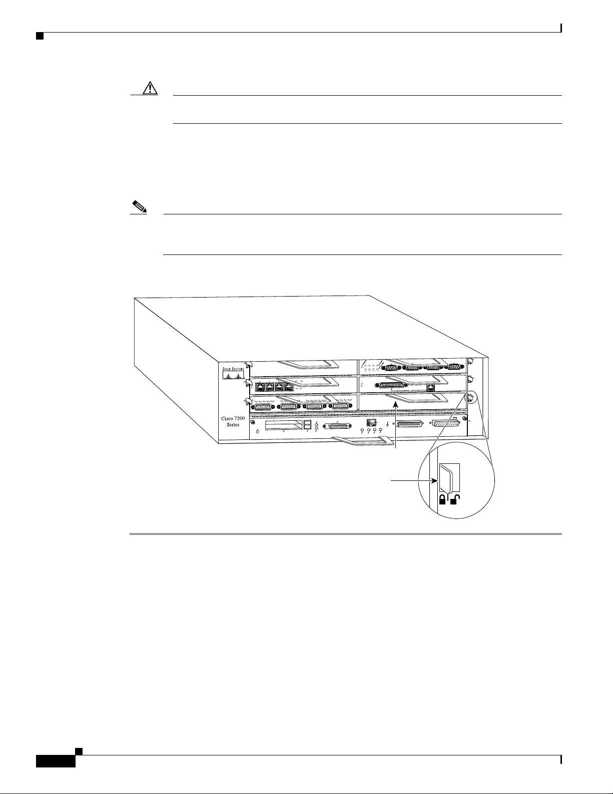
Step 7 Move the port adapter lever to the locked position. shows the port adapter lever in the locked position.
Note If the port adapter lever does not move to the locked position, the port adapter is not completely
seated in the midplane. Carefully pull the port adapter halfway out of the slot, reinsert it, and
move the port adapter lever to the locked position.
Figure 19 Placing the Port Adapter Lever in the Locked Position (Cisco 7206 Shown)
5
3
2
1
0
ENABLED
3
EN
RC
RD
TC
TD
1
ENABLED
LINK
3
1
2
0
RD
TC
TD
CD
LB
RC
RD
TC
TD
CD
LB
EJECT
PCMCIA
SLOT 0
Note: This adapter installation
applies to any port or service
adapter.
This completes the procedure for installing a new port adapter in a Cisco 7200 series router.
Attaching 4R Port Adapter Interface Cables
The Token Ring ports on the 4R port adapter run at either 4 or 16 Mbps. You need one Token Ring
interface cable for each 4R port adapter interface you want to use. Token Ring interface cables are not
available from Cisco Systems, but are commercially available through outside cable vendors. Port
adapters have a handle but this handle is not shown in to allow a full view of detail on the 4R port
adapter’s faceplate.
CD
LB
RC
SLOT 1
ETHERNET 10BT
FAST SERIAL
CD
LB
RC
RD
TC
TD
FE MII
Port adapter
lever (locked
position)
ENABLED
5
4
J
R
MII
RJ45
RJ45
EN
OK
EN
1O PWR
LINK
Port adapter
0
T
E
S
E
R
U
P
C
handle
2
1
5
K
4
J
II
IN
R
L
M
0
FAST ETHERNET INPUT/OUTPUT CONTROLLER
TOKEN RING
3
FAST ETHERNET
6
4
2
0
H6747
30
Use the following procedure to attach Token Ring cables to the 4R port adapter:
PA-4R Half-Duplex Token Ring Port Adapter Installation and Configuration
OL-3589-01
Page 31

Cisco 7200 Series and the 4R Port Adapter
Step 1 Determine which 4R port adapter ports you want to use.
Note The IBM Token Ring specifies a star topology, with all end stations connected through a device
called an MSAU. IEEE 802.5 does not specify any topology, although most implementations are
based on a star configuration with end stations attached to a device called an MAU. Also, IBM
Token Ring specifies twisted-pair cabling, whereas IEEE 802.5 does not specify media type.
Most Token Ring networks use shielded twisted-pair (STP) cabling; however, some networks
that operate at 4 Mbps use UTP cable.
Step 2 Attach the port adapter end of a Token Ring interface cable, or other connection equipment, to the
interface port. (See Figure 20).
Figure 20 Token Ring Interface Cable Connections
0
To MAU or MSAU
Caution Each 4R port adapter interface must be configured for the same ring speed as the ring to which
1
2
3
H6764
it is connected; either 4 or 16 Mbps. If the 4R port adapter interface is set for a different speed,
it will cause the ring to beacon, which effectively brings the ring down and makes it
inoperable.
Step 3 Attach the network end of the Token Ring interface cable to the appropriate Token Ring equipment at
your site: a MAU or MSAU.
This completes the procedure for attaching 4R port adapter interface cables.
Configuring the 4R Interfaces
The following procedures describe basic configuration information for the 4R port adapter. If you
installed a new 4R port adapter or if you want to change the configuration of an existing interface, you
must enter configuration mode using the configure command. If you replaced a 4R port adapter that was
previously configured, the system will recognize the new 4R interfaces and bring them up in their
existing configuration.
OL-3589-01
PA-4R Half-Duplex Token Ring Port Adapter Installation and Configuration
31
Page 32

Cisco 7200 Series and the 4R Port Adapter
After you verify that the new 4R port adapter is installed correctly (the enabled LED goes on), use the
privileged-level configure command to configure the new interfaces. Be prepared with the information
you will need, such as the following:
• Protocols you plan to route on each new interface
• Internet protocol (IP) addresses if you plan to configure the interfaces for IP routing
• Whether the new interfaces will use bridging
Note The 4R interfaces in a Cisco 7206 can be configured for 16-Mbps operation and are configured for
4-Mbps operation as a default.
For a summary of the configuration options available and instructions for configuring the 4R interfaces
on the Cisco 7206, refer to the appropriate configuration publications listed in the section “If You Need
More Information” on page 2.
Selecting Port Adapter Slot and Token Ring Interface Port Numbers
The following section describes how to identify port adapter slot and Token Ring interface port numbers.
In the router, physical port addresses specify the actual physical location of each interface port on the
router. (See .) This address is composed of a two-part number in the format port adapter slot
number/interface port number, as follows:
• The first number identifies the chassis slot in which the 4R port adapter is installed.
The second number identifies interface ports on each 4R port adapter and are always numbered in
sequence as interface 0 through 3.
Interface ports on the 4R port adapter maintain the same address regardless of whether other port
adapters are installed or removed. However, when you move a port adapter to a different slot, the first
number in the address changes to reflect the new slot number.
In the Cisco 7200 series routers, port adapter slots are numbered from the lower left to the upper right,
beginning with port adapter slot 1 and continuing through port adapter slot 2 for the Cisco 7202, slot 4
for the Cisco 7204, and slot 6 for the Cisco 7206. Port adapter slot 0 is reserved for the optional Fast
Ethernet port on the I/O controller—if present. Figure 21 shows the port adapter slots and interface ports
of a Cisco 7206.
Note The I/O controller is available with or without a Fast Ethernet port. You can install both I/O controller
types in all Cisco 7200 series routers; however, when you install an I/O controller with a Fast Ethernet
port in a Cisco 7202, the system software automatically disables the port.
The individual interface port numbers always begin with 0. The number of additional ports depends on
the number of ports on a port adapter. For example, the addresses of the interface ports on the 4R port
adapter in slot 6 are 6/0 through 6/3 (chassis slot 6 and interface ports 0 through 3). If the 4R port adapter
were installed in port adapter slot 4, the interface addresses would be 4/0 through 4/3.
32
PA-4R Half-Duplex Token Ring Port Adapter Installation and Configuration
OL-3589-01
Page 33

Cisco 7200 Series and the 4R Port Adapter
Figure 21 4R Token Ring Interface Port Number Example
4R port adapter
(port numbers 6/0, 6/1, 6/2 and
6/3 from left to right)
TOKEN RING
6
3
2
1
5
K
D
E
L
B
A
N
E
3
N
E
D
T
1
ENABLED
3
2
N
1
0
C
D
C
R
R
T
I
L
3
1
2
0
D
D
C
B
D
C
D
D
B
C
L
T
C
L
R
R
T
T
EJECT
PCMCIA
ETHERNET 10BT
FAST SERIAL
D
C
B
D
C
D
D
C
B
D
C
R
R
T
SLOT 1
SLOT 0
C
L
R
R
T
T
C
L
FE MII
MII
You can also identify interface ports by physically checking the slot/interface port location on the back
of the router or by using software commands to display information about a specific interface or all
interfaces in the router.
0
D
E
L
B
A
N
E
N
E
X
X
T
R
0
RJ-45
RJ-45
RJ-45
EN
EN
1O PWR
OK
LINK
X
R
1
II
M
0
X
X
R
T
2
FAST ETHERNET INPUT/OUTPUT CONTROLLER
LINK
X
T
FAST ETHERNET
5
J4
R
X
X
T
R
3
4
ET-10BFL
N
HER
ET
X
X
T
R
2
4
0
H6766
Configuring Interfaces
Following are instructions for a basic interface configuration using the configure command: enabling an
interface, setting interface ring speed, and specifying IP routing. You might also need to enter other
configuration subcommands depending upon the requirements for your system configuration. Press the
Return key after each step unless otherwise noted. At any time you can exit the privileged level and
return to the user level by entering disable at the prompt as follows:
Router# disable
Router>
Use the following procedure to perform a basic configuration:
Step 1 At the privileged-level prompt, enter configuration mode and specify that the console terminal will be
the source of the configuration subcommands, as follows:
Router# configure terminal
Enter configuration commands, one per line. End with CNTL/Z.
Step 2 Specify the first Token Ring interface to configure by entering the subcommand interface type (token
ring) and slot/interface (port adapter slot number and interface number). The example that follows is
for the first interface of the port adapter in slot 6:
Router(config)# interface tokenring 6/0
Step 3 If IP routing is enabled on the system, you can assign an IP address and subnet mask to the interface
with the ip address configuration subcommand as follows:
Router(config-if)# ip address 1.1.1.10 255.255.255.0
OL-3589-01
PA-4R Half-Duplex Token Ring Port Adapter Installation and Configuration
33
Page 34

Cisco 7200 Series and the 4R Port Adapter
Caution Each Token Ring port must be configured for the same ring speed as the ring to which it is
connected; either 4 or 16 Mbps. If the port is set for a different speed, it will cause the ring to
beacon, which effectively brings the ring down and makes it inoperable.
Note Token Ring ports operate at either 4 or 16 Mbps. The default speed for the 4R port adapter’s
Token Ring ports is 4 Mbps, which you can change to 16 Mbps on any port using the
configuration ring-speed n command, where n is the speed (4 or 16) in Mbps. Before you enable
the Token Ring interfaces, ensure that each is set for the correct speed, or it can bring down the
ring.
Step 4 Change the shutdown state to up and enable the interface as follows:
Router(config-if)# no shutdown
When you enable the interface by using the no shutdown command, the LED for 4 Mbps or 16 Mbps is
turned on after about 5 seconds. The In Ring LED for that interface is turned on about 5 to 18 seconds
later, when the port is initialized and connected to the ring.
Step 5 Either accept the default ring speed of 4 Mbps, or enable the Token Ring interface speed for 16-Mbps
operation as follows:
Router(config-if)# ring-speed 16
Step 6 Enter any additional configuration subcommands required.
Step 7 Repeat Step 2 through Step 6 for each new interface.
Step 8 When all new interfaces are configured, press Ctrl-Z (hold the Control key down and press the Z key).
Step 9 Write the new configuration to nonvolatile memory by entering the following:
Router# copy running-config startup-config
[OK]
Router#
To check the interface configuration using show commands, proceed to the section “Checking the
Configuration.”
Checking the Configuration
After configuring the new interface, use the show commands to display the status of the new interface
or all interfaces and use the ping command to check connectivity.
Using show Commands to Verify the New Interface Status
The following steps use show commands to verify that the new interfaces are configured and operating
correctly.
34
Step 1 Display the system software and hardware configuration with the show version command. Ensure that
the list includes the new interfaces and that your system is running the appropriate Cisco IOS software
for your configuration.
PA-4R Half-Duplex Token Ring Port Adapter Installation and Configuration
OL-3589-01
Page 35

Step 2 Display all the current interface processors and their interfaces with the show controllers command.
Verify that the new 4R port adapter appears in the correct slot.
Step 3 Specify one of the new interfaces with the show interfaces port adapter type slot/interface command
and verify that the first line of the display specifies the interface with the correct slot number. Also
verify that the interface and line protocol are in the correct state: up or down.
Step 4 Display the protocols configured for the entire system and specific interfaces with the show protocols
command. If necessary, return to configuration mode to add or remove protocol routing on the system
or specific interfaces.
Step 5 Display the running configuration file with the show running-config command. Display the
configuration stored in NVRAM using the show startup-config command. Verify that the
configuration is accurate for the system and each interface.
If the interface is down and you configured it as up, or if the displays indicate that the hardware is not
functioning properly, ensure that the network interface is properly connected and terminated. If you still
have problems bringing the interface up, contact a service representative for assistance.
Using show Commands to Display Interface Information
Cisco 7200 Series and the 4R Port Adapter
To display information about a specific interface, use the show interfaces command with the interface
type and port address in the format show interfaces [type slot/port].
Following is an example of how the show interfaces [type slot/port] command displays status
information (including the physical slot and port address) for the interfaces you specify. In these
examples, most of the status information for each interface is omitted, and the four Token Ring interfaces
(0–3) are in port adapter slot 6. (Interfaces are administratively shut down until you enable them.)
Router# sh int tokenring 6/0
TokenRing6/0 is administratively down, line protocol is down
Hardware is IBM2692, address is 0000.0000.0000 (bia 0000.0000.0000)
MTU 4464 bytes, BW 16000 Kbit, DLY 630 usec, rely 255/255, load 1/255
Encapsulation SNAP, loopback not set, keepalive set (10 sec)
(display text omitted]
Router# sh int tokenring 6/1
TokenRing6/1 is administratively down, line protocol is down
Hardware is IBM2692, address is 0000.0000.0000 (bia 0000.0000.0000)
MTU 4464 bytes, BW 16000 Kbit, DLY 630 usec, rely 255/255, load 1/255
Encapsulation SNAP, loopback not set, keepalive set (10 sec)
(display text omitted]
Router# sh int tokenring 6/2
TokenRing6/2 is administratively down, line protocol is down
Hardware is IBM2692, address is 0000.0000.0000 (bia 0000.0000.0000)
MTU 4464 bytes, BW 16000 Kbit, DLY 630 usec, rely 255/255, load 1/255
Encapsulation SNAP, loopback not set, keepalive set (10 sec)
(display text omitted]
OL-3589-01
Router# sh int tokenring 6/3
TokenRing6/3 is administratively down, line protocol is down
Hardware is IBM2692, address is 0000.0000.0000 (bia 0000.0000.0000)
MTU 4464 bytes, BW 16000 Kbit, DLY 630 usec, rely 255/255, load 1/255
Encapsulation SNAP, loopback not set, keepalive set (10 sec)
(display text omitted]
PA-4R Half-Duplex Token Ring Port Adapter Installation and Configuration
35
Page 36

Cisco 7200 Series and the 4R Port Adapter
With the show interfaces type slot/port command, use arguments such as the interface type (Token Ring,
and so forth) slot, and the port number (slot/port) to display information about a specific Token Ring
interface only.
The following example of the show interfaces tokenring slot/port command shows all of the
information specific to the first 4R interface port (interface port 0) in port adapter slot 6:
Router# sh int tokenring 6/0
TokenRing6/0 is administratively down, line protocol is down
Hardware is IBM2692, address is 0000.0000.0000 (bia 0000.0000.0000)
MTU 4464 bytes, BW 16000 Kbit, DLY 630 usec, rely 255/255, load 1/255
Encapsulation SNAP, loopback not set, keepalive set (10 sec)
ARP type: SNAP, ARP Timeout 04:00:00
Ring speed: 16 Mbps
Single ring node, Source Route Transparent Bridge capable
Ethernet Transit OUI: 0x000000
Last input never, output never, output hang never
Last clearing of “show interface” counters never
Output queue 0/40, 0 drops; input queue 0/75, 0 drops
5 minute input rate 0 bits/sec, 0 packets/sec
5 minute output rate 0 bits/sec, 0 packets/sec
0 packets input, 0 bytes, 0 no buffer
Received 0 broadcasts, 0 runts, 0 giants
0 input errors, 0 CRC, 0 frame, 0 overrun, 0 ignored, 0 abort
0 packets output, 0 bytes, 0 underruns
0 output errors, 0 collisions, 0 interface resets
0 output buffer failures, 0 output buffers swapped out
0 transitions
To determine which type of port adapter is installed on a Cisco 7206 in your system, use the show
diag slot command. Specific port adapter information is displayed, as shown in the following example
of a 4R port adapter in port adapter slot 6:
Router# show diag 6
Slot 6:
Token-ring port adapter, 4 ports
Port adapter is analyzed
Port adapter insertion time 1d18h ago
Hardware revision 1.0 Board revision A0
Serial number 2023868 Part number 73-1390-04
Test history 0x0 RMA number 00-00-00
EEPROM format version 1
EEPROM contents (hex):
For complete command descriptions and examples for the Cisco 7200 series routers, refer to the
publications listed in the section “If You Need More Information” on page 2.
Using the ping Command
The ping command allows you to verify that an interface port is functioning properly and to check the
path between a specific port and connected devices at various locations on the network. This section
provides brief descriptions of the ping command. After you verify that the system has booted
successfully and is operational, you can use this command to verify the status of interface ports. Refer
to the publications listed in the section “If You Need More Information” on page 2, for detailed
command descriptions and examples.
0x20: 01 05 01 00 00 1E E1 BC 49 05 6E 04 00 00 00 00
0x30: 50 00 00 00 00 00 00 00 00 00 00 00 00 00 00 00
36
PA-4R Half-Duplex Token Ring Port Adapter Installation and Configuration
OL-3589-01
Page 37

Cisco 7200 Series and the 4R Port Adapter
The ping command sends an echo request out to a remote device at an IP address that you specify. After
sending a series of signals, the command waits a specified time for the remote device to echo the signals.
Each returned signal is displayed as an exclamation point (!) on the console terminal; each signal that is
not returned before the specified time-out is displayed as a period (.). A series of exclamation points
(!!!!!) indicates a good connection; a series of periods (.....) or the messages [timed out] or [failed]
indicate that the connection failed.
Following is an example of a successful ping command to a remote server with the address 1.1.1.10:
Router# ping 1.1.1.10 <Return>
Type escape sequence to abort.
Sending 5, 100-byte ICMP Echoes to 1.1.1.10, timeout is 2 seconds:
!!!!!
Success rate is 100 percent (5/5), round-trip min/avg/max = 1/15/64 ms
Router#
If the connection fails, verify that you have the correct IP address for the server and
that the server is active (powered on), and repeat the ping command.
For complete descriptions of interface subcommands and the configuration options available for
Cisco 7206-related interfaces and functionality, refer to the publications listed in the section “If You
Need More Information” on page 2.
OL-3589-01
PA-4R Half-Duplex Token Ring Port Adapter Installation and Configuration
37
Page 38

Related Documentation
Related Documentation
The documentation listed below is available online, on the Documentation CD-ROM, or as printed
documents.
Your router, switch, or gateway and the Cisco IOS software running on it contain extensive features and
functionality, which are documented in the following resources:
• Cisco IOS software:
–
For configuration information and support, refer to the modular configuration and modular
command reference publications in the Cisco IOS software configuration documentation set
that corresponds to the software release installed on your Cisco hardware.
–
To check the minimum software requirements of Cisco IOS software with the hardware installed
on your router, Cisco maintains the Software Advisor tool on Cisco.com:
http://www.cisco.com/cgi-bin/Support/CompNav/Index.pl. You must be a registered user on
Cisco.com to access this tool.
Note You can access Cisco IOS software configuration and hardware installation
and maintenance documentation on the World Wide Web at
http://www.cisco.com/public/countries_languages.shtml.
• Cisco 7200 series routers:
–
For port adapter hardware and memory configuration guidelines, refer to the Cisco 7200 Series
Port Adapter Hardware Configuration Guidelines.
–
For hardware installation and maintenance information (including the Cisco 7206 or
Cisco 7206VXR as a router shelf in a Cisco AS5800 Universal Access Server), refer to the
installation and configuration guide that shipped with your Cisco 7200 series router.
–
For information on network processing engines or network services engines, refer to the
Network Processing Engine and Network Services Engine Installation and Configuration
publication.
–
For information on the router boot images, refer to the Cisco 7200 Series Routers Boot Images
Information publication.
• Cisco 7500 series routers:
For hardware installation and maintenance information, refer to the following publications:
–
Cisco 7500 Installation and Configuration or the quick start guide that shipped with your router
–
Second-Generation Versatile Interface Processor (VIP2) Installation and Configuration
• For international agency compliance, safety, and statutory information for WAN interfaces:
–
Regulatory Compliance and Safety Information for the Cisco 7200 Series Routers
–
Regulatory Compliance and Safety Information for the Cisco 7500 Series Routers
–
Site Preparation and Safety Guide
• To view Cisco documentation or obtain general information about the documentation, refer to the
following sections:
38
–
Obtaining Documentation, page 39
–
Obtaining Technical Assistance, page 40
PA-4R Half-Duplex Token Ring Port Adapter Installation and Configuration
OL-3589-01
Page 39

–
Customer service at 800 553-6387 or 408 526-7208. Customer service hours are 5:00 a.m. to
6:00 p.m. Pacific time, Monday through Friday (excluding Cisco-observed holidays). You can
also send e-mail to cs-rep@cisco.com.
Obtaining Documentation
These sections explain how to obtain documentation from Cisco Systems.
World Wide Web
You can access the most current Cisco documentation on the World Wide Web at this URL:
http://www.cisco.com
Translated documentation is available at this URL:
http://www.cisco.com/public/countries_languages.shtml
Obtaining Documentation
Documentation CD-ROM
Cisco documentation and additional literature are available in a Cisco Documentation CD-ROM
package, which is shipped with your product. The Documentation CD-ROM is updated monthly and may
be more current than printed documentation. The CD-ROM package is available as a single unit or
through an annual subscription.
Ordering Documentation
You can order Cisco documentation in these ways:
• Registered Cisco.com users (Cisco direct customers) can order Cisco product documentation from
the Networking Products MarketPlace:
http://www.cisco.com/cgi-bin/order/order_root.pl
• Registered Cisco.com users can order the Documentation CD-ROM through the online Subscription
Store:
http://www.cisco.com/go/subscription
• Nonregistered Cisco.com users can order documentation through a local account representative by
calling Cisco Systems Corporate Headquarters (California, U.S.A.) at 408 526-7208 or, elsewhere
in North America, by calling 800 553-NETS (6387).
Documentation Feedback
You can submit comments electronically on Cisco.com. In the Cisco Documentation home page, click
the Fax or Email option in the “Leave Feedback” section at the bottom of the page.
You can e-mail your comments to bug-doc@cisco.com.
OL-3589-01
PA-4R Half-Duplex Token Ring Port Adapter Installation and Configuration
39
Page 40

Obtaining Technical Assistance
You can submit your comments by mail by using the response card behind the front cover of your
document or by writing to the following address:
Cisco Systems
Attn: Document Resource Connection
170 West Tasman Drive
San Jose, CA 95134-9883
We appreciate your comments.
Obtaining Technical Assistance
Cisco provides Cisco.com as a starting point for all technical assistance. Customers and partners can
obtain online documentation, troubleshooting tips, and sample configurations from online tools by using
the Cisco Technical Assistance Center (TAC) Web Site. Cisco.com registered users have complete access
to the technical support resources on the Cisco TAC Web Site.
Cisco.com
Cisco.com is the foundation of a suite of interactive, networked services that provides immediate, open
access to Cisco information, networking solutions, services, programs, and resources at any time, from
anywhere in the world.
Cisco.com is a highly integrated Internet application and a powerful, easy-to-use tool that provides a
broad range of features and services to help you with these tasks:
• Streamline business processes and improve productivity
• Resolve technical issues with online support
• Download and test software packages
• Order Cisco learning materials and merchandise
• Register for online skill assessment, training, and certification programs
If you want to obtain customized information and service, you can self-register on Cisco.com. To access
Cisco.com, go to this URL:
http://www.cisco.com
Technical Assistance Center
The Cisco Technical Assistance Center (TAC) is available to all customers who need technical assistance
with a Cisco product, technology, or solution. Two levels of support are available: the Cisco TAC
Web Site and the Cisco TAC Escalation Center.
Cisco TAC inquiries are categorized according to the urgency of the issue:
40
• Priority level 4 (P4)—You need information or assistance concerning Cisco product capabilities,
product installation, or basic product configuration.
• Priority level 3 (P3)—Your network performance is degraded. Network functionality is noticeably
impaired, but most business operations continue.
• Priority level 2 (P2)—Your production network is severely degraded, affecting significant aspects
of business operations. No workaround is available.
PA-4R Half-Duplex Token Ring Port Adapter Installation and Configuration
OL-3589-01
Page 41

• Priority level 1 (P1)—Your production network is down, and a critical impact to business operations
The Cisco TAC resource that you choose is based on the priority of the problem and the conditions of
service contracts, when applicable.
Cisco TAC Web Site
You can use the Cisco TAC Web Site to resolve P3 and P4 issues yourself, saving both cost and time.
The site provides around-the-clock access to online tools, knowledge bases, and software. To access the
Cisco TAC Web Site, go to this URL:
http://www.cisco.com/tac
All customers, partners, and resellers who have a valid Cisco service contract have complete access to
the technical support resources on the Cisco TAC Web Site. The Cisco TAC Web Site requires a
Cisco.com login ID and password. If you have a valid service contract but do not have a login ID or
password, go to this URL to register:
http://www.cisco.com/register/
If you are a Cisco.com registered user, and you cannot resolve your technical issues by using the Cisco
TAC Web Site, you can open a case online by using the TAC Case Open tool at this URL:
http://www.cisco.com/tac/caseopen
Obtaining Technical Assistance
will occur if service is not restored quickly. No workaround is available.
If you have Internet access, we recommend that you open P3 and P4 cases through the Cisco TAC
Web Site .
Cisco TAC Escalation Center
The Cisco TAC Escalation Center addresses priority level 1 or priority level 2 issues. These
classifications are assigned when severe network degradation significantly impacts business operations.
When you contact the TAC Escalation Center with a P1 or P2 problem, a Cisco TAC engineer
automatically opens a case.
To obtain a directory of toll-free Cisco TAC telephone numbers for your country, go to this URL:
http://www.cisco.com/warp/public/687/Directory/DirTAC.shtml
Before calling, please check with your network operations center to determine the level of Cisco support
services to which your company is entitled: for example, SMARTnet, SMARTnet Onsite, or Network
Supported Accounts (NSA). When you call the center, please have available your service agreement
number and your product serial number.
CCVP, the Cisco logo, and the Cisco Square Bridge logo are trademarks of Cisco Systems, Inc.; Changing the Way We Work, Live, Play, and Learn is a
service mark of Cisco Systems, Inc.; and Access Registrar, Aironet, BPX, Catalyst, CCDA, CCDP, CCIE, CCIP, CCNA, CCNP, CCSP, Cisco, the Cisco
Certified Internetwork Expert logo, Cisco IOS, Cisco Press, Cisco Systems, Cisco Systems Capital, the Cisco Systems logo, Cisco Unity,
Enterprise/Solver, EtherChannel, EtherFast, EtherSwitch, Fast Step, Follow Me Browsing, FormShare, GigaDrive, HomeLink, Internet Quotient, IOS,
iPhone, IP/TV, iQ Expertise, the iQ logo, iQ Net Readiness Scorecard, iQuick Study, LightStream, Linksys, MeetingPlace, MGX, Networking Academy,
Network Registrar, Pack e t , PIX, ProConnect, ScriptShare, SMARTnet, StackWise, The Fastest Way to Increase Your Internet Quotient, and TransPath are
registered trademarks of Cisco Systems, Inc. and/or its affiliates in the United States and certain other countries.
All other trademarks mentioned in this document or Website are the property of their respective owners. The use of the word partner does not imply a
partnership relationship between Cisco and any other company. (0705R)
OL-3589-01
Copyright © 1996–2002, Cisco Systems, Inc.
All rights reserved.
PA-4R Half-Duplex Token Ring Port Adapter Installation and Configuration
41
Page 42

Obtaining Technical Assistance
42
PA-4R Half-Duplex Token Ring Port Adapter Installation and Configuration
OL-3589-01
 Loading...