

Page 1

PA-4E1G Serial Port Adapter Installation and Configuration
Product Number: PA-4E1G-120(=) and PA-4E1G-75(=)
Platforms Supported: Cisco 7100 Series Routers, Cisco 7200 Series Routers,
Cisco 7200 VXR Routers, Cisco uBR7200 Series Routers, Cisco 7201 Router,
Cisco 7301 Router , Cisco 7304 PCI Port Adapter Carrier Card in the Cisco 7304 Router,
Cisco 7401A SR Router , and VIP in the Cisco 7000 Series and Cisco 7500 Series Routers
Americas Headquarters
Cisco Systems, Inc.
170 West Tasman Drive
San Jose, CA 95134-1706
USA
http://www.cisco.com
Tel: 408 526-4000
800 553-NETS (6387)
Fax: 408 527-0883
Text Part Number: OL-3065-05
Page 2

THE SPECIFICATIONS AND INFORMATION REGA RDING THE P RODUCTS IN THIS MANUAL ARE SUBJECT TO CHANGE W ITH OUT NOT ICE. A LL
gqgg yggy y y
I
C
F
M
Y
A
b
STATEMENTS, INFORMATION, AND RECOMMENDATIONS IN THIS MANUAL ARE BELIEVED TO BE ACCURATE BUT ARE PRESENTED WITHOUT
WARRANTY OF ANY KIND, EXPRESS OR IMPLIED. USERS MUST TAKE FULL RESPONSIBILIT Y FOR THEIR APPLICATION OF ANY PRODUCTS.
THE SOFTWARE LICENSE AND LIMITED WARRA NTY FO R THE A CCOMPA NYING PRODUCT A RE SET FORTH IN T HE INFORM ATION P ACKET THAT
SHIPPED WITH THE PRODUCT AND ARE INCORPORATED HEREIN BY THIS REFERENCE. IF YOU ARE UNABLE TO LOCATE THE SOFTWARE LICENSE
OR LIMITED WARRANTY, CONTACT YOUR CISCO REPRESENTATIVE FOR A COPY.
The following information is for FCC compliance of Class A devices: This equipment has been tested and found to comply with the limits for a Class A di gital device, pursuant
to part 15 of the FCC rules. These limits are designed to provide reasonable protection against harmful interference when the equipment is operated in a commercial
environment. This equipment generates, uses, and can radiate radio-frequency energy and, if not installed and used in accordance with the instruction manual, may cause
harmful interference to radio communications. Operation of this equipment in a residential area is likely to cause harmful interference, in which case users will be required
to correct the interference at their own expense.
The following information is for FCC compliance of Class B devices: The equipment described in this manual generates and may radiate radio-frequency energy. If it is not
installed in accordance with Cisco’s installation instructions, it may cause interference with radio and television reception. This equipment has been tested and found to
comply with the limits for a Class B digital device in accordance with the specifications in part 15 of the FCC rules. These specifications are designed to provide reasonable
protection against such interference in a residential installation. However, there is no guarantee that interference will not occur in a particular installation.
Modifying the equipment without Cisco’s written authorization may result in the equipment no longer complying with FCC requirements for Class A or Class B digital
devices. In that event, your right to use the equipment may be limited by FCC regulations, and you may be required to correct any interference to radio or television
communications at your own expense.
You can determine whether your equipment is causing interference by turning it off. If the interference stops, it was pr obabl y caused by the Cisco equipment or one of its
peripheral devices. If the equipment causes interference to radio or television reception, try to correct the interference by using one or more of the following measures:
• Turn the television or radio antenna until the interference stops.
• Move the equipment to one side or the other of the television or radio.
• Move the equipment farther away from the television or radio.
• Plug the equipment into an outlet that is on a different circuit from the television or radio. (That is, make certain the equipment and the television or radio are on circuits
controlled by different circuit breakers or fuses.)
Modifications to this product not authorized by Ci sco Systems, Inc. could void the FCC approval and negate your auth ority to op erate the product.
The Cisco implementation of TCP header compression is an adaptation of a program developed by the University of California, Berkeley (UCB) as part of UCB’s public
domain version of the UNIX operating system. All rights reserved. Copyright © 1981, Regents of the University of California.
NOTWITHSTANDING ANY OTHER WARRANTY HEREIN, ALL DO CUMENT FILES AND SOFTW ARE OF THESE SUPPL IERS ARE PROVIDED “AS IS” WITH
ALL FAULTS. CISCO AND THE ABOVE-NAMED SUPPLIERS DISCLAI M ALL WARRANTIE S, EXPRESSED OR IMPLIED, INCLUDING, WITHO UT
LIMITATION, THOSE OF MERCHANTABILITY, FITNESS FOR A PARTICUL AR PURPOS E AND NONINFRINGE MENT OR ARISING FROM A COURSE OF
DEALING, USAGE, OR TRADE PRACTICE.
IN NO EVENT SHALL CISCO OR ITS SUPPLIERS BE LIABLE FOR ANY INDIRECT, SPECIAL, CONSEQUENTIAL, OR INCIDENTAL DAMAGES, INCLUDING,
WITHOUT LIMITATION, LOS T PROFITS OR LOSS OR DAMAGE TO DATA ARISIN G OUT OF THE US E OR INABILI TY TO USE THIS MA NUAL, EVEN I F CISCO
OR ITS SUPPLIERS HAVE BEEN ADVISED OF THE POSSIBILITY OF SU CH DAMA GES.
nc.; and Access Registrar, Aironet, BPX, Catalyst, CCDA, CCDP, CCIE, CCIP, CCNA, CCNP, CCSP, Cisco, the Cisco Certified Internetwork Expert logo, Cisco IOS, Cisco
Press,
isco Systems, Cisco Systems Capital, the Cisco Systems logo, Cisco Unity, Enterprise/Solver, EtherChannel, EtherFast, EtherSwitch, Fast Step, Follow Me Browsing,
CCVP, the Cisco Logo, and the Cisco Square Bridge logo are trademarks of Cisco Systems, Inc.; Changing the Way We Work, Live, Play, and Learn is a service mark of Cisco Systems,
ormShare, GigaDrive, HomeLink, Internet Quotient, IOS, iPhone, IP/TV, iQ Expertise, the iQ logo, iQ Net Readiness Scorecard, iQuick Study, LightStream, Linksys,
Inc.; and Access Registrar, Aironet, BPX, Catalyst, CCDA, CCDP, CCIE, CCIP, CCNA, CCNP, CCSP, Cisco, the Cisco Certified Internetwork Expert logo, Cisco IOS, Cisco
eetingPlace, MGX, Networking Academy, Network Registrar, Packet, PIX, ProConnect, RateMUX, ScriptShare, SlideCast, SMARTnet, StackWise, The Fastest Way to Increase
Cisco Systems, Cisco Systems Capital, the Cisco Systems logo, Cisco Unity, Enterprise/Solver, EtherChannel, EtherFast, EtherSwitch, Fast Step, Follow Me Browsing,
our Internet Quotient, and TransPath are registered trademarks of Cisco Systems, Inc. and/or its affiliates in the United States and certain other countries.
FormShare, GigaDrive, HomeLink, Internet Quotient, IOS, iPhone, IP/TV, iQ Expertise, the iQ logo, iQ Net Readiness Scorecard, iQuick Study, LightStream, Linksys,
ll other trademarks mentioned in this document or Website are the property of their respective owners. The use of the word partner does not imply a partnership relationship
MeetingPlace, MGX, Networking Academy, Network Registrar, Packet, PIX, ProConnect, RateMUX, ScriptShare, SlideCast, SMARTnet, StackWise, The Fastest Way to Increase
etween Cisco and any other company. (0704R)
Your Internet Quotient, and TransPath are registered trademarks of Cisco Systems, Inc. and/or its affiliates in the United States and certain other countries.
Press,
All other trademarks mentioned in this document or Website are the property of their respective owners. The use of the word partner does not imply a partnership relationship
between Cisco and any other company. (0704R)
PA-4E1G Serial Port Adapter Installation and Configuration
Copyright © 2007, Cisco Systems, Inc.
All rights reserved.
Page 3

CONTENTS
Preface vii
Document Revision History vii
Objectives vii
Organization viii
Related Documentation viii
Obtaining Documentation, Obtaining Support, and Security Guidelines xi
CHAPTER
1 Overview 1-1
Port Adapter Overview 1-1
Features 1-2
Interface Specifications 1-2
LEDs 1-4
Cables, Connectors, and Pinouts 1-4
Cable Product Numbers 1-6
Cable Distance Limitations 1-6
E1-G.703/G.704 Port Adapter Cable Pinouts 1-7
Port Adapter Slot Locations on the Supported Platforms 1-7
Cisco 7000 Series Routers VIP Slot Numbering 1-8
Cisco 7100 Series Routers Slot Numbering 1-10
Cisco 7200 Series Routers and Cisco 7200 VXR Routers Slot Numbering 1-11
Cisco uBR7200 Series Router Slot Numbering 1-14
Cisco7201 Router Slot Numbering 1-16
Cisco 7301 Router Slot Numbering 1-16
Cisco 7304 PCI Port Adapter Carrier Card Slot Numbering 1-17
Cisco 7401ASR Router Slot Numbering 1-18
Cisco 7500 Series Routers VIP Slot Numbering 1-18
OL-3065-05
Identifying Interface Addresses 1-19
Cisco 7000 Series Routers VIP Interface Addresses 1-21
Cisco 7100 Series Routers Interface Addresses 1-22
Cisco 7200 Series Routers and Cisco 7200 VXR Routers Interface Addresses 1-22
Cisco uBR7200 Series Routers Interface Addresses 1-22
Cisco 7201 Router Interface Addresses 1-22
Cisco 7301 Router Interface Addresses 1-23
PA-4E1G Serial Port Adapter Installation and Configuration
iii
Page 4

Contents
Cisco 7304 PCI Port Adapter Carrier Card Interface Addresses 1-23
Cisco 7401ASR Router Interface Addresses 1-23
Cisco 7500 Series Routers VIP Interface Addresses 1-23
CHAPTER
CHAPTER
2 Preparing for Installation 2-1
Required Tools and Equipment 2-1
Minimum Software and Hardware Requirements 2-2
Checking Hardware and Software Compatibility 2-3
Safety Guidelines 2-3
Safety Warnings 2-4
Electrical Equipment Guidelines 2-9
Telephone Wiring Guidelines 2-9
Preventing Electrostatic Discharge Damage 2-9
FCC Class A Compliance 2-10
Telecommunications Authority of Singapore 2-11
BABT Compliance 2-11
Other Safety and Compliance Approvals 2-11
3 Removing and Installing Port Adapters 3-1
Handling Port Adapters 3-1
Online Insertion and Removal 3-2
CHAPTER
Warnings and Cautions 3-2
Port Adapter Removal and Installation 3-3
Cisco 7100 Series Routers—Removing and Installing a Port Adapter 3-4
Cisco 7200 Series Routers and Cisco 7200 VXR Routers—Removing and Installing a Port
Adapter
3-5
Cisco uBR7200 Series Routers—Removing a Port Adapter 3-6
Cisco uBR7200 Series Routers—Installing a Port Adapter 3-7
Cisco7201 Router—Removing and Installing a Port Adapter 3-8
Cisco 7301 Router—Removing and Installing a Port Adapter 3-9
Cisco 7304 PCI Port Adapter Carrier Card—Removing and Installing a Port Adapter 3-10
Cisco 7401ASR Router—Removing and Installing a Port Adapter 3-12
Cisco 7000 Series Routers and Cisco 7500 Series Routers with VIP—Removing and Installing a Port
Adapter
3-13
Installing Interface Cables 3-14
4 Configuring the PA-4E1G 4-1
Using the EXEC Command Interpreter 4-1
iv
PA-4E1G Serial Port Adapter Installation and Configuration
OL-3065-05
Page 5

Configuring the Interfaces 4-2
Shutting Down an Interface 4-2
Performing a Basic Interface Configuration 4-7
Customizing the Configuration 4-9
Configuring Framed and Unframed Mode 4-9
Configuring Timing (Clock) Signals 4-10
Configuring Cyclic Redundancy Checks 4-10
Checking the Configuration 4-11
Using show Commands to Verify the New Interface Status 4-11
Using the show version or show hardware Commands 4-13
Using the show diag Command 4-17
Using the show interfaces Command 4-19
Using the ping Command to Verify Network Connectivity 4-24
Using loopback Commands 4-25
Contents
OL-3065-05
PA-4E1G Serial Port Adapter Installation and Configuration
v
Page 6

Contents
vi
PA-4E1G Serial Port Adapter Installation and Configuration
OL-3065-05
Page 7

Preface
This preface describes the objectives and organization of this document and explains how to find
additional information on related products and services. This preface contains the following sections:
• Document Revision History, page vii
• Objectives, page vii
• Organization, page viii
• Related Documentation, page viii
• Obtaining Documentation, Obtaining Support, and Security Guidelines, page xi
Document Revision History
The Document Revision History table below, beginning with version OL-3065-05, records technical
changes to this document.
Document Version Date Change Summary
OL-3065-05 April, 2007 Adds Cisco 7201 router information.
Objectives
OL-3065-05
This document describes how to the install and configure the bala nced (120-o hm) and unba lanced
(75-ohm) E1-G.703/G.704 synchrono us serial port adapters, PA-4E1G-120 and PA-4E1G-75, hereafter
referred to as the PA-4E1G, which are used in the following platforms:
• Cisco 710 0 series route rs, consisting of the Cisco 7120 series and Cisco 7140 series
• Cisco 7200 series routers and Cisco 7200 VXR routers, consisting of the two-slot Cisco 7202,
four-slot Cisco 7204, and the six-slot Cisco 7206
• Cisco uBR7200 series universal broadband routers, consisting of the six-slot Cisco uBR7246 and
Cisco uBR7246VXR, and the three-slot Cisco uBR7223
• Cisco 720 1 router
• Cisco 730 1 router
• Cisco 7304 PCI Port Adapter Carrier Card in the Ci sco 7304 router
• Cisco 740 1ASR router
PA-4E1G Serial Port Adapter Installation and Configuration
vii
Page 8

Organization
Note Cisco 7000 series and Cisco 7500 series routers require the VIP2-15 at minimum.
Organization
This document is organized into the following chapters:
Section Title Description
Chapter 1 Overview Describes the PA-4E1G and its LED displays,
Chapter 2 Preparing for Installation Describes safety considerations, tools required,
Chapter 3 Removing and Installing
Chapter 4 Configuring the PA-4E1G Provides instructions for configuring the
Preface
• VIP2 in Cisco 7500 series and Cisco 7000 series routers with the 7000 Series Route Switch
Processor (RSP7000) and 7000 Series Chassis Interface (RSP7000CI)
• VIP4 in Cisco 7500 series and Cisco 7000 series routers with the 7000 Series Route Switch
Processor (RSP7000) and 7000 Series Chassis Interface (RSP7000CI)
• VIP6-80 in Cisco 7500 series and Cisco 7000 series routers with the 7000 Series Route Switch
Processor (RSP7000) and 7000 Series Chassis Interface (RSP7000CI)
cables, and receptacles.
and procedures you should perform before the
actual installation.
Describes the procedures for installing and
Port Adapters
removing PA-4E1G port adapters in the supported
platforms.
PA-4E1G on the supported platforms.
Related Documentation
The documentation listed below is available online, on the Documentation CD-ROM, or as printed
documents.
Your router, switch, or gateway and the Cisco IOS software running on it contain extensive features and
functionality, which are documented in the following resources:
• Cisco IOS software:
For configuration information and support, refer to the modular configuration and modular
command reference publications in the Cisco IOS software configuration documentation set that
corresponds to the software release installed on your Cisco hardware.
Note Y ou can access Cisco IOS software configuration and hardw are installation and maintenance
documentation on the World Wide Web at http://www.cisco.com,
http://www-china.cisco.com, or http://www-europe.cisco.com.
PA-4E1G Serial Port Adapter Installation and Configuration
viii
OL-3065-05
Page 9

Preface
Related Documentation
• Cisco AS5800 Universal Access Server:
For hardware installation and maintenance information and software configuration information,
refer to the following publications:
–
Cisco AS5800 Universal Access Server Hardware Installation and Configuration Guide
–
Cisco AS5800 Universal Access Server Software Installation and Configuration Guide
• Cisco 700 0 series rou ters:
–
For an online directory to quickly access documents for Cisco 7000 series routers, refer to the
Cisco 7000 Series Routers Introduction index at the following URL:
http://www.cisco.com/en/US/products/hw/routers/ps332/tsd_products_support_eol_series_ho
me.html
–
For hardware installation and maintenance information, refer to the following documents:
• Cisco 7 000 Hardware Installation and Mainte nance for your router.
• Second-Generation Versati le Interfac e Processor (VIP2) Installation and Configuration
• Fourth-Generation Versatile Interface Processor (VIP4) Installation and Configuration
• Versatile Interface Processor (VIP6-80) Installation and Configuration Guide
• Cisco 710 0 series rou ters:
–
For an online directory to quickly access documents for Cisco 7100 series routers, refer to the
Cisco 7 100 Series Documentat ion roadmap at the following URL:
http://www.cisco.com/en/US/products/hw/vpndevc/ps333/products_product_index09186a008
00fa142.html
–
For hardware installation and configuration information refer to the Cisco 7100 Series VPN
Router Installation and Configuration Guide.
–
For information on setting up a Virtual Private Network, refer to the Cisco 7100 Series VPN
Configuration Guide.
• Cisco 720 0 series rou ters:
–
For an online directory to quickly access documents for Cisco 7200 series routers, refer to the
Cisco 7200 Series Routers Documentation Roadmap at the following URL:
http://www.cisco.com/en/US/products/hw/routers/ps341/products_documentation_roadmap09
186a00801c0915.html
–
For hardware installation and configuration information (including the Cisco 7206 or
Cisco 7206VXR as a router shelf in a Cisco AS5800 Universal Access Server), refer to the
online installation and configuration guide and quick start for your Cisco 7200 series router.
–
For port adapter hardware and memory configur ation gu idelines, refer to the Cisco 7200 Series
Port Adapter Hardware Configuration Guidelines.
–
For information on network processing engines or network services engines, refer to the
Network Processing Engine and Network Services Engine Installation and Configuration
document.
OL-3065-05
PA-4E1G Serial Port Adapter Installation and Configuration
ix
Page 10

Related Documentation
• Cisco 7200 VXR routers:
–
For an online directory to quickly access documents for Cisco 7200 VXR routers, refer to the
Cisco 7200 Series Routers Documentation Roadmap at the following URL:
http://www.cisco.com/en/US/products/hw/routers/ps341/products_documentation_roadmap09
186a00801c0915.html
–
For hardware installation and maintenance information, refer to the Cisco 7200 VXR
Installation and Configuration Guide or the Cisco 7200 VXR Routers Quick Start Guide.
• Cisco uBR7200 series routers:
–
For an online directory to quickly access documents for Cisco uBR7200 Universal Broadband
routers, refer to the Cisco uBR7200 Universal Broadband Router Documentation Roadmap at
the following URL:
http://www.cisco.com/en/US/products/hw/cable/ps2217/products_documentation_roadmap09
186a00805e0d0c.html
• Cisco 720 1 router:
–
For an online directory to quickly access documents for the Cisco 7201 router, refer to the
Cisco 7201 Router Documentation Roadmap at the following URL:
http://www.cisco.com/en/US/customer/products/hw/routers/ps341/produc ts_doc umenta tion_r
oadmap09186a00807f635a.html
–
For hardware installation and maintenance information, refer to t he Cisco 7201 Installation and
Configuration Guide or the Cisco 7201 Router Quick Start Guide.
Preface
• Cisco 730 1 router:
–
For an online directory to quickly access documents for the Cisco 7301 router, refer to the
Cisco 7301 Internet Router Documentation Roadmap at the following URL:
http://www.cisco.com/en/US/products/hw/routers/ps352/products_documentation_roadmap09
186a00801c0f21.html
–
For hardware installation and maintenance information, refer to t he Cisco 7301 Installation and
Configuration Guide or the Cisco 7301 Router Quick Start Guide.
• Cisco 7304 PCI port adapter carrier card in Cisco 7304 router:
–
For an online directory to quickly access documents for the Cisco 7304 PCI Port Adapter
Carrier Card in the Cisco 7301 router, refer to the Cisco 7304 Router Line Card, Carrier Card,
P ort Adapter, Modular Services Car d, and Shar ed Port Adapter Documentation Roadmap at the
following URL:
http://www.cisco.com/en/US/products/hw/routers/ps352/products_documentation_roadmap09
186a00801c0f5e.html
–
For hardware installation and maintenance information, refer to the Cisco 7304 PCI Port
Adapter Carrier Card Installation and Configuration Guide.
• Cisco 740 1ASR router:
–
For an online directory to quickly access documents for the Cisco 7401ASR router, refer to the
Cisco 740 1ASR Rou ter Docume ntation Road map at the following URL:
http://www.cisco.com/en/US/products/hw/routers/ps354/products_documentation_roadmap09
186a00801c0fd5.html
–
For hardware installation and maintenance information, refer to the Cisco 7401ASR Installation
and Configuration Guide or the Cisco 7401ASR Router Quick Start Guide.
PA-4E1G Serial Port Adapter Installation and Configuration
x
OL-3065-05
Page 11

Preface
Obtaining Documentation, Obtaining Support, and Security Guidelines
• Cisco 750 0 series rou ters:
–
For an online directory to quickly access documents for the Cisco 7500 series routers, refer to
the Cisco 7500 Series Routers Documentation Roadmap at the following URL:
http://www.cisco.com/en/US/products/hw/routers/ps359/products_documentation_roadmap09
186a00801c0f9b.html
–
For hardware installation and maintenance information, refer to the following documents:
• Cisco 7500 Series Installation and Configuration Guide or the quick start for your
Cisco 750 0 series rou ter.
• Second-Generation Versati le Interfac e Processor (VIP2) Installation and Configuration
• Fourth-Generation Versatile Interface Processor (VIP4) Installation and Configuration
• Versatile Interface Processor (VIP6-80) Installation and Configuration Guide
• For international agency compliance, safety, and statutory information for WAN interfaces, refer to
the following documents. Use the documentation roadmap for your particular router to link to the
appropriate documents for your router:
–
Cisco AS5800 Universal Access Server Regulatory Compliance and Safety Information
–
Regulatory Compliance and Safety Information for the Cisco 7000 Series Routers
–
Regulatory Compliance and Safety Information for Cisco 7100 Series VPN Routers
–
Regulatory Compliance and Safety Information for the Cisco 7200 Series Routers
–
Regulatory Compliance and Safety Information for the Cisco uBR7200 Series Universal
Broadband Routers
–
Regulatory Compliance and Safety Information for the Cisco 7301 Internet Router
–
Regulatory Compliance and Safety Information for the Cisco 7304 Internet Router
–
Regulatory Compliance and Safety Information for the Cisco 7401ASR Internet Router
–
Regulatory Compliance and Safety Information for the Cisco 7500 Series Routers
–
Site Preparation and Safety Guide
Obtaining Documentation, Obtaining Support, and Security
Guidelines
For information on obtaining documentation, obtaining support, providing documentation feedback,
security guidelines, and also recommended aliases and general Cisco documents, see the monthly What’ s
New in Cisco Product Documentation, which also lists all new and revised technical documentation at:
http://www.cisco.com/en/US/docs/general/whatsnew/whatsnew.html
OL-3065-05
PA-4E1G Serial Port Adapter Installation and Configuration
xi
Page 12

Obtaining Documentation, Obtaining Support, and Security Guidelines
Preface
xii
PA-4E1G Serial Port Adapter Installation and Configuration
OL-3065-05
Page 13
Overview
This chapter describes the PA-4E1G port adapter a nd contains the following sections:
• Port Adapter Overview, page 1-1
• Interface Specifications, page 1-2
• LEDs, page 1-4
• Cables, Connectors, and Pinouts, page 1-4
• Port Adapter Slot Locations on the Supported Platforms, page 1-7
• Identifying Interface Addresses, page 1-19
Port Adapter Overview
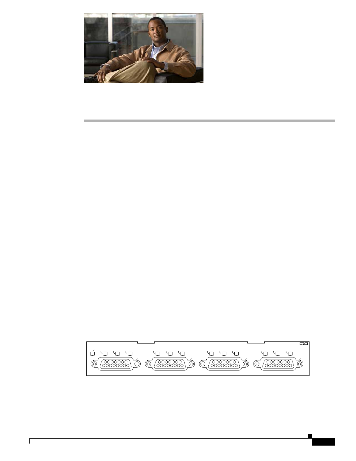
The P A-4E1G, sho wn in Figure 1-1 and Figure 1-2, provides up to four E1 synchronous serial interfaces,
which are compatible with and specified by G.703/G.704. The PA-4E1G network interfaces provide a
connection between standard serial interfaces such as V.35 to telephone lines or Post, Telephone, and
Telegraph (PTT) networks. Each PA-4E1G interface operates in full-duplex mode at E1 (2.048 Mbps)
speed.
The PA-4E1G interfaces do not operate in the data terminal equipment (DTE) and data communications
equipment (DCE) modes that are typical of data communications interfaces. The PA-4E1G interfaces
operate with either a line-recovered or an internal clock signal. The def ault is fo r a line clock si gnal th at
the interface recovers from the received data stream. The interface can also operate with an internal clock
signal. The PA-4E1G generates the internal clock signal; the interface does not use the motherboard or
system clock.
CHAPTER
1
OL-3065-05
Figure 1-1 PA-4E1G—75-Ohm, Unbalanced (Front Panel View)
EN
LB
LA
RA
LB
LA
RA
0
PA-4E1G Serial Port Adapter Installation and Configuration
LB
LA
RA
1
2
E1 G.703/G.704-75 OHM
LB
LA
RA
3
H9600
1-1
Page 14
Interface Specifications
Chapter 1 Overview
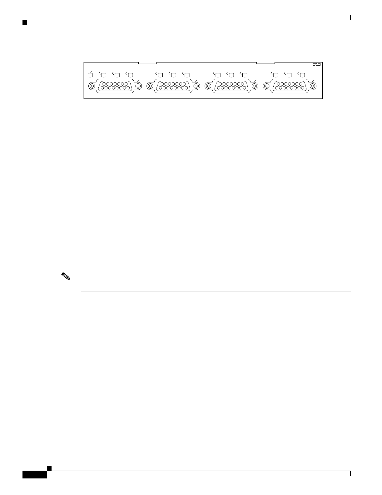
Figure 1-2 PA-4E1G—120-Ohm, Balanced (Front Panel View)
Features
EN
LB
LA
RA
LB
LA
RA
0
LB
LA
RA
1
2
E1 G.703/G.704-120 OHM
LB
LA
RA
3
H9607
The PA-4E 1G provides the following features and capabilities:
• Provides framed and unframed service access, E1 (2.048 Mbps) line speeds over unbalanced 75-ohm
or balanced 120-ohm cable, with 15-pin, D-shell (DB-15) receptacles on the port adapter
• Operates over E1 leased-line services, and provides ITU-T G.703 with high-density bipolar of order
3 (HDB3) line encoding
• Operates with either an external or internal clock signal, and runs at wire speed
• Provides for local and remote loopback testing services
• Allows you to fractionalize a data stream into a single channel from 64 kilobits per second (kbps)
to 1984 kbps
• Provides G.704 framing for n x 64-kbps service support (where n = 1 to 31)
• Support for 4-bit cyclic redundancy check (CRC4) to provide and ensure data integrity
• Support for point-to-point connections to supported platforms
• Eliminates the need for a separate, external data termination unit that is typically used to convert
standard serial interfaces, such as V.35, to E1-G.703/G.704
Note PA-4E 1Gs are available as spare parts PA-4E1G-120(=) and PA-4E1G-75(=).
Interface Specifications
Each PA-4E1G interface is available in either balanced (120-ohm) or unbalanced (75-ohm) mode; a
unique port adapter supports each type. Neither the balanced and unbalanced modes nor the balanced
and unbalanced cables are interchangeable; you cannot configure a balanced port to support an
unbalanced line, nor can you attach an interface cable intended for a balanced line to an unbalanced port.
Balanced interfaces typically use three conductors and three signal states: high, low, and ground. The
high and low signals mirror each other. Unbalanced interfaces use only two signals: signal and ground.
You can discover the mode of each interface by examining the agency approval label on each port
adapter, or by using the show controller cbus command.
Following is an example of discovering whether the PA-4E1G is in balanced or unbalanced mode:
Router# show controllers cbus
Serial1/1/0, applique is G.703 Unbalanced
[remainder of displayed text omitted from example]
Serial1/1/1, applique is G.703 Unbalanced
[remainder of displayed text omitted from example]
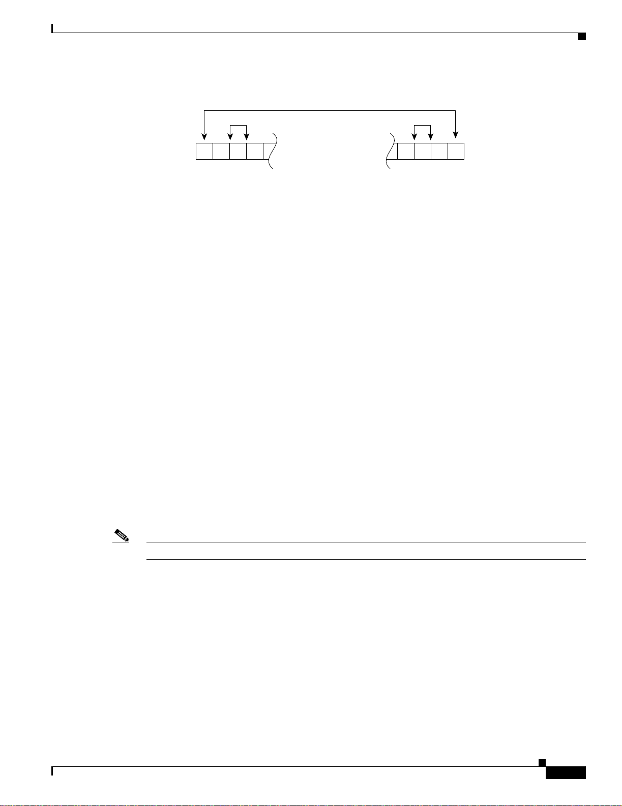
The PA-4E1G interface is divided into 32 time slots or frames. (See Figure 1-3.)
1-2
PA-4E1G Serial Port Adapter Installation and Configuration
OL-3065-05
Page 15
Chapter 1 Overview
Figure 1-3 Time Slot Diagram
2,048 Mbps
64 kbps 8 bits
32 time slots = 256 bits
Interface Specifications
Time slot
0 1 2 3 29303128
H2402
Each of the 32 time slots is an 8-bit frame that transmits data at 64 kbps. Each of these time slots can be
configured to carry data or to remain empty. (The P A-4E1G inserts an idle pattern i nto empty time slots.)
Time slot 0, or the first 8 bits, is reserved as overhead. The remaining 248 bits (31 frames with 8 bits
each) are designated time slots 1 through 31. Time slot 16 is also designated as a framing slot when usi ng
framed mode. When you use framed mode (G.704), you can configure time slot 16 to carry data and
operate as any of the other slots; therefore, in framed mode time slot 0 must be designated as a framing
signal; time slot 16 can be configured for either data or framing.
With framed mode (G.704) you can specify a bandwidth for the interface by designating 31 of the time
slots for data and reserving time slot 0 for framing (timing). When you use framed mode, you must
designate start and stop time slots; the slots within the start and stop boundaries are used for data, and
the remaining slots are left idle. For example, on an interface with framing set on time slots 1 through
8, the interface carries data within the specif ied 8 frames, and frames 9 through 31 remain idle. Because
each time slot transmits at 64 kbps, the interface operates at 512 kbps (8 frames x 64 kbps = 512 kbps).
By configuring 16 of the time slots to carry data and the other 16 to remain empty, you can essentially
configure the interface for 1.024 Mbps (by leaving half the time slots empty and unable to carry data).
The system inserts an idle pattern into unused time slots to identify them as overhead (unused for data).
Only one contiguous time slot range can be used. In Private A utomatic Branch Exchange (PABX)
systems, time slot 16 is always left unused. By default, time slot 16 is not enabled for data in the
PA-4E1G interface. The command ts16 overrides the default and enables time slot 16 to carry data.
Unframed mode (G.703) uses all 32 time slots for data. None of the 32 time slots are used for framing
signals. This allows each of the 32 time slots to transmit at 64 kbps; therefore, 32 time slots x 64 kbps =
2.048 Mbps. While unframed mode is the default, you can also specify unframed mode with the
command timeslot 0-0, which specifies time slot 0 as the start slot with no stop (ending) time slot;
therefore, all slots are used for data. The no timeslot command restores the default of unframed mode.
OL-3065-05
Framed mode supports a 4-bit cyclic redundancy check (CRC4), which you enable with a software
command. The default is for no CRC.
Note The E1-G.703/G.704 interface on PA-4E1G is compliant with BABT 221.
For more information about CRC4 with a PA-4E1G on a VIP , Cisco 7100 series router, Cisco 7200 series
router, or Cisco uBR7200 series router, refer to Chapter 4, “Configuring the PA-4E1G.”
PA-4E1G Serial Port Adapter Installation and Configuration
1-3
Page 16
LEDs
LEDs
Chapter 1 Overview
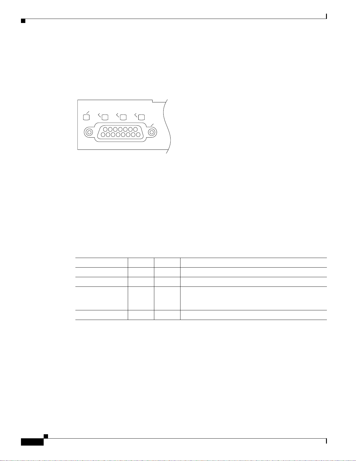
The P A-4E1G has one row of three status LEDs for each port and one EN ABLED LED. (See Figure 1-4.)
The green- and amber-colored LED for each port indicates port status.
Figure 1-4 PA-4E1G LEDs—Partial Front-Panel View
EN
LB
LA
RA
0
H9602
After system initialization, the ENABLED LED goes on to indicate that the port adapter has been
enabled for operation.
The following conditions must be met before the PA-4E1G is enabled:
• The PA-4E1G is correctly connected and receiving power.
• A valid system software image for the port adapter has been downloaded successfully.
• The system recognizes the PA-4E1G or a VIP with a PA-4E1G.
If any of the above con ditions are not met , or if the initializati on fails for oth er reasons, the enabled LED
does not go on.
Table 1-1 lists port LED colors and indications.
Table 1-1 PA-4E1G LEDs
LED Label Color State Meaning
Enabled (EN) Green On Port adapter is enabled for operation.
Loopback (LB) Amber On Line or local loopback is active.
Local alarm (LA) Amber On A loss of signal (LOS), a loss of frame (LOF), an alarm
Remote alarm (RA) Amber On A remote source indicates an error on its incoming signal.
Cables, Connectors, and Pinouts
This section describes the port adapter cables for data communications and the PA-4E1G interfaces.
Each PA-4E1G provides up to four 15-pin, D-shell (DB-15) receptacles, which support only
E1-G.703/G.704 interfaces.
The P A-4E1Gs use a DB-15 receptacle for both the balanced and unbalanced ports. The label on the port
adapter indicates if the ports on that port adapter are 75-ohm or 120-ohm. (See Figure 1-1 and
Figure 1-2.)
indication signal (AIS), or any combination of these is
detected.
1-4
PA-4E1G Serial Port Adapter Installation and Configuration
OL-3065-05
Page 17
Chapter 1 Overview
Note You must connect the correct type of interface cable for the port to operate.
Cables, Connectors, and Pinouts
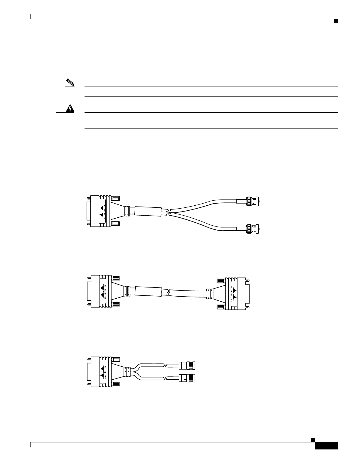
The port adapter end of all E1-G.703/G.704 adapter cables is a DB-15 connector. At the network end,
the adapter cable for unbalanced (75-ohm) connections uses a BNC connector. The adapter cables for
balanced (120-ohm) connections u se DB-15, tw inaxial, or RJ-45 connections to accommodate
connection standards in different countries.
Warning
It is a requirement of the statutory approval of the E1-G.703/G.704 interface that the jackscrews of the
connector backshell are securely screwed down while the portadapter is operating.
Cables for balanced and unbalanced mode are available with the following types of network-end
connectors:
• Unbalanced (75-ohm) coaxial cables with BNC connectors at the network end, which are used
primarily for connection in the United Kingdom. (See Figure 1-5.)
Figure 1-5 E1-G.703/G.704 Interface Cable for Unbalanced Connections—with BNC Connectors
and Coaxial Cables
H2421
• Balanced (120-ohm) cable with a DB-15 connector at the network end. (See Figure 1-6.)
Figure 1-6 E1-G.703/G.704 Interf ace Cable for Balanced Connections—with DB-15 Connectors on
Both Ends
OL-3065-05
H2476
Balanced (120-ohm) twi naxial sp lit cab le (with separate transmit and receive cables), each with a
•
twinaxial connector. (See Figure 1-7.)
Figure 1-7 E1-G.703/G.704 Interface Cable for Balanced Connections—with Twinaxial
Connectors and Cables
H2424
PA-4E1G Serial Port Adapter Installation and Configuration
1-5
Page 18

Cables, Connectors, and Pinouts
Cable Product Numbers
Table 1-2 lists the product numbers and descriptions of the E1-G.703/G.704 cables.
Table 1-2 Product Numbers and Descriptions of E1-G.703/G.704 Port Adapter Cables
Cable Product Numbers Description
CAB-E1-TWINAX(=)
CAB-E1-DB15(=) E1 cable, DB-15, 120-ohm, balanced, 5 m
CAB-E1-BNC(=) E1 cable, BNC, 75-ohm, unbalanced, 5 m
1. The appended equal sign (=) indicates a spare part.
Cable Distance Limitations
Unbalanced G.703 interfaces allow for a longer maximum cabl e length than those specif ied for balanced
circuits. Table 1-3 lists the maximum cable lengths for each E1-G.703/G.704 cable type by the
connector used at the network (non-port ada pter) end.
Chapter 1 Overview
1
E1 cable, twinaxial, 120-ohm, bala nced, 5 m
Table 1-3 E1-G.703/G.704 Maximum Cable Lengths
Connection Type BNC Twinaxial
Balanced – 300 m
Unbalanced 600 m –
1-6
PA-4E1G Serial Port Adapter Installation and Configuration
OL-3065-05
Page 19
Chapter 1 Overview
E1-G.703/G.704 Port Adapter Cable Pinouts
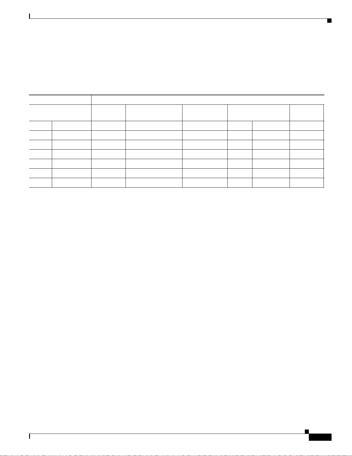
Table 1-4 shows the signal pinouts for each type of E1-G.703/G.704 interface cable. All cables use a
DB-15 connector at the port adapter end.
Table 1-4 E1-G.703/G.704 Port Adapter Cable Connector Pinouts
Port Adapter End Network End
Port Adapter Slot Locations on the Supported Platforms
1
DB-15
Pin Signal
4
DB-15
2
DB-15 (Null Modem) Twinaxial
2
RJ-45
2
BNC
Pin Pin Signal Pin Signal Signal
9 Tx tip 1 3 Rx tip 4 Rx tip Tip
2 Tx ring 9 11 Rx ring 5 Rx ring Shield
10 Tx shield 2 4 Rx shield 6 Rx shield –
8 Rx tip 3 1 Tx tip 1 Tx tip Tip
15 Rx ring 11 9 Tx ring 2 Tx ring Shield
7 Rx shield 4 2 Tx shield 3 Tx shield –
1. Any pins not described in this table are not connected.
2. 120-ohm, balanced cable
3. 75-ohm, unbalanced cable
4. Tx = transmit, Rx = receive
Port Adapter Slot Locations on the Supported Platforms
This section discusses port adapter slot locations on the supported platforms. The illustrations that
follow summarize slot location conventions on each platform:
• Cisco 700 0 Series Ro uters VIP Slot Numberi ng, page 1-8
• Cisco 710 0 Series Ro uters Slot Num bering, pa ge 1-10
• Cisco 720 0 Series Ro uters and Cisco 7200 VXR Routers Slot Numbering, page 1-11
3
OL-3065-05
• Cisco uBR7200 Series Router Slot Numbering, page 1-14
• Cisco 7 201 Router Slo t Numbe ring, page 1 -16
• Cisco 7301 Router Slot Numbering, page 1-16
• Cisco 7304 PCI Port Adapter Carrier Card Slot Numbering, page 1-17
• Cisco 7401ASR Router Slot Numbering, page 1-18
• Cisco 750 0 Series Ro uters VIP Slot Numberi ng, page 1-18
PA-4E1G Serial Port Adapter Installation and Configuration
1-7
Page 20
Port Adapter Slot Locations on the Supported Platforms
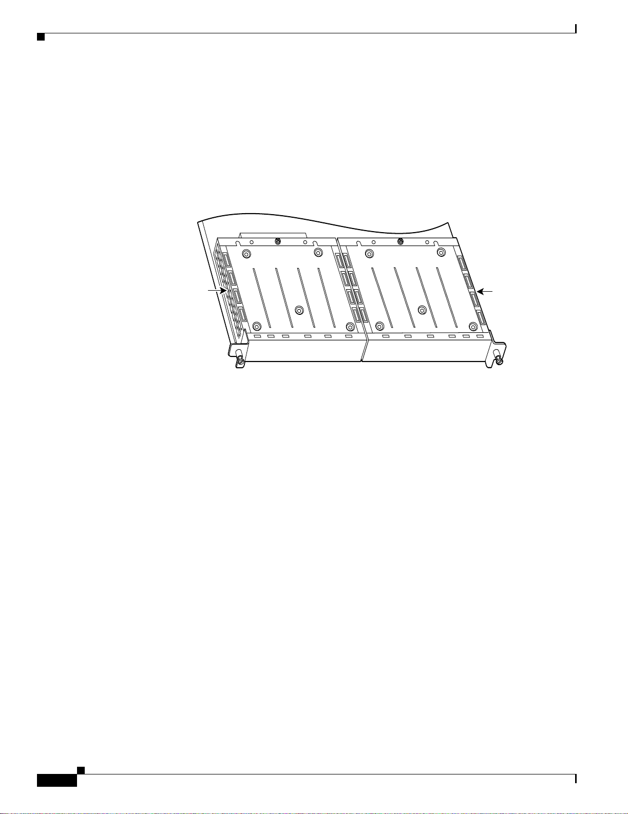
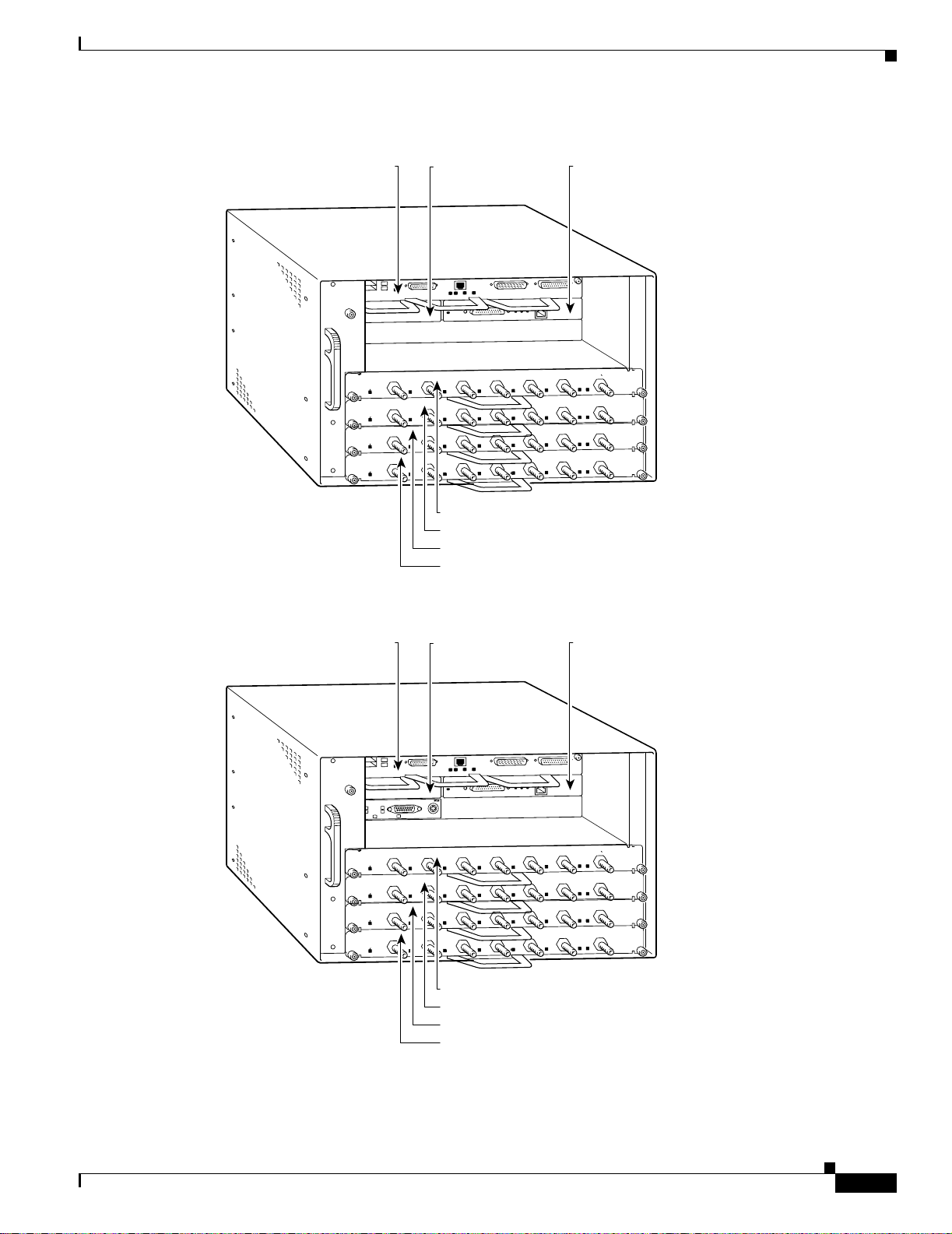
Cisco 7000 Series Routers VIP Slot Numbering
Port adapters are supported on the VIPs (versatile interface processors) used in Cisco 7000 series routers.
In the Cisco 7000 router, the VIP motherboard is installed vertically in the VIP slot.In the Cisco 7010
router, the VIP motherboard is installed horizontally in the VIP slot. A port adapter can be installed in
either bay (port adapter slot 0 or 1) on the VIP. The bays are numbered from left to right on the VIP.
Figure 1-8 shows the slot numbering of a VIP.
Figure 1-8 VIP Slot Locations
Chapter 1 Overview
ort adapter slot 0
Port adapter
handles not
shown
Port adapter slot 1
29328
1-8
PA-4E1G Serial Port Adapter Installation and Configuration
OL-3065-05
Page 21
Chapter 1 Overview
Port Adapter Slot Locations on the Supported Platforms
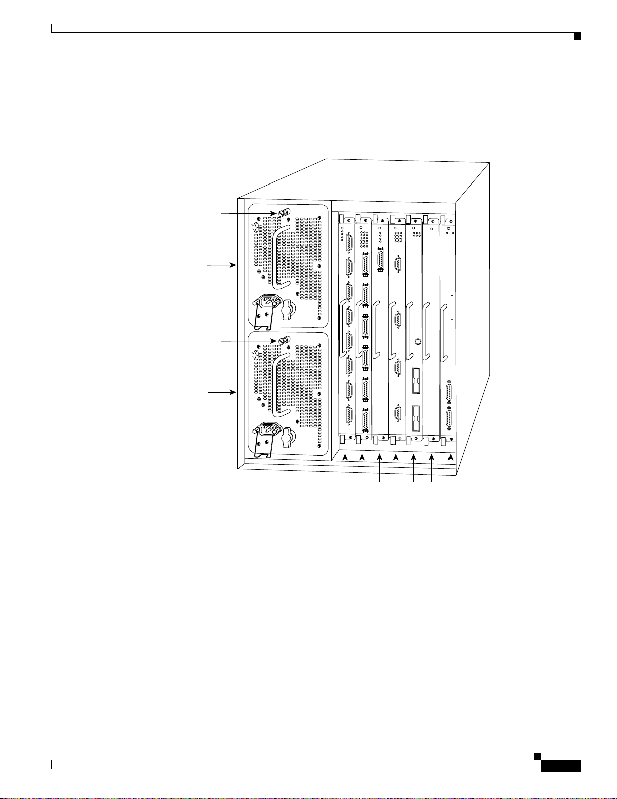
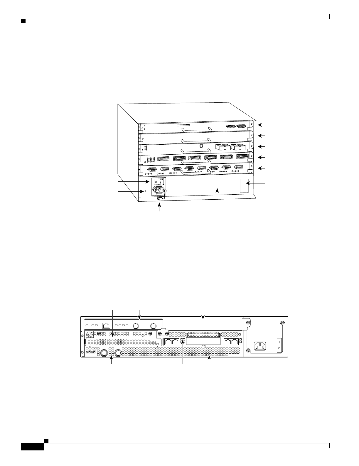
Cisco 700 0 rou ter s have five slots for port adapters, and two slots for Route Switch Proce ssors (RSPs).
The slots are numbered from left to right. You can place a port adapter in any of the VIP interface slots
(slot 0 through 4). Figure 1-9 shows the slot numbering on a Cisco 7000 router.
Figure 1-9 VIP Slots in the Cisco 7000 Router
Captive
installation screw
Upper
power supply
DC FAIL
AC POWER
I
O
Captive
installation screw
Lower
power supply
DC FAIL
AC POWER
H2358
I
O
Slot 0
2
1
3 4 SP
or
RP
slot
SSP
slot
OL-3065-05
PA-4E1G Serial Port Adapter Installation and Configuration
1-9
Page 22
Port Adapter Slot Locations on the Supported Platforms
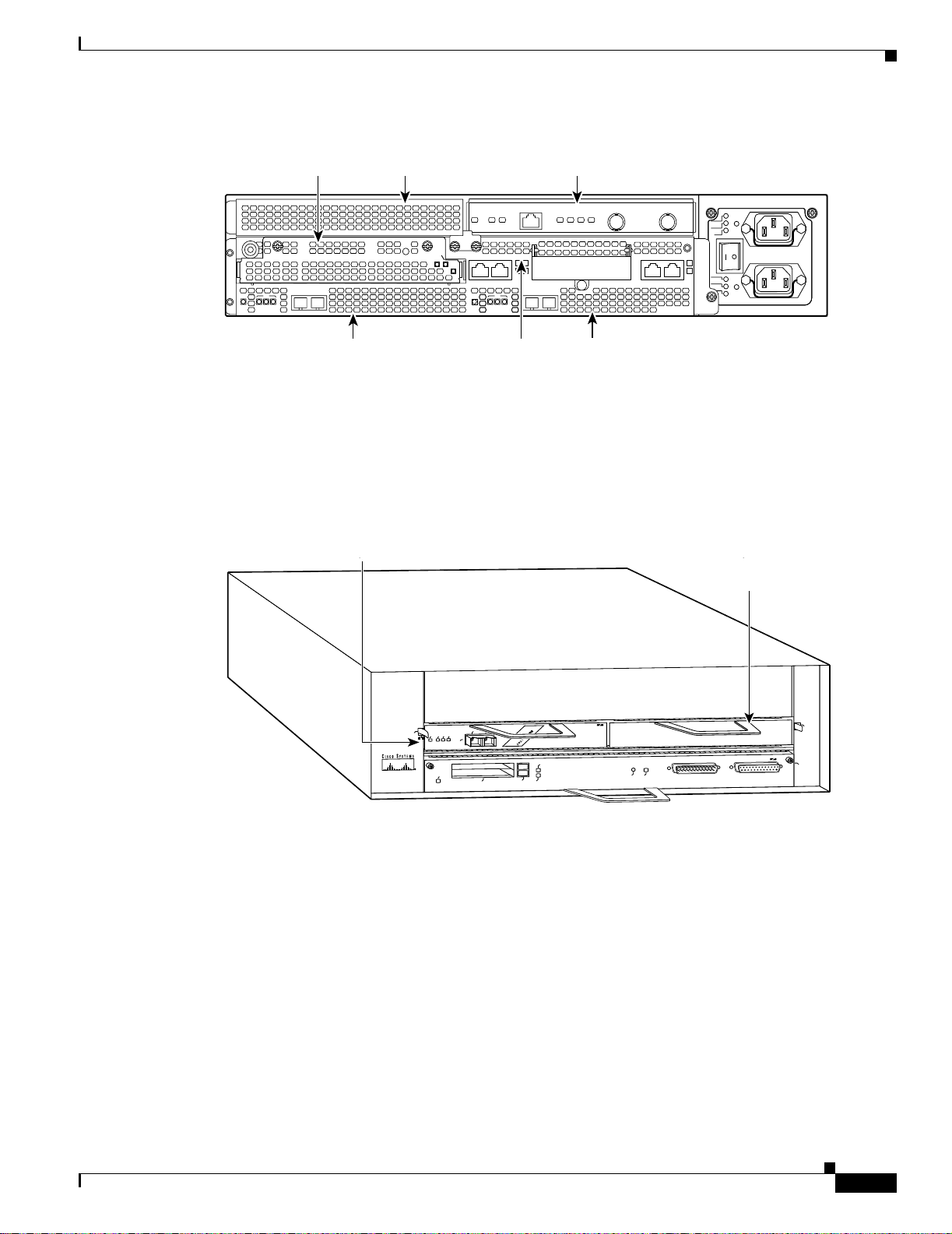
Cisco 7010 routers have three slots for port adapters, and two slots for Route Switch Processors (RSPs).
The slots are numbered from bottom to top. You can place a port adapter in any of the VIP interface slots
(slot 0 through 2). Slots 3 and 4 are alw a ys reserved for RSPs. Figure 1-10 shows the slot numbering on
a Cisco 7010 router.
Figure 1-10 VIP Slots in the Cisco 7010 Router
Chapter 1 Overview
RP slot
SP or SSP slot
Interface processor slot 2
Interface processor slot 1
Interface processor slot 0
Power switch
Chassis ground
screw
Power receptacle
Cisco 7100 Series Routers Slot Numbering
Port adapters can be installed in port adapter slot 3 in Cisco 7120 series routers, and in port adapter slot 4
in Cisco 7140 series routers. Figure 1-11 shows the slot numbering on a Cisco 7120 series router.
Figure 1-12 shows the slot numbering on a Cisco 7140 series router.
Figure 1-11 Port Adapter Slots in the Cisco 7120 Series Router
Slot 3
ACT
5
I
EN
RX
CEL CAR ALM
E3
RXTX
FE 0 / 0 FE
ACT
LNK0LNK
1
0 / 1
Slot 4Slot 5
AC-input power supply
SLOT 0 SLOT 1
CONS
PWR
SYS
RDY
AUX
7120 - AE3
DC OK LED
H2359
0
2
18498
1-10
Slot 1
PA-4E1G Serial Port Adapter Installation and Configuration
Slot 0
Slot 2
OL-3065-05
Page 23
Chapter 1 Overview
p
p
Port Adapter Slot Locations on the Supported Platforms
Figure 1-12 Port Adapter Slots in the Cisco 7140 Series Router
Slot 4Slot 5 Slot 3
TX
SLOT 0 SLOT 1
CONS
BOOT
ERROR
5
155 - MM
RX
RX
I
EN
CEL CAR ALM
TX
RESETSM-ISM
EN
FE 0 / 0 FE
EN
CEL CAR ALM
ACT
ACT
LNK0LNK
1
0 / 1
155 - MM
RX
RX
PWR
SYS
RDY
AUX
7140 - 2MM3
K
O
A
C
K
C
O
D
T
F
O
0
A
K
C
O
K
C
O
D
O
T
F
2
18499
Slot 1
Slot 0
Slot 2
Cisco 7200 Series Routers and Cisco 7200 VXR Routers Slot Numbering
Cisco 7202 routers have two por t adapter sl ots. The sl ot s are numbered f rom l eft to right. You can place
a port adapter in either of the slots (slot 1 or slot 2). Figure 1-13 shows the slot numbering on a
Cisco 720 2 router.
Figure 1-13 Port Adapter Slots in the Cisco 7202 Router
(blank port
adapter installed)
Cisco 7200
D
E
L
B
A
N
RX CELLS
E
1
E
A
N
RX CARRIER
D
E
L
B
RX ALARM
TX
RX
155-SMI
C
P
PRODUCTO LASER CLASS 1
PROUIT LASER DE CLASSE 1
CLASS 1 LASER PRODUCT
LASERPRODUKT DER KLASSE 1
T
C
IA
E
C
J
M
E
ENHANCED ATM
1
T
O
L
S
0
T
O
L
S
CPU RESET
1O POWER
OK
FAST ETHERNET INPUT/OUTPUT CONTROLLER
SERIES
0
2
11603
OL-3065-05
PA-4E1G Serial Port Adapter Installation and Configuration
1-11
Page 24

Port Adapter Slot Locations on the Supported Platforms
Cisco 7204 routers and Cisco 7204VXR routers have four slots for port adapters, and one slot for an
input/output (I/O) controller. The slots are numbered from the lower left to the upper right, beginning
with slot 1 and continuing through slot 4. You can place a port adapter in any of the slots (slot 1 through
slot 4). Slot 0 is always reserved for the I/O controller. Figure 1-14 sho ws the slot numbering on a Cisco
7204 router. The Cisco 7204VXR router is not shown.
Figure 1-14 Port Adapter Slots in the Cisco 7204 Router
Chapter 1 Overview
Port adapter slot 4
Port adapter slot 2
Blank port adapter
Port adapter slot 3
Port adapter slot 1
Cisco 7200
ETHERNET 10BT
FAST SERIAL
D
R
II
M
E
F
ED
BL
A
N
E
N
E
D
C
B
C
L
R
X
X
T
R
0
RJ-45
MII
RJ45
RJ45
EN
OK
EN
1O PWR
LINK
X
X
T
R
1
CPU RESET
II
M
0
X
R
2
FAST ETHERNET INPUT/OUTPUT CONTROLLER
K
D
0
E
L
B
A
3
N
E
N
E
C
D
T
T
1
L
B
A
N
E
3
2
1
C
B
D
L
R
R
D
E
IN
L
3
1
2
0
C
D
D
C
B
D
C
D
C
C
P
T
C
L
R
R
T
T
T
C
IA
E
C
J
M
E
D
D
C
B
D
C
D
T
T
C
L
R
R
T
1
T
O
L
S
0
T
O
L
S
SERIES
4
J
IN
R
L
X
X
X
T
R
T
3
ETHERNET-10BFL
X
R
4
4
X
T
2
FAST ETHERNET
5
K
0
H7399
Port adapter slot 0
1-12
PA-4E1G Serial Port Adapter Installation and Configuration
OL-3065-05
Page 25
Chapter 1 Overview
Port Adapter Slot Locations on the Supported Platforms
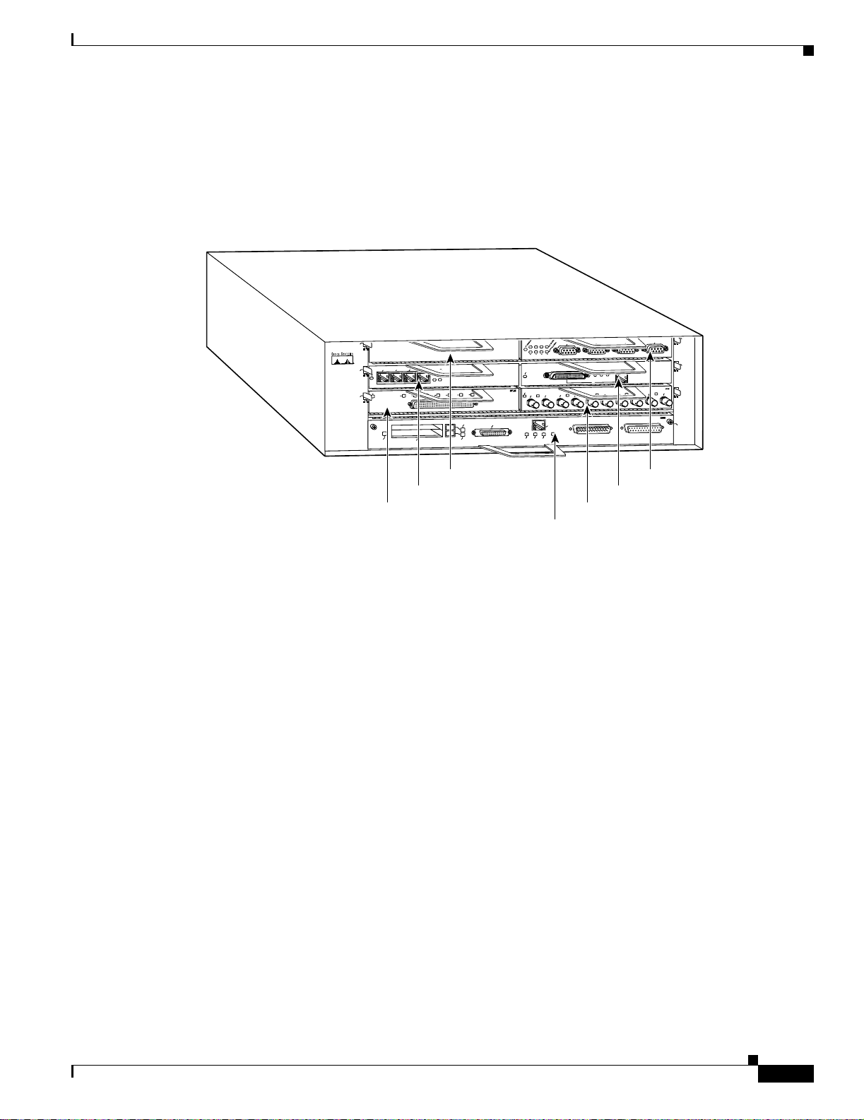
Cisco 7206 routers and Cisco 7206VXR routers have six slots for port adapters, and one slot for an
input/output (I/O) controller. The slots are numbered from the lower left to the upper right, beginning
with slot 1 and continuing through slot 6. You can place a port adapter in any of the six slots (slot 1
through slot 6). Slot 0 is always reserved for the I/O controller. Figure 1-15 shows the slot numbering
on a Cisco 7206 router. The Cisco 7206VXR router is not shown.
Figure 1-15 Port Adapter Slots in the Cisco 7206 Router
G
IN
R
N
E
K
O
T
6
3
2
1
0
D
E
L
B
A
N
E
N
E
X
X
R
TX
R
0
RJ-45
RJ-45
RJ-45
EN
1O PWR
OK
LINK
X
T
1
K
II
LIN
M
0
X
X
T
R
2
FAST ETHERNET INPUT/OUTPUT CONTROLLER
FAST ETHERNET
ETHERNET-10BFL
X
R
4
TX
2
4
J45
R
X
X
T
R
3
0
28329
Cisco 7200
Series
5
T
B
10
T
E
N
R
E
H
T
K
D
E
L
B
A
3
N
E
EN
1
ENABLED
3
2
N
1
0
I
L
3
1
2
0
4
3
2
1
0
EJECT
PCMCIA
E
5
.3
-V
L
IA
ER
S
7
6
5
SLOT 1
FE MII
MII
SLOT 0
EN
Port adapter slot 5
Port adapter slot 3
Port adapter slot 1
Port adapter slot 6
Port adapter slot 4
Port adapter slot 2
Port adapter slot 0
OL-3065-05
PA-4E1G Serial Port Adapter Installation and Configuration
1-13
Page 26
Port Adapter Slot Locations on the Supported Platforms
Cisco uBR7200 Series Router Slot Numbering
The Cisco uBR7223 router has one port adapter slot (slot 1). Slot 0 is always reserved for the I/O
controller—if present. Figure 1-16 shows the slot numbering of port adapters on a Cisco uBR7223
router.
The Cisco uBR7246 router and Cisco uBR7246VXR router have two port adapter slots (slot1 and slot
2). Slot 0 is always reserved for the I/O controller—if present. Figure 1-17 shows the slot numbering of
port adapters on a Cisco uBR7246 router. Figure 1-18 shows the slot numbering of port adapters on a
Cisco uBR7246VXR router.
Figure 1-16 Port Adapter Slots in the Cisco uBR7233 Router
Port adapter slot 0
(I/O controller)
Chapter 1 Overview
Port adapter slot 1
uBR - MCI6
5
4
3
2
1
0
US
US
ENABLED
1
0
US
US
ENABLED
US
US
2
US
US
US
US
5
uBR - MCI6
DS
DS
Cable modem card slot 2
Cable modem card slot 3
15745
1-14
PA-4E1G Serial Port Adapter Installation and Configuration
OL-3065-05
Page 27
Chapter 1 Overview
uBR - CLK-T1
FREERUN
FAULT
LOS
SEC
ACTIVE
Port Adapter Slot Locations on the Supported Platforms
Figure 1-1 7 Port Adapter Slots in the Cisco uBR7246 Router
Port adapter slot 0
(I/O controller)
ENABLED
ENABLED
ENABLED
ENABLED
0
US
0
US
0
US
0
US
Port adapter slot 1
(blank)
3
2
1
US
1
US
1
US
1
US
US
US
2
US
2
US
2
US
Port adapter slot 2
CI6
uBR - M
5
4
US
US
US
US
US
5
5
5
uBR - M
uBR - MCI6
uBR - MCI6
DS
CI6
DS
DS
DS
Cable modem card slot 3
Cable modem card slot 4
Cable modem card slot 5
Cable modem card slot 6
Figure 1-18 Port Adapter Slots in the Cisco uBR7246VXR Router
H11323
Port adapter slot 0
(I/O controller)
ENABLED
ENABLED
ENABLED
ENABLED
Port adapter slot 1
Port adapter slot 2
(blank)
0
US
US
1
0
US
US
1
0
US
US
1
0
US
US
US
US
2
US
2
US
2
US
US
US
US
US
US
5
5
5
uBR - MCI6
uBR - MCI6
uBR - MCI6
DS
DS
DS
DS
uBR - MCI6
5
4
3
2
1
31501
Line card slot 3
Line card slot 4
Line card slot 5
Line card slot 6
PA-4E1G Serial Port Adapter Installation and Configuration
OL-3065-05
1-15
Page 28

Port Adapter Slot Locations on the Supported Platforms
Cisco 7201 Router Slot Numbering
Figure 1-19 shows the front view of a Cisco 7201 router with a port adapter installed. There is only one
port adapter slot (slot 1) in a Cisco 7201 router.
Figure 1-19 Port Adapter Slot in the Cisco 7201 Router
Port adapter slot
ENABLED
RX CELLS
RX CARRIER
RX ALARM
A
T
M
Cisco
7201
RJ45
EN
LINK/AC
TV
SFP
RJ45
PA
SLOT
1
EN
GE 0/0
G
E 0/1
Chapter 1 Overview
LINK/AC
TX
CONSOLE
TV
LINK/ACTV
SFP
R
X
LINK/ACTV
SFP
TX
SFP
RX
MNG
MNT US
GE 0/2
E ONLY
G
E 0/3
AUX
FE
0/0
0
FE
LINK
COMPACT FLASH
ALA
RM
P
WR OK
STATUS
CF
ACTV
230308
Cisco 7301 Router Slot Numbering
Figure 1-20 shows the front view of a Cisco 7301 router with a port adapter installed. There is only one
port adapt er slot (slot 1) in a Ci sco 7301 router.
Figure 1-20 Cisco 7301 Router with a Port Adapter Installed
Port adapter slot
ENABLED
RX CELLS
RX CARRIER
RX ALARM
A
T
M
GIGABIT ETHERNET 0/0
SLOT 1
RJ45 EN
GIGABIT ETHERNET 0/1
LINK
RJ45 EN
TX RX
GBIC
LINK
TX RX
GBIC
CISCO 7400
SERIES
C
IS
C
O
7411
GIGABIT ETHERNET 0/2
RJ45 EN
TX RX
LINK
AUX
CONSOLE
GBIC
COMPACT
FLASH
100-240V, 2A, 50/60 Hz
24V
=
9A, 48 - 60V
=
ALARM
STATUS
5A
84988
1-16
PA-4E1G Serial Port Adapter Installation and Configuration
OL-3065-05
Page 29

Chapter 1 Overview
Port Adapter Slot Locations on the Supported Platforms
Cisco 7304 PCI Port Adapter Carrier Card Slot Numbering
The Cisco 7304 PCI Port Adapter Carrier Card installs in Cisco 7304 router module slots 2 through 5.
Figure 1-21 shows a Cisco 7304 PCI Port Adapter Carrier Card with a port adapter installed. The
Cisco 7304 PCI Port Adapter Carrier Card accepts one single-width port adapter.
Figure 1-22 shows the module slot numbering on a Cisco 7304 router. The port adapter slot number is
the same as the module slot number. Slot 0 and slot 1 are reserved for the NPE module or NSE module.
Figure 1-21 Cisco 7304 PCI Port Adapter Carrier Card—Port Adapter Installed
7300-CC-PA
ENABLED
RX CELLS
RX CARRIER
RX ALARM
OIR
STATUS
7300 PA C
AR
RIER
ATM
84653
Figure 1-22 Module Slots on the Cisco 7304 Router
Slot 4
7300-2O
C
3ATM
-M
M
TX
0RX
O
IR
STATUS
2-PORT OC3 ATM MM
9K
-1
0C
4
8
OIR
STATUS
1
-P
O
R
T
O
C
4
8
P
O
S
C
A
R
A
w
/ S
M
S
R
T
X
R
IE
R
/
L
A
R
M
1RX
A
C
T
IV
E
/
LO
O
P
B
A
C
C
K
A
R
R
IE
R
/
A
LA
R
M
A
C
T
IV
E
/
L
O
O
P
B
A
C
K
T
X
R
X
9K
-40
C
3/P
O
S
-M
M
OIR
OIR
STATUS
STATUS
4
-P
O
R
T
O
C
0
3
P
O
S
w
/ M
1
M
CARRIER/
ALARM
Slot 0
Slot 2
2
3
Slot 3
ACTIVE/
LOOPBACK
Slot 5
70550
Slot 1
OL-3065-05
PA-4E1G Serial Port Adapter Installation and Configuration
1-17
Page 30

Port Adapter Slot Locations on the Supported Platforms
Cisco 7401ASR Router Slot Numbering
Figure 1-23 shows the front view of a Cisco 7401ASR router with a port adapter installed. There is only
one port adapter slot (slot 1) in a Cisco 7401ASR router.
Figure 1-23 Port Adapter Slot in the Cisco 7401ASR Router
Chapter 1 Overview
ENABLED
RX CELLS
RX CARRIER
RX ALARM
TX
RX
ENHANCED ATM
Cisco 7500 Series Routers VIP Slot Numbering
Port adapters are supported on the VIPs (versatile interface processors) used in Cisco 7500 series
routers. In the Cisco 7505 router, the VIP motherboard is installed horizontally in the VIP slot. In the
Cisco 7507 router and Cisco 7513 router, the VIP motherboard is installed vertically in the VIP slot. A
port adapter can be installed in either bay (port adapter slot 0 or 1) on the VIP. The bays are numbered
from left to right on the VIP. Figure 1-24 shows the slot numbering on a VIP.
Figure 1-24 VIP Slot Locations
57680
1-18
Port adapter slot 0
Port adapter
handles not
shown
PA-4E1G Serial Port Adapter Installation and Configuration
Port adapter slot 1
29328
OL-3065-05
Page 31

Chapter 1 Overview
Identifying Interface Addresses
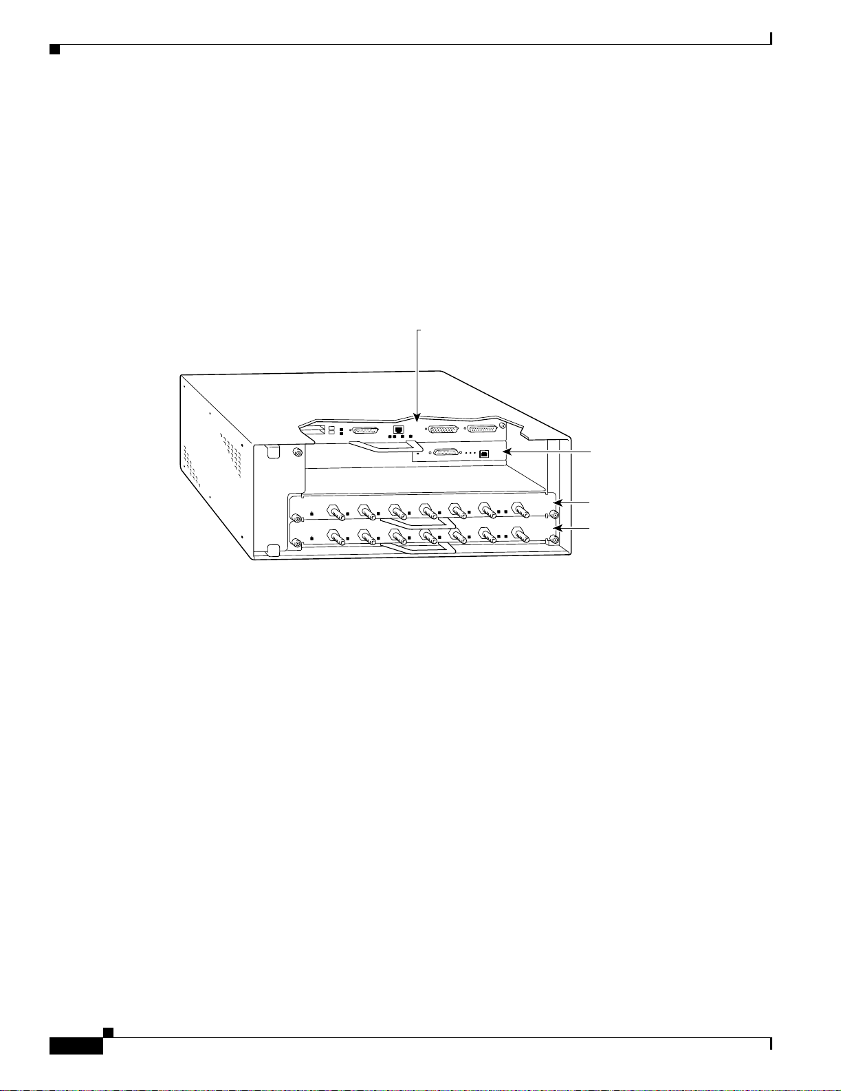
Cisco 7505 routers have four slots for port adapters, and one slot for an RSP. The slots are numbered
from bottom to top. You can place a port adapter in any of the VIP interface slots (slot 0 through 3). One
slot is always reserved for the RSP. Figure 1-25 shows the slot numbering on a Cisco 7505 router.
Figure 1-25 VIP Slots in the Cisco 7505 Router
VIP in interface processor slot 3
R
SSO
CE
O
H PR
ITC
E SW
UT
T
L
A
T
C
1
T
JE
E
L
A
M
R
O
N
O
L
0
S
T
O
L
S
T
E
H
S
U
E
P
R
C
RO
E
L
O
S
N
O
C
Slot 3
Slot 2
Slot 1
Interface
processor
slots
Slot 0
29619
Cisco 7507 routers have f iv e slots for port adapte rs, and two slots for RSPs. The slots are numbered from
left to right. You can place a port adapter in any of the VIP interface slots (slot 0, 1, 4, 5, or 6). Slots 2
and 3 are always reserved for RSPs. The Cisco 7507 router is not shown.
Cisco 7513 routers have eleven slots for port adapters, and two slots for RSPs. The slots are numbered
from left to right. You can place a port adapter in any of the VIP interface slots (slots 0 through 5, or
slots 9 through 12). Slots 6 and 7 are always reserved for RSPs. The Cisco 7513 router is not shown.
Identifying Interface Addresses
This section describes how to identify interface addresses for the PA-4E1G in supported platforms.
Interface addresses specify the actual physical location of each interface on a router or switch.
Interfaces on a PA-4E1G installed in a router maintain the same address regardless of whether other port
adapters are installed or removed. However, when you move a port adapter to a different slot, the first
number in the interface address changes to reflect the new port adapter slot number.
Interfaces on a PA-4E1G installed in a VIP maintain the same address regardless of whether other
interface processors are installed or removed. However, when you move a VIP to a different slot, the
interface processor slot number changes to reflect the new interface processor slot.
OL-3065-05
PA-4E1G Serial Port Adapter Installation and Configuration
1-19
Page 32

Chapter 1 Overview
Identifying Interface Addresses
The following subsections describe the interface address formats for the supported platforms:
• Cisco 700 0 Series Ro uters VIP Interface Addresses, page 1-21
• Cisco 710 0 Series Ro uters Interface Addresse s, page 1-22
• Cisco 7200 Series Routers and Cisco 7200 VXR Routers Interface Addresses, page 1-22
• Cisco uBR7200 Series Routers Interface Addresses, page 1-22
• Cisco 7201 Router Interface Addresses, page 1-22
• Cisco 7301 Router Interface Addresses, page 1-23
• Cisco 7304 PCI Port Adapter Carrier Card Interface Addresses, page 1-23
• Cisco 7401ASR Router Interface Addresses, page 1-23
• Cisco 750 0 Series Ro uters VIP Interface Addresses, page 1-23
Table 1-5 summarizes the interface address formats for the supported platforms.
Table 1-5 Identifying Interface Addresses
Platform Interface Address Format Numbers Syntax
VIP in Cisco 7000 series
routers
Interface-processor-slot-number/port-adapter-slotnumber/interface-port-number
Interface processor slot—0
through 4 (depends on the
3/1/0
number of slots in the
router)
Port adapter slot— 0 or 1
Interface port—0 through 3
Cisco 7120 series router Port-adapter-slot-number/interface-port-number Port adapter slot—always 3
Interface port—0 through 3
Cisco 7140 series router Port-adapter-slot-number/interface-port-number Port adapter slot—always 4
Interface port—0 through 3
Cisco 7200 series routers
and Cisco 7200 VXR
routers (Cisco 7202,
Cisco 7204,
Cisco 7204VXR,
Port-adapter-slot-number/interface-port-number Port adapter slot—1 through
6 (depends on the number of
slots in the router)
1
Interface port—0 through 3
Cisco 7206,
Cisco 7206VXR)
Cisco 7201 router Port-adapter-slot-number/interface-port-number Port adapter slot—always 1
Interface port—0 through 3
Cisco uBR7223 router Port-adapter-slot-number/interface-port-number Port adapter slot—always 1
Interface port—0 through 3
Cisco uBR7246 and
Cisco uBR7246 VXR
routers
Port-adapter-slot-number/interface-port-number Port adapter slot—1 or 2
Interface port—0 through 3
1
Cisco 7301 routers Port-adapter-slot-number/interface-port-number Port adapter slot—always 1
3/1
4/0
1/0
1/0
1
1/0
1/0
1/0
1-20
Interface port—0 through 3
PA-4E1G Serial Port Adapter Installation and Configuration
OL-3065-05
Page 33

Chapter 1 Overview
Identifying Interface Addresses
Table 1-5 Identifying Interface A ddresses (continued)
Platform Interface Address Format Numbers Syntax
Cisco 7304 PCI Port
Adapter Carrier Card in
Cisco 7304 routers
Module-slot-number/interface-port-number Module slot—2 through 5
Interface port—0 through 3
Cisco 7401ASR routers Port-adapter-slot-number/interface-port-number Port adapter slot—always 1
3/0
1/0
Interface port—0 through 3
VIP in Cisco 7000 series or
Cisco 7500 series routers
Interface-processor-slot-number/port-adapter-slotnumber/interface-port-number
Interface processor slot—0
through 12 (depends on the
3/1/0
number of slots in the
router)
Port adapter slot—0 or 1
Interface port—0 through 3
1. Port adapter slot 0 is reserved for the Fast Ethernet port on the I/O controller (if present).
Cisco 7000 Series Routers VIP Interface Addresses
In Cisco 7000 series routers, port adapters are installed on a versatile interface processor (VIP), which
installs in interface processor slots 0 through 4 (depending on the number of slots in the router). The port
adapter can be installed in either bay (port adapter slot 0 or 1) on the VIP. See Figure 1-8, Figure 1-9,
and Figure 1-10
The interface address for the VIP is composed of a three-part number in the format
interface-processor-slot-number/port-adapter-slot-number/interface-port-number. See Table 1-5.
The first number identifies the slot in which the VIP is installed (slot 0 through 4, depending on the
number of slots in the router).
The second number identifies which bay on the VIP the port adapter is installed (0 or 1). The bays are
numbered from left to right on the VIP.
The third number identifies the physical port number (interface port number) on the port adapter. The
port numbers always begin at 0 and are numbered from left to right. The number of additional ports
depends on the number of ports on the port adapter. The PA-4E1G is a four-port port adapter, therefore
the port can be 0 through 3.
For example, if the four-port PA-4E1G is installed in a VIP in interface processor slot 3, port adapter
slot 1, the interface addresses would be 3/1/0, 3/1/1. 3/1/2, and 3/1/3 (interface processor slot 3, port
adapter slot 1, and interfaces 0,1, 2, and 3).
Note Although the processor slots in the 7-slot Cisco 7000 are vertically oriented and those in the 5-slot
Cisco 701 0 are horiz ontally orie nted, all Cisco 7000 series routers use the same met hod for proces sor
slot and interface port numbering.
OL-3065-05
PA-4E1G Serial Port Adapter Installation and Configuration
1-21
Page 34

Chapter 1 Overview
Identifying Interface Addresses
Cisco 7100 Series Routers Interface Addresses
In Cisco 7120 series router, port adapters are installed in port adapter slot 3. See Figure 1-11. In the
Cisco 7140 series router, port adapters are installed in port adapter slot 4. See Figure 1-12.
The interface address is composed of a two-part number in the format
port-adapter-slot-number/interface-port-number. See Table 1-5. For example, if a four-port PA-4E1G is
installed on a Cisco 7120 router, the interface addresses would be 3/0 through 3/3. If a four-port
PA-4E1G is installed on a Cisco 7140 router, the interface addresses would be 4/0 through 4/3.
Cisco 7200 Series Routers and Cisco 7200 VXR Routers Interface Addresses
In Cisco 7200 series routers and Cisco 7200 VXR routers, port adapter slots are numbered from the
lower left to the upper right, beginning with slot 1 and continuing through slot 2 for the Cisco 7202,
slot 4 for the Cisco 7204 and Cisco 7204VXR, and slot 6 for the Cisco 7206 and Cisco 7206VXR. Port
adapters can be installed in any available port adapter slot fro m 1 through 6 (d epending o n the numb er
of slots in the router). (Slot 0 is reserved for the I/O controller.) See Figure 1-13, Figure 1-14, and
Figure 1-15
The interface address is composed of a two-part number in the format
port-adapter-slot-number/interface-port-number. See Table 1-5. For example, if a four-port PA-4E1G is
installed in slot 1of a Cisco 7200 series route r, the interface addresses would be 1/0 through 1/3.
Cisco uBR7200 Series Routers Interface Addresses
In the Cisco uBR7223 router, only one slot accepts port adapters and it is numbered slot 1. See
Figure 1-16
In the Cisco uBR7246 router and Cisco uBR7246VXR router, port adapters can be installed in two port
adapter slots (slot1 and slot 2). Slot 0 is always reserved for the I/O controller—if present. See
Figure 1-17 and Figure 1-18.
The interface address is composed of a two-part number in the format
port-adapter-slot-number/interface-port-number. See Table 1-5. For example, if a four-port PA-4E1G is
installed in slot 1of a Cisco uBR7223 series router, the interface addresses would be 1/0 through 1/3. If
a four-port PA-4E1G is installed in slot 2 of a Cisco uBR7246 or Cisco uBR7246VXR router, the
interface addresses would be 2/0 through 2/3.
Cisco 7201 Router Interface Addresses
In the Cisco 7201 router, only one slot accepts port adapters and it is numbered as slot 1. See
Figure 1-19.
The interface address is composed of a two-part number in the format
port-adapter-slot-number/interface-port-number. See Table 1-5. For example, if a four-port P A-4E1G is
installed in a Cisco 7201 router, the interface addresses would be 1/0 through 1/3.
1-22
PA-4E1G Serial Port Adapter Installation and Configuration
OL-3065-05
Page 35

Chapter 1 Overview
Identifying Interface Addresses
Cisco 7301 Router Interface Addresses
In the Cisco 7301 router, only one slot accepts port adapters and it is numbered as slot 1. See
Figure 1-20.
The interface address is composed of a two-part number in the format
port-adapter-slot-number/interface-port-number. See Table 1-5. For example, if a four-port P A-4E1G is
installed in a Cisco 7301 router, the interface addresses would be 1/0 through 1/3.
Cisco 7304 PCI Port Adapter Carrier Card Interface Addresses
In the Cisco 7304 router, port adapters are installed in a Cisco 7304 PCI port adapter carrier card, which
installs in Cisco 7304 router module slots 2 through 5. The port adapter slot number is the same as the
module slot number. See Figure 1-21 and Figure 1-22.
The interface address is composed of a two-part number in the format
module-slot-number/interface-port-number. See Table 1-5. For example, if a four-port PA-4E1G is
installed in the Cisco 7304 PCI port adapter carrier card in Ci sco 7304 router module slot 3, t he interface
addresses would be 3/0 through 3/3.
Cisco 7401ASR Router Interface Addresses
In the Cisco 7401ASR router, only one slot accepts port adapters and it is numbered as slot 1. See
Figure 1-23.
The interface address is composed of a two-part number in the format
port-adapter-slot-number/interface-port-number. See Table 1-5. For example, if a four-port P A-4E1G is
installed in a Cisco 7401ASR router, the interface addresses would be 1/0 through 1/3.
Cisco 7500 Series Routers VIP Interface Addresses
In Cisco 7000 series routers and Cisco 7500 series routers, port adapters are installed on a versatile
interface processor (VIP), which installs in interface processor slots 0 through 12 (depending on the
number of slots in the router). The port adapter can be installed in either bay (port adapter slot 0 or 1)
on the VIP. See Figure 1-24, and Figure 1-25.
The interface address for the VIP is composed of a three-part number in the format
interface-processor-slot-number/port-adapter-slot-number/interface-port-number. See Table 1-5.
The first number identifies the slot in which the VIP is installed (slot 0 through 12, depending on the
number of slots in the router).
The second number identifies the bay (port adapter slo t) on the VI P in which the port adapt er is installed
(0 or 1). The bays are numbered from left to right on the VIP.
The third number identifies the physical port number (interface port number) on the port adapter. The
port numbers always begin at 0 and are numbered from left to right. The number of additional ports
depends on the number of ports on the port adapter. The PA-4E1G is a four-port port adapter, therefore
the port can be 0 through 3.
OL-3065-05
PA-4E1G Serial Port Adapter Installation and Configuration
1-23
Page 36

Identifying Interface Addresses
For example, if a four-port P A-4E1G is installed in a VIP in interface processor slot 3, port adapter slot 1,
the interface addresses would be 3/1/0 through 3/1/3 (interface processor slot 3, port adapter slot 1, and
interfaces 0, 1, 2 and3).
Note Although the processor slots in the 7-slot Cisco 7507 and the 13-slot Cisco 7513 and Cisco 7576 are
vertically oriented and those in the 5-slot Cisco 7505 are horizontally oriented, all Cisco 7500 series
routers use the same method for slot and interface port numbering.
Chapter 1 Overview
1-24
PA-4E1G Serial Port Adapter Installation and Configuration
OL-3065-05
Page 37

CHAPTER
2
Preparing for Installation
This chapter describes the general equipment, safety , and site prep aration requirements fo r installing the
PA-4E1G. This c hapter contains the following sections:
• Required Tools and Equipment, page 2-1
• Minimum Software and Hardware Requirements, page 2-2
• Checking Hardware and Software Compatibility, page 2-3
• Safety Guidelines, page 2-3
• FCC Class A Compliance, page 2-10
• Telecommunications Authority of Singapore, page 2-11
• BABT Compliance, page 2-11
• Other Safety and Compliance Approvals, page 2-11
Required Tools and Equipment
You need the following parts and tools to install the PA-4E1G. If you need additional equipment, contact
a service representative for ordering information.
• PA-4E1G-120 (for balanced operation) or PA-4E1G-75 (for unbalanced operation)
• VIP2, VIP4, or VIP6-80 (for installation in Cisco 7000 series or Cisco 7500 series chassis only). For
information about the specific VIP models that support the PA-4E1G, see the “Minimum Software
and Hardware Requirements” section on page 2-2.
Note Cisco 7000 series and Cisco 7500 series routers require the VIP2-15 at minimum.
• Cisco 7304 PCI Port Adapter Carrier Card (for installation in a Cisco 7304 router)
• 75-ohm unbalanced or 120-ohm balanced, 15-pin serial cables with 15-pin, D-shell (DB-15)
terminations at the port adapter end
• Number 1 Phillips and a 3/16-inch flat-blade screwdriver
• Number 2 Phillips screwdriver
• Your own electrostatic discharge (ESD)-prevention equipment or the disposable grounding wrist
strap included with all upgrade kits, field-replaceable units (FRUs), and spares
• Antistatic mat
OL-3065-05
PA-4E1G Serial Port Adapter Installation and Configuration
2-1
Page 38

Chapter 2 Preparing for Installation
Minimum Software and Hardware Requirements
• Antistatic container
Minimum Software and Hardware Requirements
This section indicates the recommended minimum Cisco IOS software release required to use the
PA-4E1G in supported platforms.
Table 2-1 lists the minimum Cisco IOS software release required to use the PA-4E1G port adapter in
supported router platforms. For the latest releases supporting the port adapter, refer to the “Checking
Hardware and Software Compatibility” section on page 2-3.
Table 2-1 PA-4E1G Port Adapter Software Requirements
Router Platform Recommended Minimum Cisco IOS Release
Cisco 7100 series routers
Cisco 7120 series and
•
Cisco 7140 series
Cisco 7200 series and Cisco 7200 VXR
routers
• Cisco 7204VXR and
Cisco 7206VXR
Cisco IOS Release 12.0(4)XE or a later release of Cisco IOS Release 12.0 XE
Cisco IOS Relea se 12.0(5)T or a later rele ase of Cisco IOS Release 12.0T
Cisco IOS Relea se 12.0(3)T or a later rele ase of Cisco IOS Release 12.0T
Cisco IOS Relea se 12.0(2)XE2 or a later release of Cisco IOS Release 12.0XE
Cisco IOS Relea se 12.2(4)B or a later release of Cisco IOS Release 12.2B
• Cisco 7204 and Cisco 7206 Cisco IOS Release 11.1(11)CA or a later release of Cisco IOS Release 11.1CA
Cisco IOS Relea se 12.2(4)B or a later release of Cisco IOS Release 12.2B
• Cisco 7202 Cisco IOS Release 11.1(19)CC1 or a later release of Cisco IOS Release 11.1CC
Cisco IOS Relea se 11.3(4)AA or a later release of Cisco IOS Release 11.3AA
Cisco IOS Relea se 12.2(4)B or a later release of Cisco IOS Release 12.2B
Cisco uBR7200 series routers
Cisco uBR7246, Cisco uBR7223,
•
Cisco IOS Release 12.1(2)EC or a later release of Cisco IOS Release 12.1EC
and uBR7246VXR
Cisco 7201 router
Cisco IOS Release 12.4(4)XD7 or a later release of C isco IOS Release 12.4XD
Cisco IOS Relea se 12.2(31)SB5 or a later release of Cisco IOS Release 12.2SB
Cisco 7301 router
Cisco 7304 router
•
With Cisco 7304 PCI Port Adapter
Cisco IOS Release 12.2(11)YZ or a later release of Cisco IOS Release 12.2YZ
Cisco IOS Relea se 12.2(14)SZ or a later release of Cisco IOS Release 12.2SZ
Carrier Card
Cisco 7401ASR router
Cisco IOS Relea se 12.2(1)DX or a later release of Cisco IOS Release 12.2DX
Cisco IOS Relea se 12.2(4)B or a later release of Cisco IOS Release 12.2B
VIP2 in the Cisco 7000 series and Cisco 7500
series routers
• With VIP2-15(=), VIP2-20(=),
1, 2
Cisco IOS Relea se 11.1(11)CA or a later release of Cisco IOS Release 11.1 A
or VIP2-40(=)
• With V I P2 - 50(= )
VIP4 in the Cisco 7000 series and Cisco 7500
3
series
• With VIP4-50(=) or VIP4-80(=) Cisco IOS Release 12.0(10)S or a later release of Cisco IOS Release 12.0S
Cisco IOS Relea se 11.1(14)CA or a later release of Cisco IOS Release 11.1CA
2-2
PA-4E1G Serial Port Adapter Installation and Configuration
OL-3065-05
Page 39

Chapter 2 Preparing for Installation
Checking Hardware and Software Compatibility
Table 2-1 PA-4E1G Port Adapter Software Requirements
Router Platform Recommended Minimum Cisco IOS Release
VIP6-80 in the Cisco 7500 series routers
With VIP6-80(=) Cisco IOS Release 12.0(22)S, 12.1(12)E, 12.2(12)T or a later release of Cisco IOS
•
Release 12.0S, 12.1E, or 12.2T.
1. The minimum recommended VIP2 model for the PA-4E1G in all Cisco 7500 series routers, an d in Cisco 7000 series r outers using the RSP7000 and
RSP7000CI is the VIP2-15, which has 1 MB of SRAM and 8 MB of DRAM.
2. If you plan to use distributed switching or distributed services, you must use the VIP2-40 (with 2 MB of SRAM and 32 MB of DRAM), or VIP2-50 (with
4 to 8 MB of SRAM and 32 to 128 MB of SDRAM) at a minimum. We do not recommend the use of any other VIP2 model with the PA-4E1G.
3. For proper operation of the VIP4 in all Cisco 7500 series routers, and in Cisco 7000 series routers using the RSP7000 and RSP7000CI, we recommend
that your RSP or RSP7000 have at least 64 MB of DRAM.
Caution To prevent system problems, do not operate the VIP2 or VIP4 in Cisco 7000 series systems without the
RSP7000 and RSP7000CI. The VIP2 or VIP4 will not operate properly with the Route Processor, Switch
Processor, or Silicon Switch Processor (SSP) installed in the earlier host Cisco 7000 series routers.
Checking Hardware and Software Compatibility
T o check the minimum software requirements of Cisco IOS softw are with the hardware installed on your
router, Cisco maintains the Software Advisor tool on Cisco.com. This tool does not verify whether
modules within a system are compatible, but it does provide the minimum IOS requirements for
individual hardware modules or components.
Note Access to this tool is limited to users with Cisco.com login accounts.
To access Software Advisor, click Log In at Cisco.com and go to Support > Tools and Resources. You
can also access the tool by pointing your browser directly to
http://www.cisco.com/en/US/support/tsd_most_requested_tools.html.
Choose a product family or enter a specific product number to search for the minimum supported
software release needed for your hardware.
Safety Guidelines
This section provides safety guidelines that you should follow when working with any equipment that
connects to electrical power or telephone wiring.
OL-3065-05
PA-4E1G Serial Port Adapter Installation and Configuration
2-3
Page 40

Safety Guidelines
Safety Warnings
Safety warnings appear throughout this publication in procedures that, if performed incorrectly, may
harm you. A warning symbol precedes each warning statement.
Chapter 2 Preparing for Installation
Warning
Waarschuwing
IMPORTANT SAFETY INSTRUCTIONS
This warning symbol means danger. You are in a situation that could cause bodily injury. Before you
work on any equipment, be aware of the hazards involved with electrical circuitry and be familiar
with standard practices for preventing accidents. To see translations of the warnings that appear in
this publication, refer to the translated safety warnings that accompanied this device.
Note: SAVE THESE INSTRUCTIONS
Note: This documentation is to be used in conjunction with the specific product installation guide
that shipped with the product. Please refer to the Installation Guide, Configuration Guide, or other
enclosed additional documentation for further details.
BELANGRIJKE VEILIGHEIDSINSTRUCTIES
Dit waarschuwingssymbool betekent gevaar. U verkeert in een situatie die lichamelijk letsel kan
veroorzaken. Voordat u aan enige apparatuur gaat werken, dient u zich bewust te zijn van de bij
elektrische schakelingen betrokken risico's en dient u op de hoogte te zijn van de standaard
praktijken om ongelukken te voorkomen. Voor een vertaling van de waarschuwingen die in deze
publicatie verschijnen, dient u de vertaalde veiligheidswaarschuwingen te raadplegen die bij dit
apparaat worden geleverd.
Opmerking BEWAAR DEZE INSTRUCTIES.
Opmerking Deze documentatie dient gebruikt te worden in combinatie met de
installatiehandleiding voor het specifieke product die bij het product wordt geleverd . Raadpleeg de
installatiehandleiding, configuratiehandleiding of andere verdere ingesloten documentatie voor
meer informatie.
2-4
Varoitus
PA-4E1G Serial Port Adapter Installation and Configuration
TÄRKEITÄ TURVALLISUUTEEN LIITTYVIÄ OHJEITA
Tämä varoitusmerkki merkitsee vaaraa. Olet tilanteessa, joka voi johtaa ruumiinvammaan. Ennen
kuin työskentelet minkään laitteiston parissa, ota selvää sähkökytkentöihin liittyvistä vaaroista ja
tavanomaisista onnettomuuksien ehkäisykeinoista. Tässä asiakirjassa esitettyjen varoitusten
käännökset löydät laitteen mukana toimitetuista ohjeista.
Huomautus SÄILYTÄ NÄMÄ OHJEET
Huomautus Tämä asiakirja on tarkoitettu käytettäväksi yhdessä tuotteen mukana tulleen
asennusoppaan kanssa. Katso lisätietoja asennusoppaasta, kokoonpano-oppaasta ja muista
mukana toimitetuista asiakirjoista.
OL-3065-05
Page 41

Chapter 2 Preparing for Installation
Safety Guidelines
Attention
Warnung
IMPORTANTES INFORMATIONS DE SÉCURITÉ
Ce symbole d'avertissement indique un danger. Vous vous trouvez dans une situation pouvant causer
des blessures ou des dommages corporels. Avant de travailler sur un équipement, soyez conscient
des dangers posés par les circuits électriques et familiarisez-vous avec les procédures couramment
utilisées pour éviter les accidents. Pour prendre connaissance des traductions d'avertissements
figurant dans cette publication, consultez les consignes de sécurité traduites qui accompagnent cet
appareil.
Remarque CONSERVEZ CES INFORMATIONS
Remarque Cette documentation doit être utilisée avec le guide spécifique d'installation du produit
qui accompagne ce dernier. Veuillez vous reporter au Guide d'installation, au Guide de
configuration, ou à toute autre documentation jointe pour de plus amples renseignements.
WICHTIGE SICHERHEITSANWEISUNGEN
Dieses Warnsymbol bedeutet Gefahr. Sie befinden sich in einer Situation, die zu einer
Körperverletzung führen könnte. Bevor Sie mit der Arbeit an irgendeinem Gerät beginnen, seien Sie
sich der mit elektrischen Stromkreisen verbundenen Gefahren und der Standardpraktiken zur
Vermeidung von Unfällen bewusst. Übersetzungen der in dieser Veröffentlichung enthaltenen
Warnhinweise sind im Lieferumfang des Geräts enthalten.
Hinweis BEWAHREN SIE DIESE SICHERHEITSANWEISUNGEN AUF
Hinweis Dieses Handbuch ist zum Gebrauch in Verbindung mit dem Installationshandbuch für Ihr
Gerät bestimmt, das dem Gerät beiliegt. Entnehmen Sie bitte alle weiteren Informationen dem
Handbuch (Installations- oder Konfigurationshandbuch o. Ä.) für Ihr spezifisches Gerät.
Figyelem!
Avvertenza
FONTOS BIZTONSÁGI ELÕÍRÁSOK
Ez a figyelmezetõ jel veszélyre utal. Sérülésveszélyt rejtõ helyzetben van. Mielõtt bármely
berendezésen munkát végezte, legyen figyelemmel az elektromos áramkörök okozta kockázatokra,
és ismerkedjen meg a szokásos balesetvédelmi eljárásokkal. A kiadványban szereplõ
figyelmeztetések fordítása a készülékhez mellékelt biztonsági figyelmeztetések között található.
Megjegyzés ÕRIZZE MEG EZEKET AZ UTASÍTÁSOKAT!
Megjegyzés Ezt a dokumentációt a készülékhez mellékelt üzembe helyezési útmutatóval együtt kell
használni. További tudnivalók a mellékelt Üzembe helyezési útmutatóban (Installation Guide),
Konfigurációs útmutatóban (Configuration Guide) vagy más dokumentumban találhatók.
IMPORTANTI ISTRUZIONI SULLA SICUREZZA
Questo simbolo di avvertenza indica un pericolo. La situazione potrebbe causare infortuni alle
persone. Prima di intervenire su qualsiasi apparecchiatura, occorre essere al corrente dei pericoli
relativi ai circuiti elettrici e conoscere le procedure standard per la prevenzione di incidenti. Per le
traduzioni delle avvertenze riportate in questo documento, vedere le avvertenze di sicurezza che
accompagnano questo dispositivo.
Nota CONSERVARE QUESTE ISTRUZIONI
Nota La presente documentazione va usata congiuntamente alla guida di installazione specifica
spedita con il prodotto. Per maggiori informazioni, consultare la Guida all'installazione, la Guida
alla configurazione o altra documentazione acclusa.
OL-3065-05
PA-4E1G Serial Port Adapter Installation and Configuration
2-5
Page 42

Safety Guidelines
Chapter 2 Preparing for Installation
Advarsel
Aviso
VIKTIGE SIKKERHETSINSTRUKSJONER
Dette varselssymbolet betyr fare. Du befinner deg i en situasjon som kan forårsake personskade.
Før du utfører arbeid med utstyret, bør du være oppmerksom på farene som er forbundet med
elektriske kretssystemer, og du bør være kjent med vanlig praksis for å unngå ulykker. For å se
oversettelser av advarslene i denne publikasjonen, se de oversatte sikkerhetsvarslene som følger
med denne enheten.
Merk TA VARE PÅ DISSE INSTRUKSJONENE
Merk Denne dokumentasjonen skal brukes i forbindelse med den spesifikke
installasjonsveiledningen som fulgte med produktet. Vennligst se installasjonsveiledningen,
konfigureringsveiledningen eller annen vedlagt tilleggsdokumentasjon for detaljer.
INSTRUÇÕES IMPORTANTES DE SEGURANÇA
Este símbolo de aviso significa perigo. O utilizador encontra-se numa situação que poderá ser
causadora de lesões corporais. Antes de iniciar a utilização de qualquer equipamento, tenha em
atenção os perigos envolvidos no manuseamento de circuitos eléctricos e familiarize-se com as
práticas habituais de prevenção de acidentes. Para ver traduções dos avisos incluídos nesta
publicação, consulte os avisos de segurança traduzidos que acompanham este dispositivo.
Nota GUARDE ESTAS INSTRUÇÕES
Nota Esta documentação destina-se a ser utilizada em conjunto com o manual de instalação
incluído com o produto específico. Consulte o manual de instalação, o manual de configuração ou
outra documentação adicional inclusa, para obter mais informações.
¡Advertencia!
Varning!
INSTRUCCIONES IMPORTANTES DE SEGURIDAD
Este símbolo de aviso indica peligro. Existe riesgo para su integridad física. Antes de manipular
cualquier equipo, considere los riesgos de la corriente eléctrica y familiarícese con los
procedimientos estándar de prevención de accidentes. Vea las traducciones de las advertencias
que acompañan a este dispositivo.
Nota GUARDE ESTAS INSTRUCCIONES
Nota Esta documentación está pensada para ser utilizada con la guía de instalación del producto
que lo acompaña. Si necesita más detalles, consulte la Guía de instalación, la Guía de
configuración o cualquier documentación adicional adjunta.
VIKTIGA SÄKERHETSANVISNINGAR
Denna varningssignal signalerar fara. Du befinner dig i en situation som kan leda till personskada.
Innan du utför arbete på någon utrustning måste du vara medveten om farorna med elkretsar och
känna till vanliga förfaranden för att förebygga olyckor. Se översättningarna av de
varningsmeddelanden som finns i denna publikation, och se de översatta säkerhetsvarn ingarna som
medföljer denna anordning.
OBS! SPARA DESSA ANVISNINGAR
OBS! Denna dokumentation ska användas i samband med den specifika
produktinstallationshandbok som medföljde produkten. Se installationshandboken,
konfigurationshandboken eller annan bifogad ytterligare dokumentation för närmare detaljer.
2-6
PA-4E1G Serial Port Adapter Installation and Configuration
OL-3065-05
Page 43

Chapter 2 Preparing for Installation
Safety Guidelines
OL-3065-05
PA-4E1G Serial Port Adapter Installation and Configuration
2-7
Page 44

Safety Guidelines
Chapter 2 Preparing for Installation
2-8
PA-4E1G Serial Port Adapter Installation and Configuration
OL-3065-05
Page 45

Chapter 2 Preparing for Installation
Electrical Equipment Guidelines
Follow these basic guidelines when working with any electrical equipment:
• Before beginning any procedures requiring access to the chassis interior, locate the emergency
power-off switch for the room in which you are working.
• Disconnect all power and external cables before moving a chassis.
• Do not work alone when potentially hazardous conditions exist.
• Never assume that power has been disconnected from a circuit; always check.
• Do not perform any action that creates a potential hazard to people or makes the equipment unsafe;
carefully examine your work area for possible hazards such as moist floors, ungrounded power
extension cables, and missing safety grounds.
Telephone Wiring Guidelines
Use the following guidelines when wo rking with any equipmen t that is connected to telephone wiring or
to other network cabling:
• Never install telephone wiring during a lightning storm.
Safety Guidelines
• Never install telephone jacks in wet locations unless the jack is specifically designed for wet
locations.
• Never touch uninsulated telephone wires or termin als unless the teleph one line has been
disconnected at the network interface.
• Use caution when installing or modifying telephone lines.
Preventing Electrostatic Discharge Damage
Electrostatic discharge (ESD) damage, which can occur when electronic cards or components are
improperly handled, results in complete or intermittent failures. Port adapters and processor modules
comprise printed circuit boards that are fixed in metal carriers. Electromagnetic interference (EMI)
shielding and connectors are integral components of the carrier. Although the metal carrier helps to
protect the board from ESD, use a preventive antistatic strap during handling.
Following are guidelines for preventing ESD damage:
• Always use an ESD wrist or ankle strap and ensure that it makes good skin contact.
• Connect the equipment end of the strap to an unfinished chassis surface.
• When installing a component, use any available ejector levers or captive installation screws to
properly seat the bus connectors in the backplane or midplane. These devices prevent accidental
removal, provide proper grounding for the system, and help to ensure that bus connectors are
properly seated.
• When removing a component, use any available ejector levers or captive installation screws to
release the bus connectors from the backplane or midplane.
OL-3065-05
• Handle carriers by available handles or edges only; avoid touching the printed circuit boards or
connectors.
PA-4E1G Serial Port Adapter Installation and Configuration
2-9
Page 46

FCC Class A Compliance
• Place a removed board component-side-up on an antistatic surface or in a static shielding container.
If you plan to return the component to the factory, immediately place it in a static shielding
container.
• Avoid contact between the printed circuit boards and clothing. The wrist strap only protects
components from ESD voltages on the body; ESD voltages on clothing can still cause damage.
• Never attempt to remove the printed circuit board from the metal carrier.
Caution For safety, periodically check the resistance value of the antistatic strap. The measurement should be
between 1 and 10 megohms (Mohms).
FCC Class A Compliance
This equipment has been tested and found to comply with the limits for a Class A di gital device, pursuant
to part 15 of the FCC rules. These limits are designed to provide reasonable protection against harmful
interference when the equipment is operated in a commercial environment. This equipment generates,
uses, and can radiate radio-frequency energy and, if not installed and used in accordance with the
instruction manual, may cause harmful interference to radio communications. Operation of this
equipment in a residential area is likely to cause harmful interference, in which case users will be
required to correct the interference at their own expense.
You can determine whether your equipment is causing interference by turning it off. If the interference
stops, it was probably caused by the Cisco equipment or one of its peripheral devices. If the equipment
causes interference to radio or television reception, try to correct the interference by using one or more
of the following measures:
Chapter 2 Preparing for Installation
• Turn the television or radio antenna until the interference stops.
• Move the equipment to one side or the other of the television or radio.
• Move the equipment farther away from the television or radio.
• Plug the equipment into an outlet that is on a different circuit from the television or radio. (That is,
make certain the equipment and the television or radio are on circuits co ntroll ed b y different circuit
breakers or fuses.)
Note The PA-4E1G port adapter has been designed to meet these requirements. Modifications to this product
that are not authorized b y Cisco Systems, Inc. could void the v arious approv als and negate your auth ority
to operate the product.
2-10
PA-4E1G Serial Port Adapter Installation and Configuration
OL-3065-05
Page 47

Chapter 2 Preparing for Installation
I.T.E.
4T02
Telecommunications Authority of Singapore
• A Telecommunications Authority of Singapore (TAS ) label is ship ped with each PA-4E1G-120(=)
or PA-4E1G-75(=) port adapter and signifies that each port adapter meets Singapore’s requirements
as specified for connecting to the public network.
• Attach the T AS label to t he rear of the host chassis next to th e other agency approv als for the chassis.
(See Figure 2-1.)
Figure 2-1 Attaching the TAS Label to the Host Chassis
LISTED
I.T.E.
4T02
R
TÜV Rheinland
geprüfte
Sicherheit
R
LR82435
Telecommunications Authority of Singapore
TÜV Rheinland
EMV
EMC
BABT Compliance
The BABT607116 marking on the PA-4E1G signifies that it meets United Kingdom directive 607116
and has been designed to BABT standards. The BABT label is located on the top of the PA-4E1G.
Figure 2-2 shows the BABT label for the PA-4E1G.
Figure 2-2 BABT Label for the PA-4E1G Port Adapter
607116
H10017
Other Safety and Compliance Approvals
The PA-4E1G port adapter is designed to comply with the following safety and compliance standards:
• Emission requirement: EN5502 2
• Performance approvals: G.703, G.704
• Safety approvals: UL 1950, CSA 22.2 No. 950, EN60950, AUSTEL TS001, AS/NZ 3260, IEC 950
H10969
OL-3065-05
• The European Union’s requirements as specified by approval number CE0168X
• The United Kingdom’s requirements as specified by approval number 607113
PA-4E1G Serial Port Adapter Installation and Configuration
2-11
Page 48

Other Safety and Compliance Approvals
Chapter 2 Preparing for Installation
2-12
PA-4E1G Serial Port Adapter Installation and Configuration
OL-3065-05
Page 49

Removing and Installing Port Adapters
This chapter describes how to remove the PA-4E1G port adapter from supported platforms and also how
to install a new or replacement port adapter. This chapter contains the following sections:
• Handling Port Adapters, page 3-1
• Online Insertion and Removal, page 3-2
• Warnings and Cautions, page 3-2
• Port Adapter Removal and Installation, page 3-3
• Installing Interface Cables, page 3-14
Handling Port Adapters
Each port adapter circuit board is mounted to a metal carrier and is sensitive to electrostatic discharge
(ESD) damage.
CHAPTER
3
OL-3065-05
Note When a slot is not in use, a blank port adapter must fill the empty slot to allow the router or switch to
conform to electromagnetic interference (EMI) emissions requirements and to allow proper airflow
across the installed port adapters. If you plan to install a new port adapter in a slot that is not in use, you
must first remove the blank port adapter.
Caution When powering off the router, wait a minimum of 30 seconds before powering it on again.
Caution Always handle the port adapter by the carrier edges an d handle; nev er touch the port adapter components
or connector pins. (See Figure 3-1.)
PA-4E1G Serial Port Adapter Installation and Configuration
3-1
Page 50

Online Insertion and Removal
Figure 3-1 Handling a Port A d apter
Metal carrier
Printed circuit board
Online Insertion and Removal
Several platforms support online insertion and removal (OIR) of port adapters; therefore, you do not
have to power down routers when removing and replacing a PA-4E1G in the Cisco 7100 series routers,
Cisco 7200 series routers, Cisco 7200 VXR routers, Cisco uBR7200 series routers, Cisco 7201 router,
Cisco 7301 router, or Cisco 7401ASR router.
Although the Cisco 7304 PCI port adapter carrier card and VIP support OIR, individual port adapters do
not. T o replace port adapters, you must first remove the Cisco 7304 PCI port adapter carrier card or VIP
from the chassis and then install or replace port adapters as required. If a blank port adapter is installed
on the Cisco 7304 PCI port adapter carrier card or VIP on which you want to install a new port adapter,
you must first remove the Cisco 7304 PCI port adapter carrier card or VIP from the chassis and then
remove the blank port adapter.
Chapter 3 Removing and Installing Port Adapters
H6420
Caution To prevent system problems, do not remove port adapters from the Cisco 7304 PCI port adapter carrier
card or VIP or attempt to install other port adapters on the motherboard when the system is operating.
T o install or replace port ad apters, first remo ve the Cisco 7304 PCI port adapter carrier card or VIP from
its interface processor slot.
Note As you disengage the port adapter from th e rout er or switch, OIR administr at ively shuts do wn all act ive
interfaces in the port adapter.
Warnings and Cautions
Observe the following warnings and cautions when installing or removing port adapters:
• Do not slide a port adapter all the way into the slot until you have connected all required cables.
Trying to do so disrupts normal operation of the router or switch.
• If a port adapter lever or other retaining mechanism does not move to the locked position, the port
adapter is not completely seated in the midplane. Carefully pull the port adapter halfway out of the
slot, reinsert it, and move the port adapter lever or other mechanism to the locked position.
• To prevent jamming the carrier between the upper and the lower edges of the port adapter slot, and
to ensure that the edge connector at the rear of the port adapter mates with the connection at the rear
of the port adapter slot, make certain that the carrier is positioned correctly, as shown in the cutaway
illustrations in the “Port Adapter Removal and Installation ” sectio n on page 3-3.
3-2
PA-4E1G Serial Port Adapter Installation and Configuration
OL-3065-05
Page 51

Chapter 3 Removing and Installing Port Adapters
Note Before you begin installation, read Chapter 2, “Preparing for Installation,” for a list of parts and tools
required for installation.
Port Adapter Removal and Installation
Warning
When performing the following procedures, wear a grounding wrist strap to avoid ESD dam age to the
card. Some platforms have an ESD connector for attaching the wrist strap. Do not directly touch the
midplane or backplane with your hand or any metal tool, or you could shock yourself.
Port Adapter Removal and Installation
In this section, the illustrations that follow give step-by-step instructions on how to remove and install
port adapters. Although the procedures may refer to a particular type of port adapter, the steps are the
same for installing and removing all types of port adapters. This section contains the following
illustrations:
• Cisco 710 0 Series Ro uters—Removing and Installing a Port Adapter, page 3-4
• Cisco 7200 Series Routers and Cisco 7200 VXR Routers—Removing and Installing a Port Adapter ,
page 3-5
• Cisco uBR7200 Series Routers—Removing a Port Adapter, page 3-6
• Cisco uBR7200 Series Routers—Installing a Port Adapter, page 3-7
• Cisco 7201 Router—Removing and Installing a Port Adapter, page 3-8
• Cisco 7301 Router—Removing and Installing a Port Adapter, page 3-9
• Cisco 7304 PCI Port Adapter Carrier Card—Removing and Installing a Port Adapter, page 3-10
• Cisco 7401ASR Router—Removing and Installing a Port Adapter, page 3-12
• Cisco 7000 Series Routers and Cisco 7500 Series Routers with VIP—Removing and Installing a
Port Adapter, page 3-13
OL-3065-05
PA-4E1G Serial Port Adapter Installation and Configuration
3-3
Page 52

Chapter 3 Removing and Installing Port Adapters
Port Adapter Removal and Installation
Cisco 7100 Series Routers—Removing and Installing a Port Adapter
Step 1
To remove the port adapter, use a number 2 Phillips screwdriver
to loosen the screws on the locking tab. Then slide the tab down
to the unlocked position.
Locked
Slot 3ESD plug
Unlocked
5
E3
I
RX
EN
CEL CAR ALM
RXTX
FE 0 / 0 FE
0 / 1
Step 2
Grasp the handle of the port adapter and pull the port adapter
from the router, about halfway out of its slot. If you are removing
a blank port adapter, pull the blank port adapter completely out
of the chassis slot.
Step 3
With the port adapter halfway out of the slot, disconnect all
cables from the port adapter.
Step 4
After disconnecting the cables, pull the port adapter from its
chassis slot.
Step 5
To insert the port adapter, carefully align the port adapter carrier
between the upper and the lower edges of the port adapter slot.
Guides
ACT
LNK0LNK
ACT
SLOT 0 SLOT 1
1
CONS
AUX
7120 - AE3
PWR
0
SYS
RDY
2
Step 6
With the port adapter halfway into the slot,
5
I
EN
connect all required cables to the port adapter.
Step 7
After connecting all required cables, carefully slide the port
adapter all the way into the slot until the port adapter is seated in
the router midplane.
Step 8
After the port adapter is properly seated, lock the port adapter
retaining mechanism.
PA-4E1G Serial Port Adapter Installation and Configuration
3-4
RCVR
XMTR
RCLK
FERF
RL
AIS
OOF
LL
FE
0 /
26522
OL-3065-05
Page 53

Chapter 3 Removing and Installing Port Adapters
Port Adapter Removal and Installation
Cisco 7200 Series Routers and Cisco 7200 VXR Routers—Removing and
Installing a Port Adapter
Step 1
To remove the port adapter, place
the port adapter lever in the
unlocked position. (See A.) The
port adapter lever remains in the
unlocked position.
Step 2
Grasp the handle of the port adapter
and pull the port adapter from the
router, about halfway out of its slot.
If you are removing a blank port
adapter, pull the blank port adapter
completely out of the chassis slot.
Step 3
With the port adapter halfway out of
the slot, disconnect all cables from
the port adapter. After disconnecting
the cables, pull the port adapter
from its chassis slot.
Step 4
To insert the port adapter, carefully
align the port adapter carrier
between the upper and the lower
edges of the port adapter slot.
(See B.)
Step 5
Carefully slide the new port adapter
halfway into the port adapter slot.
(See B.)
Step 6
With the port adapter halfway into
the slot, connect all required cables
to the port adapter. After connecting
all required cables, carefully slide
the port adapter all the way into the
slot until the port adapter is seated
in the router midplane.
A
Note: This adapter
removal applies to any
port or service adapter.
Slot
guide
B
Cisco 7200
Series
Cisco 7200
Series
Port adapter lever
(locked position)
5
K
3
D
2
N
1
0
E
L
B
A
3
N
E
N
E
D
T
1
I
L
3
1
2
0
D
D
C
B
D
C
D
D
T
C
B
C
D
L
R
C
R
T
T
C
L
R
R
T
ENABLED
EJECT
PCMCIA
1
T
E
N
R
E
H
T
E
IAL
T SER
FAS
C
B
D
C
D
D
C
B
D
L
R
C
R
T
T
C
L
R
R
T
SLOT 1
FE MII
SLOT 0
0
D
T
B
0
E
L
B
A
N
E
D
C
MII
RJ45
RJ45
EN
EN
1O PWR
LINK
K
II
IN
L
M
0
FAST ETHERNET INPUT/OUTPUT CONTROLLER
CPU RESET
RJ-45
OK
T
E
N
R
E
H
T
E
T
S
FA
5
4
J
R
4
2
0
G
N
I
R
N
E
K
O
T
6
3
2
1
Port adapter lever
(unlocked position)
TOKEN RING
6
3
2
1
5
K
3
D
2
N
1
0
E
L
B
A
3
N
E
1
I
L
3
1
2
0
ENABLED
EJECT
PCMCIA
E
N
R
E
H
T
E
FE MII
SLOT 1
SLOT 0
0
D
T
B
0
1
T
E
L
B
A
N
E
MII
RJ45
RJ45
EN
EN
1O PWR
LINK
K
II
IN
L
M
0
FAST ETHERNET INPUT/OUTPUT CONTROLLER
CPU RESET
RJ-45
OK
T
E
N
R
E
H
T
E
T
S
A
F
5
4
J
R
4
2
27996
Step 7
After the port adapter is properly
seated, lock the port adapter lever.
(See A.)
OL-3065-05
PA-4E1G Serial Port Adapter Installation and Configuration
3-5
Page 54

Chapter 3 Removing and Installing Port Adapters
Port Adapter Removal and Installation
Cisco uBR7200 Series Routers—Removing a Port Adapter
Step 1
To remove the port adapter,
unlock the port adapter
retaining mechanism. The port
adapter lever remains in the
unlocked position.
Place the port adapter lever
(Cisco uBR7223, see A), or
the port adapter retention clip
(Cisco uBR7246 and Cisco
uBR7246 VXR, see B) in the
unlocked position. Either
mechanism remains in the
unlocked position.
Step 2
Grasp the handle of the port
adapter and pull the port
adapter from the router, about
halfway out of its slot.
If you are removing a blank
port adapter, pull the blank
port adapter completely out of
the chassis slot.
Port adapters
A
Note: This adapter
removal applies to any
port or service adapter.
Port adapters
Port adapter lever
(locked position)
Port adapter lever
(unlocked position)
Port adapter
retention clip
(locked position)
Step 3
With the port adapter halfway
out of the slot, disconnect all
cables from the port adapter.
After disconnecting the cables,
pull the port adapter from its
chassis slot.
PA-4E1G Serial Port Adapter Installation and Configuration
3-6
Port adapter
retention clip
(unlocked position)
26523
B
OL-3065-05
Page 55

Chapter 3 Removing and Installing Port Adapters
Cisco uBR7200 Series Routers—Installing a Port Adapter
Step 1
To insert the port adapter, carefully
align the port adapter carrier
between the upper and the lower
edges of the port adapter slot.
Inside
slot guide
Metal carrier
Port Adapter Removal and Installation
Step 2
Carefully slide the new port adapter
halfway into the port adapter slot.
Step 3
With the port adapter halfway into
the slot, connect all required cables
to the port adapter. After connecting
all required cables, carefully slide
the port adapter all the way into the
slot until the port adapter is seated in
the router midplane.
Step 4
After the port adapter is properly
seated, lock the port adapter lever or
retention clip, depending on your
system. (See illustration on
preceding page.)
PC board
26524
OL-3065-05
PA-4E1G Serial Port Adapter Installation and Configuration
3-7
Page 56

Chapter 3 Removing and Installing Port Adapters
Port Adapter Removal and Installation
Cisco 7201 Router—Removing and Installing a Port Adapter
Step 1
Use an ESD wrist strap to ground yourself to the router.
Step 2
To remove the port adapter, place the port adapter lever in the unlocked position. The port adapter lever
remains in the unlocked position.
Step 3
Grasp the handle of the port adapter and pull the port adapter about halfway out of its slot. If you are
removing a blank port adapter, pull the blank port adapter completely out of the chassis slot.
Step 4
With the port adapter halfway out of the slot, disconnect all cables from the port adapter.
After disconnecting the cables, pull the port adapter from the chassis slot.
Caution
The port adapter must slide into the slot guides close to the chassis lid. Do not allow the port adapter
components to come in contact with the system board or the port adapter could be damaged.
G
IG
A
B
SLO
IT
E
T 1
T
H
E
R
N
E
T
0
/0
R
J4
5
E
N
G
IG
A
B
IT
E
L
IN
T
H
K
E
R
N
E
T
ENABLED
R
E
S
I
L
M
R
L
R
R
E
A
A
L
C
C
X
A
X
R
X
R
R
ATM
CISCO 7301
0
/1
R
J
4
5 E
T
X
N
G
B
IC
G
IG
R
A
X
B
IT E
L
IN
K
T
H
E
Cisco
7201
R
J
4
5
E
N
L
G
E
0
/0
R
N
ET
0/2
R
J4
T
X
5
G
E
BIC
N
R
X
L
IN
A
U
K
I
N
K
/A
C
T
V
S
F
P
R
J
4
5
E
N
X
C
O
N
C
S
O
O
N
L
S
E
O
T
L
X
E
G
B
IC
R
X
L
IN
K
/A
C
T
V
L
IN
K
/
T
A
X
C
S
T
F
V
P
R
X
L
I
N
S
K
F
/A
P
C
T
V
T
X
S
F
P
R
X
M
N
G
E
0
/1
G
G
E
0
/2
G
E
0
/3
A
U
X
1
0
0-2
4
0V
, 2A
, 5
0
/6
0 H
2
4V
z
=
9A
, 48 - 60
V
=
A
5A
L
A
R
M
M
N
T
U
C
S
O
E
M
O
P
A
N
C
L
T
Y
FL
A
S
H
S
T
A
T
U
S
A
L
A
R
M
P
W
R
O
F
E
0
/0
F
E
L
IN
K
K
0
S
T
A
T
U
S
C
O
M
P
A
C
T
F
L
A
S
H
C
F
A
C
T
V
Step 5
To insert the port adapter, carefully align the port adapter carrier in the slot guides. Slide the new port
adapter halfway into the chassis.
Step 6
Connect all the required cables to the port adapter. After connecting all required cables, carefully slide the
port adapter all the way into the slot until the port adapter is seated in the midplane.
Step 7
After the port adapter is properly seated, lock the port adapter lever.
170902
3-8
PA-4E1G Serial Port Adapter Installation and Configuration
OL-3065-05
Page 57

Chapter 3 Removing and Installing Port Adapters
Port Adapter Removal and Installation
Cisco 7301 Router—Removing and Installing a Port Adapter
Step 1
Use an ESD wrist strap to ground yourself to the router.
Step 2
To remove a port adapter, use a Phillips screwdriver to turn the screw holding the port adapter latch. The screw
should be loose enough to allow the latch to rotate to an unlocked position. (See A.) The latch can rotate 360˚.
Step 3
Grasp the handle and pull the port adapter from the router, about halfway out of its slot. (See B.) If you are
removing a blank port adapter, pull the blank port adapter completely out of the chassis slot.
Step 4
With the port adapter halfway out of the slot, diconnect all cables from the port adapter. After disconnecting
the cables, pull the port adapter from its chassis slot.
Caution
The port adapter must slide into the slot guides close to the chassis lid. (See C.) Do not allow the port
adapter components to come in contact with the system board or the port adapter could be damaged.
G
IG
A
B
S
IT
L
O
E
T
T
1
H
E
R
N
E
T
0
/0
R
J
4
5
E
N
G
IG
A
B
I
T
E
L
IN
T
H
K
E
R
N
E
T
R
S
IE
L
M
R
L
R
R
E
A
A
L
C
C
X
ENABLED
A
X
R
X
R
R
ATM
A
B
0
/1
R
J
4
5
T
E
X
N
G
B
IC
G
IG
R
A
X
B
IT
L
IN
E
K
T
H
E
R
N
E
T
0
/2
R
J
T
4
X
5
G
E
B
N
IC
R
X
L
IN
A
U
K
X
C
O
N
S
O
L
E
T
X
G
B
IC
R
C
ISC
O
7
411
X
1
0
0
-2
4
0
V
, 2
A
, 50
/6
0
H
2
4
z
V
=
9
A
, 4
8
- 6
0
V
=
A
5
L
A
A
R
M
C
O
M
P
A
C
T
F
L
A
S
H
S
T
A
T
U
S
BA
84129
C
Step 5
To insert the port adapter, carefully align the port adapter carrier in the slot guides. (See C.) Slide the new
port adapter halfway into the chassis.
Step 6
Connect all required cables to the port adapter. After connecting all required cables, carefully slide the port
adapter all the way into the slot until the port adapter is seated in the midplane.
Step 7
After the port adapter is properly seated, turn and secure the port adapter latch in the upright, locked
position. (See A.) Tighten the screw to ensure the port adapter remains firmly in place.
OL-3065-05
PA-4E1G Serial Port Adapter Installation and Configuration
3-9
Page 58

Chapter 3 Removing and Installing Port Adapters
Port Adapter Removal and Installation
Cisco 7304 PCI Port Adapter Carrier Card—Removing and Installing a Port Adapter
You can install one single-width port adapter in a Cisco 7304 PCI Port Adapter Carrier Card. This
section provides step-by-step instructions for removin g and installing a port adapter in a Cisco 7304 PCI
Port Adapter Carrier Card.
Warning
When performing the following procedures, wear a grounding wrist strap to avoid ESD dam age to the
Cisco 7304 PCI Port Adapter Carrier Card
strap. Do not directly touch the midplane or backplane with your hand or any metal tool, or you could
shock yourself.
. Some platforms have an ESD connector for attaching the wrist
To remove and install a port adapter in a Cisco 7304 PCI Port Adapter Carrier Card, refer to Figure 3-2
and do the following:
Step 1 If the Cisco 7304 PCI Port Adapter Carrier Card is still in the router, you must remove the Cisco 7304
PCI Port Adapter Carrier Card before removing a port adapter.
Step 2 To remove the port adapter from the Cisco 7304 PCI Port Adapter Carrier Card, turn the port adapte r
lock from its locked and horizontal position shown in A of Figure 3-2 to its unlocked and vertical
position shown in B of Figure 3-2.
Step 3 Grasp the handle of the port adapter and pull t he port adapt er from the Cisco 7304 PCI Port Ada pter
Carrier Card. (You have already disconnected the cables from the port adapter when removing the Cisco
7304 PCI Port Adapter Carrier Card).
Step 4 To insert the port adapter in the Cisco 7304 PCI Port Adapter Carrier Card, locate the guide rails inside
the Cisco 7304 PCI Port Adapter Carrier Card that hold the port adapter in place. They are at the top left
and top right of the port adapter slot and are recessed about an inch, as shown in C of Figure 3-2.
Step 5 Carefully slide the port adapter in the Cisco 7304 PCI Port Adapter Carrier Card until the port adapter
make s c o n t a ct w i t h t h e port adapter interface connector. When fu l l y s e a t ed, th e p o r t adapt e r f r o n t p a nel
should be flush with the face of the Cisco 7304 PCI Port Adapter Carrier Card.
3-10
Step 6 After the port adapter is properly seated, turn the port adapter lock to its locked and horizontal position,
as shown in A of Figure 3-2.
PA-4E1G Serial Port Adapter Installation and Configuration
OL-3065-05
Page 59

Chapter 3 Removing and Installing Port Adapters
Figure 3-2 illustrates how to remove and install a port adapter in a Cisco 7304 PCI Port Adapter Carrier
Card.
Figure 3-2 Cisco 7304 PCI Port Adapter C arrier Card—Port Adapter Removal and Installation
Port Adapter Removal and Installation
7300-CC-PA
STA
7300 PA CAR
C
A
ENABLED
RX CELLS
RX CARRIER
RX ALARM
O
IR
TU
S
R
IER
B
A
TM
7300-CC-PA
OL-3065-05
ENABLED
RX CELLS
RX CARRIER
RX ALARM
7300-CC-PA
OIR
STATUS
7300 PA CARRIER
ATM
84657
PA-4E1G Serial Port Adapter Installation and Configuration
3-11
Page 60

Chapter 3 Removing and Installing Port Adapters
Port Adapter Removal and Installation
Cisco 7401ASR Router—Removing and Installing a Port Adapter
Step 1
To remove the port adapter, use a number 2 Phillips screwdriver to loosen the screw on the port adapter
latch. Rotate the port adapter latch until it clears the faceplate of the port adapter. (See A.) The latch can
rotate 360˚.
LockedUnlocked
D
R
E
S
IE
L
L
M
R
L
B
R
R
E
A
A
A
C
L
N
C
A
X
X
E
X
T
R
X
R
R
X
R
ENHANCED ATM
A
Step 2
Pull the port adapter from the router, about halfway out of its slot. (If you remove a blank port adapter, keep
the blank port adapter for use in the router if you should ever remove the port adapter. The port adapter slot
must always be filled.)
Step 3
With the port adapter halfway out of the slot, disconnect all cables from the port adapter. After
disconnecting the cables, pull the port adapter completely out of the chassis slot.
Step 4
To insert the port adapter, locate the port adapter slot guides inside the Cisco 7401ASR router. They are
near the top, and are recessed about 1/2 inch. (See B.)
Caution
The port adapter must slide into the slot guides under the chassis lid. Do not allow the port adapter
components to come in contact with the system board, or the port adapter could be damaged.
B
ENABLED
TX
RX CELLS
RX CARRIER
RX ALARM
RX
ENHANCED ATM
Step 5
Insert the port adapter in the slot guides halfway, and then reconnect the port adapter cables.
Step 6
After the cables are connected, carefully slide the port adapter all the way into the slot until the port adapter
is seated in the router midplane. When installed, the port adapter input/output panel should be flush with the
face of the router.
Step 7
After the port adapter is properly seated, rotate the port adapter latch to the upright locked position and use
a number 2 Phillips screwdriver to tighten the latch screw. If needed, loosen the latch screw to rotate the
latch over the port adapter. Finish the installation by tightening the latch screw.
57643
3-12
PA-4E1G Serial Port Adapter Installation and Configuration
OL-3065-05
Page 61

Chapter 3 Removing and Installing Port Adapters
Port Adapter Removal and Installation
Cisco 7000 Series Routers and Cisco 7500 Series Routers with VIP—Removing
and Installing a Port Adapter
Note: You must first remove the
VIP from the chassis before
removing a port adapter from the
VIP4.
Step 1
To remove the port adapter,
remove
the screw that secures the port
adapter (or blank port adapter).
(See A.)
Step 2
With the screw removed, grasp
the handle on the front of the port
adapter (or blank port adapter)
and carefully pull it out of its slot,
away from the edge connector at
the rear of the slot. (See A.)
A
Screw
B
Step 3
To insert the port adapter,
carefully align the port adapter
carrier between the upper and
the lower edges of the port
adapter slot. (See B.)
Step 4
Install the screw in the rear of the
port adapter slot. Do not overtighten
the screw. (See A.)
Step 5
Carefully slide the new port adapter
into the port adapter slot until the
connector on the port adapter is
completely seated in the connector
at the rear of the port adapter slot.
(See B.)
Step 6
Reinstall the VIP motherboard in the
chassis, and tighten the captive
installation screw on each end of the
VIP faceplate. (See C.)
Carrier
Upper edge
Lower edge
D
C
FA
IL
A
C
PO
W
E
R
I
O
DC
FA
IL
A
C PO
W
ER
I
O
NORMAL
SLOT 0
SLAVE
SLAVE/MASTER
CONSOLE
7
7
S
-S
1
E
T
-8
C
-M
A
6
P
EJECT
5
SLOT 1
4
MASTER
3
2
CPU HALT
RESET
1
0
N
L
E
A
E
N
A
B
L
E
AUX.
R
O
U
T
E
S
W
IT
C
H
P
R
O
C
E
S
S
O
R
2
C
Captive
installation
screw
29327
OL-3065-05
PA-4E1G Serial Port Adapter Installation and Configuration
3-13
Page 62

Installing Interface Cables
Installing Interface Cables
To continue your PA-4E1G installation, you must install the port adapter cables. The instructions that
follow apply to all supported platforms.
Use the following procedure to connect cables to the PA-4E1G in unbalanced mode:
Step 1 Attach the DB-15 end of a 75-ohm, unbalanced coaxial cable with BNC connector to the first DB-15
port you plan to use on the unbala nced, 75-o hm PA-4E1G.
Step 2 Attach the network end of the 75-ohm, unbalanced coaxial cable to your external E1-G.703/G.704
equipment.
Step 3 Repeat Steps 1 and 2 for each additional interface you plan to use on the port adapter.
Use the following procedure to connect cables to the PA-4E1G in balanced mode:
Step 1 Attach the DB-15 end of one of the following types of cables to the first DB-15 port you plan to use on
the balanced, 120-ohm PA-4E1G (see Figure 3-3):
• Balanced (120-ohm) cable with an RJ-45 connection at the network end
• Balanced (120-ohm) cable wit h twinax ial connectors and cables at the network end
Chapter 3 Removing and Installing Port Adapters
• Balanced (120-ohm) cable with DB-15 conn ectors on both ends
Step 2 Attach the network end of the 120-ohm, balanced cable to your external E1-G.703/G.704 equipment.
Step 3 Repeat Steps 1 and 2 for each additional interface you plan to use on the port adapter.
Figure 3-3 Connecting a PA-4E1G 120-Ohm DB-15 Cable—Front View (Shown Without Handle)
EN
LB
LA
LB
RA
LA
0
RA
1
120-ohm, DB-15 cable
LB
LA
LB
RA
LA
2
RA
3
H9605
3-14
To CSU
PA-4E1G Serial Port Adapter Installation and Configuration
OL-3065-05
Page 63

Chapter 3 Removing and Installing Port Adapters
Note Port adapters have a handle attached, but this handle is not shown to allow a full view of detail on each
port adapter’s faceplate.
When attaching the cable receptacle on the PA-4E1G, use the cable-management bracket that shipped
with your router for extra strain relief.
This completes the procedure for attaching a balanced or unbalanced cable to the PA-4E1G. Proceed to
Chapter 4, “Configuring the PA-4E1G.”
Installing Interface Cables
OL-3065-05
PA-4E1G Serial Port Adapter Installation and Configuration
3-15
Page 64

Installing Interface Cables
Chapter 3 Removing and Installing Port Adapters
3-16
PA-4E1G Serial Port Adapter Installation and Configuration
OL-3065-05
Page 65

Configuring the PA-4E1G
To continue your PA-4E1G installation, you must configure the serial interfaces. The instructions that
follow apply to all supported platforms. Minor differences betwee n the platform s—with Ci sco IOS
software commands—are noted.
This chapter contains the following sections:
• Using the EXEC Command Interpreter, page 4-1
• Configuring the Interfaces, page 4-2
• Customizing the Configuration, page 4-9
• Checking the Configuration, page 4-11
Using the EXEC Command Interpreter
You modify the configuration of your router through the software command interpreter called the EXEC
(also called enable mode). You must enter the privileged level of the EXEC command interpreter with
the enable command before you can use the configure command to configure a new interface or to
change the existing configur ation of an interf ace. The system prompts you for a password if one has been
set.
The system prompt for the privileged level ends with a pound sign (#) instead of an angle bracket (>).
At the console terminal, use the following procedure to ent er the pr ivileged level:
CHAPTER
4
OL-3065-05
Step 1 At the user-level EXEC prompt, enter the enable command. The EXEC prompts you for a
privileged-level password as follows:
Router> enable
Password:
Step 2 Enter the password (the password is case sensitive). For security purposes, the password is not displayed.
When you enter the correct password, the system displays the privileged-level system prompt (#):
Router#
To configure the new interfaces, proceed to the “Configuring the Interfaces” section on page 4-2.
PA-4E1G Serial Port Adapter Installation and Configuration
4-1
Page 66

Configuring the Interfaces
Configuring the Interfaces
After you verify that the new PA-4E1G is installed correctly (the enabled LED goes on), use the
privileged-level configure command to configure the new interfaces. Have the following information
available:
• Protocols you plan to route on each new interface
• IP addresses, if you plan to configure the interfaces for IP routing
• Bridging protocols you plan to use
• Clock timing source you plan to use for each new interface and clock speeds for external timing
If you installed a new PA-4E1G or if you want to change the configuration of an existing interface, you
must enter configuration mode to configure the new interfaces. If you replaced a PA-4E1G that was
previously configured, the system recognizes the new interfaces and brings them up in their existing
configurations.
For a summary of the configuration options available and instructions for configuring interfaces on a
PA-4E1G, refer to the appropriate configuration publications listed in the “Related Documentation”
section on page viii.
Y ou e xecute configurat ion commands from the pri vileged lev el of the EXEC command interpreter , which
usually requires password access. Contact your system administrator, if necessary, to obtain password
access. (See the “Using the EXEC Command Interpreter” section on page 4-1 for an explanation of the
privileged level of the EXEC.)
This section contains the following subsections:
Chapter 4 Configuring the PA-4E1G
• Shutting Down an Interface, page 4-2
• Performing a Basic Interface Configuration, page 4-7
Shutting Down an Interface
Before you remove an interface that you will not replace, or replace port adapters, use the shutdown
command to shut down (disable) the interfaces to prevent anomalies when you reinstall the new or
reconfigured port adapter. When you shut down an interface, it is designated administratively down in
the show command displays.
Follow these steps to shut down an interface:
Step 1 Enter the privileged level of the EXEC command interpreter (also called enable mode). (See the “Using
the EXEC Command Interpreter” section on page 4-1 for instructions.)
Step 2 At the privileged-level prompt, enter configuration mode and specify that the console terminal is the
source of the configuration subcommands, as follows:
Router# configure terminal
Enter configuration commands, one per line. End with CNTL/Z.
Router(config)#
Step 3 Shut down interfaces by entering the interface serial subcommand (followed b y the interface add ress of
the interface), and then enter the shutdown command.
When you have finished, press Ctrl-Z— hold down the Control key while you press Z—or enter end or
exit to exit configuration mode and return to the EXEC command interpreter.
4-2
PA-4E1G Serial Port Adapter Installation and Configuration
OL-3065-05
Page 67

Chapter 4 Configuring the PA-4E1G
Table 4-1 shows the shutdown command syntax for the supported platforms.
Table 4-1 Syntax of the shutdown Command for the Supported Platforms
Platform Command Example
Cisco 7120 series routers interface, followed by the type
(serial) and slot/port
(port-adapter-slot-number/
interface-port-number)
shutdown
Cisco 7140 series routers interface, followed by the type
(serial) and slot/port
(port-adapter-slot-number/
interface-port-number)
shutdown
Cisco 7200 series routers and
Cisco 7200 VXR routers
interface, followed by the type
(serial) and slot/port
(port-adapter-slot-number/
interface-port-number)
shutdown
Cisco 7201 router interface, followed by the type
(serial) and slot/port
(port-adapter-slot-number/
interface-port-number)
shutdown
Cisco uBR7223 router interface, followed by the type
(serial) and slot/port
(port-adapter-slot-number/
interface-port-number)
shutdown
Cisco uBR7246 router interface, followed by the type
(serial) and slot/port
(port-adapter-slot-number/
interface-port-number)
shutdown
The example is for interface 0 and interface 1 on a
port adapter in port adapter slot 3.
Router(config-if)# interface serial 3/0
Router(config-if)# shutdown
Router(config-if)# interface serial 3/1
Router(config-if)# shutdown
Ctrl-Z
Router#
The example is for interface 0 and interface 1 on a
port adapter in port adapter slot 4.
Router(config-if)# interface serial 4/0
Router(config-if)# shutdown
Router(config-if)# interface serial 4/1
Router(config-if)# shutdown
Ctrl-Z
Router#
The example is for interface 0 and interface 1 on a
port adapter in port adapter slot 6.
Router(config-if)# interface serial 6/0
Router(config-if)# shutdown
Router(config-if)# interface serial 6/1
Router(config-if)# shutdown
Ctrl-Z
Router#
The example is for interface 0 and interface 1 on a
port adapter in port adapter slot 1.
Router(config-if)# interface serial 1/0
Router(config-if)# shutdown
Router(config-if)# interface serial 1/1
Router(config-if)# shutdown
Ctrl-Z
Router#
The example is for interface 0 and interface 1 on a
port adapter in port adapter slot 1.
Router(config-if)# interface serial 1/0
Router(config-if)# shutdown
Router(config-if)# interface serial 1/1
Router(config-if)# shutdown
Ctrl-Z
Router#
The example is for interface 0 and interface 1 on a
port adapter in port adapter slot 2.
Router(config-if)# interface serial 2/0
Router(config-if)# shutdown
Router(config-if)# interface serial 2/1
Router(config-if)# shutdown
Ctrl-Z
Router#
Configuring the Interfaces
OL-3065-05
PA-4E1G Serial Port Adapter Installation and Configuration
4-3
Page 68

Configuring the Interfaces
Table 4-1 Syntax of the shutdown Command for the Supported Platforms (continued)
Platform Command Example
Cisco 7301 router interface, followed by the type
(serial) and slot/port
(port-adapter-slot-number/
interface-port-number)
shutdown
Cisco 7304 PCI Port Adapter
Carrier Card in a Cisco 7304
router
interface, followed by the type
(serial) and slot/port
(module-slot-number/
interface-port-number)
shutdown
The example is for interface 0 and interface 1 on a
port adapter in port adapter slot 1.
Router(config-if)# interface serial 1/0
Router(config-if)# shutdown
Router(config-if)# interface serial 1/1
Router(config-if)# shutdown
Ctrl-Z
Router#
The example is for interface 0 and interface 1 on a
port adapter in a Cisco 7304 PCI Port Adapter
Carrier Card in module slot 3 of a Cisco 7304 router.
Router(config-if)# interface serial 3/0
Router(config-if)# shutdown
Router(config-if)# interface serial 3/1
Router(config-if)# shutdown
Ctrl-Z
Router#
Cisco 7401ASR router interface, followed by the type
(serial) and slot/port
(port-adapter-slot-number/
interface-port-number)
shutdown
VIP in Cisco 7000 series routers
and Cisco 7500 series routers
interface, followed by the type
(serial) and slot/port adapter/port
(interface-processor-slot-number/
port-adapter-slot-number/
interface-port-number)
shutdown
The example is for interface 0 and interface 1 on a
port adapter in port adapter slot 1.
Router(config-if)# interface serial 1/0
Router(config-if)# shutdown
Router(config-if)# interface serial 1/1
Router(config-if)# shutdown
Ctrl-Z
Router#
The example is for interface 1 and interface 0 on a
port adapter in port adapter slot 1 of a VIP installed
in interface processor slot 1.
Router(config-if)# interface serial 1/1/1
Router(config-if)# shutdown
Router(config-if)# interface serial 1/1/0
Router(config-if)# shutdown
Ctrl-Z
Router#
Chapter 4 Configuring the PA-4E1G
4-4
Note If you need to shut down additional interf aces, enter the interface serial co mmand (follo wed by
the interface address of the interface) for each of the interfaces on you r port adapter. Use the no
shutdown command to enable the interface.
Step 4 Write the new configuration to NVRAM as follows:
Router# copy running-config startup-config
[OK]
Router#
The system displays an OK message when the configuration has been stored in NVRAM.
PA-4E1G Serial Port Adapter Installation and Configuration
OL-3065-05
Page 69

Chapter 4 Configuring the PA-4E1G
Step 5 Verify that new interfaces are now in the correct state (shut down) using the show interfaces command
(followed by the interface type and interface address of th e interface) to d isplay th e specific inter face.
Table 4-2 provides examples of the show interfaces serial command for the supported platforms.
Table 4-2 Examples of the show interfaces serial Command for the Supported Platforms
Platform Command Example
Cisco 7120 series routers show interfaces serial, fo l l ow e d
by slot/port
(port-adapter-slot-number/
The example is for interface 0 on a
port adapter in port adapter slot 3.
Router# show interfaces serial 3/0
interface-port-number)
Serial 3/0 is administratively down,
line protocol is down
[Additional display text omitted from
this example]
Cisco 7140 series routers show interfaces serial, fo l l ow e d
by slot/port
(port-adapter-slot-number/
The example is for interface 0 on a
port adapter in port adapter slot 4.
Router# show interfaces serial 4/0
interface-port-number)
Serial 4/0 is administratively down,
line protocol is down
Configuring the Interfaces
Cisco 7200 series routers and
Cisco 7200 VXR routers
show interfaces serial, followe d
by slot/port
(port-adapter-slot-number/
interface-port-number)
Cisco 7201 router show interfaces serial, followe d
by slot/port
(port-adapter-slot-number/
interface-port-number)
Cisco uBR7223 router show interfaces serial, followe d
by slot/port
(port-adapter-slot- number/
interface-port-number)
[Additional display text omitted from
this example]
The example is for interface 0 on a
port adapter in port adapter slot 6.
Router# show interfaces serial 6/0
Serial 6/0 is administratively down,
line protocol is down
[Additional display text omitted from
this example]
The example is for interface 0 on a
port adapter in port adapter slot 1.
Router# show interfaces serial 1/0
Serial 1/0 is administratively down,
line protocol is down
[Additional display text omitted from
this example]
The example is for interface 0 on a
port adapter in port adapter slot 1.
Router# show interfaces serial 1/0
Serial 1/0 is administratively down,
line protocol is down
OL-3065-05
[Additional display text omitted from
this example]
PA-4E1G Serial Port Adapter Installation and Configuration
4-5
Page 70

Chapter 4 Configuring the PA-4E1G
Configuring the Interfaces
Table 4-2 Examples of the show interfaces serial Command for the Supported Platforms (continued)
Platform Command Example
Cisco uBR7246 router show interfaces serial, followe d
by slot/port
(port-adapter-slot-number/
The example is for interface 0 on a
port adapter in port adapter slot 2.
Router# show interfaces serial 2/0
interface-port-number)
Serial 2/0 is administratively down,
line protocol is down
[Additional display text omitted from
this example]
Cisco 7301 router show interfaces serial, followe d
by slot/port
(port-adapter-slot-number/
interface-port-number)
Cisco 7304 PCI Port Adapter Carrier
Card in a Cisco 7304 router
show interfaces serial, fo llowe d
by slot/port (module-slot-number/
interface-port-number)
Cisco 7401ASR router show interfaces serial, followe d
by slot/port
(port-adapter-slot-number/
interface-port-number)
The example is for interface 0 on a
port adapter in port adapter slot 1.
Router# show interfaces serial 1/0
Serial 1/0 is administratively down,
line protocol is down
[Additional display text omitted from
this example]
The example is for interface 0 on a port
adapter in a Cisco 7304 PCI Port Adapter
Carrier Card in module slot 3 of a Cisco 7304
router.
Router(config-if)# show interfaces
serial 3/0
Serial 3/0 is administratively down,
line protocol is down
[Additional display text omitted from
this example]
The example is for interface 0 on a
port adapter in port adapter slot 1.
Router# show interfaces serial 1/0
Serial 1/0 is administratively down,
line protocol is down
VIP in Cisco 7000 series routers and
Cisco 7500 series routers
PA-4E1G Serial Port Adapter Installation and Configuration
4-6
show interfaces serial, followe d
by slot/port adapter/port
(interface-processor-slot-number/
port-adapter-slot-number/
interface-port-number)
[Additional display text omitted from
this example]
The example is for interface 0 on a port
adapter in port adapter slot 1 of a VIP in
interface processor slot 1.
Router# show interfaces serial 1/1/0
Serial 1/1/0 is administratively down,
line protocol is down
[Additional display text omitted from
this example]
OL-3065-05
Page 71

Chapter 4 Configuring the PA-4E1G
Step 6 Re-enable interfaces by doing the following:
a. Repeat Step 3 to re-enable an interface. Substitute the no shutdown command for the shutdown
command.
b. Repeat Step 4 to write the new configuration to memory. Use the
copy running-config startup-config command.
c. Repeat Step 5 to v erify that the int erfaces are in the correct state. Use the show interfaces command
followed by the interface type and interface address of the interface.
For complete descriptions of software configuration commands, refer to the publications listed in the
“Related Documentation” section on page viii.
Performing a Basic Interface Configuration
Following are i nstructio ns for a basic conf igurati on, which include enabling an interf ace and specifying
IP routing. You might also need to enter other configuration subcommands, depending on the
requirements for your system configuration and the protocols you plan to route on the interface. For
complete descriptions of configuration subcommands and the configuration options available for serial
interfaces, refer to the appropriate software documentation.
In the following procedure, press the Return ke y after each step unless otherwise noted. At any time you
can exit the privileged level and return to the user level by entering disable at the prompt as follows:
Router# disable
Configuring the Interfaces
Router>
Step 1 Enter configuration mode and specify that the console terminal is the source of the configuration
subcommands as follows:
Router# configure terminal
Enter configuration commands, one per line. End with CNTL/Z.
Router(config)#
Step 2 Specify the first interface to configure by entering the subcommand interface serial subcommand,
followed by the interface address of the interface you plan to configure.
Table 4-3 gives examples of the interface serial subcommand for the supported platforms.
Table 4-3 Examples of the interface serial Subcommand for the Supported Platform s
Platform Command Example
Cisco 7120 series routers interface serial, followed by
slot/port
(port-adapter-slot-number/
interface-port-number)
Cisco 7140 series routers interface serial, followed by
slot/port
(port-adapter-slot-number/
interface-port-number)
The example is for the first interface of a
port adapter in port adapter slot 3.
Router(config)# interface serial 3/0
Router(config-if)#
The example is for the first interface of a
port adapter in port adapter slot 4.
Router(config)# interface serial 4/0
Router(config-if)#
OL-3065-05
PA-4E1G Serial Port Adapter Installation and Configuration
4-7
Page 72

Chapter 4 Configuring the PA-4E1G
Configuring the Interfaces
Table 4-3 Examples of the interface serial Subcommand for the Supported Platforms (continued)
Platform Command Example
Cisco 7200 series routers and
Cisco 7200 VXR routers
interface serial, followed by
slot/port
(port-adapter-slot-number/
interface-port-number)
Cisco 7201 router interface serial, followed by
slot/port
(port-adapter-slot-number/
interface-port-number)
Cisco uBR7223 router interface serial, followed by
slot/port
(port-adapter-slot-number/
interface-port-number)
Cisco uBR7246 router interface serial, followed by
slot/port
(port-adapter-slot-number/
interface-port-number)
Cisco 7301 router interface serial, followed by
slot/port
(port-adapter-slot-number/
interface-port-number)
Cisco 7304 PCI Port Adapter Carrier
Card in a Cisco 7304 router
interface serial, followed by
slot/port (module-slot-number/
interface-port-number)
The example is for the first interface of a
port adapter in port adapter slot 6.
Router(config)# interface serial 6/0
Router(config-if)#
The example is for the first interface of a
port adapter in port adapter slot 1.
Router(config)# interface serial 1/0
Router(config-if)#
The example is for the first interface of a
port adapter in port adapter slot 1.
Router(config)# interface serial 1/0
Router(config-if)#
The example is for the first interface of a
port adapter in port adapter slot 2.
Router(config)# interface serial 2/0
Router(config-if)#
The example is for the first interface of a
port adapter in port adapter slot 1.
Router(config)# interface serial 1/0
Router(config-if)#
The example is for the first interface on a port
adapter in a Cisco 7304 PCI Port Adapter
Carrier Card in module slot 3 of a Cisco 7304
router.
Router(config)# interface serial 3/0
Router(config-if)#
Cisco 7401ASR router interface serial, followed by
slot/port
(port-adapter-slot-number/
interface-port-number)
VIP in Cisco 7000 series routers and
Cisco 7500 series routers
interface serial, followed by
slot/port adapter/port
(interface-processor-slot-number/
port-adapter-slot-number/
interface-port-number)
The example is for the first interface of a
port adapter in port adapter slot 1.
Router(config)# interface serial 1/0
Router(config-if)#
The example is for the first interface of a
port adapter in port adapter slot 1 of a VIP in
interface processor slot 1.
Router(config)# interface serial 1/1/0
Router(config-if)#
4-8
Step 3 Assign an IP address and subnet mask to the interface (if IP routing is enabled on the syste m) by using
the ip address subcommand, as in the following example:
Router(config-if)# ip address 10.0.0.0 10.255.255.255
Step 4 Add any additional configuration subcommands required to enable routing protocols and set the
interface characteristics.
Step 5 Re-enable the interfaces using th e no shutdown command. (See the “Shutting Down an Interface”
section on page 4-2.)
Step 6 Configure all additional port adapter interfaces as required.
PA-4E1G Serial Port Adapter Installation and Configuration
OL-3065-05
Page 73

Chapter 4 Configuring the PA-4E1G
Step 7 After including all of the configuration subcommands to complete your configuration, press
Ctrl-Z—hold down the Control ke y while you press Z—or enter end or exit to e xit con f igurat ion mode
and return to the EXEC command interpreter prompt.
Step 8 Write the new configuration to NVRAM as follows:
Router# copy running-config startup-config
[OK]
Router#
This completes the procedure fo r creating a basic configuration.
Customizing the Configuration
Use the privileged-level configure command to perform an advanced interface configuration. You will
need the following information to perform this configuration:
• Timing source for each new interface (a line-derived or internal clock signal)
• Whether you will use framed or unframed mode on the interfaces
Customizing the Configuration
• The cyclic redundancy check (CRC) you want to use
Caution Always issue a clear interface command after altering the configuration of an interface, particularly
after changing a time slot or CRC4 setting.
This section contains the following topics:
• Configuring Framed and Unframed Mode, page 4-9
• Configuring Timing (Clock) Signals, page 4-10
• Configuring Cyclic Redundancy Checks, page 4-10
Configuring Framed and Unframed Mode
The PA-4E1G supports both framed (G.704) and unframed (G.703) modes of operation; the default is
unframed operation.
T o enable framed op eration , you must specify the start and stop slots, separated by a hyphen, as follows:
timeslot 0/start-slot-31/stop-slot
Following is an example of using the timeslot command with a start slot of 1 and a stop slot of 13:
Router# timeslot 1-13
Nonconfigurable combinations of start and stop slots will be ignored, and the interface will be left
unchanged.
OL-3065-05
In framed mode, the system default is not to use time slot 16 for data. To use slot 16 for data, use the
ts16 command in addition to the timeslot 1-17 command, as follows:
Router# timeslot 1-17
Router# ts16
To restore the system default, use the no ts16 command.
PA-4E1G Serial Port Adapter Installation and Configuration
4-9
Page 74

Customizing the Configuration
Configuring Timing (Clock) Signals
Each P A-4E1G operates either with an external clock signal that it recovers from the received data stream
or its own internal clock signal. The default is the external clock source line.
To specify the clock source, use the clock source {line | internal} command.
To change the default and use the internal clock, use the clock source internal command.
To return the interface to the default state, us e the clock source line command. (The
no clock source internal command also returns the interface to the default state.)
Note All E1-G.703/G.704 interfaces operate at a default clock rate of 2.048 Mbps; you cannot configure the
clock rate.
Configuring Cyclic Redundancy Checks
The 4-bit cyclic redundancy check (CRC4 ) is an error -checking technique that uses a calculated numeric
value to detect errors in transmitted data. By default, CRC4 is not enabled. The sender of a data frame
calculates the frame check sequence (FCS). Before it sends a frame, the sender appends the FCS value
to the message. The receiver recalculates the FCS and compares its calculation to the FCS from the
sender. If there is a difference between the two calculations, the receiver assumes that a transmission
error occurred and sends a request to the sender to resend the frame.
Chapter 4 Configuring the PA-4E1G
Note The E1-G.703/G.704 interface on the PA-4E1G is compliant with BABT 221. The E1-G.703/G.704
interface supports CRC4 in framed mode only.
Table 4-4 summarizes cyclic redundancy check (CRC) commands.
Table 4-4 CRC Commands
Command Function Example
crc 4 Enable 4-bit CRC. The example enables 4-bit CRC on a serial interface:
Router(config)# interface serial 3/0
Router(config-if)# crc 4
no crc 4 Return to default,
CRC disabled.
The example disables 4-bit CRC on a serial interface and returns to the
default, CRC disabled:
Router(config)# interface serial 3/0
Router(config-if)# no crc 4
Enable CRC4 using the crc 4 command. Before you can enable 4-bit CRC, you must use the
interface ser ial command (followed by the interface address of the interface) to select the interface on
which you want to enable 4-bit CRC. This command functions in the same way on all supported
platforms.
In the example that follows, 4-bit CRC is specified:
Router(config-if)# crc 4
The preceding command example applies to all systems in which the PA-4E1G is supported. Use the
no crc 4 command to disable CRC4 and return the interface to the default CRC disabled setting.
4-10
PA-4E1G Serial Port Adapter Installation and Configuration
OL-3065-05
Page 75

Chapter 4 Configuring the PA-4E1G
When you have finished, press Ctrl-Z— hold down the Co ntrol key while you press Z—or enter end or
exit to exit configuration mod e and return to the EXEC command interpr eter prompt. Then write the ne w
configuration to NVRAM using the copy running-config startup-config command.
For command descriptions, refer to the Configuration Fundamentals Configuration Guide.
Checking the Configuration
After configuring the new interface, use the show commands to display the status of the new interface
or all interfaces, and use the ping and loopback commands to check co nnectivity. This section includes
the following subsections:
• Using show Commands to Verify the New Interface Status, page 4-11
• Using the ping Command to Verify Network Connectivity, page 4-24
• Using loopback Commands, page 4-25
Using show Commands to Verify the New Interface Status
Checking the Configuration
Table 4-5 demonstrates how you can use the show commands to verify that new interfaces are configured
and operating correctly and that the PA-4E1G appears in them correctly. Sample displays of the output
of selected show commands appear in the sections that follow. For complete command descriptions and
examples, refer to the publication listed in the “Related Documentation” section on page viii.
Note The outputs that appear in this document may not match the output you receive when running these
commands. The outputs in this document are examples only.
Table 4-5 Using show Commands
Command Function Example
show versi on or
show hardware
Displays system hardware
configuration, the number of
Router# show version
each interface type installed,
Cisco IOS software version,
names and sources of
configuration files, and boot
images
show controllers Displays all the current interface
Router# show controllers
processors and their interfaces
show diag slot Displays types of port adapters
Router# show diag 2
installed in your system and
information about a specific
port adapter s lot, interface
processor slot, or chassis slot
show interfaces type
3/interface-port-number
Displays status information
about a specific type of interface
Router# show interfaces serial 3/1
(for example, serial) in a
Cisco 7120 series router
OL-3065-05
PA-4E1G Serial Port Adapter Installation and Configuration
4-11
Page 76

Checking the Configuration
Table 4-5 Using show Commands (continued)
Command Function Example
show interfaces type
4/interface-port-number
Displays status information
about a specific type of interface
Router# show interfaces serial 4/1
(for example, serial) in a
Cisco 7140 series router
show interfaces type
port-adapter-slot-number/
interface-port-number
Displays status information
about a specific type of interface
(for example, serial) in a
Router# show interfaces serial 1/0
Cisco 7200 series router,
Cisco 7200 VXR router,
Cisco 7201 router, Cisco 7301
router, or Cisco 7401ASR router
show interfaces type
1/interface-port-number
Displays status information
about a specific type of interface
Router# show interfaces serial 1/1
(for example, serial) in a Cisco
uBR7223 router
show interfaces type 1 or 2/
interface-port-number
Displays status information
about a specific type of interface
Router# show interfaces serial 2/0
(for example, serial) in a
Cisco uBR7246 router
show interfaces type 2 or 3 or 4 or 5/
interface-port-number
Displays status information
about a specific type of interface
Router# show interfaces serial 3/0
(for example, serial) on a
Cisco 7304 PCI Port Adapter
Carrier Card in a Cisco 7304
router
show interfaces type interface-processorslot-number/port-adapter-slot-number/
interface-port-number
Displays status information
about a specific type of interface
(for example, serial) on a VIP in
Router# show interfaces serial 3/1/0
a Cisco 7000 series router or
Cisco 7500 series router
show protocols Displays protocols configured
Router# show protocols
for the entire system and for
specific interfaces
show running-config Displays the running
Router# show running-config
configuration file
show startup-config Displays the configuration
Router# show startup-config
stored in NVRAM
Chapter 4 Configuring the PA-4E1G
4-12
PA-4E1G Serial Port Adapter Installation and Configuration
OL-3065-05
Page 77

Chapter 4 Configuring the PA-4E1G
If the interface is down and you configured it as up, or if the displays indicate that the hardware is not
functioning properly, ensure that the interface is properly connected and terminated. If you still have
problems bringing up the interface, contact a service representativ e for assistance. This section includes
the following subsections:
• Using the show version or show hardware Commands, page 4-13
• Using the show diag Command, page 4-17
• Using the show interfaces Command, page 4-19
Using the show version or show hardware Commands
Display the configuration of the system hardware, the number and type of each interface type installed,
the Cisco IOS software version, the names and sources of configu ration files, and t he boot images, using
the show vers ion (or show hardware) command.
Note The outputs that appear in this document may not match the output you receive when running these
commands. The outputs in this document are examples only.
Checking the Configuration
The following sections of fer some platform- specif ic o utput e xamples using the show v ersion command:
• Cisco 710 0 Series Ro uters—Examp le Output o f the show version Command, page 4 -13
• Cisco 720 0 Series Ro uters, Cisco 7200 VXR Routers, and Cisco uBR7200 Se ries
Routers—Example Output of the show version Command, page 4-14
• Cisco 7201 Router—Example Output of the show version Command, page 4-14
• Cisco 7401ASR Router—Example Output of the show version Command, page 4-15
• VIP in Cisco 7000 Series and Cisco 7500 Series Routers—Example Output of the show version
Command, page 4-16
Cisco 7100 Series Routers—Example Output of the show version Command
Following is an example of the show version command from a Cisco 7120 series router with a PA-4E1G
installed:
Router# show version
Cisco Internetwork Operating System Software
IOS (tm) EGR Software (c7100-IS-M), Version 12.0(4)XE, EARLY DEPLOYMENT
RELEASE)
TAC:Home:SW:IOS:Specials for info
Copyright (c) 1986-1999 by cisco Systems, Inc.
Compiled Thu 10-Jun-99 15:32 by linda
Image text-base:0x60008900, data-base:0x60D8E000
ROM:System Bootstrap, Version 12.0(19990720:023243)
[gautham-conn_4xe-PRE_ALPHE
BOOTFLASH:EGR Software (c7100-IS-M), Version 12.0(4)XE, EARLY DEPLOYMENT
RELEA)
OL-3065-05
Router uptime is 24 minutes
System restarted by power-on
System image file is "disk0:c7100-is-mz.120-4.XE"
cisco 7120-bad (EGR) processor with 61440K/69632K bytes of memory.
R527x CPU at 225Mhz, Implementation 40, Rev 10.0, 2048KB L2 Cache
PA-4E1G Serial Port Adapter Installation and Configuration
4-13
Page 78

Chapter 4 Configuring the PA-4E1G
Checking the Configuration
Last reset from power-on
Bridging software.
G.703/E1 software, Version 1.0.
G.703/JT2 software, Version 1.0.
125K bytes of non-volatile configuration memory.
40960K bytes of ATA PCMCIA card at slot 0 (Sector size 512 bytes).
8192K bytes of Flash internal SIMM (Sector size 256K).
Configuration register is 0x2000
Cisco 7200 Series Routers, Cisco 7200 VXR Routers, and Cisco uBR7200 Series Routers—Example Output of the show version
Command
Following is an example of the show v ersion command from a Cisco 7200 series router with a P A-4E1G
installed:
Router# show version
Cisco Internetwork Operating System Software
IOS (c) 7200 Software (C7200-J-M), Version 11.1(7)CA [biff 105]
Copyright (c) 1986-1996 by cisco Systems, Inc.
Compiled Sun 04-Aug-96 06:00 by biff
Image text-base: 0x600088A0, data-base: 0x605A4000
ROM: System Bootstrap, Version 11.1(7)CA RELEASED SOFTWARE
Router uptime is 4 hours, 22 minutes
System restarted by reload
System image file is “c7200-j-mz”, booted via slot0
cisco 7206 (NPE150) processor with 12288K/4096K bytes of memory.
R4700 processor, Implementation 33, Revision 1.0 (Level 2 Cache)
Last reset from power-on
Last reset from power-on
G.703/E1 software, Version 1.0.
G.703/JT2 software, Version 1.0.
SuperLAT software copyright 1990 by Meridian Technology Corp).
Bridging software.
X.25 software, Version 2.0, NET2, BFE and GOSIP compliant.
TN3270 Emulation software (copyright 1994 by TGV Inc).
Chassis Interface.
4 Serial network interfaces.
125K bytes of non-volatile configuration memory.
1024K bytes of packet SRAM memory.
20480K bytes of Flash PCMCIA card at slot 0 (Sector size 128K).
8192K bytes of Flash internal SIMM (Sector size 256K).
Configuration register is 0x2
Cisco 7201 Router—Example Output of the show version Command
4-14
Following is an example of the show version command from a Cisco 7201 router:
Router# show version
Cisco IOS Software, 7200 Software (C7200P-ADVENTERPRISEK9-M), Version
12.4(biffDEV.061001), INTERIM SOFTWARE Copyright (c) 1986-2006 by Cisco Systems, Inc.
Compiled Sun 01-Oct-06 23:42 by biff
ROM: System Bootstrap, Version 12.4(4r)XD5, RELEASE SOFTWARE (fc1)
PA-4E1G Serial Port Adapter Installation and Configuration
OL-3065-05
Page 79

Chapter 4 Configuring the PA-4E1G
BOOTLDR: Cisco IOS Software, 7200 Software (C7200P-KBOOT-M), Version 12.4(TAZ3DEV.060927),
INTERIM SOFTWARE
c7201alpha1 uptime is 5 days, 18 hours, 32 minutes System returned to ROM by power-on
System image file is "disk0:c7200p-adventerprisek9-mz.2006-10-01.biffdev"
This product contains cryptographic features and is subject to United States and local
country laws governing import, export, transfer and use. Delivery of Cisco cryptographic
products does not imply third-party authority to import, export, distribute or use
encryption.
Importers, exporters, distributors and users are responsible for compliance with U.S. and
local country laws. By using this product you agree to comply with applicable laws and
regulations. If you are unable to comply with U.S. and local laws, return this product
immediately.
A summary of U.S. laws governing Cisco cryptographic products may be found at:
http://www.cisco.com/wwl/export/crypto/tool/stqrg.html
If you require further assistance please contact us by sending email to export@cisco.com.
Cisco 7201 (c7201) processor (revision A) with 917504K/65536K bytes of memory.
Processor board ID 2222222222222
MPC7448 CPU at 1666Mhz, Implementation 0, Rev 2.2
1 slot midplane, Version 2.255
Last reset from power-on
1 FastEthernet interface
4 Gigabit Ethernet interfaces
2045K bytes of NVRAM.
62443K bytes of USB Flash usbflash0 (Read/Write)
250880K bytes of ATA PCMCIA card at slot 0 (Sector size 512 bytes).
65536K bytes of Flash internal SIMM (Sector size 512K).
Configuration register is 0x2
Checking the Configuration
Cisco 7401ASR Router—Example Output of the show version Command
Following is an example of the show version command from a Cisco 7401ASR router with a PA-4E1G
installed:
Router# show version
Cisco Internetwork Operating System Software
IOS (tm) 7401ASR Software (C7401ASR-J-M), Version 11.1(7)CA [biff 105]
Copyright (c) 1986-1996 by cisco Systems, Inc.
Compiled Sun 04-Aug-96 06:00 by biff
Image text-base: 0x600088A0, data-base: 0x605A4000
ROM: System Bootstrap, Version 11.1(7)CA RELEASED SOFTWARE
Router uptime is 4 hours, 22 minutes
System restarted by reload
System image file is “c7401ASR-j-mz”, booted via slot0
cisco 7401ASR processor with 12288K/4096K bytes of memory.
R4700 processor, Implementation 33, Revision 1.0 (Level 2 Cache)
Last reset from power-on
Last reset from power-on
G.703/E1 software, Version 1.0.
G.703/JT2 software, Version 1.0.
SuperLAT software copyright 1990 by Meridian Technology Corp).
Bridging software.
X.25 software, Version 2.0, NET2, BFE and GOSIP compliant.
TN3270 Emulation software (copyright 1994 by TGV Inc).
Chassis Interface.
4 Serial network interfaces.
OL-3065-05
125K bytes of non-volatile configuration memory.
1024K bytes of packet SRAM memory.
PA-4E1G Serial Port Adapter Installation and Configuration
4-15
Page 80

Chapter 4 Configuring the PA-4E1G
Checking the Configuration
20480K bytes of Flash PCMCIA card at slot 0 (Sector size 128K).
8192K bytes of Flash internal SIMM (Sector size 256K).
Configuration register is 0x2
VIP in Cisco 7000 Series and Cisco 7500 Series Routers—Example Output of the show version Command
Following is an e xample of the show version command from a Cisco 7500 series routers with a P A-4E1G
installed:
Router# show version
Cisco Internetwork Operating System Software
IOS (tm) GS Software (RSP-JV-M), Version 11.1(14)CA [biff 184]
Synced to mainline version: 11.1(13)
Copyright (c) 1986-1998 by cisco Systems, Inc.
Compiled Wed 08-Oct-98 00:37 by biff
Image text-base: 0x600108A0, data-base: 0x609DC000
ROM: System Bootstrap, Version 5.3(16645) [biff 571]
ROM: GS Software (RSP-BOOT-M), Version 11.1(618) [biff 191]
Router uptime is 3 hours, 14 minutes
System restarted by reload
System image file is “biff/rsp-jv-mz.g703”, booted via tftp from 1.1.1.253
cisco RSP2 (R4600) processor with 32768K bytes of memory.
R4600 processor, Implementation 32, Revision 2.0
Last reset from power-on
G.703/E1 software, Version 1.0.
G.703/JT2 software, Version 1.0.
SuperLAT software copyright 1990 by Meridian Technology Corp).
Bridging software.
X.25 software, Version 2.0, NET2, BFE and GOSIP compliant.
TN3270 Emulation software (copyright 1994 by TGV Inc).
Chassis Interface.
1 VIP2 controllers (4 Serial).
4 Serial network interfaces.
125K bytes of non-volatile configuration memory.
16384K bytes of Flash PCMCIA card at slot 0 (Sector size 128K).
8192K bytes of Flash internal SIMM (Sector size 256K).
No slave installed in slot 7.
Configuration register is 0x2
4-16
PA-4E1G Serial Port Adapter Installation and Configuration
OL-3065-05
Page 81

Chapter 4 Configuring the PA-4E1G
Using the show diag Command
Display the types of port adapters installed in your system (and specific information about each) using
the show diag slot command, where slot is the port adapter slot in a Cisco 7100 series router,
Cisco 7200 series router, Cisco 7200 VXR router, Cisco uBR7200 series router, Cisco 7201 router,
Cisco 7301 router, and Cisco 7401ASR router, the module slot in a Cisco 7304 PCI Port Adapter Carrier
Card in a Cisco 7304 router, and the interface pr ocessor slot in a Cisco 7000 series router or Cisco 7500
series router with a VIP.
Note The outputs that appear in this document may not match the output you receive when running these
commands. The outputs in this document are examples only.
The following sections offer some platform-specific output examples using the show diag command:
• Cisco 7100 Series Routers—Example Output of the show diag Command, page 4-17
• Cisco 720 0 Series Ro uters, Cisco 7200 VXR Routers, and Cisco uBR7200 Se ries
Routers—Example Output of the show diag Command, page 4-17
• Cisco 7201 Router—Example Output of the show diag Command, page 4-18
• Cisco 7401ASR Router—Example Output of the show diag Command, page 4-18
Checking the Configuration
• VIP in Cisco 7000 Series Routers and Cisco 7500 Series Routers—Example Output of the show
diag Command, page 4-19
Cisco 7100 Series Routers—Example Output of the show diag Command
Following is an e xample of the sho w diag command that shows a PA-4E1G installed in port adapter slot
3 of a Cisco 7120 series router:
Router# show diag 3
Slot 3:
Mx serial (ME1-UNBAL) port adapter, 4 ports
Integrated port adapter is analyzed
EEPROM contents at hardware discovery:
Hardware revision 255.255 Board revision UNKNOWN
EEPROM format version 1
EEPROM contents (hex):
0x20:01 D3 FF FF FF FF FF FF FF FF FF FF FF FF FF FF
0x30:FF FF FF FF FF FF FF FF FF FF FF FF FF FF FF FF
Note To use the show diag command with the Cisco 7140 series router, replace the slot argument 3 with 4.
Cisco 7200 Series Routers, Cisco 7200 VXR Routers, and Cisco uBR7200 Series Routers—Example Output of the show diag
Command
Following is an example of the show diag command that shows a PA-4E1G installed in port adapter
slot 6 of a Cisco 7200 series router:
Router# show diag 6
Slot 6:
Mx serial (ME1-UNBAL) port adapter, 4 ports
Port adapter is analyzed
Port adapter insertion time 00:48:28 ago
Hardware revision 255.255 Board revision UNKNOWN
Serial number 4294967295 Part number 255-65535-255
OL-3065-05
PA-4E1G Serial Port Adapter Installation and Configuration
4-17
Page 82

Checking the Configuration
Test history 0xFF RMA number 255-255-255
EEPROM format version 255
EEPROM contents (hex):
0x20: FF 41 FF FF FF FF FF FF FF FF FF FF FF FF FF FF
0x30: FF FF FF FF FF FF FF FF FF FF FF FF FF FF FF FF
Cisco 7201 Router—Example Output of the show diag Command
Following is an example of the show diag command from a Cisco 7201 router:
Router# show diag 1
Slot 1:
Dual OC3 POS Port adapter, 2 ports
Port adapter is analyzed
Port adapter insertion time 00:02:19 ago
EEPROM contents at hardware discovery:
Hardware Revision : 1.0
PCB Serial Number : JAE07520DYL
Part Number : 73-8220-02
Board Revision : A0
RMA Test History : 00
RMA Number : 0-0-0-0
RMA History : 00
Deviation Number : 0
Product (FRU) Number : PA-POS-2OC3
Top Assy. Part Number : 800-21857-02
EEPROM format version 4
EEPROM contents (hex):
0x00: 04 FF 40 03 E3 41 01 00 C1 8B 4A 41 45 30 37 35
0x10: 32 30 44 59 4C 82 49 20 1C 02 42 41 30 03 00 81
0x20: 00 00 00 00 04 00 88 00 00 00 00 CB 94 50 41 2D
0x30: 50 4F 53 2D 32 4F 43 33 20 20 20 20 20 20 20 20
0x40: 20 C0 46 03 20 00 55 61 02 FF FF FF FF FF FF FF
0x50: FF FF FF FF FF FF FF FF FF FF FF FF FF FF FF FF
0x60: FF FF FF FF FF FF FF FF FF FF FF FF FF FF FF FF
0x70: FF FF FF FF FF FF FF FF FF FF FF FF FF FF FF FF
Chapter 4 Configuring the PA-4E1G
Cisco 7401ASR Router—Example Output of the show diag Command
Following is an example of the show diag command that shows a PA-4E1G installed in port adapter
slot 1 of a Cisco 7401ASR router:
Router# show diag 1
Slot 1:
Mx serial (ME1-UNBAL) port adapter, 4 ports
Port adapter is analyzed
Port adapter insertion time 00:48:28 ago
Hardware revision 255.255 Board revision UNKNOWN
Serial number 4294967295 Part number 255-65535-255
Test history 0xFF RMA number 255-255-255
EEPROM format version 255
EEPROM contents (hex):
0x20: FF 41 FF FF FF FF FF FF FF FF FF FF FF FF FF FF
0x30: FF FF FF FF FF FF FF FF FF FF FF FF FF FF FF FF
PA-4E1G Serial Port Adapter Installation and Configuration
4-18
OL-3065-05
Page 83

Chapter 4 Configuring the PA-4E1G
Checking the Configuration
VIP in Cisco 7000 Series Routers and Cisco 7500 Series Routers—Example Output of the show diag Command
Following is an example of the show diag command that shows a PA-4E1G installed in port adapter
slot 1 of a VIP2 in i nterface proc essor slot 9:
Router# show diag 9
Slot 9:
Physical slot 9, ~physical slot 0x6, logical slot 9, CBus 0
Microcode Status 0x4
Master Enable, LED, WCS Loaded
Board is analyzed
Pending I/O Status: None
EEPROM format version 1
VIP2 controller, HW rev 2.3, board revision A0
Serial number: 03515977 Part number: 73-1684-03
Test history: 0x00 RMA number: 00-00-00
Flags: cisco 7000 board; 7500 compatible
EEPROM contents (hex):
0x20: 01 15 02 03 00 35 A6 49 49 06 94 03 00 00 00 00
0x30: 50 00 00 00 00 00 00 00 00 00 00 00 00 00 00 00
Slot database information:
Flags: 0x4 Insertion time: 0x3C68 (03:16:49 ago)
Controller Memory Size: 16 MBytes DRAM, 1024 KBytes SRAM
PA Bay 1 Information:
G703 Serial PA, 4 ports
EEPROM format version 255
HW rev FF.FF, Board revision UNKNOWN
Serial number: 4294967243 Part number: 255-65535-255
Using the show interfaces Command
Display status information (including the physical slot and interface address) for the interfaces you
specify using the show interfaces command.
For complete descriptions of interface subcommands and the configuration options available the
individual platforms, refer to the publications listed in the “Related Documentation” section on
page viii.
Note The outputs that appear in this document may not match the output you receive when running these
commands. The outputs in this document are examples only.
The following sections provide some platform-specific output examples using the show interfaces
command:
• Cisco 7100 Series Routers—Example Output of the show interfaces Command, page 4-20
OL-3065-05
• Cisco 7200 Series Routers, Cisco 7200 VXR Routers, and Cisco uBR7200 Series
Routers—Example Output of the show interfaces Command, page 4-21
• Cisco 7201 Router—Example Output of the show interfaces Command, page 4-22
• Cisco 7401ASR Router—Example Output of the show interfaces Command, page 4-22
• VIP in Cisco 7000 Series Routers or Cisco 7500 Series Routers—Example Output of the show
interfaces Command, page 4-23
PA-4E1G Serial Port Adapter Installation and Configuration
4-19
Page 84

Checking the Configuration
Cisco 7100 Series Routers—Example Output of the show interfaces Command
Following are examples of the show interfaces serial command used with a Cisco 7120 series router
and a Cisco 7140 series router.
In these examples, the four serial interfaces (0 to 3) are on a port adapter in port adapter slot 3 of a
Cisco 7120 serie s router; also, most of the status information for each interface is omitted. (Interfaces
are administratively shut down until you enable them.)
Router# show interfaces serial 3/0
Serial3/0 is up, line protocol is up
Hardware is 4ME1-UNBAL
Internet address is 10.0.0.0
MTU 1500 bytes, BW 1544 Kbit, DLY 20000 usec, rely 255/255, load 1/255
Encapsulation HDLC, loopback not set, keepalive set (10 sec)
[Additional display text omitted from this example]
Router# show interfaces serial 3/1
Serial3/1 is up, line protocol is up
Hardware is 4ME1-UNBAL
Internet address is 10.0.0.1
MTU 1500 bytes, BW 1544 Kbit, DLY 20000 usec, rely 255/255, load 1/255
Encapsulation HDLC, loopback not set, keepalive set (10 sec)
[Additional display text omitted from this example]
Chapter 4 Configuring the PA-4E1G
Router# show interfaces serial 3/2
Serial3/2 is up, line protocol is up
Hardware is 4ME1-UNBAL
Internet address is 10.0.0.2
MTU 1500 bytes, BW 1544 Kbit, DLY 20000 usec, rely 255/255, load 1/255
Encapsulation HDLC, loopback not set, keepalive set (10 sec)
[Additional display text omitted from this example]
Router# show interfaces serial 3/3
Serial3/3 is up, line protocol is up
Hardware is 4ME1-UNBAL
Internet address is 10.0.0.3
MTU 1500 bytes, BW 1544 Kbit, DLY 20000 usec, rely 255/255, load 1/255
Encapsulation HDLC, loopback not set, keepalive set (10 sec)
[Additional display text omitted from this example]
Note To use the show interfaces serial command with the Cisco 7140 series router, replace the interface
address arguments 3/0, 3/1, 3/2, and 3/3 with 4/0, 4/1, 4/2, and 4/3, respectively.
Following is an example of the show interfaces serial command, which shows all of the information
specific to interface 0 on a PA -4E1G installed in port adapter slot 3 of a Cisco 7120 series router:
Router# show interfaces serial 3/0
Serial3/0 is up, line protocol is up
Hardware is 4ME1-UNBAL
MTU 1500 bytes, BW 1544 Kbit, DLY 20000 usec, rely 255/255, load 1/255
Encapsulation HDLC, loopback not set, keepalive set (10 sec)
Last input never, output 1d17h, output hang never
Last clearing of “show interface” counters never
Output queue 0/40, 0 drops; input queue 0/75, 0 drops
5 minute input rate 0 bits/sec, 0 packets/sec
5 minute output rate 0 bits/sec, 0 packets/sec
0 packets input, 0 bytes, 0 no buffer
Received 0 broadcasts, 0 runts, 0 giants
0 input errors, 0 CRC, 0 frame, 0 overrun, 0 ignored, 0 abort
24 packets output, 5137 bytes, 0 underruns
4-20
PA-4E1G Serial Port Adapter Installation and Configuration
OL-3065-05
Page 85

Chapter 4 Configuring the PA-4E1G
Checking the Configuration
0 output errors, 0 collisions, 0 interface resets
0 output buffer failures, 0 output buffers swapped out
0 carrier transitions DCD=down DSR=down DTR=down RTS=down CTS=down
Note To use the show interfaces serial command with the Cisco 7140 series router, replace the interface
address argument 3/0 with 4/0.
Cisco 7200 Series Routers, Cisco 7200 VXR Routers, and Cisco uBR7200 Series Routers—Example Output of the show interfaces
Command
Following are examples of the show interfaces serial command for Cisco 7200 series routers,
Cisco 7200 VXR routers, and Cisco uBR7200 series routers. In these examples, the four serial interfaces
(0 to 3) are on a port adapter in port adapter slot 1; also, most of the status information for each interface
is omitted. (Interfaces are administratively shut down until you enable them.)
Router# show interfaces serial 1/0
Serial1/0 is up, line protocol is up
Hardware is 4ME1-UNBAL
Internet address is 10.0.0.0
MTU 1500 bytes, BW 1544 Kbit, DLY 20000 usec, rely 255/255, load 1/255
Encapsulation HDLC, loopback not set, keepalive not set\
[Additional display text omitted from this example]
Router# show interfaces serial 1/1
Serial1/1 is up, line protocol is up
Hardware is 4ME1-UNBAL
Internet address is 10.0.0.1
MTU 1500 bytes, BW 1544 Kbit, DLY 20000 usec, rely 255/255, load 1/255
Encapsulation HDLC, loopback not set, keepalive not set\
[Additional display text omitted from this example]
Router# show interfaces serial 1/2
Serial1/2 is up, line protocol is up
Hardware is 4ME1-UNBAL
Internet address is 10.0.0.2
MTU 1500 bytes, BW 1544 Kbit, DLY 20000 usec, rely 255/255, load 1/255
Encapsulation HDLC, loopback not set, keepalive not set\
[Additional display text omitted from this example]
Router# show interfaces serial 1/3
Serial1/3 is up, line protocol is up
Hardware is 4ME1-UNBAL
Internet address is 10.0.0.3
MTU 1500 bytes, BW 1544 Kbit, DLY 20000 usec, rely 255/255, load 1/255
Encapsulation HDLC, loopback not set, keepalive not set\
[Additional display text omitted from this example]
Following is an example of the show interfaces serial command, which shows all of the information
specific to interface port 0 on a PA-4E1G installed in port adapter slot 1:
Router# show interfaces serial 1/0
Serial1/0 is up, line protocol is up
Hardware is 4ME1-UNBAL
Internet address is 5.0.0.2/8
MTU 1500 bytes, BW 1544 Kbit, DLY 20000 usec, rely 255/255, load 1/255
Encapsulation HDLC, loopback not set, keepalive not set
Last input 00:00:00, output never, output hang never
Last clearing of “show interface” counters 00:32:21
Input queue: 0/75/0 (size/max/drops); Total output drops: 0
Queueing strategy: weighted fair
OL-3065-05
PA-4E1G Serial Port Adapter Installation and Configuration
4-21
Page 86

Checking the Configuration
Output queue: 0/64/0 (size/threshold/drops)
Conversations 0/0 (active/max active)
Reserved Conversations 0/0 (allocated/max allocated)
5 minute input rate 0 bits/sec, 0 packets/sec
5 minute output rate 0 bits/sec, 0 packets/sec
33 packets input, 10824 bytes, 0 no buffer
Received 66 broadcasts, 0 runts, 0 giants
0 input errors, 0 CRC, 0 frame, 0 overrun, 0 ignored, 0 abort
0 packets output, 0 bytes, 0 underruns
0 output errors, 0 collisions, 0 interface resets
0 output buffer failures, 0 output buffers swapped out
0 carrier transitions
0 alarm indications, 0 remote alarms, 0 rx LOF, 0 rx LOS
DCD up, BER inactive, NELR inactive, FELR inactive
Cisco 7201 Router—Example Output of the show interfaces Command
Following is an example of the show interfaces command for a Cisco 7201 router:
Router# show interfaces
GigabitEthernet0/0 is up, line protocol is up
Hardware is MV64460 Internal MAC, address is 0019.56c5.2adb (bia
0019.56c5.2adb)
Internet address is 209.165.200.225
MTU 1500 bytes, BW 1000000 Kbit, DLY 10 usec,
reliability 255/255, txload 1/255, rxload 45/255
Encapsulation ARPA, loopback not set
Keepalive set (10 sec)
Full-duplex, 1000Mb/s, media type is RJ45
output flow-control is XON, input flow-control is XON
ARP type: ARPA, ARP Timeout 04:00:00
Last input 00:07:03, output 00:00:07, output hang never
Last clearing of "show interface" counters 00:00:04
Input queue: 0/75/0/0 (size/max/drops/flushes); Total output drops: 0
Queueing strategy: fifo
Output queue: 0/40 (size/max)
5 minute input rate 180240000 bits/sec, 430965 packets/sec
5 minute output rate 0 bits/sec, 0 packets/sec
2222975 packets input, 133378500 bytes, 0 no buffer
Received 0 broadcasts, 0 runts, 0 giants, 0 throttles
0 input errors, 0 CRC, 0 frame, 0 overrun, 0 ignored
0 watchdog, 0 multicast, 0 pause input
0 input packets with dribble condition detected
0 packets output, 0 bytes, 0 underruns
0 output errors, 0 collisions, 0 interface resets
0 babbles, 0 late collision, 0 deferred
0 lost carrier, 0 no carrier, 0 pause output
0 output buffer failures, 0 output buffers swapped out
Chapter 4 Configuring the PA-4E1G
Cisco 7401ASR Router—Example Output of the show interfaces Command
Following is an example of the show interfaces serial command for a Cisco 7401ASR router. This
example shows all of the information specific to inter face port 0 on a PA-4E1G installed in port adapter
slot 1:
Router# show interfaces serial 1/0
Serial1/0 is up, line protocol is up
Hardware is 4ME1-UNBAL
Internet address is 5.0.0.2/8
MTU 1500 bytes, BW 1544 Kbit, DLY 20000 usec, rely 255/255, load 1/255
Encapsulation HDLC, loopback not set, keepalive not set
PA-4E1G Serial Port Adapter Installation and Configuration
4-22
OL-3065-05
Page 87

Chapter 4 Configuring the PA-4E1G
Checking the Configuration
Last input 00:00:00, output never, output hang never
Last clearing of “show interface” counters 00:32:21
Input queue: 0/75/0 (size/max/drops); Total output drops: 0
Queueing strategy: weighted fair
Output queue: 0/64/0 (size/threshold/drops)
Conversations 0/0 (active/max active)
Reserved Conversations 0/0 (allocated/max allocated)
5 minute input rate 0 bits/sec, 0 packets/sec
5 minute output rate 0 bits/sec, 0 packets/sec
33 packets input, 10824 bytes, 0 no buffer
Received 66 broadcasts, 0 runts, 0 giants
0 input errors, 0 CRC, 0 frame, 0 overrun, 0 ignored, 0 abort
0 packets output, 0 bytes, 0 underruns
0 output errors, 0 collisions, 0 interface resets
0 output buffer failures, 0 output buffers swapped out
0 carrier transitions
0 alarm indications, 0 remote alarms, 0 rx LOF, 0 rx LOS
DCD up, BER inactive, NELR inactive, FELR inactive
VIP in Cisco 7000 Series Routers or Cisco 7500 Series Routers—Example Output of the show interfaces Command
Following are examples of the show interfaces serial command used with the VIP2. In these e xamp les,
the four serial interfaces (0 to 3) are on a port adapter in port adapter slot 1 of a VIP2 in interface
processor slot 3; also, most of the status information for each interface is omitted. (Interfaces are
administratively shut down until you enable them.)
Router# show interfaces serial 3/1/0
Serial3/1/0 is up, line protocol is up
Hardware is cyBus Serial
Internet address is 10.0.0.0
MTU 1500 bytes, BW 1544 Kbit, DLY 20000 usec, rely 255/255, load 1/255
Encapsulation HDLC, loopback not set, keepalive not set
[Additional display text omitted from this example]
Router# show interfaces serial 3/1/1
Serial3/1/1 is up, line protocol is up
Hardware is cyBus Serial
Internet address is 10.0.0.1
MTU 1500 bytes, BW 1544 Kbit, DLY 20000 usec, rely 255/255, load 1/255
Encapsulation HDLC, loopback not set, keepalive not set
[Additional display text omitted from this example]
Router# show interfaces serial 3/1/2
Serial3/1/2 is up, line protocol is up
Hardware is cyBus Serial
Internet address is 10.0.0.2
MTU 1500 bytes, BW 1544 Kbit, DLY 20000 usec, rely 255/255, load 1/255
Encapsulation HDLC, loopback not set, keepalive not set
[Additional display text omitted from this example]
Router# show interfaces serial 3/1/3
Serial3/1/3 is up, line protocol is up
Hardware is cyBus Serial
Internet address is 10.0.0.3
MTU 1500 bytes, BW 1544 Kbit, DLY 20000 usec, rely 255/255, load 1/255
Encapsulation HDLC, loopback not set, keepalive not set
[Additional display text omitted from this example]
OL-3065-05
PA-4E1G Serial Port Adapter Installation and Configuration
4-23
Page 88

Checking the Configuration
Following is an example of the show interfaces serial command, which shows all of the information
specific to interface 0 on a port adapter in port adapter slot 1 of a VIP2 in interface processor slot 3:
Router# show interfaces serial 3/1/0
Serial3/1/0 is up, line protocol is up
Hardware is cyBus Serial
Internet address is 10.0.0.3
MTU 1500 bytes, BW 1544 Kbit, DLY 20000 usec, rely 255/255, load 1/255
Encapsulation HDLC, loopback not set, keepalive not set
Last input 00:44:43, output 00:00:54, output hang never
Last clearing of “show interface” counters 01:53:04
Queueing strategy: fifo
Output queue 0/40, 0 drops; input queue 0/75, 0 drops
5 minute input rate 0 bits/sec, 0 packets/sec
5 minute output rate 0 bits/sec, 0 packets/sec
2 packets input, 140 bytes, 0 no buffer
Received 2 broadcasts, 0 runts, 0 giants
0 input errors, 0 CRC, 0 frame, 0 overrun, 0 ignored, 0 abort
113 packets output, 37064 bytes, 0 underruns
0 output errors, 0 collisions, 1 interface resets
0 output buffer failures, 0 output buffers swapped out
6 carrier transitions
0 alarm indications, 0 remote alarms, 0 rx LOF, 0 rx LOS
DCD up, BER inactive, NELR inactive, FELR inactive
Chapter 4 Configuring the PA-4E1G
Proceed to the next section “Using the ping Command to Verify Network Connectivity” to check
network connectivity of the PA-4E1G and switch or router.
Using the ping Command to Verify Network Connectivity
Using the ping command, you can verify that an interface port is functioning properly. This section
provides a brief description of the ping command. Refer to the publications listed in the “Related
Documentation” section on page viii for detailed command descriptions and examples.
The ping command sends echo request packets out to a remote device at an IP address that you specify.
After sending an echo request, the system waits a specified time for the remote device to reply. Each
echo reply is displayed as an exclamation point (!) on the console terminal; each request that is not
returned before the specified timeout is displayed as a period (.). A series of exclamation points (!!!!!)
indicates a good connection; a series of periods (.....) or the messages [timed out] or [failed] indicate a
bad connection.
Following is an example of a successful ping command to a remote server with the address 10.0.0.10:
Router# ping 10.0.0.10 <Return>
Type escape sequence to abort.
Sending 5, 100-byte ICMP Echoes to 10.0.0.10, timeout is 2 seconds:
!!!!!
Success rate is 100 percent (5/5), round-trip min/avg/max = 1/15/64 ms
Router#
If the connection fails, verify that you hav e the correct IP address f or the destinatio n and th at the d evice
is active (powered on); then repeat the ping command.
Proceed to the next section “Using loopback Commands,” to finish checking network connectivity.
4-24
PA-4E1G Serial Port Adapter Installation and Configuration
OL-3065-05
Page 89

Chapter 4 Configuring the PA-4E1G
Using loopback Commands
With the loopback test, you can detect and isolate equipment malfunctions by testing the connection
between the PA-4E1G interface and a remote device such as a modem or CSC/DSU. The loopback
subcommand places an interface in loopback mode, which enables test packets that are generated from
the ping command to loop through a remote device or compact serial cable. If the packets complete the
loop, the connection is good. If not, you can isolate a fault to the remote device or compact serial cable
in the path of the loopback test.
The E1-G.703/G.704 interface supports the same local loopback test as other (data communications)
interfaces. Using the loopback functions, you can check the integrity of the physical data path between
the motherboard (or chassis system) and the P A-4E1G with the loopback command. The loopback signal
follows this path regardless of whether or not a cable is attached to the port.
Figure 4-1 shows the signal path of the loopback function. The no loopback command disables all
loopback tests on the interface.
Note Because each E1-G.703/G.704 interface uses a default clock rate of 2.048 Mbps, you do not have to
configure a clock signal on the interface before performing a loopback test.
Checking the Configuration
Figure 4-1 Loopback Path
Motherboard
or chassis midplane
Loopback
EI-G.703/G.704
port adapter
H9630
OL-3065-05
PA-4E1G Serial Port Adapter Installation and Configuration
4-25
Page 90

Checking the Configuration
Chapter 4 Configuring the PA-4E1G
4-26
PA-4E1G Serial Port Adapter Installation and Configuration
OL-3065-05
 Loading...