

Page 1

PA-4C-E 1-Port High-Performance
ESCON Channel Port Adapter Installation and
Configuration
Product Number: PA-4C-E(=)
Platforms Supported: Cisco 7200 Series Routers, including the Cisco 7200 VXR Routers
Document part number: OL-3473-02
Americas Headquarters:
Cisco Systems, Inc., 170 West Tasman Drive, San Jose, CA 95134-1706 USA
© 2007 Cisco Systems, Inc. All rights reserved.
Page 2

Preface
Preface
This preface describes the objectives and organization of this document and explains how to find
additional information on related products and services. This preface contains the following sections:
• Document Revision History, page 2
• Objectives, page 2
• Organization, page 2
• Related Documentation, page 3
• Obtaining Documentation, Obtaining Support, and Security Guidelines, page 3
Document Revision History
The Document Revision History table below, beginning with version OL-3473-03, records technical
changes to this document.
Document Version Date Change Summary
OL-3473-02 April, 2007 Restructured to parallel other port adapter
documentation.
Objectives
Organization
This document describes how to install and configure the 1-Port High-Performance Enterprise Systems
Connection (ESCON) IBM Channel Port Adapter (PA-4C-E), hereafter referred to as the HP ESCON
PA, which is supported on Cisco 7200 series routers, including the Cisco 7200 VXR routers.
This document contains the following four sections:
Title Description
Overview Describes the HP ESCON PA and its LED displays,
cables, and receptacles.
Preparing for Installation Describes safety considerations, tools required, and
procedures you should perform before the actual
installation.
Removing and Installing Port Adapters Describes the procedures for installing and removing
HP ESCON PA port adapters in the supported platforms.
Configuring the HP ESCON PA Provides instructions for configuringtheHP ESCON PA
on the supported platforms.
PA-4C-E 1-Port High-Performance ESCON Channel Port Adapter Installation and Configuration
2
OL-3743-02
Page 3

Related Documentation
Your router, switch, or gateway and the Cisco IOS software running on it contain extensive features and
functionality, which are documented in the following resources:
• Cisco IOS software:
For configuration information and support, refer to the modular configuration and modular
command reference publications in the Cisco IOS software configuration documentation set that
corresponds to the software release installed on your Cisco hardware.
Note You can access CiscoIOSsoftwareconfigurationand hardware installation and maintenance
documentation on the World Wide Web at http://www.cisco.com,
http://www-china.cisco.com, or http://www-europe.cisco.com.
• Cisco 7200 series routers:
–
For an online directory to quickly access documents for Cisco 7200 series routers, refer to the
Cisco 7200 Series Routers Documentation Roadmap at the following URL:
http://www.cisco.com/en/US/products/hw/routers/ps341/products_documentation_roadmap09
186a00801c0915.html
–
For hardware installation and configuration information (including the Cisco 7206 or
Cisco 7206VXR as a router shelf in a Cisco AS5800 Universal Access Server), refer to the
online installation and configuration guide and quick start for your Cisco 7200 series router.
–
For port adapter hardware and memory configuration guidelines, refer to the Cisco 7200 Series
Port Adapter Hardware Configuration Guidelines.
–
For information on network processing engines or network services engines, refer to the
Network Processing Engine and Network Services Engine Installation and Configuration
document.
• Cisco 7200 VXR routers:
–
For an online directory to quickly access documents for Cisco 7200 VXR routers, refer to the
Cisco 7200 Series Routers Documentation Roadmap at the following URL:
http://www.cisco.com/en/US/products/hw/routers/ps341/products_documentation_roadmap09
186a00801c0915.html
–
For hardware installation and maintenance information, refer to the Cisco 7200 VXR
Installation and Configuration Guide or the Cisco 7200 VXR Routers Quick Start Guide.
• For international agency compliance, safety, and statutory information for WAN interfaces, refer to
the following document. Use the documentation roadmap for the Cisco 7200 series routers to link
to this document:
–
Regulatory Compliance and Safety Information for the Cisco 7200 Series Routers
Preface
Obtaining Documentation, Obtaining Support, and Security Guidelines
For information on obtaining documentation, obtaining support, providing documentation feedback,
security guidelines, and also recommended aliases and general Cisco documents, see the monthly
What’s New in Cisco Product Documentation, which also lists all new and revised technical
documentation at:
PA-4C-E 1-Port High-Performance ESCON Channel Port Adapter Installation and Configuration
OL-3743-02
3
Page 4

Preface
http://www.cisco.com/en/US/docs/general/whatsnew/whatsnew.html
PA-4C-E 1-Port High-Performance ESCON Channel Port Adapter Installation and Configuration
4
OL-3743-02
Page 5

Overview
This section describes the HP ESCON PA, including channel attachment, the LED functions, the
memory and cable requirements, and contains the following subsections:
• Port Adapter Overview, page 5
• ESCON Specifications, page 7
• LEDs, page 7
• ESCON Cable, page 9
• Port Adapter Slot Locations on the Supported Platforms, page 9
• Identifying Interface Addresses, page 10
Port Adapter Overview
The HP ESCON PA is a high-speed (100 bandwidth points) port adapter for Cisco 7200 series routers,
including the Cisco 7200 VXR routers, that supports IP Datagram, TCP/IP Offload,TN3270 Server, TCP
Assist, Cisco MultiPath Channel (CMPC), CMPC+, and Cisco SNA (CSNA) software applications.
The HP ESCON PA provides a single channel interface for Cisco 7200 series routers
A mainframe channel (referred to as a channel) is an intelligent processor that manages the protocol on
the communications media and controls the data transfer to and from the main central processing unit
(CPU) storage. Devices called input/output processors (IOPs) communicate between the host CPU and
the channel. One IOP controls multiple channels. There is no relationship between the number of CPUs
and the number of IOPs.
The channel relieves the mainframe CPU of direct communication with input/output (I/O) devices,
which saves processing cycles and allowsdata processing and communications tasks to run concurrently.
Channels use one or more channel paths as the links between mainframes and I/O devices. I/O devices
are connected directly to control units, which provide the logical capabilities required to operate and
control the I/O devices.
In some situations, this interface can eliminate the need for a separate front-end processor (FEP). The
HP ESCON PA contains one ESCON I/O connector.
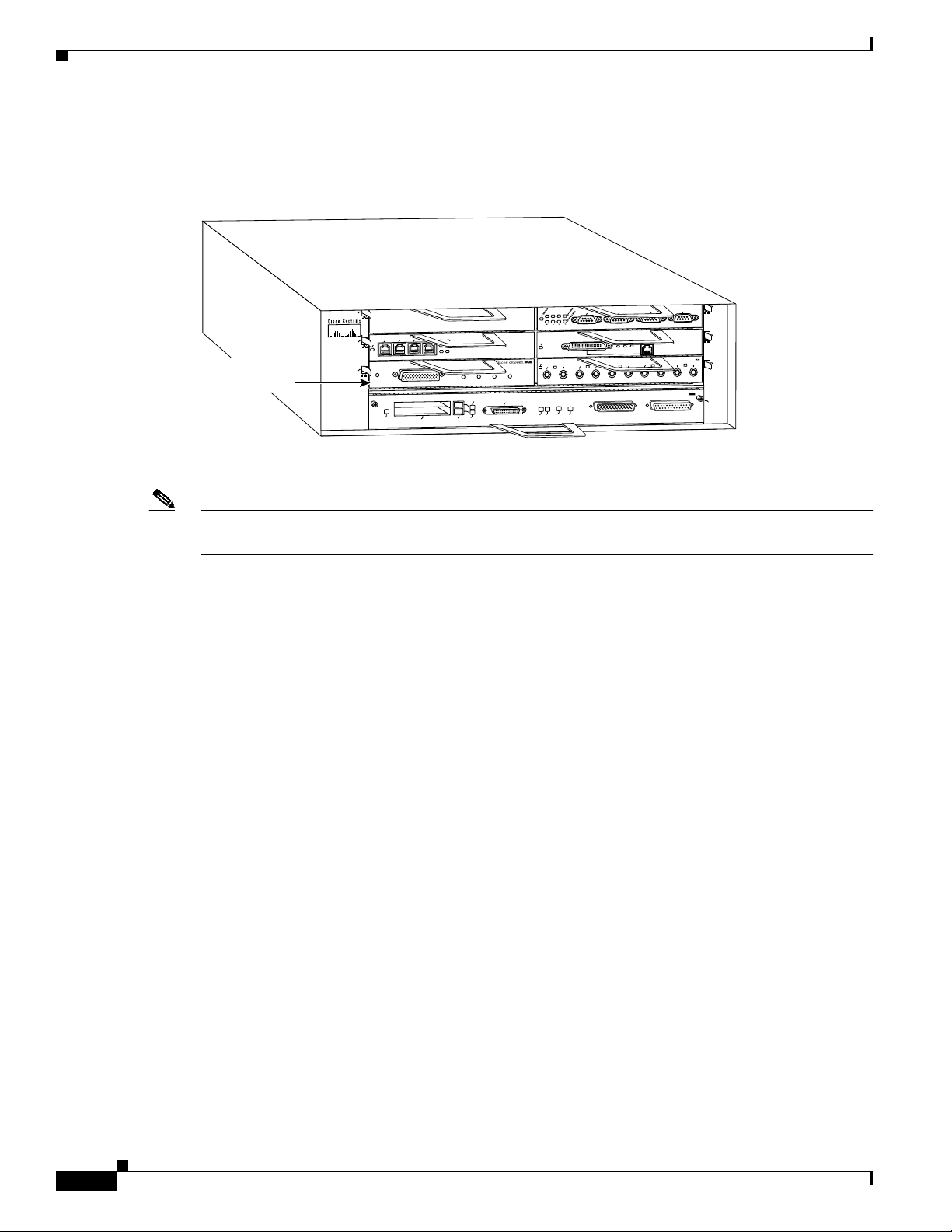
The HP ESCON PA(Figure 1) provides a single channel attachment interface for connecting Cisco 7200
series routers to an ESCON director or to a mainframe channel.
Overview
OL-3743-02
Note The Cisco 7200 series routers support the OIR of all port adapter types.
Figure 1 ESCON Channel Port Adapter, Faceplate View
HP ESCON PA
LOADED
PRESENT
EN
ONLINE
SIGNAL
The HP ESCON PA has a single female duplex connector and has 128 MB of DRAM. There are no
memory options for the HP ESCON PA.
PA-4C-E 1-Port High-Performance ESCON Channel Port Adapter Installation and Configuration
45335
5
Page 6
Overview
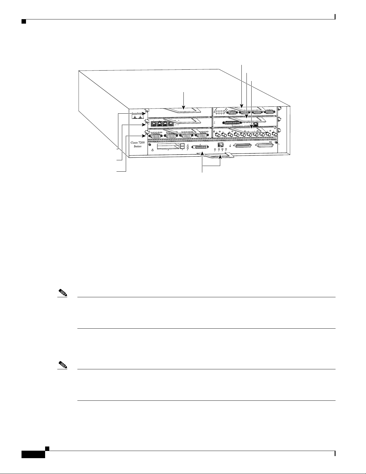
You can install the HP ESCON PAin any of the available port adapter slots in a Cisco 7200 series router.
Figure 2 shows an HP ESCON PA installed in port adapter slot 1 of a Cisco 7206.
Figure 2 Cisco 7206 with an HP ESCON PA in Port Adapter Slot 1
TOKEN RING
6
3
2
1
0
FAST ETHERNET
ETHERNET-10BFL
RX
4
TX
4
2
0
H11717
RJ45
LINK
RX
1
MII
0
RX
TX
2
FAST ETHERNET INPUT/OUTPUT CONTROLLER
TX
RX
TX
3
ENABLED
EN
TX
RX
0
OK
CPU RESET
1O POWER
Parallel channel
port adapter
Cisco 7200
Series
5
3
2
1
0
ENABLED
3
EN
1
ENABLED
LINK
3
1
2
0
PRESENT
EJECT
PCMCIA
ETHERNET 10BT
ONLINE
SIGNAL
LOADED
SLOT 1
FE MII
FE
FE LINK
SLOT 0
ENABLE
Note The HP ESCON PA supports online insertion and removal (OIR), which allows you to install or remove
an HP ESCON PA while the system is operating without shutting down system power.
The entire HP ESCON PA microcode image is delivered on a router Flash memory card or SanDisk
memory device, or you can download it from Cisco.com.
• When ordered as a spare, the HP ESCON PA microcode is available via Cisco.com.
• When ordered as part of a new system, the HP ESCON PA microcode is available on Flash memory
cards and SanDisk memory devices (which also include the Cisco IOS release compatible with the
microcode version) and via Cisco.com.
• When shipped with a new system, there is a default setting in Cisco IOS that points to the HP
ESCON PA microcode with which it has been virtually bundled (separately bundled and preloaded
onto the Flash memory card or SanDisk memory device along with the compatible Cisco IOS
software). The Cisco IOS software loads the HP ESCON PA microcode image onto the port adapter
when the router boots and when an HP ESCON PA is inserted into a router that has already been
booted.
We recommend that you use the version of the HP ESCON PA microcode that is virtually bundled with
your Cisco IOS software. If you choose not to, you must copy a microcode image onto the router Flash
memory card or SanDisk memory device and use the microcode router configuration command to
instruct the Cisco IOS software to use the microcode image you copied instead of the microcode image
virtually bundled with your version of the Cisco IOS software.
• For instructions on placing HP ESCON PA microcode on the router Flash memory card, see the
“Copying a New Image to the Flash Memory Card on a Cisco 7200 Series Router” section on
page 36.
• For instructions on placing HP ESCON PA microcode on the SanDisk memory device, see the
“Using SanDisk Devices” section on page 38.
• For instructions on configuring Cisco IOS to use an HP ESCON PA image from the router Flash
memory card or SanDisk memory device, refer to the “Configuring the HP ESCON PA Microcode”
section on page 34.
PA-4C-E 1-Port High-Performance ESCON Channel Port Adapter Installation and Configuration
6
OL-3743-02
Page 7

• For general information on HP ESCON PA microcode, refer to the “HP ESCON PA Microcode
Overview” section on page 12. For specific instructions to configure the Cisco IOS software to
download microcode from the router Flash memory card or SanDisk memory device, refer to the
“Upgrading the HP ESCON PA Microcode from Cisco.com” section on page 33.
ESCON Specifications
Table 1 lists the specifications for the ESCON interfaces.
Table 1 ESCON Specifications
Characteristic ESCON Specification
Supported processor I/O architectures ESA/390
Bit transmission Serial
Maximum distance (for LED with
ESCON)
Channel data rate Up to 17 MBps
Signaling rate 200 Mbps
Cable types Fiber-optic (62.5/125 micron multimode)
Addition of devices to running systems Dynamic
Number of addressable devices per
channel
Connectable control units per channel Up to 59 (through a 9032 ESCON Director)
Connectable channels per adapter Up to 59 (through a 9032 ESCON Director); varies by
1. The HP ESCON PA requires dynamic = NO with HCD.
2. Where 256 represents available unit addresses, 16 represents the number of logical partitions (LPARs), 16 represents the
number of control unit images, and 253 represents the number of ESCON director paths. It is unlikely a system would have
the resources to support the total number of available addresses.
Overview
1.9 miles (3.1 km) point-to-point
5.7 miles (9.2 km) with two ESCON Directors and each hop
not exceeding 3 km.
1
256 x 16 x 16 x 253
2
control unit
LEDs
OL-3743-02
The functions of the HP ESCON PA LEDs are as follows:
• Enabled—Indicates that the HP ESCON PA is enabled for operation by the system.
• Present—Indicates that the ESCON channel is detected by the HP ESCON PA.
• Loaded—Indicates that the ESCON channel firmware is completely loaded.
• Signal—Indicates that the sync signal has been detected from the ESCON neighbor node.
• Online—Indicates that an establish-logical-path request has been received from the channel and that
the establish-logical-path request matches one of the paths configured on the HP ESCON PA.
PA-4C-E 1-Port High-Performance ESCON Channel Port Adapter Installation and Configuration
7
Page 8

Overview
Figure 3 shows the LED indicators.
Figure 3 HP ESCON PA LED Indicators
LOADED
PRESENT
EN
ONLINE
SIGNAL
46956
Table 2 shows the HP ESCON PA LED indicator sequences during a cold boot. The ENABLED LED is
not part of the following sequences; it remains on during the boot sequence (Figure 4).
Table 2 Cold Boot LED Sequence
Sequence Present Loaded Signal Online
1 Off On Off Off
2 Off Off Off On
3 Off On Off On
4 On Off Off Off
5 OnOnOffOff
6OnOffOffOn
7 OnOnOffOn
8 Off Off On Off
1
9
1. Indicates that the HP ESCON PA is starting to execute the microcode
and waiting for commands
Off Off Off Off
Figure 4 LED Boot Sequence
1*
2
3
LOADED
PRESENT
EN
ONLINE
SIGNAL
LOADED
PRESENT
EN
ONLINE
SIGNAL
LOADED
PRESENT
EN
ONLINE
SIGNAL
* Because of the short duration of the LEDs, you will typically
see only these LED sequences.
PA-4C-E 1-Port High-Performance ESCON Channel Port Adapter Installation and Configuration
8
4
5
6
LOADED
PRESENT
EN
ONLINE
SIGNAL
LOADED
PRESENT
EN
ONLINE
SIGNAL
LOADED
PRESENT
EN
ONLINE
SIGNAL
7*
8*
9
LOADED
PRESENT
EN
ONLINE
SIGNAL
LOADED
PRESENT
EN
ONLINE
SIGNAL
LOADED
PRESENT
EN
ONLINE
SIGNAL
46957
OL-3743-02
Page 9
ESCON Cable
Overview
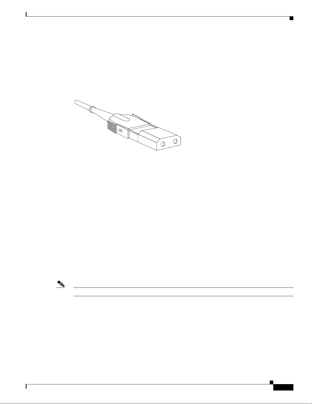
The ESCON channel interface uses 62.5/125 micrometer, multimode, fiber-opticcable with male duplex
connectors at each end (Figure 5). ESCON cables are not available from Cisco. Refer to the ESCON
specifications in and contact your cable supplier or the vendor of your host CPU to order the correct
ESCON cable.
Figure 5 ESCON Interface Duplex Connector for the ESCON Channel Port Adapter
H2454
Port Adapter Slot Locations on the Supported Platforms
The following sections provide port adapter slot locations and related information:
• Cisco 7200 Series Routers and Cisco 7200 VXR Routers Slot Numbering, page 9
Cisco 7200 Series Routers and Cisco 7200 VXR Routers Slot Numbering
Cisco 7204 routers and Cisco 7204VXR routers have four slots for port adapters, and one slot for an
input/output (I/O) controller. The slots are numbered from the lower left to the upper right, beginning
with slot 1 and continuing through slot 4. You can place a port adapter in any of the slots (slot 1 through
slot 4). Slot 0 is alwaysreserved for the I/O controller. The Cisco 7204 router and Cisco 7204VXR router
are not shown.
Cisco 7206 routers and Cisco 7206VXR routers have six slots for port adapters, and one slot for an
input/output (I/O) controller. The slots are numbered from the lower left to the upper right, beginning
with slot 1 and continuing through slot 6. You can place a port adapter in any of the six slots (slot 1
through slot 6). Slot 0 is always reserved for the I/O controller. Figure 6 shows the slot numbering on a
Cisco 7206 router. The Cisco 7206VXR router is not shown.
Note Interface ports are numbered from left to right starting with 0.
OL-3743-02
PA-4C-E 1-Port High-Performance ESCON Channel Port Adapter Installation and Configuration
9
Page 10
Overview
Figure 6 Port Adapter Slots in the Cisco 7206 Router
Blank port adapter
5
ETHERNET 10BT
ENABLED
FAST SERIAL
EN
CD
LB
RC
RD
TC
TD
CD
LB
RC
RD
TC
FE MII
SLOT 1
SLOT 0
TX
RX
0
RJ-45
MII
RJ45
RJ45
EN
OK
EN
1O PWR
LINK
Port adapter slot 5
Port adapter slot 3
3
2
1
0
3
ENABLED
EN
RC
RD
TC
TD
1
ENABLED
LINK
3
1
2
0
TD
CD
LB
RC
RD
TC
TD
CD
LB
EJECT
PCMCIA
Port adapter slot 6
Port adapter slot 4
Port adapter slot 2
1
0
RJ45
LINK
MII
0
TX
RX
TX
RX
2
1
FAST ETHERNET INPUT/OUTPUT CONTROLLER
CPU RESET
TOKEN RING
6
3
2
FAST ETHERNET
4
ETHERNET-10BFL
TX
RX
TX
RX
3
2
4
0
H6422
Port adapter slot 1
Identifying Interface Addresses
This section describes how to identify the interface addresses for the port adapter slots and ESCON
channel port numbers. Interface addresses specify the actual physical location of each interface port on
the router.
This address is composed of a two-part number in the format port-adapter-slot
number/interface-port-number, as follows:
• The first number identifies the port adapter slot in which the HP ESCON PA is installed.
• The second number identifies the interface port on the HP ESCON PA, which is always numbered
as interface 0 for the HP ESCON PA.
Note Some IBM channel attach software features are configured on a virtual port. On the CIP cards installed
in a Cisco 7500-series router, there are up to two physical ports, numbered 0 and 1, and a virtual port,
numbered 2. However, on the HP ESCON PA installed in a Cisco 7200 series router, the single physical
port and the virtual port are configured using the same port number identifier, number 0.
Interface ports maintain the same address regardless of whether other port adapters are installed or
removed from the slot. However, when you move a port adapter to a different slot, the first number in
the address changes to reflect the new port adapter slot number.
Port adapter slot 0
10
Note The HP ESCON PA is considered a high-speed port adapter; there are specific configuration guidelines
that must be observed. Refer to the publication Cisco 7200 Series PortAdapter HardwareConfiguration
Guidelines (Document Number 78-3471-xx), which shipped with your Cisco 7200 series chassis and is
also available on the Cisco Connection Documentation, Enterprise Series CD-ROM.
The following subsections describe the interface address formats for the supported platforms:
• Cisco 7200 Series Routers and Cisco 7200 VXR Routers Interface Addresses, page 11
PA-4C-E 1-Port High-Performance ESCON Channel Port Adapter Installation and Configuration
OL-3743-02
Page 11

Overview
Table 3 describes the interface addresses for the Cisco 7200 series routers, includingCisco 7200 VXR
routers.
Table 3 Identifying Interface Addresses
Platform Interface Address Format Numbers Syntax
Cisco 7200 series
routers and
Cisco 7200 VXR
routers (,7204,
Port-adapter-slot-number/interface-port-number Port adapter slot—11through 6 (depends
on the number of slots in the router)
Interface port—0
1/0
7204VXR, 7206,
7206VXR)
1. Port adapter slot 0 is reserved for the Fast Ethernet port on the I/O controller (if present).
Cisco 7200 Series Routers and Cisco 7200 VXR Routers Interface Addresses
In Cisco 7200 series routers, port adapter slot numbers port adapter slots are numbered from the lower
left to the upper right, beginning with port adapter slot 1 and continuing through port adapter slot 4 for
the Cisco 7204, and slot 6 for the Cisco 7206. Port adapter slot 0 is reserved for the optional Fast
Ethernet port on the I/O controller. For ESCON ports, the individual interface port numbers are always 0.
The interface address is composed of a two-part number in the format
port-adapter-slot-number/interface-port-number. For example, the ESCON port on an HP ESCON PA
in port adapter slot 3 would have the address 3/0. If the HP ESCON PA was in port adapter slot 1, the
interface address would be 1/0.
OL-3743-02
PA-4C-E 1-Port High-Performance ESCON Channel Port Adapter Installation and Configuration
11
Page 12

Preparing for Installation
Preparing for Installation
This section describes the general equipment, safety, and site preparation requirements for installing the
HP ESCON PA. It also includes microcode overview information.This section contains the following
subsections:
• Required Tools and Equipment, page 12
• HP ESCON PA Microcode Overview, page 12
• Hardware and Software Requirements, page 13
• Checking Hardware and Software Compatibility, page 14
• Safety Guidelines, page 15
• Laser LED Safety Information, page 18
Required Tools and Equipment
You need the following parts and tools to install an HP ESCON PA. If you need additional equipment,
contact a service representative for ordering information.
• HP ESCON PA
• ESCON interface cables
• ESD-prevention equipment or the disposable grounding wrist strap included with all upgrade kits,
field-replaceable units (FRUs), and spares
• An antistatic mat on which you can place the removed port adapter
• An antistatic container in which you can place the failed port adapter for shipment to the factory
HP ESCON PA Microcode Overview
Microcode, also known as firmware, is a set of processor-specific software instructions that enables and
manages the features and functions of a specific port adapter type. At system startup or reload, the
system loads the microcode for each port adapter type present in the system.
The entire HP ESCON PA microcode image is delivered on a router Flash memory card or SanDisk
memory device, or you can download it from Cisco.com.
New microcode is released to enable new features, improve performance, or fix known problems in
earlier versions. The Cisco 7200 series routers support downloadable software and microcode images
for most upgrades. This support lets you download new or upgraded images remotely, store the images
in router memory, and load the new images at system startup without physically accessing the router.
You can store multiple versions of an image in Flash or SanDisk memory for a specific processor type,
and use configuration commands to specify which version of the image loads at startup. All port adapters
of the same type (for example, all HP ESCON PA port adapters) use the same microcode image.
By default, the HP ESCON PA microcode is loaded from the router Flash memory card or SanDisk
memory device for the Cisco 7200 series routers. The default HP ESCON PA microcode version is found
by entering the show microcode command.
12
PA-4C-E 1-Port High-Performance ESCON Channel Port Adapter Installation and Configuration
OL-3743-02
Page 13

The following example is a partial display of the show microcode command output:
Router# show microcode
Microcode images for downloadable hardware
HW Type Microcode image names
-----------------------------------------ecpa default slot0:xcpa28-0
configured slot0:xcpa218-2
pcpa default slot0:xcpa28-0
Note In Cisco IOS Release 12.1(5)T or later, the filenames of all released HP ESCON PA microcode images
use the conventions xcpa28-nn (for example, xcpa28-1). Interim pre-release versions of HP ESCON PA
microcode images use the convention xcpa218-nnn (for example, xcpa218-2).
Hardware and Software Requirements
The show version command displays the current hardware configuration of the router, including the
system software version that is loaded and running. For the HP ESCON PA, the show microcode
command lists the recommended and the configured microcode version. The show controller command
shows the microcode version running on the HP ESCON PA in the router.
To view the current version of software or microcode stored on the router Flash memory card, use the
show flash slot0: or the dir slot0: EXEC commands. Refer to the “Upgrading Your HP ESCON PA
Microcode” section on page 33 for basic configuration information.
If the displays indicate that the required system software and microcode are not available in your system,
refer to the “Obtaining Documentation, Obtaining Support, and Security Guidelines” section on page 3
or contact a service representative for upgrade information.
The following subsections indicate the minimum hardware and software requirements for each
supported platform:
• Cisco 7200 Series Routers and Cisco 7200 VXR Routers Hardware and Software Requirements,
page 13
Preparing for Installation
Cisco 7200 Series Routers and Cisco 7200 VXR Routers Hardware and Software Requirements
The minimum hardware and software requirements for the HP ESCON PA on Cisco 7200 series and
Cisco 7200 VXR series routers are:
• The HP ESCON PA is used in the Cisco 7200 series routers and can be installed in any available
port adapter slot.
• The Cisco 7200 series router requires a minimum of 32 MB of dynamic RAM (DRAM). The HP
ESCON PA is a high-speed interface (100 bandwidth points).
Note For port adapter hardware and memory configuration guidelines for the Cisco 7200 series routers, refer
to the document Cisco 7200 Series Port Adapter Hardware Configuration Guidelines at the following
URL:
http://www.cisco.com/en/US/products/hw/modules/ps2033/products_configuration_guide_book09186a
00801056ef.htm
• The HP ESCON PA requires that the Cisco 7200 series router is running Cisco IOS
Release 12.1(5)T or later.
PA-4C-E 1-Port High-Performance ESCON Channel Port Adapter Installation and Configuration
OL-3743-02
13
Page 14

Preparing for Installation
Table 4 lists the specific Cisco IOS software images that are compatible with the HP ESCON PA.
Table 4 Cisco IOS Release Image Names
Cisco IOS Release Image Names
Release 12.1(5)T c7200-aejs-mz
c7200-aejs40-mz
c7200-aejs56i-mz
c7200-ajs-mz
c7200-ajs40-mz
c7200-ajs56i-mz
c7200-js-mz
c7200-js40-mz
c7200-js56i-mz
c7200-ds-mz
c7200-ds40-mz
c7200-ds56i-mz
Table 5 specifies the recommended minimum level of HP ESCON PA microcode for the corresponding
Cisco IOS release.
Table 5 Cisco IOS Releases and HP ESCON PA Microcode Image
Cisco IOS Release HP ESCON PA Image
Release 12.1(5)T xcpa28-0
For the latest Cisco IOS release that supports the HP ESCON PA on the Cisco 7200 series routers, refer
to “Checking Hardware and Software Compatibility” section on page 14.
Checking Hardware and Software Compatibility
To check the minimum software requirements of Cisco IOS software with the hardware installed on your
router, Cisco maintains the Software Advisor tool on Cisco.com. This tool does not verify whether
modules within a system are compatible, but it does provide the minimum IOS requirements for
individual hardware modules or components.
Note Access to this tool is limited to users with Cisco.com login accounts.
To access Software Advisor, click Log In at Cisco.com and go to Support > Tools and Resources. You
can also access the tool by pointing your browser directly to
http://www.cisco.com/en/US/support/tsd_most_requested_tools.html.
Choose a product family or enter a specific product number to search for the minimum supported
software release needed for your hardware.
14
PA-4C-E 1-Port High-Performance ESCON Channel Port Adapter Installation and Configuration
OL-3743-02
Page 15

Safety Guidelines
This section provides safety guidelines that you should follow when working with any equipment that
connects to electrical power or telephone wiring.
Safety Warnings
Safety warnings appear throughout this publication in procedures that, if performed incorrectly, might
harm you. A warning symbol precedes each warning statement.
Preparing for Installation
Warning
Waarschuwing
Varoitus
IMPORTANT SAFETY INSTRUCTIONS
This warning symbol means danger.Youare in a situation that could cause bodily injury. Before you
work on any equipment, be aware of the hazards involved with electrical circuitry and be familiar
with standard practices for preventing accidents. Use the statement number provided at the end of
each warning to locate its translation in the translated safety warnings that accompanied this
device. Statement 1071
SAVE THESE INSTRUCTIONS
BELANGRIJKE VEILIGHEIDSINSTRUCTIES
Dit waarschuwingssymbool betekent gevaar. U verkeert in een situatie die lichamelijk letsel kan
veroorzaken. Voordat u aan enige apparatuur gaat werken, dient u zich bewust te zijn van de bij
elektrische schakelingen betrokken risico's en dient u op de hoogte te zijn van de standaard
praktijken om ongelukken te voorkomen. Gebruik het nummer van de verklaring onderaan de
waarschuwing als u een vertaling van de waarschuwing die bij het apparaat wordt geleverd, wilt
raadplegen.
BEWAAR DEZE INSTRUCTIES
TÄRKEITÄ TURVALLISUUSOHJEITA
Tämä varoitusmerkki merkitsee vaaraa. Tilanne voi aiheuttaa ruumiillisia vammoja. Ennen kuin
käsittelet laitteistoa, huomioi sähköpiirien käsittelemiseen liittyvät riskit ja tutustu
onnettomuuksien yleisiin ehkäisytapoihin. Turvallisuusvaroitusten käännökset löytyvät laitteen
mukana toimitettujen käännettyjen turvallisuusvaroitusten joukosta varoitusten lopussa näkyvien
lausuntonumeroiden avulla.
OL-3743-02
Attention
SÄILYTÄ NÄMÄ OHJEET
IMPORTANTES INFORMATIONS DE SÉCURITÉ
Ce symbole d'avertissement indique un danger. Vous vous trouvez dans une situation pouvant
entraîner des blessures ou des dommages corporels. Avant de travailler sur un équipement, soyez
conscient des dangers liés aux circuits électriques et familiarisez-vous avec les procédures
couramment utilisées pour éviter les accidents. Pour prendre connaissance des traductions des
avertissements figurant dans les consignes de sécurité traduites qui accompagnent cet appareil,
référez-vous au numéro de l'instruction situé à la fin de chaque avertissement.
CONSERVEZ CES INFORMATIONS
PA-4C-E 1-Port High-Performance ESCON Channel Port Adapter Installation and Configuration
15
Page 16

Preparing for Installation
Warnung
Avvertenza
Advarsel
WICHTIGE SICHERHEITSHINWEISE
DiesesWarnsymbol bedeutet Gefahr.Siebefindensich in einerSituation, diezu Verletzungenführen
kann. Machen Sie sich vor der Arbeit mit Geräten mit den Gefahren elektrischer Schaltungen und
den üblichen Verfahren zur Vorbeugung vor Unfällen vertraut. Suchen Sie mit der am Ende jeder
Warnung angegebenen Anweisungsnummer nach der jeweiligen Übersetzung in den übersetzten
Sicherheitshinweisen, die zusammen mit diesem Gerät ausgeliefert wurden.
BEWAHREN SIE DIESE HINWEISE GUT AUF.
IMPORTANTI ISTRUZIONI SULLA SICUREZZA
Questo simbolo di avvertenza indica un pericolo. La situazione potrebbe causare infortuni alle
persone. Prima di intervenire su qualsiasi apparecchiatura, occorre essere al corrente dei pericoli
relativi ai circuiti elettrici e conoscere le procedure standard per la prevenzione di incidenti.
Utilizzare il numero di istruzione presente alla fine di ciascuna avvertenza per individuare le
traduzioni delle avvertenze riportate in questo documento.
CONSERVARE QUESTE ISTRUZIONI
VIKTIGE SIKKERHETSINSTRUKSJONER
Dette advarselssymbolet betyr fare. Du er i en situasjon som kan føre til skade på person. Før du
begynner å arbeide med noe av utstyret, må du være oppmerksom på farene forbundet med
elektriske kretser, og kjenne til standardprosedyrer for å forhindre ulykker.Bruk nummeret i slutten
avhver advarsel for å finneoversettelsen i de oversatte sikkerhetsadvarslene som fulgte med denne
enheten.
Aviso
¡Advertencia!
TA VARE PÅ DISSE INSTRUKSJONENE
INSTRUÇÕES IMPORTANTES DE SEGURANÇA
Este símbolo de aviso significa perigo. Você está em uma situação que poderá ser causadora de
lesões corporais. Antes de iniciar a utilização de qualquer equipamento, tenha conhecimento dos
perigos envolvidos no manuseio de circuitos elétricos efamiliarize-se com as práticas habituais de
prevenção de acidentes. Utilize o número da instrução fornecido ao final de cada aviso para
localizar sua tradução nos avisos de segurança traduzidos que acompanham este dispositivo.
GUARDE ESTAS INSTRUÇÕES
INSTRUCCIONES IMPORTANTES DE SEGURIDAD
Este símbolo de aviso indica peligro. Existe riesgo para su integridad física. Antes de manipular
cualquier equipo, considere los riesgos de la corriente eléctrica y familiarícese con los
procedimientos estándar de prevención de accidentes. Al final de cada advertencia encontrará el
número que le ayudará a encontrar el texto traducido en el apartado de traducciones que acompaña
a este dispositivo.
GUARDE ESTAS INSTRUCCIONES
16
PA-4C-E 1-Port High-Performance ESCON Channel Port Adapter Installation and Configuration
OL-3743-02
Page 17

Preparing for Installation
Varning!
VIKTIGA SÄKERHETSANVISNINGAR
Denna varningssignal signalerar fara. Du befinner dig i en situation som kan leda till personskada.
Innan du utför arbete på någon utrustning måste du vara medveten om farorna med elkretsar och
känna till vanliga förfaranden för att förebygga olyckor. Använd det nummer som finns i slutet av
varje varning för att hitta dess översättning i de översatta säkerhetsvarningar som medföljer denna
anordning.
SPARA DESSA ANVISNINGAR
OL-3743-02
PA-4C-E 1-Port High-Performance ESCON Channel Port Adapter Installation and Configuration
17
Page 18

Preparing for Installation
Electrical Equipment Guidelines
Follow these basic guidelines when working with any electrical equipment:
• Before beginning any procedures requiring access to the chassis interior, locate the emergency
power-off switch for the room in which you are working.
• Disconnect all power and external cables before moving a chassis.
• Do not work alone when potentially hazardous conditions exist and never assume that power has
been disconnected from a circuit; always check.
• Do not perform any action that creates a potential hazard to people or makes the equipment unsafe.
Carefully examine your work area for possible hazards such as moist floors, ungrounded power
extension cables, and missing safety grounds.
Preventing Electrostatic Discharge Damage
Electrostatic discharge (ESD) damage, which can occur when electronic cards or components are
improperly handled, results in complete or intermittent failures. Port adapters and processor modules
comprise printed circuit boards that are fixed in metal carriers. Electromagnetic interference (EMI)
shielding and connectors are integral components of the carrier. Although the metal carrier helps to
protect the board from ESD, use a preventive antistatic strap during handling.
The following guidelines help prevent ESD damage:
• Always use an ESD wrist or ankle strap and ensure that it makes good skin contact.
• Connect the equipment end of the strap to an unfinished chassis surface.
• When installing a component use any available ejector levers or captive installation screws to
properly seat the bus connectors in the backplane or midplane. These devices prevent accidental
removal, provide proper grounding for the system, and help to ensure that bus connectors are
properly seated.
• When removing a component use any available ejector levers or captive installation screws to
release the bus connectors from the backplane or midplane.
• Handle carriers by available handles or edges only; avoid touching the printed circuit boards or
connectors.
• Place a removed component board-side-up on an antistatic surface or in a static shielding container.
If you plan to return the component to the factory, immediately place it in a static shielding
container.
• Avoid contact between the printed circuit boards and clothing. The wrist strap only protects
components from ESD voltages on the body; ESD voltages on clothing can still cause damage.
• Never attempt to remove the printed circuit board from the metal carrier.
Caution For safety, periodically check the resistance value of the antistatic strap. The measurement should be
between 1 and 10 megohm.
Laser LED Safety Information
The HP ESCON PA contains laser LEDs. The expansion module is classified as a Class 1 laser product
and is certified to conform to the requirements of EN60825-1:1994 and IEC825-1:1993.
PA-4C-E 1-Port High-Performance ESCON Channel Port Adapter Installation and Configuration
18
OL-3743-02
Page 19

Laser Radiation
Preparing for Installation
Class 1 laser products are not considered hazardous. The HP ESCON PA has embedded Class 3a laser
LED assemblies operating at a nominal wavelength of 850 nanometer and a maximum potential output
power of 1.25 milliwatts. The design of the HP ESCON PAincorporates engineering features including
current limiting, which ensures that there is no human access to LED radiation greater than Class 1 under
any set of operating, maintenance, or service conditions, including a single fault.
There are fewer than 0.442 milliwatts propagating in the link or in any portion of the module. Therefore,
according to IEC825-2:1993, Hazard Level 1 prevails in all parts of the system.
The LEDs are located on the front face of the module.
Warning
Waarschuwing
Varoitus
Attention
Warnung
Avvertenza
Advarsel
Aviso
¡Advertencia!
Varning!
Laser radiation is present when the system is open. Statement 1009
Laserstraling is aanwezig wanneer het systeem open is.
Lasersäteitä järjestelmän ollessa avoinna.
Production d'un rayonnement laser en position ouverte.
Laserstrahlung in geöffnetem Zustand.
Emissione di radiazioni laser quando il sistema è aperto.
Laserstråling er til stede når enheten er åpen.
Radiação laser presente quando aberto.
Radiación láser presente cuando el sistema está abierto.
Laserstrålning pågår när enheten är öppen.
OL-3743-02
PA-4C-E 1-Port High-Performance ESCON Channel Port Adapter Installation and Configuration
19
Page 20

Preparing for Installation
Staring into Laser Beam
Warning
Waarschuwing
Varoitus
Attention
Warnung
Avvertenza
Advarsel
Aviso
¡Advertencia!
Varning!
Do not stare into the laser beam. Statement 1010
Niet in de straal staren.
Älä katso säteeseen.
Ne pas fixer le faisceau des yeux.
Nicht direkt in den Strahl blicken.
Non fissare il raggio con gli occhi.
Stirr ikke på strålen.
Não olhe fixamente para o raio.
No mirar fijamente el haz.
Laserstrålning när enheten är öppen.
20
PA-4C-E 1-Port High-Performance ESCON Channel Port Adapter Installation and Configuration
OL-3743-02
Page 21

Removing and Installing Port Adapters
This section describes how to remove port adapters from supported platforms and also howto install new
or replacement port adapters.This section contains the following subsections:
• Handling Port Adapters, page 21
• Online Insertion and Removal, page 22
• Port Adapter Removal and Installation, page 23
• Attaching the HP ESCON PA to the Channel, page 25
Handling Port Adapters
Each port adapter circuit board is mounted to a metal carrier and is sensitive to electrostatic discharge
(ESD) damage.
Note When a slot is not in use, a blank port adapter must fill the empty slot to allow the router or switch to
conform to electromagnetic interference (EMI) emissions requirements and to allow proper airflow
across the installed port adapters. If you plan to install a new port adapter in a slot that is not in use, you
must first remove the blank port adapter.
Removing and Installing Port Adapters
Caution Always handle the port adapter by the carrier edges and handle; never touch the port adapter components
or connector pins. Always use an ESD wrist strap when handling equipment. (See Figure 7.)
Figure 7 Handling a Port Adapter
Metal carrier
Printed circuit board
H6420
OL-3743-02
PA-4C-E 1-Port High-Performance ESCON Channel Port Adapter Installation and Configuration
21
Page 22

Removing and Installing Port Adapters
Online Insertion and Removal
The Cisco 7200 series routers, including Cisco 7200 VXR routers, support online insertion and removal
(OIR) of all port adapters. You do not need to power down the router when removing and replacing an
HP ESCON PA.
Note As you disengage the module from the router or switch, OIR administratively shuts down all active
interfaces in the port adapter.
OIR allows you to install and replace port adapters while the router is operating; you do not need to
notify the software or shut down the system power, although you should not run traffic through the port
adapter you are removing while it is being removed. OIR is a method that is seamless to end users on
the network, maintains all routing information, and preserves sessions.
It is wise to gracefully shut down the system before removing a port adapter that has activetraffic moving
through it. Removing a module while traffic is flowing through the ports can cause system disruption.
Once the port adapter is inserted, the ports can be brought back up.
The following is a functional description of OIR for background information only; for specific
procedures for installing and replacing a port adapter in a supported platform, refer to the “Port Adapter
Removal and Installation” section on page 23.
Each port adapter has a bus connector that connects it to the router.The connector has a set of tiered pins
in three lengths that send specific signals to the system as they make contact with the port adapter. The
system assesses the signals it receives and the order in which it receives them to determine if a port
adapter is being removed from or introduced to the system. From these signals, the system determines
whether to reinitialize a new interface or to shut down a disconnected interface.
Specifically, when you insert a port adapter,the longest pins make contact with the port adapter first, and
the shortest pins make contact last. The system recognizes the signals and the sequence in which it
receives them.
When you remove or insert a port adapter, the pins send signals to notify the system of changes. The
router then performs the following procedure:
1. Rapidly scans the system for configuration changes.
2. Initializes newly inserted port adapters or administratively shuts down any vacant interfaces.
3. Brings all previously configured interfaces on the port adapter back to their previously installed
state. Any newly inserted interface is put in the administratively shutdown state, as if it was present
(but not configured) at boot time. If a similar port adapter type is reinserted into a slot, its ports are
configured and brought online up to the port count of the originally installed port adapter of that
type.
22
Note Before you begin installation, read the “Required Tools and Equipment” section on page 12 for a list of
parts and tools required for installation.
PA-4C-E 1-Port High-Performance ESCON Channel Port Adapter Installation and Configuration
OL-3743-02
Page 23

Port Adapter Removal and Installation
In this section, the illustrations that follow give step-by-step instructions on how to remove and install
port adapters. Although the procedures may refer to a particular type of port adapter, the steps are the
same for installing and removing all types of port adapters. This section contains the following
illustrations:
• Cisco 7200 Series Routers and Cisco 7200 VXR Routers—Removing and Installing a Port Adapter,
page 24
Caution When performing the following procedures, wear a grounding wrist strap to avoid ESD damage to the
card. Some platforms have an ESD connector for attaching the wrist strap.
Removing and Installing Port Adapters
Warning
Caution When powering off the router, wait a minimum of 30 seconds before powering it on again.
Hazardous voltage or energy is present on the backplane when the system is operating. Use caution
when servicing. Statement 1034
OL-3743-02
PA-4C-E 1-Port High-Performance ESCON Channel Port Adapter Installation and Configuration
23
Page 24

Removing and Installing Port Adapters
Cisco 7200 Series Routers and Cisco 7200 VXR Routers—Removing and Installing a Port Adapter
Step 1
To remove the port adapter, place
the port adapter lever in the
unlocked position. (See A.) The
port adapter lever remains in the
unlocked position.
Step 2
Grasp the handle of the port adapter
and pull the port adapter from the
router, about halfway out of its slot.
If you are removing a blank port
adapter, pull the blank port adapter
completely out of the chassis slot.
Step 3
With the port adapter halfway out of
the slot, disconnect all cables from
the port adapter. After disconnecting
the cables, pull the port adapter
from its chassis slot.
Step 4
To insert the port adapter, carefully
align the port adapter carrier
between the upper and the lower
edges of the port adapter slot.
(See B.)
Step 5
Carefully slide the new port adapter
halfway into the port adapter slot.
(See B.)
Step 6
With the port adapter halfway into
the slot, connect all required cables
to the port adapter. After connecting
all required cables, carefully slide
the port adapter all the way into the
slot until the port adapter is seated
in the router midplane.
A
Note: This adapter
removal applies to any
port or service adapter.
Slot
guide
B
Cisco 7200
Series
Cisco 7200
Series
Port adapter lever
(locked position)
5
3
2
1
0
LINK
3
ENABLED
EN
TD
1
1
0
CD
LB
RC
RD
TC
TD
CD
LB
RC
RD
TC
ENABLED
PCMCIA
ETHERNET 10BT
3
2
FAST SERIAL
LB
RC
RD
TC
TD
CD
LB
RC
RD
TC
TD
SLOT 1
FE MII
EJECT
SLOT 0
0
ENABLED
CD
CPU RESET
RJ-45
MII
RJ45
RJ45
EN
OK
EN
1O PWR
LINK
RJ45
LINK
MII
0
FAST ETHERNET INPUT/OUTPUT CONTROLLER
FAST ETHERNET
4
2
0
TOKEN RING
6
3
2
1
Port adapter lever
(unlocked position)
TOKEN RING
6
3
2
1
5
3
2
1
0
LINK
3
3
ENABLED
1
1
2
0
ENABLED
PCMCIA
ETHERNET 10BT
FE MII
SLOT 1
EJECT
SLOT 0
0
ENABLED
CPU RESET
RJ-45
MII
RJ45
RJ45
EN
OK
EN
1O PWR
LINK
RJ45
LINK
MII
0
FAST ETHERNET INPUT/OUTPUT CONTROLLER
FAST ETHERNET
4
2
27996
Step 7
After the port adapter is properly
seated, lock the port adapter lever.
(See A.)
PA-4C-E 1-Port High-Performance ESCON Channel Port Adapter Installation and Configuration
24
OL-3743-02
Page 25

Attaching the HP ESCON PA to the Channel
Caution We recommend that an authorized service representative or other qualified service person perform the
following procedure. To prevent hardware problems with your host processor, all the channel
connections must be tight. A loose connection can cause the host processor or its channel to halt. Every
cable must be tightly seated in its connector.
To attach the ESCON cable between the HP ESCON PA and the host channel:
Step 1 Use the shutdown interface command on the router to shut down the HP ESCON PA interface. This
action prevents excessive error messages from being sent to the router log output. In addition, we
recommend that you vary offline the host channel to which the HP ESCON PA will be attached.
Note For instructions on how to vary offline the host channel, refer to the documentation for your
mainframe operating system.
Step 2 Attach an ESCON cable between the HP ESCON PA and the host channel (Figure 8). Make certain the
ESCON cable plug “clicks” in place in the receptacle on the HP ESCON PA. Connection problems may
result if the plug does not click in place.
Step 3 Visually inspect the connection to make sure it is not loose.
Removing and Installing Port Adapters
Figure 8 Connecting an ESCON Cable to an HP ESCON PA
LOADED
PRESENT
EN
ONLINE
SIGNAL
HP ESCON PA
46955
To an ESCON Director
(switch) or host CPU
Step 4 Vary online the host channel. For instructions on how to vary the host channel online, refer to the
documentation for your mainframe operating system.
Step 5 Use the no shutdown interface configuration command to enable the HP ESCON PA interface.
OL-3743-02
PA-4C-E 1-Port High-Performance ESCON Channel Port Adapter Installation and Configuration
25
Page 26

Configuring the HP ESCON PA
Configuring the HP ESCON PA
To continue your port adapter installation, you must configure the HP ESCON PA interface. The
instructions that follow apply to all supported platforms. Minor differences among the platforms—with
Cisco IOS software commands—are noted.
This section contains the following subsections:
• Using the EXEC Command Interpreter, page 26
• Configuring the HP ESCON PA Interface, page 27
• Checking the Configuration, page 28
• Upgrading Your HP ESCON PA Microcode, page 33
• Using Flash Memory, page 36
• Using SanDisk Devices, page 38
• Running HP ESCON PA Diagnostic Tests, page 39
Using the EXEC Command Interpreter
You modify the configuration of your router through the software command interpreter called the EXEC
(also called enable mode). You must enter the privileged level of the EXEC command interpreter with
the enable command before you can use the configure command to configure a new interface or to
change the existing configurationof an interface. The system prompts you for a password if one has been
set.The system prompt for the privileged level ends with a pound sign (#) instead of an angle bracket (>).
At the console terminal, use the following procedure to enter the privileged level:
Step 1 At the user-level EXEC prompt, enter the enable command. The EXEC prompts you for a
privileged-level password as follows:
Router> enable
Password:
Step 2 Enter the password (the password is case sensitive).For security purposes, the password is not displayed.
When you enter the correct password, the system displays the privileged-level system prompt (#):
Router#
26
PA-4C-E 1-Port High-Performance ESCON Channel Port Adapter Installation and Configuration
OL-3743-02
Page 27

Configuring the HP ESCON PA Interface
After you verify that the new HP ESCON PA is installed correctly, use the configure command to
configurethe new interfaces. The enabled LED (EN) goes on when the port adapter is installed correctly
(Figure 3). Before you begin to configure the interface, be prepared with the following information:
• Protocols and encapsulations you plan to use on the new interfaces.
• Protocol-specific information, such as internet protocol (IP) addresses if you will configure the
interfaces for IP routing.
• Special services you plan to use on the interface, such as Common Link Access for Workstations
(CLAW), offload support, TN3270 server support, CIP SNA, or Cisco MultiPath Channel. For more
information on these special services, see the Cisco IOS Bridging and IBM Networking
Configuration Guide.
If you installed a new HP ESCON PA interface or if you want to change the configuration of an existing
interface, you must enter configuration mode to configure the new interfaces. If you replaced an HP
ESCON PA that was previously configured, the system will recognize the new HP ESCON PA interface
and bring it up in its existing configuration. An HP ESCON PA removed from one slot and replaced in
another slot must be reconfigured.
Configuring the HP ESCON PA
Note Configuration commands are executed from the privileged level of the EXEC command interpreter,
which usually requires password access. Refer to the “Using the EXEC Command Interpreter” section
on page 26 and contact your system administrator, if necessary, to obtain access.
The following sections provide specific information about configuring the HP ESCON PA interface:
• Performing a Basic Interface Configuration, page 27
Performing a Basic Interface Configuration
This section describes the procedure for performing a basic configuration of an HP ESCON PAinterface.
Press the Return key after each step unless otherwise noted. At any time you can exit the privileged level
and return to the user level by entering disable at the prompt as follows:
Router# disable
Router>
The following example describes a basic configuration procedure:
Step 1 Enter configuration mode and specify that the console terminal will be the source of the router
configuration commands, as follows:
Router# configure terminal
Enter configuration commands, one per line. End with CNTL/Z.
Router(config)#
OL-3743-02
PA-4C-E 1-Port High-Performance ESCON Channel Port Adapter Installation and Configuration
27
Page 28

Configuring the HP ESCON PA
Step 2 At the prompt, enter the interface configuration mode by using the interface configuration command.
The following example prepares you to configure the interface on the channel port adapter in slot 2,
port 0:
Router(config)# interface channel 2/0
Step 3 If IP routing is enabled on the system, you can assign an IP address and subnet mask to the interface with
the ip address interface configuration, as in the following example:
Router(config-if)# ip address 1.1.1.10 255.255.255.0
Step 4 Add any additional configuration subcommands required to enable routing protocols and set the
interface characteristics.
Step 5 Change the shutdown state to up and enable the interface as follows:
Router(config-if)# no shutdown
Step 6 Configure additional interfaces as required.
Step 7 When you have included all configurationcommands to complete the configuration, press Ctrl-Z to exit
configuration mode. You may also type end to exit configurationmode and return to the EXEC prompt.
Step 8 Write the new configuration to nonvolatile memory as follows:
Router# copy running-config startup-config
[OK]
Router#
For complete descriptions of interface subcommands and the configuration options available for each
platform, refer to the publications listed in the “Related Documentation” section on page 3.
To check the interface configuration using show commands, see the “Checking the Configuration”
section on page 28.
Checking the Configuration
After configuring the new interface, use the show commands to display the status of the new interface
or all interfaces and use the ping command to check connectivity. This section includes the following
subsections:
• Using show Commands to Verify the New Interface Status, page 28
• Using the Ping Command to Verify Network Connectivity, page 32
Using show Commands to Verify the New Interface Status
Use show commands to verify that the new interfaces are configured and operating correctly, as follows:
Step 1 Display the system hardware configuration with the show version command. Ensure that the list
includes the new interfaces.
Step 2 Display all the current port adapters and their interfaces with the show controllers command. Verify that
the new HP ESCON PA appears in the correct slot.
28
PA-4C-E 1-Port High-Performance ESCON Channel Port Adapter Installation and Configuration
OL-3743-02
Page 29

Configuring the HP ESCON PA
Step 3 Specify one of the new interfaces with the show interfaces port adapter type slot/interface command
and verify that the firstline of the display specifiesthe interface with the correct slot number. Also verify
that the interface and line protocol are in the correct state: up or down.
Step 4 Display the protocols configured for the entire system and specific interfaces with the show protocols
command. If necessary,return to configuration mode to add or remove protocol routing on the system or
specific interfaces.
Step 5 Display the running configuration file with the show running-config command. Display the
configuration stored in nonvolatile RAM (NVRAM) using the show startup-config command. Verify
that the configuration is accurate for the system and each interface.
If the interface is down and you configured it as up, or if the displays indicate that the hardware is not
functioning properly,ensure that the network interface is properly connected and terminated. If you still
have problems bringing up the interface, contact a service representative for assistance.
This section includes the following subsections:
• Using the show version or show hardware Commands, page 29
• Using the show controllers Commands, page 30
• Using the show diag Command, page 31
• Using the show interfaces Commands, page 31
Using the show version or show hardware Commands
Display the configuration of the router hardware, the software version, the names and sources of
configuration files, and the boot images using the show version (or show hardware) command.
Note The outputs that appear in this document may not match the output you receive when running these
commands. The outputs in this document are examples only.
Cisco 7200 Series and Cisco 7200 VXR Series Routers—Example Output of the show version Command
Following is an example of the show version command from a Cisco 7200 series router:
Router# show version
Cisco Internetwork Operating System Software
IOS (tm) 7200 Software (C7200-IS56I-M), Released Version 12.1
Copyright (c) 1986-2000 by cisco Systems, Inc.
Compiled Thu 27-Jul-00 13:22 by biff
Image text-base: 0x60008960, data-base: 0x613C4000
ROM: System Bootstrap, Version 12.1 RELEASE SOFTWARE (f)
BOOTFLASH: 7200 Software (C7200-BOOT-M), Version 12.1, RELEASE SOFTWARE R
router uptime is 5 hours, 6 minutes
System returned to ROM by reload at 04:35:10 UTC Thu Aug 10 2000
System image file is "tftp://181.23.250.2/jdoe/c7200-is56i-mz.121-5.T"
cisco 7206VXR (NPE300) processor (revision B) with 122880K/40960K bytes of memo.
Processor board ID 15463825
R7000 CPU at 262Mhz, Implementation 39, Rev 1.0, 256KB L2, 2048KB L3 Cache
6 slot VXR midplane, Version 2.0
OL-3743-02
Last reset from power-on
Bridging software.
PA-4C-E 1-Port High-Performance ESCON Channel Port Adapter Installation and Configuration
29
Page 30

Configuring the HP ESCON PA
X.25 software, Version 3.0.0.
4 Ethernet/IEEE 802.3 interface(s)
3 FastEthernet/IEEE 802.3 interface(s)
2 IBM channel interface(s)
125K bytes of non-volatile configuration memory.
20480K bytes of Flash PCMCIA card at slot 0 (Sector size 128K).
4096K bytes of Flash internal SIMM (Sector size 256K).
Configuration register is 0x100
Using the show controllers Commands
Display all the current interface processors and their interfaces using the show controllers command.
Note The outputs that appear in this document may not match the output you receive when running these
commands. The outputs in this document are examples only.
Cisco 7200 Series and Cisco 7200 VXR Series Routers—Example Output of the show controllers Command
Following is an example of the show controllers command that displays information about a specific
HP ESCON PA:
Router# show controllers channel 2/0
ECPA 2, hardware version 1.0, microcode version 218.6
Mailbox commands:0 forevers, 0 max elapsed usecs
Microcode loaded from flash slot0:xcpa218-6_kernel_ecpa4
Loaded:seg_802 Rev. 0 Compiled by jdoe on Thu 07-Sep-2000 12:
Loaded:seg_csna Rev. 0 Compiled by jdoe on Thu 07-Sep-2000 12:
Loaded:seg_eca Rev. 0 Compiled by jdoe on Thu 07-Sep-2000 12:
Loaded:seg_sslc Rev. 0 Compiled by jdoe on Thu 07-Sep-2000 12:
Loaded:seg_tcpip Rev. 0 Compiled by jdoe on Thu 07-Sep-2000 12:
Loaded:seg_tn3270 Rev. 0 Compiled by jdoe on Thu 07-Sep-2000 12:
EPROM version 0.0, VPLD version 0.0
ECA0:hw version 02, microcode version C50602D4
Load metrics:
Memory dram 118412048/128M
CPU 1m 1%, 5m 2%, 60m 2%
DMA 1m 1%, 5m 0%, 60m 0%
ECA0 1m 0%, 5m 0%, 60m 0%
Interface Channel2/0
Hardware is Escon Channel
HW Registers CPU init=0x021441A0 LED control=0x00045DDF Reset Satus=0x00000002
HW Poll Register 4B0D5240:[00000001]
30
Free buffer queues
queue=0 max_entries=128 size=600 head=71 ring=4B0EB060
queue=1 max_entries=32 size=4520 head=23 ring=4B07D380
queue=2 max_entries=64 size=4520 head=63 ring=4B07D440
Tx Queues
queue=0 head=0 tail=0 tx_cnt=0 tx_pakcnt=0
max_entries=128 type=1 poll_index=0 ring=4B07D580
fspak buffers swapped out=0
queue=1 head=12 tail=12 tx_cnt=0 tx_pakcnt=0
max_entries=32 type=2 poll_index=1 ring=4B0EB2A0
fspak buffers swapped out=0
Rx Queues
max_entries=221 poll_index=3 head=96 ring=4B0EB3E0
PA-4C-E 1-Port High-Performance ESCON Channel Port Adapter Installation and Configuration
OL-3743-02
Page 31

Using the show diag Command
Display the type of port adapter installed in your system using the show diag command.
Note The outputs that appear in this document may not match the output you receive when running these
commands. The outputs in this document are examples only.
Cisco 7200 Series and Cisco 7200 VXR Series Routers—Example Output of the show diag Command
Followingis an example of the show diag command from a Cisco 7200 series router with an HP ESCON
PA installed in port adapter slot 4:
Router# show diag 2
Slot 2:
Escon Port adapter, 1 port
Port adapter is analyzed
Port adapter insertion time 00:05:00 ago
EEPROM contents at hardware discovery:
Hardware Revision :1.0
Top Assy. Part Number :800-06347-02
Part Number :73-4454-02
Board Revision :02
PCB Serial Number :18902852000
RMA History :00
Fab Version :02
Fab Part Number :28-3405-02
Product Number :PA-4C-EB
EEPROM format version 4
EEPROM contents (hex):
0x00:04 FF 40 02 10 41 01 00 C0 46 03 20 00 18 CB 02
0x10:82 49 11 66 02 42 30 32 C1 8B 31 38 39 30 32 38
0x20:35 32 30 30 30 04 00 02 02 85 1C 0D 4D 02 CB 94
0x30:50 41 2D 34 43 2D 45 42 00 00 00 00 FF FF FF FF
0x40:FF FF FF FF FF FF FF FF FF FF FF FF FF FF FF FF
0x50:FF FF FF FF FF FF FF FF FF FF FF FF FF FF FF FF
0x60:FF FF FF FF FF FF FF FF FF FF FF FF FF FF FF FF
0x70:FF FF FF FF FF FF FF FF FF FF FF FF FF FF FF FF
Configuring the HP ESCON PA
Using the show interfaces Commands
Display information about a specific interface using the show interfaces command.
Note The outputs that appear in this document may not match the output you receive when running these
commands. The outputs in this document are examples only.
Cisco 7200 Series and Cisco 7200 VXR Series Routers—Example Output of the show interfaces Command
Followingis an example of the show interfaces channel command for an HP ESCON PAin port adapter
slot 4:
Router# show interface channel 4/0
Channel4/0 is up, line protocol is up
Hardware is Escon Channel
Internet address is 10.10.99.1/24
MTU 4472 bytes, BW 98304 Kbit, DLY 100 usec,
reliability 255/255, txload 1/255, rxload 1/255
Encapsulation CHANNEL, loopback not set
ECA adapter card
OL-3743-02
PA-4C-E 1-Port High-Performance ESCON Channel Port Adapter Installation and Configuration
31
Page 32

Configuring the HP ESCON PA
Data transfer rate 12 Mbytes, number of subchannels 0
Last input 00:14:09, output 00:00:58, output hang never
Last clearing of "show interface" counters never
Queueing strategy: fifo
Output queue 0/40, 69129 drops; input queue 0/75, 0 drops
5 minute input rate 220000 bits/sec, 239 packets/sec
5 minute output rate 289000 bits/sec, 252 packets/sec
788256 packets input, 84718668 bytes, 0 no buffer
Received 0 broadcasts, 0 runts, 0 giants, 0 throttles
0 input errors, 0 CRC, 0 frame, 0 overrun, 0 ignored, 0 abort
1378169 packets output, 680323725 bytes, 0 underruns
0 output errors, 0 collisions, 7 interface resets
0 output buffer failures, 0 output buffers swapped out
With the show interfaces command, use arguments such as the interface type and the port adapter slot
and port number to display information about a specific HP ESCON PA.
For complete command descriptions and examples for the Cisco 7200 series routers, refer to the
publications listed in the “Related Documentation” section on page 3.
Using the Ping Command to Verify Network Connectivity
Use the ping command to verify that an interface port is functioning properly and to check the path
between a specificport and connected devices at various locations on the network. This section provides
brief descriptions of the ping command. After you verify that the system has booted successfully and is
operational, you can use the ping command to verify the status of interface ports.
The ping command sends an echo request out to a remote device at the IP address that you specify.After
sending a series of signals, the command waits a specified time for the remote device to echo the signals.
Each returned signal is displayed as an exclamation point (!) on the console terminal; each signal that is
not returned before the specified time-out is displayed as a period (.). A series of exclamation points
(!!!!!) indicates a good connection; a series of periods (.....) or the messages “timed out” or “failed”
indicate that the connection failed.
The following example shows a successful ping command to a remote server with the IP
address 1.1.1.10:
Router# ping 1.1.1.10
Type escape sequence to abort.
Sending 5, 100-byte ICMP Echoes to 1.1.1.10, timeout is 2 seconds:
!!!!!
Success rate is 100 percent (5/5), round-trip min/avg/max = 1/15/64 ms
Router#
32
If the connection fails, verify that you have the correct IP address for the server and that the server is
active, then repeat the ping command.
For complete descriptions of interface configuration commands and the configuration options available
for each platform, refer to the publications listed in the “Related Documentation” section on page 3.
PA-4C-E 1-Port High-Performance ESCON Channel Port Adapter Installation and Configuration
OL-3743-02
Page 33

Upgrading Your HP ESCON PA Microcode
The following sections discuss HP ESCON PA microcode configuration requirements:
• How Does HP ESCON PA Microcode Ship?, page 33
• Upgrading the HP ESCON PA Microcode from Cisco.com, page 33
• Configuring the HP ESCON PA Microcode, page 34
For additional information about specificmicrocode requirements, refer to the “Hardware and Software
Requirements” section on page 13.
How Does HP ESCON PA Microcode Ship?
For the Cisco 7200 series routers, when the HP ESCON PA is ordered as part of a new system, the
HP ESCON PA microcode is available on a Flash memory card or SanDisk memory device (which also
includes the Cisco IOS release compatible with the microcode version) and via Cisco.com. When the HP
ESCON PA is ordered as a spare, the HP ESCON PA microcode is available via Cisco.com.
Note The HP ESCON PA-compatible microcode images are virtually bundled with all Cisco IOS releases that
support HP ESCON PAs. The virtual bundling of the microcode means that the microcode software is
loaded separately by the Cisco IOS software.
Configuring the HP ESCON PA
Upgrading the HP ESCON PA Microcode from Cisco.com
To upgrade the HP ESCON PA microcode obtained from Cisco.com, complete the following steps:
Note Perform the following procedure only if you are upgrading your microcode.
Caution To prevent system problems in the following procedure, you must be running Cisco IOS
Release 12.1(5)T or later. For information on upgrading your Cisco IOS software, refer to the
appropriate software configuration publication listed in the “Hardware and Software Requirements”
section on page 13.
Caution The microcode ECPA commands in this section will affect both the HP ESCON PA and earlier versions
of the ECPA if both types of port adapters are installed in the router.
To upgrade HP ESCON PA microcode images obtained from Cisco.com:
Step 1 Download the HP ESCON PA microcode image from Cisco.com to a TFTP server.
Step 2 Remove any configuration commands that specify a HP ESCON PA microcode image from the running
configuration.
Step 3 Copy the HP ESCON PAmicrocode image to the Flash memory card in slot 0 or slot1, or to the SanDisk
memory device in disk 0 or disk 1.
OL-3743-02
PA-4C-E 1-Port High-Performance ESCON Channel Port Adapter Installation and Configuration
33
Page 34

Configuring the HP ESCON PA
Step 4 Reconfigure the router, as necessary, to use the HP ESCON PA microcode image stored in the Flash
memory card in slot 0 or slot 1, or in the SanDisk memory device in disk 0 or disk 1.
Step 5 Save your running configuration to a TFTP server, Flash memory, or SanDisk memory.
Step 6 Perform a microcode reload.
Configuring the HP ESCON PA Microcode
This section describes how to modify the startup configuration to load different microcode images at
startup, or to change existing configuration instructions and re-enable the system default.
At system startup or reload, the system loads a microcode image for each processor type. All processors
of the same type use the same microcode image; only one image for each type can load at startup. The
HP ESCON PA microcode image must be located on a Flash memory card or SanDisk memory device.
When you upgrade software or microcode by downloading new images onto a Flash memory card or
SanDisk memory device, you must configure the system to load the new microcode image at startup.
Otherwise, the system will continue to load the default image from the system or attempt to load any
previous image if it is still specified in the system configuration file.
Note If you are running any image other than the default HP ESCON PA microcode and you want to upgrade
to a later version of Cisco IOS software and use the default HP ESCON PA microcode that comes with
that later Cisco IOS version, you must remove the microcode ecpa slot:filename statement from the
system configuration file. If you do not remove the microcode ecpa slot:filename statement from the
system configuration file, the Cisco IOS software will try to load the old version of the HP ESCON PA
microcode.
To instruct the system to load an HP ESCON PA microcode image other than the default at startup, use
the microcode ecpa slot:filename and the microcode reload configuration commands to add the
instructions to the configuration file.
To load a microcode image from a file stored on a Flash memory card, enter the show flash slot0: EXEC
command to display the Flash directory contents and verify the exact name of the file (xcpa28-1 is used
in this example):
Router> show flash
-#- ED --type-- --crc--- -seek-- nlen -length- -----date/time------ name
1 .. unknown CA94D289 20C18 13 2966 Sep 07 2000 09:07:07 ciscocert.pem
2 .D unknown 62000000 20C9C 9 1 Sep 18 2000 06:33:57 xcpa218-6
3 .D unknown 2B04BACB 94134 22 472086 Sep 18 2000 06:33:58 xcpa218-6_kernel_ecpa4
4 .D unknown 348776FF F9690 21 414940 Sep 18 2000 06:34:21 xcpa218-6_kernel_xcpa
5 .D unknown BC7BEC5D 1358B8 17 246184 Sep 18 2000 06:34:42 xcpa218-6_seg_802
6 .D unknown C09633A6 1BEFAC 18 562804 Sep 18 2000 06:34:55 xcpa218-6_seg_cmpc
7 .D unknown 0B58D705 1D6914 18 96488 Sep 18 2000 06:35:23 xcpa218-6_seg_csna
8 .D unknown 29DEAA84 24713C 17 460712 Sep 18 2000 06:35:28 xcpa218-6_seg_eca
9 .D unknown 95CADB93 25D904 21 91976 Sep 18 2000 06:35:51 xcpa218-6_seg_offload
10 .D unknown 82F8A3D6 26E670 17 68844 Sep 18 2000 06:35:56 xcpa218-6_seg_pca
11 .D unknown 7EECB670 272374 18 15492 Sep 18 2000 06:35:59 xcpa218-6_seg_push
12 .D unknown B4A58886 33C564 18 827760 Sep 18 2000 06:36:00 xcpa218-6_seg_sslc
13 .D unknown 73CB2859 363B90 19 161196 Sep 18 2000 06:36:41 xcpa218-6_seg_tcpip
14 .D unknown 0989F473 409EF0 20 680672 Sep 18 2000 06:36:49 xcpa218-6_seg_tn3270
15 .. unknown 62000000 409F74 9 1 Sep 18 2000 06:46:12 xcpa218-6
16 .. unknown 2B04BACB 47D40C 22 472086 Sep 18 2000 06:46:12 xcpa218-6_kernel_ecpa4
17 .. unknown 348776FF 4E2968 21 414940 Sep 18 2000 06:46:35 xcpa218-6_kernel_xcpa
34
PA-4C-E 1-Port High-Performance ESCON Channel Port Adapter Installation and Configuration
OL-3743-02
Page 35

Configuring the HP ESCON PA
18 .. unknown BC7BEC5D 51EB90 17 246184 Sep 18 2000 06:46:56 xcpa218-6_seg_802
19 .. unknown C09633A6 5A8284 18 562804 Sep 18 2000 06:47:09 xcpa218-6_seg_cmpc
20 .. unknown 0B58D705 5BFBEC 18 96488 Sep 18 2000 06:47:37 xcpa218-6_seg_csna
21 .. unknown 29DEAA84 630414 17 460712 Sep 18 2000 06:47:42 xcpa218-6_seg_eca
22 .. unknown 95CADB93 646BDC 21 91976 Sep 18 2000 06:48:05 xcpa218-6_seg_offload
23 .. unknown 82F8A3D6 657948 17 68844 Sep 18 2000 06:48:10 xcpa218-6_seg_pca
24 .. unknown 7EECB670 65B64C 18 15492 Sep 18 2000 06:48:13 xcpa218-6_seg_push
25 .. unknown B4A58886 72583C 18 827760 Sep 18 2000 06:48:14 xcpa218-6_seg_sslc
26 .. unknown 73CB2859 74CE68 19 161196 Sep 18 2000 06:48:56 xcpa218-6_seg_tcpip
27 .. unknown 0989F473 7F31C8 20 680672 Sep 18 2000 06:49:04 xcpa218-6_seg_tn3270
12373560 bytes available (8204744 bytes used)
To configure the microcode for an HP ESCON PA on a router configured with Cisco IOS
Release 12.1(5)T or later:
Step 1 Enter the privileged EXEC configuration mode using the enable command:
Router> enable
Password:
Router#
Note For complete information on the privileged EXEC configuration mode, refer to the “Using the EXEC
Command Interpreter” section on page 26.
Step 2 If you need to copy a new HP ESCON PA microcode image to your router’s Flash memory, refer to the
“Using Flash Memory” section on page 36, then proceed to Step 3.
Step 3 In privileged EXEC configuration mode, enter global configuration mode and specify that the console
terminal will be the source of the configuration subcommands:
Router# configure terminal
To load the microcode from an individual microcode image that is stored as a file on a Flash memory
card, enter the microcode command, the processor type, the specific memory location of the HP ESCON
PA microcode image, and the exact argument for filename (xcpa28-1 is used in this example):
Router(config)# microcode ecpa slot0:xcpa28-1
Router(config)# microcode reload
Note The microcode reload command is written automatically in the configuration file following the
microcode ecpa command when you modify the system default to load a microcode image.
The no microcode command cancels any existing instructions to load an image from a Flash memory
card and restores the default configuration:
Router(config)# no microcode ecpa slot0:xcpa28-1
Step 4 To save the configuration file, press Ctrl-Z (or type end), then copy the new configuration to NVRAM:
Router# copy running-config startup-config
OL-3743-02
PA-4C-E 1-Port High-Performance ESCON Channel Port Adapter Installation and Configuration
35
Page 36

Configuring the HP ESCON PA
Step 5 To verify that the correct microcode is loaded according to the new instructions, enter the
show controllers EXEC command. The display indicates the currently loaded and running microcode
version for each HP ESCON PA.
Step 6 To verify the contents of the configuration file, enter the show running-config EXEC command. You
can also verify that the correct software image is configured to load at system restart or reload by using
the show startup-config EXEC command.
Using Flash Memory
The following provides information on the different functions of Flash memory that you might need
when configuring microcode:
• Copying a New Image to the Flash Memory Card on a Cisco 7200 Series Router, page 36
• Using Additional Flash Memory Commands, page 37
• Recovering from Locked Blocks, page 38
Copying a New Image to the Flash Memory Card on a Cisco 7200 Series Router
Copying a new image to a Flash memory card might be required when a new microcode image becomes
available. Use the command copy tftp:filename [ bootflash | slot0 | slot1 ]:filename for the copy
procedure, where tftp:filename is the source of the file and [ bootflash | slot0 | slot1 ]:filename is the
destination in onboard Flash memory or on either of the Flash memory cards.
The following example shows the output from the copy tftp:filename command for Cisco IOS
Release 12.0:
Router# copy tftp:xcpa28-6 slot0:xcpa28-6
Address or name of remote host [181.23.250.2]?
Accessing tftp://181.23.250.2/jdoe/xcpa218-6...
Loading jdoe/xcpa218-6 from 181.23.250.2(via Ethernet3/0):!
Expanding slot0:/xcpa218-6_kernel_ecpa4 (472086 bytes):!!!!!!!!!!!!!!!!!!!!!!!!!!!!!!!!
!!!!!!!!!!!!!!!!!!!!!!!!!!!!!!!!!!!!!!!!!!!!!!!!!!!!!!!!!!!!
Expanding slot0:/xcpa218-6_kernel_xcpa (414940 bytes):!!!!!!!!!!!!!!!!!!!!!!!!!!!!!!!!!
!!!!!!!!!!!!!!!!!!!!!!!!!!!!!!!!!!!!!!!!!!!!!!!!!!
Expanding slot0:/xcpa218-6_seg_802 (246184 bytes):!!!!!!!!!!!!!!!!!!!!!!!!!!!!!!!!!!!!!
!!!!!!!!!!!!!
Expanding slot0:/xcpa218-6_seg_cmpc (562804 bytes):!!!!!!!!!!!!!!!!!!!!!!!!!!!!!!!!!!!!
!!!!!!!!!!!!!!!!!!!!!!!!!!!!!!!!!!!!!!!!!!!!!!!!!!!!!!!!!!!!!!!!!!!!!!!!!!
Expanding slot0:/xcpa218-6_seg_csna (96488 bytes):!!!!!!!!!!!!!!!!!!!!
Expanding slot0:/xcpa218-6_seg_eca (460712 bytes):!!!!!!!!!!!!!!!!!!!!!!!!!!!!!!!!!!!!!
!!!!!!!!!!!!!!!!!!!!!!!!!!!!!!!!!!!!!!!!!!!!!!!!!!!!!!
Expanding slot0:/xcpa218-6_seg_offload (91976 bytes):!!!!!!!!!!!!!!!!!!
Expanding slot0:/xcpa218-6_seg_pca (68844 bytes):!!!!!!!!!!!!!
Expanding slot0:/xcpa218-6_seg_push (15492 bytes):!!!
Expanding slot0:/xcpa218-6_seg_sslc (827760 bytes):!!!!!!!!!!!!!!!!!!!!!!!!!!!!!!!!!!!!
!!!!!!!!!!!!!!!!!!!!!!!!!!!!!!!!!!!!!!!!!!!!!!!!!!!!!!!!!!!!!!!!!!!!!!!!!!!!!!!!!!!!!!!
!!!!!!!!!!!!!!!!!!!!!!!!!!!!!!!!!!!!!!!!
Expanding slot0:/xcpa218-6_seg_tcpip (161196 bytes):!!!!!!!!!!!!!!!!!!!!!!!!!!!!!!!
Expanding slot0:/xcpa218-6_seg_tn3270 (680672 bytes):!!!!!!!!!!!!!!!!!!!!!!!!!!!!!!
!!!!!!!!!!!!!!!!!!!!!!!!!!!!!!!!!!!!!!!!!!!!!!!!!!!!!!!!!!!!!!!!!!!!!!!!!!!!!!!!!!!!!!!
!!!!!!!!!!!!!!!!
[OK - 4109312/8218624 bytes]
36
PA-4C-E 1-Port High-Performance ESCON Channel Port Adapter Installation and Configuration
OL-3743-02
Page 37

4109312 bytes copied in 206.344 secs (19948 bytes/sec)
Note In the preceding example, the exclamation points (!) appear as the file is downloaded, and the “c”
characters signify calculation of the checksum, which is a verification that the file has been correctly
downloaded to the Flash memory card.
Using Additional Flash Memory Commands
There are additional commands related to the bootflash Flash memory in the Cisco 7200 series router
(called bootflash) and in PCMCIA Flash memory cards. The following example assumes you are
currently accessing the Flash memory card in PCMCIA slot 0. You can determine which PCMCIA slot
you are accessing using the pwd command as follows:
Router# pwd
slot0
You can move between Flash memory media using the cd [bootflash: | slot0: | slot1:] command:
Router# cd slot0:
slot0
Router# cd slot1:
Router# pwd
slot1
Configuring the HP ESCON PA
You can list the directory of any Flash memory media using the dir [ bootflash: | slot0: | slot1: ]
command:
Router# dir
-#- -length- -----date/time------ name
1 4601977 May 19 2000 09:42:19 myfile1
6 679 May 19 2000 05:43:56 todays–config
7 1 May 19 2000 09:54:53 fun1
You can delete a file from any Flash memory media using the delete command:
Router# delete slot0:fun1
Router# dir
-#- -length- -----date/time------ name
1 4601977 May 19 2000 09:42:19 myfile1
6 679 May 19 2000 05:43:56 todays–config
To verify that the delete command was successful, use the dir /deleted command to view the deleted files.
Note Files that are deleted are simply marked as deleted, but still occupy space in Flash memory. To remove
the files, use the squeeze command.
You can permanently removes files, which are marked as deleted, and push together all other undeleted
files to eliminate spaces between them using the squeeze command:
Router# squeeze slot0:
All deleted files will be removed, proceed? [confirm]
Squeeze operation may take a while, proceed? [confirm]
ebESZ
OL-3743-02
To prevent loss of data because of sudden power loss, the “squeezed” data is temporarily saved to a
special location of Flash memory.
PA-4C-E 1-Port High-Performance ESCON Channel Port Adapter Installation and Configuration
37
Page 38

Configuring the HP ESCON PA
In the squeeze command display output, the displayed characters have the following meaning:
• The character “e” means the Flash memory special location has been erased, which occurs before a
write operation.
• The character “b” means that the data that is about to be written to this special location has been
temporarily copied.
• The character “E” signifiesthat the sector that was temporarily occupied by the data has been erased.
• The character “S” signifies that the data was written to its permanent location in Flash memory.
• The character “Z” means this log was erased after the successful squeeze command operation.
The squeeze command automatically tracks which of these functions has been performed so upon
sudden power failure, it can safely continue with the process.
Recovering from Locked Blocks
A locked block of Flash memory occurs when power is lost or a Flash memory card is unplugged during
a write or erase operation. When a block of Flash memory is locked, it cannot be written to or erased,
and the operation will consistently fail at a particular block location. The only way to recover from
locked blocks is by reformatting the Flash memory card with the format command.
Caution Formatting a Flash memory card to recover from locked blocks will cause existing data to be lost.
Using SanDisk Devices
PCMCIA Flash memory cards use a slot0/slot1 convention to specify memory locations; slot0 is the
default directory for IOS searches. However, SanDisk memory devices use a disk0/disk1 convention.
Therefore, when you use a SanDisk device on a Cisco 7200 series router, you need to specify disk0 or
disk1 explicitly in IOS search arguments.
For example, to copy a new microcode image to a Sandisk device, use the following command:
copy tftp:source_filename {disk0 | disk1}:sandisk_filename
where:
• source_filename is the source location of the microcode image file
• sandisk_filename is the destination on disk0 or disk1 of the SanDisk memory card
The following example shows sample output for the copy tftp:filename command:
Router# copy tftp:xcpa27-1 disk0:xcpa27-1
2283972 bytes available on device flash, proceed? [confirm]
Address or name of remote host [biff.cisco.com]? [confirm]
Source filename [xcpa27-1]? [confirm]
Destination filename [xcpa27-1]? [confirm]
Accessing file "xcpa27-1" on biff.cisco.com ...
Loading xcpa26-1 from 1.1.1.22 (via FastEthernet0/0):!
Expanding disk0:xcpa27-1_kernel_xcpa (406910 bytes):!!!!!!!!!!!
Expanding disk0:xcpa27-1_seg_802 (245522 bytes):!!!!!!!!!!!
Expanding disk0:xcpa27-1_seg_cmpc (564632 bytes):!!!!!!!!!!!
Expanding disk0:xcpa27-1_seg_csna (96024 bytes):!!!!!!!!!!!
Expanding disk0:xcpa27-1_seg_eca (460704 bytes):!!!!!!!!!!!
Expanding disk0:xcpa27-1_seg_offload (91420 bytes):!!!!!!!!!!!
Expanding disk0:xcpa27-1_seg_pca (68840 bytes):!!!!!!!!!!!
38
PA-4C-E 1-Port High-Performance ESCON Channel Port Adapter Installation and Configuration
OL-3743-02
Page 39

Expanding disk0:xcpa27-1_seg_push (15488 bytes):!!!!!!!!!!!
Expanding disk0:xcpa27-1_seg_tcpip (161140 bytes):!!!!!!!!!!!
Expanding disk0:xcpa27-1_seg_tn3270 (620400 bytes):!!!!!!!!!!!
[OK - 2739200/5478400 bytes]
2739200 bytes copied in 68.500 secs (40282 bytes/sec)
To update your running configuration:
Step 1 Enter the following commands, beginning in global configuration mode:
Router# configuration term
Router(config)# microcode ecpa
Router(config)# microcode reload
Router(config)# end
diskX:xcpaXX-YY
where:
–
diskX is disk0 or disk1 on the SanDisk device
–
xcpaXX-YY is the xCPA image you want to use, such as xcpa27-1
Step 2 Save the running configuration to NVRAM.
Configuring the HP ESCON PA
Running HP ESCON PA Diagnostic Tests
The HP ESCON PA diagnostic test routines are as follows:
• Processor test 1
• Processor test 2
• I/O device tests
• Serial link controller (SLC) device tests
• Internal electrical wrap
• External optical wrap for the ESCON Channel Port Adapter
Note All diagnostic tests are run every time the adapter is started. They cannot be run independently. The
external optical wrap test require special wrap plugs for the HP ESCON PA. Contact a service
representative to obtain the appropriate wrap plugs
OL-3743-02
PA-4C-E 1-Port High-Performance ESCON Channel Port Adapter Installation and Configuration
39
Page 40

Configuring the HP ESCON PA
40
This document is to be used in conjunction with the documents listed in the Preparing for Installation section.
CCVP, the Cisco Logo, and the Cisco Square Bridge logo are trademarks of Cisco Systems, Inc.; Changing the Way We Work, Live, Play, and Learn is a
service mark of Cisco Systems, Inc.; and Access Registrar, Aironet, BPX, Catalyst, CCDA, CCDP, CCIE, CCIP, CCNA, CCNP, CCSP, Cisco, the Cisco
Certified Internetwork Expert logo, Cisco IOS, Cisco Press, Cisco Systems, Cisco Systems Capital, the Cisco Systems logo, Cisco Unity,
Enterprise/Solver, EtherChannel, EtherFast, EtherSwitch, Fast Step, Follow Me Browsing, FormShare, GigaDrive, HomeLink, Internet Quotient, IOS,
iPhone, IP/TV, iQ Expertise, the iQ logo, iQ Net Readiness Scorecard, iQuick Study, LightStream, Linksys, MeetingPlace, MGX, Networking Academy,
Network Registrar, Pack e t , PIX, ProConnect, RateMUX, ScriptShare, SlideCast, SMARTnet, StackWise, The Fastest Way to Increase Your Internet
Quotient, and TransPath are registered trademarks of Cisco Systems, Inc. and/or its affiliates in the United States and certain other countries.
All other trademarks mentioned in this document or Website are the property of their respective owners. The use of the word partner does not imply a
partnership relationship between Cisco and any other company. (0704R)
Copyright © 2003-2007 Cisco Systems, Inc. All rights reserved.
Printed in the USA on recycled paper containing 10% postconsumer waste.
PA-4C-E 1-Port High-Performance ESCON Channel Port Adapter Installation and Configuration
OL-3743-02
 Loading...