

Page 1

PA-2FEISL 100BASE-T Fast Ethernet/ISL Port Adapter Installation and Configuration
Product Number: PA-2FEISL-TX(=) and PA-2FEISL-FX(=)
Platforms Supported: Cisco 7100 Series, Cisco 7200 Series, Cisco uBR7200
Series, VIP2 in the Cisco 7000 Series and Cisco 7500 Series
August 25, 2004
Corporate Headquarters
Cisco Systems, Inc.
170 West Tasman Drive
San Jose, CA 95134-1706
USA
http://www.cisco.com
Tel: 408 526-4000
800 553-NETS (6387)
Fax: 408 526-4100
Text Part Number: OL-3475-02
Page 2

THE SPECIFICATIONS AND INFORMATION REGARDING THE PRODUCTS IN THIS MANUAL ARE SUBJECT TO CHANGE WITHOUT NOTICE. ALL
STATEMENTS, INFORMATION, AND RECOMMENDATIONS IN THIS MANUAL ARE BELIEVED TO BE ACCURATE BUT ARE PRESENTED WITHOUT
WARRANTY OF ANY KIND, EXPRESS OR IMPLIED. USERS MUST TAKE FULL RESPONSIBILITY FOR THEIR APPLICATION OF ANY PRODUCTS.
THE SOFTWARE LICENSE AND LIMITED WARRANTY FOR THE ACCOMPANYING PRODUCT ARE SET FORTH IN THE INFORMATION PACKET THAT
SHIPPED WITH THE PRODUCT AND ARE INCORPORATED HEREIN BY THIS REFERENCE. IF YOU ARE UNABLE TO LOCATE THE SOFTWARE LICENSE
OR LIMITED WARRANTY, CONTACT YOUR CISCO REPRESENTATIVE FOR A COPY.
The following inform ation is for FCC compliance of Class A devices: This equipment has been tested and found to comply with the limits for a Class A digital device, pursuant
to part 15 of the FCC rules. These limits are designed to provide reasonable protection against harmful interference when the equipment is operated in a commercial
environment. This equipment generates, uses, and can radiate radio-frequency energy and, if not installed and used in accordance with the instruction manual, may cause
harmful interference to radio communications. Operation of this equipment in a residential area is likely to cause harmful interference, in which case users will be required
to correct the interference at their own expense.
The following information is for FCC compliance of Class B devices: The equipment described in this manual generates and may radiate radio-frequency energy. If it is not
installed in accordance with Cisco’s installation instructions, it may cause interference with radio and television reception. This equipment has been tested and found to
comply with the limits for a Class B digital device in accordance with the specifications in part 15 of the FCC rules. These specifications are designed to provide reasonable
protection against such interference in a residential installation. However, there is no guarantee that interference will not occur in a particular installation.
Modifying the equipment without Cisco’s written authorization may result in the equipment no longer complying with FCC requirements for Class A or Class B digital
devices. In that event, your right to use the equipment may be limited by FCC regulations, and you may be required to correct any interference to radio or television
communications at your own expense.
You can determine whether your equipment is causing interference by turning it off. If the interference stops, it was probably caused by the Cisco equipment or one of its
peripheral devices. If the equipment causes interference to radio or television reception, try to correct the interference by using one or more of the following measures:
• Turn the television or radio antenna until the interference stops.
• Move the equipment to one side or the other of the television or radio.
• Move the equipment farther away from the television or radio.
• Plug the equipment into an outlet that is on a different circuit from the television or radio. (That is, make certain the equipment and the television or radio are on circuits
controlled by different circuit breakers or fuses.)
Modifications to this product not authorized by Cisco Systems, Inc. could void the FCC approval and negate your authority to operate the product.
The Cisco implementation of TCP header compression is an adaptation of a program developed by the University of California, Berkeley (UCB) as part of UCB’s public
domain version of the UNIX operating system. All rights reserved. Copyright © 1981, Regents of the University of California.
NOTWITHSTANDING ANY OTHER WARRANTY HEREIN, ALL DOCUMENT FILES AND SOFTWARE OF THESE SUPPLIERS ARE PROVIDED “AS IS” WITH
ALL FAULTS. CISCO AND THE ABOVE-NAMED SUPPLIERS DISCLAIM ALL WARRANTIES, EXPRESSED OR IMPLIED, INCLUDING, WITHOUT
LIMITATION, THOSE OF MERCHANTABILITY, FITNESS FOR A PARTICULAR PURPOSE AND NONINFRINGEMENT OR ARISING FROM A COURSE OF
DEALING, USAGE, OR TRADE PRACTICE.
IN NO EVENT SHALL CISCO OR ITS SUPPLIERS BE LIABLE FOR ANY INDIRECT, SPECIAL, CONSEQUENTIAL, OR INCIDENTAL DAMAGES, INCLUDING,
WITHOUT LIMITATION, LOST PROFITS OR LOSS OR DAMAGE TO DATA ARISING OUT OF THE USE OR INABILITY TO USE THIS MANUAL, EVEN IF CISCO
OR ITS SUPPLIERS HAVE BEEN ADVISED OF THE POSSIBILITY OF SUCH DAMAGES.
CCSP, the Cisco Square Bridge logo, Cisco Unity, Follow Me Browsing, FormShare, and StackWise are trademarks of Cisco Systems, Inc.; Changing the Way We Work, Live,
Play, and Learn, and iQuick Study are service marks of Cisco Systems, Inc.; and Aironet, ASIST, BPX, Catalyst, CCDA, CCDP, CCIE, CCIP, CCNA, CCNP, Cisco, the Cisco
Certified Internetwork Expert logo, Cisco IOS, Cisco Press, Cisco Systems, Cisco Systems Capital, the Cisco Systems logo, Empowering the Internet Generation,
Enterprise/Solver, EtherChannel, EtherFast, EtherSwitch, Fast Step, GigaDrive, GigaStack, HomeLink, Internet Quotient, IOS, IP/TV, iQ Expertise, the iQ logo, iQ Net Readiness
Scorecard, LightStream, Linksys, MeetingPlace, MGX, the Networkers logo, Networking Academy, Network Registrar, Pac ke t, PIX, Post-Routing, Pre-Routing, ProConnect,
RateMUX, Registrar, ScriptShare, SlideCast, SMARTnet, StrataView Plus, SwitchProbe, TeleRouter, The Fastest Way to Increase Your Internet Quotient, TransPath, and VCO are
registered trademarks of Cisco Systems, Inc. and/or its affiliates in the United States and certain other countries.
All other trademarks mentioned in this document or Website are the property of their respective owners. The use of the word partner does not imply a partnership relationship
between Cisco and any other company. (0406R)
PA-2FEISL 100BASE-T Fast Ethernet/ISL Port Adapter Installation and Configuration
Copyright © 2004 Cisco Systems, Inc. All rights reserved.
Page 3

Preface v
Objectives v
Organization vi
Related Documentation vi
Obtaining Documentation vii
Cisco.com vii
Ordering Documentation vii
Documentation Feedback viii
Obtaining Technical Assistance viii
Cisco TAC Website viii
Opening a TAC Case viii
TAC Case Priority Definitions ix
Obtaining Additional Publications and Information ix
CONTENTS
CHAPTER
CHAPTER
1 Overview 1-1
Port Adapter Overview 1-1
Fast Ethernet Overview 1-2
IEEE 802.3u 100BASE-T Specifications 1-3
LEDs 1-4
Cables, Connectors, and Pinouts 1-5
Port Adapter Slot Locations on the Supported Platforms 1-7
Cisco 7100 Series Routers Slot Numbering 1-7
Cisco 7200 Series and Cisco uBR7200 Series Routers Slot Numbering 1-7
Cisco VIP2 Slot Numbering 1-9
Identifying Interface Addresses 1-9
Cisco 7100 Series Addresses 1-10
Cisco 7200 Series and Cisco uBR7200 Series Addresses 1-10
VIP2 Interface Addresses 1-11
2 Preparing for Installation 2-1
Required Tools and Equipment 2-1
OL-3475-02
Software and Hardware Requirements 2-1
Checking Hardware and Software Compatibility 2-3
PA-2FEISL 100BASE-T Fast Ethernet/ISL Port Adapter Installation and Configuration
iii
Page 4

Contents
Safety Guidelines 2-3
Safety Warnings 2-3
Electrical Equipment Guidelines 2-9
Telephone Wiring Guidelines 2-9
Preventing Electrostatic Discharge Damage 2-9
FCC Class A Compliance 2-10
CHAPTER
CHAPTER
3 Removing and Installing Port Adapters 3-1
Handling Port Adapters 3-2
Online Insertion and Removal 3-2
Warnings and Cautions 3-3
Port Adapter Removal and Installation 3-4
Cisco 7100 Series—Removing and Installing a Port Adapter 3-5
Cisco 7200 Series—Removing and Installing a Port Adapter 3-6
Cisco uBR7200 Series—Removing a Port Adapter 3-7
Cisco uBR7200 Series—Installing a Port Adapter 3-8
VIP2—Removing and Installing a Port Adapter 3-9
Connecting a PA-2FEISL RJ-45 or SC Cable 3-10
4 Configuring the PA-2FEISL 4-1
Using the EXEC Command Interpreter 4-1
Configuring the Interfaces 4-2
Performing a Basic Configuration 4-2
Configuring FE Port Adapter Transmission Mode 4-4
Checking the Configuration 4-5
Using show Commands to Verify the New Interface Status 4-5
Using the show version or show hardware Commands 4-6
Using the show diag Command 4-9
Using the show interfaces Command 4-10
Using the ping Command to Verify Network Connectivity 4-13
iv
PA-2FEISL 100BASE-T Fast Ethernet/ISL Port Adapter Installation and Configuration
OL-3475-02
Page 5

Objectives
Preface
This preface describes the objectives and organization of this document and explains how to find
additional information on related products and services. This preface contains the following sections:
• Objectives, page v
• Organization, page vi
• Related Documentation, page vi
• Obtaining Documentation, page vii
• Documentation Feedback, page viii
• Obtaining Technical Assistance, page viii
• Obtaining Additional Publications and Information, page ix
This document describes how to install and configure the PA-2FEISL 100BASE-T Fast Ethernet/ISL
port adapter (PA-2FEISL-TX[=] and PA-2FEISL-FX[=]), hereafter referred to as the PA-2FEISL, which
is used in the following platforms:
OL-3475-02
• Cisco 7100 series routers, consisting of the Cisco 7120 series and Cisco 7140 series
• Cisco 7200 series routers, consisting of the two-slot Cisco 7202, four-slot Cisco 7204 and
Cisco 7204VXR, and the six-slot Cisco 7206 and the Cisco 7206VXR
• Cisco uBR7200 series universal broadband routers, consisting of the six-slot Cisco uBR7223 and
Cisco uBR7246 VXR, and the three-slot Cisco uBR7246
• VIP2 in Cisco 7000 series and Cisco 7500 series routers with the 7000 Series Route Switch
Processor (RSP7000) and 7000 Series Chassis Interface (RSP7000CI)
PA-2FEISL 100BASE-T Fast Ethernet/ISL Port Adapter Installation and Configuration
v
Page 6
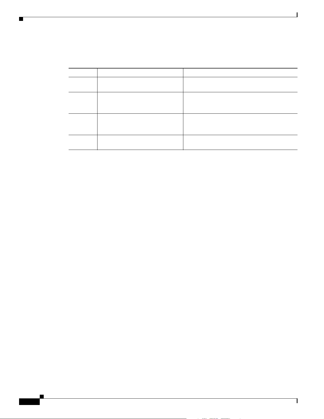
Organization
Organization
This document contains the following chapters:
Section Title Description
Chapter 1 Overview Describes the PA-2FEISL and its LED displays,
Chapter 2 Preparing for Installation Describes safety considerations, tools required,
Chapter 3 Removing and Installing
Chapter 4 Configuring the PA-2FEISL Provides instructions for configuring your port
Port Adapters
Preface
cables, and receptacles.
and procedures you should perform before the
actual installation.
Describes the procedures for installing and
removing PA-2FEISL port adapters in the
supported platforms.
adapter on the supported platforms.
Related Documentation
Your router and the Cisco IOS software running on it contain extensive features and functionality, which
are documented in the following resources:
• Cisco IOS software:
For configuration information and support, refer to the modular configuration and modular
command reference publications in the Cisco IOS software configuration documentation set that
corresponds to the software release installed on your Cisco hardware. For software advisor and other
helpful links, go to the following URL:
http://www.cisco.com/univercd/cc/td/doc/product/core/7202/7200link.htm
• Cisco 7100 series routers:
–
For hardware installation and maintenance information, refer to the Cisco 7100 Series VPN
Router Installation and Configuration Guide .
–
For information on setting up a Virtual Private Network, refer to the Cisco 7100 Series VPN
Configuration Guide.
• Cisco 7200 series routers:
–
For port adapter hardware and memory configuration guidelines, refer to the Cisco 7200 Series
Port Adapter Hardware Configuration Guidelines.
–
For hardware installation and maintenance information (including the Cisco 7206 or
Cisco 7206VXR as a router shelf in a Cisco AS5800 Universal Access Server), refer to the
Cisco 7200 Series Router Hardware Installation and COnfiguration Guide.
• Cisco 7200 VXR routers:
vi
For hardware installation and maintenance information, refer to the Cisco 7200 VXR Installation
and Configuration Guide.
• Cisco uBR7200 series routers:
For hardware installation and maintenance information, refer to the Cisco uBR7200 Series
Universal Broadband Router Hardware Installation Guide t.
PA-2FEISL 100BASE-T Fast Ethernet/ISL Port Adapter Installation and Configuration
OL-3475-02
Page 7

Preface
• VIP2 in Cisco 7000 series and Cisco 7500 series routers:
For hardware installation and maintenance information, refer to the following publications:
–
The installation and configuration guides for the Cisco 7000 series or Cisco 7500 series router
–
Second-Generation Versatile Interface Processor (VIP2) Installation and Configuration
• For International agency compliance, safety, and statutory information for WAN interfaces:
–
Site Preparation and Safety Guide
–
Regulatory Compliance and Safety Information for the Cisco 7000 Series Routers
–
Regulatory Compliance and Safety Information for Cisco 7100 Series VPN Routers
–
Regulatory Compliance and Safety Information for the Cisco 7200 Series Routers
–
Regulatory Compliance and Safety Information for Cisco uBR7200 Series Universal Broadband
Routers
–
Regulatory Compliance and Safety Information for the Cisco 7500 Series Routers
Obtaining Documentation
Obtaining Documentation
Cisco documentation and additional literature are available on Cisco.com. Cisco also provides several
ways to obtain technical assistance and other technical resources. These sections explain how to obtain
technical information from Cisco Systems.
Cisco.com
You can access the most current Cisco documentation on the World Wide Web at this URL:
http://www.cisco.com/univercd/home/home.htm
You can access the Cisco website at this URL:
http://www.cisco.com
International Cisco websites can be accessed from this URL:
http://www.cisco.com/public/countries_languages.shtml
Ordering Documentation
You can find instructions for ordering documentation at this URL:
http://www.cisco.com/univercd/cc/td/doc/es_inpck/pdi.htm
You can order Cisco documentation in these ways:
• Registered Cisco.com users (Cisco direct customers) can order Cisco product documentation from
the Ordering tool:
OL-3475-02
http://www.cisco.com/en/US/partner/ordering/index.shtml
• Nonregistered Cisco.com users can order documentation through a local account representative by
calling Cisco Systems Corporate Headquarters (California, USA) at 408 526-7208 or, elsewhere in
North America, by calling 800 553-NETS (6387).
PA-2FEISL 100BASE-T Fast Ethernet/ISL Port Adapter Installation and Configuration
vii
Page 8

Documentation Feedback
Documentation Feedback
You can submit e-mail comments about technical documentation to bug-doc@cisco.com.
You can submit comments by using the response card (if present) behind the front cover of your
document or by writing to the following address:
Cisco Systems
Attn: Customer Document Ordering
170 West Tasman Drive
San Jose, CA 95134-9883
We appreciate your comments.
Obtaining Technical Assistance
For all customers, partners, resellers, and distributors who hold valid Cisco service contracts, the Cisco
Technical Assistance Center (TAC) provides 24-hour-a-day, award-winning technical support services,
online and over the phone. Cisco.com features the Cisco TAC website as an online starting point for
technical assistance. If you do not hold a valid Cisco service contract, please contact your reseller.
Preface
Cisco TAC Website
The Cisco TAC website provides online documents and tools for troubleshooting and resolving technical
issues with Cisco products and technologies. The Cisco TAC website is available 24 hours a day, 365
days a year. The Cisco TAC website is located at this URL:
http://www.cisco.com/tac
Accessing all the tools on the Cisco TAC website requires a Cisco.com user ID and password. If you
have a valid service contract but do not have a login ID or password, register at this URL:
http://tools.cisco.com/RPF/register/register.do
Opening a TAC Case
Using the online TAC Case Open Tool is the fastest way to open P3 and P4 cases. (P3 and P4 cases are
those in which your network is minimally impaired or for which you require product information.) After
you describe your situation, the TAC Case Open Tool automatically recommends resources for an
immediate solution. If your issue is not resolved using the recommended resources, your case will be
assigned to a Cisco TAC engineer. The online TAC Case Open Tool is located at this URL:
http://www.cisco.com/tac/caseopen
For P1 or P2 cases (P1 and P2 cases are those in which your production network is down or severely
degraded) or if you do not have Internet access, contact Cisco TAC by telephone. Cisco TAC engineers
are assigned immediately to P1 and P2 cases to help keep your business operations running smoothly.
viii
To open a case by telephone, use one of the following numbers:
Asia-Pacific: +61 2 8446 7411 (Australia: 1 800 805 227)
EMEA: +32 2 704 55 55
USA: 1 800 553-2447
PA-2FEISL 100BASE-T Fast Ethernet/ISL Port Adapter Installation and Configuration
OL-3475-02
Page 9

Preface
For a complete listing of Cisco TAC contacts, go to this URL:
http://www.cisco.com/warp/public/687/Directory/DirTAC.shtml
TAC Case Priority Definitions
To ensure that all cases are reported in a standard format, Cisco has established case priority definitions.
Priority 1 (P1)—Your network is “down” or there is a critical impact to your business operations. You
and Cisco will commit all necessary resources around the clock to resolve the situation.
Priority 2 (P2)—Operation of an existing network is severely degraded, or significant aspects of your
business operation are negatively affected by inadequate performance of Cisco products. You and Cisco
will commit full-time resources during normal business hours to resolve the situation.
Priority 3 (P3)—Operational performance of your network is impaired, but most business operations
remain functional. You and Cisco will commit resources during normal business hours to restore service
to satisfactory levels.
Priority 4 (P4)—You require information or assistance with Cisco product capabilities, installation, or
configuration. There is little or no effect on your business operations.
Obtaining Additional Publications and Information
Obtaining Additional Publications and Information
Information about Cisco products, technologies, and network solutions is available from various online
and printed sources.
• Cisco Marketplace provides a variety of Cisco books, reference guides, and logo merchandise. Go
to this URL to visit the company store:
http://www.cisco.com/go/marketplace/
• The Cisco Product Catalog describes the networking products offered by Cisco Systems, as well as
ordering and customer support services. Access the Cisco Product Catalog at this URL:
http://cisco.com/univercd/cc/td/doc/pcat/
• Cisco Press publishes a wide range of general networking, training and certification titles. Both new
and experienced users will benefit from these publications. For current Cisco Press titles and other
information, go to Cisco Press online at this URL:
http://www.ciscopress.com
• Packet magazine is the Cisco quarterly publication that provides the latest networking trends,
technology breakthroughs, and Cisco products and solutions to help industry professionals get the
most from their networking investment. Included are networking deployment and troubleshooting
tips, configuration examples, customer case studies, tutorials and training, certification information,
and links to numerous in-depth online resources. You can access Packet magazine at this URL:
http://www.cisco.com/packet
• iQ Magazine is the Cisco bimonthly publication that delivers the latest information about Internet
business strategies for executives. You can access iQ Magazine at this URL:
http://www.cisco.com/go/iqmagazine
OL-3475-02
PA-2FEISL 100BASE-T Fast Ethernet/ISL Port Adapter Installation and Configuration
ix
Page 10

Obtaining Additional Publications and Information
• Internet Protocol Journal is a quarterly journal published by Cisco Systems for engineering
professionals involved in designing, developing, and operating public and private internets and
intranets. You can access the Internet Protocol Journal at this URL:
http://www.cisco.com/ipj
• Training—Cisco offers world-class networking training. Current offerings in network training are
listed at this URL:
http://www.cisco.com/en/US/learning/index.html
Preface
PA-2FEISL 100BASE-T Fast Ethernet/ISL Port Adapter Installation and Configuration
x
OL-3475-02
Page 11

Overview
This chapter describes the PA-2FEISL port adapter and contains the following sections:
• Port Adapter Overview, page 1-1
• Fast Ethernet Overview, page 1-2
• IEEE 802.3u 100BASE-T Specifications, page 1-3
• LEDs, page 1-4
• Cables, Connectors, and Pinouts, page 1-5
• Port Adapter Slot Locations on the Supported Platforms, page 1-7
• Identifying Interface Addresses, page 1-9
Port Adapter Overview
CHAPTER
1
The PA-2FEISL, shown in Figure 1-1, provides two 100-Mbps, 100BASE-T Fast Ethernet/ISL interfaces
for the VLAN transport over switch-to-switch backbone connections or switch-to-server data center
attachments. These port adapters provide an inter-VLAN bridging and routing functionality that network
administrators can use to deploy 100-Mbps Token Ring VLAN transport, 100-Mbps Ethernet VLAN
transport, and bridging or routing between the mixed LAN types using the same physical ISL trunk links.
Both full-duplex and half-duplex operation are supported for the PA-2FEISL. See the “Fast Ethernet
Overview” section on page 1-2 for additional information.
Both models of the PA-2FEISL (PA-2FEISL-TX and PA-2FEISL-FX) are shown in Figure 1-1 and
Figure 1-2.
Note Although the VIP2, and Catalyst RSM/VIP2 support online insertion and removal (OIR), individual
port adapters do not. To replace port adapters, you must first remove the VIP2 or Catalyst RSM/VIP2
from the chassis, and then replace port adapters as required.
Cisco 7100 series, Cisco 7200 series, and Cisco uBR7200 series routers support OIR of all port adapter
types.
OL-3475-02
PA-2FEISL 100BASE-T Fast Ethernet/ISL Port Adapter Installation and Configuration
1-1
Page 12

Fast Ethernet Overview
Chapter 1 Overview
Figure 1-1 PA-2FEISL-TX—Faceplate View
ENABLED
LINK
0
LINK
1
10983
Figure 1-2 PA-2FEISL-FX—Faceplate View
ENABLED
LINK
RX
TX
0
LINK
RX
TX
1
10984
You can install the PA-2FEISL in the following slots on the hardware platforms described in this
document:
• Cisco 7100 series routers—Port adapter slot 3 for the Cisco 7120 series and port adapter slot 4 for
the Cisco 7140 series
• VIP2-15, VIP2-20, and VIP2-40—Port adapter slot 0 and port adapter slot 1
• Cisco 7200 series routers—Any of the port adapter slots: 1 through 6 for the Cisco 7206 and the
Cisco 7206VXR, or 1 through 4 for the Cisco 7204
• Cisco uBR7200 series routers—Any of the port adapter slots: 1 and 2 for the Cisco uBR7246 and
Cisco uBR7246 VXR, or 1 for the Cisco uBR7223
Note Port adapters have a handle attached, but this handle is occasionally not shown in figures
to allow a full view of detail on the port adapter’s faceplate.
Fast Ethernet Overview
Each Fast Ethernet port on the PA-2FEISL-TX has an RJ-45 connector to attach to Category 5
unshielded twisted-pair (UTP) cable for 100BASE-TX. Each Fast Ethernet port on the PA-2FEISL-FX
has an SC-type fiber-optic connector for 100BASE-FX.
The term Ethernet is commonly used for all carrier sense multiple access/collision detection
(CSMA/CD) LANs that generally conform to Ethernet specifications, including Fast Ethernet under
IEEE 802.3u.
Note 100BASE-TX is intended for Environment A, and 100BASE-FX is intended for Environment B. Both
are described in the IEEE 802.3u standard.
IEEE 802.3u is well suited to applications where a local communication medium must carry sporadic,
occasionally heavy traffic at peak data rates. Stations on a CSMA/CD LAN can access the network at
any time. Before sending data, the station listens to the network to see if it is already in use. If it is in
use, the station waits until the network is not in use, then transmits. This process is known as half-duplex
operation. A collision occurs when two stations listen for network traffic, hear none, and transmit almost
simultaneously. When simultaneous transmission occurs, both transmissions are damaged and the
PA-2FEISL 100BASE-T Fast Ethernet/ISL Port Adapter Installation and Configuration
1-2
OL-3475-02
Page 13

Chapter 1 Overview
stations must retransmit. The stations detect the collision and use backoff algorithms to determine when
they should retransmit.
Both Ethernet and IEEE 802.3u are broadcast networks, which means that all stations see all
transmissions. Each station must examine received frames to determine whether it is the intended
destination and, if it is, pass the frame to a higher protocol layer for processing.
IEEE 802.3u specifies the following different physical layers for 100BASE-T:
• 100BASE-TX—100BASE-T, half- and full-duplex over Category 5 UTP, Electronics Industry
Association/Telecommunications Industry Association (EIA/TIA)–568-compliant cable
• 100BASE-FX—100BASE-T, half- and full-duplex over optical fiber
Each physical layer protocol has a name that summarizes its characteristics in the format speed/signaling
method/segment length, where speed is the LAN speed in megabits per second (Mbps), signaling method
is the signaling method used (either baseband or broadband), and segment length is the maximum length
between stations in hundreds of meters. Therefore, 100BASE-T specifies a 100-Mbps, baseband LAN
with maximum network segments.
IEEE 802.3u 100BASE-T Specifications
IEEE 802.3u 100BASE-T Specifications
This section provides specifications for IEEE 802.3u 100BASE-T. Table 1-1 provides cabling
specifications for 100BASE-TX Fast Ethernet transmission over UTP and foil twisted-pair (FTP), and
100BASE-FX Fast Ethernet over fiber-optic cables. It also summarizes IEEE 802.3u 100BASE-TX and
100BASE-FX physical characteristics. Also see Figure 1-3.
Table 1-1 Specifications and Connection Limits for 100BASE-TX and 100BASE-FX Transmission
Parameter 100BASE-TX
Cable specification Category 5
AWG
Maximum segment
3
length
(half-duplex)
Maximum segment
length (full-duplex)
Maximum network
100 m 412 m N/A
100 m 2000 m 10,000 m
3
200 m 272 m N/A
1
UTP2, 22 to 24
100BASE-FX
Multi-Mode
62.5/125 multimode optical fiber 9/125 micron single mode
100BASE-FX
Single Mode
optical fiber
length (half-duplex,
one repeater)
4
Data rate 100 Mbps 100 Mbps 100 Mbps
Signaling method 4B/5B block coded, scrambled,
with MLT-3 line coding
Connector RJ-45 (ISO/IEC
60603-7:-1990
4B/5B block coded, with NRZI
line coding
SC-type: dual simplex or single
duplex for RX and TX
4B/5B block coded, with NRZI
line coding
SC-type: dual simplex or single
duplex for RX and TX
Topology Star/hub Star/hub Star/hub
1. EIA/TIA-568 or EIA-TIA-568 TSB-36 compliant.
2. Cisco does not supply Category 5 UTP RJ-45 cables. However, they are available commercially.
3. Data Terminal Equipment (DTE to DTE), see Figure 1-3.
4. DTE to Repeater to DTE, see Figure 1-3.
OL-3475-02
PA-2FEISL 100BASE-T Fast Ethernet/ISL Port Adapter Installation and Configuration
1-3
Page 14
LEDs
Chapter 1 Overview
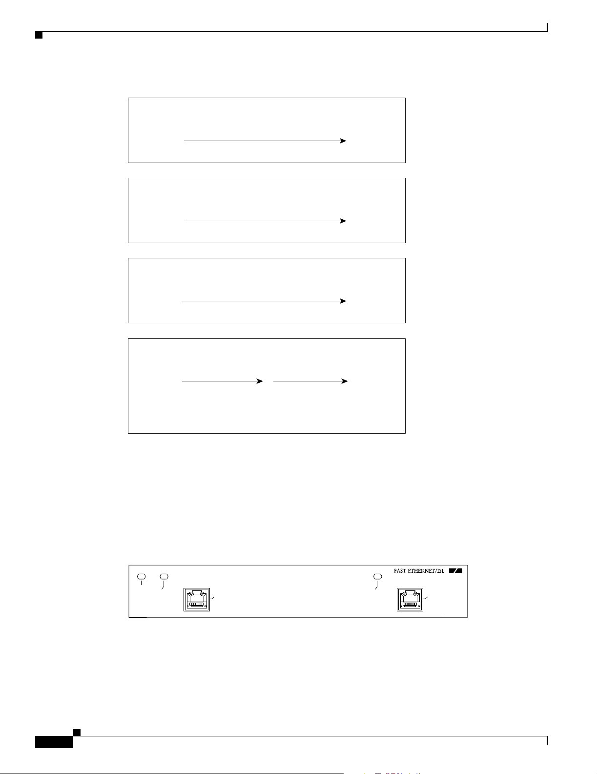
Figure 1-3 Maximum Segment and Network Lengths—100BASE--FX and 100BASE--TX
Maximum segment length, full duplex
100 m TX
DTEDTE*
2000 m FX–multimode
Maximum segment length, full duplex
10,000 m FX–single mode
DTEDTE
Maximum segment length, half duplex
100 m TX
DTEDTE
412 m FX
LEDs
Maximum network length, half duplex
200 m TX
DTEDTE R
(Repeater)
272 m FX**
**Because repeaters have more delay, total network length is shorter.
31703
*DTE = Data Terminal Equipment
The PA-2FEISL has an ENABLED LED, which is standard on all port adapters, and a LINK LED for
each of the ports. (See Figure 1-4.)
Figure 1-4 LEDs on the PA-2FEISL—Horizontal Orientation
ENABLED
LINK
0
LINK
1
10983
1-4
After system initialization, the ENABLED LED goes on to indicate that the port adapter has been
enabled for operation.
The following conditions must be met before the
• The PA-2FEISL is correctly connected and is receiving power.
PA-2FEISL 100BASE-T Fast Ethernet/ISL Port Adapter Installation and Configuration
PA-2FEISL is enabled:
OL-3475-02
Page 15
Chapter 1 Overview
• A valid system software image for the port adapter has been downloaded successfully.
• The system recognizes the PA-2FEISL or a VIP2 with a PA-2FEISL.
If any of the above conditions are not met, or if the initialization fails for other reasons, the enabled LED
does not go on.
Table 1 -2 lists port LED colors and indications.
Table 1-2 PA-2FEISL LEDs
LED Label Color State Meaning
ENABLED Green On Port adapter is enabled for operation.
LINK Green Blinking Port adapter is receiving a carrier signal from the network
1. When an RJ-45 or SC port is active.
Cables, Connectors, and Pinouts
The two interface receptacles on the PA-2FEISL are a single RJ-45 connection (on the PA-2FEISL-TX)
or a SC-type optical-fiber connection (on the PA-2FEISL-FX). Each connection supports IEEE 802.3u
interfaces compliant with the 100BASE-X and 100BASE-T standards. The RJ-45 connection does not
require an external transceiver.
Cables, Connectors, and Pinouts
1
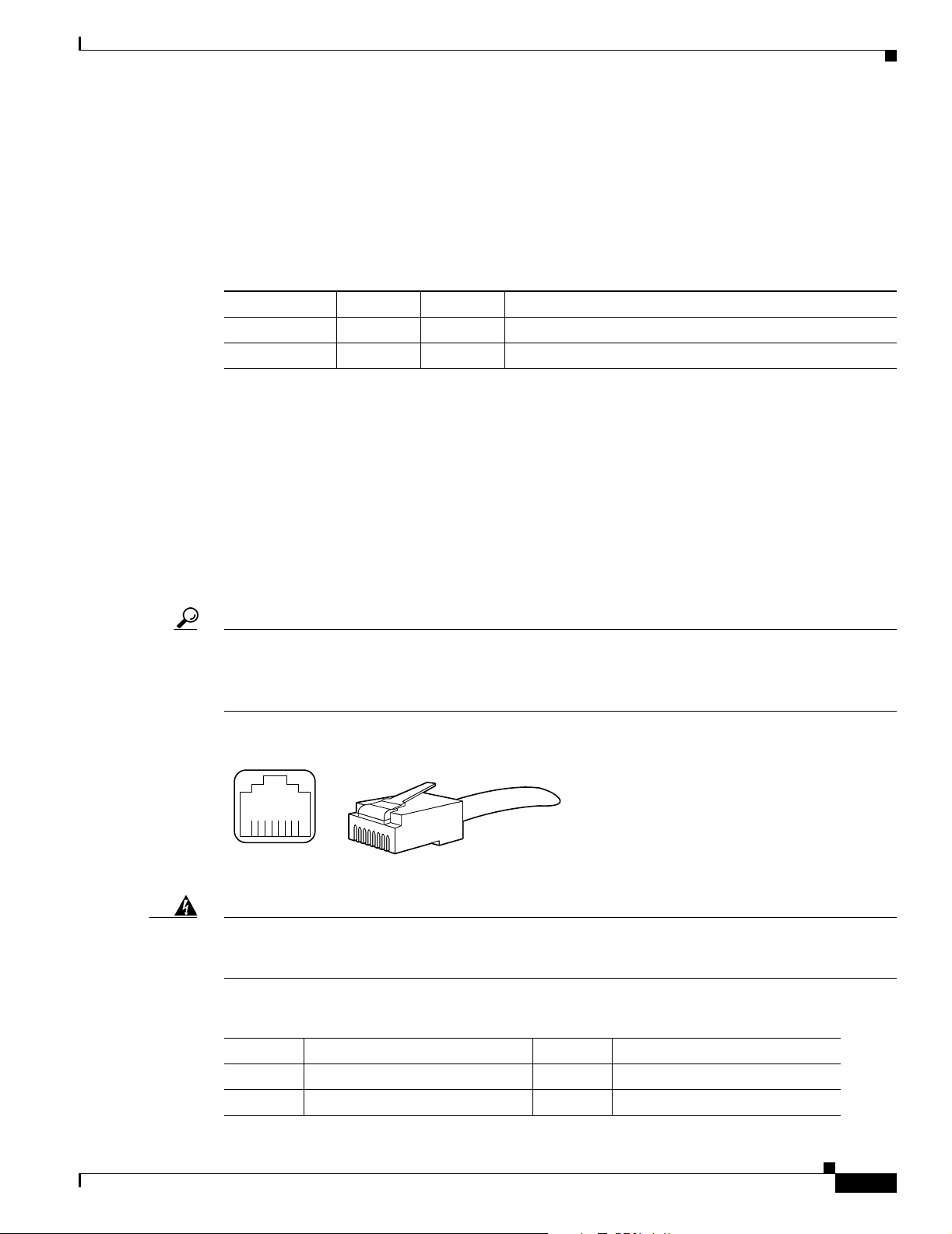
Figure 1-5 shows the RJ-45 cable connectors. Cisco does not supply Category 5 UTP RJ-45 cables; these
cables are available commercially. lists the pinouts and signals for the 2FEISL-TX RJ-45 connectors.
Tip Ports labeled “Ethernet,” “10BASE-T,” “Token Ring,” “Console,” and “AUX” are safety extra-low
voltage (SELV) circuits. SELV circuits should only be connected to other SELV circuits. Because the
Basic Rate Interface (BRI) circuits are treated like telephone-network voltage, avoid connecting the
SELV circuit to the telephone network voltage circuits.
Figure 1-5 PA-2FEISL-TX RJ-45 Connections—Plug and Receptacle
8 7 6 5 4 3 2 1
H2936
Statement 1021
Warning
RJ-45 connector
To avoid electric shock, do not connect safety extra-low voltage (SELV) circuits to telephone-network
voltage (TNV) circuits. LAN ports contain SELV circuits, and WAN ports contain TNV circuits. Some
LAN and WAN ports both use RJ-45 connectors. Use caution when connecting cables.
Table 1-3 FE-TX RJ-45 Connector Pinouts
OL-3475-02
Pin Description Pin Description
1 Receive Data + (RxD+) 3 Transmit Data + (TxD+)
2RxD– 6TxD–
PA-2FEISL 100BASE-T Fast Ethernet/ISL Port Adapter Installation and Configuration
1-5
Page 16
Cables, Connectors, and Pinouts
Note Referring to the RJ-45 pinout in Table 1 -3, proper common-mode line terminations should be used for
the unused Category 5, unshielded twisted-pair (UTP) cable pairs 4/5 and 7/8. Common-mode
termination reduces the contributions to electromagnetic interference (EMI) and susceptibility to
common-mode sources. Wire pairs 4/5 and 7/8 are actively terminated in the RJ-45, 100BASE-TX port
circuitry in the PA-2FEISL-TX.
Depending on your RJ-45 interface cabling requirements, use the pinouts in Figure 1-6 and Figure 1-7.
Figure 1-6 Straight-Through Cable Pinout—PA-2FEISL-TX RJ-45 Connection to a Hub or Repeater
5 TxD+
6 TxD–
Chapter 1 Overview
Hub or repeaterFEIP
5 RxD+
6 RxD–
3 RxD+
4 RxD–
3 TxD+
4 TxD–
H3137
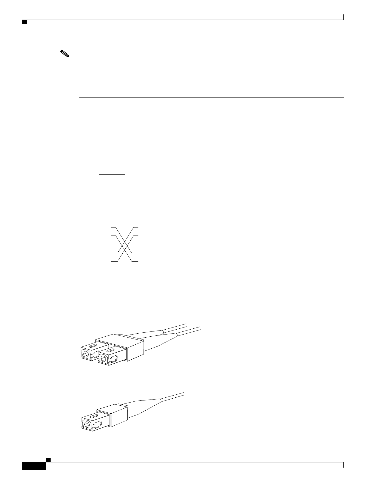
Figure 1-7 Crossover Cable Pinout—PA-2FEISL-TX RJ-45 Connections Between Hubs and Switches
Hub or LAN switch
3 TxD+
6 TxD–
1 RxD+
2 RxD–
Hub or LAN switch
3 TxD+
6 TxD–
1 RxD+
2 RxD–
H3138
Figure 1-8 shows the duplex SC connector (one required for both transmit and receive), and shows the
simplex SC connector (two required, one for each transmit and receive) used for PA-2FEISL-FX
optical-fiber connections. These multimode optical-fiber cables are commercially available, and are not
available from Cisco.
Figure 1-8 PA-2FEISL-FX Duplex SC Connector
1-6
H2214
Figure 1-9 PA-2FEISL-FX Simplex SC Connector
H2399
PA-2FEISL 100BASE-T Fast Ethernet/ISL Port Adapter Installation and Configuration
OL-3475-02
Page 17
Chapter 1 Overview
Port Adapter Slot Locations on the Supported Platforms
Port Adapter Slot Locations on the Supported Platforms
Cisco 7100 Series Routers Slot Numbering
The PA-2FEISL can be installed in port adapter slot 3 in Cisco 7120 series routers, and in port adapter
slot 4 in Cisco 7140 series routers. Figure 1-10 shows a Cisco 7120 with a port adapter installed in slot 3.
Figure 1-11 shows a Cisco 7140 with a port adapter installed in slot 4.
Figure 1-10 Port Adapter Slots in the Cisco 7100 Series Router —Cisco 7120 Series
Slot 3
5
I
EN
RX
CEL CAR ALM
E3
RXTX
Slot 1
FE 0 / 0 FE
0 / 1
Slot 0
ACT
LNK0LNK
Slot 4Slot 5
ACT
1
SLOT 0 SLOT 1
CONS
PWR
SYS
RDY
AUX
7120 - AE3
0
2
Slot 2
Figure 1-11 Port Adapter Slots in the Cisco 7100 Series Router—Cisco 7140 Series
Slot 4Slot 5 Slot 3
A
C
K
O
D
C
K
O
T
F
O
PWR
0
A
C
K
O
SYS
RDY
D
C
K
O
AUX
T
F
O
2
155 - MM
TX
SLOT 0 SLOT 1
CONS
7140 - 2MM3
Slot 2
BOOT
ERROR
5
155 - MM
RX
RX
I
EN
CEL CAR ALM
TX
RESETSM-ISM
EN
Slot 1
FE 0 / 0 FE
EN
RX
CEL CAR ALM
ACT
ACT
LNK0LNK
1
0 / 1
RX
Slot 0
18498
18499
Cisco 7200 Series and Cisco uBR7200 Series Routers Slot Numbering
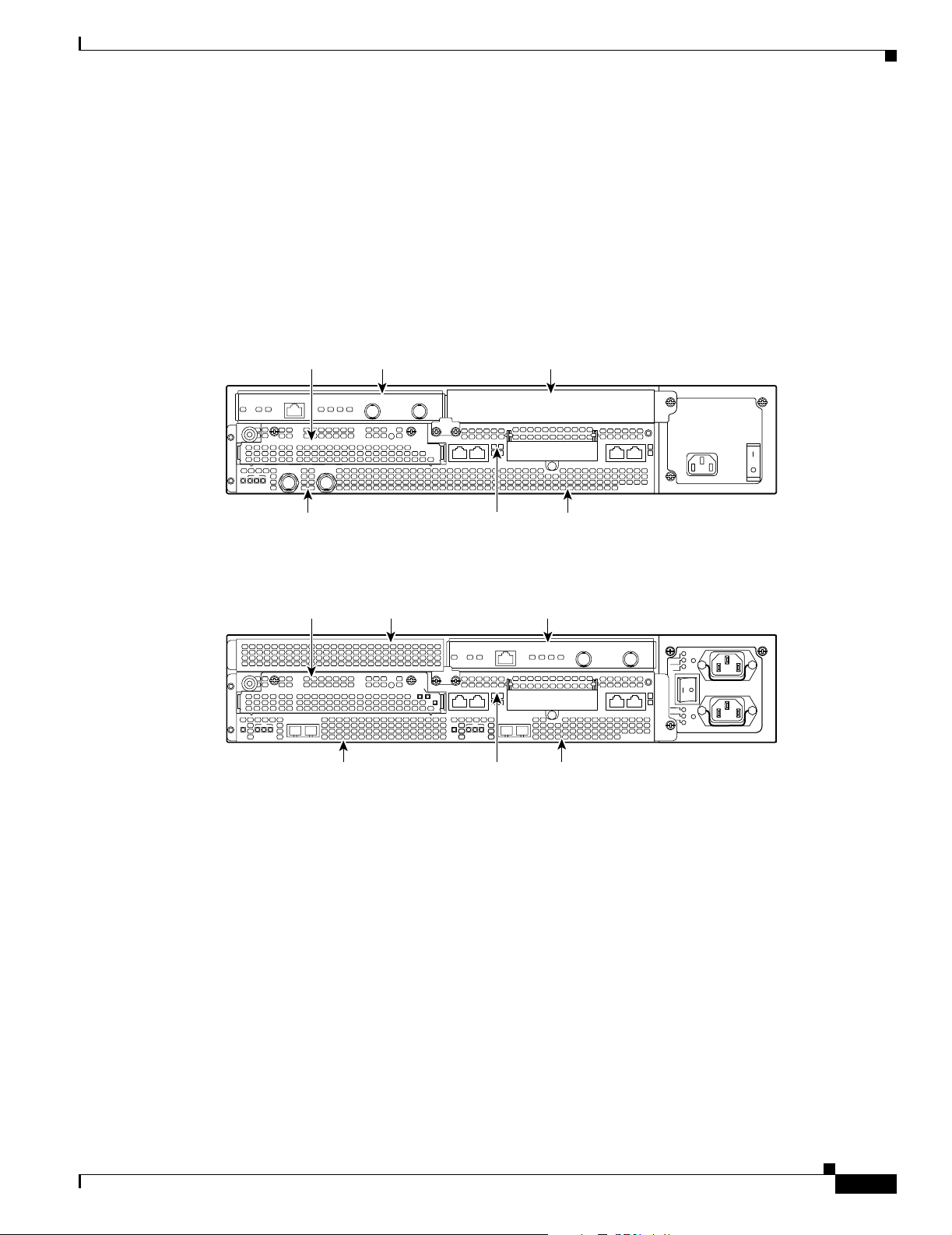
Figure 1-12 shows a Cisco 7206 with port adapters installed. In the Cisco 7206 (including the
Cisco 7206 and Cisco 7206VXR as router shelves in a Cisco AS5800 Universal Access Server),
port adapter slot 1 is in the lower left position, and port adapter slot 6 is in the upper right position. (The
Cisco 7202 and Cisco 7204 are not shown; however, the PA-2FEISL can be installed in any available
port adapter slot.)
PA-2FEISL 100BASE-T Fast Ethernet/ISL Port Adapter Installation and Configuration
OL-3475-02
1-7
Page 18
Port Adapter Slot Locations on the Supported Platforms
Figure 1-12 Port Adapter Slots in the Cisco 7206
Cisco 7200
Series
Chapter 1 Overview
G
IN
R
N
E
K
O
T
6
3
2
1
5
T
B
0
1
T
E
N
R
E
H
T
K
D
E
L
B
A
3
N
E
EN
1
ENABLED
3
2
1
0
LIN
3
1
2
0
4
3
2
1
0
EJECT
PCMCIA
E
.35
-V
L
IA
R
E
S
7
6
5
SLOT 1
FE MII
I
I
M
SLOT 0
E
0
FAST ETHERNET
5
K
4
J
II
IN
R
L
X
R
1
M
0
X
X
R
T
2
FAST ETHERNET INPUT/OUTPUT CONTROLLER
X
X
X
T
R
T
3
ENABLED
N
E
X
X
T
R
0
5
4
-
J
R
R
5
5
4
4
W
-
-
J
P
J
K
R
N
N
R
K
N
O
I
E
1
O
L
4
L
F
B
0
1
-
T
E
N
R
E
H
T
E
X
X
T
R
2
4
0
28329
Port adapter slot 5
Port adapter slot 3
Port adapter slot 1
Port adapter slot 2
Port adapter slot 6
Port adapter slot 4
Port adapter slot 0
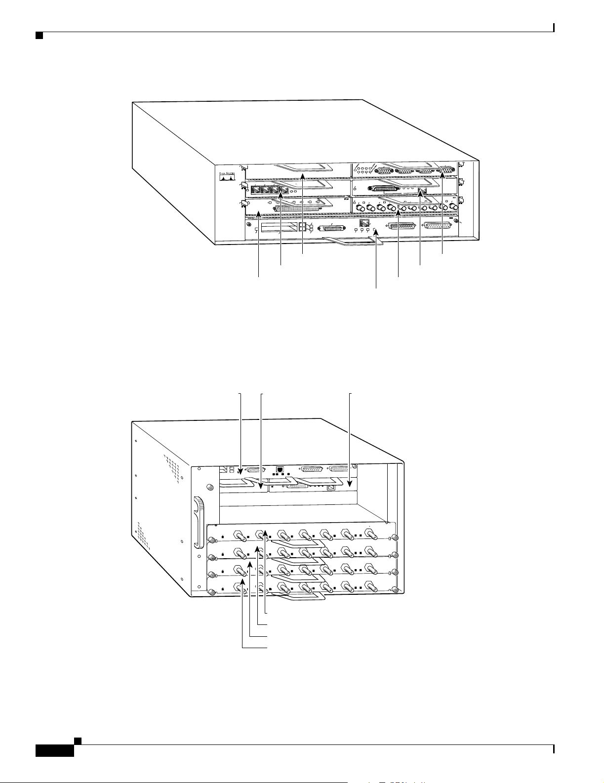
Figure 1-13 shows the slot numbering of port adapters in a Cisco uBR7246 series router. The port
adapter slots are numbered slot 1 and slot 2 for the Cisco uBR7246 and slot 1 for the Cisco uBR7223.
(Slot 0 is always reserved for the Fast Ethernet port on the I/O controller—if present.)
Figure 1-13 Port Adapter Slots in the Cisco uBR7246
Port adapter slot 0
(I/O controller)
ENABLED
ENABLED
ENABLED
ENABLED
0
US
0
US
0
US
0
US
Port adapter slot 1
(blank)
2
1
US
1
US
1
US
1
US
US
US
2
US
2
US
2
US
Port adapter slot 2
CI6
uBR - M
5
4
3
US
US
DS
CI6
uBR - M
5
US
DS
CI6
uBR - M
5
US
DS
CI6
uBR - M
5
US
DS
H11323
1-8
Cable modem card slot 3
Cable modem card slot 4
Cable modem card slot 5
Cable modem card slot 6
PA-2FEISL 100BASE-T Fast Ethernet/ISL Port Adapter Installation and Configuration
OL-3475-02
Page 19

Chapter 1 Overview
Cisco VIP2 Slot Numbering
Figure 1-14 shows a VIP motherboard with installed port adapters. With the motherboard oriented as
shown in Figure 1-14, the left port adapter is in port adapter slot 0, and the right port adapter is in
port adapter slot 1. The slot numbering is the same for the Catalyst RSM/VIP2-15 or VIP2-40. The slots
are always numbered 0 and 1.
Figure 1-14 VIP Motherboard with Two Port Adapters Installed—Horizontal Orientation
Identifying Interface Addresses
Port adapter slot 0
Port adapter
handles not
shown
Identifying Interface Addresses
This section describes how to identify interface addresses for the PA-2FEISL in supported platforms.
Interface addresses specify the actual physical location of each interface on a router or switch.
Interfaces on the PA-2FEISL installed in a router maintain the same address regardless of whether other
port adapters are installed or removed. However, when you move a port adapter to a different slot, the
first number in the interface address changes to reflect the new port adapter slot number.
Interfaces on a PA-2FEISL installed in a VIP2 maintain the same address regardless of whether other
interface processors are installed or removed. However, when you move a VIP2 to a different slot, the
interface processor slot number changes to reflect the new interface processor slot.
Note Interface ports are numbered from left to right starting with 0.
Port adapter slot 1
28327
OL-3475-02
Table 1 -4 explains how to identify interface addresses.
PA-2FEISL 100BASE-T Fast Ethernet/ISL Port Adapter Installation and Configuration
1-9
Page 20

Chapter 1 Overview
Identifying Interface Addresses
Table 1-4 Identifying Interface Addresses
Platform Interface Address Format Numbers Syntax
Cisco 7120 series routers Port-adapter-slot-number/interface-port-number Port adapter slot—always 3
3/0
Interface port—0 through 1
Cisco 7140 series routers Port-adapter-slot-number/interface-port-number Port adapter slot—always 4
4/0
Interface port—0 through 1
Cisco 7200 series routers Port-adapter-slot-number/interface-port-number Port adapter slot—0 through 6
1/0
(depends on the number of slots
in the router)
1
Interface port—0 through 1
1
Cisco uBR7223 router Port-adapter-slot-number/interface-port-number Port adapter slot—always 1
1/0
Interface port—0 through 1
Cisco uBR7246 router Port-adapter-slot-number/interface-port-number Port adapter slot—always 1
or 2
1
1/0
Interface port—0 through 1
VIP2 in Cisco 7000 series
or Cisco 7500 series
routers
Interface-processor-slot-number/port-adapter-slotnumber/interface-port-number
Interface processor slot—0
through 12 (depends on the
number of slots in the router)
1/1/0
Port adapter slot—always 0 or 1
Interface port—0 through 1
1. Port adapter slot 0 is reserved for the Fast Ethernet port on the I/O controller (if present).
Cisco 7100 Series Addresses
This section describes how to identify the interface addresses used for the PA-2FEISL in Cisco 7100
series routers. The interface address is composed of a two-part number in the format
port-adapter-slot-number/interface-port-number. See Table 1-4 for the interface address format.
Cisco 7200 Series and Cisco uBR7200 Series Addresses
This section describes how to identify the interface addresses used for the PA-2FEISL in Cisco 7200
series routers or Cisco uBR7200 series routers. The interface address is composed of a two-part number
in the format port-adapter-slot-number/interface-port-number. See Tab l e 1-4 for the interface address
format.
In Cisco 7200 series routers, port adapter slots are numbered from the lower left to the upper right,
beginning with port adapter slot 1 and continuing through port adapter slot 2 for the Cisco 7202, slot 4
for the Cisco 7204 and Cisco 7204VXR, and slot 6 for the Cisco 7206 and Cisco 7206VXR. (Port
adapter slot 0 is reserved for the optional Fast Ethernet port on the I/O controller—if present.)
Figure 1-12 shows the interfaces of a PA-2FEISL port adapter in port adapter slot 1 of the Cisco 7206
router.
1-10
The interface addresses of the interfaces on the PA-2FEISL in port adapter slot 1 are 1/0 through 1/1
(port adapter slot 1 and interfaces 0 through 1). If the PA-2FEISL was in port adapter slot 4, these same
interfaces would be numbered 4/0 through 4/1 (port adapter slot 4 and interfaces 0 through 1).
PA-2FEISL 100BASE-T Fast Ethernet/ISL Port Adapter Installation and Configuration
OL-3475-02
Page 21

Chapter 1 Overview
Figure 1-13 shows port adapters installed in slot 1 and slot 2 of a Cisco uBR7246 router. The
port adapter slots are numbered slot 1 and slot 2 for the Cisco uBR7246, and slot 1 for the
Cisco uBR7223 and the Cisco uBR7246 VXR. (Slot 0 is always reserved for the Fast Ethernet port on
the I/O controller—if present.) The individual interfaces always begin with 0. The number of additional
interfaces depends on the number of interface ports on a port adapter.
The interface addresses of the interfaces on a PA-2FEISL in port adapter slot 2 are 2/0 and 2/1
(port adapter slot 2 and interfaces 0 and 1). If the PA-2FEISL was in port adapter slot 1, these same
interfaces would be numbered 1/0 and 1/1 (port adapter slot 1 and interfaces 0 and 1).
VIP2 Interface Addresses
This section describes how to identify the interface addresses used for the PA-2FEISL on a VIP2 in
Cisco 7000 series and Cisco 7500 series routers.
Note Although the processor slots in the 7-slot Cisco 7000 and Cisco 7507 and 13-slot Cisco 7513 and
Cisco 7576 are vertically oriented and those in the 5-slot Cisco 7010 and Cisco 7505 are horizontally
oriented, all Cisco 7000 series and Cisco 7500 series routers use the same method for slot and port
numbering.
Identifying Interface Addresses
See Table 1-4 for the interface address format. The interface address is composed of a three-part number
in the format interface-processor-slot number/port-adapter-slot-number/interface-port- number.
Figure 1-15 shows a sample Cisco 7505 system. The interface addresses of the PA-2FEISL are 3/1/0
through 3/1/1). If the port adapter was in port adapter slot 0 on the VIP2, these same interface addresses
would be numbered 3/0/0 through 3/0/1.
If you remove the VIP2 with the PA- 2 FE IS L (shown in Figure 1-15) from interface processor slot 3 and
install it in interface processor slot 2, the interface addresses become 2/1/0 through 2/1/1.
Figure 1-15 Fast Ethernet/ISL Interface Port Number Example—Cisco 7505
3/0/0 and 3/0/1 (PA-2FEISL-TX port adapter)
R
O
S
S
E
C
O
R
P
H
C
T
I
W
S
E
T
U
O
T
L
A
T
C
1
E
T
J
E
L
A
M
R
O
N
0
ENABLED
LINK
O
L
0
S
T
O
L
S
H
T
E
T
S
A
F
LINK
T
H
E
S
U
E
P
R
C
L
/IS
T
E
N
R
E
1
R
E
.
L
X
O
U
S
A
N
O
C
Slot 3
Slot 2
Slot 1
Interface
processor
slots
Slot 0
12063
OL-3475-02
Note If you remove the PA-2FEISL-equipped VIP2 (shown in Figure 1-15) from interface processor slot 3 and
install it in interface processor slot 2, the interface addresses become 2/1/0 through 2/1/1.
PA-2FEISL 100BASE-T Fast Ethernet/ISL Port Adapter Installation and Configuration
1-11
Page 22

Identifying Interface Addresses
Chapter 1 Overview
1-12
PA-2FEISL 100BASE-T Fast Ethernet/ISL Port Adapter Installation and Configuration
OL-3475-02
Page 23

Preparing for Installation
This chapter describes the general equipment, safety, and site preparation requirements for installing the
PA-2FEISL port adapter. This chapter contains the following sections:
• Required Tools and Equipment, page 2-1
• Software and Hardware Requirements, page 2-1
• Safety Guidelines, page 2-3
• FCC Class A Compliance, page 2-10
Required Tools and Equipment
You need the following tools and parts to install a port adapter. If you need additional equipment, contact
a service representative for ordering information.
CHAPTER
2
• PA-2FEISL-TX(=) or PA-2FEISL-FX(=) port adapter.
• VIP2 (for installation in the Cisco 7000 series or Cisco 7500 series chassis only). (For information
about the specific VIP model that supports the PA-2FEISL, see the “Software and Hardware
Requirements” section on page 2-1.)
• Cables appropriate for the port adapter’s interfaces (RJ-45 and multimode optical-fiber cables are
not available from Cisco; they are available from commercial cable vendors).
• Number 1 Phillips and a 3/16-inch, flat-blade screwdriver (for VIP2 installation only).
• Number 2 Phillips screwdriver.
• Your own ESD-prevention equipment or the disposable grounding wrist strap included with all
upgrade kits, field-replaceable units (FRUs), and spares.
• Antistatic mat.
• Antistatic container.
Software and Hardware Requirements
Table 2 -1 lists the recommended minimum Cisco IOS software release required to use the PA-2FEISL
in supported router platforms.
OL-3475-02
PA-2FEISL 100BASE-T Fast Ethernet/ISL Port Adapter Installation and Configuration
2-1
Page 24

Software and Hardware Requirements
Note Inter-Switch Link (ISL) features are not currently supported on the Cisco uBR7200 series. This
restriction is subject to change without notice.
Table 2-1 PA-2FEISL Software Requirements
Platform Recommended Minimum Cisco IOS Release
Cisco 7000 series and Cisco 7500 series
Chapter 2 Preparing for Installation
With VIP2-15(=), VIP2-20, or
•
Cisco IOS Release 11.3(4)T or a later release of Cisco IOS Release 11.3 T
VIP2-40(=)
Cisco 7100 series
Cisco 7120 series and Cisco 7140
•
series
Cisco 7200 series
Cisco 7204VXR and Cisco 7206VXR Cisco IOS Release 11.3(4)T or a later release of Cisco IOS Release 11.3 T
•
• Cisco 7204 and Cisco 7206 Cisco IOS Release 11.3(4)T or a later release of Cisco IOS Release 11.3 T
• Cisco 7202 Cisco IOS Release 11.3(4)T or a later release of Cisco IOS Release 11.3 T
• Cisco 7206 router shelf Cisco IOS Release 11.3(2)AA or a later release of Cisco IOS Release 11.3AA
Cisco uBR7200 series
Cisco uBR7246, Cisco uBR7246
•
VXR, and Cisco uBR7223
Cisco IOS Release 12.0(4)XE or a later release of Cisco IOS Release 12.0 XE
Cisco IOS Release 12.0(5)T or a later release of Cisco IOS Release 12.0 T
Cisco IOS Release 12.0(5)T or a later release of Cisco IOS Release 12.0 T
Cisco IOS Release 12.0(7)SC or a later release of Cisco IOS Release 12.0T
Cisco IOS Release 12.0(7)XR or a later release of Cisco IOS Release 12.0T
For release note information on the PA-2FEISL, refer to the Cisco IOS software release note for the
version of Cisco IOS software that you are running.
Ensure that the following hardware requirements are met for your PA-2FEISL:
The PA-2FEISL-FX requires the following Network Processing Engine (NPE) models:
2-2
• NPE-150 (150-MHz network processor)—up to 128 MB of DRAM
• NPE-175 (200-MHz network processor)—up to 128 MB of DRAM
• NPE-200 (200-MHz network processor)—up to 128 MB of DRAM
• NPE-225 (262-MHz network processor)—up to 128 MB of DRAM
Note The NPE-100 does not support the PA-2FEISL in Cisco 7200 series routers.
• In Cisco 7000 series or Cisco 7500 series routers, the PA-2FEISL requires the following VIP2
models:
–
VIP2-15 (1 MB of SRAM, 8 MB of DRAM)
–
VIP2-20 (1 MB of SRAM, 16 MB of DRAM)
–
VIP2-40 (2 MB of SRAM, 32 MB of DRAM)
PA-2FEISL 100BASE-T Fast Ethernet/ISL Port Adapter Installation and Configuration
OL-3475-02
Page 25

Chapter 2 Preparing for Installation
Note This release of the PA-2FEISL is not supported on the VIP2-50. (This restriction is subject
Note The minimum recommended VIP2 model is a VIP2-15. The maximum transmission unit
Caution The VIP2 requires that Cisco 7000 series routers have the RSP7000 and RSP7000CI installed. The VIP2
will not operate properly with the Route Processor (RP), Switch Processor (SP), or Silicon Switch
Processor (SSP) installed in the Cisco 7000 series routers.
Checking Hardware and Software Compatibility
to change without notice.)
(MTU) sizes available for two PA-2FEISL port adapters on a VIP2 require the additional
VIP2 SRAM available on VIP2-15 models, or greater, to ensure adequate packet buffers.
The VIP2-15 can also be used if you only have one Fast Ethernet port adapter on a VIP2.
The VIP2-10 has certain configuration constraints because of its limited SRAM for packet
buffers; therefore, we do not recommend you use VIP2-10 with Fast Ethernet port adapters.
Checking Hardware and Software Compatibility
To check the minimum software requirements of Cisco IOS software with the hardware installed on your
router, Cisco maintains the Software Advisor tool on Cisco.com. This tool does not verify whether
modules within a system are compatible, but it does provide the minimum IOS requirements for
individual hardware modules or components.
Note Access to this tool is limited to users with Cisco.com login accounts.
To access Software Advisor, go to the following URL:
http://www.cisco.com/pcgi-bin/Support/CompNav/Index.pl.
Safety Guidelines
This section provides safety guidelines that you should follow when working with any equipment that
connects to electrical power or telephone wiring.
Safety Warnings
Safety warnings appear throughout this publication in procedures that, if performed incorrectly, might
harm you. A warning symbol precedes each warning statement.
OL-3475-02
PA-2FEISL 100BASE-T Fast Ethernet/ISL Port Adapter Installation and Configuration
2-3
Page 26

Safety Guidelines
Chapter 2 Preparing for Installation
Warning
Waarschuwing
Varoitus
IMPORTANT SAFETY INSTRUCTIONS
This warning symbol means danger. You are in a situation that could cause bodily injury. Before you
work on any equipment, be aware of the hazards involved with electrical circuitry and be familiar
with standard practices for preventing accidents. Use the statement number provided at the end of
each warning to locate its translation in the translated safety warnings that accompanied this
device.
Statement 1071
SAVE THESE INSTRUCTIONS
BELANGRIJKE VEILIGHEIDSINSTRUCTIES
Dit waarschuwingssymbool betekent gevaar. U verkeert in een situatie die lichamelijk letsel kan
veroorzaken. Voordat u aan enige apparatuur gaat werken, dient u zich bewust te zijn van de bij
elektrische schakelingen betrokken risico's en dient u op de hoogte te zijn van de standaard
praktijken om ongelukken te voorkomen. Gebruik het nummer van de verklaring onderaan de
waarschuwing als u een vertaling van de waarschuwing die bij het apparaat wordt geleverd, wilt
raadplegen.
BEWAAR DEZE INSTRUCTIES
TÄRKEITÄ TURVALLISUUSOHJEITA
Tämä varoitusmerkki merkitsee vaaraa. Tilanne voi aiheuttaa ruumiillisia vammoja. Ennen kuin
käsittelet laitteistoa, huomioi sähköpiirien käsittelemiseen liittyvät riskit ja tutustu
onnettomuuksien yleisiin ehkäisytapoihin. Turvallisuusvaroitusten käännökset löytyvät laitteen
mukana toimitettujen käännettyjen turvallisuusvaroitusten joukosta varoitusten lopussa näkyvien
lausuntonumeroiden avulla.
Attention
Warnung
SÄILYTÄ NÄMÄ OHJEET
IMPORTANTES INFORMATIONS DE SÉCURITÉ
Ce symbole d'avertissement indique un danger. Vous vous trouvez dans une situation pouvant
entraîner des blessures ou des dommages corporels. Avant de travailler sur un équipement, soyez
conscient des dangers liés aux circuits électriques et familiarisez-vous avec les procédures
couramment utilisées pour éviter les accidents. Pour prendre connaissance des traductions des
avertissements figurant dans les consignes de sécurité traduites qui accompagnent cet appareil,
référez-vous au numéro de l'instruction situé à la fin de chaque avertissement.
CONSERVEZ CES INFORMATIONS
WICHTIGE SICHERHEITSHINWEISE
Dieses Warnsymbol bedeutet Gefahr. Sie befinden sich in einer Situation, die zu Verletzungen führen
kann. Machen Sie sich vor der Arbeit mit Geräten mit den Gefahren elektrischer Schaltungen und
den üblichen Verfahren zur Vorbeugung vor Unfällen vertraut. Suchen Sie mit der am Ende jeder
Warnung angegebenen Anweisungsnummer nach der jeweiligen Übersetzung in den übersetzten
Sicherheitshinweisen, die zusammen mit diesem Gerät ausgeliefert wurden.
BEWAHREN SIE DIESE HINWEISE GUT AUF.
2-4
PA-2FEISL 100BASE-T Fast Ethernet/ISL Port Adapter Installation and Configuration
OL-3475-02
Page 27

Chapter 2 Preparing for Installation
Safety Guidelines
Avvertenza
Advarsel
Aviso
IMPORTANTI ISTRUZIONI SULLA SICUREZZA
Questo simbolo di avvertenza indica un pericolo. La situazione potrebbe causare infortuni alle
persone. Prima di intervenire su qualsiasi apparecchiatura, occorre essere al corrente dei pericoli
relativi ai circuiti elettrici e conoscere le procedure standard per la prevenzione di incidenti.
Utilizzare il numero di istruzione presente alla fine di ciascuna avvertenza per individuare le
traduzioni delle avvertenze riportate in questo documento.
CONSERVARE QUESTE ISTRUZIONI
VIKTIGE SIKKERHETSINSTRUKSJONER
Dette advarselssymbolet betyr fare. Du er i en situasjon som kan føre til skade på person. Før du
begynner å arbeide med noe av utstyret, må du være oppmerksom på farene forbundet med
elektriske kretser, og kjenne til standardprosedyrer for å forhindre ulykker. Bruk nummeret i slutten
av hver advarsel for å finne oversettelsen i de oversatte sikkerhetsadvarslene som fulgte med denne
enheten.
TA VARE PÅ DISSE INSTRUKSJONENE
INSTRUÇÕES IMPORTANTES DE SEGURANÇA
Este símbolo de aviso significa perigo. Você está em uma situação que poderá ser causadora de
lesões corporais. Antes de iniciar a utilização de qualquer equipamento, tenha conhecimento dos
perigos envolvidos no manuseio de circuitos elétricos e familiarize-se com as práticas habituais de
prevenção de acidentes. Utilize o número da instrução fornecido ao final de cada aviso para
localizar sua tradução nos avisos de segurança traduzidos que acompanham este dispositivo.
¡Advertencia!
Varning!
GUARDE ESTAS INSTRUÇÕES
INSTRUCCIONES IMPORTANTES DE SEGURIDAD
Este símbolo de aviso indica peligro. Existe riesgo para su integridad física. Antes de manipular
cualquier equipo, considere los riesgos de la corriente eléctrica y familiarícese con los
procedimientos estándar de prevención de accidentes. Al final de cada advertencia encontrará el
número que le ayudará a encontrar el texto traducido en el apartado de traducciones que acompaña
a este dispositivo.
GUARDE ESTAS INSTRUCCIONES
VIKTIGA SÄKERHETSANVISNINGAR
Denna varningssignal signalerar fara. Du befinner dig i en situation som kan leda till personskada.
Innan du utför arbete på någon utrustning måste du vara medveten om farorna med elkretsar och
känna till vanliga förfaranden för att förebygga olyckor. Använd det nummer som finns i slutet av
varje varning för att hitta dess översättning i de översatta säkerhetsvarningar som medföljer denna
anordning.
SPARA DESSA ANVISNINGAR
OL-3475-02
PA-2FEISL 100BASE-T Fast Ethernet/ISL Port Adapter Installation and Configuration
2-5
Page 28

Safety Guidelines
Chapter 2 Preparing for Installation
2-6
PA-2FEISL 100BASE-T Fast Ethernet/ISL Port Adapter Installation and Configuration
OL-3475-02
Page 29

Chapter 2 Preparing for Installation
Safety Guidelines
Aviso
Advarsel
INSTRUÇÕES IMPORTANTES DE SEGURANÇA
Este símbolo de aviso significa perigo. Você se encontra em uma situação em que há risco de lesões
corporais. Antes de trabalhar com qualquer equipamento, esteja ciente dos riscos que envolvem os
circuitos elétricos e familiarize-se com as práticas padrão de prevenção de acidentes. Use o
número da declaração fornecido ao final de cada aviso para localizar sua tradução nos avisos de
segurança traduzidos que acompanham o dispositivo.
GUARDE ESTAS INSTRUÇÕES
VIGTIGE SIKKERHEDSANVISNINGER
Dette advarselssymbol betyder fare. Du befinder dig i en situation med risiko for
legemesbeskadigelse. Før du begynder arbejde på udstyr, skal du være opmærksom på de
involverede risici, der er ved elektriske kredsløb, og du skal sætte dig ind i standardprocedurer til
undgåelse af ulykker. Brug erklæringsnummeret efter hver advarsel for at finde oversættelsen i de
oversatte advarsler, der fulgte med denne enhed.
GEM DISSE ANVISNINGER
OL-3475-02
PA-2FEISL 100BASE-T Fast Ethernet/ISL Port Adapter Installation and Configuration
2-7
Page 30

Safety Guidelines
Chapter 2 Preparing for Installation
2-8
PA-2FEISL 100BASE-T Fast Ethernet/ISL Port Adapter Installation and Configuration
OL-3475-02
Page 31

Chapter 2 Preparing for Installation
Electrical Equipment Guidelines
Follow these basic guidelines when working with any electrical equipment:
• Before beginning any procedures requiring access to the chassis interior, locate the emergency
power-off switch for the room in which you are working.
• Disconnect all power and external cables before moving a chassis; do not work alone when
potentially hazardous conditions exist.
• Never assume that power has been disconnected from a circuit; always check.
• Do not perform any action that creates a potential hazard to people or makes the equipment unsafe;
carefully examine your work area for possible hazards such as moist floors, ungrounded power
extension cables, and missing safety grounds.
Telephone Wiring Guidelines
Use the following guidelines when working with any equipment that is connected to telephone wiring or
to other network cabling:
Safety Guidelines
• Never install telephone wiring during a lightning storm.
• Never install telephone jacks in wet locations unless the jack is specifically designed for wet
locations.
• Never touch uninsulated telephone wires or terminals unless the telephone line has been
disconnected at the network interface.
• Use caution when installing or modifying telephone lines.
Preventing Electrostatic Discharge Damage
Electrostatic discharge (ESD) damage, which can occur when electronic cards or components are
improperly handled, results in complete or intermittent failures. Port adapters and processor modules
comprise printed circuit boards that are fixed in metal carriers. Electromagnetic interference (EMI)
shielding and connectors are integral components of the carrier. Although the metal carrier helps to
protect the board from ESD, use a preventive antistatic strap during handling.
Following are guidelines for preventing ESD damage:
• Always use an ESD wrist or ankle strap and ensure that it makes good skin contact.
• Connect the equipment end of the strap to an unfinished chassis surface.
• When installing a component, use any available ejector levers or captive installation screws to
properly seat the bus connectors in the backplane or midplane. These devices prevent accidental
removal, provide proper grounding for the system, and help to ensure that bus connectors are
properly seated.
OL-3475-02
• When removing a component, use any available ejector levers or captive installation screws to
release the bus connectors from the backplane or midplane.
• Handle carriers by available handles or edges only; avoid touching the printed circuit boards or
connectors.
• Place a removed board component-side-up on an antistatic surface or in a static shielding container.
If you plan to return the component to the factory, immediately place it in a static shielding
container.
PA-2FEISL 100BASE-T Fast Ethernet/ISL Port Adapter Installation and Configuration
2-9
Page 32

FCC Class A Compliance
• Avoid contact between the printed circuit boards and clothing. The wrist strap only protects
components from ESD voltages on the body; ESD voltages on clothing can still cause damage.
• Never attempt to remove the printed circuit board from the metal carrier.
Caution For safety, periodically check the resistance value of the antistatic strap. The measurement should be
between 1 and 10 megohms (Mohm).
FCC Class A Compliance
This equipment has been tested and found to comply with the limits for a Class A digital device, pursuant
to part 15 of the FCC rules. These limits are designed to provide reasonable protection against harmful
interference when the equipment is operated in a commercial environment. This equipment generates,
uses, and can radiate radio-frequency energy and, if not installed and used in accordance with the
instruction manual, may cause harmful interference to radio communications. Operation of this
equipment in a residential area is likely to cause harmful interference, in which case users will be
required to correct the interference at their own expense.
Chapter 2 Preparing for Installation
You can determine whether your equipment is causing interference by turning it off. If the interference
stops, it was probably caused by the Cisco equipment or one of its peripheral devices. If the equipment
causes interference to radio or television reception, try to correct the interference by using one or more
of the following measures:
• Turn the television or radio antenna until the interference stops.
• Move the equipment to one side or the other of the television or radio.
• Move the equipment farther away from the television or radio.
• Plug the equipment into an outlet that is on a different circuit from the television or radio. (That is,
make certain the equipment and the television or radio are on circuits controlled by different circuit
breakers or fuses.)
Note The PA-2FEISL port adapter has been designed to meet these requirements. Modifications to this product
that are not authorized by Cisco Systems, Inc., could void the various approvals and negate your
authority to operate the product.
2-10
PA-2FEISL 100BASE-T Fast Ethernet/ISL Port Adapter Installation and Configuration
OL-3475-02
Page 33

CHAPTER
3
Removing and Installing Port Adapters
This chapter describes how to remove the PA-2FEISL port adapter from supported platforms and also
how to install a new or replacement port adapter. This chapter contains the following sections:
• Handling Port Adapters, page 3-2
• Online Insertion and Removal, page 3-2
• Warnings and Cautions, page 3-3
• Port Adapter Removal and Installation, page 3-4
• Connecting a PA-2FEISL RJ-45 or SC Cable, page 3-10
Each port adapter circuit board is mounted to a metal carrier and is sensitive to electrostatic discharge
(ESD) damage.
Note When a port adapter slot is not in use, a blank port adapter must fill the empty slot to allow the router or
switch to conform to electromagnetic interference (EMI) emissions requirements and to allow proper
airflow across the port adapters. If you plan to install a new port adapter in a slot that is not in use, you
must first remove the blank port adapter.
OL-3475-02
Caution When powering off the router, wait a minimum of 30 seconds before powering it on again.
PA-2FEISL 100BASE-T Fast Ethernet/ISL Port Adapter Installation and Configuration
3-1
Page 34

Handling Port Adapters
Handling Port Adapters
Caution Always handle the port adapter by the carrier edges and handle; never touch the port adapter components
or connector pins. (See Figure 3-1.)
Figure 3-1 Handling a Port Adapter
Metal carrier
Printed circuit board
Chapter 3 Removing and Installing Port Adapters
H6420
Online Insertion and Removal
Several platforms support online insertion and removal (OIR) of port adapters; therefore, you do not
have to power down routers when removing and replacing a PA-2FEISL on Cisco 7100 series routers,
Cisco 7200 series routers, or Cisco uBR7200 series routers.
Although the VIP2 and the Catalyst RSM/VIP2 support online insertion and removal,
individual port adapters do not. To replace port adapters, you must first remove the VIP2 or
Catalyst RSM/VIP2 from the chassis and then install or replace port adapters as required. If a blank
port adapter is installed on the VIP2 or Catalyst RSM/VIP2 on which you want to install a new
port adapter, you must first remove the VIP2 or Catalyst RSM/VIP2 from the chassis and then remove
the blank port adapter.
Caution To prevent system problems, do not remove port adapters from the VIP2 or Catalyst RSM/VIP2
motherboard or attempt to install other port adapters on the motherboard when the system is operating.
To install or replace port adapters, first remove the VIP2 or Catalyst RSM/VIP2 from its interface
processor slot.
It is wise to gracefully shut down the system before removing a port adapter that has active traffic moving
through it. Removing a module while traffic is flowing through the ports can cause system disruption.
Once the module is inserted, the ports can be brought back up.
Note As you disengage the module from the router or switch, online insertion and removal (OIR)
administratively shuts down all active interfaces in the module.
3-2
OIR allows you to install and replace modules while the router is operating; you do not need to notify
the software or shut down the system power, although you should not run traffic through the module you
are removing while it is being removed. OIR is a method that is seamless to end users on the network,
maintains all routing information, and preserves sessions.
PA-2FEISL 100BASE-T Fast Ethernet/ISL Port Adapter Installation and Configuration
OL-3475-02
Page 35

Chapter 3 Removing and Installing Port Adapters
The following is a functional description of OIR for background information only; for specific
procedures for installing and replacing a module in a supported platform, refer to the “Port Adapter
Removal and Installation” section on page 3-4.
Each module has a bus connector that connects it to the router. The connector has a set of tiered pins in
three lengths that send specific signals to the system as they make contact with the module. The system
assesses the signals it receives and the order in which it receives them to determine if a module is being
removed from or introduced to the system. From these signals, the system determines whether to
reinitialize a new interface or to shut down a disconnected interface.
Specifically, when you insert a module, the longest pins make contact with the module first, and the
shortest pins make contact last. The system recognizes the signals and the sequence in which it receives
them.
When you remove or insert a module, the pins send signals to notify the system of changes. The router
then perfoms the following procedure:
1. Rapidly scans the system for configuration changes.
2. Initializes newly inserted port adapters or administratively shuts down any vacant interfaces.
3. Brings all previously configured interfaces on the module back to their previously installed state.
Any newly inserted interface is put in the administratively shutdown state, as if it was present (but
not configured) at boot time. If a similar module type is reinserted into a slot, its ports are configured
and brought online up to the port count of the originally installed module of that type.
Warnings and Cautions
Note Before you begin installation, read Chapter 2, “Preparing for Installation,” for a list of parts and tools
required for installation.
Warnings and Cautions
Observe the following warnings and cautions when installing or removing port adapters.
Caution Do not slide a port adapter all the way into the slot until you have connected all required cables. Trying
to do so disrupts normal operation of the router or switch.
Note If a port adapter lever or other retaining mechanism does not move to the locked position, the port
adapter is not completely seated in the midplane. Carefully pull the port adapter halfway out of the slot,
reinsert it, and move the port adapter lever or other mechanism to the locked position.
Caution To prevent jamming the carrier between the upper and the lower edges of the port adapter slot, and to
ensure that the edge connector at the rear of the port adapter mates with the connection at the rear of the
port adapter slot, make certain that the carrier is positioned correctly, as shown in the cutaway in the
following illustrations.
OL-3475-02
Warning
During this procedure, wear grounding wrist straps to avoid ESD damage to the card. Do not directly
touch the midplane with your hand or any metal tool, or you could shock yourself.
PA-2FEISL 100BASE-T Fast Ethernet/ISL Port Adapter Installation and Configuration
Statement 181
3-3
Page 36

Port Adapter Removal and Installation
Port Adapter Removal and Installation
In this section, these illustrations give step-by-step instructions on how to remove and install port
adapters.
• Cisco 7100 Series—Removing and Installing a Port Adapter, page 3-5
• Cisco 7200 Series—Removing and Installing a Port Adapter, page 3-6
• Cisco uBR7200 Series—Removing a Port Adapter, page 3-7
• Cisco uBR7200 Series—Installing a Port Adapter, page 3-8
• VIP2—Removing and Installing a Port Adapter, page 3-9
Chapter 3 Removing and Installing Port Adapters
3-4
PA-2FEISL 100BASE-T Fast Ethernet/ISL Port Adapter Installation and Configuration
OL-3475-02
Page 37

Chapter 3 Removing and Installing Port Adapters
Port Adapter Removal and Installation
Cisco 7100 Series—Removing and Installing a Port Adapter
Step 1
To remove the port adapter, use a number 2 Phillips screwdriver
to loosen the screws on the locking tab. Then slide the tab down
to the unlocked position.
Locked
Slot 3ESD plug
Unlocked
5
E3
I
RX
EN
CEL CAR ALM
RXTX
FE 0 / 0 FE
Step 2
Grasp the handle of the port adapter and pull the port adapter
from the router, about halfway out of its slot. If you are removing
a blank port adapter, pull the blank port adapter completely out
of the chassis slot.
Step 3
With the port adapter halfway out of the slot, disconnect all
cables from the port adapter.
Step 4
After disconnecting the cables, pull the port adapter from its
chassis slot.
Step 5
To insert the port adapter, carefully align the port adapter carrier
between the upper and the lower edges of the port adapter slot.
Guides
ACT
LNK0LNK
0 / 1
SLOT 0 SLOT 1
ACT
1
CONS
AUX
7120 - AE3
PWR
0
SYS
RDY
2
Step 6
With the port adapter halfway into the slot,
5
I
E
N
connect all required cables to the port adapter.
Step 7
After connecting all required cables, carefully slide the port
adapter all the way into the slot until the port adapter is seated in
the router midplane.
Step 8
PA-2FEISL 100BASE-T Fast Ethernet/ISL Port Adapter Installation and Configuration
OL-3475-02
R
C
VR
XM
TR
R
C
L
K
F
E
R
F
R
L
A
IS O
O
F
L
L
FE
0 /
3-5
Page 38

Chapter 3 Removing and Installing Port Adapters
Port Adapter Removal and Installation
Cisco 7200 Series—Removing and Installing a Port Adapter
Step 1
To remove the port adapter, place
the port adapter lever in the
unlocked position. (See A.) The
port adapter lever remains in the
unlocked position.
Step 2
Grasp the handle of the port adapter
and pull the port adapter from the
router, about halfway out of its slot.
If you are removing a blank port
adapter, pull the blank port adapter
completely out of the chassis slot.
Step 3
With the port adapter halfway out of
the slot, disconnect all cables from
the port adapter. After disconnecting
the cables, pull the port adapter
from its chassis slot.
Step 4
To insert the port adapter, carefully
align the port adapter carrier
between the upper and the lower
edges of the port adapter slot.
(See B.)
Step 5
Carefully slide the new port adapter
halfway into the port adapter slot.
(See B.)
Step 6
With the port adapter halfway into
the slot, connect all required cables
to the port adapter. After connecting
all required cables, carefully slide
the port adapter all the way into the
slot until the port adapter is seated
in the router midplane.
A
Note: This adapter
removal applies to any
port or service adapter.
Slot
guide
B
Cisco 7200
Series
Cisco 7200
Series
Port adapter lever
(locked position)
5
3
2
1
0
LINK
3
3
ENABLED
N
E
1
1
2
0
D
D
C
B
D
C
D
D
T
C
B
C
D
L
R
C
R
D
T
T
C
L
R
R
T
T
ENABLED
EJECT
PCMCIA
1
T
E
N
R
E
H
T
E
L
A
I
R
E
S
T
S
A
F
C
B
D
C
D
D
C
B
D
L
R
C
R
T
T
C
L
R
R
T
SLOT 1
FE MII
SLOT 0
0
T
D
B
0
E
L
B
A
N
E
D
C
MII
RJ45
RJ45
EN
EN
1O PWR
LINK
K
II
IN
L
M
0
FAST ETHERNET INPUT/OUTPUT CONTROLLER
CPU RESET
RJ-45
OK
T
E
N
R
E
H
T
E
T
S
A
F
5
4
J
R
4
2
0
G
N
I
R
N
E
K
O
T
6
3
2
1
Port adapter lever
(unlocked position)
G
N
I
R
N
E
K
O
T
6
3
2
1
5
3
2
1
0
LINK
3
3
ENABLED
1
1
2
0
ENABLED
EJECT
PCMCIA
1
T
E
N
R
E
H
T
E
FE MII
SLOT 1
SLOT 0
0
T
D
B
0
E
L
B
A
N
E
MII
RJ45
RJ45
EN
EN
1O PWR
LINK
K
I
N
I
I
L
M
0
FAST ETHERNET INPUT/OUTPUT CONTROLLER
CPU RESET
RJ-45
OK
T
E
N
R
E
H
T
E
T
S
A
F
5
4
J
R
4
2
27996
Step 7
After the port adapter is properly
seated, lock the port adapter lever.
(See A.)
PA-2FEISL 100BASE-T Fast Ethernet/ISL Port Adapter Installation and Configuration
3-6
OL-3475-02
Page 39

Chapter 3 Removing and Installing Port Adapters
Cisco uBR7200 Series—Removing a Port Adapter
Port Adapter Removal and Installation
Step 1
To remove the port adapter,
unlock the port adapter
retaining mechanism. The port
adapter lever remains in the
unlocked position.
Place the port adapter lever
(Cisco uBR7223, see A), or
the port adapter retention clip
(Cisco uBR7246 and Cisco
uBR7246 VXR, see B) in the
unlocked position. Either
mechanism remains in the
unlocked position.
Step 2
Grasp the handle of the port
adapter and pull the port
adapter from the router, about
halfway out of its slot.
If you are removing a blank
port adapter, pull the blank
port adapter completely out of
the chassis slot.
Port adapters
A
Note: This adapter
removal applies to any
port or service adapter.
Port adapters
Port adapter lever
(locked position)
Port adapter lever
(unlocked position)
Port adapter
retention clip
(locked position)
Step 3
With the port adapter halfway
out of the slot, disconnect all
cables from the port adapter.
After disconnecting the cables,
pull the port adapter from its
chassis slot.
OL-3475-02
Port adapter
retention clip
(unlocked position)
26523
B
PA-2FEISL 100BASE-T Fast Ethernet/ISL Port Adapter Installation and Configuration
3-7
Page 40

Port Adapter Removal and Installation
Cisco uBR7200 Series—Installing a Port Adapter
Step 1
To insert the port adapter, carefully
align the port adapter carrier
between the upper and the lower
edges of the port adapter slot.
Inside
slot guide
Metal carrier
Chapter 3 Removing and Installing Port Adapters
Step 2
Carefully slide the new port adapter
halfway into the port adapter slot.
Step 3
With the port adapter halfway into
the slot, connect all required cables
to the port adapter. After connecting
all required cables, carefully slide
the port adapter all the way into the
slot until the port adapter is seated in
the router midplane.
Step 4
After the port adapter is properly
seated, lock the port adapter lever or
retention clip, depending on your
system. (See illustration on
preceding page.)
PC board
26524
3-8
PA-2FEISL 100BASE-T Fast Ethernet/ISL Port Adapter Installation and Configuration
OL-3475-02
Page 41

Chapter 3 Removing and Installing Port Adapters
VIP2—Removing and Installing a Port Adapter
Note: You must first remove the VIP
from the chassis before removing a port
adapter from the VIP.
Step 1
To remove the port adapter, remove
the screw that secures the port
adapter (or blank port adapter).
(See A.)
Step 2
With the screw removed, grasp the
handle on the front of the port adapter
(or blank port adapter) and carefully pull
it out of its slot, away from the edge
connector at the rear of the slot. (See A.)
Step 3
To insert the port adapter, carefully align
the port adapter carrier between the
upper and the lower edges of the port
adapter slot. (See B.)
Step 4
Carefully slide the new port adapter into
the port adapter slot until the connector
on the port adapter is completely seated
in the connector at the rear of the port
adapter slot. (See B.)
A
Screw
B
Port Adapter Removal and Installation
Carrier
Upper edge
Lower edge
Step 5
Install the screw in the rear of the port
adapter slot on the VIP. Do not
overtighten the screw. (See A.)
Step 6
Carefully slide the VIP motherboard into
the interface processor slot until the
connectors at the rear of the VIP are
completely seated in the connectors at
the rear of the interface processor slot.
Use the ejector levers to seat the VIP in
the interface processor slot. Tighten the
captive installation screws on the VIP.
(See C.)
Captive
installation
screw
C
T
L
A
T
C
1
T
JE
L
A
M
R
O
N
E
LO
0
S
T
O
L
S
T
E
H
S
U
E
P
R
C
X
U
A
.
ROUTE SWITCH PROCESSOR
E
L
O
S
N
O
C
26520
OL-3475-02
PA-2FEISL 100BASE-T Fast Ethernet/ISL Port Adapter Installation and Configuration
3-9
Page 42

Connecting a PA-2FEISL RJ-45 or SC Cable
Connecting a PA-2FEISL RJ-45 or SC Cable
To continue your PA-2FEISL port adapter installation, you must install the port adapter’s interface
cables. The following instructions apply to all supported platforms.
RJ-45 and SC-type fiber optic cables are not available from Cisco; they are available from commercial
cable vendors.
Use the following procedure to connect RJ-45 or SC cables:
Step 1 If you have RJ-45 connections (PA-2FEISL-TX), attach the Category 5 unshielded twisted-pair (UTP)
cable directly to an RJ-45 port on the PA-2FEISL-TX. See (Figure 3-2.) The PA-2FEISL is an end station
device and not a repeater. You must connect the PA-2FEISL to a repeater, hub, or back-to-back to another
100-Mbps Fast Ethernet adapter.
If you have SC connections (PA-2FEISL-FX), attach the cable directly to an SC port on the
PA-2FEISL-FX. See (Figure 3-3.) Use either one duplex SC connector or two simplex SC connectors,
and observe the correct relationship between the receive (RX) and transmit (TX) ports on the
PA-2FEISL-FX and your repeater.
Chapter 3 Removing and Installing Port Adapters
Note Port adapters have a handle attached, but this handle is not shown to allow a full detailed view
of each port adapter’s faceplate.
Figure 3-2 Connecting a PA-2FEISL-TX RJ-45 Cable—Horizontal Orientation (Shown Without
Handles)
D
E
L
B
K
A
N
I
N
L
E
RJ-45 cable
To repeater
0
or DTE
FAST ETHERNET/ISL
K
N
I
L
1
10992
RJ-45 cable
To repeater
or DTE
3-10
PA-2FEISL 100BASE-T Fast Ethernet/ISL Port Adapter Installation and Configuration
OL-3475-02
Page 43

Chapter 3 Removing and Installing Port Adapters
Figure 3-3 Connecting PA-2FEISL-FX SC Cables—Horizontal Orientation (Shown Without Handles)
Connecting a PA-2FEISL RJ-45 or SC Cable
X
X
R
D
E
L
B
A
N
E
T
K
N
I
L
0
K
N
I
L
FAST ETHERNET/ISL
X
X
R
T
1
10993
Simplex (2)
To repeater
Duplex (1)
To repeater
Caution Only connect cables that comply with EIA/TIA-568 standards.
Step 2 Attach the network end of your RJ-45 or SC-type cable to your 100BASE-T transceiver, switch, hub,
repeater, DTE, or other external 100BASE-T equipment.
This completes the PA-2FEISL cable installation. Proceed to Chapter 4, “Configuring the PA-2FEISL,”
to configure the PA-2FEISL and complete the installation.
OL-3475-02
PA-2FEISL 100BASE-T Fast Ethernet/ISL Port Adapter Installation and Configuration
3-11
Page 44

Connecting a PA-2FEISL RJ-45 or SC Cable
Chapter 3 Removing and Installing Port Adapters
3-12
PA-2FEISL 100BASE-T Fast Ethernet/ISL Port Adapter Installation and Configuration
OL-3475-02
Page 45

Configuring the PA-2FEISL
To continue your PA-2FEISL port adapter installation, you must configure the PA-2FEISL interfaces.
The instructions that follow apply to all supported platforms. Minor differences between the
platforms—with Cisco IOS software commands—are noted.
This chapter contains the following sections:
• Using the EXEC Command Interpreter, page 4-1
• Configuring the Interfaces, page 4-2
• Checking the Configuration, page 4-5
Using the EXEC Command Interpreter
You modify the configuration of your router through the software command interpreter called the EXEC
(also called enable mode). You must enter the privileged level of the EXEC command interpreter with
the enable command before you can use the configure command to configure a new interface or change
the existing configuration of an interface. The system prompts you for a password if one has been set.
CHAPTER
4
OL-3475-02
The system prompt for the privileged level ends with a pound sign (#) instead of an angle bracket (>).
At the console terminal, use the following procedure to enter the privileged level:
Step 1 At the user-level EXEC prompt, enter the enable command. The EXEC prompts you for a
privileged-level password as follows:
Router> enable
Password:
Step 2 Enter the password (the password is case sensitive). For security purposes, the password is not displayed.
When you enter the correct password, the system displays the privileged-level system prompt (#):
Router#
To configure the new interfaces, proceed to the “Configuring the Interfaces” section on page 4-2.
PA-2FEISL 100BASE-T Fast Ethernet/ISL Port Adapter Installation and Configuration
4-1
Page 46

Configuring the Interfaces
Configuring the Interfaces
After you verify that the new PA-2FEISL is installed correctly (the enabled LED goes on), use the
privileged-level configure command to configure the new interfaces. Have the following information
available:
• Protocols you plan to route on each new interface
• IP addresses, if you plan to configure the interfaces for IP routing
• Bridging protocols you plan to use
If you installed a new PA-2FEISL or if you want to change the configuration of an existing interface,
you must enter configuration mode to configure the new interfaces. If you replaced a PA-2FEISL that
was previously configured, the system recognizes the new interfaces and brings each of them up in their
existing configuration.
For a summary of the configuration options available and instructions for configuring interfaces on a
PA-2FEISL, refer to the appropriate configuration publications listed in the “Obtaining Documentation”
section on page vii.
You execute configuration commands from the privileged level of the EXEC command interpreter, which
usually requires password access. Contact your system administrator, if necessary, to obtain password
access. (See the “Using the EXEC Command Interpreter” section on page 4-1 for an explanation of the
privileged level of the EXEC.)
Chapter 4 Configuring the PA-2FEISL
You can configure each of the interfaces on a PA-FEISL at:
• 100 Mbps, half duplex; 200 MBps is the maximum aggregate of the 2 ports
Half duplex operation is the default.
• 200 Mbps, full duplex; 400 MBps is the maximum aggregate of the 2 ports
You can also configure one PA-2FEISL interface at 100 mbps, half duplex, and the second PA-2FEISL
interface at 200 Mbps, full duplex; 300 Mbps is the maximum aggregate of the two ports.
This section contains the following subsections:
• Performing a Basic Configuration, page 4-2
• Configuring FE Port Adapter Transmission Mode, page 4-4
Performing a Basic Configuration
Following are instructions for a basic configuration: enabling an interface, and specifying IP routing.
You might also need to enter other configuration subcommands, depending on the requirements for your
system configuration and the protocols you plan to route on the interface. For complete descriptions of
configuration subcommands and the configuration options available for fast Ethernet interfaces, refer to
the appropriate software documentation.
In the following procedure, press the Return key after each step unless otherwise noted. At any time you
can exit the privileged level and return to the user level by entering disable at the prompt as follows:
Router# disable
4-2
Router>
PA-2FEISL 100BASE-T Fast Ethernet/ISL Port Adapter Installation and Configuration
OL-3475-02
Page 47

Chapter 4 Configuring the PA-2FEISL
Step 1 Enter configuration mode and specify that the console terminal is the source of the configuration
subcommands, as follows:
Router# configure terminal
Enter configuration commands, one per line. End with CNTL/Z.
Router(config)#
Step 2 Specify the first interface to configure by entering the interface fastethernet subcommand, followed by
the interface address of the interface you plan to configure. Tab le 4- 1 gives examples.
Table 4-1 Examples of the interface fastethernet Subcommand
Platform Command Example
Cisco 7100 series; Cisco 7200 series or
Cisco uBR7200 series routers
interface, followed by type
(fastethernet) and slot/interface
(port adapter slot number/interface
port number
VIP2 interface, followed by type
(fastethernet) and
slot/port-adapter/port (interface
processor slot number/port adapter
slot number and interface port
The example is for the first interface of the
port adapter in slot 4
Router (config)# interface fastethernet
4/0
The example is for the first interface of the
first port adapter on a VIP2 in interface
processor slot 1.
Router (config)# interface fastethernet
1/0/0
number.
Configuring the Interfaces
Step 3 Assign an IP address and subnet mask to the interface (if IP routing is enabled on the system) by using
the ip address subcommand, as in the following example:
Router(config-if)# ip address 10.0.0.0 10.255.255.255
Step 4 Add any additional configuration subcommands required to enable routing protocols and set the
interface characteristics.
Step 5 Reenable the interfaces using the no shutdown command. (See the “Performing a Basic Configuration”
section on page 4-2.)
Step 6 Configure all additional port adapter interfaces as required.
Step 7 After including all of the configuration subcommands to complete your configuration, press
Ctrl-Z—hold down the Control key while you press Z—or enter end or exit to exit configuration mode
and return to the EXEC command interpreter prompt.
Step 8 Write the new configuration to NVRAM as follows:
Router# copy running-config startup-config
[OK]
Router#
This completes the procedure for creating a basic configuration.
OL-3475-02
PA-2FEISL 100BASE-T Fast Ethernet/ISL Port Adapter Installation and Configuration
4-3
Page 48

Configuring the Interfaces
Configuring FE Port Adapter Transmission Mode
Depending on the requirements for your system configuration and the protocols you plan to route on the
interface, you might also need to enter other configuration subcommands. For complete descriptions of
configuration subcommands and the configuration options available for Fast Ethernet interfaces, refer to
the publications listed in the “Obtaining Documentation” section on page vii.
Note Following are descriptions and examples of the commands for configuring the PA-2FEISL interface 4/0
(slot 4, Fast Ethernet interface port 0). Descriptions are limited to fields that are relevant for establishing
and verifying the configuration. After configuring a new PA-2FEISL interface, use show commands to
display the status of the new interface or all interfaces, or to verify changes you have made.
Half-duplex operation is the default for the PA-2FEISL. To change to full-duplex operation, use the
following series of commands:
Router# configure terminal
Enter configuration commands, one per line. End with CNTL/Z.
Router(config)#
Router(config)# interface fastethernet 4/0
Router(config-if)# full-duplex
Ctrl-z
Chapter 4 Configuring the PA-2FEISL
Use the show interfaces fastethernet command to verify that the 4/0 Fast Ethernet interface is now
configured for full-duplex operation as follows:
Router# show interfaces fastethernet 4/0
FastEthernet 4/0 is administratively up, line protocol is up
(display text omitted)
Encapsulation ARPA, loopback not set, keepalive not set, fdx, 100BaseTX
(display text omitted)
Use the no full-duplex configuration command to return the interface to half-duplex operation as
follows:
Router# configure terminal
Enter configuration commands, one per line. End with CNTL/Z.
Router(config)# interface fastethernet 4/0
Router(config-if)# no full-duplex
Ctrl-z
Router#
Use the show interfaces fastethernet command to verify that the 4/0 Fast Ethernet interface is now
configured for half-duplex operation as follows:
Router# show interfaces fastethernet 4/0
FastEthernet2/0 is administratively up, line protocol is up
(display text omitted)
Encapsulation ARPA, loopback not set, keepalive not set, hdx, 100BaseTX
(display text omitted)
This completes the procedure for creating a basic configuration. To check the interface configuration
using show commands, proceed to the following section, “Checking the Configuration.”
4-4
PA-2FEISL 100BASE-T Fast Ethernet/ISL Port Adapter Installation and Configuration
OL-3475-02
Page 49

Chapter 4 Configuring the PA-2FEISL
Checking the Configuration
After configuring the new interface, use the show commands to display the status of the new interface
or all interfaces, and use the ping command to check connectivity. This section includes the following
subsections:
• Using show Commands to Verify the New Interface Status, page 4-5
• Using the ping Command to Verify Network Connectivity, page 4-13
Using show Commands to Verify the New Interface Status
Table 4 -2 demonstrates how you can use the show commands to verify that new interfaces are configured
and operating correctly and that the PA-2FEISL appears in them correctly. Sample displays of the output
of selected show commands appear in the sections that follow. For complete command descriptions and
examples, refer to the publications listed in the “Obtaining Documentation” section on page vii.
Note The ouputs that appear in this document may not match the output you receive when running these
commands. The outputs in this document are examples only.
Checking the Configuration
Table 4-2 Using show Commands
Command Function Example
show version or
show hardware
Displays system hardware
configuration, the number of
Router# show version
each interface type installed,
Cisco IOS software version,
names and sources of
configuration files, and boot
images
show controllers Displays all the current interface
Router# show controllers
processors and their interfaces
show diag slot
Note The slot argument is not required
with Catalyst 5000 family switches.
Displays types of port adapters
installed in your system and
information about a specific
port adapter slot, interface
Router# show diag 2
processor slot, or chassis slot
show interfaces type 0 or 1/
interface-port-number
Displays status information
about a specific type of interface
Router# show interfaces serial 1/0
(for example, serial) on a
Catalyst RSM/VIP2
show interfaces type
3/interface-port-number
Displays status information
about a specific type of interface
Router# show interfaces serial 3/1
(for example, serial) in a Cisco
7120 series router
OL-3475-02
PA-2FEISL 100BASE-T Fast Ethernet/ISL Port Adapter Installation and Configuration
4-5
Page 50

Checking the Configuration
Table 4-2 Using show Commands (continued)
Command Function Example
show interfaces type
4/interface-port-number
Displays status information
about a specific type of interface
Router# show interfaces serial 4/1
(for example, serial) in a Cisco
7140 series router
show interfaces type
1/interface-port-number
Displays status information
about a specific type of interface
Router# show interfaces serial 1/1
(for example, serial) in a Cisco
uBR7223 router
show interfaces type 1 or 2/
interface-port-number
Displays status information
about a specific type of interface
Router# show interfaces serial 2/0
(for example, serial) in a Cisco
uBR7246 router
show interfaces type interface-processorslot-number/port-adapter-slot-number/
interface-port-number
Displays status information
about a specific type of interface
(for example, serial) on a VIP2
Router# show interfaces serial 3/1/0
in a
Cisco 7000 series or Cisco 7500
series router
show protocols Displays protocols configured
Router# show protocols
for the entire system and for
specific interfaces
show running-config Displays the running
Router# show running-config
configuration file
show startup-config Displays the configuration
Router# show startup-config
stored in NVRAM
Chapter 4 Configuring the PA-2FEISL
If an interface is shut down and you configured it as up, or if the displays indicate that the hardware is
not functioning properly, ensure that the interface is properly connected and terminated. If you still have
problems bringing up the interface, contact a service representative for assistance. This section includes
the following subsections:
• Using the show version or show hardware Commands, page 4-6
• Using the show diag Command, page 4-9
• Using the show interfaces Command, page 4-10
Choose the subsection appropriate for your system. Proceed to the “Using the ping Command to Verify
Network Connectivity” section on page 4-13 when you have finished using the show commands.
Using the show version or show hardware Commands
Display the configuration of the system hardware, the number of each interface type installed, the Cisco
IOS software version, the names and sources of configuration files, and the boot images, using the show
version (or show hardware) command.
PA-2FEISL 100BASE-T Fast Ethernet/ISL Port Adapter Installation and Configuration
4-6
OL-3475-02
Page 51

Chapter 4 Configuring the PA-2FEISL
Note The ouputs that appear in this document may not match the output you receive when running these
commands. The outputs in this document are examples only.
Cisco 7100 Series Routers
Use the show version (or show hardware) command to display the configuration of the system
hardware (the number of each port adapter type installed), the software version, the names and sources
of configuration files, and the boot images. The following is an example of the show version command
from a Cisco 7120 series router with the PA-2FEISL:
Router #show version
Cisco Internetwork Operating System Software
IOS (tm) 7200 Software (C7200-JS-M), Version 12.0(5)T
Copyright (c) 1986-1999 by cisco Systems, Inc.
Compiled Wed 30-Jun-99 13:56 by userid
Image text-base:0x60008900, data-base:0x6136A000
ROM:System Bootstrap, Version 11.1(13)CA, RELEASE SOFTWARE (f)
Router uptime is 27 minutes
System restarted by reload
System image file is "slot0:c7200-js-m.960421", booted via slot0
cisco 7206 (NPE200) processor with 57344K/8192K bytes of memory.
R5000 CPU at 200Mhz, Implementation 35, Rev 2.1, 512KB L2 Cache
6 slot midplane, Version 1.3
Last reset from power-on
Bridging software.
X.25 software, Version 3.0.0.
SuperLAT software copyright 1990 by Meridian Technology Corp).
TN3270 Emulation software.
4 Ethernet/IEEE 802.3 interface(s)
2 FastEthernet/IEEE 802.3 interface(s)
4 Token Ring/IEEE 802.5 interface(s)
125K bytes of non-volatile configuration memory.
4096K bytes of packet SRAM memory.
4096K bytes of Flash internal SIMM (Sector size 256K).
Configuration register is 0x2100
Checking the Configuration
Cisco 7200 Series and Cisco uBR7200 Series Routers
Use the show version (or show hardware) command to display the configuration of the system
hardware (the number of each port adapter type installed), the software version, the names and sources
of configuration files, and the boot images. The following is an example of the show version command
from a Cisco 7200 series router with the PA-2FEISL:
Router #show version
Cisco Internetwork Operating System Software
IOS (tm) 7200 Software (C7200-JS-M), Version 12.0(5)T
Copyright (c) 1986-1999 by cisco Systems, Inc.
Compiled Wed 30-Jun-99 13:56 by userid
Image text-base:0x60008900, data-base:0x6136A000
ROM:System Bootstrap, Version 11.1(13)CA, RELEASE SOFTWARE (f)
Router uptime is 27 minutes
System restarted by reload
PA-2FEISL 100BASE-T Fast Ethernet/ISL Port Adapter Installation and Configuration
OL-3475-02
4-7
Page 52

Checking the Configuration
System image file is "slot0:c7200-js-m.960421", booted via slot0
cisco 7206 (NPE200) processor with 57344K/8192K bytes of memory.
R5000 CPU at 200Mhz, Implementation 35, Rev 2.1, 512KB L2 Cache
6 slot midplane, Version 1.3
Last reset from power-on
Bridging software.
X.25 software, Version 3.0.0.
SuperLAT software copyright 1990 by Meridian Technology Corp).
TN3270 Emulation software.
4 Ethernet/IEEE 802.3 interface(s)
2 FastEthernet/IEEE 802.3 interface(s)
4 Token Ring/IEEE 802.5 interface(s)
125K bytes of non-volatile configuration memory.
4096K bytes of packet SRAM memory.
4096K bytes of Flash internal SIMM (Sector size 256K).
Configuration register is 0x2100
VIP2 in Cisco 7000 Series and Cisco 7500 Series Routers
Chapter 4 Configuring the PA-2FEISL
Use the show version (or show hardware) command to display the configuration of the system
hardware (the number of each interface processor type installed), the software version, the names and
sources of configuration files, and the boot images. The following is an example of the show version
command from a Cisco 7500 series router with the PA-2FEISL:
Router# show version
Cisco Internetwork Operating System Software
IOS (tm) GS Software (RSP-A), Version 11.1(6)CA [mpo 105]
Copyright (c) 1986-1995 by cisco Systems, Inc.
Compiled Fri 06-Oct-95 12:22 by mpo
Image text-base: 0x600088A0, data-base: 0x605A4000
ROM: System Bootstrap, Version 5.3(16645) [biff 571], RELEASED SOFTWARE
ROM: GS Bootstrap Software (RSP-BOOT-M), Version 11.0(1.2), MAINTENANCE
honda uptime is 4 hours, 22 minutes
System restarted by reload
System image file is “slot0:rsp-a111-1”, booted via slot0
cisco RSP2 (R4600) processor with 32768K bytes of memory.
R4600 processor, Implementation 32, Revision 2.0
Last reset from power-on
G.703/E1 software, Version 1.0.
Bridging software.
X.25 software, Version 2.0, NET2, BFE and GOSIP compliant.
Chassis Interface.
1 VIP2 controllers (1 FastEthernet).
1 FastEthernet/IEEE 802.3 interfaces.
125K bytes of non-volatile configuration memory.
4-8
20480K bytes of Flash PCMCIA card at slot 0 (Sector size 128K).
8192K bytes of Flash internal SIMM (Sector size 256K).
No slave installed in slot 6.
Configuration register is 0x2
PA-2FEISL 100BASE-T Fast Ethernet/ISL Port Adapter Installation and Configuration
OL-3475-02
Page 53

Chapter 4 Configuring the PA-2FEISL
Using the show diag Command
Display the types of port adapters installed in your system (and specific information about each) using
the show diag slot command, where slot is the port adapter slot in a Cisco 7100 series,
Cisco 7200 series, and Cisco uBR7200 series router and the interface processor slot in a Cisco 7000
series or Cisco 7500 series router with a VIP2.
Note The ouputs that appear in this document may not match the output you receive when running these
commands. The outputs in this document are examples only.
Cisco 7100 Series Routers
Use the show diag slot command to determine which type of port adapter is installed in your system.
Specific port adapter information is displayed, as shown in the following example of a PA-2FEISL-FX
in port adapter slot 2:
Router# show diag 2
Fastethernet (TX-ISL) port adapter, 2 ports
Port adapter is analyzed
Port adapter insertion time 00:02:27 ago
Hardware revision 1.0 Board revision A0
Serial number 8500290 Part number 73-2618-01
Test history 0x0 RMA number 00-00-00
EEPROM format version 1
EEPROM contents (hex):
0x20: 01 6C 01 00 00 81 B4 42 49 0A 3A 01 00 00 00 00
0x30: 50 00 00 00 98 04 00 00 00 00 FF FF FF FF FF 00
Checking the Configuration
Note For complete command descriptions and examples for the Cisco 7100 series, Cisco 7200 series, and
Cisco uBR7200 series routers, refer to the publications listed in the “Obtaining Documentation” section
on page vii.
Note To use the show diag command with the Cisco 7140 series router, replace the slot argument 3 with 4.
Cisco 7200 Series and Cisco uBR7200 Series Routers
Use the show diag slot command to determine which type of port adapter is installed in your system.
Specific port adapter information is displayed, as shown in the following example of a PA-2FEISL-FX
in port adapter slot 2:
Router# show diag 2
Fastethernet (TX-ISL) port adapter, 2 ports
Port adapter is analyzed
Port adapter insertion time 00:02:27 ago
Hardware revision 1.0 Board revision A0
Serial number 8500290 Part number 73-2618-01
Test history 0x0 RMA number 00-00-00
EEPROM format version 1
EEPROM contents (hex):
0x20: 01 6C 01 00 00 81 B4 42 49 0A 3A 01 00 00 00 00
0x30: 50 00 00 00 98 04 00 00 00 00 FF FF FF FF FF 00
OL-3475-02
PA-2FEISL 100BASE-T Fast Ethernet/ISL Port Adapter Installation and Configuration
4-9
Page 54

Checking the Configuration
Note For complete command descriptions and examples for the Cisco 7100 series, Cisco 7200 series, and
Cisco uBR7200 series routers, refer to the publications listed in the “Obtaining Documentation” section
on page vii.
VIP2 in Cisco 7000 Series and Cisco 7500 Series Routers
Use the show diag slot command to determine which type of port adapter is installed on a VIP2 in your
system. Specific port adapter information is displayed, as shown in the following example of a
PA-2FEISL-FX in interface processor slot 3:
Router# show diag 3
Slot 3:
Physical slot 3, ~physical slot 0xC, logical slot 3, CBus 0
Microcode Status 0xC
Master Enable, LED, WCS Loaded
Board is analyzed
Pending I/O Status: Console I/O
EEPROM format version 1
VIP2 controller, HW rev 2.04, board revision D0
Serial number: 08224085 Part number: 73-1684-03
Test history: 0x00 RMA number: 00-00-00
Flags: cisco 7000 board; 7500 compatible
EEPROM contents (hex):
0x20: 01 15 02 04 00 7D 7D 55 49 06 94 03 00 00 00 00
0x30: 68 00 00 00 00 00 00 00 00 00 00 00 00 00 00 00
Slot database information:
Flags: 0x4 Insertion time: 0x1068 (4d22h ago)
Chapter 4 Configuring the PA-2FEISL
Controller Memory Size: 8 MBytes DRAM, 1024 KBytes SRAM
PA Bay 0 Information:
Fast-Ethernet PA, 2 ports, 100BaseFX-ISL
EEPROM format version 1
HW rev 1.00, Board revision A0
Serial number: 00000005 Part number: 73-2619-01
PA Bay 1 Information:
Fast-Ethernet PA, 2 ports, 100BaseTX-ISL
EEPROM format version 1
HW rev 1.00, Board revision A0
Serial number: 00000027 Part number: 73-2618-01
Note For complete command descriptions and examples for the VIP2, refer to the publications listed in the
“Obtaining Documentation” section on page vii.
Using the show interfaces Command
The show interfaces command displays status information (including the physical slot and interface
address) for the interfaces you specify. All of the examples that follow specify serial interfaces.
For complete descriptions of interface subcommands and the configuration options available for
Cisco 7100 series, Cisco 7200, Cisco uBR7200 series, and VIP2 interfaces, refer to the publications
listed in the “Obtaining Documentation” section on page vii.
4-10
PA-2FEISL 100BASE-T Fast Ethernet/ISL Port Adapter Installation and Configuration
OL-3475-02
Page 55

Chapter 4 Configuring the PA-2FEISL
Note The ouputs that appear in this document may not match the output you receive when running these
commands. The outputs in this document are examples only.
Cisco 7100 Series Routers
With the show interfaces type slot/port command, use arguments such as the interface type (for
example, fastethernet) and the port number (slot/port) to display information about a specific interface
only. The following example of the show interfaces fastethernet command shows information specific
to a Fast Ethernet interface on a PA-2FEISL in slot 4:
Router# show interfaces fastethernet 4/0
FastEthernet4/0 is administratively down, line protocol is down
Hardware is DEC21140, address is 1.1.1.11 (bia 0000)
Internet address is 10.0.0.0
MTU 1500 bytes, BW 100000 Kbit, DLY 100 usec, rely 255/255, load 1/255
Encapsulation ARPA, loopback not set, keepalive not set, fdx, 100BaseTX
ARP type: ARPA, ARP Timeout 4:00:00
Last input 3:08:43, output 3:08:42, output hang never
Last clearing of “show interfaces” counters 2:58:36
Output queue 0/40, 0 drops; input queue 0/75, 0 drops
5 minute input rate 0 bits/sec, 0 packets/sec
5 minute output rate 0 bits/sec, 0 packets/sec
0 packets input, 0 bytes, 0 no buffer
Received 0 broadcasts, 0 runts, 0 giants
0 input errors, 0 CRC, 0 frame, 0 overrun, 0 ignored, 0 abort
0 watchdog, 0 multicast
0 input packets with dribble condition detected
0 packets output, 0 bytes, 0 underruns
0 output errors, 0 collisions, 0 interface resets, 0 restarts
0 babbles, 0 late collision, 0 deferred
0 lost carrier, 0 no carrier
0 output buffer failures, 0 output buffers swapped out
Checking the Configuration
Note For the Cisco 7206VXR and the Cisco 7206 router shelves, the show interfaces command requires a
shelf number in the format show interfaces type shelf number/port adapter slot/interface.
The Fast Ethernet interface port adapter is numbered as port adapter 4. The Fast Ethernet ports on the
PA-2FEISL are interfaces 0 and 1.
Cisco 7200 Series and Cisco uBR7200 Series Routers
With the show interfaces type slot/port command, use arguments such as the interface type (for
example, fastethernet) and the port number (slot/port) to display information about a specific interface
only. The following example of the show interfaces fastethernet command shows information specific
to a Fast Ethernet interface on a PA-2FEISL in slot 4:
Router# show interfaces fastethernet 4/0
FastEthernet4/0 is administratively down, line protocol is down
Hardware is DEC21140, address is 1.1.1.11 (bia 0000)
Internet address is 10.0.0.0
MTU 1500 bytes, BW 100000 Kbit, DLY 100 usec, rely 255/255, load 1/255
Encapsulation ARPA, loopback not set, keepalive not set, fdx, 100BaseTX
ARP type: ARPA, ARP Timeout 4:00:00
Last input 3:08:43, output 3:08:42, output hang never
Last clearing of “show interfaces” counters 2:58:36
Output queue 0/40, 0 drops; input queue 0/75, 0 drops
5 minute input rate 0 bits/sec, 0 packets/sec
OL-3475-02
PA-2FEISL 100BASE-T Fast Ethernet/ISL Port Adapter Installation and Configuration
4-11
Page 56

Checking the Configuration
5 minute output rate 0 bits/sec, 0 packets/sec
0 packets input, 0 bytes, 0 no buffer
Received 0 broadcasts, 0 runts, 0 giants
0 input errors, 0 CRC, 0 frame, 0 overrun, 0 ignored, 0 abort
0 watchdog, 0 multicast
0 input packets with dribble condition detected
0 packets output, 0 bytes, 0 underruns
0 output errors, 0 collisions, 0 interface resets, 0 restarts
0 babbles, 0 late collision, 0 deferred
0 lost carrier, 0 no carrier
0 output buffer failures, 0 output buffers swapped out
Note For the Cisco 7206VXR and the Cisco 7206 router shelves, the show interfaces command requires a
shelf number in the format show interfaces type shelf number/port adapter slot/interface.
The Fast Ethernet interface port adapter is numbered as port adapter 4. The Fast Ethernet ports on the
PA-2FEISL are interfaces 0 and 1.
VIP2 in Cisco 7000 Series or Cisco 7500 Series Routers
Chapter 4 Configuring the PA-2FEISL
Use the show interfaces type slot/port-adapter/port command, with arguments such as the interface type
(for example, fastethernet) and the port number (slot/port), to display information about a specific
interface. The following example of the show interfaces fastethernet command shows information
specific to a Fast Ethernet interface on the PA-2FEISL in slot 3:
Router# show interfaces fastethernet 3/0/0
FastEthernet3/0/0 is up, line protocol is up
Hardware is cyBus FastEthernet Interface, address is 0010.5493.9860 (bia 0010)
MTU 1500 bytes, BW 100000 Kbit, DLY 100 usec, rely 255/255, load 1/255
Encapsulation ARPA, loopback not set, keepalive set (10 sec)
Half-duplex, 100Mb/s, 100BaseTX/FX
ARP type: ARPA, ARP Timeout 04:00:00
Last input never, output 00:00:07, output hang never
Last clearing of "show interface" counters never
Queueing strategy: fifo
Output queue 0/40, 0 drops; input queue 0/75, 0 drops
5 minute input rate 0 bits/sec, 0 packets/sec
5 minute output rate 0 bits/sec, 0 packets/sec
0 packets input, 0 bytes, 0 no buffer
Received 0 broadcasts, 0 runts, 0 giants, 0 throttles
0 input errors, 0 CRC, 0 frame, 0 overrun, 15654 ignored, 0 abort
0 watchdog, 0 multicast
0 input packets with dribble condition detected
27784 packets output, 2742738 bytes, 0 underruns
50 output errors, 0 collisions, 3 interface resets
0 babbles, 50 late collision, 119 deferred
0 lost carrier, 0 no carrier
0 output buffer failures, 0 output buffers swapped out
4-12
PA-2FEISL 100BASE-T Fast Ethernet/ISL Port Adapter Installation and Configuration
OL-3475-02
Page 57

Chapter 4 Configuring the PA-2FEISL
Using the ping Command to Verify Network Connectivity
Using the ping command, you can verify that an interface port is functioning properly. This section
provides a brief description of this command. Refer to the publications listed in the “Obtaining
Documentation” section on page vii for detailed command descriptions and examples.
The ping command sends echo request packets out to a remote device at an IP address that you specify.
After sending an echo request, the system waits a specified time for the remote device to reply. Each
echo reply is displayed as an exclamation point (!) on the console terminal; each request that is not
returned before the specified timeout is displayed as a period (.). A series of exclamation points (!!!!!)
indicates a good connection; a series of periods (.....) or the messages [timed out] or [failed] indicate a
bad connection.
Following is an example of a successful ping command to a remote server with the address 10.0.0.10:
Router# ping 10.0.0.10 <Return>
Type escape sequence to abort.
Sending 5, 100-byte ICMP Echoes to 10.0.0.10, timeout is 2 seconds:
!!!!!
Success rate is 100 percent (5/5), round-trip min/avg/max = 1/15/64 ms
Router#
Checking the Configuration
If the connection fails, verify that you have the correct IP address for the destination and that the device
is active (powered on), and repeat the ping command.
OL-3475-02
PA-2FEISL 100BASE-T Fast Ethernet/ISL Port Adapter Installation and Configuration
4-13
Page 58

Checking the Configuration
Chapter 4 Configuring the PA-2FEISL
4-14
PA-2FEISL 100BASE-T Fast Ethernet/ISL Port Adapter Installation and Configuration
OL-3475-02
 Loading...