

Page 1

PA-2CE1 Channelized E1 Port Adapter Installation and Configuration
Product Number: PA-2CE1/PRI-75(=), PA-2CE1/PRI-120(=)
Platforms Supported: Cisco 7200 Series, VIP2 in the Cisco 7000 Series
and Cisco 7500 Series
Corporate Headquarters
Cisco Systems, Inc.
170 West Tasman Drive
San Jose, CA 95134-1706
USA
http://www.cisco.com
Tel: 408 526-4000
800 553-NETS (6387)
Fax: 408 526-4100
Text Part Number: OL-3519-01
Page 2

THE SPECIFICATIONS AND INFORMATION REGARDING THE PRODUCTS IN THIS MANUAL ARE SUBJECT TO CHANGE WITHOUT NOTICE. ALL
STATEMEN TS , INF O RMA TION, AND RE C OM ME ND AT IO NS IN TH IS MA NU AL ARE B ELI EV ED TO BE ACCURAT E B U T ARE PRE S EN TED W ITH O UT
WARRANTY OF ANY KIND, EXPRESS OR IMPLIED. USERS MUST TAKE FULL RESPONSIBILITY FOR THEIR APPLICATION OF ANY PRODUCTS.
THE SOFTWARE LICENSE AND LIMITED WARRANTY FOR THE ACCOMPANYING PRODUCT ARE SET FORTH IN THE INFORMATION PACKET THAT
SHIPPED WITH THE PRODUCT AND ARE INCORPORATED HEREIN BY THIS REFERENCE. IF YOU ARE UNABLE TO LOCATE THE SOFTWARE LICENSE
OR LIMITED WARRANTY, CONTACT YOUR CISCO REPRESENTATIVE FOR A COPY.
The following information is for FCC compliance of Class A devices: This equipment has been tested and found to comply with the limits for a Clas s A d igi tal d evi ce, pursua n t
to part 15 of the FCC rules. These limi ts are designe d to provide r easonable prot ection a gainst harmful interfe rence when the e quipme nt is operate d in a comm er cial
environment. This equi pment gener ates, us es , and can ra diate radi o-fr equ ency energy a nd, i f not install ed and us ed in a ccorda nce wit h the ins tructi on ma nual, ma y caus e
harmful interference to radio communi c ations . Operati on of thi s equipme nt in a reside ntial a rea is likel y to ca use harmfu l inter f erenc e, i n which case users wi ll be require d
to correct the interference at their own expense.
The following information is for FCC compliance of Class B devices: The equipment described in this manual generates and may radiate radio-fre q ue ncy ene rgy. If it is not
installed in accordance with C isco’s i nst allation instruc tions, i t may c ause inte rferen ce with radio a nd televis ion recep tion. T hi s eq uip ment has been teste d and found t o
comply with the limits for a Class B digital de vice in accorda n ce with the specifications in part 15 of the FCC rules. These specifications are designed to provide reasonable
protection against such interference in a residential installation. However, there is no guarantee that interference will not occur in a particular installation.
Modifying the equipment wit hout C isco’s w ritten authoriza tion may r esult in the e quipme nt no longer c omplyi ng with F CC requ irements for Class A or Class B digital
devices. In that event, your r ight to use t he equipme nt may be limi ted by FCC regul ati ons, and yo u may be re qui red to corre ct any interference to radio or television
communications at your own expe nse .
You can determine whether your equipme nt is causing i nterfe rence by t urning i t off. If the inter ferenc e stops, it was proba bly c a used by the Cisc o eq uipment or one of it s
peripheral devices. If the equi pme nt cause s inte rfere nce to radio or t ele vision rece ptio n, try to correct t he int erferenc e by using one or mor e of the followi ng measure s:
• Turn the television or radio ant enna unt il the int erferenc e st ops.
• Move the equipment to one side or the ot her of the tel evisi on or radi o.
• Move the equipment farther awa y fr om the televi sion or ra dio.
• Plug the equipment into an ou tlet that i s on a diffe rent c ircuit from the televi sion or ra dio. ( That is, make cert ain the e quipmen t and th e telev ision or ra dio ar e on cir cuits
controlled by different cir cuit brea kers or fuse s.)
Modifications to this produc t not aut horized by C is co Systems, Inc. cou ld void t he FCC approva l and ne gate your a uth ority to operate the product.
The Cisco implementatio n of TCP he ader co mpres sion is an adap tat ion of a pro gram developed by the Unive rsi ty of California , Berke ley (U CB) a s part of UC B’s publi c
domain version of the UNIX oper ati ng system. All ri ghts rese rved . Copyri ght © 198 1, Rege nts of the Unive rsi ty of C alifornia .
NOTWITHSTANDING ANY OTHER WARRANTY HEREIN, ALL DOCUMENT FILES AND SOFTWARE OF THESE SUPPLIERS ARE PROVIDED “AS IS” WITH
ALL FAULTS. CISCO AND THE ABOVE-NAMED SUPPLIERS DISCLAIM ALL WARRANTIES, EXPRESSED OR IMPLIED, INCLUDING, WITHOUT
LIMITATION, THOSE OF MERCHANTABILITY, FITNESS FOR A PARTICULAR PURPOSE AND NONINFRINGEMENT OR ARISING FROM A COURSE OF
DEALING, USA GE, OR TRADE P R AC T I CE .
IN NO EVENT SHALL CIS CO OR ITS SUPPLIERS BE LI ABLE FOR ANY INDIRECT, SPECIAL, CONSEQUENTIAL, OR INCIDENTAL DAMAGES, INC LUDING,
WITHOU T LI MIT ATI ON, LO ST P ROF ITS O R L OSS OR DAM AG E TO DAT A AR ISI NG OU T OF T HE US E OR INA BIL ITY T O USE TH IS M ANU AL , EVE N I F CIS CO
OR ITS SUPPLIERS HAVE BEEN ADVISED OF THE POSSIBILITY OF SUCH DAMAGES.
CCIP, the Cisco Arrow logo, the Cisco Powered Network mark, the Cisco Systems Verified logo, Cisco Unity, Follow Me Browsing, FormShare, iQ Breakthrough, iQ Expertise,
iQ FastTrack, the iQ Logo, iQ Net Readiness Scorecard, Networking Academy, ScriptShare, SMARTnet, TransPath, and Voice LAN are trademarks of Cisco Systems, Inc.;
Changing the Way We Work, Live, Play, and Learn, Discover All That’s Possible, The Fastest Way to Increase Your Internet Quotient, and iQuick Study are service marks of Cisco
Systems, Inc.; and Aironet, ASIST, BPX, Catalyst, CCDA, CCDP, CCIE, CCNA, CCNP, Cisco, the Cisco Certified Internetwork Expert logo, Cisco IOS, the Cisco IOS logo,
Cisco Press, Cisco Systems, Cisco Systems Capital, the Cisco Systems logo, Empowering the Internet Generation, Enterprise/Solver, EtherChannel, EtherSwitch, Fast Step,
GigaStack, Internet Quotient, IOS, IP/TV, LightStream, MGX, MICA, the Networkers logo, Network Registrar, Packet, PIX, Post-Routing, Pre-Routing, RateMUX, Registrar,
SlideCast, StrataView Plus, Stratm, SwitchProbe, TeleRouter, and VCO are registered trademarks of Cisco Systems, Inc. and/or its affiliates in the U.S. and certain other countries.
All other trademarks mentioned in this document or Web site are the property of their respective owners. The use of the word partner does not imply a partnership relationship
between Cisco and any other company. (0208R)
PA-2CE1 Channelized E1 Port Adapter Installation and Configuration
Copyright © 1996–2002, Cisc o Sys tems, Inc .
All rights reserved.
Page 3

Preface v
Objectives v
Organization vi
Related Documentation vi
Obtaining Documentation vii
World Wide Web vii
Document ation C D-R OM vii
Ordering Documentation viii
Document ation Fe edb ack viii
Obtaining Technical Assistance viii
Cisco.com viii
Technical Assistance Center ix
Cisco TAC Web Site ix
Cisco TAC Escalation Center x
CONTENTS
CHAPTER
CHAPTER
1 Overview 1-1
Port Adapter Overview 1-1
LEDs 1-2
Cables, Connectors, and Pinouts 1-3
Port Adapter Slot Locations on the Supported Platforms 1-5
Cisco 7200 Series Routers Slot Numbering 1-5
VIP2 Slot Numberin g 1-6
Identifying Interface Addresses 1-7
Cisco 7200 Series Routers Interface Addresses 1-7
VIP2 Interface Addr esses 1-8
2 Preparing for Installation 2-1
Required Tools and Equipment 2-1
Software and Hardw ar e Requi re me nts 2-2
Checking Hardware and Software Compatibility 2-2
Safety Guidelines 2-3
Safety Warnings 2-3
Electrical Equipment Guidelines 2-4
OL-3519-01
PA-2CE1 Channelized E1 Port Adapter Installation and Configuration
iii
Page 4

Contents
Telephone Wiring Guidelines 2-5
Preventing Electrostatic Discharge Damage 2-6
FCC Class A Compliance 2-7
CHAPTER
CHAPTER
3 Removing and Installing Port Adapters 3-1
Handling Port Adapters 3-2
Online Insertion and Removal 3-2
Warnings and Cautions 3-3
Port Adapter Removal and Installation 3-4
Cisco 7200 Series—Removing and Installing a Port Adapter 3-5
Cisco uBR7200 Series—Removing a Port Adapter 3-5
VIP2—Removing and Installing a Port Adapter 3-6
Connecting a PA-2CE1 Interface Cable 3-7
Setting the PA-2CE1 Jumpers 3-8
4 Configuring the PA-2CE1 4-1
Using the EXEC Command Interpreter 4-1
Configuring th e PA-2C E1 Interf aces 4-2
Shutting Down the Interface 4-3
Performing a Basic Configuration 4-5
Configuring Channelized E1 Interfaces 4-6
Configuring Channelized E1 ISDN Interfaces 4-8
iv
Checking the Configuration 4-12
Using show Commands to Verify the New Interface Status 4-12
Using the show version or show hardware Commands 4-13
Using the show diag Command 4-16
Using the show interfaces Command 4-18
Using the show controllers e1 Command 4-21
Using the ping Command to Verify Network Connectivity 4-23
PA-2CE1 Channelized E1 Port Adapter Installation and Configuration
OL-3519-01
Page 5

Preface
This prefa ce de s cr ibe s t he o bj ect ives an d organ ization o f th is d o cu ment and ex plains how to fi nd
additional information on related products and services. This preface contains the following sections:
• Objectives, page v
• Organiz at ion, pa ge v i
• Related Documentation, pagevi
• Obtaining Documentation, page vii
• Obtaini ng Technical A ssistance, p ag e viii
Objectives
This document descri be s how to in s tal l an d con fig ure th e PA-2CE1 cha nnelized E1 Integ ra ted Se rvi ces
Digital Network (ISDN) Primary Rate Interface (PRI) port adapters (PA-2CE1/PRI-75[=] and
PA-2CE1/PRI-120[=]), hereafter referred to as the PA-2CE1, which is used in the following platforms:
• Cisco 7200 series routers, consisting of the two-slot Cisco 7202, four-slot Cisco 7204, and the
six-slot Cisco 7206
• VIP2 in Ci sco 7000 series rou ters wi th th e 7000 Seri es Rou te Switc h Proce ssor ( RSP7000) and 7000
Series Chassis Interface (RSP7000CI) and Cisco 7500 series routers
OL-3519-01
PA-2CE1 Channelized E1 Port Adapter Installation and Configuration
v
Page 6

Organization
Organization
This docu m en t co nt ain s t he f ollow in g ch ap ter s:
:
Section Title Description
Chapter 1 Overview Describes the P A-2CE1 and its LED displays,
Chapter 2 Preparing for Installation Describes safety considerations, tools
Chapter 3 Removing and Installing Port Adapters Describes the procedures for installing and
Chapter 4 Configuring the PA-2CE1 Provides instructions for configuring the
Preface
cables, and re cepta cles.
required, and procedures you should perform
before th e actual in s t all ation.
removing PA-2CE1 in the supported
platforms.
PA-2CE1 on the supported platforms.
Related Documentat ion
Your router or switch and the Cisco IOS software running on it contain extensive features and
functionality, which are documented in the following resources:
• Cisco IOS software:
For configuration information and support, refer to the modular configuration and modular
command reference publications in the Cisco IOS software configuration documentation set that
corresponds to the software release installed on your Cisco hardware.
Note You can access Cisco I O S so ft wa re co nfigu r ati o n a nd h ar d war e in s ta lla tion
and maintenance documentation on the World Wide Web at
http://www.cisco.com, http://www-china.cisco.com, or
http://www-europe.cisco.com.
• Cisco 7200 series routers:
–
For port ad apte r hardw ar e and memo ry conf i gu rati on gui del ines , refer to the Cisco 7200 Series
Port Adapter Hardware Configuration Guidelines.
–
For hardware install atio n and main tena nce info rmati on, re fer to the in stallat ion and
configuration guide that shipped with your Cisco 7200 series router.
–
For information on Network Processing Engines or Network Services Engines, refer to the
Network Processing Engine and Network Services Engine Installation and Configuration
publication.
vi
PA-2CE1 Channelized E1 Port Adapter Installation and Configuration
OL-3519-01
Page 7

Preface
Obtaining Documentation
• VIP2 in Cisco 7000 series and Cisco 7500 series r outers:
For hardware installation and maintenance information, refer to the following publications:
–
The installation and configuration guide that shipped with your Cisco 7000 series or Cisco 7500
series router
–
Second-Generation Versatile Interface Processor (VIP2) Installation and Configuration
• For inte rnat ional age ncy co m p li an ce, safety, and statutory inform ati on f o r WAN interfaces:
–
Site Prep ar at ion and Saf ety Guid e
–
Regulatory Compliance and Safety Information for the Cisco 7200 Series Routers
–
Regulatory Compliance and Safety Information for the Cisco 7500 Series Routers
• To view Cisco documentation or obtain general information about the documentation, refer to the
following sources:
–
“Obtaining Documentation” section on page vii.
–
“Obtaining Technical Assistance” section on pageviii.
–
Customer service at 800 553-6387 or 408 526-7208. Customer service hours are 5:00 a.m. to
6:00 p.m. Pacific time, Monday through Friday (excluding Cisco-observed holidays). You can
also send e-mail to c s -rep @ cisco.c om .
–
Cisco Information Packet that shipped with your router or switch.
Obtaining D ocumentation
The following sections explain how to obtain documentation from Cisco Systems.
World Wide Web
You can acces s th e most cur re nt C isco d o cu m en ta tio n o n t h e World Wide Web at the f o ll owin g URL:
http:/ /w w w.cisco.com
Translated do cu mentation i s availa ble at the fol lowin g U R L:
http://w w w.cisco.c om/publi c/ cou n tr ie s _l an gu ag es.shtml
Documen t at i on CD-ROM
Cisco docum en tatio n and addi tional li terat ure ar e available in a Cisco Do cume ntati on CD- ROM
package , which is shipp ed wit h your pr oduct. The Doc umentat ion CD -ROM i s updat ed mont hly and may
be more cu r r en t t ha n p r in te d do cu m en ta ti on . T he CD - ROM p ack ag e is available as a single u n it or
through an annual subscription.
OL-3519-01
PA-2CE1 Channelized E1 Port Adapter Installation and Configuration
vii
Page 8

Obtaining Technical Assistance
Orderi ng D ocum entation
Cisco documentation is available in the following ways:
• Registered Cisco Direct Customers can order Cisco product documentation from the Networking
Products M a rk etP l ace :
http:/ /w w w.cisco.com/cg i- bin/or de r/order_r oot.pl
• Regis tere d Cis co. com use rs c an o rde r the Doc ument at ion CD-ROM t hro ugh t he onli ne Su bsc ri ption
Store:
http://www.cisco.com/go/subscription
• Nonregist er ed C isco.com us er s can orde r do cu m e nt ati on t hr o ugh a local ac co unt r epresent ative by
calling Cisco corporate headquarters (California, USA) at 408 526-7208 or, elsewhere in North
America, by calling 800 553-NETS (6387).
Documentat i on Feedback
If you are reading Cisco product documentation on Cisco.com, you can submit technical comments
electronically. Click Leave Feedback at the bottom of the Cisco Documentation home page. After you
complete the form, print it out and fax it to Cisco at 408 527-0730.
Preface
You can e-mail your c o m ments to bug-d oc@ci s co . co m .
To submit your comments by mail, use the response card behind the front cover of your document, or
write to th e fo ll owi ng a dd r es s:
Cisco Systems
Attn: D oc ument R es o ur c e Connect io n
170 West Tasman Drive
San Jose, CA 95134-9883
We appreciate your comments.
Obtaining Technical Assist ance
Cisco p rovi des Cisco.com a s a star t in g po in t fo r al l t ech n ica l assistan ce. Customers and p ar t ne rs can
obtain documentation, troubleshooting tips, and sample configurations from online tools by using the
Cisco T e c hnical Assistance Center (TAC) Web Site. Cisco.com registered users ha ve complete access to
the technical support resources on the Cisco TAC Web Site.
Cisco.com
Cisco.com is the foundation of a suite of interactive, networked services that provides immediate, open
access to Ci s co in fo rm at io n, networking solutions, services, programs, and resources at any time, from
anywhere in the world.
viii
Cisco.com is a highly integrated Internet application and a powerful, easy-to-use tool that provides a
broad range of features and services to help you to
• Strea m li ne business p ro cesses and i m p rove pr oduct ivit y
• Resolve technical issues with online support
PA-2CE1 Channelized E1 Port Adapter Installation and Configuration
OL-3519-01
Page 9

Preface
• Download and test software packages
• Order Cisco learning materials and merchandise
• Register for online skill assessment, training, and certification programs
You can self-register on Cisco.com to obtain customized information and service. To access Cisco.com,
go to the follow in g U RL:
http:/ /w w w.cisco.com
Technical A ssi stance Cen ter
The Cisc o TAC is availab le to a ll customer s wh o need tech ni cal ass i stance wit h a C isco produ ct ,
technology, or solution. Two types of support are available through the Cisco TAC: the Cisco TAC
Web Sit e a nd th e Cisco TAC Escalatio n Cen t er.
Inquiries to Cisco TAC are categorized according to the urgency of the issue:
• Priori ty level 4 (P4) —You need information or assistance concerning Cisco product capabilities,
product installation, or basic product configuration.
• Priori ty level 3 (P3) —Your network performance is degraded. Network functionality is noticeably
impaired, but most business operations continue.
• Priori ty level 2 (P2) —Your production network is severely degraded, affecting significant aspects
of business operations. No workaround is available.
Obtaining Technical Assistance
• Priority level 1 (P1)—You r pr odu cti on n etw ork is d o wn , and a crit i cal impa ct to b usi ne ss op era tio ns
Which Cisco TAC resource you choose is based on the priority of the problem and the conditions of
service co nt r act s , wh en ap p licable.
Cisco TAC Web Site
The Cisc o TAC Web Site allo w s you to re sol v e P3 and P4 is sue s y our sel f, saving both cost and time. The
site provides around-the-clock access to online tools, knowledge bases, and software. To access the
Cisco TAC Web Site , g o to the foll owi ng U R L:
http:/ /w w w.cisco.com/tac
All custom e rs, par tn er s, an d resellers wh o have a valid Ci s co serv i ces co nt ract have complete access to
the technical support resources on the Cisco TAC Web Site. The Cisco TAC Web Site requires a
Cisco.com login ID and password. If you have a valid service contract but do not have a login ID or
passwo r d, go to the following URL to r e gi s te r:
http:/ /w w w.cisco.com/r egis t e r /
If you cannot resolve your technical issues by using the Cisco TAC Web Site, and you are a Cisco.com
registered user, you can open a case online by using the TAC Case Open tool at the following URL:
http:/ /w w w.cisco.com/tac/caseo pen
If you have Internet access, it is recommended that you open P3 and P4 cases through the Cisco TAC
Web Si te.
will occur if service is not restored quickly. No workaround is available.
OL-3519-01
PA-2CE1 Channelized E1 Port Adapter Installation and Configuration
ix
Page 10

Obtaining Technical Assistance
Cisco TAC Escalation Center
The Cisc o TAC Escala tion Cen ter addresses iss u es t h at are class i fied as priorit y level 1 o r pri or it y
level 2; these cl ass ificat io ns are ass ig ne d when s ever e n et wor k d egr ad at io n sig n ific an tly i mp acts
busin ess ope ra tion s. Whe n you co ntac t t he TAC Esca lat i on Ce nt er wi th a P1 or P 2 pr oble m, a Ci s co TAC
engineer w il l a ut om ati cally op en a case.
To obtain a directory of toll-free Cisco TAC telephone numbers for your country, go to the following
URL:
http:/ /w w w.cisco .com/wa rp /public/687/D irect or y /D irTAC.shtml
Before c all ing , pl eas e ch eck wit h your ne tw ork oper at ions center to dete rmi ne th e l e v el of Ci sco supp ort
services to which your company is entitled; for example, SMART net, SMARTnet Onsite, or Network
Supported Accounts (NSA). In addition, please have avail able your s ervice agreement number and your
product serial number.
Preface
PA-2CE1 Channelized E1 Port Adapter Installation and Configuration
x
OL-3519-01
Page 11

Overview
This chapter describes the PA-2CE1 port adapter and contains the following sections:
• Port Adapter Overview, page 1-1
• LEDs, page 1 -2
• Cables, Connectors, and Pinouts, page 1-3
• Port A dapter S lo t Locatio ns on the S u pporte d P latform s , page 1 -5
• Identifying Interface Addresses, page 1-7
Port Adapter Overview
The PA-2CE1, shown in Figure 1-1 and Figure 1-2, provide up to two channelized E1 (unbalanced
75-ohm or balanced 120-ohm) or ISDN PRI interfaces for connecting Cisco 7000 series routers to
channel service u n it s (C S U s) . Ea ch 2 CE1 inter fa ce c an tr an sm i t a nd r ec eive d ata bidirect io n a ll y at th e
E1 rate of 2.048 megabits-per-second (Mbps).
CHAPTER
1
Each 2CE1 interface connects to external networks through a single port that has a 15-pin, D-shell
receptacl e. You must use G .7 0 3 serial interface ca bl es t o con n ect u nbalanced 7 5 -oh m or ba lan ced
120-ohm 2CE1 inter faces to a CSU. 2CE1 interface s are configu rable fo r bala nced and unb ala nced
connecti on s by setting jum p er s o n th e 2C E1 p ri n ted ci r cu it bo ar d . S ee th e “Setting the PA-2CE1
Jumpers” section on page 3-8 for balanced and unbalanced 2CE1 jumper settings.
Note While the VIP2 supports online insertion and removal (OIR), individual port adapters do
not. To replace port adapters, you must first remove the VIP2 from the chassis, then replace
port adapters as required.
The Cisco 7200 series routers support the OIR of all port adapter types.
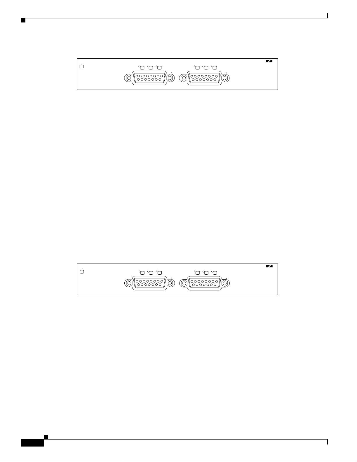
Figure 1-1 PA-2CE1—Faceplate View—PA-2CE1/P RI- 75 Shown
EN
LB
LA
RA
0
LB
LA
CHANNELIZED E1/PRI-75 OHM
RA
1
H8657
OL-3519-01
PA-2CE1 Channelized E1 Port Adapt er In stal lation and Configuratio n
1-1
Page 12
LEDs
Chapter
Figure 1-2 PA-2CE1—Faceplate View—PA-2CE1/P RI- 120 Shown
LEDs
EN
LB
LA
RA
0
LB
LA
CHANNELIZED E1/PRI-120 OHM
RA
1
H9574
When running channelized E1, each 2CE1 interface provides up to 31 E1 channel groups, which are
numbered from 0 to 30. Each channel group provides up to 31, 64 kilobit-per-second (kbps) timeslots
(DS0 channels), which are numbered 1 to 31. Mu ltiple DS0 channels can be mapped to a single channel
group. Each chann el g ro u p is p r esen ted to th e s yst em as a ser ial in t er fac e th at ca n be co nfigured
indi vidu all y. Usable bandwid th for ea ch ch anne l gr oup is calc ula te d as n x 64 kbps, whe re n i s a numb er
of DS0 channels (1 to 31).
When run ni n g IS D N P R I, ea ch 2C E1 i nt er fac e p r ovide s 3 0 be ar er ( B) ch an n els th at can tra nsm it and
receive data at the rate of 64 kbps, full duplex, and one data (D) channel that can transmit and receive
data at the rate of 16 kbps, full duplex. The B channels are used for transmitting user data. The D channel
is used f o r call setu p co nt rol an d network co nn ection te ar d own, an d p rov id es th e commun i cat io n fr o m
the router to the ISDN switch. The B and D channels are presented to the system as serial interfaces that
support High-Level Data Link Control (HDLC) and Point-to-Point protocol (PPP) encapsulation. The
PA-2CE1 support dial-on-demand routing (DDR) when running ISDN PRI.
The PA-2CE 1 h as an enab le d LED , standard o n al l p o rt ad ap te r s, an d six s t atu s LEDs, thr ee f or each
port. (S ee Figu re 1 -3.)
Figure 1-3 LEDs on the PA-2CE1—Horizontal Orientation
EN
LB
LA
RA
0
LB
LA
CHANNELIZED E1/PRI-75 OHM
RA
1
H8657
After sy ste m in it ia lization, th e enabled LED go es on t o i nd i cat e t ha t t he port ada pte r h as b ee n en ab led
for operation.
The following conditions must be met before the
• The PA-2CE1 is cor r ect ly co n ne cte d a nd i s receiving power.
• A valid syst em sof twa re image fo r th e po rt a dapter has b een d ownl oad ed su ccessfully.
• The system recognizes the PA-2CE1 or PA-2CE1-equipped VIP2.
PA-2CE1 i s en ab led:
If any of the above conditions are not met, or if the initialization fails for other reasons, the enabled LED
does not go on .
1-2
PA-2CE1 Channelized E1 Port Adapter Installation and Configuration
OL-3519-01
Page 13

Chapter
Cables, Connectors, and Pinouts
Table 1-1 lists LED colors and indications.
Table 1-1 PA-2CE1 L E D s
LED Label Color State Meaning
ENABLED Gr ee n On This green LE D co m es on w h en th e po rt i s in
loopback mode (line or local). The LED remains
off during normal operation of the port adapter.
LB (loopb ac k) Green On This green LE D co mes on wh en th e incomin g
signal from a remote source has one of the
following alarms: loss of frame (LOF), loss of
signal (L OS), alar m indi catio n sig nal (AI S). The
LED remains off during normal operation of the
port adapter.
LA (local
alarm)
RA (remote
alarm)
Green On This green LE D co mes on w h en th e remote
source’s incoming signal contains a remote alarm
(a yellow a larm). The LED remains off during
normal oper at io n of t h e p ort ad ap ter.
Green On This green LE D co m es on w h en th e po r t i s in
loopback mode (line or local). The LED remains
off during normal operation of the port adapter.
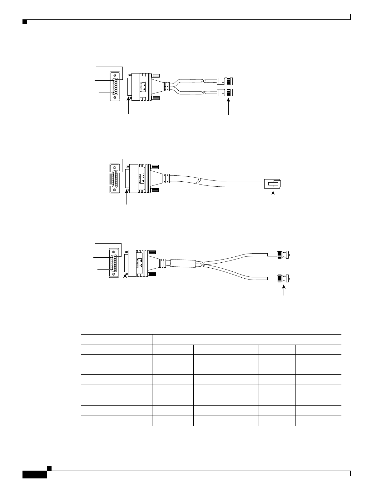
Cables, C onnectors, and Pinouts
Three G.7 0 3 ser ial i nt er face cables are availa bl e f o r use w ith t he PA-2CE1; tw o c ab les for balanced
120-ohm 2CE1 interface connections, and one cable for an unbalanced 75-ohm 2CE1 interface
connecti on .
Note The PA-2CE1 leave the factory configured for balanced 120-ohm or unbalanced 75-ohm
connections. Depending on the circumstances, you might need t o change the configur ation
of both PA-2CE1 interfaces. See the “Setting the PA-2CE1 Jumpers” section on page 3-8
for instructions that explain how to change the configuration of both PA-2CE1 interfaces.
All three cables have a 15-p in, D-shell (DB - 15) connecto r at the rout er (VIP2 or Cisco 7200 series) end
and either twin axial, RJ-45, or BNC connectors at the network end. Figure 1-4, Figure 1-5, and
Figure 1-6 sh ow t h e 2 CE 1 in ter fa ce cab les.
Following are the pr od u ct nu mb er s f or t he 2CE1 in ter fa ce cab les:
• Twin axial cab le—CAB -E 1-T WINA X(= ) or equival ent
• RJ-45 cable —CAB-E1-PRI(=) or equivalent
• BNC ca bl e—CAB-E1-BNC(=) or equivalent
OL-3519-01
PA-2CE1 Channelized E1 Port Adapt er In stal lation and Configuratio n
1-3
Page 14
Cables, Connectors, and Pinouts
Figure 1-4 L2CE1 Twin Axial Cable for Balanced 120-Ohm Connect ions or ISDN PRI Connections
in 1
in 9
in 15
Chapter
DB-15 connector
Twinax connectors
H8667
Figure 1-5 2CE1 RJ-45 Cable for Balanced 120-Ohm or ISDN PRI Connections
Pin 1
Pin 9
Pin 15
DB-15 connector
RJ-45 connector
H8668
Figure 1-6 2CE1 BNC Cable for Unbalanced 75-Ohm Connections or ISDN PRI Connections
Pin 1
Pin 9
Pin 15
DB-15 connector
BNC connectors
H8669
Table 1-2 lists connector pinouts for the 2CE1 interface cables.
1-4
Table 1-2 2CE1 Interface Cabl e Pinouts
2CE1 End Network End
DB-15 Twinax RJ-45 BNC
Pin
1
Signal
2
Pin Signal Pin Signal Signal
9 Tx Tip Tx-1 Tx Tip 1 Tx Tip Tx Tip
2 Tx Ring Tx-2 Tx Ring 2 Tx Ring Tx Shield
10 Tx Shiel d Sh iel d Tx Shield 3 Tx Shiel d –
8 Rx Tip Rx- 1 Rx Ti p 4 Rx Tip Rx Ti p
15 Rx Ring Rx-2 Rx Ring 5 Rx Ring Rx Shield
7 Rx Sh ield Shield Rx Shield 6 Rx Shield –
1. Any pins not d es cr ibe d i n this table a re no t connected .
2. Tx = transmit. Rx = receive.
PA-2CE1 Channelized E1 Port Adapter Installation and Configuration
OL-3519-01
Page 15
Chapter
Port Adapter Slot Locat ions on the Supported Platforms
Port Adapt er Slot Locatio ns on the Supported Platforms
This section discusses port ad apter slot locations o n the supp orted platform s. The illustratio ns that
follow sum mar ize slot lo cation co nvention s o n ea ch platfor m.
Cisco7200 Series Routers S l ot Nu mb eri ng
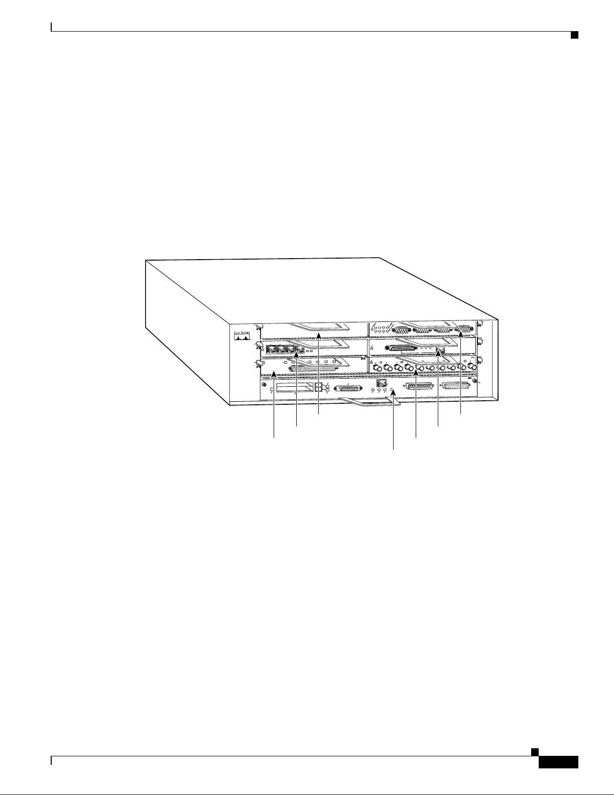
Figure 1-7 shows a Cisco 7206 with port adapters installed. In the Cisco 7206, port adapter slot 1 is in
the lo wer left posit ion, and port adapter slo t 6 is i n the uppe r rig ht positi on. ( The Cisc o 7202, C isco 72 04,
are not shown; however, the PA-2CE1 can be installed in any available port adapter slot.)
Figure 1-7 Port Adapter Slots in the Cisco 72 06
Cisco 7200
Series
5
2
1
0
3
ENABLED
EN
1
1
0
PCMCIA
ENABLED
Port adapter slot 3
Port adapter slot 1
3
LINK
3
1
2
0
3
2
7
6
5
4
SLOT 1
EJECT
SLOT 0
Port adapter slot 5
ETHERNET 10BT
SERIAL-V.35
FE MII
0
ENABLED
EN
RX
MII
RJ-45
EN
EN
TX
RX
TX
1
0
RJ-45
RJ-45
1O PWR
OK
LINK
Port adapter slot 2
Port adapter slot 0
TOKEN RING
3
2
1
FAST ETHERNET
RJ45
LINK
MII
0
RX
2
FAST ETHERNET INPUT/OUTPUT CONTROLLER
ETHERNET-10BFL
RX
TX
RX
TX
4
3
Port adapter slot 6
Port adapter slot 4
6
4
TX
2
0
28329
OL-3519-01
PA-2CE1 Channelized E1 Port Adapt er In stal lation and Configuratio n
1-5
Page 16

Port Adapter Slot Locations on the Supported Pl atforms
VIP2 Sl ot Numbering
Figure 1-8 shows a pa rtial view of a VIP mothe rboar d with inst alle d port adapters. W it h the mothe rboard
oriented as shown in F igure 1-8, the left port adapter is in port adapter slot 0, and the right port adapter
is in por t ada pt er s l ot 1. The p o rt ad ap t er slo ts ar e alw ay s n u m be red 0 an d 1 .
Figure 1-8 VIP Motherboar d with Two Port Adapters Installed—Horizontal Orientation
Chapter
Port adapter slot 0
Port adapter slot 1
Port adapter
handles not
shown
Note In the Cisco 7000, Cisco 7507, and Cisco 7513 chassis, the VIP motherboard is installed
vertically. In the Cisco 7010 and Cisco 7505 chassis, the VIP motherboard is installed
horizontally.
Interface p roc e ss or s l ots ar e nu mb er ed a s sh own in F i gu re 1- 9.
Figure 1-9 Interface Slot N umbe rs— Cisco 7505 Shown
VIP in interface processor slot 3
ROUTE SWITCH PROCESSOR
CONSOLE
Slot 3
Slot 2
Slot 1
Slot 0
Interface
processor
slots
NORMAL
EJECT
SLOT 1
SLOT 0
CPU HALT
RESET
29328
1-6
29619
PA-2CE1 Channelized E1 Port Adapter Installation and Configuration
OL-3519-01
Page 17

Chapter
Identifying Interface Addresses
This section describes how to identify interface addresses for the PA-2CE1 in supported platforms.
Interface ad d re s ses sp ec if y th e actual p hy sical locat io n of e ach i nt er fac e o n a r o ut er o r s wi tc h.
Interfaces o n th e PA-2CE1 in s tal led i n a r o ut er m ai n tai n th e s a m e a dd r ess re ga rdless of wh et he r ot he r
port ada pte rs ar e in stalled or re mov ed. H owever, when y o u move a p or t ad ap ter t o a d iffer en t slot, the
first numb er in t he in terface ad dress chan ge s to r ef le c t th e n ew po rt ad ap t e r s lo t nu mb er.
Interfaces on a PA-2CE1 installed in a VIP2 maintain the same address regardless of whether other
interface pr o cesso r s are insta lle d or re mov ed . H owever, when y o u m ove a V I P 2 t o a d iffer en t sl o t, t h e
interface pr o ces so r s l ot n um b er c ha ng es to r ef lect the n ew in terface p ro ce s sor slot.
Note Interface ports are numbered from left to right starting with 0.
Table 1-3 explains how to identify interface addresses.
Table 1-3 Identifying Interface Addresses
Identifying Inter fa ce Addr esses
Platform Interface Address Format Numbers Syntax
Cisco 7200 series routers Port-adapter-slot-number/interface-port-number Port adapter slot—0 through
VIP2 in Cis co 7000 series or
Cisco 7500 series routers
1. Port adapter slot 0 is reserved for the Fast Ethernet port on the I/O controller (if present).
Interface-processor-slot-number/port-adapter-slotnumber/interface-port-number
6 (depends on the number of
slots in the router)
Inte rf a ce por t —0 or 1
Interface processor slot—0
through 12 (depends on the
number of slots in the
router)
Port adapter sl ot—0 or 1
Inte rf a ce por t —0 or 1
1
1/0
3/1/0
Cisco7200 Series Routers I n t erf ac e Addresses
This section describes how to identify the interface addresses used for the PA-2CE1 in Cisco 7200 series
routers. The interface address is composed of a two-part number in the format
port-adapter-slot-number/interface-port-number. See Table 1-3 for the interface address format.
In Cisco 7200 series routers, port adapter slots are numbered from the lower left to the upper right,
beginning with port adapter slot 1 and continuing through port adapter slot 2 for the Cisco 7202, slot 4
for the Cisco 7204, and slot 6 for the Cisco 7206. (Port adapter slot 0 is reserved for the optional Fast
Ethernet port on the I/O controller—if p re sen t.)
The interfac e addresses of the in terfaces o n t he PA-2CE1 in port adapter slot 1 are
1/0 thr ough 1/7 ( port a dapte r slot 1 and int erfa ces 0 through 7). I f the PA-2CE1 was in port ada pter s lot 4,
these same interfaces would be numbered 4/0 through 4/7 (port adapter slot 4 and interfaces
0 through 7).
OL-3519-01
The interface addresses of the interfaces on a P A- 2CE1 i n port ad apter sl ot 2 are 2/0 and 2/1 (p ort adapter
slot 2 and interfaces 0 and 1). If the PA-2CE1 was in port adapter slot 1, these same interfaces would be
numbered 1/0 and 1/1 (port adapter slot 1 and interfaces 0 and 1).
PA-2CE1 Channelized E1 Port Adapt er In stal lation and Configuratio n
1-7
Page 18

Identifyin g In te rfa ce A ddre sse s
VIP2 Inte rf ace Addresses
This section describes how to identify the interface addresses used for the PA-2CE1 on a VIP2 in
Cisco 7000 series and Cisco 7500 series routers.
Note Although the processor slots in the 7-slot Cisco 7000 and Cisco 7507 and the 13-slot
Cisco 7513 and Cisco 7576 are vertically oriented and those in the 5-slot Cisco 7010 and
Cisco 7505 are horizontally oriented, all Cisco 7000 series and Cisco 7500 series routers
use the same method for slot and port numbering.
See Table 1-3 for the interface address format. The interface address is composed of a three-part number
in the fo r mat inte rface-processor-slot-number/port-adapter-slot-number/interface-port-number.
If the VIP2 is inserted in interface processor slot 3, then the interface addresses of the PA-2CE1 are 3/1/0
through 3/1/7 (interface processor slot 3, port adapter slot 1, and interfaces 0 through 7). If the
port adapter was in port adapter slot 0 on the VIP2, these same interface addresses would be numbered
3/0/0 th r ough 3/0/7.
Chapter
Note If you remove the VIP2 with the PA-2CE1 (shown in Figure 1-9) from interface processor
slot 3 and i nstall it i n in ter fa ce pr o cesso r s lo t 2, th e i n ter fa ce a dd r esse s be co m e 2/ 1/ 0
through 2/1/7.
1-8
PA-2CE1 Channelized E1 Port Adapter Installation and Configuration
OL-3519-01
Page 19

Preparing for Installation
This chapter describes the general equipment, safety, and site preparation requirements for installing the
PA-2CE1. Th i s ch ap te r c on t ain s the follow in g s ect io ns :
• Required Tools and Equipment, page 2-1
• Software and Hardware Requirements, page 2-2
• Checking Hardwa re and S of t wa r e Comp a t ib ility, page 2-2
• Safety G u id el in es , page 2-3
• FCC Class A Compliance, page 2-7
Required Tools and Equipment
You need the follo wing to ols and part s to insta ll a port a dapter. If you need additio nal equi pment , contact
a servic e r ep r esen ta tive f o r o r de r ing i n fo r mat ion.
CHAPTER
2
• PA-2CE1/PRI-75(=) or PA-2CE1/PRI-120(=).
• VIP2 (for i ns tal lat io n in Ci sco 7000 seri es or Cis co 7500 serie s c has sis on ly ). F or in for mat io n abo ut
the spe cifi c VIP2 mode ls that support the PA-2CE1, see the “Software an d Hardwar e Requirement s”
section on page 2-2.
• E1 interface cables. (See the “Cables, Connectors, and Pinouts” section on page 1-3.
• Number 1 Phillips and a 3/16-inch flat-blade screwdriver (for VIP2 installation only).
• Your own electrostatic discharge (ESD)-prevention equipment or the disposable grounding wrist
strap included with all upgrade kits, field-replaceable units (FRUs), and spares.
• Antistatic mat.
• Antistatic container.
OL-3519-01
PA-2CE1 Channelized E1 Port Adapt er In stal lation and Configuratio n
2-1
Page 20

Chapter
Software and Hardware Requirements
Software and Hardware Requi remen ts
Table 2-1 lists the recommended minimum Cisco IOS software release required to use the PA-2CE1in
supported router or switch platforms.
Table 2-1 PA-2CE1 Software Requirements
Platform Recommended Minimum Cisco IOS Release
Cisco 7200 series
• Cisco 7204 and Cisco 7206
• Cisco 7202 Cisco IOS Release 11.1(19)CC1 or a later release of Cisco IOS Release 11.1 CC
VIP2 in the Cisco 7000 series and
Cisco 7500 series
• With VIP2 -4 0 (=)
• With VIP2 -50 (= ) Cisco IOS R el eas e 11 .1 ( 14) CA or a lat er r el eas e of C isc o IOS Release 11.1 CA
1. Cisco 7200 series routers require a minimum of 32 MB of DRAM to support up to five installed PA-2CE1s that are running ISDN PRI or channelized
E1.
2. The PA-2CE1 can be used in the VIP2 in all Cisco 7500 series routers using a Route Switch Processor (RSP), and in Cisco 7000 series routers using
the RSP7000 and RSP7000CI.
3. The specific VIP2 models recommended for the PA-2CE1s are VIP2-40(=), which has 2 MB of SRAM and 32 MB of DRAM, and VIP2-50(=), which
has 4 to 8 MB of SR AM and 32 to 128 MB of SDRAM . Th e VIP2 -4 0 and VIP2- 50 s upp or t two i nsta ll ed PA-2C E1s that are r unn in g IS DN PR I with
distributed services or channelized E1 with distributed switching or distributed services. The VIP2-20=, which has 1 MB of SRAM and 16 MB of
DRAM, supports two installed PA-2CE1 that are running ISDN PRI or channelized E1 with distributed switching. The VIP2-15(=), which has 1 MB
of SRAM and 8 MB of DRAM, supports one installed PA-2CE1 that is running ISDN PRI or channelized E1 without distributed switching.
4. Cisco 7000, Cisco 7500, and Cisco 7200 series routers support up to five installed PA-2CE1 that are running ISDN PRI (ten E1 ports total, including
E1 ports on MultiChannel Interface Processors installed in Cisco 7000 series or Cisco 7500 series routers). There are no such limitations when
installe d PA - 2CE 1s ar e ru nnin g ch an nel ized E1.
1
Cisco IOS R el ease 11.1(9) C A 1 or a lat e r r el eas e of Cisco IOS R elease 11. 1 CA
Cisco IOS R el eas e 12 .2 ( 4)B o r a l ater relea se o f Ci s co I O S Release 12 .2 B
Cisco IOS R el eas e 11 .3 (4) A A o r a l ate r re lea s e o f Cisco IOS R ele as e 11 .3 A A
Cisco IOS R el eas e 12 .2 ( 4)B o r a l ater relea se o f Ci s co I O S Release 12 .2 B
2 3 4
Cisco IOS Release 11.1(7)CA or a later release of Cisco IOS Release 11.1 CA
For configuration guidelines on port adapters in the Cisco 7200 series, refer to the Cisco 72 00 Se ri es
Port Adapter Hardware Configuration Guidelines.
Checking Har dwa re and Software Compatibility
To check the minimum software requirements of Cisco IOS software with the hardware installed on your
router, Cisco maintains the Software Advisor tool on Cisco.com. This tool does not verify whether
modules w it hi n a sy s te m ar e compati bl e, but it d oes prov id e t h e m i ni mu m I O S r eq ui re m en ts fo r
individual hardware modules or components.
Note Access to this tool is limited to users with Cisco.com login accounts.
T o access Software Advisor, click Login at Cisco.com and go to Tec hnical Support Help—Cisc o TAC:
Tool Index: Software Advisor. You can also access the tool by pointing your browser directly to
http:/ /w w w.cisco.com/cg i- bin/su p po r t/Comp Nav /I nd ex.pl.
Choose a product family or enter a specific product number to search for the minimum supported
software release needed for your hardware.
PA-2CE1 Channelized E1 Port Adapter Installation and Configuration
2-2
OL-3519-01
Page 21

Chapter
Safety G u idelines
This se cti on provi d es s a fe ty guidelin es that you s h ou ld f o llow when wo r ki ng w ith any equipment that
connects to electrical power or telephone wiring.
Safety Warnings
Safety warnings appear throughout this publication in procedures that, if performed incorrectly, might
harm you . A war n in g sym bo l pr ec ed es ea ch wa r ni ng s t ate m en t.
Safety Gu idelin e s
Warning
Waarschuwing
Varoitus
Attention
This warning symbol means danger. You are in a situation that could cause bodily inj ury. Before you
work on any equipment, be aware of the hazards involved with electrical circui try and be familiar
with standard practices for preventing accidents. To see translations of the warnings that appear in
this publication, refer to the Regulatory Compliance and Safety Information document that
accompanied this device.
Dit waarschuwingssymbool betekent gevaar. U verkeert in een situatie die lichamelijk letsel kan
veroorzaken. Voordat u aan enige apparatuur gaat werken, dient u zich bewust te zijn van de bij
elektrische schakelingen betrokken risico's en dient u op de hoogte te zijn van standaard
maatregelen om ongelukken te voorkomen. Voor vertalingen van de waarschuwingen die in deze
publicatie verschijnen, kunt u het document Regulatory Compliance and Safety Information
(Informatie over naleving van veiligheids- en andere voorschriften) raadplegen dat bij dit toestel is
ingesloten.
Tämä varoitusmerkki merkitsee vaaraa. Olet tilanteessa, joka voi johtaa ruumiinvammaan. Ennen
kuin työskentelet minkään laitteiston parissa, ota selvää sähkökytkentöihin liittyvistä vaaroista ja
tavanomaisista onnettomuuksien ehkäisykeinoista. Tässä julkaisussa esiintyvien varoitusten
käännökset löydät laitteen mukana olevasta Regulatory Compliance and Safety Information
-kirjasesta (määräysten noudattaminen ja tietoa turvallisuudesta).
Ce symbole d'avertissement indique un danger. Vous vous trouvez dans une situation pouvant caus er
des blessures ou des dommages corporels. Avant de travailler sur un équipement, soyez conscient
des dangers posés par les ci rcuits él ectriques e t f amiliarisez -vous av ec le s procédures couramm ent
utilisées pour éviter les accidents. Pour prendre connaissance des traductions d’avertissements
figurant dans cette publication, consultez le document Regulatory Compliance and Safety
Information (Conformité aux règlements et consignes de sécurité) qui accompagne cet appareil.
OL-3519-01
Warnung
Dieses Warnsymbol bedeutet Gefahr. Sie befinden sich in einer Situation, die zu einer
Körperverletzung führen könnte. Bevor Sie mit der Arbeit an irgendeinem Gerät beginnen, seien Sie
sich der mit elektrischen Stromkreisen verbundenen Gefahren und der Standardpraktiken zur
Vermeidung von Unfällen bewußt. Übersetzungen der in dieser Veröffentlichung enthaltenen
Warnhinweise finden Sie im Dokument Regulatory Compliance and Safety Information
(Informationen zu behördlichen Vorschriften und Sicherheit), das zusammen mit diesem Gerät
geliefert wurde.
PA-2CE1 Channelized E1 Port Adapt er In stal lation and Configuratio n
2-3
Page 22

Safety Guidelines
Chapter
Avvertenza
Advarsel
Aviso
¡Advertencia!
Questo simbolo di avvertenza indica un pericolo. La situazione potrebbe causare infortuni alle
persone. Prima di lavorare su qualsiasi apparecchiatura, occorre conoscere i pericoli relati vi ai
circuiti elettrici ed essere al corrente delle pratiche standard per la prevenzione di inci denti. L a
traduzione delle avvertenze riportate in questa pubblicazione si trova nel documento Regulatory
Compliance and Safety Information (Conformità alle norme e informazioni sulla sicurezza) che
accompagna questo dispositivo.
Dette varselsymbolet betyr fare. Du befinner deg i en situasjon som kan føre til personskade. Før du
utfører arbeid på utstyr, må du vare oppmerksom på de faremomentene som elektriske kretser
innebærer, samt gjøre deg kjent med vanlig praksis når det gjelder å unngå ul ykker. Hvis du vil se
oversettelser av de advarslene som finnes i denne pu blikasjonen, kan du se i dokumentet Regulatory
Compliance and Safety Information (Overholdelse av forskrifter og sikkerhetsinformasjon) som ble
levert med denne enheten.
Este símbolo de aviso indica perigo. Encontra-se numa situação que lhe poderá causar danos
físicos. Antes de começar a trabalhar com qualquer equipamento, familiarize-se com os perigos
relacionados com circuitos eléctricos, e com quaisquer práticas comuns que possam prevenir
possíveis acidentes. Para ver as traduções dos avisos que constam desta publicação, consulte o
documento Regulatory Compliance and Safety Information ( Informação de Segurança e Disposições
Reguladoras) que acompanha este dispositivo.
Este símbolo de aviso significa peligro. Existe riesgo para su integridad física. Antes de manipular
cualquier equipo, considerar los riesgos que entraña la corriente eléctrica y familiarizarse con los
procedimientos estándar de prevención de accidentes. Para ver una traducción de las advertencias
que aparecen en esta publicación, consultar el documento titulado Regulatory Compliance and
Safety Information (Información sobre seguridad y conformidad con las disposiciones
reglamentarias) que se acompaña con este dispositivo.
Varning!
Denna varningssymbol signalerar fara. Du befinner dig i en situation som kan l eda till personskada.
Innan du utför arbete på någon utrustning måste du vara medveten om farorna med elkretsar och
känna till vanligt förfarande för att f örebygga skador. Se förklaringar av de varningar som förkommer
i denna publikation i dokumentet Regulatory Compliance and Safety Information (Efterrättelse av
föreskrifter och säkerhetsinformation), vilket medföljer denna anordning.
Electric al Equipment Guidelines
Follow these basic guidelines when working with any electrical equipment:
• Before b egi nnin g any p r oc ed ur es requirin g access to th e cha s sis in ter io r, locat e the em ergency
power-off switch for the room in which you are working.
• Disconne ct all p owe r an d external cab l es b ef ore moving a c ha s sis; do n o t w ork al on e wh en
potentially hazardous conditions exist.
• Never assum e t hat p owe r ha s be en d isco n nected fro m a circuit; alw ays ch eck .
• Do not perform any action that creates a potential hazard to people or makes the equipment unsafe;
carefully examine your work area for possible hazards such as moist floors, ungrounded power
extension cables, and missing safety grounds.
2-4
PA-2CE1 Channelized E1 Port Adapter Installation and Configuration
OL-3519-01
Page 23

Chapter
Telephone Wiring Guidel i nes
Use the f ollowing guidelines wh en wor king wi th any eq ui pment t ha t is conne cte d t o tel epho ne wiring or
to other network cabling:
• Never install telephone wiring during a lightning storm.
• Never instal l teleph o ne ja cks in wet locations unl e ss t h e j ack is specifi cal ly d e si gn ed for wet
location s .
• Never touch uninsulated telephone wires or terminals unless the telephone line has been
disconnected at the network interface.
• Use caution when installing or modifying telephone lines.
Safety Gu idelin e s
OL-3519-01
PA-2CE1 Channelized E1 Port Adapt er In stal lation and Configuratio n
2-5
Page 24

Safety Guidelines
Preventi ng Electrostat i c Discharge Damage
Electrostatic discharge (ESD) damage, which can occur when electronic cards or components are
improper l y h an d led , re s ults i n co mplete or in te rmittent f ai lu re s. P o rt ad ap te r s an d pro ces so r m o d ul es
comprise printed circuit boards that are fixed in metal carriers. Electromagnetic interference (EMI)
shielding and connectors are integral components of the carrier. Although the metal carrier helps to
prote ct the b oa rd from ESD , us e a preven tive antistatic s t r a p du ring handli ng .
Following are gu id el in es f o r pr eventin g ES D d amage:
• Always use an ESD w r ist o r an kl e st ra p an d e nsu re t ha t i t m ake s g oo d ski n co ntact .
• Connect the equipment end of the strap to an unfinished chassis surface.
• When in sta lling a co mp o nen t , u s e a ny availab le eje ctor levers or cap tive i n s tal lat io n scr ews t o
properly seat t he bus connect o rs i n th e b ackplane o r mid p lan e. Th ese devices prevent acc id en tal
removal, provid e proper gr o un din g f o r th e sy s t em, and hel p to en su re th at bu s co nnectors ar e
properly seat ed .
• When re mov in g a c omp o ne nt , u s e any available ejector l evers o r captive insta llation scr ews to
release t h e bus co nnectors f rom t he b ack p lan e or m i dp l an e.
• Handle carriers by available handles or edges only; avoid touching the printed circuit boards or
connecto rs .
Chapter
• Place a removed board component-side-up on an antistatic surface or in a static shielding container.
If you pl an to r et ur n th e co m pon en t t o th e f act or y, imme diately plac e i t i n a s t ati c s h i eld in g
container.
• Avoid contact between the printed circuit boards and clothing. The wrist strap only protects
componen ts from ESD volt ag es o n th e body; ES D voltages on clo t hi ng c an s ti ll cau se damage.
• Never atte mp t t o remove t h e p ri n ted ci r cu it board f rom t he metal ca rr ie r.
Caution For safety, periodically check the resistance value of the antistatic strap. The measurement
should be between 1 and 10 megohms (Mohm).
2-6
PA-2CE1 Channelized E1 Port Adapter Installation and Configuration
OL-3519-01
Page 25

Chapter
FCC Class A Compliance
This equi pment ha s been tested a nd foun d to comp ly with th e limi ts for a Cl ass A digital devi ce, pursu ant
to part 15 of the FCC rules. These limits are designed to provide reasonable protection against harmful
interferen ce when th e e qu ip ment is oper at ed in a commer c ial enviro nment. Thi s eq u ip men t ge nerates,
uses, and can radiate radio-frequency energy and, if not installed and used in accordance with the
instructi on manual, may ca use harmfu l in terference to rad io co mmunications. Op er at io n o f t h is
equipm en t i n a resi de nt ial area is li kely to cau se ha rmful in ter f er en ce, in wh ich case us e rs will b e
required to correct the interference at their own expense.
Yo u c an determine w het h er yo ur equipmen t i s cau si ng in terference by t ur n in g i t off. If th e in t e rfe re nc e
stops, it was probably caused by the Cisco equipment or one of its peripheral devices. If the equipment
causes interference to radio or television reception, try to correct the interference by using one or more
of the f ollowing mea sur e s:
• Turn the television or radio antenna until the interference stops.
• Move the equipment to one side or the other of the television or radio.
• Move the equipment farther away from the television or radio.
• Plug the equipment into an outlet that is on a different circuit from the television or radio. (That is,
make certain the equipment and the television or radio are on circuits controlled by different circuit
breakers or fuses.)
FCC Class A Compliance
Note The PA-2CE1 has b een designed to m eet these requirements. Modifications to this prod uct
that are not authorized by Cisco Systems, Inc. could void the various approvals and negate
your authority to operate the product.
OL-3519-01
PA-2CE1 Channelized E1 Port Adapt er In stal lation and Configuratio n
2-7
Page 26

FCC Class A Complia nce
Chapter
2-8
PA-2CE1 Channelized E1 Port Adapter Installation and Configuration
OL-3519-01
Page 27

CHAPTER
3
Removing and Installing Port Adapters
This chapt er de scr ibes ho w to re mov e th e PA-2CE1 port adap ter fr om suppo rted platf orm s and al so ho w
to inst all a new or r ep lacemen t p ort ad ap ter. This chapte r co nt ain s t he f ol lowin g s ect io ns :
• Handling Port Adapters, page 3-2
• Online Insertion and Removal, page 3-2
• Warnings and Cautions, page 3-3
• Port Adapt er Removal a n d Installation , page 3- 4
• Connecting a PA-2CE1 Interface Cable, page 3-7
• Settin g th e PA-2CE1 Jum pe rs , page 3 -8
Each por t a da pt er ci rc ui t b o ar d is mounted t o a m e tal carrier an d is sensitive to e lec tr o stat ic discharg e
(ESD ) da mag e.
Note When a port adapte r slo t is not in use , a blan k port ada pte r must f il l th e empty slo t to allo w
the router or switch to conform to electromagnetic interference (EMI) emissions
requirements and to allow proper airflow across the port adapters. If you plan to install a
new port adapter in a slot that is not in use, you must first remove the blank port adapter.
Caution When powering off the router, wait a minimum of 30 seconds before powering it on again.
OL-3519-01
PA-2CE1 Channelized E1 Port Adapt er In stal lation and Configuratio n
3-1
Page 28

Handling Port Adapters
Handling Port Adapters
Caution Always handle the port adapter by the carrier edges and handle; never touch the
port adapter components or connector pins. (See Figure 3-1.)
Figure 3-1 Handling a Port Adapter
Metal carrier
Printed circuit board
Chapter
H6420
Online Insertion and Removal
Several platforms support online insertion and removal (OIR) of port adapters; therefore, you do not
have to power d own r outer s when r e moving and re pl a cing a PA-2CE1 in Cis c o 7200 s er ie s ro uters.
Althoug h th e V IP2 s u ppo rt s o nl ine in ser tio n an d removal, in d ividual port adap t er s do n o t. To replace
port adapt er s, y ou mu s t first r em ove the VI P2 from th e ch assis and then in s tal l o r rep la ce p or t ad ap ter s
as required. If a blank port adapter is installed on the VIP2 on which you want to install a new
port adapter, you must first remove the VIP2 from the chassis and then remove the blank port adapter.
Caution To prevent system problems, do not remove port adapters from the VIP2 motherboard or
attempt to install other por t adapters on the motherboard when the system is operating. To
install or replace port adapters, first remove the VIP2 from its interface processor slot.
It is wise to gracefully shut down the system before removing a port adapter that has active traffic moving
through it. Removing a module while traffic is flowing through the ports can cause system disruption.
Once the module is inserted, the ports can be brought back up.
Note As you disengage the module from the router or switch, online insertion and removal (OIR)
administ r atively shuts d ow n a ll active inte rfaces in t he m o du le.
OIR allows you to install and replace modules while the router is operating; you do not need to notify
the soft ware or sh ut d own t he syst em po w er , alt hou gh you s houl d not run traf fic through the modul e you
are removi ng w h il e i t i s b ein g r emove d. O IR i s a metho d th at is se am l es s t o en d u s ers o n th e ne tw or k ,
maintains all routing information, and preserves sessions.
3-2
The following is a functional description of OIR for background information only; for specific
procedures for installing and replacing a module in a supported platform, refer to the “Port Adapter
Removal and In sta llati on” section on page 3-4.
PA-2CE1 Channelized E1 Port Adapter Installation and Configuration
OL-3519-01
Page 29

Chapter
Warnings and Cautions
Each modul e ha s a bus conn ect or th at co n ne cts it to the rout er. The conne cto r has a s et of tier e d pin s in
three lengths that send specific signals to the system as they make contact with the module. The system
assesse s the signals it rece ives and the order in which it receives them to determine if a module is being
removed from or in trod u ced t o t h e s y ste m . Fr o m th es e s i gn al s, th e system de ter m i ne s w h eth er t o
reinitial iz e a new in te rface or to shu t down a disconn ect ed in terface.
Specifically, when you insert a module, the longest pins make contact with the module first, and the
shortest pins make contact last. The system recognizes the signals and the sequence in which it receives
them.
When you remove or insert a module, the pins send signals to notify the system of changes. The router
then perfoms the following procedure:
1. Rapidly scan s t he s y stem for c onfig urat io n ch an ge s .
2. Initializes n ewl y in ser ted p o rt ad ap te rs or admi n istr at ively sh ut s d own any vaca nt i nt er fac es.
3. Brings all p r evio usly confi gu r ed in terfaces o n the modul e b ac k to thei r pr evio u s ly in stalled s ta te.
Any newly in s er te d i nt er face is put in th e administratively sh u td own s ta te, as i f it wa s pr esent (but
not configured) at bo ot tim e. I f a s imila r modu le ty pe is r eins ert ed int o a s lot , its po rt s a re c on f igur ed
and brought online up to the port count of the originally installed module of that type.
Note Before you beg in insta llati on, rea d Chapte r 2, “Preparin g for Inst allat ion,” for a li st of part s
and tools req uir ed for inst allati on.
Warnings and Cautions
Observe the following warnings and cautions when installing or removing port adapters.
Caution Do no t s lid e a p or t ad ap ter all th e way int o th e s l ot until yo u h ave connected all required
cables. Trying to do so disrupts normal operation of the router or switch.
Note If a port a da pt er lever o r oth er r etaining m ech an is m do e s no t m ove to th e lo cked position,
the port ad ap te r is n o t c ompletely seated i n th e midplan e. C a re fully pu ll th e p o rt ad ap t e r
halfwa y out of the slo t, re ins ert i t, and m ove the port ad ap ter lever or othe r mec ha nis m to
the locked p osition .
Caution To prevent jamming t h e ca rrier betw een th e u p pe r and t he lowe r ed ges of the p o rt ad apter
slot, and to en s u re th at th e edge conn ec to r at th e r ear of the p or t ad apt er m a tes with t he
connecti on at th e re ar o f th e p o rt ad ap te r s lo t, make certain t ha t t he carrier is p o sitioned
correctl y, as show n in th e cutaway in the f o ll owi ng i llu s tr at io n s .
OL-3519-01
Warning
When performing the following procedures, wear a grounding wrist strap to avoid ESD
damage to the card. Some platforms have an ESD connector for attaching the wrist strap.
Do not directly touch the midplane or backplane w ith your hand or any metal tool, or you
could shock yourself.
PA-2CE1 Channelized E1 Port Adapt er In stal lation and Configuratio n
3-3
Page 30

Port Adapter Re mov a l and Ins ta lla tio n
Port Adapter Removal and Installation
In this section, the illustrations that follow give step-by-step instructions on how to remove and install
port adapters. This section contains the following illustrations:
• Cisco 7200 Series—Removing and Installing a Port Adapter, page 3-5
• VIP2—Rem oving a nd I n s ta l li ng a Port Adapter, page 3-6
Chapter
3-4
PA-2CE1 Channelized E1 Port Adapter Installation and Configuration
OL-3519-01
Page 31

Chapter
Port Ada p te r Re mo v a l a n d In stallat io n
Cisco 7200 S eries —Removing and Installing a Port Adapter
Step 1
To remove the port adapter, place
the port adapter lever in the
unlocked position. (See A.) The
port adapter lever remains in the
unlocked position.
Step 2
Grasp the handle of the port adapter
and pull the port adapter from the
router, about halfway out of its slot.
If you are removing a blank port
adapter, pull the blank port adapter
completely out of the chassis slot.
Step 3
With the port adapter halfway out of
the slot, disconnect all cables from
the port adapter. After disconnecting
the cables, pull the port adapter
from its chassis slot.
Step 4
To insert the port adapter, carefully
align the port adapter carrier
between the upper and the lower
edges of the port adapter slot.
(See B.)
Step 5
Carefully slide the new port adapter
halfway into the port adapter slot.
(See B.)
Step 6
With the port adapter halfway into
the slot, connect all required cables
to the port adapter. After connecting
all required cables, carefully slide
the port adapter all the way into the
slot until the port adapter is seated
in the router midplane.
A
Note: This adapter
removal applies to any
port or service adapter.
Slot
guide
B
Cisco 7200
Series
Cisco 7200
Series
Port adapter lever
(locked position)
5
3
2
1
0
3
ENABLED
EN
TD
1
1
0
LB
RC
RD
TC
TD
CD
LB
RC
RD
TC
ENABLED
PCMCIA
ETHERNET 10BT
LINK
3
2
FAST SERIAL
LB
RC
RD
TC
TD
CD
LB
RC
RD
TC
TD
CD
SLOT 1
FE MII
EJECT
SLOT 0
0
ENABLED
CD
CPU RESET
RJ-45
MII
RJ45
RJ45
EN
OK
EN
1O PWR
LINK
RJ45
LINK
MII
0
FAST ETHERNET INPUT/OUTPUT CONTROLLER
FAST ETHERNET
4
2
0
TOKEN RING
6
3
2
1
Port adapter lever
(unlocked position)
TOKEN RING
6
3
2
1
5
3
2
1
0
LINK
3
ENABLED
1
1
0
ENABLED
PCMCIA
ETHERNET 10BT
3
2
FE MII
SLOT 1
EJECT
SLOT 0
0
ENABLED
CPU RESET
RJ-45
MII
RJ45
RJ45
EN
OK
EN
1O PWR
LINK
RJ45
LINK
MII
0
FAST ETHERNET INPUT/OUTPUT CONTROLLER
FAST ETHERNET
4
2
27996
Step 7
After the port adapter is properly
seated, lock the port adapter lever.
(See A.)
Cisco uBR7 200 Series—Removing a Port Adapt er
PA-2CE1 Channelized E1 Port Adapt er In stal lation and Configuratio n
OL-3519-01
3-5
Page 32

Port Adapter Re mov a l and Ins ta lla tio n
VIP2—Removing and Installing a Port Adapter
Note: You must first remove the VIP
from the chassis before removing a port
adapter from the VIP.
Step 1
To remove the port adapter, remove
the screw that secures the port
adapter (or blank port adapter).
(See A.)
Step 2
With the screw removed, grasp the
handle on the front of the port adapter
(or blank port adapter) and carefully pull
it out of its slot, away from the edge
connector at the rear of the slot. (See A.)
Step 3
To insert the port adapter, carefully align
the port adapter carrier between the
upper and the lower edges of the port
adapter slot. (See B.)
Step 4
Carefully slide the new port adapter into
the port adapter slot until the connector
on the port adapter is completely seated
in the connector at the rear of the port
adapter slot. (See B.)
A
Screw
B
Chapter
Carrier
Upper edge
Lower edge
Step 5
Install the screw in the rear of the port
adapter slot on the VIP. Do not
overtighten the screw. (See A.)
Step 6
Carefully slide the VIP motherboard into
the interface processor slot until the
connectors at the rear of the VIP are
completely seated in the connectors at
the rear of the interface processor slot.
Use the ejector levers to seat the VIP in
the interface processor slot. Tighten the
captive installation screws on the VIP.
(See C.)
Captive
installation
screw
C
EJECT
SLOT 1
NORMAL
SLOT 0
CPU HALT
RESET
AUX.
ROUTE SWITCH PROCESSOR
CONSOLE
26520
3-6
PA-2CE1 Channelized E1 Port Adapter Installation and Configuration
OL-3519-01
Page 33

Chapter
Connecting a PA-2CE1 Interface Cable
On a single PA-2CE1, you can use up to two G.703 serial connections.
Use the following procedure to connect a PA-2CE1 interface cable:
Step 1 Attach th e cable dir ect ly t o t he r ece pt acl e o n th e PA-2CE1 and tigh te n t h e s t ra in -rel ief s c rew s. ( See
Figure 3-2.)
Note Port adapte rs h ave a hand le attached, but th is han d le is no t shown to al low a detai le d vi ew
of each p ort ad ap te r face pl at e.
Figure 3-2 Connecting a PA-2CE1 Int erface Cable (Front View—Sho w n without Handle)
Connecting a PA-2CE1 Interface Cable
EN
LB
LA
RA
0
LB
LA
RA
1
H8663
Strain-relief screw
OL-3519-01
To PRI CSU
Step 2
Attach the network end of the cable to your Primary Rate Interface (PRI) channel service unit (CSU) and
tighte n the stra in-r elie f screws .
Step 3 Repeat Step 1 and Ste p 2 for ad d itional ca bl es y ou want to in st all.
This com pl etes the pr o ced u re f or attachin g a PA-2CE1 int er fac e c a b le.
PA-2CE1 Channelized E1 Port Adapt er In stal lation and Configuratio n
3-7
Page 34

Setti n g t h e PA-2CE 1 Jumper s
Setting the PA-2CE1 Jumpers
Depending on the circumstances, you might need to change the configuration of both PA-2CE1
interfaces for balanced 120-ohm connections or unbalanced 75-ohm connections.
Configuring PA-2CE1 interfaces for balanced 120-ohm or unbalanced 75-ohm connections requires
setting ten jumpers on the 2CE1 printed circuit board and attaching the appropriate interface cable
(balanced or unbalanced) to both 2CE1 ports. See the “Cables, Connectors, and Pinouts” sect ion on
page 1-3 for 2CE1 interface cable types. The following steps explain how to set 2CE1 jumpers for
balanced 120-ohm or unbalanced 75-ohm connections.
Note Both 2CE1 ports must be configured for balanced 120-ohm or unbalanced 75-ohm
connections. The PA-2CE1 does not support a mixed connection configuration.
Step 1 Attach an ESD-preventive w r ist s trap b etween y ou and an u n finis h ed ch ass i s s u rface.
Step 2 Remove the VIP2 from the chassis. To do so, follow the steps in the section “Removin g a VIP2 ” in the
configuration note Second-Gen erati on Versatile Interface Processo r ( VI P 2 ) In stallati on a nd
Configuration, which shipped with your VIP2.
Chapter
Step 3 Remove the installed PA-2CE1 from the VIP2. See the “VIP2—Removing and Installing a Port Adapter”
section on page 3-6 for port adapter removal procedures.
Step 4 With the PA-2CE1 on an antis tatic mat, us e a n umber 1 Phillip s screwdriver t o r emove the thr ee screws
that secure the plastic jumper c over t o the 2C E1 printed circuit board. (See Figure 3-3.) Save the screws.
Figure 3-3 Removi ng the Jum per Cover (Bottom View of the PA-2CE1)
Port 0 Port 1
J2 J8
J3
J5
J11
J9
J14
J12
J4
J10
Not present 75 ohm
Present 120 ohm
Plastic jumper
cover screws
Plastic jumper
cover
H8823
3-8
Step 5
Set the ten jumpers on the 2CE1 printed circuit board for balanced 120-ohm or unbalanced 75-ohm
interface co nn ec tions.
Jumper locations J2, J3, J5, J8, J9, J11, J12 , and J1 4 have three pins, a nd jum per locations J4 and J10
have tw o pi ns. Each j umpe r l ocat i on is conf i gur ed by pl aci ng a n ins u late d jum per ov e r tw o pin s (le a vi ng
the third pin of a t hree-pin jumper location exposed). In balanced 120-ohm configurations, the insulated
jumper covers both pins of jumper locations J4 and J10. In unbalanced 75-ohm configurations, the
PA-2CE1 Channelized E1 Port Adapter Installation and Configuration
OL-3519-01
Page 35

Chapter
Setting the PA-2CE1 Jumpers
insulated jumper is not present on jumper locations J4 and J10. Table 3-1 lists the 2CE1 jumper locations
and their jumper settings. Figure 3-4 and Figure 3-5 show balanced 120-ohm and unbalanced 75-ohm
2CE1 jumper configurations, respectively.
Note In balanced 120-ohm and unbalanced 75-ohm configurations, an insulated jumper covers
the left two pins of jumper locations J7 and J13; it is not present on jumper location J15.
(See Table 3 -1.)
Table 3-1 2CE1 Jumper Locations and Settings
Balanced 120-Ohm
Configuration
Jumper
Location
Jumper Setting Jumper
Unbalanced 75-Ohm
Configuration
Jumper Setting
Location
J2 Right two pins J2 Left two pins
J3 Right two pins J3 Left two pins
J5 Right two pins J5 Left two pins
J7 Left two pins J7 Left two pins
J8 Right two pins J8 Left two pins
J9 Right two pins J9 Left two pins
J11 Right two pins J11 Left two pins
J12 Right two pins J12 Left two pins
J13 Left two pins J13 Left two pins
J14 Right two pins J14 Left two pins
J4 Prese n t J4 Not present
J10 P resent J10 Not present
J15 Not presen t J15 Not Pres en t
OL-3519-01
PA-2CE1 Channelized E1 Port Adapt er In stal lation and Configuratio n
3-9
Page 36

Setti n g t h e PA-2CE 1 Jumper s
Figure 3-4 2CE1 Balanced 120- Oh m Jumper Configuration (Bottom View of the PA-2CE1—Cover
Chapter
Removed)
Port 0 Port 1
J11
J14
J13
J12
J4
J10
J15
Not present 75 ohm
Present 120 ohm
H8677
J2 J8
J3
J7
J5
J9
Figure 3-5 2CE1 Unbalanced 75-Ohm Jumper Configuration (Bottom View of the PA-2CE1—Cover
Removed)
Port 0 Port 1
J11
J14
J13
J12
J4
J10
J15
Not present 75 ohm
Present 120 ohm
J2 J8
J3
J7
J5
J9
3-10
H8676
Step 6
Replace the plastic jumper cover over the 2CE1 jumpers and secure it to the port adapter printed circuit
board using a number 1 Phillips screwdriver and the screws that you saved in Step 4.
Step 7 Replace the P A-2CE1 in the VIP2. See the “VIP2—Removing and Installi ng a Port Adapter” section on
page 3-6 for port adapter replacement procedures.
Step 8 Replace th e VIP2 i n t he ch as si s . To do so, f ol low th e steps i n th e section “Insta lli n g a VIP2” in t he
configuration note Second-Gen erati on Versatile Interface Processo r ( VI P 2 ) In stallati on a nd
Configuration, which shipped with your VIP2.
PA-2CE1 Channelized E1 Port Adapter Installation and Configuration
OL-3519-01
Page 37

Configuring the PA-2CE1
To continue you r PA-2CE1 installation, you must configure the 2CE1 interfaces. The instructions that
follow apply to all supported platforms. Minor differences between the platforms—with Cisco IOS
software commands—are noted.
This chapter co n tai ns the fo llowing sections:
• Using th e EXEC Command Inter p re ter, p ag e 4 - 1
• Configuring the PA-2CE1 Interfaces, page 4-2
• Checking the Configuration, page 4-12
Using the EXEC Command Interpreter
You modify the conf i gu rati on of your rout er thr oug h th e sof tw ar e comm and int erpr et er ca ll ed th e EXEC
(also ca ll ed en ab le m o de ) . You must enter th e privileged l evel o f th e EXEC co mm an d interpr et er w ith
the enable command before you can use the configure command to configure a new interface or change
the existing configuration of an interface. The system prompts you for a password if one has been set.
CHAPTER
4
OL-3519-01
The system prompt for the privileged level ends with a pound sign (#) instead of an angle bracket (>).
At the co n sol e t er m in al , u se t h e f ol low in g pro ced u re to e nt er th e privileged l evel:
Step 1 At the user-level EXEC prompt, enter the enable command. The EXEC prompts you for a
privileged-level passwo r d a s f ollows:
Router> enable
Password:
Step 2 Enter th e passw ord (t he passw ord is c ase se nsiti ve ). For secur ity purpo ses, t he passw ord is not dis playe d.
When you en ter the c or rect passw ord , th e s yst em di spl ay s th e privil ege d- level syst em pr o mpt ( #):
Router#
To configure the new interface, proceed to the “Configuring the PA-2CE1 Interfaces” section on
page 4 -2 .
PA-2CE1 Channelized E1 Port Adapt er In stal lation and Configuratio n
4-1
Page 38

Configurin g th e PA -2CE1 Interfaces
Configuring the PA-2CE1 Interfaces
After you verify that the new PA-2CE1 is installed correctly (the enabled LED goes on), use the
privileged-level configure command to config ure the new i nt er fac e. Have the f o llow in g in f or mation
available:
• ISDN switch type, when configuring ISDN PRI (Table 4-1 lists ISDN service provider
switch ty pe s )
• E1 information, for example, line code, framing type, and so on
• Channel group and PRI group information and timeslot mapping
• Protocols and encapsulations you plan to use on the new interfaces
• Protocol specific information, such as internet protocol (IP) addresses, if you plan to configure the
interfaces for IP routing
• Whether the new interface will use bridging
Table 4-1 ISDN Servi ce Provider
Keywords by Area Switch Type
Australia
basic-ts013
•
Europe
basic-1tr6
•
• basic-nwnet3
• basic-net3
Australian TS013 switches
German 1TR6 ISD N s witches
Norwegian NET3 ISDN switches (phase 1)
NET3 ISDN switches (UK, Denmark, and other
nations); covers the Euro-ISDN E-DSSI signaling
system).
• basic-net5
• primary-net5
• vn2
• vn3
Japan
ntt
•
• primary-ntt
NET5 switches (UK and Europe)
European ISDN PRI switches (UK and Europe)
French VN2 ISDN switches
French VN3 ISDN switches
Japanese NTT ISD N sw itches
Japanese ISDN PRI switches
Chapter
4-2
PA-2CE1 Channelized E1 Port Adapter Installation and Configuration
OL-3519-01
Page 39

Chapter
Configuring the PA-2CE1 Interfaces
Table 4-1 ISDN Service Provider (continued)
Keywords by Area Switch Type
North America
basic-5ess
•
• basic-dms100
• basic-ni1
• primary-4ess
• primary-5ess
• primary-dms100
New Zealand
basi c-nzne t3
•
If you installe d a new PA-2CE1 or if you want to change the configuration of the existing interface, you
must ent er co n figur at io n m o de to co n figur e th e n ew i nt er fac e. If y ou r ep laced a PA-2CE1 t hat w as
previously co n figur ed , th e s y stem recog ni zes the new i n ter fa ces and brin gs eac h of t he m u p in th ei r
existing configuration.
For a summary of the con figuration options available and instructions for configuring a PA-2CE1, refer
to the appro pr ia te co n figur at io n pub li cat io n s list ed i n the “Rela te d D ocumen tat io n” section on page vi.
AT&T basic ra te sw itche s
NT DMS-100 basic rate switches
Nation al (North A m er i can ) ISD N -1 switch es
AT&T 4ESS swit c h type for the U.S. (ISDN PRI only)
AT&T 5ESS swit c h type for the U.S. (ISDN PRI only)
NT DMS-100 switch type for the U.S. (ISDN PRI
only)
New Zealand NET3 sw i tches
Y ou execute configuration commands from the privileged level of the EXEC command interpreter, which
usually requires password access. Contact your system administrator, if necessary, to obtain password
access. (See t he “Using the EXEC Command Interpreter” secti on on page 4- 1 for a n explana tion of th e
privilege d level o f the EXE C .)
This section contains the following subsections:
• Shutting Down the Interface, page 4-3
• Performing a Basic Configuration, page 4-5
Shutting Down the Interface
Before you remove an interface that you will not replace, use the shutdown command to shut down
(disable) the interface to prevent anomalies when you reinstall the new or reconfigured interface. When
you shut d own an i nt er fac e, it is desi gn at ed a dministratively down in the show command d is p lays.
Follow these s t ep s to sh u t d ow n a n in ter fa ce:
Step 1 Enter the privileged level of the EXEC command interpreter (also called enable mode). (See the “Using
the EX EC Command I nterpre te r” section on page 4-1 for instructions.)
Step 2 At the privileged-level prompt, enter configuration mode and specify that the console terminal is the
source of the con figur atio n sub com ma nds , as fol lows :
Router# configure terminal
Enter configuration commands, one per line. End with CNTL/Z.
Router(config)#
OL-3519-01
PA-2CE1 Channelized E1 Port Adapt er In stal lation and Configuratio n
4-3
Page 40

Configurin g th e PA -2CE1 Interfaces
Step 3 Shut do wn the i nt erf ace b y ente ring th e interface serial subcomman d (f ollowed by the interf a ce a ddr ess
of the in te r face ), an d th en en t er th e shutdown command. Table 4-2 shows the command syntax.
When you hav e fin ish ed , press Ctrl-Z—hold down the Control key while you press Z—or enter end or
exit to exit configuration mode and return to the EXEC command interpreter.
Table 4-2 Syntax of the shutdown Command
Platform Command Example
Cisco 7200 series routers interface, followed by t he type
(seria l) and slot/port
(port-adapter-slot-number/
interface-port-number)
VIP2 in Cisco7000series and
Cisco 7500 series routers
interface, followed by t he type
(seria l) and slot/port adapter/port
(interface-processor-slot-number
port -adapter-slot-num ber/
interface-port-number)
The example i s for in te rface 0 in por t ada pt er slo t 1
being s hut dow n.
Router(config-if)# interface serial 1/0
Router(config-if)# shutdown
Ctrl-Z
Router#
The example is for inter face 0 on a port ada pter in
port a dapter slot 0 of a V IP installed
in inte rface proce s sor slot 1.
Router(config-if)# interface serial 1/0/0
Router(config-if)# shutdown
Ctrl-Z
Router#
Chapter
Step 4 Write the new confi gurati on to NVR AM as follows:
Router# copy running-config startup-config
[OK]
Router#
The system displays an OK message when the configuration has been stored in NVRAM.
Step 5 Ver if y th at n ew i nte rfac es a re now i n th e correct s ta te (sh u t d own) u s in g th e
show i n terfaces c ommand (f o llow ed by th e interfa ce ty pe and in terface ad d re s s o f t h e in t e r fac e) to
display the specific interface. Table 4-3 provides examples.
4-4
PA-2CE1 Channelized E1 Port Adapter Installation and Configuration
OL-3519-01
Page 41

Chapter
Table 4-3 Examples of the show interfaces Command
Platform Command Example
Cisco 7200 series routers show interfa ces seri al, followed
by slot/port
(port-adapter-slot-number/
interface-port-number)
VIP2 in Cisco7000series and
Cisco 7500 series routers
show interfa ces seri al, followed
by slot/port adapter/port
(interface-processor-slot-number/
port -adapt e r- s lot-num ber/
interface-port-number)
The example is for inter face 0 on a port ada pter in
port adapter slot 1.
Router# show interfaces serial 1/0
srp 1/0 is administratively down, line
protocol is down
[Additional display text omitted from this
example]
The example is for inter face 0 on a port ada pter in
port adapter slot 0 of a VIP in interface processor
slot 1.
Router# show interfaces serial 1/0/0
atm 1/0/0 is administratively down, line
protocol is down
Configuring the PA-2CE1 Interfaces
Step 6 Reenab le interfa ces by do ing the followi ng:
a. Repeat Step 3 to reen abl e a n in ter fa ce. S u bst itu te the no shutdown command for the shutdown
command.
b. Repeat Step 4 to write t h e n ew configurat io n to memory.
Use the copy running-config startup-config command.
c. Repeat Step 5 to verify th at the int er fac es are in t he co rrect stat e. U se the
show i n terfaces c ommand foll owe d by t he in te r face ty p e and inter fac e address o f th e i nt er fac e.
For complete descriptions of software configuration commands, refer to the publications listed in the
“Rela ted D o cu mentation ” section on page vi.
Performing a Basic Configuration
This secti o n c on ta in s g ui d eli ne s for p er for mi ng a basic chan ne lized E1 c on figur at io n an d a b asi c
channelized E1 ISDN PRI configuration: enabling a controller and specifying IP routing. You might also
need to enter other configuration subcommands, depending on the requirements for your system
configuration and the protocols you plan to route on the interface. This section contains the following
subsections:
[Additional display text omitted from this
example]
OL-3519-01
• Configuring Channelized E1 Interfaces, page 4-6
• Configuring Channelized E1 ISDN Interfaces, page 4-8
PA-2CE1 Channelized E1 Port Adapt er In stal lation and Configuratio n
4-5
Page 42

Configurin g th e PA -2CE1 Interfaces
Config uring Channelized E1 Int erfaces
Channel groups m ust be m apped b efore the 2CE1 controller can be conf igured. Following are controller
commands used to map the channel group (the default variable is listed first):
• controller e1 chassis slot number/port adapter number/interface port number
• linecode [ ami | hdb3]
• fram ing [crc4 | no -crc4]
• loopback
• shutdown
• channel-group number timeslots lis t [ sp eed {48 | 56 | 64}]
numb er is the chan nel grou p 0 to 30.
timeslots is a number between 1 to 31. You can enter timeslots individually and separate them by
commas or ent er the m as a rang e se para ted b y a h yphen (for ex ampl e , 1-3, 8, 9-18) . Ti mesl ot 0 is an
illegal configurat io n .
speed specifies th e D S 0 sp eed o f th e ch ann el g ro u p; 6 4 kb p s is the defa ul t.
Chapter
Note Cisco 7 000 s erie s a nd Ci sco 750 0 se ries rou ter s i dent if y cha nnel gr oup s as se ri al i nte rf ace s
by chassis slot number, port adapter (0 or 1), interface port number (0 or 1), and
channel-group number (0 to 30). For example, the address of the 2CE1 installed in chassis
slot 4, po rt ada pt er slo t 1, interf ace port 1, and ch an nel grou p 5 woul d be seria l 4/1 /1: 5.
Before using the configure command , y ou mu s t en te r t h e p rivileg ed level of t he EX EC co m m an d
interpr ete r with the enable com mand. The s y s te m pro m p ts y ou fo r a pass word i f on e ha s been s e t .
Use the fol low in g pr o ced u re to co n fig ure the PA-2CE1. Pre s s th e Return key after each configuration
step, unle ss oth erw ise no ted.
Step 1 Confirm that the system recognizes the PA-2CE1 by entering the show running-config command:
Router# show running-config
Step 2 Enter configuration mode and specify that the console terminal is the source of the configuration
subcommands:
Router# configure terminal
Step 3 At the prompt, specify the controller to configure by entering the command cont roll er, followed by e1,
and chassis slot number/port adapter number/interface port number. The followin g ex am p le is for the
2CE1 in chassis slot 3, port adapter slot 1, interface port 1.
Router(config)# controller e1 3/1/1
Step 4 Specify th e co nt roller’s framing ty pe by en ter ing the framing command:
Router(config-controller)# framing crc4
4-6
Step 5 Specify th e co nt roller’s linecod e format by en tering t he li neco d e comman d:
Router(config-controller)# linecode hdb3
PA-2CE1 Channelized E1 Port Adapter Installation and Configuration
OL-3519-01
Page 43

Chapter
Configuring the PA-2CE1 Interfaces
Step 6 Specify a channel group and map timeslots to the channel group by entering the channel-group
command. The following example specif ies cha nnel group 0 and ma ps timeslots 1, 3 throug h 5, and 7 to
channel g r ou p 0 :
Router(config-controller)# channel-group 0 timeslots 1,3-5,7
Router(config-controller)#
%LINEPROTO-5-UPDOWN: Line protocol on Interface Serial3/1/1:0,
changed state to down
%LINK-3-UPDOWN: Interface Serial3/1/1:0, changed state to up
Note Each chan ne l g r ou p is p r esen ted to th e s yst em as a ser ia l i nt er fac e t ha t c an b e co n fig ured
individually.
Step 7 If IP routing is enabled on the system, assign an IP address and subnet mask to the channel group with
the in t erfa ce and ip address commands as fo ll ows:
Router(config-controller)# interface serial 3/1/1:0
Router(config-if)# ip address 10.1.15.1 255.255.255.0
Router(config-if)#
Step 8 Add any a dditi onal c onf igurati on co mmands r equire d to ena ble rout ing pr otoc ols and a djust t he i nterfa ce
characteris t ics.
Step 9 Use the no shutdown and exit commands res p ec tively t o re en ab le th e interface an d r etu r n to
configuration mode as follows:
Router(config-if)# no shutdown
Router(config-if)# exit
Router(config)#
%LINEPROTO-5-UPDOWN: Line protocol on Interface Serial3/1/1:0,
changed state to up
%LINK-3-UPDOWN: Interface Serial3/1/1:0, changed state to up
Step 10 Repeat Step 6 through Step 9 for additional channel groups and timeslots.
Step 11 After configuring additional channel groups and timeslots, map all unused timeslots to an unused
channel group an d s h ut down the un used ch a n nel grou p by en tering the channel-group and shutdown
command s , re sp ec tively.
In the fo llowi ng e xample, unuse d timesl ots 2, 6, and 8 t hrough 31 are mapp ed to unus ed cha nnel gro up 1,
and channel group 1 is shut down:
Router(config)# controller e1 3/1/1
Router(config-controller)# channel-group 1 timeslots 2,6,8-31
Router(config-controller)#
Router(config-controller)# int serial 3/1/1:1
Router(config-if)# shutdown
Router(config-if)# exit
Router(config)#
%LINEPROTO-5-UPDOWN: Line protocol on Interface Serial3/1/1:1,
changed state to down
%LINEPROTO-5-UPDOWN: Interface Serial3/1/1:1, changed state to
administratively down
OL-3519-01
Step 12 A fte r includin g al l o f the co n fig uration commands, to com p le te th e co nfiguratio n , pr ess Ctrl-Z—(hold
down the Control key wh ile yo u pr e ss Z—) or ent er end to exit configuration mode and return to the
EXEC co m mand inter p reter p r ompt as f o ll ows :
Router(config)#
Ctrl-Z
Router#
PA-2CE1 Channelized E1 Port Adapt er In stal lation and Configuratio n
4-7
Page 44

Configurin g th e PA -2CE1 Interfaces
Step 13 W rite the new configur ation to memor y as follows :
Router# copy running-config startup-config
[OK]
Router#
The syste m d isp lays an O K mes sage wh en th e c on figu ra ti on i s sto r ed .
Step 14 Ex it the pr ivil eged l evel an d re tu r n t o th e user level by entering di sable at the prompt as follows:
Router# disable
Router>
This complete s the pro ced u re f or creating a basic channe lized E1 configur a tio n . Pr oceed to th e
“Checking the Configuration” section on p ag e 4- 12 t o ch eck th e in ter fa ce co nfi gur ati on u s in g show
commands. For additional information about configuring channelized E1 interfaces, refer to the
publications Wide-Area Networking Configuration Guide and Wide-Area Networking Command
Reference.
Chapter
Configuring Channelized E1 ISDN Interfaces
The PRI group must be mapped before the 2CE1 controller can be configured (there is only one PRI
group for each contro ll er ). Th e f o ll owing ar e co nt rol ler c ommands use d t o map t he P RI g r ou p :
• isdn switch-type switch-type
• controller e1 chassis slot number/port adapter number/interface port number
• linecode hdb3
• fram ing crc4
• loopback
• shutdown
• pri-group [timeslots list]
pri-group timeslots is a number between 1 to 31. (Timeslots 1 to 15 and 17 to 31 represent the
B channels, and timeslot 16 represents the D c hannel. While the numbering scheme for entering
timeslots is 1 to 31, the system recognizes the numbering of timeslots as 0 to 30. The PRI group is
configured by using timeslot 16 [the D channel], which is recognized by the system as timeslot 15.)
You can enter ti m es l ots ind ivi d ua l l y a n d s e parate them by comm as or ent er them a s a ran ge
separated by a hyphen (for example, 1-3, 8, 9-18). The default DS0 speed of the PRI group is 64
kbps.
Note If you do not specify the timeslots, the controller is configured for 30 B channels
(timeslots 1 to 15 and 17 to 31) and one D channel (timeslot 16).
4-8
Note Cisco 700 0 serie s and Ci sco 7500 ser ies r oute rs ide ntif y the PRI gro up as a ser ial inter fa ce
by chassis slot number, port adapter slot (0 or 1), interface port number (0 or 1), and
timeslot 1 6. For example, th e ad d re ss o f th e 2 C E1 in stalled in ch as si s slo t 3, p or t ad ap ter
slot 1, interface port 1, and timeslot 16 would be recognized by the system as serial
3/1/1 : 15.
PA-2CE1 Channelized E1 Port Adapter Installation and Configuration
OL-3519-01
Page 45

Chapter
Configuring the PA-2CE1 Interfaces
In the following procedu re, pr es s t he Return key after ea ch configurat io n step :
Step 1 At the privileged-level prompt, enter configuration mode and specify that the console terminal will be
the sourc e of the co nfigu r ati on c om mands as f o llows :
Router# configure t
Enter configuration commands, one per line. End with CNTL/Z.
Router(config)#
Step 2 Identif y th e I SD N s w it ch ty p e . I n th e fo ll owi ng ex amp le, the s w itc h prim ar y-net5 (a s w itc h for the
European Commu nity ) is i de nt ified as t he sw it ch ty p e:
Router(config)# isdn switch-type primary-net5
Note The ISD N sw it ch type t hat you id en tif y is fo r all ISDN interfac e p or t s in s ta lled in th e
router.
Step 3 Specify the controller to configure by entering the command con trolle r followed by e1, and chassis slot
number/ port ad apte r numb er/ i nter fac e por t num be r. The example that follows is for the 2CE1 in chassis
slot 3, po rt ada pter slo t 1, interface port 1:
Router(config)# controller e1 3/1/1
Step 4 Specify th e co nt roller’s framing ty pe by en tering t he framing command as f o llows :
Router(config-controller)# framing crc4
Step 5 Specify th e co nt roller’s linecod e format by en tering t he li neco d e comman d as f o ll ows:
Router(config-controller)# linecode hdb3
Step 6 Map timeslots to the controller’s PRI group by ente ring the pri-group command. The following example
shows PRI-group timeslots 1, 3 through 5, and 7 (the B channels) selected and mapped to timeslot 16
(the D channel), which is recognized by the system as timeslot 15:
Router(config-controller)# pri-group timeslots 1,3-5,7
Router(config-controller)#
%LINEPROTO-5-UPDOWN: Line protocol on Interface Serial3/1/1:15,
changed state to down
%LINK-3-UPDOWN: Interface Serial3/1/1:15, changed state to up
Note In the ab ove example, t he li n e - pro to col status f o r timeslot 16 ( li sted in th e outpu t as
timeslot 15) represents the entire PRI group.
Each PRI g ro u p is p r es en t ed to th e s yst em as a ser ia l i nt er face that can be co n fig ured
individually.
Step 7 If IP routing is enabled on the system, assign an IP address and subnet mask to the PRI group with the
interfa c e and ip address comm an ds a s fol lows .
OL-3519-01
PA-2CE1 Channelized E1 Port Adapt er In stal lation and Configuratio n
4-9
Page 46

Configurin g th e PA -2CE1 Interfaces
Note For channel i zed E1 IS D N PRI , t he PRI group is configu r ed by usi ng timeslot 16,
Router(config-controller)# interface serial 3/1/1:15
Router(config-if)# ip address 10.1.15.1 255.255.255.0
Router(config-if)#
Step 8 Add any a ddit ional c onf igurati on comma nds req uire d to ena ble rout ing pr otocol s and a djust t he inte rfa ce
characteris t ics.
Step 9 Use the no shutdown and exit comm an ds r esp ectively to re en ab le th e i nt er fac e an d r etu r n to
configuration mode as follows:
Router(config-if)# no shutdown
Router(config-if)# exit
Router(config)#
%LINEPROTO-5-UPDOWN: Line protocol on Interface Serial3/1/1:15,
changed state to up
%LINK-3-UPDOWN: Interface Serial3/1/1:15, changed state to up
Step 10 After config uri ng the PRI grou p a nd tim eslo ts, map all u nus ed t ime slo ts t o an un us ed ch anne l g rou p and
shut down the unused channel group by entering the channel-group and shutdown commands,
respectively.
Chapter
which is rec og ni ze d by the sy stem as timeslot 15 .
Note Both PA-2CE1 inter fa ces s u pport sim ult an eous ope rat ion i n chan neli zed E1 and I SDN P RI
modes.
In the fo llowing example, unused timeslots 2, 6, 8 through 15, and 17 through 31 are mapped to unused
channel group 2, and channel group 2 is shut down:
Router(config)# controller e1 3/1/1
Router(config-controller)# channel-group 2 timeslots 2,6,8-15,17-31
Router(config-controller)#
Router(config-controller)# interface serial 3/1/1:2
Router(config-if)# shutdown
Router(config-if)# exit
Router(config)#
%LINEPROTO-5-UPDOWN: Line protocol on Interface Serial3/1/1:2,
changed state to down
%LINEPROTO-5-UPDOWN: Interface Serial3/1/1:2, changed state to
administratively down
Step 11 After including all of the configuration commands, to complete the configuration, press Ctrl-Z (hold
down the Control key whi le you press Z) or ent er end t o exit conf igur ation mode and ret urn to the EXEC
command interpreter prompt as follows:
Router(config)#
Ctrl-Z
Router#
Step 12 W rite the new configur ation to memor y as follows :
Router# copy running-config startup-config
[OK]
Router#
4-10
Step 13 Th e sy s te m d isp lays an O K mes sage wh en th e c on figu ra ti on is stored .
PA-2CE1 Channelized E1 Port Adapter Installation and Configuration
OL-3519-01
Page 47

Chapter
Configuring the PA-2CE1 Interfaces
Step 14 Ex it the pr ivil eged l evel an d re tu r n t o th e user level by entering di sable at the prompt as follows:
Router# disable
Router>
This com pl ete s th e pr o ced u re for c re ating a ba sic ch annelized E1 I SD N P R I co nfigu ra ti on . Pr o cee d to
the “Checking the Configuration” section on page 4-12 to check the inter f ace configuration using show
command s. F or d ia ler i nt er face configura tio n an d ad d itional ch an n eli zed E1 ISDN PRI inte rface
configurati on info rm atio n, refer to the public ati ons Wide-Area Networking Configuration Guide and
Wide-Area Networking Command Reference.
OL-3519-01
PA-2CE1 Channelized E1 Port Adapt er In stal lation and Configuratio n
4-11
Page 48

Checking the Configur ation
Checking the Configuration
After co n fig ur in g th e new interfa ce, u s e t he show commands to display the status of the new interface
or all interfaces, and use the ping and loopback commands to check connectivity. This section includes
the foll owi ng s u bs e ctions:
• Using s how Comm ands to Verify t he New Inte r fa c e Stat us, pag e 4 - 12
• Using the ping Command to Verify Network Connectivity, page 4-23
Using show Commands to Verify the New Interface Status
Table 4-4 demonstrates how you can use the show commands to verify that new interfaces are configured
and operating co rrec tly and tha t t he PA-2CE1 app ear s i n t he m correctly. Samp le di spl ay s o f th e o u tput
of selected show commands appear in the sections that follow. For complete command descriptions and
examples, re fe r to th e pu bl ic ations listed in t he “Related Document ati on” section on page vi.
Note The outputs that appear in this document may not match the output you receive when
running these commands. The outputs in this document are examples only.
Chapter
Table 4-4 Using show Commands
Command Function Example
show versi on or
show hardw are
Displays system hardware configuration,
the number of each interface type installed,
Router# show version
Cisco IOS software version, names and
sources of configuration files, and boot
images
show diag slot Display s t yp e s of p o rt ad apters in stal led in
Router# show diag 2
your system and information about a
specific port adapter slot, interface
processor slot, or chassis slot
show int erfa ces typ e
port-adapter-slot-number/
interface-port-number
Displa ys stat us infor matio n abou t a speci fic
type of interface (for example, srp) in a
Cisco 7200 series router
show controllers Displays all the current interface processors
Router# show interfaces srp 1/0
Router# show controllers
and their i nt er fac es
show protocols Displays p rotoc ol s con f ig ured fo r t he e nti re
Router# show protocols
system and for spe cific inter faces
show running-config Displays the running configuration file
show startup-config Displays the configuration stored in
Router# show running-config
Router# show startup-config
NVRAM
4-12
PA-2CE1 Channelized E1 Port Adapter Installation and Configuration
OL-3519-01
Page 49

Chapter
If an interface is shut down and you configured it as up, or if the displays indicate that the hardware is
not funct io ning pr ope rl y, ensure that the inte rf ace is pr operl y c onne cted and t er minate d . If you s till ha v e
problems bringing up the interface, contact a service representative for assistance. This section includes
the foll owi ng s u bsectio ns:
• Using the show version or show hardware Commands, page 4-13
• Using the show diag C ommand, pag e 4-16
• Using the show in terfaces Command, page 4 -1 8
• Using th e show co nt r ol l er s e 1 Command, p age 4-21
Choose the subsection appropriate for your system. Proceed to the “Using the ping Command to Verify
Network Connectivity” section on page 4-23 when you have finished using the show commands.
Using t he show ver sion or show hard ware Commands
Display the con f igur at io n of th e s yst em ha rdw ar e, the num ber of eac h in ter f ace ty pe ins tal le d, the Ci s co
IOS software version, the names and sources of configuration files, and the boot images, using the show
versio n (or show hardware) command.
Checking the Configuration
Note The outputs that appear in this document may not match the output you receive when
running these commands. The outputs in this document are examples only.
OL-3519-01
PA-2CE1 Channelized E1 Port Adapt er In stal lation and Configuratio n
4-13
Page 50

Checking the Configur ation
Cisco 7200 Series Routers
Following is an exa mp le of t he s h ow version c ommand from a Cisco 7206 router with the PA-2CE1:
Router# show version
Cisco Internetwork Operating System Software
IOS (tm) 7200 Software (C7200-J-M), Version 11.1(9)CA1
Copyright (c) 1986-1996 by cisco Systems, Inc.
Compiled Sun 04-Aug-96 06:00 by biff
Image text-base: 0x600088A0, data-base: 0x605A4000
ROM: System Bootstrap, Version 11.1(5) RELEASED SOFTWARE
ROM: 7200 Software (C7200-BOOT-M), RELEASED SOFTWARE 11.1(9)CA1
Router uptime is 4 hours, 22 minutes
System restarted by reload
System image file is “c7200-j-mz”, booted via slot0
cisco 7206 (NPE150) processor with 12288K/4096K bytes of memory.
R4700 processor, Implementation 33, Revision 1.0 (Level 2 Cache)
Last reset from power-on
Bridging software.
Channelized E1, Version 1.0.
SuperLAT software copyright 1990 by Meridian Technology Corp.
X.25 software, Version 2.0, NET2, BFE and GOSIP compliant.
TN3270 Emulation software (copyright 1994 by TGV INC).
Primary Rate ISDN software, Version 1.0.
Chassis Interface.
4 Ethernet/IEEE 802.3 interfaces.
1 FastEthernet/IEEE 802.3 interface.
4 Token Ring /IEEE802.5 interfaces.
12 Serial network interfaces.
2 Channelized E1/PRI ports.
125K bytes of non-volatile configuration memory.
1024K bytes of packet SRAM memory.
Chapter
20480K bytes of Flash PCMCIA card at slot 0 (Sector size 128K).
8192K bytes of Flash internal SIMM (Sector size 256K).
4-14
PA-2CE1 Channelized E1 Port Adapter Installation and Configuration
OL-3519-01
Page 51

Chapter
VIP2 in Cisco 7000 Series and Cisco 7500 Series Routers
Following is an exa mp le of t he s h ow version command used with a Cisco 7500 series router with an
RSP2 installed:
Router# show version
Cisco Internetwork Operating System Software
IOS (tm) GS Software (RSP-A), Version 11.1(10)CA
Copyright (c) 1986-1996 by cisco Systems, Inc.
Compiled Sat 10-Aug-96 17:56 by biff
Image text-base: 0x600108A0, data-base: 0x60952000
ROM: System Bootstrap, Version 11.1(5), RELEASE SOFTWARE
ROM: GS Software (RSP-BOOT-M), Version 11.1(10)CA, RELEASE SOFTWARE
Router uptime is 5 days, 4 minutes
System restarted by reload
System image file is “rsp-jv-mz”, booted via slot0
cisco RSP2 (R4600) processor with 32768K bytes of memory.
R4600 processor, Implementation 32, Revision 2.0
Last reset from power-on
G.703/E1 software, Version 1.0.
Channelized E1, Version 1.0.
SuperLAT software copyright 1990 by Meridian Technology Corp).
Bridging software.
X.25 software, Version 2.0, NET2, BFE and GOSIP compliant.
TN3270 Emulation software (copyright 1994 by TGV Inc).
Primary Rate ISDN software, Version 1.0.
Chassis Interface.
1 EIP controller (6 Ethernet).
1 TRIP controller (4 Token Ring).
2 MIP controllers (4 E1).
1 VIP2 controller (2 E1)(4 Token Ring).
6 Ethernet/IEEE 802.3 interfaces.
8 Token Ring/IEEE 802.5 interfaces.
3 Serial network interfaces.
6 Channelized E1/PRI ports.
125K bytes of non-volatile configuration memory.
Checking the Configuration
OL-3519-01
8192K bytes of Flash PCMCIA card at slot 0 (Sector size 128K).
8192K bytes of Flash internal SIMM (Sector size 256K).
No slave installed in slot 7.
Configuration register is 0x0
PA-2CE1 Channelized E1 Port Adapt er In stal lation and Configuratio n
4-15
Page 52

Checking the Configur ation
Using the show di ag Command
Display t he ty p e s o f p ort adapters i nst alled in y o ur s y st em (a n d sp eci fic in for m at io n ab ou t each ) u sin g
the show diag slot command, wher e slot is th e port adapter slot in a Cisco 7200 series router and the
interface processor slot in a C isc o 70 0 0 se r ies or Cisco 75 00 s e ri es r o uter w it h a V IP 2.
Note The ouputs that appear in this document may not match the output you receive when
running these commands. The outputs in this document are examples only.
Cisco 7200 Series Routers
Following is an exa mp le of t he s h ow d i ag slot co m m and that shows a PA-2CE1 in port a da pter sl ot 1:
Router# show diag 1
Slot 1:
Channelized E1 port adapter, 2 ports
Port adapter is analyzed
Port adapter insertion time 02:18:20 ago
Hardware revision 255.255 Board revision UNKNOWN
Serial number 4294967295 Part number 255-65535-255
Test history 0xFF RMA number 255-255-255
EEPROM format version 255
EEPROM contents (hex):
0x20: FF 06 FF FF FF FF FF FF FF FF FF FF FF FF FF FF
0x30: FF FF FF FF FF FF FF FF FF FF FF FF FF FF FF FF
Chapter
4-16
PA-2CE1 Channelized E1 Port Adapter Installation and Configuration
OL-3519-01
Page 53

Chapter
VIP2 in Cisco 7000 Series and Cisco 7500 Series Routers
Following is an example of th e show diag slot comm an d th at s h ows a PA-2CE1 o n a V I P2 in in terface
processor slot 3:
Router# show diag 3
Slot 3:
Physical slot 3, ~physical slot 0x7, logical slot 8, CBus 0
Microcode Status 0xC
Master Enable, LED, WCS Loaded
Board is analyzed
Pending I/O Status: Console I/O
EEPROM format version 1
VIP2 controller, HW rev 2.3, board revision UNKNOWN
Serial number: 03513619 Part number: 73-1684-03
Test history: 0x00 RMA number: 00-00-00
Flags: cisco 7000 board; 7500 compatible
EEPROM contents (hex):
0x20: 01 15 02 03 00 35 9D 13 49 06 94 03 00 00 00 00
0x30: 06 3D 00 2A 1A 00 00 00 00 00 00 00 00 00 00 00
Slot database information:
Flags: 0x4 Insertion time: 0x12A0 (08:56:58 ago)
Controller Memory Size: 8 MBytes
Checking the Configuration
PA Bay 0 Information:
Token Ring PA, 4 ports
EEPROM format version 1
HW rev 1.0, Board revision B0
Serial number: 02825610 Part number: 73-1390-04
PA Bay 1 Information:
Multi-channel (E1) port adapter, 2 ports
EEPROM format version 255
HW rev FF.FF, Board revision UNKNOWN
Serial number: 4294967295 Part number: 255-65535-255
OL-3519-01
PA-2CE1 Channelized E1 Port Adapt er In stal lation and Configuratio n
4-17
Page 54

Checking the Configur ation
Using the show interfaces Command
The show interf aces command displays status information (including the physical slot and interface
address) f o r th e i nt er fac es y o u s pe cif y. The exam p le th at fo ll ows spe c ifies a n ATM interfac e.
For complete descriptions of interface subcommands and the configuration options available for VIP2
interface s , r ef er to the p ub li cat io n s li sted i n the “Related Documentation” section on page vi .
Note The ouputs that appear in this document may not match the output you receive when
running these commands. The outputs in this document are examples only.
Cisco 7200 Series Routers
The followin g exa mpl e o f th e s how i n terf ac es se ria l port adapter slot number/interface port
number:channel-group command shows all of the information specific to the second 2CE1 interface port
(interface port 1) in port adapter slot 1, channel group 0:
Router# show interfaces serial 1/1:0
Serial1/1:0 is up, line protocol is up
Hardware is MPA-E1
Internet address is 10.1.15.1
MTU 1500 bytes, BW 1984 Kbit, DLY 20000 usec, rely 255/255, load 1/255
Encapsulation HDLC, loopback not set
Last input 00:00:42, output 00:00:56, output hang never
Last clearing of “show interface” counters never
Input queue: 0/75/0 (size/max/drops); Total output drops: 0
Queueing strategy: weighted fair
Output queue: 0/64/0 (size/threshold/drops)
Conversations 0/1 (active/max active)
Reserved Conversations 0/0 (allocated/max allocated)
5 minute input rate 0 bits/sec, 0 packets/sec
5 minute output rate 0 bits/sec, 0 packets/sec
149 packets input, 40207 bytes, 0 no buffer
Received 298 broadcasts, 0 runts, 0 giants
0 input errors, 0 CRC, 0 frame, 0 overrun, 0 ignored, 0 abort
128 packets output, 44416 bytes, 0 underruns
0 output errors, 0 collisions, 0 interface resets
0 output buffer failures, 0 output buffers swapped out
20 carrier transitions no alarm present
Timeslot(s) Used:1-31, subrate: 64Kb/s, transmit delay is 0 flags
Chapter
4-18
PA-2CE1 Channelized E1 Port Adapter Installation and Configuration
OL-3519-01
Page 55

Chapter
Checking the Configuration
The followin g exa mp le o f th e s how i n terf ac es se ria l port adapter slot number/interface port
number:pri-group command shows all of the information specific to the same interface (interface port 1
in port ad ap ter s l ot 1 ) whe n th e interface i s co nfigu r ed for I SD N P R I:
Router# show interfaces serial 1/1:15
Serial1/1:15 is up, line protocol is up (spoofing)
Hardware is MPA-E1
Internet address is 10.1.15.1
MTU 1500 bytes, BW 1984 Kbit, DLY 20000 usec, rely 255/255, load 1/255
Encapsulation HDLC, loopback not set
Last input 00:00:42, output 00:00:56, output hang never
Last clearing of “show interface” counters never
Input queue: 0/75/0 (size/max/drops); Total output drops: 0
Queueing strategy: weighted fair
Output queue: 0/64/0 (size/threshold/drops)
Conversations 0/1 (active/max active)
Reserved Conversations 0/0 (allocated/max allocated)
5 minute input rate 0 bits/sec, 0 packets/sec
5 minute output rate 0 bits/sec, 0 packets/sec
149 packets input, 40207 bytes, 0 no buffer
Received 298 broadcasts, 0 runts, 0 giants
0 input errors, 0 CRC, 0 frame, 0 overrun, 0 ignored, 0 abort
128 packets output, 44416 bytes, 0 underruns
0 output errors, 0 collisions, 0 interface resets
0 output buffer failures, 0 output buffers swapped out
20 carrier transitions no alarm present
Timeslot(s) Used:1-31, subrate: 64Kb/s, transmit delay is 0 flags
VIP2 in Cisco 7000 Series and Cisco 7500 Series Routers
The followin g exa mp le o f th e s how i n terf ac es se ria l slot/port adapter/port:channel-group command
shows all of th e in for mation speci fic to th e se c on d 2CE 1 i nt erfac e po r t (int er fac e po rt 1) in chassis slot
3, port adapter slot 1, channel group 2:
Router# show interface serial 3/1/1:2
Serial3/1/1:2 is up, line protocol is up
Hardware is cxBus E1
Internet address is 10.1.15.1
MTU 1500 bytes, BW 1536 Kbit, DLY 20000 usec, rely 255/255, load 1/255
Encapsulation HDLC, loopback not set, keepalive set (10 sec)
Last input never, output never, output hang never
Last clearing of “show interface” counters never
Queueing strategy: fifo
Output queue 0/40, 0 drops; input queue 0/75, 0 drops
5 minute input rate 0 bits/sec, 0 packets/sec
5 minute output rate 0 bits/sec, 0 packets/sec
0 packets input, 0 bytes, 0 no buffer
Received 0 broadcasts, 0 runts, 0 giants
0 input errors, 0 CRC, 0 frame, 0 overrun, 0 ignored, 0 abort
0 packets output, 0 bytes, 0 underruns
0 output errors, 0 collisions, 1 interface resets
0 output buffer failures, 0 output buffers swapped out
0 carrier transitions alarm present
Timeslot(s) Used:1-31, Transmitter delay is 0 flags, transmit queue length 0
OL-3519-01
PA-2CE1 Channelized E1 Port Adapt er In stal lation and Configuratio n
4-19
Page 56

Checking the Configur ation
The following example of the show interfac es serial slo t/port ad apter/port:pri-group command shows
all of th e i nf o rm ati on s p ec ific to t he s ame interf ace po r t ( in t er fac e p ort 1 in ch ass i s s lo t 3, po r t a da pt er
slot 1) when the port is configured for ISDN PRI:
Router# show interfaces serial 3/1/1:15
Serial3/1/1:15 is up, line protocol is up (spoofing)
Hardware is cxBus E1
Internet address is 10.1.15.1
MTU 1500 bytes, BW 1536 Kbit, DLY 20000 usec, rely 255/255, load 1/255
Encapsulation HDLC, loopback not set, keepalive set (10 sec)
Last input never, output never, output hang never
Last clearing of “show interface” counters never
Queueing strategy: fifo
Output queue 0/40, 0 drops; input queue 0/75, 0 drops
5 minute input rate 0 bits/sec, 0 packets/sec
5 minute output rate 0 bits/sec, 0 packets/sec
0 packets input, 0 bytes, 0 no buffer
Received 0 broadcasts, 0 runts, 0 giants
0 input errors, 0 CRC, 0 frame, 0 overrun, 0 ignored, 0 abort
0 packets output, 0 bytes, 0 underruns
0 output errors, 0 collisions, 1 interface resets
0 output buffer failures, 0 output buffers swapped out
0 carrier transitions alarm present
Timeslot(s) Used:1-31, Transmitter delay is 0 flags, transmit queue length 0
Chapter
Note In the ab ove example, the te rm “spoofing” indicates t ha t t he in terface is co nfig u red for
ISDN PRI. The term “spoofing” is indicat ed only on ti me slot 16 (the D channel), which is
recogniz ed by th e system as t imeslot 15.
4-20
PA-2CE1 Channelized E1 Port Adapter Installation and Configuration
OL-3519-01
Page 57

Chapter
Using the show controllers e1 Command
Use the show controll ers e1 command to identify the E1 cable ty pe (ba lanced or unbalanced) attached to a
PA-2CE1 that is configured for channelized E1.
Cisco 7200 Series Routers
Following is an example of the show controllers e1 command that shows a channelized E1 interface port
(1/0) with an u nb al an ced c ab le a tt ach ed :
Router# show controllers e1 1/0
E1 1/0 is up.
Applique type is Channelized E1 - unbalanced
No far end block errors detected
No alarms detected.
Framing is CRC4, Line Code is HDB3, Clock Source is Line.
Data in current interval (710 seconds elapsed):
0 Line Code Violations, 0 Path Code Violations
0 Slip Secs, 0 Fr Loss Secs, 0 Line Err Secs, 0 Degraded Mins
0 Errored Secs, 0 Bursty Err Secs, 0 Severely Err Secs, 0 Unavail Secs
Data in Interval 1:
0 Line Code Violations, 0 Path Code Violations
0 Slip Secs, 0 Fr Loss Secs, 0 Line Err Secs, 0 Degraded Mins
0 Errored Secs, 0 Bursty Err Secs, 0 Severely Err Secs, 0 Unavail Secs
[display text omitted]
Checking the Configuration
Following is an example of the show controllers e1 command that shows an E1 interface port (1/0) that
is configured for ISDN PRI:
Router# show controllers e1 1/0
E1 1/0 is up.
No alarms detected.
No far end block errors detected
Framing is CRC4, Line Code is HDB3, Clock Source is Line.
Data in current interval (710 seconds elapsed):
0 Line Code Violations, 0 Path Code Violations
0 Slip Secs, 0 Fr Loss Secs, 0 Line Err Secs, 0 Degraded Mins
0 Errored Secs, 0 Bursty Err Secs, 0 Severely Err Secs, 0 Unavail Secs
Data in Interval 1:
0 Line Code Violations, 0 Path Code Violations
0 Slip Secs, 0 Fr Loss Secs, 0 Line Err Secs, 0 Degraded Mins
0 Errored Secs, 0 Bursty Err Secs, 0 Severely Err Secs, 0 Unavail Secs
[display text omitted]
OL-3519-01
PA-2CE1 Channelized E1 Port Adapt er In stal lation and Configuratio n
4-21
Page 58

Checking the Configur ation
VIP2 in Cisco 7000 Series and Cisco 7500 Series Routers
Following is an exa mp le of t he show c ontrollers e1 com mand t hat show s th e stat us of a PA-2CE1
installe d in por t ad ap ter s l ot 1 on a V I P 2 in in terface pr o cessor sl ot 3 :
Router# show controllers e1
E1 3/1/0 is up.
Applique type is Channelized E1 - unbalanced
No far end block errors detected
No alarms detected.
Framing is CRC4, Line Code is HDB3, Clock Source is Line.
Data in current interval (700 seconds elapsed):
0 Line Code Violations, 0 Path Code Violations
0 Slip Secs, 0 Fr Loss Secs, 0 Line Err Secs, 0 Degraded Mins
0 Errored Secs, 0 Bursty Err Secs, 0 Severely Err Secs, 0 Unavail Secs
Data in Interval 1:
10 Line Code Violations, 1 Path Code Violations
0 Slip Secs, 0 Fr Loss Secs, 2 Line Err Secs, 0 Degraded Mins
1 Errored Secs, 0 Bursty Err Secs, 0 Severely Err Secs, 1 Unavail Secs
Total Data (last 1 15 minute intervals):
10 Line Code Violations, 1 Path Code Violations,
0 Slip Secs, 0 Fr Loss Secs, 2 Line Err Secs, 0 Degraded Mins,
1 Errored Secs, 0 Bursty Err Secs, 0 Severely Err Secs, 1 Unavail Secs
E1 3/1/1 is up.
Applique type is Channelized E1 - unbalanced
No far end block errors detected
No alarms detected.
Framing is CRC4, Line Code is HDB3, Clock Source is Line.
Data in current interval (700 seconds elapsed):
0 Line Code Violations, 0 Path Code Violations
0 Slip Secs, 0 Fr Loss Secs, 0 Line Err Secs, 0 Degraded Mins
0 Errored Secs, 0 Bursty Err Secs, 0 Severely Err Secs, 0 Unavail Secs
Data in Interval 1:
10 Line Code Violations, 1 Path Code Violations
0 Slip Secs, 0 Fr Loss Secs, 2 Line Err Secs, 0 Degraded Mins
1 Errored Secs, 0 Bursty Err Secs, 0 Severely Err Secs, 1 Unavail Secs
Total Data (last 1 15 minute intervals):
10 Line Code Violations, 1 Path Code Violations,
0 Slip Secs, 0 Fr Loss Secs, 2 Line Err Secs, 0 Degraded Mins,
1 Errored Secs, 0 Bursty Err Secs, 0 Severely Err Secs, 1 Unavail Secs
Chapter
4-22
Proceed to the next section, “Using the ping Command to Verify Network Connectivity” to check
network connectivity of the PA-2CE1 and switch or router.
PA-2CE1 Channelized E1 Port Adapter Installation and Configuration
OL-3519-01
Page 59

Chapter
Using the ping Command to Verify Network Connectivity
Using th e ping command, you can verify that an interface port is functioning properly. This section
provide s a bri ef d e sc r i pt ion of this co m m a nd. Ref er to the p u blicati on s listed in the “Related
Documentation” section on page vi for detailed command descriptions and examples.
The ping command sends echo request packets out to a remote device at an IP address that you specify.
After sending an echo request, the system waits a specified time for the remote device to reply. Each
echo reply is displayed as an exclamation point (!) on the console terminal; each request that is not
returned before the specified timeout is displayed as a period (.). A series of exclamation points (!!!!!)
indicates a g oo d co n ne cti on ; a s e ri es o f p er io ds (. ....) or the m ess a ge s [ timed out ] or [ fai le d] i ndicate a
bad conn ec tion .
Following is an exa mp le of a suc ces sf u l pi ng command to a remote server with the address 10.0.0.10:
Router# ping 10.0.0.10 <Return>
Type escape sequence to abort.
Sending 5, 100-byte ICMP Echoes to 10.0.0.10, timeout is 2 seconds:
!!!!!
Success rate is 100 percent (5/5), round-trip min/avg/max = 1/15/64 ms
Router#
Checking the Configuration
If the connection fails, verify that you have the correct IP addre ss for the destina tion and th at the device
is active (powered on), and repeat the ping command.
OL-3519-01
PA-2CE1 Channelized E1 Port Adapt er In stal lation and Configuratio n
4-23
Page 60

Checking the Configur ation
Chapter
4-24
PA-2CE1 Channelized E1 Port Adapter Installation and Configuration
OL-3519-01
 Loading...