

Page 1

Cisco Physical Access Gateway User Guide
Release 1.1.0 and higher
Americas Headquarters
Cisco Systems, Inc.
170 West Tasman Drive
San Jose, CA 95134-1706
USA
http://www.cisco.com
Tel: 408 526-4000
800 553-NETS (6387)
Fax: 408 527-0883
Text Part Number: OL-20932-02
Page 2

THE SPECIFICATIONS AND INFORMATION REGARDING THE PRODUCTS IN THIS MANUAL ARE SUBJECT TO CHANGE WITHOUT NOTICE. ALL
STATEMENTS, INFORMATION, AND RECOMMENDATIONS IN THIS MANUAL ARE BELIEVED TO BE ACCURATE BUT ARE PRESENTED WITHOUT
WARRANTY OF ANY KIND, EXPRESS OR IMPLIED. USERS MUST TAKE FULL RESPONSIBILITY FOR THEIR APPLICATION OF ANY PRODUCTS.
THE SOFTWARE LICENSE AND LIMITED WARRANTY FOR THE ACCOMPANYING PRODUCT ARE SET FORTH IN THE INFORMATION PACKET THAT
SHIPPED WITH THE PRODUCT AND ARE INCORPORATED HEREIN BY THIS REFERENCE. IF YOU ARE UNABLE TO LOCATE THE SOFTWARE LICENSE
OR LIMITED WARRANTY, CONTACT YOUR CISCO REPRESENTATIVE FOR A COPY.
The following information is for FCC compliance of Class A devices: This equipment has been tested and found to comply with the limits for a Class A digital device, pursuant
to part 15 of the FCC rules. These limits are designed to provide reasonable protection against harmful interference when the equipment is operated in a commercial
environment. This equipment generates, uses, and can radiate radio-frequency energy and, if not installed and used in accordance with the instruction manual, may cause
harmful interference to radio communications. Operation of this equipment in a residential area is likely to cause harmful interference, in which case users will be required
to correct the interference at their own expense.
The following information is for FCC compliance of Class B devices: The equipment described in this manual generates and may radiate radio-frequency energy. If it is not
installed in accordance with Cisco’s installation instructions, it may cause interference with radio and television reception. This equipment has been tested and found to
comply with the limits for a Class B digital device in accordance with the specifications in part 15 of the FCC rules. These specifications are designed to provide reasonable
protection against such interference in a residential installation. However, there is no guarantee that interference will not occur in a particular installation.
Modifying the equipment without Cisco’s written authorization may result in the equipment no longer complying with FCC requirements for Class A or Class B digital
devices. In that event, your right to use the equipment may be limited by FCC regulations, and you may be required to correct any interference to radio or television
communications at your own expense.
You can determine whether your equipment is causing interference by turning it off. If the interference stops, it was probably caused by the Cisco equipment or one of its
peripheral devices. If the equipment causes interference to radio or television reception, try to correct the interference by using one or more of the following measures:
• Turn the television or radio antenna until the interference stops.
• Move the equipment to one side or the other of the television or radio.
• Move the equipment farther away from the television or radio.
• Plug the equipment into an outlet that is on a different circuit from the television or radio. (That is, make certain the equipment and the television or radio are on circuits
controlled by different circuit breakers or fuses.)
Modifications to this product not authorized by Cisco Systems, Inc. could void the FCC approval and negate your authority to operate the product.
The Cisco implementation of TCP header compression is an adaptation of a program developed by the University of California, Berkeley (UCB) as part of UCB’s public
domain version of the UNIX operating system. All rights reserved. Copyright © 1981, Regents of the University of California.
NOTWITHSTANDING ANY OTHER WARRANTY HEREIN, ALL DOCUMENT FILES AND SOFTWARE OF THESE SUPPLIERS ARE PROVIDED “AS IS” WITH
ALL FAULTS. CISCO AND THE ABOVE-NAMED SUPPLIERS DISCLAIM ALL WARRANTIES, EXPRESSED OR IMPLIED, INCLUDING, WITHOUT
LIMITATION, THOSE OF MERCHANTABILITY, FITNESS FOR A PARTICULAR PURPOSE AND NONINFRINGEMENT OR ARISING FROM A COURSE OF
DEALING, USAGE, OR TRADE PRACTICE.
IN NO EVENT SHALL CISCO OR ITS SUPPLIERS BE LIABLE FOR ANY INDIRECT, SPECIAL, CONSEQUENTIAL, OR INCIDENTAL DAMAGES, INCLUDING,
WITHOUT LIMITATION, LOST PROFITS OR LOSS OR DAMAGE TO DATA ARISING OUT OF THE USE OR INABILITY TO USE THIS MANUAL, EVEN IF CISCO
OR ITS SUPPLIERS HAVE BEEN ADVISED OF THE POSSIBILITY OF SUCH DAMAGES.
Cisco and the Cisco Logo are trademarks of Cisco Systems, Inc. and/or its affiliates in the U.S. and other countries. A listing of Cisco's trademarks can be found at
www.cisco.com/go/trademarks. Third party trademarks mentioned are the property of their respective owners. The use of the word partner does not imply a partnership
relationship between Cisco and any other company. (1005R)
Any Internet Protocol (IP) addresses used in this document are not intended to be actual addresses. Any examples, command display output, and figures included in the
document are shown for illustrative purposes only. Any use of actual IP addresses in illustrative content is unintentional and coincidental.
Cisco Physical Access Gateway User Guide
© 2008-2011 Cisco Systems, Inc. All rights reserved.
Page 3

CONTENTS
Preface vii
Obtaining Documentation and Submitting a Service Request vii
Safety Warnings vii
CHAPTER
1 Overview 1-1
System Overview 1-2
The Cisco Physical Access Gateway 1-2
Support for Multiple Cisco Physical Access Gateways 1-3
Cisco Physical Access Manager 1-4
Optional Expansion Modules 1-5
Module Features 1-6
CAN Bus Connections for Optional Modules 1-7
Installation and Configuration Summary 1-8
Door Device Wiring Requirements 1-9
Understanding Supervised and Unsupervised Input Devices 1-10
Power Options and Requirements 1-12
Power Options 1-12
Current Draw Requirements 1-12
Installing Surge Suppressors on Output Device Connections 1-13
Connect Reader Devices with Module Power Off 1-13
Mounting a Gateway or Optional Module 1-14
Wall Mounting a Gateway or Optional Module 1-14
CHAPTER
OL-20932-02
2 Installing and Configuring the Cisco Physical Access Gateway 2-1
Contents 2-1
Overview 2-2
Package Contents 2-3
Physical Overview and Port Description 2-3
LED Status 2-5
Installing the Cisco Physical Access Gateway 2-7
Configuring and Managing the Gateway Using a Direct Connection 2-15
Understanding Network Time Protocol (NTP) Settings 2-15
Connecting a PC to the Gateway 2-16
Cisco Physical Access Gateway User Guide
iii
Page 4

Contents
Entering the Gateway Network Settings 2-17
Changing the User Password 2-19
Upgrading the Gateway Firmware Using a Direct Connection 2-20
Displaying Serial Numbers and Other Information 2-22
Configuring the Gateway Using the Cisco Physical Access Manager 2-23
Resetting the Cisco Physical Access Gateway 2-24
Soft Reset (Powercycle) 2-24
Hard Reset (Restore Factory Defaults) 2-24
CHAPTER
CHAPTER
CHAPTER
3 Connecting a Cisco Reader Module 3-1
Overview 3-1
Package Contents 3-2
Physical Overview and Port Description 3-3
Status LEDs 3-6
Installing the Cisco Reader Module 3-6
4 Connecting a Cisco Input Module 4-1
Overview 4-1
Package Contents 4-2
Physical Overview and Port Description 4-3
Status LEDs 4-5
Installing the Cisco Input Module 4-5
5 Connecting a Cisco Output Module 5-1
Overview 5-1
Package Contents 5-2
APPENDIX
iv
Physical Overview and Port Description 5-3
Status LEDs 5-5
Installing the Cisco Output Module 5-6
6 Safety Warnings 6-1
Statement 1071—Warning Definition 6-1
Statement 369—Power over Ethernet (PoE) IEEE 802.3af 6-6
Statement 353—This Product Must be Connected 6-7
Statement 1040—Product Disposal 6-9
Statement 1004—Installation Instructions 6-10
Cisco Physical Access Gateway User Guide
OL-20932-02
Page 5

Contents
APPENDIX
A Environmental Specifications A-1
Environmental Specifications for the Cisco Physical Access Gateway A-1
Environmental Specifications for the Cisco Reader Module A-2
Environmental Specifications for the Cisco Input Module A-2
Environmental Specifications for the Cisco Output Module A-3
OL-20932-02
Cisco Physical Access Gateway User Guide
v
Page 6

Contents
vi
Cisco Physical Access Gateway User Guide
OL-20932-02
Page 7

Preface
Obtaining Documentation and Submitting a Service Request
For information on obtaining documentation, submitting a service request, and gathering additional
information, see the monthly What’s New in Cisco Product Documentation, which also lists all new and
revised Cisco technical documentation, at:
http://www.cisco.com/en/US/docs/general/whatsnew/whatsnew.html
Subscribe to the What’s New in Cisco Product Documentation as a Really Simple Syndication (RSS) feed
and set content to be delivered directly to your desktop using a reader application. The RSS feeds are a free
service and Cisco currently supports RSS version 2.0.
Safety Warnings
Before you install the device, observe the safety warnings described in Appendix 6, “Safety Warnings”.
OL-20932-02
Cisco Physical Access Gateway User Guide
vii
Page 8

Preface
viii
Cisco Physical Access Gateway User Guide
OL-20932-02
Page 9

CHAP T ER
1
Overview
This document provides information to install and configure the components located near each door of
a Cisco Physical Access Control system.
This document includes the following information:
• System Overview, page 1-2
–
The Cisco Physical Access Gateway, page 1-2
–
Support for Multiple Cisco Physical Access Gateways, page 1-3
–
Cisco Physical Access Manager, page 1-4
• Optional Expansion Modules, page 1-5
–
CAN Bus Connections for Optional Modules, page 1-7
• Installation and Configuration Summary, page 1-8
• Door Device Wiring Requirements, page 1-9
• Power Options and Requirements, page 1-12
–
Power Options, page 1-12
OL-20932-02
–
Current Draw Requirements, page 1-12
–
Installing Surge Suppressors on Output Device Connections, page 1-13
–
Connect Reader Devices with Module Power Off, page 1-13
• Mounting a Gateway or Optional Module, page 1-14
Cisco Physical Access Gateway User Guide
1-1
Page 10
System Overview
System Overview
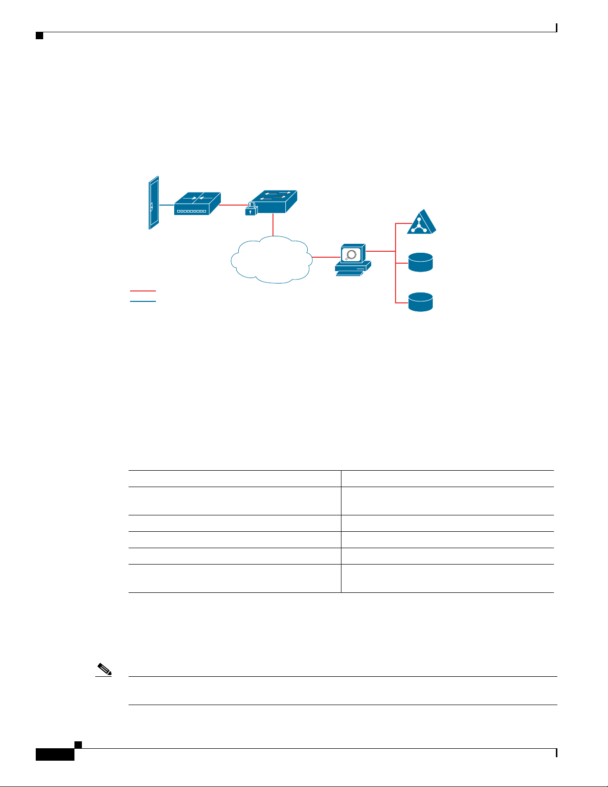
Cisco Physical Access Control is a comprehensive solution of hardware and software components,
connected through an IP network as shown in Figure 1-1.
Figure 1-1 Cisco Physical Access Control: System Overview
Chapter 1 Overview
Cisco Access
Gateway
POE
Ethernet
Low speed copper wiring
Access Layer
IP
Network
The Cisco Physical Access Gateway
A Cisco Physical Access Gateway is installed near each door to provide processing and control for the
connected door hardware, such as card readers, locks, and other input and output devices. This
architecture allows access control to be deployed incrementally, door by door, eliminating the central
panel and simplifying system design, wiring, and planning.
The Gateway is required, and can control up to two doors. Each Gateway supports the following:
Table 1-1 Cisco Physical Access Gateway Features and Benefits
switch
Cisco
Physical Access
Manager
LDAP/Microsoft
active directory
Other IT
apps
HR
database
187055
1-2
Feature Benefit
250,000 cardholder cache and a 150,000
Transaction buffer
Door continues to function in case network
connectivity is lost
Web server built in Simplifies configuration and monitoring
All communication is128 Bit AES encrypted Protects credentials, preserves security
Device pre-provisioning using network services Simplifies deployment
Plug & Play support Modules can be added or deleted without
disrupting service
If additional connections are required, you can connect up to 15 optional modules using a three-wire
Controller Area Network (CAN) bus. These modules can be added or removed without affecting the
operation of the system or other modules. See the “Optional Expansion Modules” section on page 1-5
for more descriptions of the available modules.
Note The modules are connected using the CAN1 interface. The CAN2 interface is not supported in this
release.
Cisco Physical Access Gateway User Guide
OL-20932-02
Page 11
Chapter 1 Overview
Related Documentation
For installation and configuration instructions, see Chapter 2, “Installing and Configuring the Cisco
Physical Access Gateway”.
See the Cisco Physical Access Manager User Guide for advanced configuration and management of
the access control components.
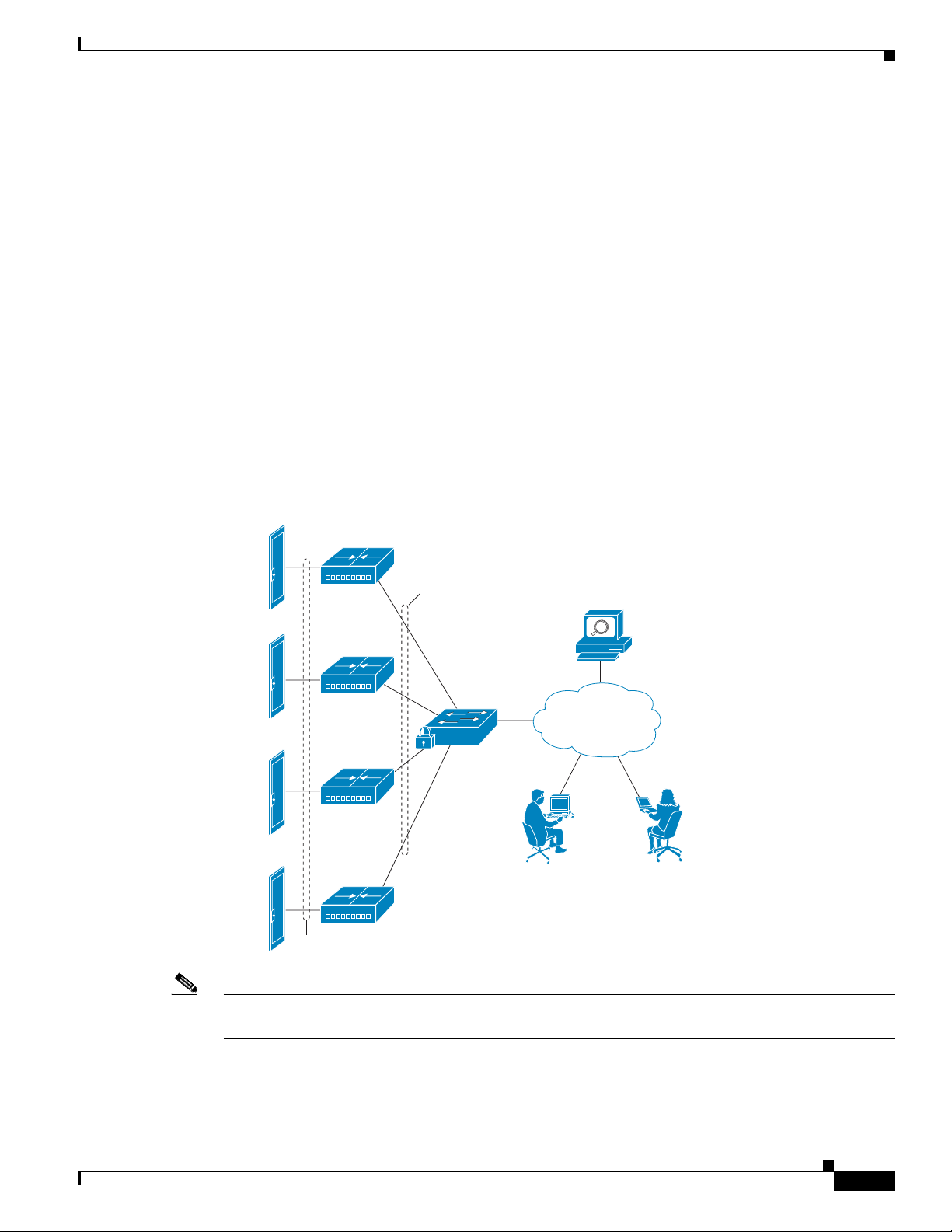
Support for Multiple Cisco Physical Access Gateways
A Cisco Physical Access Gateway is installed for each door, and connected to the IP network using an
Ethernet connection, as shown in Figure 1-2. This network connection provides communication with the
Cisco Physical Access Manager for advanced configuration, and management with the other Gateways
in the system. If the network connection is lost, the Gateway continues to provide access control
functionality for the connected door devices.
Figure 1-2 Multiple Cisco Physical Access Gateways
Doors and
Related Hardware
System Overview
Cisco Access
Gateways
Copper wiring
Ethernet/
POE
Access Layer
switch
Cisco Access Control Manager
Appliance (Cisco PAM)
IP
Network
Cisco PAM desktop
clients
187053
OL-20932-02
Note See the “Power Options and Requirements” section on page 1-12 for more information on support for
Power over Ethernet (PoE).
Cisco Physical Access Gateway User Guide
1-3
Page 12
System Overview
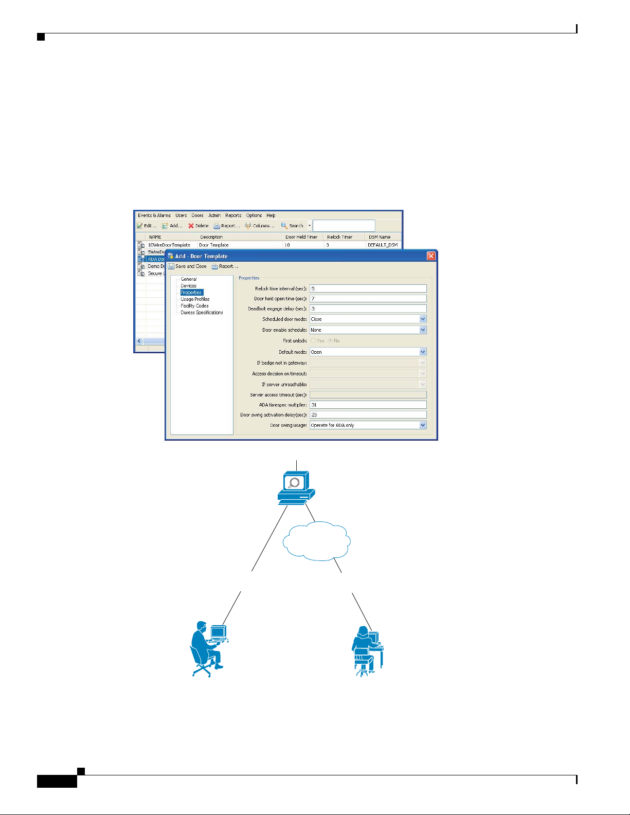
Cisco Physical Access Manager
The Cisco Physical Access Manager appliance (Cisco PAM) is a hardware and software solution that
provides advanced configuration, monitoring, and report generation for the entire system. Each Cisco
Physical Access Gateway is connected to the Cisco PAM appliance over an Ethernet-based IP network,
as shown in Figure 1-2 on page 1-3. A Java-based desktop application is installed on a PC connected to
the network, and used to configure and monitor the system, as shown in Figure 1-3.
Figure 1-3 Configuring and Monitoring Using the Cisco Physical Access Manager
Chapter 1 Overview
Cisco PAM Configuration Interface
Cisco PAM
Appliance
IP Network
Direct Ethernet
Connection
Cisco PAM
Desktop Software
(Java Thin Clients)
Network
Connection
271595
1-4
Cisco Physical Access Gateway User Guide
OL-20932-02
Page 13

Chapter 1 Overview
Optional Expansion Modules
The Cisco PAM appliance includes the following main features:
• 1 RU appliance
• Java thin client architecture
• Policy support: two-door, anti-passback
• Report generator (canned & custom)
• Badge design & enrollment
• Microsoft Active Directory integration
• Fine grained user rights
• Global I/O
• Device pre-provisioning
• Capacity & feature licenses
• IT data integration
• Warm standby high availability
• Audit trails
Related Documentation
For more information on the Cisco PAM appliance, including installation and configuration instructions,
see the Cisco Physical Access Manager User Guide.
Optional Expansion Modules
Each Cisco Physical Access Control system includes at least one Cisco Physical Access Gateway to
provide processing and connections for input and output devices such as card readers and locks. If
additional connections are required, you can add optional modules to extend the functionality of the
Gateway.
OL-20932-02
Cisco Physical Access Gateway User Guide
1-5
Page 14
Optional Expansion Modules
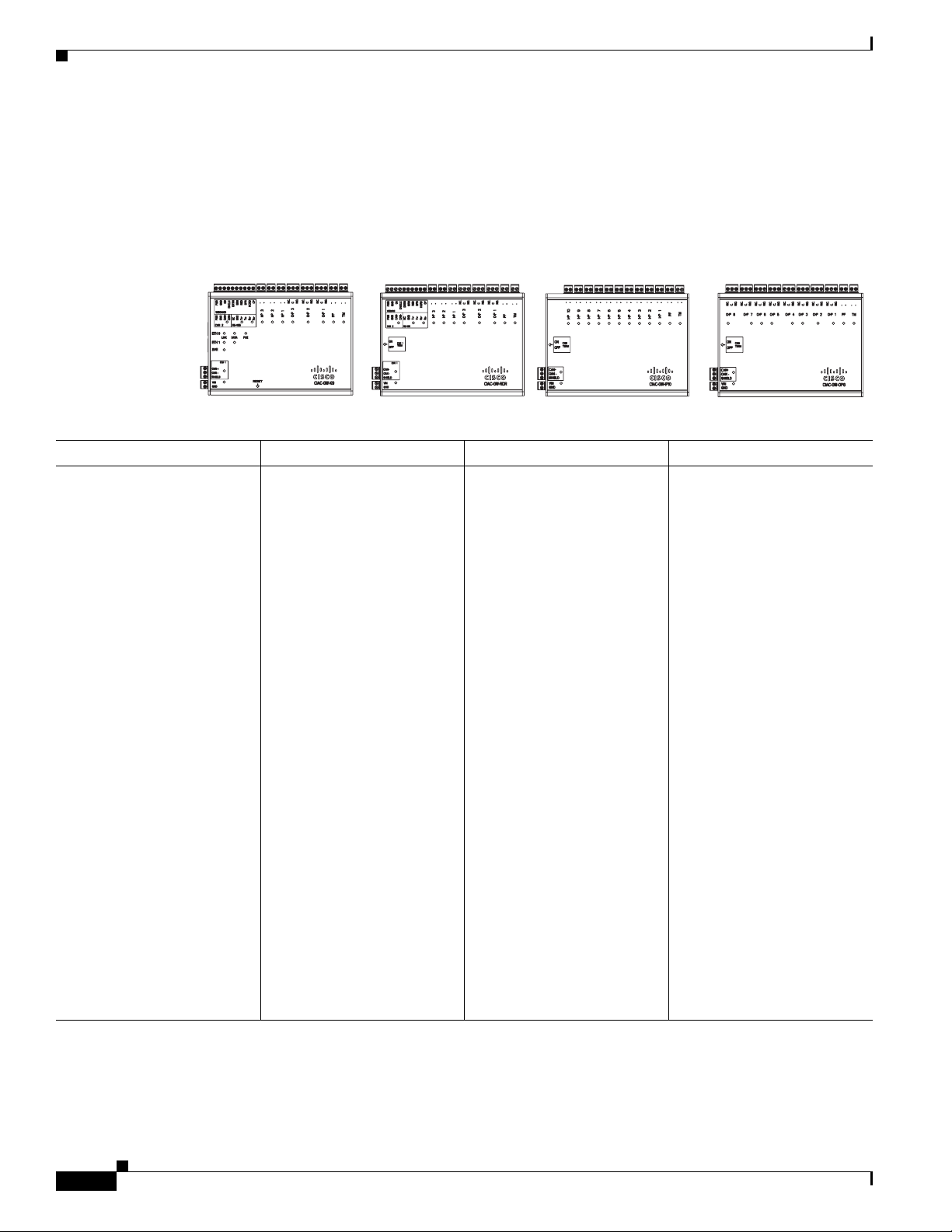
Module Features
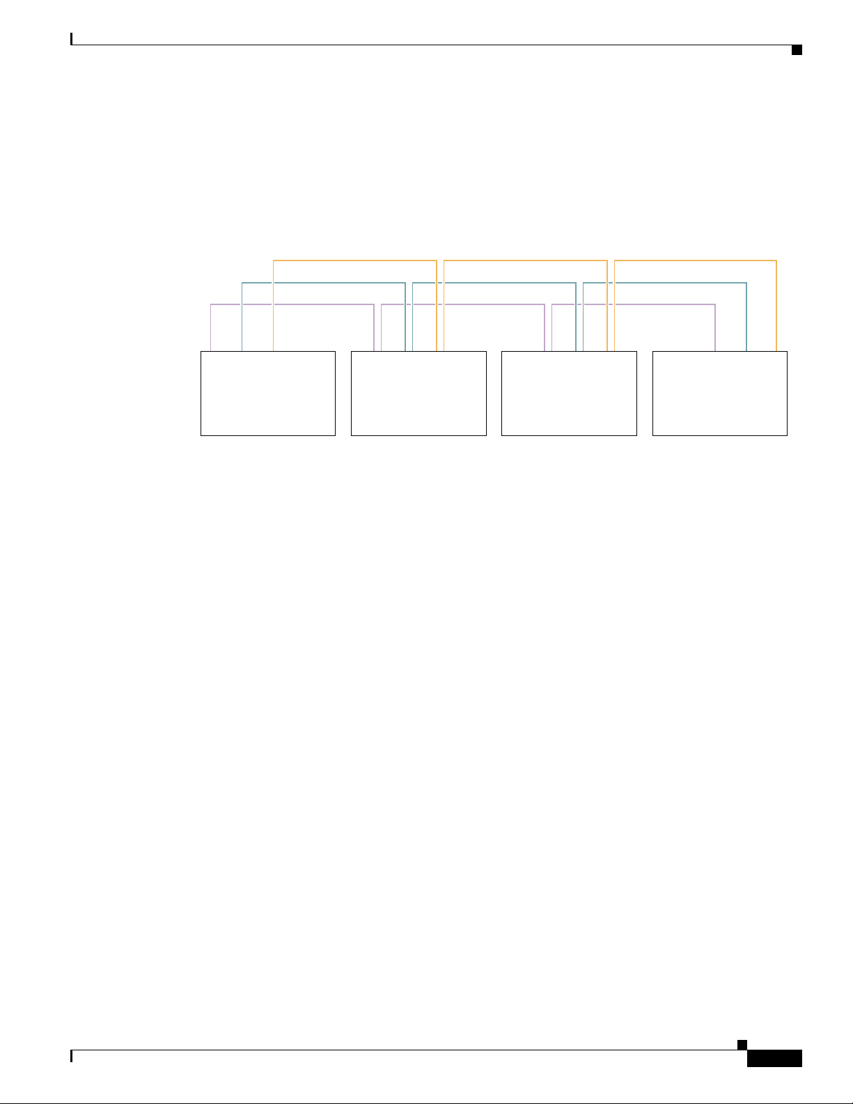
Figure 1-4 shows the modules for a Cisco Physical Access Control system.
Figure 1-4 Cisco Physical Access Gateway and the Optional Modules
Chapter 1 Overview
Cisco Physical
Access Gateway
Reader
Module
Input
Module
Output
Module
Gateway Cisco Reader Module Cisco Input Module Cisco Output Module
• Mandatory module.
• Connects up to two doors
using the 10 pin Wiegand
reader port, which can be
configured as two
five-pin ports.
• Connects up to 15
optional expansion
modules using a
three-wire CAN bus.
• Power-over-Ethernet
(POE) or 12 through 24V
DC
• Two Ethernet ports
• Three output ports:
Form C contacts rated at
5A 30VDC
• Three supervised input
• Tamper & Power Fail
ports
2
inputs (can be configured
as additional
• Requires connection to
an Access Gateway using
a three-wire CAN bus.
• Connects up to two doors
using the 10 pin Wiegand
reader port, which can be
configured as two 5 pin
ports.
• Power: 12 through 24V
1
DC
• Three output ports: Form
C contacts rated at 5A
30VDC
• Three supervised input
ports
• Tamper & Power Fail
inputs (can be configured
as additional
unsupervised inputs)
• One RS-485 serial port
(not supported in this
release).
• Requires connection to
an Access Gateway using
a three-wire CAN bus.
• 10 supervised input ports
• Example inputs are: Push
button switches, Glass
Break sensors, or any
contact closure input.
circuit
• Power: 12 through 24V
DC
• Tamper & Power Fail
inputs (can be configured
as additional
unsupervised ports)
• Requires connection to
an Access Gateway using
a three-wire CAN bus.
• 8 output ports: Form C
contacts rated at 5A
30VDC
• Example outputs are:
lights, LEDs, or any
contact closure output
circuit.
• Power: 12 through 24V
DC
• Tamper & Power Fail
inputs (can be configured
as additional
unsupervised ports)
unsupervised inputs)
• One RS-485 serial port
(not supported in this
release).
1. The modules are connected using the CAN1 interface. The CAN2 interface is not supported in this release.
2. A supervised input supports four states: normal, alarm, open and short. An unsupervised input only indicates normal or alarm.
1-6
Cisco Physical Access Gateway User Guide
OL-20932-02
Page 15
Chapter 1 Overview
CAN Bus Connections for Optional Modules
The optional modules are connected to a Cisco Physical Access Gateway using a CAN bus connection,
as shown in Figure 1-5.
Figure 1-5 CAN Bus Wiring
CAN+
Sheild
CAN-
Gateway Module Reader Module Input Module Output Module
Optional Expansion Modules
271589
Related Documentation
The CAN bus must adhere to the following rules:
• The maximum length for the CAN bus is 1320 feet (400 Metres).
• The last device in a CAN bus must be terminated by setting the CAN terminator switch to ON.
–
The CAN terminator switch in included on the Reader, Input and Output modules only (the
Gateway is always the first device in the CAN bus).
–
Set the terminator switch to OFF for all other modules in the CAN bus.
–
For the location of the CAN terminator on each device, see the physical port description for that
device.
• The Gateway and Reader modules are connected using the CAN1 interface. The CAN2 interface is
not supported in this release.
See the following chapters for instructions to install the modules and related equipment:
• Chapter 2, “Installing and Configuring the Cisco Physical Access Gateway”
• Chapter 3, “Connecting a Cisco Reader Module”
• Chapter 4, “Connecting a Cisco Input Module”
• Chapter 5, “Connecting a Cisco Output Module”
OL-20932-02
Cisco Physical Access Gateway User Guide
1-7
Page 16

Installation and Configuration Summary
Installation and Configuration Summary
The following steps are an example of the main installation and configuration tasks for a Cisco
Physical Access Control system. The exact procedure and order of installation for your system may vary.
Step 1 Unpack and mount the Cisco Physical Access Gateway.
Step 2 Unpack and mount optional reader, input or output modules, if necessary.
Step 3 Connect door readers, input and output devices to the Cisco Physical Access Gateway or optional
modules.
Step 4 Connect power to the Cisco Physical Access Gateway and any optional modules.
Step 5 Connect an Ethernet cable from a PC to the ETH1 interface on the Gateway module.
Note To enter the Gateway initial configuration, be sure to connect your PC to the ETH1 port. The
ETH0 port is used for network communication.
Step 6 Open a web browser on your PC and enter https://192.168.1.42. This URL opens the web-based
configuration page.
Chapter 1 Overview
Note Be sure to include the s in https://. This connects your browser to the secure URL.
Step 7 Enter the default username and password:
default username:
gwadmin
default password: gwadmin
Step 8 Enter and save the Network settings in the Initial Setup window. See the “Configuring and Managing the
Gateway Using a Direct Connection” section on page 2-15. Wait until the Gateway resets and the web
browser displays the screen Network Settings Applied.
Step 9 Verify the connections to the optional modules, door readers and other input and output devices.
Step 10 Connect an Ethernet cable from the Gateway ETH0 port to the IP network, and verify IP network
connectivity.
Step 11 Perform additional configuration, verification, and monitoring tasks as described in the Cisco Physical
Access Manager User Guide.
1-8
Cisco Physical Access Gateway User Guide
OL-20932-02
Page 17
Chapter 1 Overview
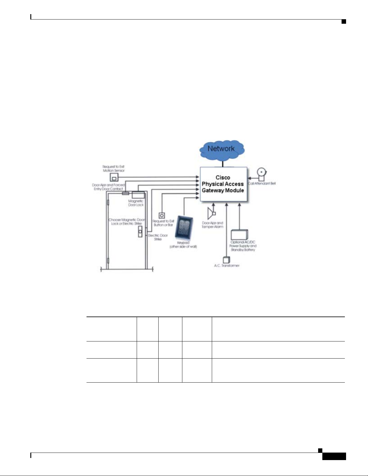
Door Device Wiring Requirements
The wires used for an access control door depend on the devices installed at the door. Before installing
the wiring for an access control system, do the following:
• Determine the number and type of door devices used at each door (as shown in Figure 1-6).
• Determine the number and type of wires used for each device, based on the descriptions in Tab le 1-2.
• Determine the length of the wires based on the distance between the device and the access control
Gateway, or optional module (such as a Reader, Output or Input module).
Figure 1-6 Air Return Using Ceiling Space or Using Ductwork
Door Device Wiring Requirements
OL-20932-02
Table 1-2 describes the wires used for typical input and output door devices. Refer to the device
documentation for more information and to verify the following requirements.
Table 1-2 Wires Used for Typical Door Devices
Typical
# of
Function
Request to Exit 2 22 Input Used to exit the door. This may be replaced by an
Door position
switch
Wires
2 22 Input Used to determine if door is open or closed. This
Wire
Gauge Type Use
egress crash bar if the exit is not alarmed.
device can cause a door forced open alarm after a
time out. This devise is usually supervised.
Cisco Physical Access Gateway User Guide
1-9
Page 18

Understanding Supervised and Unsupervised Input Devices
Table 1-2 Wires Used for Typical Door Devices (continued)
# of
Function
Wires
Reader 6 per
reader
Electric strike or
2 18 Output Opens the locking device. Include a reverse bias
magnetic lock
Alarm bypass 2 22 Output Optionally used to turn off the alarm contact at the
Bell or call 2 22 Input Optional call button that creates an event to notify a
Chapter 1 Overview
Typical
Wire
Gauge Type Use
22 Wiegand A reader device includes the following:
• 2 Wiegand data wires
• 1 LED
• 1 beeper
• 2 power (12VDC) wires (500 feet maximum
length)
diode or other surge suppressor to protect against
reverse current. See the “Installing Surge
Suppressors on Output Device Connections”
section on page 1-13 for more information.
door while the strike is energized.
CPAM user that a person is trying to get in the door.
Understanding Supervised and Unsupervised Input Devices
Door input devices can be supervised or unsupervised
• Unsupervised input devices have two states: active or inactive.
• Supervised input devices have four states: active, inactive, short, and open.
Unsupervised inputs have limited functionality. If a wire is cut or shorted between the input module and
a normally open device. The server cannot determine the change and the device would remains in
inactive state even when the switch is closed.
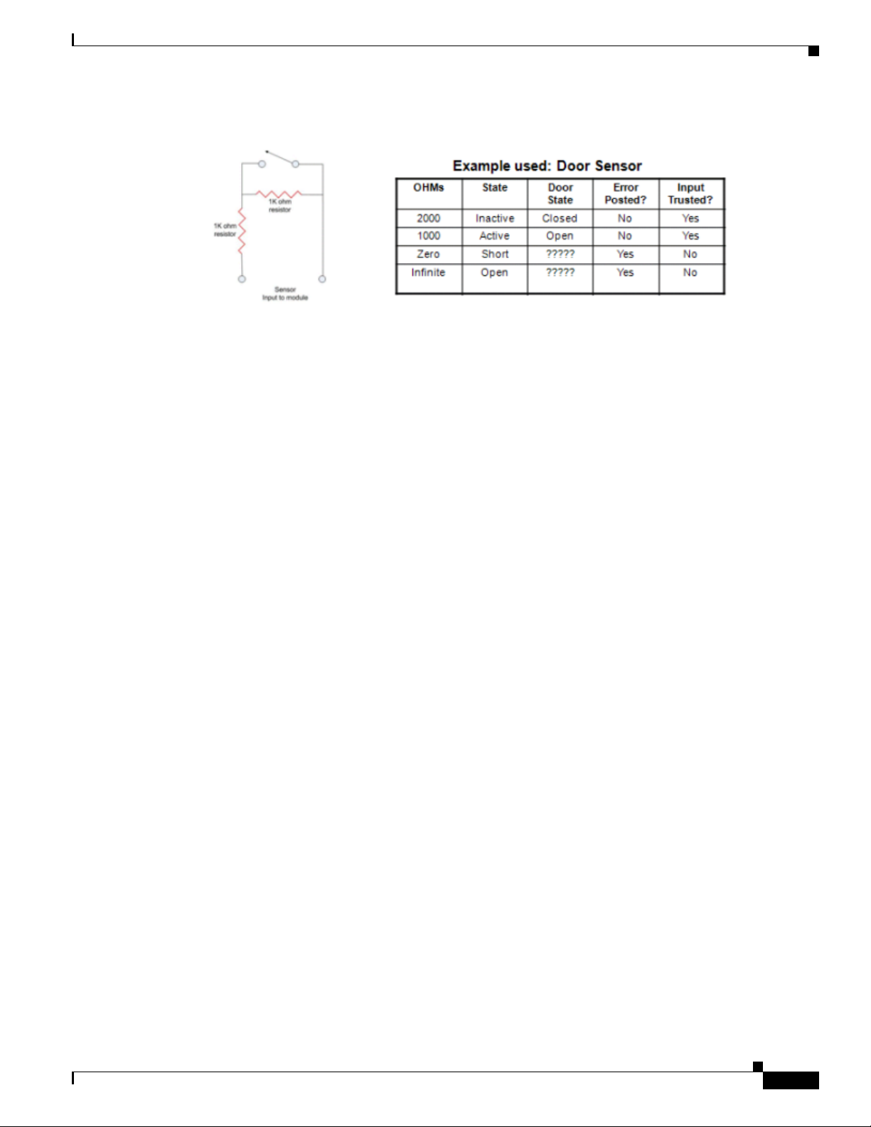
To make the input device supervised, use two 1K resistors in the circuit (Figure 1-7).
• In the inactive state, the circuit measures 2000 ohms.
• In the active state, the circuit measures 1000 ohms.
• In the short state the circuit measures 0 ohms
• In the open state the circuit measures infinite ohms.
Once the input device is supervised, CPAM can determine if a wire is cut or shorted.
Note You must also configure the device as supervised in CPAM. See the Cisco Physical Access Manager User
Guide for more information.
1-10
Cisco Physical Access Gateway User Guide
OL-20932-02
Page 19
Chapter 1 Overview
Understanding Supervised and Unsupervised Input Devices
Figure 1-7 Example of a Supervised Door Sensor
OL-20932-02
Cisco Physical Access Gateway User Guide
1-11
Page 20

Power Options and Requirements
Power Options and Requirements
This section includes the following information:
• Power Options
• Current Draw Requirements
• Installing Surge Suppressors on Output Device Connections
• Connect Reader Devices with Module Power Off
Power Options
Table 1-3 summarizes the power options for each module. The Cisco Physical Access Gateway supports
Power over Ethernet (PoE) and DC power. All other modules support DC power only.
• The DC power connections on each module are Voltage In (VIN) and Ground (GND).
• For information on configuring PoE, see the documentation for your network switch. Your switch
must support PoE and be properly configured to use this feature with the Cisco Physical Access
Gateway.
Chapter 1 Overview
Table 1-3 Power Options for the Cisco Physical Access Control Modules
Module Power over Ethernet (PoE) 12 through 24V DC
Cisco Physical Access Gateway Supported Supported
Cisco Reader Module Not Supported Supported
Cisco Input Module Not Supported Supported
Cisco Output Module Not Supported Supported
Current Draw Requirements
Each Cisco Physical Access Control module requires a minimum amount of available power, as
described in Table 1-4. The current draw requirements listed in Table 1-4 account for inefficiencies in
power supplies and are to be used for power budgeting. The requirements do not represent actual power
usage.
Table 1-4 Current Draw Requirements for the Cisco Physical Access Control Modules
Module
Cisco Physical Access Gateway 1.5A 1.5A is required for the Gateway module only.
Cisco Reader Module 1A 1A is required for the Reader module only. Add
Cisco Input Module 1A N/A
Cisco Output Module 1A N/A
Current Draw
Requirement Notes
Add an additional 1A if a reader or lock is
attached to the module.
an additional 1A if a reader or lock is attached to
the module.
1-12
Cisco Physical Access Gateway User Guide
OL-20932-02
Page 21
Chapter 1 Overview
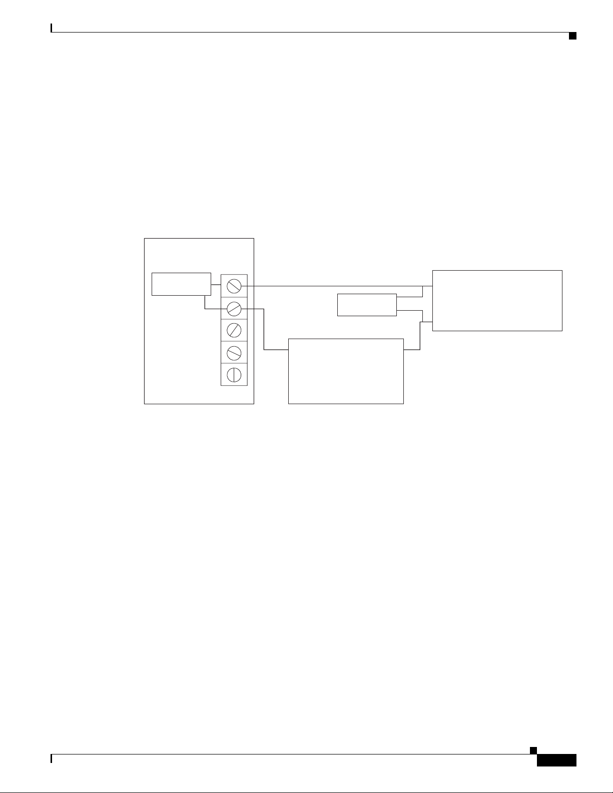
Installing Surge Suppressors on Output Device Connections
Install a surge suppressor between all output devices and the Gateway, Reader, or Output modules to
protect the devices from power surges. Use one of the following methods:
• If the base on a lock device receives power from an external power source, install an isolation relay
between the output device and the Gateway, Reader, or Output module.
• Install a MOV (Metal Oxide Varistor) surge protection product, such as the Ditek DTK-ESS Electric
Switch Suppressor kit from Diversified Technology Group. An example installation is shown in
Figure 1-8. You can also use a diode 4N4001 for surge suppression.
Figure 1-8 Sample Surge Suppressor Installation
Cisco Access
Control Module
Power Options and Requirements
Surge
Suppressor
Surge
Suppressor
+-
Power Source
Terminal Strip
Connect Reader Devices with Module Power Off
Disconnect power from the Gateway or Reader module before connecting reader devices to the modules.
Connecting a reader device when the modules are powered can cause the Gateway or Reader module to
malfunction.
+
Output Device
-
277557
OL-20932-02
Cisco Physical Access Gateway User Guide
1-13
Page 22
Mounting a Gateway or Optional Module
Mounting a Gateway or Optional Module
Each Cisco Physical Access Gateway and optional module includes two mounting brackets and four
screws to mount the Gateway to the wall.
Wall Mounting a Gateway or Optional Module
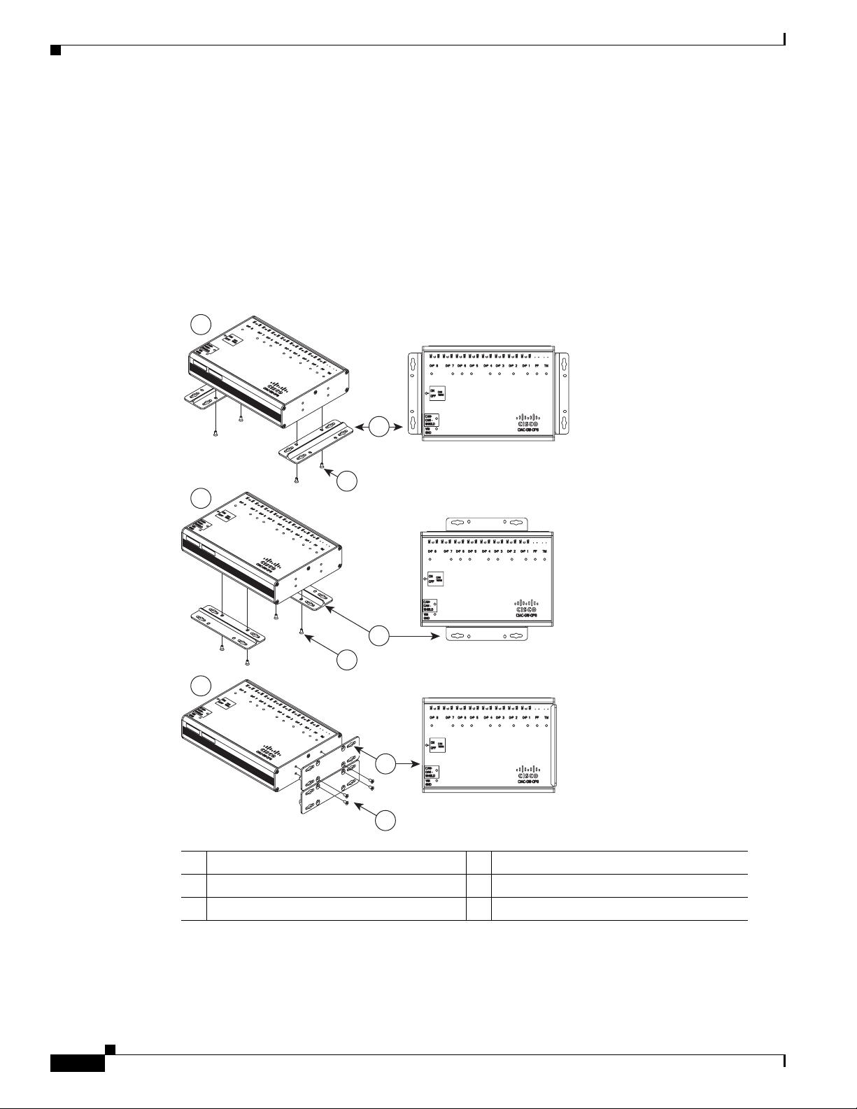
Figure 1-9 shows the three options for attaching the included wall-mount brackets to a module.
Figure 1-9 Three Options for Installing Wall Mount Brackets
1
4
Chapter 1 Overview
5
2
4
5
3
4
187050
5
1 Option 1: Bottom end mounting 4 Mounting Brackets (included)
2 Option 2: Bottom side mounting 5 Screws
3 Option 3: Side mounting
1-14
Cisco Physical Access Gateway User Guide
OL-20932-02
Page 23

Chapter 1 Overview
Wall Mount Installation Kit Contents
Each module includes a wall mount installation kit that contains the following:
Table 1-5 Wall Mount Installation Kit Contents
Hardware Item Quantity
Wall Mount brackets 2
Screws 8
Mounting a Gateway or Optional Module
OL-20932-02
Cisco Physical Access Gateway User Guide
1-15
Page 24

Mounting a Gateway or Optional Module
Chapter 1 Overview
1-16
Cisco Physical Access Gateway User Guide
OL-20932-02
Page 25

Contents
CHAP T ER
2
Installing and Configuring the Cisco Physical Access Gateway
This chapter includes the following information:
• Overview, page 2-2
• Package Contents, page 2-3
• Physical Overview and Port Description, page 2-3
• Installing the Cisco Physical Access Gateway, page 2-7
• Configuring and Managing the Gateway Using a Direct Connection, page 2-15
–
Understanding Network Time Protocol (NTP) Settings, page 2-15
–
Connecting a PC to the Gateway, page 2-16
–
Entering the Gateway Network Settings, page 2-17
OL-20932-02
–
Changing the User Password, page 2-19
–
Upgrading the Gateway Firmware Using a Direct Connection, page 2-20
–
Displaying Serial Numbers and Other Information, page 2-22
• Configuring the Gateway Using the Cisco Physical Access Manager, page 2-23
• Resetting the Cisco Physical Access Gateway, page 2-24
Cisco Physical Access Gateway User Guide
2-1
Page 26
Overview
Overview
Chapter 2 Installing and Configuring the Cisco Physical Access Gateway
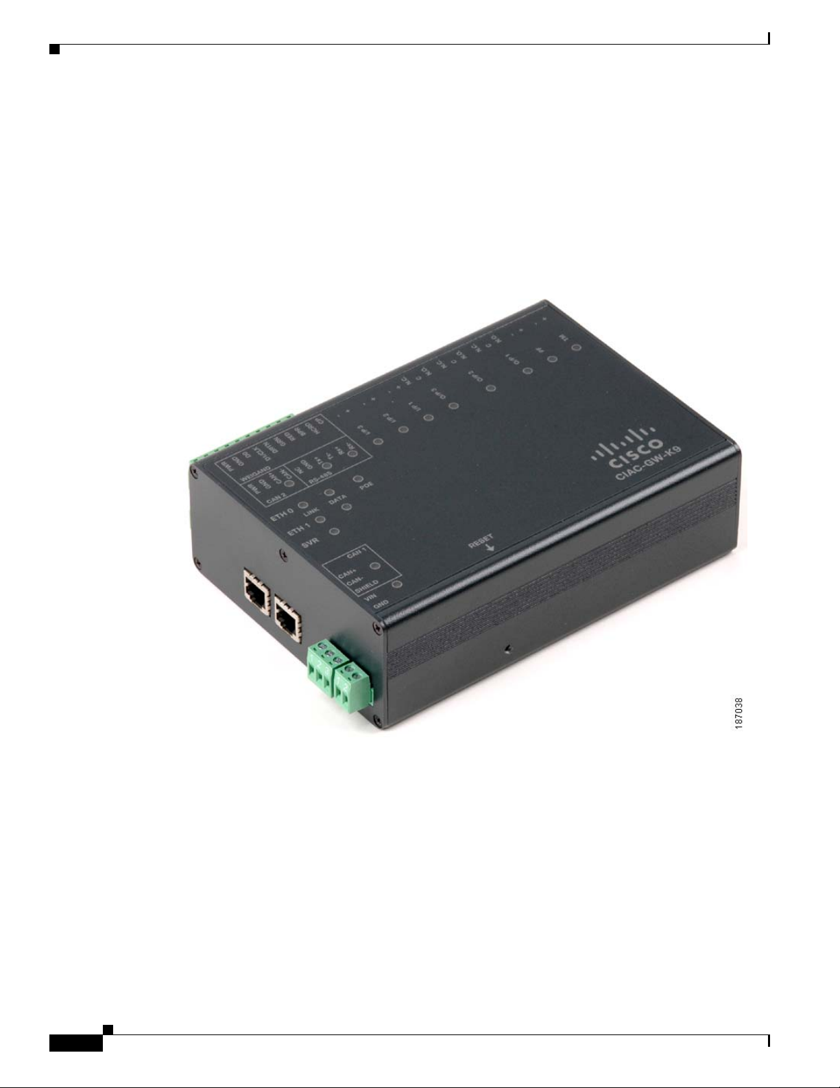
The Cisco Physical Access Gateway (Figure 2-1) is installed near each door to provide access control
and connections for card readers, door locks and other input and output devices. The Gateway is
connected to the Cisco Physical Access Manager using an Ethernet connection to the IP network. Power
is supplied through a Power over Ethernet (PoE) connection, or using a DC power source. Each Gateway
includes connections for up to two Wiegand door readers, three input devices, and three output devices.
Optional expansion modules are available to add additional doors and devices to the Gateway.
Figure 2-1 Cisco Physical Access Gateway
2-2
Cisco Physical Access Gateway User Guide
OL-20932-02
Page 27
Chapter 2 Installing and Configuring the Cisco Physical Access Gateway
Package Contents
Each Cisco Physical Access Gateway includes the following:
• Six End-Of-Line (EOL) 1K termination resistors (used for supervised input interfaces)
• Two mounting brackets, with 4 screws for each bracket
• Regulatory compliance and safety information
• Quick Start guide
• Connector plugs, including the following:
Type Quantity
10 Pin 1
3 Pin 4
2 Pin 6
Package Contents
Physical Overview and Port Description
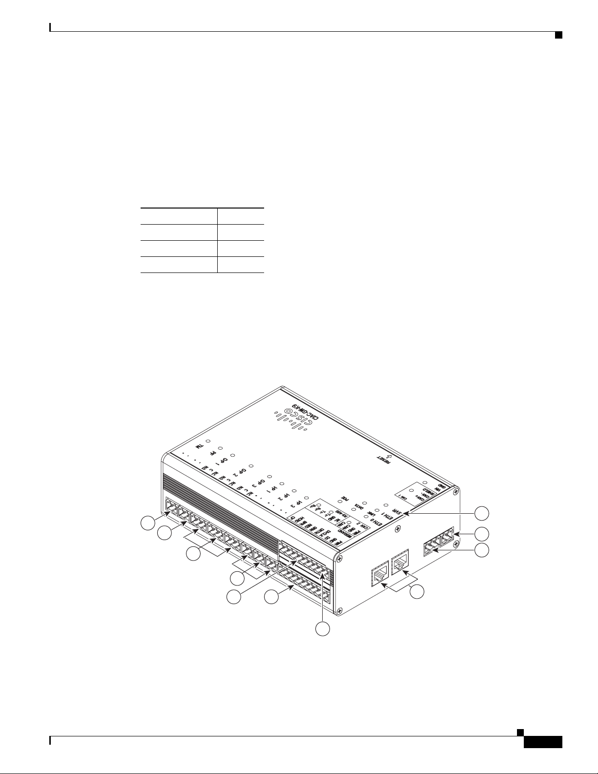
Figure 2-2 and Figure 2-3 show the location of each port, including connections for power, Ethernet,
door readers and other input and output devices.
Figure 2-2 Cisco Physical Access Gateway Ports and Connectors: Side View
10
9
8
7
5
6
3
1
2
4
OL-20932-02
2
Cisco Physical Access Gateway User Guide
187040
2-3
Page 28
Physical Overview and Port Description
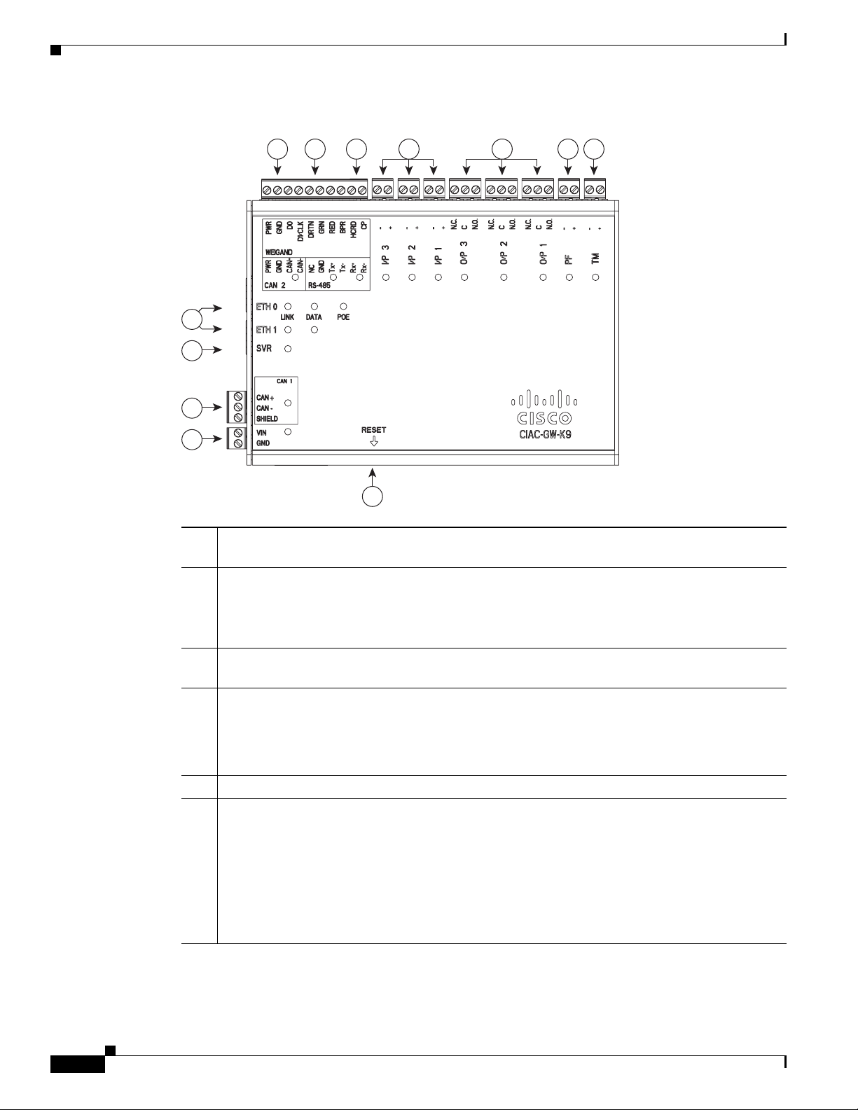
Figure 2-3 Cisco Physical Access Gateway Ports and Connectors: Top View
4
3
2
1
Chapter 2 Installing and Configuring the Cisco Physical Access Gateway
2 5 6 7 8 9 10
187039
11
1 Power—Two-pin connector for Voltage In (VIN) and Ground (GND) to connect a 12 to 24 VDC
external power source.
2 CAN—A three-wire CAN bus is used to connect additional modules, including the Cisco Reader
Module, Cisco Input Module, and Cisco Output Module.
Note Modules are connected using the CAN1 interface. The CAN2 interface is not supported
in this release.
3 SVR (Server)—When the LED is steady green, the Gateway is connected to a Cisco PAM
appliance.
4 Fast Ethernet interfaces—There are two 10/100 BASE-TX RJ-45 connectors:
• ETH 0: connects the Gateway to the network. ETH 0 also supports Power over Ethernet
(PoE) for the device (optional).
• ETH 1: connects the device to a PC to access the device configuration web page.
5 Serial interface—The RS-485 interface is not supported in this release.
6 Wiegand interface—This interface can be configured as the following:
• One 10-pin Wiegand/clock and data reader interface to connect a single door reader.
• Two 5-pin Wiegand/clock and data interfaces to connect two door readers (for installations
where a 5-pin interface is sufficient).
Note Disconnect power from the Gateway or Reader module before connecting reader devices
to the modules. Connecting a reader device when the modules are powered can cause the
Gateway or Reader module to malfunction.
2-4
Cisco Physical Access Gateway User Guide
OL-20932-02
Page 29

Chapter 2 Installing and Configuring the Cisco Physical Access Gateway
7 Input interfaces—Three input interfaces used to sense the contact closure. Each input can be
configured as supervised or unsupervised and can be configured to sense a Normally Open (NO)
or Normally Closed (NC) contact.
• An unsupervised input senses a simple contact closure state, including Normal or Alarm.
When connected to open contacts, the terminal voltage range is 4V to 5V. For closed
contacts, the voltage range is 0V to 0.7V.
• A supervised input senses four contact states, including Normal, Alarm, Open and Short.
These inputs require 1K End-Of-Line (EOL) termination resistors installed at the contacts
(two resistors are included in the accessory kits for each Input port).
8 Output interfaces—Three Form C (5A @ 30V) relay output interfaces. Each output connection
can be configured as either Normally Closed (NC) or Normally Open (NO).
• C & NO connection: The relay is normally open. The circuit is closed when triggered.
• C & NC connection: The relay is normally closed. The circuit is opened when triggered.
Notes:
• Install surge protection between the output device and the Cisco PAM module, as described
in the “Installing Surge Suppressors on Output Device Connections” section on page 1-13.
• Common (C) is always used, and either NC or NO is used to complete the connection.
• All Generic Output devices installed in Cisco PAM systems prior to release 1.1.0, were
connected to the Gateway, Reader, or Output modules with the wiring reversed. If upgrading
to Cisco PAM release 1.1.0 from an earlier release, disconnect all Generic Output devices
and do the following:
Physical Overview and Port Description
LED Status
–
Connect Normally Open devices to the N.O. and C connectors on the Gateway, Reader,
or Output module.
–
Connect Normally Closed devices to the N.C. and C connectors on the Gateway, Reader,
or Output module.
9 PF—Power fail input: an unsupervised input that raises a “power fail” alarm when the circuit is
open. Can be configured as an additional unsupervised port. An unsupervised input indicates
only normal or alarm. The corresponding LED is red when circuit is open (when no input is
connected).
10 TM—Tamper input: an unsupervised input that raises a “tamper” alarm when the circuit is open.
Can be configured as an additional unsupervised port. An unsupervised input indicates only
normal or alarm. The corresponding LED is red when circuit is open (when no input is
connected).
11 Reset—Resets the device. See the “Resetting the Cisco Physical Access Gateway” section on
page 2-24 for more information.
Table 2-1 describes the Gateway module status LEDs:
Table 2-1 Gateway LEDs
Status Description
SVR
Steady Green The Gateway is connected to a Cisco PAM appliance.
OL-20932-02
Cisco Physical Access Gateway User Guide
2-5
Page 30

Physical Overview and Port Description
Table 2-1 Gateway LEDs (continued)
Status Description
Input Port LEDs
OFF Input is not configured
GREEN Input is configured and in normal state
BLINKING GREEN Input is configured, and is receiving and alarm or other data.
BLINKING RED Input is configured, short
RED Input is configured, open
Output Port LEDs
Off Output not configured
Solid Green Output configured and in default state
Blinking Green Output configured and active
Chapter 2 Installing and Configuring the Cisco Physical Access Gateway
2-6
Cisco Physical Access Gateway User Guide
OL-20932-02
Page 31

Chapter 2 Installing and Configuring the Cisco Physical Access Gateway
Installing the Cisco Physical Access Gateway
Installing the Cisco Physical Access Gateway
• Before You Begin, page 2-7
• Procedure, page 2-7
Before You Begin
Before you install a Cisco Physical Access Gateway, verify the following:
• Verify that the module has access to a power source. See the “Power Options and Requirements”
section on page 1-12 for more information.
• Verify that you have the necessary mounting brackets or other hardware. See the “Mounting a
Gateway or Optional Module” section on page 1-14.
Procedure
To install the Cisco Physical Access Gateway, perform the following procedure:
Step 1 Mount the Gateway to a wall. See the “Mounting a Gateway or Optional Module” section on page 1-14
for more information.
Step 2 Connect the Gateway to a power source.
• If using a DC power source, insert a two-pin connector plug into the DC power port (Figure 2-4),
and connect the Voltage In (VIN) and ground (GND) wires.
• If using PoE, connect an Ethernet cable from the IP network to the ETH0 port (Figure 2-4).
See the “Power Options and Requirements” section on page 1-12 for more information.
OL-20932-02
Cisco Physical Access Gateway User Guide
2-7
Page 32

Installing the Cisco Physical Access Gateway
Chapter 2 Installing and Configuring the Cisco Physical Access Gateway
Figure 2-4 Power Connections for the Cisco Physical Access Gateway
271594
1
2
3
1 DC power GND (ground)— Connects the DC ground wire to the Gateway.
2 DC power Voltage In (VIN)—Connects the DC Voltage In (VIN) wire to the Gateway.
3 ETH0 for PoE—Connects the Ethernet cable from the Access Layer switch to the Gateway. To
use this power option, the switch must support PoE.
Step 3 Connect one or two door reader devices to the Wiegand interface using one of the following
configurations:
• Connect a single door reader using all 10 Wiegand interface pins.
• Connect one or two door readers using 5-pin Wiegand interface connections (for installations where
a 5-pin interface is sufficient).
2-8
Cisco Physical Access Gateway User Guide
OL-20932-02
Page 33

Chapter 2 Installing and Configuring the Cisco Physical Access Gateway
Figure 2-5 shows the location of the Wiegand interface connections. The table describes the connections
for 10-pin and 5-pin reader interface connections. The wire connectors from the reader device are shown
in parentheses. If attaching a second reader, use the alternative connections shown in the column on the
far right.
Figure 2-5 Wiegand Interface on the Gateway and Reader Modules
Installing the Cisco Physical Access Gateway
10
8
9
6
7
4
5
2
271603
3
1
Chassis
Label Description
1 PWR +12v PWR (red)
One Reader
10 Wire Connection
1
First Reader in a
5 Wire Connection
Second Reader in a
5 Wire Connection
PWR (red) PWR (red)
2 GND Ground GND (black) GND (black) GND (black)
3 D0 Data 0 D0 (green) D0 (green) ----------
4 D1/CLCK Data 1 D1/CLCK (white) D1/CLCK (white) ----------
5 DRTN Shield DRTN (shield) DRTN (shield) DRTN (shield)
6 GRN Output
7 RED Output RED (brown) ----------
8 BPR Output
(Beeper)
2
GRN (orange) GRN (orange) ----------
3
BPR (yellow)
---------- ----------
(yellow)
GRN (orange)
OL-20932-02
Cisco Physical Access Gateway User Guide
2-9
Page 34

Installing the Cisco Physical Access Gateway
Chapter 2 Installing and Configuring the Cisco Physical Access Gateway
Chassis
Label Description
9 HCRD Hold
One Reader
10 Wire Connection
HCRD (blue) ---------- D1/CLCK (white)
Control
10 CP Card
CP (purple) ---------- D0 (green)
Present
1. Wire colors are shown in parentheses.
2. Outputs show the LED color and reader wire color (in parentheses). For example, “GRN (orange)” supports a green LED.
Attach the orange wire from the reader device.
3. ---------- means the wire slot is not used.
Step 4 Connect input devices to the Gateway:
a. Insert two-pin connector plugs into the input ports (see Figure 2-7).
b. (Optional, for supervised input connections only). Install two End-Of-Line (EOL) 1K termination
resistors in each supervised input interface (one terminator in each connector). Figure 2-6 shows the
terminator installation for a Normally Closed (NC) and Normally Open (NO) input connection.
Figure 2-6 Input Connections: Cisco Physical Access Gateway and Reader Module
1K,, 1%
1K,, 1%
First Reader in a
5 Wire Connection
NC
Second Reader in a
5 Wire Connection
2-10
Connect the wires from the input devices (see Figure 2-7).
c.
Note Each of the input connections can be configured as supervised or unsupervised. The tamper and
power fail inputs can be configured as additional unsupervised ports. A supervised input
supports four states: normal, alarm, open and short. An unsupervised input indicates only normal
or alarm.
Cisco Physical Access Gateway User Guide
1K,, 1%
1K,, 1%
NO
187838
OL-20932-02
Page 35

Chapter 2 Installing and Configuring the Cisco Physical Access Gateway
Figure 2-7 Input Connections: Cisco Physical Access Gateway and Reader Module
Installing the Cisco Physical Access Gateway
271592
3 4 1 21 21 2
1 Positive Input Connections—Positive connection to an Input device.
2 Ground Input Connections—Ground connection to an Input device.
3 TM—Tamper input: an unsupervised input that raises a “tamper” alarm when the circuit is open.
Can be configured as a general input device using the Cisco Physical Access Manager. An
unsupervised input indicates only normal or alarm. The corresponding LED is red when circuit
is open (when no input is connected).
4 PF—Power fail input: an unsupervised input that raises a “power fail” alarm when the circuit is
open. Can be configured as an additional unsupervised port. An unsupervised input indicates
only normal or alarm. The corresponding LED is red when circuit is open (when no input is
connected).
Step 5 Connect output devices to the Gateway (Figure 2-8). Each of the three Form C (5A @ 30V) relay output
connections can be configured as either Normally Closed (NC) or Normally Open (NO).
a. Insert three-pin connector plugs into the output ports.
b. Connect the wires from the output devices.
–
Common (C) is always used, and either NC or NO is used to complete the connection.
–
If the relay is normally open, use the C & NO connections. The circuit is closed when triggered.
OL-20932-02
–
If the relay is normally closed, use the C & NC connections. The circuit is opened when
triggered.
Cisco Physical Access Gateway User Guide
2-11
Page 36

Installing the Cisco Physical Access Gateway
Figure 2-8 Output Connections: Cisco Physical Access Gateway and Reader Module
Chapter 2 Installing and Configuring the Cisco Physical Access Gateway
31 2 31 2 31 2
1 Normally Open (N.O.) connection 3 Normally Closed (N.O.) connection
2 C
Step 6
Connect optional expansion modules to the Gateway, if necessary:
a. Insert a three-pin connector plug into the CAN1 port, as shown in Figure 2-9.
b. Connect the CAN wires to the CAN bus, as shown in Figure 2-10.
c. On the last device in the CAN bus, set the CAN terminator switch to ON. The CAN terminator
switch in included on the Reader, Input and Output modules only (the Gateway is always the first
device in the CAN bus). Set the terminator switch to OFF for all other modules in the CAN bus.
Note Modules are connected using the CAN1 interface. The CAN2 interface is not supported in this release.
271593
2-12
Cisco Physical Access Gateway User Guide
OL-20932-02
Page 37

Chapter 2 Installing and Configuring the Cisco Physical Access Gateway
Figure 2-9 CAN1 Connections: Cisco Physical Access Gateway and Reader Module
Installing the Cisco Physical Access Gateway
271590
1
2
3
1 CAN+
Connects to the positive terminal of the CAN bus.
2 CAN-
Connects to the negative terminal of the CAN bus.
3 Shield
Connects to GND and/or Shield.
Figure 2-10 CAN Bus Wiring
CAN+
Sheild
CAN-
Gateway Module Reader Module Input Module Output Module
271589
OL-20932-02
Note On the last device in the CAN bus, set the CAN terminator switch to ON. The CAN terminator switch
in included on the Reader, Input and Output modules only (the Gateway is always the first device in the
CAN bus).
Cisco Physical Access Gateway User Guide
2-13
Page 38

Installing the Cisco Physical Access Gateway
Step 7 Connect the Gateway to the IP network by connecting an Ethernet cable to the ETH0 port, as shown in
Figure 2-11.
Figure 2-11 ETH 0 Ethernet Connection for the Cisco Physical Access Gateway
Chapter 2 Installing and Configuring the Cisco Physical Access Gateway
271591
Step 8
1
1 ETH0—Ethernet port for connecting the Gateway to the IP network.
Note The ETH0 connection can also be used for Power over Ethernet.
Note The ETH1 port is used to connect a PC to the Gateway for configuration and monitoring.
See the “Configuring and Managing the Gateway Using a Direct Connection” section on
page 2-15 for more information.
Continue to the “Configuring the Gateway Using the Cisco Physical Access Manager” section on
page 2-23.
2-14
Cisco Physical Access Gateway User Guide
OL-20932-02
Page 39

Chapter 2 Installing and Configuring the Cisco Physical Access Gateway
Configuring and Managing the Gateway Using a Direct Connection
Configuring and Managing the Gateway Using a Direct
Connection
To enable the Gateway communication with the Cisco PAM appliance, connect a PC to the ETH1 port
and use a web browser to enter basic network settings, as described in this section. You can also use the
web administration tool to perform basic administration and monitoring tasks, such as upgrading the
module firmware or displaying the module serial number.
This section includes the following information:
• Understanding Network Time Protocol (NTP) Settings
• Connecting a PC to the Gateway
• Entering the Gateway Network Settings
• Changing the User Password
• Upgrading the Gateway Firmware Using a Direct Connection
• Displaying Serial Numbers and Other Information
Tip You can also use the Cisco PAM desktop software to enter network settings and upgrade firmware
images. See the “Configuring the Gateway Using the Cisco Physical Access Manager” section on
page 2-23.
Understanding Network Time Protocol (NTP) Settings
Cisco Systems strongly recommends using a network time protocol (NTP) server to synchronize the date
and time clock on each Gateway module, and on the Cisco PAM appliance. This ensures that events and
messages between the server and the Gateway modules are in sync. If the time and date are not
synchronized, inconsistent system behavior can occur.
We strongly recommend using the same NTP server setting for the Cisco PAM appliance, and for all
Gateway modules.
• Gateways can receive the NTP server setting from a DHCP server, or by using the Cisco PAM
desktop software.
–
To enter the Gateway DHCP settings, see the “Entering the Gateway Network Settings” section
on page 2-17.
–
If DHCP is used to define the Gateway NTP server, any NTP settings defined using the
Cisco PAM desktop software will not apply (the DHCP configuration takes precedence).
–
To enter the NTP setting for a single Gateway using Cisco PAM desktop software, choose
Hardware from the Doors menu, right-click a Gateway module, and choose Set Gateway
Address.
OL-20932-02
–
Beginning with Cisco PAM Release 1.3.0, you can also change the NTP server setting for
multiple Gateways (Right-click the Access GW Driver and choose the Set NTP Server
command). See the Cisco Physical Access Manager User Guide for instructions.
• To enter the NTP setting on the Cisco PAM server, use the Cisco PAM web administration tool. See
the Cisco Physical Access Manager User Guide for instructions.
Cisco Physical Access Gateway User Guide
2-15
Page 40

Configuring and Managing the Gateway Using a Direct Connection
Note Other systems that are integrated with Cisco PAM, such as the Video Surveillance Manager (Cisco
VSM), should use the same NTP server setting.
Connecting a PC to the Gateway
To enter the initial Gateway settings or perform other administration tasks, connect a PC to the Gateway
ETH1 port and use a web browser to access the administration pages.
Before You Begin
To configure a Cisco Physical Access Gateway, you need the following:
• A PC and web browser.
The Cisco Physical Access Gateway supports Internet Explorer 6.0 and higher.
• A Ethernet cable to connect your PC to the Gateway.
Cross-over and straight-through cables are supported.
• Your PC must be configured to connect to the 192.168.1.0 network using Ethernet. Use any static
host address on the network other than 192.168.1.42.
• Power connected to the Cisco Physical Access Gateway.
See the “Installing the Cisco Physical Access Gateway” section on page 2-7 for more information.
Chapter 2 Installing and Configuring the Cisco Physical Access Gateway
In addition, gather the following information:
• The IP Address of the Cisco PAM appliance.
• You can use a DHCP server to assign an IP address for the Gateway.
If a DHCP server is not used, gather the Cisco Physical Access Gateway IP address, IP gateway,
subnet mask.
• The domain name server (DNS) for the Gateway if DNS names (not IP addresses) are used for the
NTP or Cisco PAM addresses.
Procedure
Complete the following steps to log on to the administration tool.
Step 1 Connect an Ethernet cable from a PC to the ETH1 interface on the Gateway module.
• See the “Physical Overview and Port Description” section on page 2-3 for the port location.
• Be sure to connect your PC to the ETH1 port. The ETH0 port is used for network communication.
• Your PC must be configured to connect to the 192.168.1.0 network using Ethernet. Use any static
host address on the network other than 192.168.1.42.
Step 2 Open a web browser on your PC and enter https://192.168.1.42. to access the web-based
administration pages.
Step 3 Enter the default username and password (Figure 2-12).
default username:
gwadmin
2-16
default password: gwadmin
Cisco Physical Access Gateway User Guide
OL-20932-02
Page 41

Chapter 2 Installing and Configuring the Cisco Physical Access Gateway
Figure 2-12 Login Screen for the Cisco Physical Access Gateway
The web administration pages appear, and are described in the following sections.
Entering the Gateway Network Settings
Configuring and Managing the Gateway Using a Direct Connection
Enter the network settings to enable IP communication between the Gateway and the Cisco PAM
appliance. Network settings include the following:
• ETH0 Configuration: the ETH0 port provides IP network connectivity with the Cisco PAM
appliance.
• DNS Configuration: enter a DNS configuration if names (not IP addresses) are used for the NTP
or CPAM addresses.
• Cisco PAM Configuration: defines the IP address and port of the Cisco PAM appliance that is used
to manage the Gateway.
Tip Gateway modules can be added to the IP network before or after the full module configuration is entered
in Cisco PAM. For more information, see the Cisco Physical Access Manager User Guide.
Procedure
Complete the following steps for each Gateway in the system.
Step 1 Enter the ETH0 Configuration settings, as shown in Figure 2-13. The ETH0 port is used for network
communications with the Cisco PAM appliance.
a. If a Dynamic Host Configuration Protocol (DHCP) server is configured on your IP network, check
the DHCP box for ETH0 to automatically configure the required IP network settings, including IP
address, Subnet Mask, and Gateway. The DHCP check box is checked by default.
OL-20932-02
b. (Optional) If a DHCP server is not used to assign IP address settings, enter the following information
in the ETH0 fields:
–
IP address: Enter the IP address of the Cisco Physical Access Gateway.
–
Subnet Mask: Enter the subnet mask.
–
Gateway: Enter the IP gateway address.
Cisco Physical Access Gateway User Guide
2-17
Page 42

Configuring and Managing the Gateway Using a Direct Connection
Figure 2-13 Network Settings for the Cisco Physical Access Gateway
Chapter 2 Installing and Configuring the Cisco Physical Access Gateway
Step 2
Step 3 Enter the Cisco PAM Configuration:
(Optional) Enter the DNS Server address if names (not IP addresses) are used for the CPAM address.
a. Enter the Cisco PAM IP Address (IP address or name) to enable Gateway communication with the
appliance.
b. Enter the Port number for the Cisco PAM appliance. The port number must be greater than 1024
and less 65535. The default is 8020.
Tip DHCP can also be configured to supply the Gateway with the IP address of the Cisco PAM
appliance by configuring option 150 in the DHCP response. The Cisco PAM appliance TCP port
number can be provided by DHCP option 151 of the DHCP response.
c. Enable SSL: The secure socket layer (SSL) is enabled for secure communication between the
Gateway and Cisco PAM appliance by default. If necessary SSL can be disabled by unchecking the
Enable SSL check box.
Note SSL is enabled by default on all Gateways and Cisco PAM appliances. If SSL is disabled for a
Gateway but enabled for Cisco PAM, the Gateway will not be able to connect to the appliance.
If the SSL settings are changed, reset all Gateways and the Cisco PAM appliance. We
recommend enabling SSL to ensure secure communications.
Step 4 Click Save to save the settings. Wait until the Gateway resets and the web browser displays the screen
Network Settings Applied.
2-18
Note Changes do not take effect until saved.
Step 5 Repeat Step 1 through Step 4 for each Gateway in the system.
Cisco Physical Access Gateway User Guide
OL-20932-02
Page 43

Chapter 2 Installing and Configuring the Cisco Physical Access Gateway
Step 6 Perform additional configuration, verification, and monitoring tasks as described in the Cisco Physical
Access Manager User Guide.
Changing the User Password
Tip You can also change the password for one or more Gateways using the Cisco PAM desktop software. See
the “Changing Gateway Passwords” section in the Cisco Physical Access Manager User Guide for more
information.
Procedure
To change the password used to access the Gateway, do the following:
Step 1 Click the User Management tab, as shown in Figure 2-14.
Configuring and Managing the Gateway Using a Direct Connection
Figure 2-14 User Management for the Cisco Physical Access Gateway
Step 2
Step 3 Enter the New Password.
Step 4 Re-enter the new password to verify the setting.
Step 5 Click Update to save the changes.
Enter the Current Password.
OL-20932-02
Note The Username cannot be changed.
Tip To reset the device to the default password, see the “Hard Reset (Restore Factory Defaults)” section on
page 2-24.
Cisco Physical Access Gateway User Guide
2-19
Page 44

Chapter 2 Installing and Configuring the Cisco Physical Access Gateway
Configuring and Managing the Gateway Using a Direct Connection
Upgrading the Gateway Firmware Using a Direct Connection
Tip You can also upgrade the firmware for a single Gateway, or all Gateways, over the network using the
Cisco PAM desktop software. For instructions, see the Cisco Physical Access Manager User Guide.
Procedure
To upgrade the Gateway firmware from a PC directly connected to the module, do the following:
Step 1 Log on to the Gateway administration tool, as described in the “Connecting a PC to the Gateway” section
on page 2-16.
Step 2 Click the Image Management tab, as shown in Figure 2-15.
Figure 2-15 Image Management for the Cisco Physical Access Gateway
2-20
Step 3
Determine the active and running firmware images:
The Image Management window displays all firmware images loaded on the Gateway. The running
image is the firmware currently operating the Gateway module. The active image is the image that will
become the running image when the Gateway module is reset. The table displays the images currently
loaded on the module:
• Current Images: a list of the firmware images currently loaded on the Gateway module.
• Running: the green check in the Running column indicates the image operating the Gateway.
• Active: the green check in the Active column indicates the image set as the active image. This is the
image that will become the Running image when the Gateway is reset.
Step 4 Upload a new firmware image from a file located on a local disk or on a remote TFTP server:
Tip You can also choose an existing image: highlight the image name, click the Set Active button, and then
reset the Gateway. The new active image becomes the running image only after the Gateway is reset (see
the “Soft Reset (Powercycle)” section on page 2-24).
Cisco Physical Access Gateway User Guide
OL-20932-02
Page 45

Chapter 2 Installing and Configuring the Cisco Physical Access Gateway
Option 1: Local Disk
To upload a firmware file from a local on the connected PC:
a. Choose the Local radio button, as shown in Figure 2-15.
b. Click the Browse button and choose a file from located on a local or network disk. The selected file
appears in the Image Name field. You can also manually enter the directory path and filename.
Option 2: Remote TFTP Server
To upload a firmware file from a remote TFTP server:
a. Choose the Remote radio button.
b. Enter the TFTP Server IP address.
c. Enter the directory Path on the TFTP server for the firmware image. Be sure the path and filename
are valid. The administration tool does not verify remote server paths.
Tip The directory path and filename for the remote image displays in the second Image Name field.
You can also enter the path and filename manually.
Configuring and Managing the Gateway Using a Direct Connection
d. Choose the options that will occur after the image is loaded to the Gateway:
Note When upgrading Gateway firmware images from a release prior to release 1.1.0, choose all available
options.
–
Active image: (checked by default) make the firmware file new active image.
–
Reset gateway: (checked by default) perform a soft reset to powercycle the module. See the
“Soft Reset (Powercycle)” section on page 2-24 for more information. Changes to the active
image are applied only after the Gateway is reset.
–
Delete credentials: delete the credential data stored on the Gateway.
–
Delete configuration: delete the module configuration. The configuration is automatically
reloaded when the module established communication with the Cisco PAM appliance.
–
Delete events: delete all events stored on the module.
Step 5 Click Upgrade to copy the firmware image to the Gateway module and perform the selected options (if
any).
When all options are selected, wait approximately 10-15 minutes for the firmware upgrade to complete.
Note The Gateway must be reset to enable the new active image. See the “Soft Reset (Powercycle)” section
on page 2-24.
OL-20932-02
Cisco Physical Access Gateway User Guide
2-21
Page 46

Chapter 2 Installing and Configuring the Cisco Physical Access Gateway
Configuring and Managing the Gateway Using a Direct Connection
Displaying Serial Numbers and Other Information
Use the Show Inventory window to display the module serial number and other information, such as the
module serial number.
Step 1 Log on to the Gateway administration tool, as described in the “Connecting a PC to the Gateway” section
on page 2-16.
Step 2 Click the Show Inventory tab, as shown in Figure 2-16.
Figure 2-16 Show Inventory Window for the Cisco Physical Access Gateway
2-22
Tip The serial number is also displayed on the back of the module. To view the serial number in Cisco PAM,
open the Hardware module device view, right-click on the Gateway Controller, and choose Edit to
view the module properties.
Cisco Physical Access Gateway User Guide
OL-20932-02
Page 47

Chapter 2 Installing and Configuring the Cisco Physical Access Gateway
Configuring the Gateway Using the Cisco Physical Access Manager
Configuring the Gateway Using the Cisco Physical Access
Manager
After the initial Gateway configuration is complete, use the The Cisco Physical Access Manager
(Cisco PAM) desktop software for advanced configuration of Gateways and other components. For
example, you can use Cisco PAM to configure doors, door devices and access policies enabled by the
Gateway modules.
In addition, you can use Cisco PAM to do the following:
• Display the network and firmware settings for each Gateway.
• Change the Gateway module network settings.
• Change the NTP setting for multiple Gateway modules.
• Upgrade Gateway firmware images.
See the Cisco Physical Access Manager User Guide for more information.
Tip You can configure the Gateway modules in Cisco PAM before or after they are added to the IP network.
OL-20932-02
Cisco Physical Access Gateway User Guide
2-23
Page 48

Chapter 2 Installing and Configuring the Cisco Physical Access Gateway
Resetting the Cisco Physical Access Gateway
Resetting the Cisco Physical Access Gateway
Reset the Gateway to powercycle the module, restore the factory settings, or delete the stored logs and
other data. The effect of the restart depends on the type of restart your perform, as described in the
following sections. You can reset the module using the physical button on the side of the module, or in
software using either the web administration tool or the Hardware device view in Cisco PAM.
• Soft Reset (Powercycle), page 2-24
• Hard Reset (Restore Factory Defaults), page 2-24
Soft Reset (Powercycle)
Use the soft reset to powercycle the Cisco Physical Access Gateway. A soft reset reloads the device
firmware to clear any software issues, but does not impact stored data. The password, logs and other
information are retained.
Use one of the following methods to perform a soft reset:
• Hardware reset button: Press and release the reset button once. See Figure 2-2 on page 2-3 for the
location of the Reset button.
• Gateway web administration tool: Follow the instructions in the “Configuring and Managing the
Gateway Using a Direct Connection” section on page 2-15 to connect a PC to the Gateway, and click
the Reset button at the bottom of the screen.
• Cisco PAM desktop software: Open the Hardware module in the Doors menu and right-click on
a Gateway Controller (blue icon). Choose Reset from the menu.
Hard Reset (Restore Factory Defaults)
A hard reset deletes all information on the device (including log and event data) and resets the password
and all other configurations to the factory default. Any custom configurations previously entered on the
device are removed.
Note the following:
• Allow five to 10 minutes for the hard reset erase operation to complete.
• Do not disconnect power from the module until the hard reset erase process is complete. Loss of
power during a hard reset can result in equipment malfunction.
• The SVR LED flashes throughout the erase operation.
• The module reboots with the existing firmware image after the hard reset is complete.
Use one of the following methods to perform a hard reset:
• Hardware reset button: Press Reset button three times in succession. See Figure 2-2 on page 2-3
for the location of the Reset button.
• Gateway web administration tool: Follow the instructions in the “Configuring and Managing the
Gateway Using a Direct Connection” section on page 2-15 to connect a PC to the Gateway, and click
the Restore Factory Defaults button at the bottom of the screen.
2-24
Cisco Physical Access Gateway User Guide
OL-20932-02
Page 49

Overview
CHAP T ER
3
Connecting a Cisco Reader Module
The optional Cisco Reader Module (Figure 3-1) is similar to the Cisco Physical Access Gateway,
providing the same ports for Wiegand readers and other input and output devices. The Cisco Reader
Module is attached to a Cisco Physical Access Gateway to provide additional connections for one or two
doors, but does not include Ethernet connections for the IP network. Power is supplied using the 2-pin
connector for 12 to 24 VDC external power.
Figure 3-1 Cisco Reader Module
OL-20932-02
Cisco Physical Access Gateway User Guide
3-1
Page 50

Package Contents
Chapter 3 Connecting a Cisco Reader Module
The Cisco Reader Module is connected to a required Cisco Physical Access Gateway using a CAN
connection, as shown in Figure 3-2.
Figure 3-2 Cisco Reader Module connected to the Cisco Physical Access Gateway
Access Layer
Door and
Related
Hardware
Ethernet
Cisco
Access Gateway
CAN connection
switch
Cisco
IP Network
271602
Cisco Access
Control Manager
Door and
Related
Hardware
Package Contents
Each Cisco Reader Module includes the following:
• Six resistors (1K) for input supervision
• Two mounting brackets, with 4 screws for each bracket
• Regulatory compliance and safety information
• Quick start guide
• Connector plugs, including the following:
Cisco Reader
Module (Optional)
Type Quantity
10 Pin 1
3 Pin 4
2 Pin 6
3-2
Cisco Physical Access Gateway User Guide
OL-20932-02
Page 51

Chapter 3 Connecting a Cisco Reader Module
Physical Overview and Port Description
Each Cisco Reader Module includes ports for connecting up to two doors and associated input and output
devices, as shown in Figure 3-3 and Figure 3-4.
Figure 3-3 Cisco Reader Module Ports and Connectors
9
8
7
Physical Overview and Port Description
1
2
6
4
5
2
3
187049
OL-20932-02
Cisco Physical Access Gateway User Guide
3-3
Page 52

Physical Overview and Port Description
Figure 3-4 Cisco Reader Module Ports and Connectors: Top View
Chapter 3 Connecting a Cisco Reader Module
2 5 6
3
2
1
1 Power
Two-pin connector for Voltage In (VIN) and Ground (GND) to connect a 12 to 24 VDC
external power source.
2 CAN interfaces
A 3-wire CAN bus is used to connect additional modules.
Note Modules are connected using the CAN1 interface. The CAN2 interface is not
supported in this release.
3 CAN terminator
7 8
9 10
187038
3-4
The CAN terminator switch is set to ON for the last device in a CAN wiring bus. This switch
is set to set to OFF for all other devices in the CAN bus.
4 Serial Interface
The RS-485 interface is not supported in this release.
5 Wiegand Interface
One 10-pin Wiegand/clock and data reader interface. This interface can be configured as
two 5-pin Wiegand/clock and data interfaces for installations where a 5-pin interface is
sufficient.
Note Disconnect power from the Gateway or Reader module before connecting reader
devices to the modules. Connecting a reader device when the modules are powered
can cause the Gateway or Reader module to malfunction.
Cisco Physical Access Gateway User Guide
OL-20932-02
Page 53

Chapter 3 Connecting a Cisco Reader Module
6 Input interfaces
Three input interfaces used to sense the contact closure. Each input can be configured as
supervised or unsupervised and can be configured to sense a Normally Open (NO) or
Normally Closed (NC) contact.
• An unsupervised input senses a simple contact closure state, including Normal or
• A supervised input senses four contact states, including Normal, Alarm, Open and
7 Output interfaces
Three Form C (5A @ 30V) relay output interfaces. Each output can be configured as either
Normally Closed (NC) or Normally Open (NO).
• C & NO connection: The relay is normally open. The circuit is closed when triggered.
• C & NC connection: The relay is normally closed. The circuit is opened when triggered.
Notes:
• Install surge protection between the output device and the Cisco PAM module, as
Physical Overview and Port Description
Alarm. When connected to open contacts, the terminal voltage range is 4V to 5V. For
closed contacts, the voltage range is 0V to 0.7V.
Short. These inputs require 1K End-Of-Line (EOL) termination resistors installed at the
contacts (two resistors are included in the accessory kits for each Input port).
described in the “Installing Surge Suppressors on Output Device Connections” section
on page 1-13.
• Common (C) is always used, and either NC or NO is used to complete the connection.
• All Generic Output devices installed in Cisco PAM systems prior to release 1.1.0, were
8 PF
Power fail input: an unsupervised input that raises a “power fail” alarm when the circuit is
open. Can be configured as an additional unsupervised port. An unsupervised input
indicates only normal or alarm. The corresponding LED is red when circuit is open (when
no input is connected).
9 TM
Tamper input: an unsupervised input that raises a “tamper” alarm when the circuit is open.
Can be configured as an additional unsupervised port. An unsupervised input indicates only
normal or alarm. The corresponding LED is red when circuit is open (when no input is
connected).
connected to the Gateway, Reader, or Output modules with the wiring reversed. If
upgrading to Cisco PAM release 1.1.0 from an earlier release, disconnect all Generic
Output devices and do the following:
–
Connect Normally Open devices to the N.O. and C connectors on the Gateway,
Reader, or Output module.
–
Connect Normally Closed devices to the N.C. and C connectors on the Gateway,
Reader, or Output module.
OL-20932-02
Cisco Physical Access Gateway User Guide
3-5
Page 54

Installing the Cisco Reader Module
Status LEDs
Chapter 3 Connecting a Cisco Reader Module
Table 3-1 describes the Gateway module status LEDs:
Table 3-1 Gateway LEDs
Status Description
Input Port LEDs
OFF Input is not configured
GREEN Input is configured and in normal state
BLINKING GREEN Input is configured, and is receiving and alarm or other data.
BLINKING RED Input is configured, short
RED Input is configured, open
Output Port LEDs
Off Output not configured
Solid Green Output configured and in default state
Blinking Green Output configured and active
Installing the Cisco Reader Module
Installing the Cisco Reader Module is similar to installing the Gateway, except for the following:
• There are no Ethernet ports. The Cisco Reader Module is not directly connected to the IP network,
and is not directly configured.
• The Cisco Reader Module does not support Power over Ethernet (PoE). The device is connected to
a DC power source.
• The Cisco Reader Module must be terminated if it is the last device in a CAN wiring bus. See the
“CAN Bus Connections for Optional Modules” section on page 1-7 for more information.
Before You Begin
Before you install a Cisco Reader Module, verify the following:
• Verify that the module has access to a power source. See the “Power Options and Requirements”
section on page 1-12 for more information.
• Verify that you have the necessary mounting brackets or other hardware. See the “Mounting a
Gateway or Optional Module” section on page 1-14.
Procedure
To install the Cisco Reader Module, perform the following procedure:
Step 1 Mount the module to a wall. See the “Mounting a Gateway or Optional Module” section on page 1-14
for more information.
3-6
Step 2 Connect the module to the DC power source:
a. Insert a two-pin connector plug into the DC power port (Figure 3-5)
b. Connect the Voltage In (VIN) and ground (GND) wires.
Cisco Physical Access Gateway User Guide
OL-20932-02
Page 55

Chapter 3 Connecting a Cisco Reader Module
See the “Power Options and Requirements” section on page 1-12 for more information.
Figure 3-5 Power Connection: for the Cisco Reader Module
Installing the Cisco Reader Module
271601
2
1
1 DC power GND (ground)
Connects the DC ground wire to the module.
2 DC power Voltage In (VIN)
Connects the DC Voltage In (VIN) wire to the module.
Step 3
Note The CAN terminator switch in included on the Reader, Input and Output modules only (the Gateway is
Connect the module to the Gateway using a CAN bus:
a. Insert a three-pin connector plug into the CAN1 port, as shown in Figure 3-6.
b. Connect the CAN wires to the CAN bus, as shown in Figure 3-7
c. Turn the CAN terminator ON if the device is the last device in a CAN wiring bus.
always the first device in the CAN bus). Set the terminator switch to OFF for all other modules in the
CAN bus.
Note The CAN2 interface is not supported in this release.
See the “Optional Expansion Modules” section on page 1-5 for more information:
OL-20932-02
Cisco Physical Access Gateway User Guide
3-7
Page 56

Installing the Cisco Reader Module
Figure 3-6 CAN1 Connections: Cisco Physical Access Gateway and Reader Module
Chapter 3 Connecting a Cisco Reader Module
271600
1
2
3
4
1 CAN+
Connects to the positive terminal of the CAN bus.
2 CAN-
Connects to the negative terminal of the CAN bus.
3 Shield
Connects to GND and/or Shield.
3 CAN Terminator
Turn the terminator ON if the device is the last device in a CAN wiring bus.
Figure 3-7 CAN Bus Wiring
CAN+
Sheild
CAN-
Gateway Module Reader Module Input Module Output Module
3-8
271589
Cisco Physical Access Gateway User Guide
OL-20932-02
Page 57

Chapter 3 Connecting a Cisco Reader Module
Step 4 Connect one or two door reader devices to the Wiegand interface using one of the following
configurations:
• Connect a single door reader using all 10 Wiegand interface pins.
• Connect one or two door readers using 5-pin Wiegand interface connections (for installations where
a 5-pin interface is sufficient).
Figure 3-8 shows the location of the Wiegand interface connections. The table describes the connections
for 10-pin and 5-pin reader interface connections. The wire connectors from the reader device are shown
in parentheses. If attaching a second reader, use the alternative connections shown in the column on the
far right.
Figure 3-8 Wiegand Interface on the Gateway and Reader Modules
Installing the Cisco Reader Module
OL-20932-02
10
8
9
6
7
4
5
2
271603
3
1
Chassis
Label Description
PWR +12v PWR (red)
One Reader
10 Wire Connection
1
First Reader in a
5 Wire Connection
Second Reader in a
5 Wire Connection
PWR (red) PWR (red)
GND Ground GND (black) GND (black) GND (black)
D0 Data 0 D0 (green) D0 (green) ----------
D1/CLCK Data 1 D1/CLCK (white) D1/CLCK (white) ----------
DRTN Shield DRTN (shield) DRTN (shield) DRTN (shield)
GRN Output
2
GRN (orange) GRN (orange) ----------
Cisco Physical Access Gateway User Guide
3-9
Page 58

Installing the Cisco Reader Module
Chapter 3 Connecting a Cisco Reader Module
Chassis
Label Description
One Reader
10 Wire Connection
RED Output RED (brown) ----------
BPR Output
BPR (yellow) ---------- ----------
(Beeper)
HCRD Hold
HCRD (blue) ---------- D1/CLCK (white)
Control
CP Card
CP (purple) ---------- D0 (green)
Present
1. Wire colors are shown in parentheses.
2. Outputs show the LED color and reader wire color (in parentheses). For example, “GRN (orange)” supports a green LED.
Attach the orange wire from the reader device.
3. ---------- means the wire slot is not used.
Step 5 Connect input devices to the module:
a. Insert two-pin connector plugs into the input ports (Figure 3-10).
b. (Optional, for supervised input connections only). Install two End-Of-Line (EOL) 1K termination
resistors in each supervised input interface (one terminator in each connector). Figure 3-9 shows the
terminator installation for a Normally Closed (NC) and Normally Open (NO) input connection.
Figure 3-9 Input Connections: Cisco Physical Access Gateway and Reader Module
First Reader in a
5 Wire Connection
3
Second Reader in a
5 Wire Connection
GRN (orange)
1K,, 1%
1K,, 1%
1K,, 1%
1K,, 1%
c.
Connect the wires from the input devices (Figure 3-10).
Note Each of the input connections can be configured as supervised or unsupervised. The tamper and
NC
NO
187838
power fail inputs can be configured as additional unsupervised ports. A supervised input
supports four states: normal, alarm, open and short. An unsupervised input indicates only normal
or alarm.
3-10
Cisco Physical Access Gateway User Guide
OL-20932-02
Page 59

Chapter 3 Connecting a Cisco Reader Module
Figure 3-10 Input Connections: Cisco Physical Access Gateway and Reader Module
Installing the Cisco Reader Module
Step 6
271592
3 4 1 21 21 2
1 Positive Input Connections
Positive connection to an Input device.
2 Ground Input Connections
Ground connection to an Input device.
3 TM
Tamper input: an unsupervised input that raises a “tamper” alarm when the circuit is open. Can
be configured as a general input device using the Cisco Physical Access Manager. The
corresponding LED is red when circuit is open (when no input is connected).
4 PF
Power fail input: an unsupervised input that raises a “power fail” alarm when the circuit is open.
Can be configured as an additional unsupervised port. The corresponding LED is red when
circuit is open (when no input is connected).
Connect output devices to the module:
a. Insert three-pin connector plugs into the output ports (Figure 3-11).
OL-20932-02
b. Connect the wires from the output devices.
–
Common (C) is always used, and either NC or NO is used to complete the connection.
Cisco Physical Access Gateway User Guide
3-11
Page 60

Installing the Cisco Reader Module
–
–
Figure 3-11 Output Connections: Cisco Physical Access Gateway and Reader Module
Chapter 3 Connecting a Cisco Reader Module
If the relay is normally open, use the C & NO connections. The circuit is closed when triggered.
If the relay is normally closed, use the C & NC connections. The circuit is opened when
triggered.
Step 7
271593
31 2 31 2 31 2
1 Normally Open (N.O.) connection 3 Normally Closed (N.O.) connection
2 C (Common)
See the Cisco Physical Access Manager User Guide for information to configure the module ports.
3-12
Cisco Physical Access Gateway User Guide
OL-20932-02
Page 61

Overview
CHAP T ER
4
Connecting a Cisco Input Module
The optional Cisco Input Module (Figure 4-1) is attached to a Cisco Physical Access Gateway or Cisco
Reader Module to provide additional connections for up to ten input devices. Each connection can be
configured as supervised or unsupervised. A supervised connection is a four- state connection to
determine if the connection is (1) short (2) is open (3)normal state or (4) alarm state. An unsupervised
input indicates only normal or alarm.
Figure 4-1 Cisco Input Module
OL-20932-02
Cisco Physical Access Gateway User Guide
4-1
Page 62

Package Contents
271597
Chapter 4 Connecting a Cisco Input Module
The optional Cisco Input Module is connected to a Cisco Physical Access Gateway or Cisco Reader
Module using a CAN connection to provide connections for additional input devices, as, as shown in
Figure 4-2.
Figure 4-2 Cisco Reader Module connected to the Cisco Physical Access Gateway
Cisco Input or Output
Module (Optional)
Additional
Input/Output devices
CAN connection
Access Layer
Door Readers
and Input/Output
devices
Ethernet
Cisco
Access Gateway
CAN connection
switch
Cisco
IP Network
Cisco Access
Control Manager
Door Readers
and Input/Output
devices
Additional
Input/Output devices
Package Contents
Each Cisco Input Module includes the following:
• 20 resistors (1K) for input supervision
• 2 mounting brackets, with 4 screws for each bracket
• Regulatory compliance and safety information
• Quick start guide
Cisco Reader
Module (Optional)
CAN connection
Cisco Input or Output
Module (Optional)
4-2
Cisco Physical Access Gateway User Guide
OL-20932-02
Page 63

Chapter 4 Connecting a Cisco Input Module
• Connector plugs:
Type Quantity
3 Pin 1
2 Pin 13
Physical Overview and Port Description
Each Cisco Input Module includes 10 ports for connecting additional input devices. as shown in
Figure 4-3.
Figure 4-3 Cisco Input Module Ports and Connectors
Physical Overview and Port Description
6
5
1
2
4
3
187043
OL-20932-02
Cisco Physical Access Gateway User Guide
4-3
Page 64

Physical Overview and Port Description
Figure 4-4 Cisco Input Module Ports and Connectors: Top View
Chapter 4 Connecting a Cisco Input Module
3
2
1
1 Power
Two-pin connector for Voltage In (VIN) and Ground (GND) to connect a 12 to 24 VDC
external power source.
2 CAN interface
A 3-wire CAN bus is used to connect additional modules.
Note Modules are connected using the CAN1 interface. The CAN2 interface is not
supported in this release.
3 CAN Terminator
4
5 6
187039
4-4
The CAN terminator switch is set to ON for the last device in a CAN wiring bus. This switch
is set to set to OFF for all other devices in the CAN bus.
4 Input connections
Ten input interfaces used to sense the contact closure. Each input can be configured as
supervised or unsupervised and can be configured to sense a Normally Open (NO) or
Normally Closed (NC) contact.
• An unsupervised input senses a simple contact closure state, including Normal or
Alarm. When connected to open contacts, the terminal voltage range is 4V to 5V. For
closed contacts, the voltage range is 0V to 0.7V.
• A supervised input senses four contact states, including Normal, Alarm, Open and
Short. These inputs require 1K End-Of-Line (EOL) termination resistors installed at the
contacts (two resistors are included in the accessory kits for each Input port).
Cisco Physical Access Gateway User Guide
OL-20932-02
Page 65

Chapter 4 Connecting a Cisco Input Module
8 PF
9 TM
Status LEDs
Each input port includes a status LED that indicates the following information:
Table 4-1 Input Module LEDs
Status Description
OFF Input is not configured
GREEN Input is configured and in normal state
BLINKING GREEN Input is configured, and is receiving and alarm or other data.
BLINKING RED Input is configured, short
RED Input is configured, open
Installing the Cisco Input Module
Power fail input: an unsupervised input that raises a “power fail” alarm when the circuit is
open. Can be configured as an additional unsupervised port. The corresponding LED is red
when circuit is open (when no input is connected).
Tamper input: an unsupervised input that raises a “tamper” alarm when the circuit is open.
Can be configured as an additional unsupervised port. The corresponding LED is red when
circuit is open (when no input is connected).
Installing the Cisco Input Module
Install a Cisco Input Module is provide additional input connections for a Cisco Reader Module or
Gateway
Before You Begin
Verify the following:
• Verify that the module has access to a power source. See the “Power Options and Requirements”
section on page 1-12 for more information.
• Verify that you have the necessary mounting brackets or other hardware. See the “Mounting a
Gateway or Optional Module” section on page 1-14.
Procedure
To install the module, complete the following procedure:
Step 1 Mount the module to a wall. See the “Mounting a Gateway or Optional Module” section on page 1-14
for more information.
Step 2 Connect the module to the DC power source:
a. Insert a two-pin connector plug into the DC power port (Figure 4-5)
b. Connect the Voltage In (VIN) and ground (GND) wires.
See the “Power Options and Requirements” section on page 1-12 for more information.
OL-20932-02
Cisco Physical Access Gateway User Guide
4-5
Page 66

Installing the Cisco Input Module
Figure 4-5 Power Connections for the Input and Output Modules
Chapter 4 Connecting a Cisco Input Module
271599
1
2
1 DC power GND (ground)
Connects the DC ground wire to the module.
2 DC power Voltage In (VIN)
Connects the DC Voltage In (VIN) wire to the module.
Step 3
Note The CAN terminator switch in included on the Reader, Input and Output modules only (the Gateway is
Connect the module to the CAN bus:
a. Insert a three-pin connector plug into the CAN1 port, as shown in Figure 4-6.
b. Connect the CAN wires to the CAN bus, as shown in Figure 4-7
c. Turn the CAN terminator ON if the device is the last device in a CAN wiring bus.
always the first device in the CAN bus). Set the terminator switch to OFF for all other modules in the
CAN bus.
Note The CAN2 interface is not supported in this release.
See the “Optional Expansion Modules” section on page 1-5 for more information.
4-6
Cisco Physical Access Gateway User Guide
OL-20932-02
Page 67

Chapter 4 Connecting a Cisco Input Module
Figure 4-6 CAN Connections: Input and Output Modules
Installing the Cisco Input Module
271598
1
2
3
4
1 CAN+
Connects to the positive terminal of the CAN bus.
2 CAN-
Connects to the negative terminal of the CAN bus.
3 Shield
Connects to GND and/or Shield.
3 CAN Terminator
Turn the terminator ON if the device is the last device in a CAN wiring bus.
Figure 4-7 CAN Bus Wiring
CAN+
Sheild
CAN-
Gateway Module Reader Module Input Module Output Module
OL-20932-02
Step 4
271589
Connect input devices to the module:
a. Insert two-pin connector plugs into the input ports.
Cisco Physical Access Gateway User Guide
4-7
Page 68

Installing the Cisco Input Module
b. (Optional, for supervised input connections only). Install two End-Of-Line (EOL) 1K termination
resistors in each supervised input interface (one terminator in each connector). Figure 4-8 shows the
terminator installation for a Normally Closed (NC) and Normally Open (NO) input connection.
Figure 4-8 Input Connections: Cisco Physical Access Gateway and Reader Module
Chapter 4 Connecting a Cisco Input Module
1K,, 1%
1K,, 1%
1K,, 1%
1K,, 1%
c.
Connect the wires from the input devices.
Note Each of the input connections can be configured as supervised or unsupervised. The tamper
NC
NO
187838
(TM) and power fail (PF) inputs can be configured as additional unsupervised ports. A
supervised input supports four states: normal, alarm, open and short. An unsupervised input
indicates only normal or alarm.
Step 5 See the Cisco Physical Access Manager User Guide for information to configure the module ports.
4-8
Cisco Physical Access Gateway User Guide
OL-20932-02
Page 69

Overview
CHAP T ER
5
Connecting a Cisco Output Module
The optional Cisco Output Module (Figure 5-1) is attached to a Cisco Physical Access Gateway or Cisco
Reader Module to provide additional connections for up to 8 outputs, each of which can be configured
as Normally Open (NO) or Normally Closed (NC).
Figure 5-1 Cisco Output Module
OL-20932-02
Cisco Physical Access Gateway User Guide
5-1
Page 70

Package Contents
Chapter 5 Connecting a Cisco Output Module
The Cisco Output Module is connected to a Cisco Physical Access Gateway or Cisco Reader Module
using a CAN connection to provide connections for additional output devices, as, as shown in Figure 5-2.
Figure 5-2 Cisco Reader Module connected to the Cisco Physical Access Gateway
Cisco Input or Output
Module (Optional)
Additional
Input/Output devices
CAN connection
Access Layer
Door Readers
and Input/Output
devices
Ethernet
Cisco
Access Gateway
CAN connection
switch
Cisco
IP Network
Cisco Access
Control Manager
271597
Door Readers
and Input/Output
devices
Additional
Input/Output devices
Package Contents
Each Cisco Output Module includes the following:
• 2 mounting brackets, with 4 screws for each bracket
• Regulatory compliance and safety information
• Quick start guide
• Connector plugs:
Cisco Reader
Module (Optional)
CAN connection
Cisco Input or Output
Module (Optional)
5-2
Type Quantity
3 Pin 9
2 Pin 3
Cisco Physical Access Gateway User Guide
OL-20932-02
Page 71

Chapter 5 Connecting a Cisco Output Module
Physical Overview and Port Description
Each Cisco Output Module includes 10 ports for connecting additional output devices. as shown in
Figure 5-3 and Figure 5-4.
Figure 5-3 Cisco Output Module Ports and Connectors
6
5
Physical Overview and Port Description
1
2
4
3
187046
OL-20932-02
Cisco Physical Access Gateway User Guide
5-3
Page 72

Physical Overview and Port Description
Figure 5-4 Cisco Output Module Ports and Connectors: Top View
Chapter 5 Connecting a Cisco Output Module
3
2
1
1 Power
Two-pin connector for Voltage In (VIN) and Ground (GND) to connect a 12 to 24 VDC
external power source.
2 CAN interface
A 3-wire CAN bus is used to connect additional modules.
4
5 6
187045
Note Modules are connected using the CAN1 interface. The CAN2 interface is not
supported in this release.
3 CAN terminator
The CAN terminator switch is set to ON for the last device in a CAN wiring bus. This switch
is set to set to OFF for all other devices in the CAN bus.
5-4
Cisco Physical Access Gateway User Guide
OL-20932-02
Page 73

Chapter 5 Connecting a Cisco Output Module
4 Output Interfaces
Eight Form C (5A @ 30V) relay outputs. Each output can be configured as either Normally
Closed (NC) or Normally Open (NO).
• C & NO connection: The relay is normally open. The circuit is closed when triggered.
• C & NC connection: The relay is normally closed. The circuit is opened when triggered.
Notes:
• Install surge protection between the output device and the Cisco PAM module, as
• Common (C) is always used, and either NC or NO is used to complete the connection.
• All Generic Output devices installed in Cisco PAM systems prior to release 1.1.0, were
Physical Overview and Port Description
described in the “Installing Surge Suppressors on Output Device Connections” section
on page 1-13.
connected to the Gateway, Reader, or Output modules with the wiring reversed. If
upgrading to Cisco PAM release 1.1.0 from an earlier release, disconnect all Generic
Output devices and do the following:
–
Connect Normally Open devices to the N.O. and C connectors on the Gateway,
Reader, or Output module.
Status LEDs
–
Connect Normally Closed devices to the N.C. and C connectors on the Gateway,
Reader, or Output module.
8 PF
Power fail input: an unsupervised input that raises a “power fail” alarm when the circuit is
open. Can be configured as an additional unsupervised port. An unsupervised input
indicates only normal or alarm. The corresponding LED is red when circuit is open (when
no input is connected).
9 TM
Tamper input: an unsupervised input that raises a “tamper” alarm when the circuit is open.
Can be configured as an additional unsupervised port. An unsupervised input indicates only
normal or alarm. The corresponding LED is red when circuit is open (when no input is
connected).
Each output port includes a status LED that indicates the following information:
Table 5-1 Output Module LEDs
Status Description
Off Output not configured
Solid Green Output configured and in default state
Blinking Green Output configured and active
OL-20932-02
Cisco Physical Access Gateway User Guide
5-5
Page 74

Installing the Cisco Output Module
Installing the Cisco Output Module
Install a Cisco Output Module is provide additional output connections for a Cisco Reader Module or
Gateway
Before You Begin
Verify the following:
• Verify that the module has access to a power source. See the “Power Options and Requirements”
section on page 1-12 for more information.
• Verify that you have the necessary mounting brackets or other hardware. See the “Mounting a
Gateway or Optional Module” section on page 1-14.
Procedure
To install the module, perform the following procedure:
Step 1 Mount the module to a wall. See the “Mounting a Gateway or Optional Module” section on page 1-14
for more information.
Step 2 Connect the module to the DC power source:
Chapter 5 Connecting a Cisco Output Module
a. Insert a two-pin connector plug into the DC power port (Figure 5-5)
b. Connect the Voltage In (VIN) and ground (GND) wires.
See the “Power Options and Requirements” section on page 1-12 for more information.
5-6
Cisco Physical Access Gateway User Guide
OL-20932-02
Page 75

Chapter 5 Connecting a Cisco Output Module
Figure 5-5 Power Connections for the Cisco Output Module
Installing the Cisco Output Module
271599
1
2
1 DC power GND (ground)
Connects the DC ground wire to the module.
2 DC power Voltage In (VIN)
Connects the DC Voltage In (VIN) wire to the module.
Step 3
Note The CAN terminator switch in included on the Reader, Input and Output modules only (the Gateway is
Connect the module to the CAN bus:
a. Insert a three-pin connector plug into the CAN1 port, as shown in Figure 5-6.
b. Connect the CAN wires to the CAN bus, as shown in Figure 5-7
c. Turn the CAN terminator ON if the device is the last device in a CAN wiring bus.
always the first device in the CAN bus). Set the terminator switch to OFF for all other modules in the
CAN bus.
Note The CAN2 interface is not supported in this release.
See the “Optional Expansion Modules” section on page 1-5 for more information.
OL-20932-02
Cisco Physical Access Gateway User Guide
5-7
Page 76

Installing the Cisco Output Module
Figure 5-6 CAN Connections: Input and Output Modules
Chapter 5 Connecting a Cisco Output Module
271598
1
2
3
4
1 CAN+
Connects to the positive terminal of the CAN bus.
2 CAN-
Connects to the negative terminal of the CAN bus.
3 Shield
Connects to GND and/or Shield.
3 CAN Terminator
Turn the terminator ON if the device is the last device in a CAN wiring bus.
Figure 5-7 CAN Bus Wiring
CAN+
Sheild
CAN-
Gateway Module Reader Module Input Module Output Module
5-8
Step 4
Cisco Physical Access Gateway User Guide
Connect output devices to the module:
a. Insert three-pin connector plugs into the output ports.
b. Connect the wires from the output devices:
–
Common (C) is always used, and either NC or NO is used to complete the connection.
271589
OL-20932-02
Page 77

Chapter 5 Connecting a Cisco Output Module
–
If the relay is normally open, use the C & NO connections. The circuit is closed when triggered.
–
If the relay is normally closed, use the C & NC connections. The circuit is opened when
triggered.
Step 5 See the Cisco Physical Access Manager User Guide for information to configure the module ports.
Installing the Cisco Output Module
OL-20932-02
Cisco Physical Access Gateway User Guide
5-9
Page 78

Installing the Cisco Output Module
Chapter 5 Connecting a Cisco Output Module
5-10
Cisco Physical Access Gateway User Guide
OL-20932-02
Page 79

Safety Warnings
Before you install the device, observe the safety warnings in this section.
• Statement 1071—Warning Definition, page 6-1
• Statement 369—Power over Ethernet (PoE) IEEE 802.3af, page 6-6
• Statement 353—This Product Must be Connected, page 6-7
• Statement 1040—Product Disposal, page 6-9
• Statement 1004—Installation Instructions, page 6-10
Statement 1071—Warning Definition
Warning
IMPORTANT SAFETY INSTRUCTIONS
APPENDIX
6
Waarschuwing
This warning symbol means danger. You are in a situation that could cause bodily injury. Before you
work on any equipment, be aware of the hazards involved with electrical circuitry and be familiar
with standard practices for preventing accidents. Use the statement number provided at the end of
each warning to locate its translation in the translated safety warnings that accompanied this
device.
SAVE THESE INSTRUCTIONS
BELANGRIJKE VEILIGHEIDSINSTRUCTIES
Dit waarschuwingssymbool betekent gevaar. U verkeert in een situatie die lichamelijk letsel kan
veroorzaken. Voordat u aan enige apparatuur gaat werken, dient u zich bewust te zijn van de bij
elektrische schakelingen betrokken risico's en dient u op de hoogte te zijn van de standaard
praktijken om ongelukken te voorkomen. Gebruik het nummer van de verklaring onderaan de
waarschuwing als u een vertaling van de waarschuwing die bij het apparaat wordt geleverd, wilt
raadplegen.
BEWAAR DEZE INSTRUCTIES
Statement 1071
OL-20932-02
Cisco Physical Access Gateway User Guide
6-1
Page 80

Appendix 6 Safety Warnings
Varoitus
Attention
Warnung
TÄRKEITÄ TURVALLISUUSOHJEITA
Tämä varoitusmerkki merkitsee vaaraa. Tilanne voi aiheuttaa ruumiillisia vammoja. Ennen kuin
käsittelet laitteistoa, huomioi sähköpiirien käsittelemiseen liittyvät riskit ja tutustu
onnettomuuksien yleisiin ehkäisytapoihin. Turvallisuusvaroitusten käännökset löytyvät laitteen
mukana toimitettujen käännettyjen turvallisuusvaroitusten joukosta varoitusten lopussa näkyvien
lausuntonumeroiden avulla.
SÄILYTÄ NÄMÄ OHJEET
IMPORTANTES INFORMATIONS DE SÉCURITÉ
Ce symbole d'avertissement indique un danger. Vous vous trouvez dans une situation pouvant
entraîner des blessures ou des dommages corporels. Avant de travailler sur un équipement, soyez
conscient des dangers liés aux circuits électriques et familiarisez-vous avec les procédures
couramment utilisées pour éviter les accidents. Pour prendre connaissance des traductions des
avertissements figurant dans les consignes de sécurité traduites qui accompagnent cet appareil,
référez-vous au numéro de l'instruction situé à la fin de chaque avertissement.
CONSERVEZ CES INFORMATIONS
WICHTIGE SICHERHEITSHINWEISE
Dieses Warnsymbol bedeutet Gefahr. Sie befinden sich in einer Situation, die zu Verletzungen
führen kann. Machen Sie sich vor der Arbeit mit Geräten mit den Gefahren elektrischer Schaltungen
und den üblichen Verfahren zur Vorbeugung vor Unfällen vertraut. Suchen Sie mit der am Ende jeder
Warnung angegebenen Anweisungsnummer nach der jeweiligen Übersetzung in den übersetzten
Sicherheitshinweisen, die zusammen mit diesem Gerät ausgeliefert wurden.
Avvertenza
Advarsel
BEWAHREN SIE DIESE HINWEISE GUT AUF.
IMPORTANTI ISTRUZIONI SULLA SICUREZZA
Questo simbolo di avvertenza indica un pericolo. La situazione potrebbe causare infortuni alle
persone. Prima di intervenire su qualsiasi apparecchiatura, occorre essere al corrente dei pericoli
relativi ai circuiti elettrici e conoscere le procedure standard per la prevenzione di incidenti.
Utilizzare il numero di istruzione presente alla fine di ciascuna avvertenza per individuare le
traduzioni delle avvertenze riportate in questo documento.
CONSERVARE QUESTE ISTRUZIONI
VIKTIGE SIKKERHETSINSTRUKSJONER
Dette advarselssymbolet betyr fare. Du er i en situasjon som kan føre til skade på person. Før du
begynner å arbeide med noe av utstyret, må du være oppmerksom på farene forbundet med
elektriske kretser, og kjenne til standardprosedyrer for å forhindre ulykker. Bruk nummeret i slutten
av hver advarsel for å finne oversettelsen i de oversatte sikkerhetsadvarslene som fulgte med denne
enheten.
TA VARE PÅ DISSE INSTRUKSJONENE
6-2
Cisco Physical Access Gateway User Guide
OL-20932-02
Page 81

Appendix 6 Safety Warnings
Aviso
¡Advertencia!
Varning!
INSTRUÇÕES IMPORTANTES DE SEGURANÇA
Este símbolo de aviso significa perigo. Você está em uma situação que poderá ser causadora de
lesões corporais. Antes de iniciar a utilização de qualquer equipamento, tenha conhecimento dos
perigos envolvidos no manuseio de circuitos elétricos e familiarize-se com as práticas habituais de
prevenção de acidentes. Utilize o número da instrução fornecido ao final de cada aviso para
localizar sua tradução nos avisos de segurança traduzidos que acompanham este dispositivo.
GUARDE ESTAS INSTRUÇÕES
INSTRUCCIONES IMPORTANTES DE SEGURIDAD
Este símbolo de aviso indica peligro. Existe riesgo para su integridad física. Antes de manipular
cualquier equipo, considere los riesgos de la corriente eléctrica y familiarícese con los
procedimientos estándar de prevención de accidentes. Al final de cada advertencia encontrará el
número que le ayudará a encontrar el texto traducido en el apartado de traducciones que acompaña
a este dispositivo.
GUARDE ESTAS INSTRUCCIONES
VIKTIGA SÄKERHETSANVISNINGAR
Denna varningssignal signalerar fara. Du befinner dig i en situation som kan leda till personskada.
Innan du utför arbete på någon utrustning måste du vara medveten om farorna med elkretsar och
känna till vanliga förfaranden för att förebygga olyckor. Använd det nummer som finns i slutet av
varje varning för att hitta dess översättning i de översatta säkerhetsvarningar som medföljer denna
anordning.
SPARA DESSA ANVISNINGAR
OL-20932-02
Cisco Physical Access Gateway User Guide
6-3
Page 82

Appendix 6 Safety Warnings
Aviso
Advarsel
INSTRUÇÕES IMPORTANTES DE SEGURANÇA
Este símbolo de aviso significa perigo. Você se encontra em uma situação em que há risco de lesões
corporais. Antes de trabalhar com qualquer equipamento, esteja ciente dos riscos que envolvem os
circuitos elétricos e familiarize-se com as práticas padrão de prevenção de acidentes. Use o
número da declaração fornecido ao final de cada aviso para localizar sua tradução nos avisos de
segurança traduzidos que acompanham o dispositivo.
GUARDE ESTAS INSTRUÇÕES
VIGTIGE SIKKERHEDSANVISNINGER
Dette advarselssymbol betyder fare. Du befinder dig i en situation med risiko for
legemesbeskadigelse. Før du begynder arbejde på udstyr, skal du være opmærksom på de
involverede risici, der er ved elektriske kredsløb, og du skal sætte dig ind i standardprocedurer til
undgåelse af ulykker. Brug erklæringsnummeret efter hver advarsel for at finde oversættelsen i de
oversatte advarsler, der fulgte med denne enhed.
GEM DISSE ANVISNINGER
6-4
Cisco Physical Access Gateway User Guide
OL-20932-02
Page 83

Appendix 6 Safety Warnings
OL-20932-02
Cisco Physical Access Gateway User Guide
6-5
Page 84

Appendix 6 Safety Warnings
Statement 369—Power over Ethernet (PoE) IEEE 802.3af
Warning
Waarschuwing
Cisco Physical Access Gateway User Guide
6-6
This product must be connected to a Power over Ethernet (PoE) IEEE 802.3af compliant power source.
Statement 369
Dit product moet worden verbonden met een stroomvoorziening die compatibel is met PoE
(power-over-ethernet) IEEE 802.3af.
OL-20932-02
Page 85

Appendix 6 Safety Warnings
Varoitus
Attention
Warnung
Avvertenza
Advarsel
Aviso
¡Advertencia!
Varning!
Tämä tuote on liitettävä PoE (power-over-ethernet) IEEE 802.3af -yhteensopivaan virtalähteeseen.
Ce produit doit être connecté à une source d'alimentation électrique par câble Ethernet (PoE)
conforme à la norme IEEE 802.3af.
Dieses Produkt muss an eine Stromquelle angeschlossen sein, die mit dem IEEE 802.3af-Standard
Power-over-Ethernet (PoE) kompatibel ist.
Questo prodotto deve essere connesso a una fonte di alimentazione di tipo PoE
(power-over-ethernet) conforme a IEEE 802.3af.
Dette produktet må være koblet til en Power-over-Ethernet (PoE) IEEE 802.3af-kompatibel
strømkilde.
Este produto tem de estar ligado a uma fonte de alimentação compatível com a norma IEEE 802.3af,
também conhecida pela sigla Power over Ethernet (PoE).
Debe conectar este producto a una fuente de alimentación en Ethernet (PoE) conforme con el
estándar IEEE 802.3af.
Denna produkt måste vara ansluten till en PoE IEEE 802.3af-kompatibel strömkälla.
Statement 353—This Product Must be Connected
Warning
Waarschuwing
Varoitus
OL-20932-02
This product must be connected to a power-over-ethernet (PoE) IEEE 802.3af compliant power source
or an IEC60950 compliant limited power source.
Dit product moet worden verbonden met een stroomvoorziening die compatibel is met PoE
(power-over-ethernet) IEEE 802.3af of een beperkte stroomvoorziening die compatibel is met
IEC60950.
Tämä tuote on liitettävä PoE (power-over-ethernet) IEEE 802.3af -yhteensopivaan virtalähteeseen tai
IEC60950-yhteensopivaan rajoitettuun virtalähteeseen.
Statement 353
Cisco Physical Access Gateway User Guide
6-7
Page 86

Appendix 6 Safety Warnings
Attention
Warnung
Avvertenza
Advarsel
Aviso
¡Advertencia!
Varning!
Ce produit doit être connecté à une source d'alimentation électrique par câble Ethernet (PoE)
conforme à la norme IEEE 802.3af ou à une source d'alimentation limitée conforme à la norme
IEC60950.
Dieses Produkt muss entweder an eine Stromquelle angeschlossen sein, die mit dem IEEE
802.3af-Standard Power-over-Ethernet (PoE) kompatibel ist oder an eine Stromquelle für geringe
Leistungen, die IEC60950-kompatibel ist.
Questo prodotto deve essere connesso a una fonte di alimentazione di tipo PoE
(power-over-ethernet) conforme a IEEE 802.3af o a una fonte di alimentazione conforme a IEC60950.
Dette produktet må være koblet til en Power-over-Ethernet (PoE) IEEE 802.3af-kompatibel strømkilde
eller en IEC60950-kompatibel begrenset strømkilde.
Este produto tem de estar ligado a uma fonte de alimentação compatível com a norma IEEE 802.3af,
também conhecida pela sigla Power over Ethernet (PoE), ou a uma fonte de alimentação limitada
compatível com a norma IEC60950.
Debe conectar este producto a una fuente de alimentación en Ethernet (PoE) conforme con el
estándar IEEE 802.3af, o a una fuente limitada conforme con el estándar IEC60950.
Denna produkt måste vara ansluten till en PoE IEEE 802.3af-kompatibel strömkälla eller en
IEC60950-kompatibel begränsad strömkälla.
6-8
Cisco Physical Access Gateway User Guide
OL-20932-02
Page 87

Appendix 6 Safety Warnings
Statement 1040—Product Disposal
Warning
Waarschuwing
Varoitus
Attention
Warnung
Avvertenza
Advarsel
Aviso
¡Advertencia!
Varning!
Ultimate disposal of this product should be handled according to all national laws and regulations.
Statement 1040
Het uiteindelijke wegruimen van dit product dient te geschieden in overeenstemming met alle
nationale wetten en reglementen.
Tämä tuote on hävitettävä kansallisten lakien ja määräysten mukaisesti.
La mise au rebut ou le recyclage de ce produit sont généralement soumis à des lois et/ou directives
de respect de l'environnement. Renseignez-vous auprès de l'organisme compétent.
Die Entsorgung dieses Produkts sollte gemäß allen Bestimmungen und Gesetzen des Landes
erfolgen.
Lo smaltimento di questo prodotto deve essere eseguito secondo le leggi e regolazioni locali.
Endelig kassering av dette produktet skal være i henhold til alle relevante nasjonale lover og
bestemmelser.
Deitar fora este produto em conformidade com todas as leis e regulamentos nacionais.
Al deshacerse por completo de este producto debe seguir todas las leyes y reglamentos nacionales.
Vid deponering hanteras produkten enligt gällande lagar och bestämmelser.
OL-20932-02
Aviso
Advarsel
O descarte definitivo deste produto deve estar de acordo com todas as leis e regulamentações
nacionais.
Endelig bortskaffelse af dette produkt skal ske i henhold til gældende love og regler.
Cisco Physical Access Gateway User Guide
6-9
Page 88

Appendix 6 Safety Warnings
Statement 1004—Installation Instructions
Warning
Waarschuwing
Varoitus
Attention
Warnung
Avvertenza
Cisco Physical Access Gateway User Guide
6-10
Read the installation instructions before connecting the system to the power source.
Raadpleeg de installatie-instructies voordat u het systeem op de voedingsbron aansluit.
Lue asennusohjeet ennen järjestelmän yhdistämistä virtalähteeseen.
Avant de brancher le système sur la source d'alimentation, consulter les directives d'installation.
Vor dem Anschließen des Systems an die Stromquelle die Installationsanweisungen lesen.
Consultare le istruzioni di installazione prima di collegare il sistema all'alimentatore.
Statement 1004
OL-20932-02
Page 89

Appendix 6 Safety Warnings
Advarsel
Aviso
¡Advertencia!
Varning!
Les installasjonsinstruksjonene før systemet kobles til strømkilden.
Leia as instruções de instalação antes de ligar o sistema à fonte de energia.
Lea las instrucciones de instalación antes de conectar el sistema a la red de alimentación.
Läs installationsanvisningarna innan du kopplar systemet till strömförsörjningsenheten.
OL-20932-02
Cisco Physical Access Gateway User Guide
6-11
Page 90

Appendix 6 Safety Warnings
6-12
Cisco Physical Access Gateway User Guide
OL-20932-02
Page 91

APPENDIX
A
Environmental Specifications
This appendix contains the following:
• Environmental Specifications for the Cisco Physical Access Gateway, page A-1
• Environmental Specifications for the Cisco Reader Module, page A-2
• Environmental Specifications for the Cisco Input Module, page A-2
• Environmental Specifications for the Cisco Output Module, page A-3
Environmental Specifications for the Cisco Physical Access
Gateway
Table A - 1 describes the environmental specifications for the Cisco Physical Access Gateway.
Table A-1 Specifications for the Cisco Physical Access Gateway
Item Description
Housing Aluminum
Dimensions
(LxWxH)
Weight Without Plugs & Brackets: 1.65 lb (749 g)
Certifications FCC
Operating
Tem p e r a t ure
5 x 7 x 2.14 in.
127 x 178 x 54.6 mm
With Plugs: 1.8 lb (817 g)
With Brackets: 1.81 lb (823 g)
With Plugs & Brackets: 1.97 lb (891 g)
CSA
CE
Indoors only
32 to 122°F (0 to 50°C)
OL-20932-02
Cisco Physical Access Gateway User Guide
A-1
Page 92

Appendix A Environmental Specifications
Environmental Specifications for the Cisco Reader Module
Table A-1 Specifications for the Cisco Physical Access Gateway
Humidity 5 to 95% relative, non-condensing
Power There are two options to power the device:
• 12 to 24 VDC (+/- 10%) through an external power supply
• 802.3AF-compliant Power over Ethernet (PoE) connected to the
Ethernet 0 connector
Environmental Specifications for the Cisco Reader Module
Table A - 2 describes the environmental specifications for the Cisco Reader Module.
Table A-2 Specifications for the Cisco Reader Module
Item Description
Housing Aluminum
Dimensions
(LxWxH)
Weight Without Plugs & Brackets: 1.52 lb (688 g)
5 x 7 x 2.14 in.
127 x 178 x 54.6 mm
With Plugs: 1.67 lb (756 g)
With Brackets: 1.69 lb (761 g)
With Plugs & Brackets: 1.84 lb (830 g)
Certifications FCC
CSA
CE
Operating
temperature
Humidity 5 to 95% relative, non-condensing
Power 12 to 24 VDC (+/- 10%) through an external power supply
Indoors only
32 to 122°F (0 to 50°C)
Environmental Specifications for the Cisco Input Module
Table A - 3 describes the environmental specifications for the Cisco Input Module.
Table A-3 Specifications for the Cisco Input Module.
Item Description
Housing Aluminum
Dimensions
(LxWxH)
5 x 7 x 1.46 in.
127 x 178 x 37 mm
A-2
Cisco Physical Access Gateway User Guide
OL-20932-02
Page 93

Appendix A Environmental Specifications
Table A-3 Specifications for the Cisco Input Module.
Weight Without Plugs & Brackets: 1.24 lb (562 g)
Certifications FCC
Operating
temperature
Humidity 5 to 95% relative, non-condensing
Power 12 to 24 VDC (+/- 10%) through an external power supply
Environmental Specifications for the Cisco Output Module
With Plugs: 1.34 lb (630 g)
With Brackets: 1.4 lb (636 g)
With Plugs & Brackets: 1.5 lb (704 g)
CSA
CE
Indoors only
32 to 122°F (0 to 50°C)
Environmental Specifications for the Cisco Output Module
Table A - 4 describes the environmental specifications for the Cisco Output Module.
Table A-4 Specifications for the Cisco Output Module
Item Description
Housing Aluminum
Dimensions
(LxWxH)
Weight Without Plugs & Brackets: 1.43 lb (648 g)
Certifications FCC
Operating
temperature
Humidity 5 to 95% relative, non-condensing
Power 12 to 24 VDC (+/- 10%) through an external power supply
5 x 7 x 1.46 in.
127 x 178 x 37 mm
With Plugs: 1.53 lb (716 g)
With Brackets: 1.59 lb (722 g)
With Plugs & Brackets: 1.69 lb (790 g)
CSA
CE
Indoors only
32 to 122°F (0 to 50°C)
OL-20932-02
Cisco Physical Access Gateway User Guide
A-3
Page 94

Environmental Specifications for the Cisco Output Module
Appendix A Environmental Specifications
A-4
Cisco Physical Access Gateway User Guide
OL-20932-02
 Loading...