

Page 1
CHAPTER
5
Installing Memory in the Router
This chapter describes procedures for adding and replacing memory in Cisco 3600 series routers, and
contains the following sections:
• Accessing the Mainboard, page 5-2
• Replacing DRAM and SDRAM, page 5-6
• Replacing Flash Memory SIMMs, page 5-19
• Replacing the ROM, page 5-24
• Closing the Router, page 5-29
• Installing and Configuring Flash Memory Cards in Cisco 3620, Cisco 3640, and Cisco 3660
Routers, page 5-34
• Installing and Formatting Compact Flash Memory Cards in Cisco 3631 Routers, page 5-44
Warning
Caution Before performing any procedures described in this chapter, review these sections:
Note When a procedure refers to the left side or right side of the chassis, it means as viewed from the front.
Onlytrainedandqualifiedpersonnel should be allowed to install or replace this equipment. Tosee
translations of the warnings that appear in this publication, refer to the
and Safety Information
• “Safety Recommendations” section on page 2-1
• “General Site Requirements” section on page 2-3
• “Installation Checklist” section on page 2-5
• “Required Tools and Equipment for Installation and Maintenance” section on page 2-7
document that accompanied this device.
Regulatory Compliance
OL-2056-02
Cisco 3600 Series Hardware Installation Guide
5-1
Page 2
Accessing the Mainboard
Accessing the Mainboard
This section describes how to open the system in order to access the router’s internal components such
as memory modules and the ROM. You need a number 2 Phillips or flat-blade screwdriver to perform
this procedure.
Chapter 5 Installing Memory in the Router
Warning
Warning
Do not touch the power supply when the power cord is connected. For systems with a power
switch, line voltages are present within the power supply even when the power switch is OFF and
the power cord is connected. For systems without a power switch, line voltages are present
within the power supply when the power cord is connected. To see translations of the warnings
that appear in this publication, refer to the
document that accompanied this device.
Before performing any of the following procedures, ensure that power is removed from the DC
circuit. To ensure that all power is OFF,locate the circuit breaker on the panel board that services
the DC circuit, switch the circuit breaker to the OFF position, and tape the switch handle of the
circuit breaker in the OFF position. To see translations of the warnings that appear in this
publication, refer to the
accompanied this device.
Regulatory Compliance and Safety Information
Regulatory Compliance and Safety Information
Removing the Cisco 3620 or Cisco 3640 Router Cover
Use the following procedure to remove the cover:
Step 1 Power OFF the router. However, to channel ESD voltages to ground, do not unplug the power cable.
Warning
Before opening the chassis, disconnect the telephone-network cables to avoid contact with
telephone-network voltages. To see translations of the warnings that appear in this publication,
refer to the
device.
Regulatory Compliance and Safety Information
document that
document that accompanied this
5-2
Step 2 Remove all network interface cables from the rear panel.
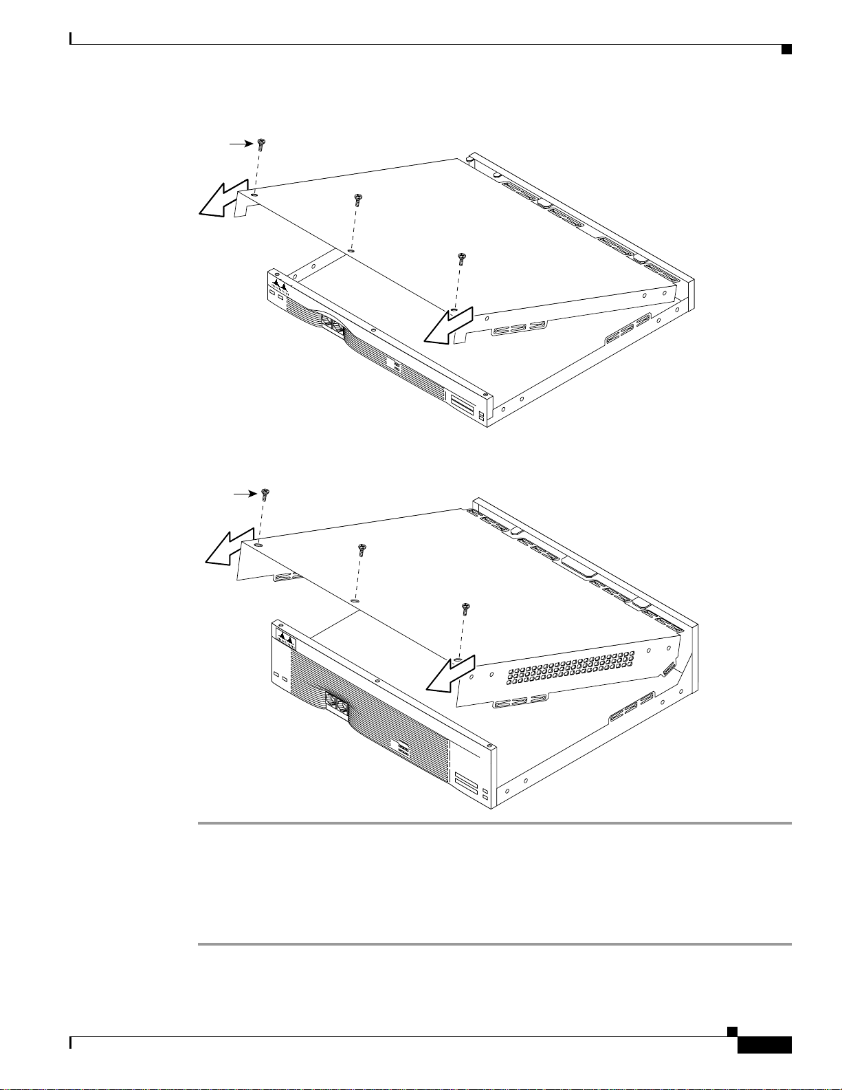
Step 3 Place the router so that the front panel is facing you. Remove the three screws located on top of the cover
near the front edge. (See Figure 5-1 or Figure 5-2.) Set the screws aside in a safe place.
Step 4 Lift the front edge of the cover until it clears the front of the chassis. (See Figure 5-1 or Figure 5-2.)
Step 5 Pull the cover toward you until the metal tabs on the rear edge separate from the chassis bottom. (See
Figure 5-1 or Figure 5-2.)
Step 6 Lift the cover until it is free from the chassis and set it aside.
When you are ready to replace the cover, see the “Replacing the Cover on a Cisco 3620 or Cisco 3640
Router” section on page 5-30.
Cisco 3600 Series Hardware Installation Guide
OL-2056-02
Page 3
Chapter 5 Installing Memory in the Router
Figure 5-1 Removing the Cisco 3620 Router Cover
Screw
Accessing the Mainboard
SYSTEM
RPS
CON
AUX
ACTIVE
0
1
READY
PCMCIA
1
0
H7241
Figure 5-2 Removing the Cisco 3640 Router Cover
Screw
SYSTEM
RPS
CON
AUX
ACTIVE
0
123
READY
1
PCMCIA
0
H7043
Removing the Cisco 3631 Router Cover
Perform the following procedure to remove the chassis cover:
Step 1 Power OFF the router. However, to channel ESD voltages to ground, do not unplug the power cable.
OL-2056-02
Cisco 3600 Series Hardware Installation Guide
5-3
Page 4
Accessing the Mainboard
Chapter 5 Installing Memory in the Router
Warning
Before opening the chassis, disconnect the telephone-network cables to avoid contact
with telephone-network voltages. To see translations of the various warnings that
appear in this publication, refer to the Regulatory Compliance and Safety Information
document that accompanied this device.
Step 2 Disconnect all network interface cables from the rear panel.
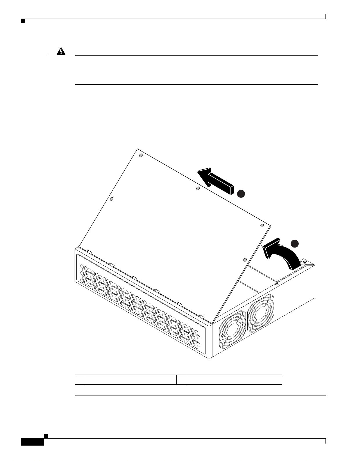
Step 3 Place the router on a flat surface. Remove the five screws located on top of the cover.
Step 4 Rotate the cover up to a 45-degree angle. (See Figure 5-3.)
Step 5 Slide the cover to the side until the tabs are free from the slots. (See Figure 5-3.)
Figure 5-3 Removing the Cisco 3631 Router Cover
2
1 Lift cover 2 Slide cover
1
62483
5-4
Cisco 3600 Series Hardware Installation Guide
OL-2056-02
Page 5
Chapter 5 Installing Memory in the Router
Removing the Cisco 3660 Mainboard Tray
Note In this publication, references to Cisco 3660 routers include both Cisco 3661 and Cisco 3662 models.
Use the following procedure to remove the mainboard tray:
Step 1 Power OFF the router. However, to channel ESD voltages to ground, do not unplug the power cable.
Accessing the Mainboard
Warning
Step 2 Remove all network interface cables from the mainboard tray’s rear panel.
Step 3 Place the router so that the rear panel is facing you.
Before opening the chassis, disconnect the telephone-network cables to avoid contact with
telephone-network voltages. To see translations of the warnings that appear in this publication,
refer to the
device.
Regulatory Compliance and Safety Information
document that accompanied this
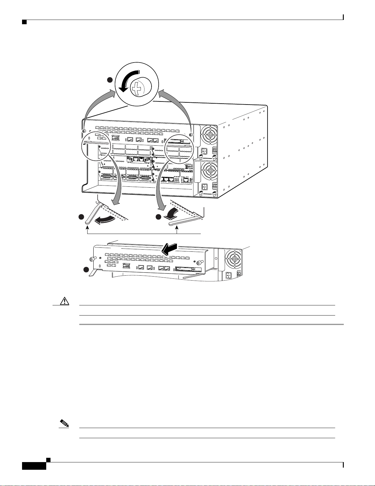
There are two sets of screws on the mainboard rear panel: one set of captive screws, and one set of Torx
screws. (See Figure 5-4.)
Caution Do not remove or loosen the Torx screws.
Step 4 Loosen the two captive screws located in the upper corners. (See part 1, Figure 5-4.)
Step 5 Swing the two tray levers out, and slide the mainboard tray out of the chassis. (See parts 2 and 3,
Figure 5-4.)
OL-2056-02
Cisco 3600 Series Hardware Installation Guide
5-5
Page 6
Replacing DRAM and SDRAM
ETH 0
ETH 3
ETHERNET
4E
ETH 2 ETH 1
123
ACT
LINK
0
CN/LP RXC
SERIAL 3 SERIAL 2
SERIAL 1 SERIAL 0
RXD TXC
TXD
CN/LP RXC RXD TXC TXD
CN/LP RXC RXD
TXC
TXD
CN/LP RXC RXD TXC TXD
EN
SERIAL
4T
VOICE
2V
V0
V1
EN
HIGH SPEED SERIAL
1HSSI
HS
TD
TC
RD
RC
LB/CN
Figure 5-4 Removing the Cisco 3660 Mainboard Tray
VCC OK
SYSTEM
Chapter 5 Installing Memory in the Router
1
FDX
LINK
100Mbps
VIC
FXS
IN USE
1
SEE MANUAL BEFORE INSTALLATION
FDX
LINK
100Mbps
1
0
IN USE
0
22
3
Caution The mainboard is an ESD-sensitive component. To avoid damage, observe all ESD precautions.
When you are ready to replace the mainboard tray,see the “Replacing the Cisco 3660 Mainboard Tray”
section on page 5-33.
Replacing DRAM and SDRAM
Cisco 3600 series routers use two types of dynamic random access memory (DRAM):
• DRAM SIMMs (Used in Cisco 3620 and Cisco 3640 Routers), page 5-7
• SDRAM DIMMs Used in the Cisco 3631 and Cisco 3660 Router, page 5-14
Tray levers
17335
Note SIMMs and DIMMs cannot be interchanged between the router models.
Cisco 3600 Series Hardware Installation Guide
5-6
OL-2056-02
Page 7

Chapter 5 Installing Memory in the Router
DRAM SIMMs (Used in Cisco 3620 and Cisco 3640 Routers)
This section describes how to upgrade DRAM single in-line memory modules (SIMMs) in Cisco 3620
and Cisco 3640 routers. You might need to upgrade the DRAM SIMMs for the following reasons:
• You upgraded the Cisco IOS feature set or release and it requires additional DRAM.
• The router maintains large routing tables or other memory-intensive features, such as spoofing or
protocol translations.
The Cisco 3620 and Cisco 3640 routers each contain four 72-pin SIMM sockets (or banks) for DRAM.
Each socket can be filled with a single 32-bit-wide, 72-pin DRAM SIMM. You can configure DRAM as
a mixture of primary or main memory, which is reserved for the CPU, and shared memory, which is used
for data transmitted or received by modules and WAN interface cards.
To see how much memory is currently installed in the router, enter the show version command while the
router is in the privileged EXEC mode (Router# prompt). Near the middle of the resulting output, a
message similar to the following displays:
Cisco 3640(R4700) processor (revision 0x00) with 24576K/8192K bytes of memory.
This line shows how much memory is installed (in this example, 24576K/8192K). The first number
represents primary memory and the second number represents shared memory.
You can configure DRAM to be either 32 or 64 bits wide. To use 64-bit mode, you must install DRAM
SIMMs in pairs of the same size. Generally, basic software feature sets (such as IP) use 32-bit DRAM
SIMMs and robust software feature sets (such as Enterprise) use 64-bit DRAM SIMMs.
Replacing DRAM and SDRAM
Note In the Cisco 3620 router, DRAM supports 32-bit operation only, whereas in the Cisco 3640 router,
DRAM supports either 32- or 64-bit operation.
Note In 32-bit mode, the router performs approximately 20 percent slowerthan when DRAM is configured
for 64-bit mode operation.
Each SIMM socket corresponds to one bank of memory. Fill banks consecutively with no gaps; start
fillingbanks from 0, and empty banks starting with 3. Bank 0 must always be filled first and emptied last.
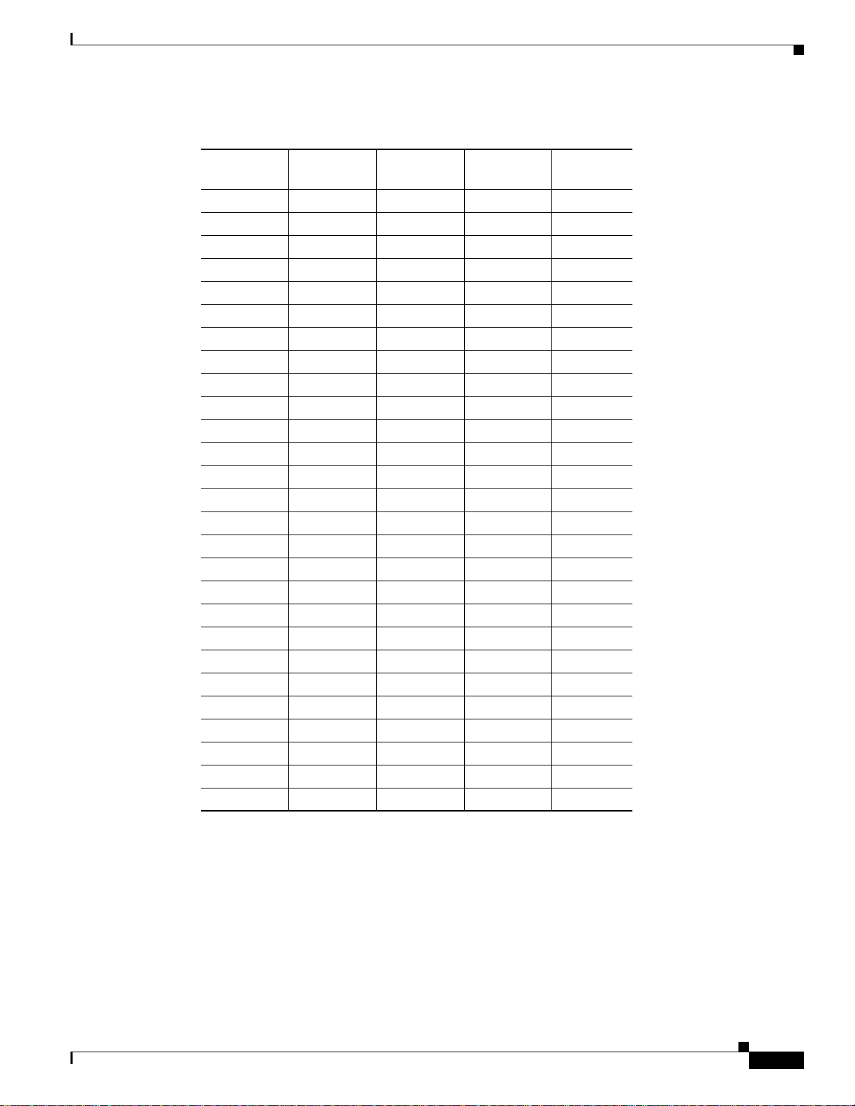
Only certain combinations of DRAM SIMMs are permitted. These combinations are shown inTable 5-1
for 32-bit configurations used in Cisco 3620 routers, Table 5-2 for 32-bit configurations used in
Cisco 3640 routers, and Table 5-3 for 64-bit configurations used in Cisco 3640 routers.
Follow these rules to use 64-bit mode DRAM configuration:
• SIMMs in banks 0 and 1 must be the same size (in MB) and have the same access time (in
nanoseconds).
• SIMMs in banks 2 and 3 must also be the same size and have the same access time.
• SIMMs in banks 2 and 3 must be less than or equal to the size of the SIMMs in banks 0 and 1.
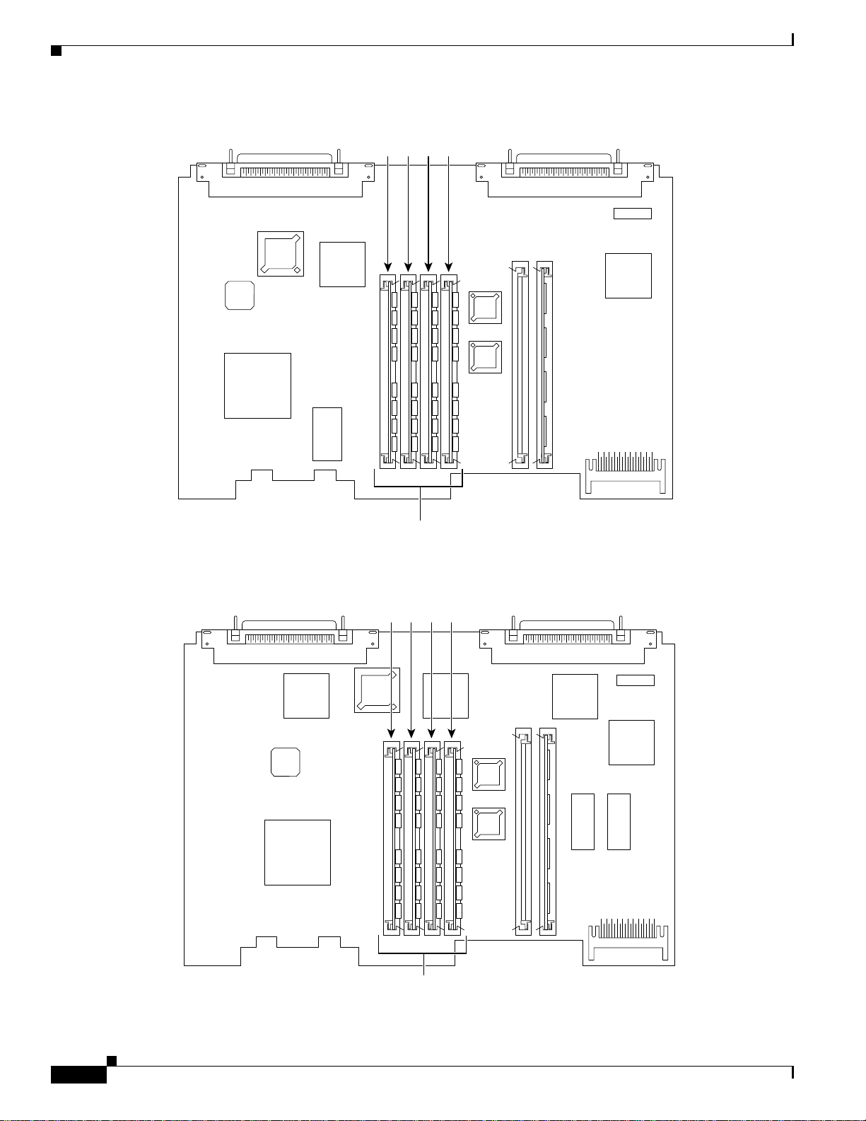
Figure 5-5 or Figure 5-6 shows the DRAM SIMM locations in your router.
OL-2056-02
Cisco 3600 Series Hardware Installation Guide
5-7
Page 8
Replacing DRAM and SDRAM
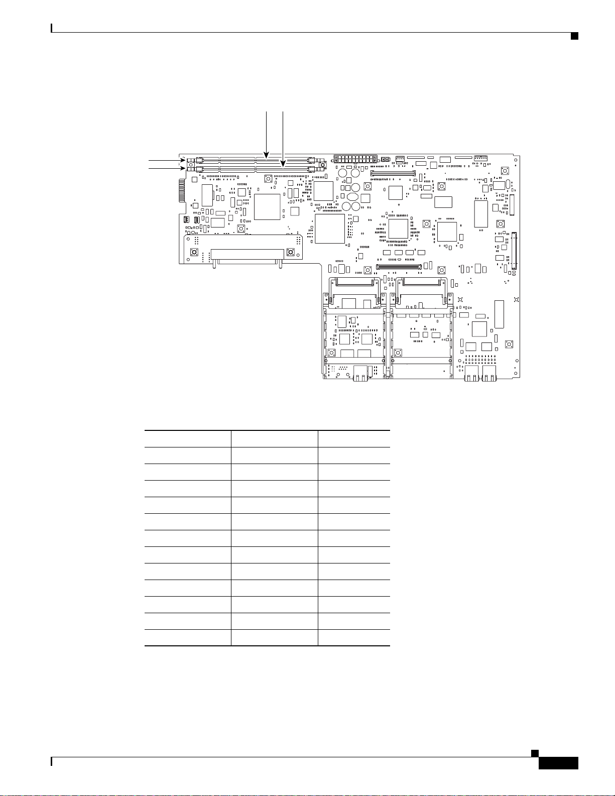
Figure 5-5 DRAM SIMM Locations in the Cisco 3620 Router
Chapter 5 Installing Memory in the Router
0123
DRAM SIMMs
Figure 5-6 DRAM SIMM Locations in the Cisco 3640 Router
0123
H7317
5-8
H7081
DRAM SIMMs
Cisco 3600 Series Hardware Installation Guide
OL-2056-02
Page 9
Chapter 5 Installing Memory in the Router
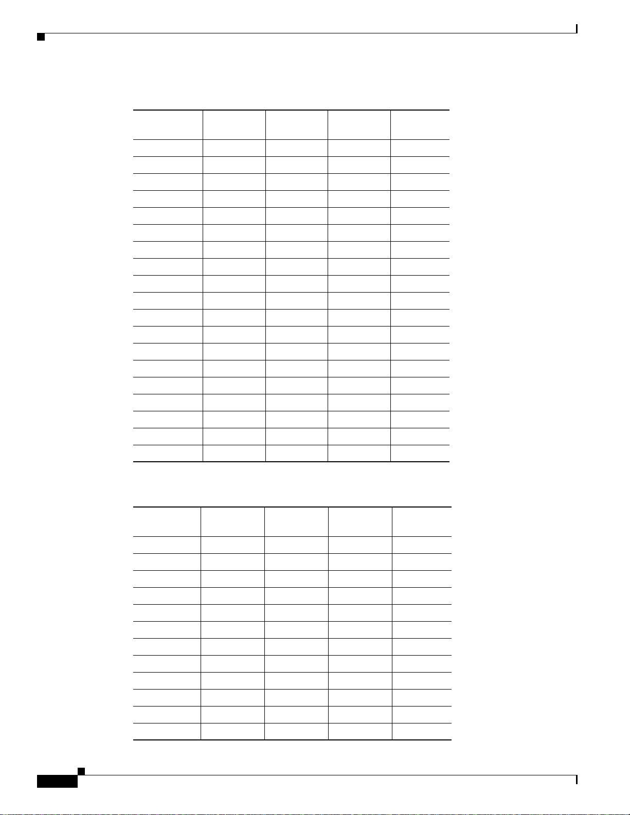
Table 5-1 32-Bit DRAM Configuration for Cisco 3620 Routers
Replacing DRAM and SDRAM
Bank 0
(SIMM 0)
Bank 1
(SIMM 1)
Bank 2
(SIMM 2)
Bank 3
(SIMM 3)
Total
Memory
4 MB 4 MB 4 MB 4 MB 16 MB
4 MB 4 MB 8 MB Not installed 16 MB
8 MB 8 MB Not installed Not installed 16 MB
16 MB Not installed Not installed Not installed 16 MB
4 MB 16 MB Not installed Not installed 20 MB
4 MB 4 MB 4 MB 4 MB 16 MB
8 MB 8 MB 4 MB Not installed 20 MB
16 MB 4 MB Not installed Not installed 20 MB
8 MB 16 MB Not installed Not installed 24 MB
8 MB 8 MB 8 MB Not installed 24 MB
8 MB 8 MB 4 MB 4 MB 24 MB
16 MB 8 MB Not installed Not installed 24 MB
8 MB 8 MB 4 MB 8 MB 28 MB
8 MB 8 MB 8 MB 4 MB 28 MB
8 MB 8 MB 16 MB Not installed 32 MB
8 MB 8 MB 8 MB 8 MB 32 MB
16 MB 16 MB Not installed Not installed 32 MB
16 MB 16 MB 4 MB Not installed 36 MB
16 MB 16 MB 4 MB 4 MB 40 MB
16 MB 16 MB 8 MB Not installed 40 MB
16 MB 16 MB 4 MB 8 MB 44 MB
16 MB 16 MB 8 MB 4 MB 44 MB
16 MB 16 MB 8 MB 8 MB 48 MB
16 MB 16 MB 16 MB Not installed 48 MB
16 MB 16 MB 16 MB 4 MB 52 MB
16 MB 16 MB 16 MB 8 MB 56 MB
16 MB 16 MB 16 MB 16 MB 64 MB
OL-2056-02
Cisco 3600 Series Hardware Installation Guide
5-9
Page 10
Replacing DRAM and SDRAM
Table 5-2 32-Bit DRAM Configuration for Cisco 3640 Routers
Chapter 5 Installing Memory in the Router
Bank 0 (SIMM0)Bank 1
(SIMM 1)
Bank 2
(SIMM 2)
Bank 3
(SIMM 3)
Total
Memory
4 MB 4 MB 8 MB Not installed 16 MB
16 MB Not installed Not installed Not installed 16 MB
4 MB 16 MB Not installed Not installed 20 MB
8 MB 8 MB 4 MB Not installed 20 MB
16 MB 4 MB Not installed Not installed 20 MB
8 MB 16 MB Not installed Not installed 24 MB
8 MB 8 MB 8 MB Not installed 24 MB
16 MB 8 MB Not installed Not installed 24 MB
8 MB 8 MB 4 MB 8 MB 28 MB
8 MB 8 MB 8 MB 4 MB 28 MB
8 MB 8 MB 16 MB Not installed 32 MB
16 MB 16 MB 4 MB Not installed 36 MB
16 MB 16 MB 8 MB Not installed 40 MB
16 MB 16 MB 8 MB 4 MB 44 MB
16 MB 16 MB 4 MB 8 MB 44 MB
16 MB 16 MB 16 MB 4 MB 52 MB
16 MB 16 MB 4 MB 16 MB 52 MB
16 MB 16 MB 16 MB 8 MB 56 MB
16 MB 16 MB 8 MB 16 MB 56 MB
5-10
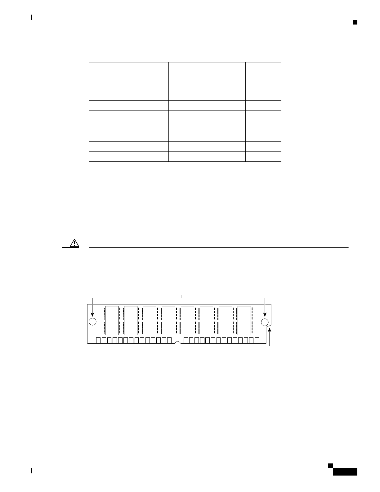
Table 5-3 64-Bit DRAM Configuration for Cisco 3640 Routers
Bank 0
(SIMM 0)
Bank 1
(SIMM 1)
4 MB 4 MB 4 MB 4 MB 16 MB
1
8 MB
8 MB Not installed Not installed 16 MB
8 MB-Dual28 MB-Dual Not installed Not installed 16 MB
8 MB 8 MB 4 MB 4 MB 24 MB
8 MB-Dual 8 MB-Dual 4 MB 4 MB 24 MB
8 MB 8 MB 8 MB 8 MB 32 MB
8 MB 8 MB 8 MB-Dual 8 MB-Dual 32 MB
8 MB-Dual 8 MB-Dual 8 MB 8 MB 32 MB
8 MB-Dual 8 MB-Dual 8 MB-Dual 8 MB-Dual 32 MB
16 MB 16 MB – – 32 MB
16 MB 16 MB 4 MB 4 MB 40 MB
16 MB 16 MB 8 MB 8 MB 48 MB
Cisco 3600 Series Hardware Installation Guide
Bank 2
(SIMM 2)
Bank 3
(SIMM 3)
Total
Memory
OL-2056-02
Page 11
Chapter 5 Installing Memory in the Router
Table 5-3 64-Bit DRAM Configuration for Cisco 3640 Routers (continued)
Replacing DRAM and SDRAM
Bank 0
(SIMM 0)
16 MB 16 MB 8 MB-Dual 8 MB-Dual 48 MB
16 MB 16 MB 16 MB 16 MB 64 MB
32 MB-Dual332 MB-Dual Not installed Not installed 64 MB
32 MB-Dual 32 MB-Dual 4 MB 4 MB 72 MB
32 MB-Dual 32 MB-Dual 8 MB 8 MB 80 MB
32 MB-Dual 32 MB-Dual 8 MB-Dual 8 MB-Dual 80 MB
32 MB-Dual 32 MB-Dual 16 MB 16 MB 96 MB
32 MB-Dual 32 MB-Dual 32 MB-Dual 32 MB-Dual 128 MB
1. 8 MB = single-bank SIMM, 8 MB in size.
2. 8 MB-Dual = dual-bank SIMM, 8 MB in size.
3. 32 MB-Dual = dual-bank SIMM, 32 MB in size.
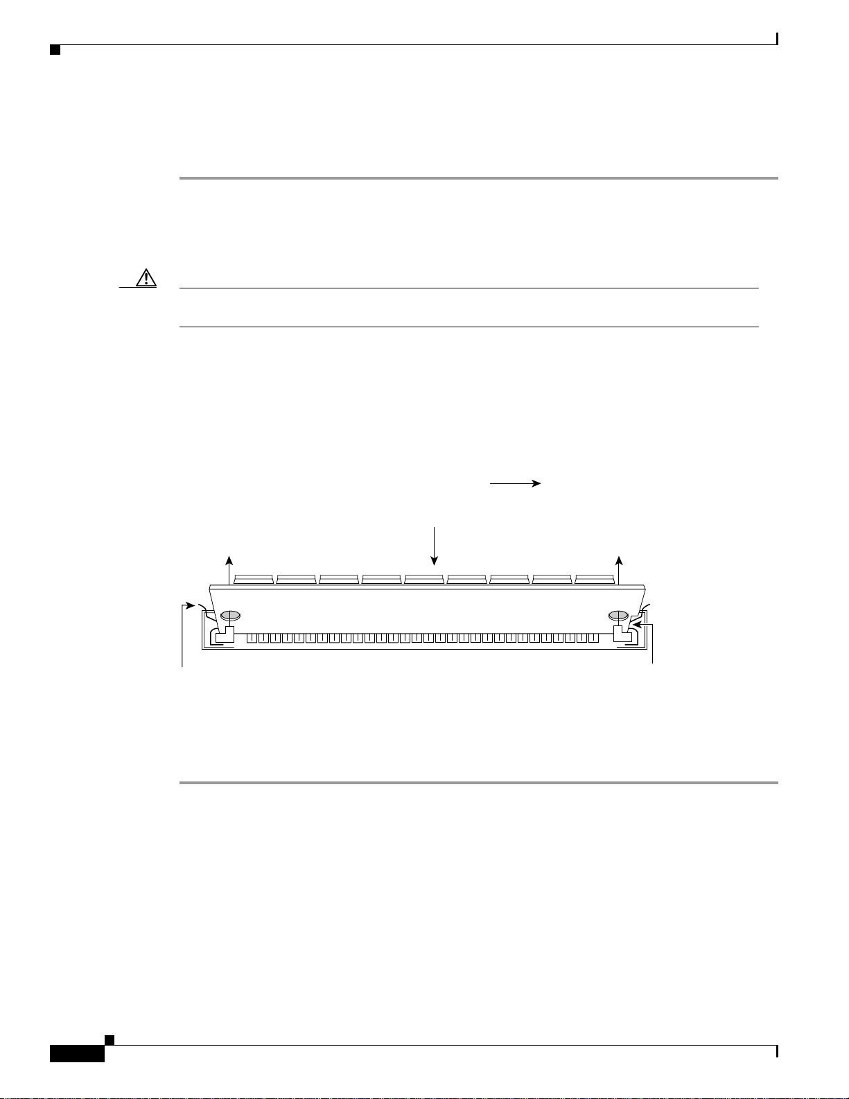
DRAM SIMM Orientation
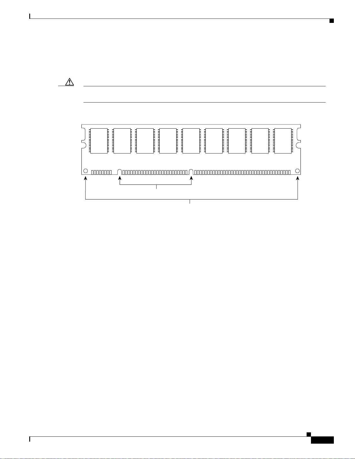
SIMMs have a polarization notch to ensure proper orientation and alignment holes to ensure proper
positioning. Figure 5-7 shows the polarization notch and alignment holes on a SIMM. DRAM SIMMs
are installed with the connector edge down and the polarization notch near the front of the chassis.
Bank 1
(SIMM 1)
Bank 2
(SIMM 2)
Bank 3
(SIMM 3)
Total
Memory
Caution To avoid damaging ESD-sensitive components, observe all ESD precautions. To avoid damaging the
underlying mainboard, do not use excessive force when you remove or replace SIMMs.
Figure 5-7 DRAM SIMM
Alignment holes
H2407
Connector edge
Polarization notch
OL-2056-02
Cisco 3600 Series Hardware Installation Guide
5-11
Page 12
Replacing DRAM and SDRAM
Removing DRAM SIMMS
Perform this procedure to remove DRAM SIMMs:
Step 1 Attach an ESD-preventive wrist strap and ensure that it makes good contact with your skin. Connect the
equipment end of the wrist strap to the metal back plate of the chassis, avoiding contact with the
connectors.
Step 2 On the mainboard, locate the DRAM SIMM sockets shown in Figure 5-5 or Figure 5-6.
Caution Handle SIMMs by the non-connector edges only. SIMMs are ESD-sensitive components and can be
damaged by mishandling.
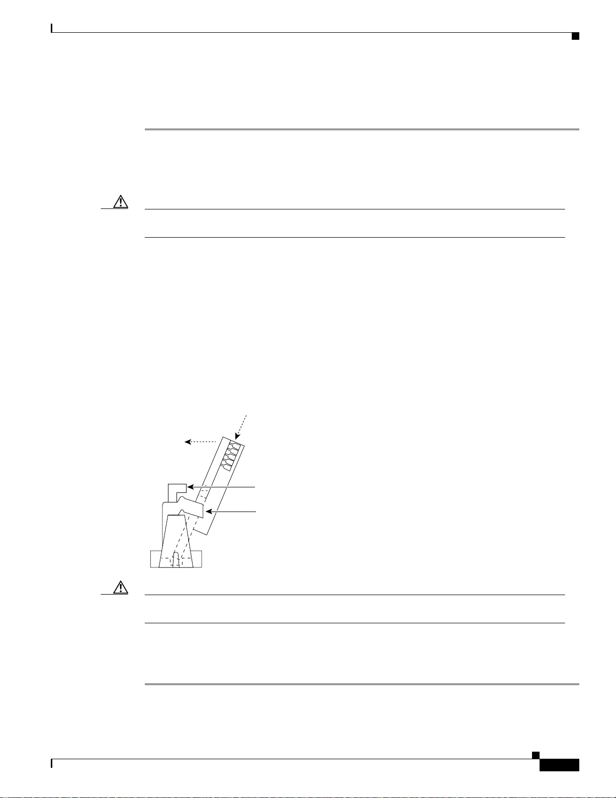
Step 3 Remove one SIMM at a time, beginning with the SIMM in bank 3. To lift the SIMM out of its socket,
pull the locking spring clips on both sides outward and tilt the SIMM toward the right side of the chassis,
until it is free of the clips. (See Figure 5-8.)
Figure 5-8 Removing DRAM SIMMs
Chapter 5 Installing Memory in the Router
Top view
Front of chassis
2. Push the top of the
SIMM forward and down.
1. Pull the locking spring clips outward.
Step 4 Hold the SIMM by the edges with your thumb and index finger and lift it out of the socket. Place the
SIMM
polarization
notch
H7038
removed SIMM in an antistatic bag to protect it from ESD damage.
Step 5 Repeat Step 3 and Step 4 for each SIMM.
5-12
Cisco 3600 Series Hardware Installation Guide
OL-2056-02
Page 13
Chapter 5 Installing Memory in the Router
Installing DRAM SIMMs
Perform this procedure to install DRAM SIMMs:
Step 1 Attach an ESD-preventive wrist strap and ensure that it makes good contact with your skin. Connect the
equipment end of the wrist strap to the metal back plate of the chassis, avoiding contact with the
connectors.
Step 2 On the mainboard, locate the DRAM SIMM sockets shown in Figure 5-5 or Figure 5-6.
Caution Handle SIMMs by the edges only. SIMMs are ESD-sensitive components and can be damaged by
mishandling.
Step 3 Hold the SIMM with the polarization notch on the right, near the front of the chassis, and with the
connector edge at the bottom.
Step 4 Beginning with bank 0, insert the SIMM into the socket at an angle, tilted toward the right side of the
chassis. Rock the SIMM into a vertical position (see Figure 5-9), using the minimum amount of force
required. When the SIMM is properly seated, the socket guide posts fit through thealignment holes, and
the locking spring clips click into place.
Step 5 Ensure that each SIMM is straight (perpendicular to the socket), and that the alignment holes (as shown
in Figure 5-9) line up with the plastic socket guides on the socket.
Replacing DRAM and SDRAM
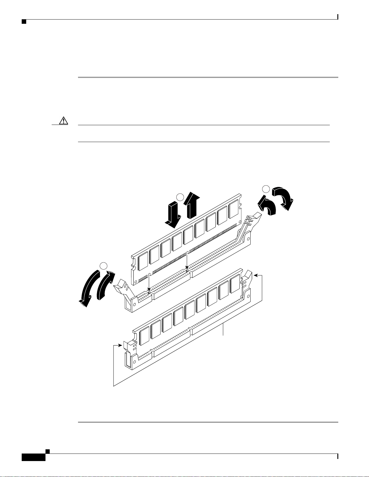
Figure 5-9 Installing DRAM SIMMs
View from front of chassis
1. Insert the SIMM into the socket
at an angle from vertical.
2. Push the top of the SIMM
down and back.
The socket guide posts fit through
3.
the holes in the SIMM.
The locking springs clip the back
4.
of the SIMM.
H7037
Caution It is normal to feel some resistance when installing a SIMM, but do not use excessive force on the
SIMM, and do not touch the surface components.
Step 6 Repeat Step 3 through Step 5 for each SIMM.
When you finish replacing SIMMs, proceed to the “Replacing the Cover on a Cisco 3620 or Cisco 3640
Router” section on page 5-30.
OL-2056-02
Cisco 3600 Series Hardware Installation Guide
5-13
Page 14

Chapter 5 Installing Memory in the Router
Replacing DRAM and SDRAM
SDRAM DIMMs Used in the Cisco 3631 and Cisco 3660 Router
This section describes how to upgrade synchronous dynamic random access memory (SDRAM) dual
in-line memory modules (DIMMs) in the Cisco 3631and Cisco 3660routers. You might need to upgrade
the SDRAM DIMMs for the following reasons:
• You upgraded the Cisco IOS feature set or release and it requires additional SDRAM.
• The router maintains large routing tables or other memory-intensive features, such as spoofing or
protocol translations.
The Cisco 3631 and Cisco 3660 routers contain two 168-pin DIMM sockets for SDRAM. Each socket
can be filled with a single 64-bit-wide, 168-pin SDRAM DIMM. You can configure SDRAM as a
mixture main memory, which is reserved for the CPU, and shared memory, which is used for data
transmitted or received by modules and WAN interface cards. See Figure 5-10 and Figure 5-11 for
DIMM locations.
To see how much memory is currently installed in the router, enter the show version command while the
router is in the privileged EXEC mode (Router# prompt). Near the middle of the resulting output, a
message similar to the following displays:
Cisco 3660(R527x) processor (revision 0x00) with 24576K/8192K bytes of memory.
This line shows how much memory is installed (in this example, 24576K/8192K). The first number
represents primary memory and the second number represents shared memory. Your router supports up
to 256 MB of SDRAM.
Each DIMM socket corresponds to one bank of memory. Fill banks from 0, and empty banks starting
with 1. Bank 0 must always be filled first and emptied last.
The Cisco 3631 router supports both parity and non-parity PC-100 DIMMs ranging in capacity from
64 MB to 128 MB. Only certain combinations of SDRAM DIMMs are permitted. (See Table 5-5.)
The Cisco 3660 router supports both parity and non-parity PC-100 DIMMs ranging in capacity from
16 MB to 128 MB. Only certain combinations of SDRAM DIMMs are permitted. (See Table 5-5.)
Note An advantage of parity DIMMs over non-parity DIMMs is easier identification of memory errors; a
disadvantage is lower processing speed.
Note To use a 64-bit mode SDRAM configuration, the DIMM in bank 1 must be less than or equal to the
size of the DIMM in bank 0.
5-14
Cisco 3600 Series Hardware Installation Guide
OL-2056-02
Page 15
Chapter 5 Installing Memory in the Router
Figure 5-10 SDRAM DIMM Locations in the Cisco 3631 Router
0
1
Replacing DRAM and SDRAM
SDRAM DIMMs
Table 5-4 SDRAM Configurations for Cisco 3631 Routers
Bank 0 (SIMM 0) Bank 1 (SIMM 1) Total Memory
64 MB Not installed 64 MB
32 MB 32 MB 64 MB
32 MB 64 MB 96 MB
64 MB 32 MB 96 MB
128 MB Not installed 128 MB
64 MB 64 MB 128 MB
Not installed 128 MB 128 MB
32 MB 128 MB 160 MB
128 MB 32 MB 160 MB
64 MB 128 MB 192 MB
128 MB 64 MB 192 MB
128 MB 128 MB 256 MB
62578
OL-2056-02
Cisco 3600 Series Hardware Installation Guide
5-15
Page 16
Replacing DRAM and SDRAM
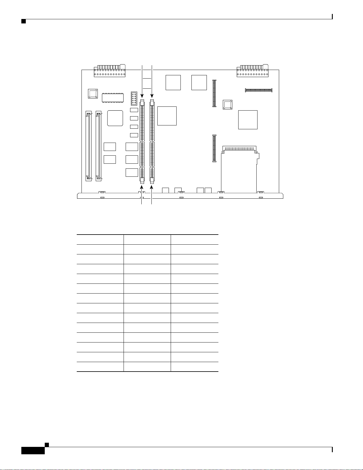
Figure 5-11 SDRAM DIMM Locations in the Cisco 3660 Router
Chapter 5 Installing Memory in the Router
SDRAM DIMMs
10
Table 5-5 SDRAM Configurations for Cisco 3660 Routers
Bank 0 (SIMM 0) Bank 1 (SIMM 1) Total Memory
16 MB 16 MB 32 MB
32 MB Not installed 32 MB
32 MB 16 MB 48 MB
32 MB 32 MB 64 MB
64 MB Not installed 64 MB
64 MB 16 MB 80 MB
64 MB 32 MB 96 MB
64 MB 64 MB 128 MB
128 MB Not installed 128 MB
128 MB 16 MB 144 MB
128 MB 32 MB 160 MB
128 MB 64 MB 192 MB
128 MB 128 MB 256 MB
17337
5-16
Cisco 3600 Series Hardware Installation Guide
OL-2056-02
Page 17
Chapter 5 Installing Memory in the Router
SDRAM DIMM Orientation
DIMMs have polarization notches to ensure proper orientation and alignment holes to ensure proper
positioning. Figure 5-12 shows the polarization notches and alignment holes on a DIMM.
Caution To avoid damaging ESD-sensitive components, observe all ESD precautions. To avoid damaging the
underlying mainboard, do not use excessive force when you remove or replace DIMMs.
Figure 5-12 SDRAM DIMM
Replacing DRAM and SDRAM
17338
Connector edge
Polarization notches
Alignment holes
OL-2056-02
Cisco 3600 Series Hardware Installation Guide
5-17
Page 18
Replacing DRAM and SDRAM
Removing SDRAM DIMMS
Perform this procedure to remove SDRAM DIMMs:
Step 1 Attach an ESD-preventive wrist strap and ensure that it makes good contact with your skin. Connect the
equipment end of the wrist strap to the metal back plate of the chassis, avoiding contact with the
connectors.
Step 2 On the mainboard, locate the SDRAM DIMM sockets shown in Figure 5-11.
Caution Handle DIMMs by the edges only. DIMMs are ESD-sensitive components and can be damaged by
mishandling.
Step 3 Remove the DIMM by pushing the locking spring clips on both sides outward. This ejects the DIMM
from its socket. (See Figure 5-13.)
Figure 5-13 Removing and Installing SDRAM DIMMs
Chapter 5 Installing Memory in the Router
2
1
2
17943
Locking spring clips
Step 4 Hold the DIMM by the edges with your thumb and index finger and lift it out of the socket. Place the
removed DIMM in an antistatic bag to protect it from ESD damage.
Step 5 If necessary, repeat Step 3 and Step 4 for the other DIMM.
5-18
Cisco 3600 Series Hardware Installation Guide
OL-2056-02
Page 19

Chapter 5 Installing Memory in the Router
Installing SDRAM DIMMs
Perform this procedure to install SDRAM DIMMs:
Step 1 Attach an ESD-preventive wrist strap and ensure that it makes good contact with your skin. Connect the
equipment end of the wrist strap to the metal back plate of the chassis, avoiding contact with the
connectors.
Step 2 On the mainboard, locate the SDRAM DIMM sockets shown in Figure 5-11.
Caution Handle DIMMs by the non-connector edges only. DIMMs are ESD-sensitive components and can be
damaged by mishandling.
Step 3 Hold the DIMM with the polarization notch on the right, near the rear of the chassis, and with the
connector edge at the bottom.
Step 4 Beginning with socket 0, insert the DIMM perpendicular to the socket. Push firmly into place (see
Figure 5-13), using the minimum amount of force required. When the DIMM is properly seated, the
socket guide posts fit through the alignment holes, and the locking spring clips click into place.
Step 5 Ensure that each DIMM is straight (perpendicular to the socket). (See Figure 5-13.)
Replacing Flash Memory SIMMs
Caution It is normal to feel some resistance when installing a DIMM, but do not use excessive force on the
DIMM, and do not touch the surface components.
Step 6 Repeat Step 3 through Step 5 for each DIMM.
When you finish replacing DIMMs, and have installed all internal components, proceed to the
“Replacing the Cisco 3660 Mainboard Tray” section on page 5-33.
Replacing Flash Memory SIMMs
This section describes how to upgrade the Flash memory SIMMs. The system code (Cisco IOS software)
is stored in the Flash memory SIMMs. You might need to replace or add Flash memory SIMMs to
upgrade to a new Cisco IOS software feature set.
The router contains one or two 80-pin Flash memory SIMMs. You can upgrade Flash memory by
replacing the existing 4-MB SIMM with an 8- or 16-MB SIMM, or by adding a SIMM to the second
Flash memory socket. You can install from 4 to 32 MB of Flash memory. The size of the SIMMs in the
two Flash memory sockets need not be the same.
Note Flash memory SIMMs are not interchangeable with DRAM SIMMs (used in Cisco 3620 and
Cisco 3640 routers) or SDRAM DIMMs (used in Cisco 3631 and Cisco 3660 routers).
OL-2056-02
Each Flash memory SIMM socket corresponds to one bank of memory. Fill banks starting with 0, and
empty banks starting with 1. Bank 0 must always be filled first and emptied last.
Table 5-6 lists possible Flash memory SIMM configurations and the resulting total Flash memory.
Cisco 3600 Series Hardware Installation Guide
5-19
Page 20

Replacing Flash Memory SIMMs
Table 5-6 Flash Memory SIMM Configurations
Bank 0 Bank 1 Total Memory
4 MB – 4 MB
4 MB 4 MB 8 MB
4 MB 8 MB 12 MB
4 MB 16 MB 20 MB
8 MB – 8 MB
8 MB 4 MB 12 MB
8 MB 8 MB 16 MB
8 MB 16 MB 24 MB
16 MB – 16 MB
16 MB 4 MB 20 MB
16 MB 8 MB 24 MB
16 MB 16 MB 32 MB
32 MB 32 MB 64 MB
1. The 64 MB configuration is only available on the
Cisco 3660 router.
Chapter 5 Installing Memory in the Router
1
Flash memory SIMMs have a polarization notch to ensure proper orientation and alignment holes to
ensure proper positioning, similar to that shown in Figure 5-7. Flash memory SIMMs are installed with
the connector edge down and the polarization notch near the front of the chassis.
Caution To avoid damaging ESD-sensitive components, observe all ESD precautions. To avoid damaging the
underlying mainboard, do not use excessive force when you remove or replace SIMMs.
Figure 5-14, Figure 5-15, and Figure 5-16 show the location of the Flash memory SIMMs on your
router’s mainboard.
5-20
Cisco 3600 Series Hardware Installation Guide
OL-2056-02
Page 21

Chapter 5 Installing Memory in the Router
Figure 5-14 Flash Memory SIMM Locations on the Cisco 3620 Mainboard
Replacing Flash Memory SIMMs
10
Flash memory SIMMs
Figure 5-15 Flash Memory SIMM Locations on the Cisco 3640 Mainboard
10
H7318
OL-2056-02
Flash memory SIMMs
H7082
Cisco 3600 Series Hardware Installation Guide
5-21
Page 22

Replacing Flash Memory SIMMs
Figure 5-16 Flash Memory SIMM Locations on the Cisco 3660 Mainboard
Flash memory SIMMs
Chapter 5 Installing Memory in the Router
10
Removing Flash Memory SIMMs
Perform this procedure to remove a Flash memory SIMM from a mainboard:
Step 1 Attach an ESD-preventive wrist strap and ensure that it makes good contact with your skin. Connect the
equipment end of the wrist strap to the metal back plate of the chassis, avoiding contact with the
connectors.
Step 2 Locate the Flash memory SIMM sockets on the mainboard. (See Figure 5-14 through Figure 5-16.)
Caution Handle SIMMs by the non-connector edges only. SIMMs are ESD-sensitive components and can be
damaged by mishandling.
Step 3 To lift the Flash memory SIMM out of its socket, pull the locking spring clips onboth sides outward and
tilt the SIMM toward the left side of the chassis, free of the clips. (See Figure 5-17.)
17340
5-22
Cisco 3600 Series Hardware Installation Guide
OL-2056-02
Page 23

Chapter 5 Installing Memory in the Router
Figure 5-17 Removing Flash Memory SIMMs
Replacing Flash Memory SIMMs
Top view
SIMM polarization notch
1. Pull the locking spring clips outward.
2. Push the top of the SIMM
forward and down.
Front of chassis
H7085
Installing Flash Memory SIMMs
Perform this procedure to install Flash memory SIMMs:
Step 1 Locate the Flash memory SIMM sockets on the mainboard. (See Figure 5-14 through Figure 5-16.)
Caution Handle SIMMs by the non-connector edges only. SIMMs are ESD-sensitive components and can be
damaged by mishandling.
Step 2 Hold the SIMM with the polarization notch on the right and the component side away from you, with
the connector edge at the bottom.
Step 3 Beginning with bank 0, insert the Flash memory SIMM into its connector slot at an angle, tilted toward
the left side of the chassis. (See Figure 5-18.) Rock the SIMM into a vertical position using the minimum
amount of force required. When the SIMM is properly seated, the socketguide posts fit in the alignment
holes, and the locking springs click into place. Use a minimum of force.
OL-2056-02
Cisco 3600 Series Hardware Installation Guide
5-23
Page 24

Replacing the ROM
Caution It is normal to feel some resistance, but do not use excessive force on the SIMM and do not touch the
Figure 5-18 Inserting Flash Memory SIMMs
View from front of chassis
1. Insert the SIMM into the socket
at an angle from vertical.
2. Push the top of the SIMM
down and back.
The socket guide posts fit through
3.
the holes in the SIMM.
The locking springs clip the back
4.
of the SIMM.
H7084
surface components to avoid damaging them.
Chapter 5 Installing Memory in the Router
Step 4 Check the alignment of each SIMM to make sure that it is straight and that the alignment holes are lined
up with the plastic socket guides.
Step 5 When you finish replacing Flash memory SIMMs, and have installed all internal components, proceed
to either of these sections:
• Replacing the Cover on a Cisco 3620 or Cisco 3640 Router, page 5-30
• Replacing the Cisco 3660 Mainboard Tray, page 5-33
Replacing the ROM
Cisco 3620, Cisco 3640, and Cisco3660
To upgrade the router ROM software to a new ROM monitor version, you must replace the existing
ROM.
You will need the following tools:
• ROM extraction tool or a small flat-blade screwdriver
• Needlenose pliers
• One 32-pin plastic leaded chip carrier (PLCC) for removing the ROM chip from the Cisco 3660
mainboard
5-24
Cisco 3600 Series Hardware Installation Guide
OL-2056-02
Page 25

Chapter 5 Installing Memory in the Router
Follow this procedure to replace the ROM:
Step 1 Attach an ESD-preventive wrist strap and ensure that it makes good contact with your skin. Connect the
equipment end of the wrist strap to the metal backplane of the chassis, avoiding contact with the
connectors.
Step 2 Access the mainboard by following the procedures in one of the following sections:
• Removing the Cisco 3620 or Cisco 3640 Router Cover, page 5-2
• Removing the Cisco 3660 Mainboard Tray, page 5-5
Caution Correct placement of the ROM is crucial. If improperly positioned, the new component could be
damaged when the router is powered on. Read all instructions before proceeding. To prevent damage
to the ROM from ESD (when handling the router and its components), follow the ESD procedures
described in the “Preventing Electrostatic Discharge Damage” section on page 2-2. Be careful not to
damage or scratch the printed circuit card under the ROM.
Step 3 Locate the ROM on the mainboard. (See Figure 5-19 through Figure 5-21.)
Replacing the ROM
Figure 5-19 ROM Location on the Cisco 3620 Mainboard
ROM
H7319
OL-2056-02
Cisco 3600 Series Hardware Installation Guide
5-25
Page 26

Replacing the ROM
Chapter 5 Installing Memory in the Router
Figure 5-20 ROM Location on the Cisco 3640 Mainboard
ROM
Figure 5-21 ROM Location on the Cisco 3660 Mainboard
ROM
H7083
5-26
17341
Step 4 If you have a Cisco 3620 or Cisco 3640 router, gently remove the old ROM with a ROM extraction tool
or a small flat-blade screwdriver, and set it aside.
If you have a Cisco 3660 router, gently remove the old ROM with a 32-pin PLCC extractor, and set it
aside. (See Figure 5-22.)
Cisco 3600 Series Hardware Installation Guide
OL-2056-02
Page 27

Chapter 5 Installing Memory in the Router
Figure 5-22 Removing the ROM from the Cisco 3660 Mainboard
Angled tips
Replacing the ROM
PLCC extraction
tool
Extraction slots
extraction slot
PLCC
extraction slot
PLCC
ROM
ROM socket
14624
Step 5 Fora Cisco 3620 or Cisco 3640 router,orient and insert the new ROM in its socket (shownin Figure 5-19
and Figure 5-20), being careful to not bend or crush any of the bottom pins. To straighten out a bent pin,
use needlenose pliers. Align the notch in the new ROM with the notch in the ROM socket, ignoring the
orientation of the label.
For a Cisco 3660 router, orient and insert the new ROM in its socket as shown in Figure 5-23, being
careful to not bend or crush any of the bottom pins. To straighten out a bent pin, use needlenose pliers.
Align the notch in the new ROM with the notch in the ROM socket, ignoring the orientation of the label.
Figure 5-23 Installing the ROM in the Cisco 3660 Mainboard
Press the
ROM into
place evenly
Align notches
on ROM
and socket
and firmly
OL-2056-02
14063
Cisco 3600 Series Hardware Installation Guide
5-27
Page 28

Replacing the ROM
Caution The notch on the ROM must match the notch onthe mainboard socket. Installing the ROM backward
will damage the ROM, the router, or both.
When you finish replacing the ROM and have installed all internal components, proceed to:
• Replacing the Cover on a Cisco 3620 or Cisco 3640 Router, page 5-30
• Replacing the Cisco 3660 Mainboard Tray, page 5-33
Testing ROM Installation
Test your installation by rebooting the router. If you installed the ROM correctly, the router will boot
into the ROM monitor or the Cisco IOS software.
If you suspect that the ROM is inserted incorrectly, remove and reinstall the ROM as described in the
“Replacing the ROM” section on page 5-24. Reboot the router again.
If you are still having problems after following the steps in this procedure, refer to Appendix A,
“Troubleshooting.”
Chapter 5 Installing Memory in the Router
Cisco 3631
Step 1 Copy the ROM image from the TFTP server:
The boot flash device on the Cisco 3631 router is a 1 MB, fixed flash device that is not field-replaceable.
The ROM image can be upgraded by downloading new software. The first image in ROM is read-only
and cannot be erased and the upgrade image is a read-write image that is stored in ROM flash as the
second image. You can configure the router to boot from either image.
In order to upgrade the ROM on the Cisco 3631, you will need to have a ROM image file available to
copy from a remote server or internal flash memory.
Perform this procedure to upgrade the Cisco 3631 ROM from a TFTP server:
Router # upgrade rom-monitor file tftp://172.19.169.99/rommon_file.srec
Loading rommon_file.srec from 172.19.169.99 (via FastEthernet0/0):
!!!!!!!!!!!!!!!!!!!!!!!!!!!!!!!!!!!!!!!!!!!!!!!!!!!!!!!!!!!!!!!!!!!!!!!!!!!!!!!!!!!!!!!!!!
!!!!!!!!!!!!!!!!!!!!!!!!!!!!!!!!!!!!!!
[OK - 651041/1301504 bytes]
Router #
This command will reload the router. Continue? [yes/no]: y
ROMMON image upgrade in progress
Erasing boot flash eeeeeeeeeeeeeeeeeeeeeeeeeeeeeeeeeeeeeeeeee
Programming boot flash pppp
Now Reloading
System Bootstrap, Version 12.2(4r)XT1, RELEASE SOFTWARE (fc1)
TAC Support: http://www.cisco.com/tac
Copyright (c) 2001 by cisco Systems, Inc.
5-28
Running new upgrade for first time
System Bootstrap, Version 12.2(4r)XT1, RELEASE SOFTWARE (fc1)
TAC Support: http://www.cisco.com/tac
Cisco 3600 Series Hardware Installation Guide
OL-2056-02
Page 29

Chapter 5 Installing Memory in the Router
Copyright (c) 2001 by cisco Systems, Inc.
c3745 processor with 131072 Kbytes of main memory
Main memory is configured to 64 bit mode with parity disabled
Upgrade ROMMON initialized
Step 2 Reboot the router using the new ROM image:
Router # reload
This command will reload the router. Continue? [yes/no]: y
Step 3 Verify the ROM version:
Router # show rom-monitor
ReadOnly ROMMON version:
System Bootstrap, Version 12.2(4r)XT1, RELEASE SOFTWARE (fc1)
TAC Support: http://www.cisco.com/tac
Copyright (c) 2001 by cisco Systems, Inc.
Upgrade ROMMON version:
System Bootstrap, Version 12.2(4r)XT1, RELEASE SOFTWARE (fc1)
TAC Support: http://www.cisco.com/tac
Copyright (c) 2001 by cisco Systems, Inc.
Closing the Router
Currently running ROMMON from Upgrade region
ROMMON from Upgrade region is selected for next boot
Step 4 Select the ROM image for next reboot:
Router # upgrade rom-monitor preference [readonly | upgrade]
You are about to mark Upgrade region of ROMMON for the highest boot preference.
Proceed? [confirm] y
Done! Router must be reloaded for this to take affect.
Closing the Router
Caution Before closing the router make sure that all cables are securely tucked in and are not in danger of
being pinched or cut.
OL-2056-02
Cisco 3600 Series Hardware Installation Guide
5-29
Page 30

Chapter 5 Installing Memory in the Router
Closing the Router
Replacing the Cover on a Cisco 3620 or Cisco 3640 Router
This section describes how to replace the router cover. You need a number 2 Phillips screwdriver to
perform this procedure:
Step 1 Place the chassis so the front panel faces you.
Step 2 Hold the cover so the tabs at the rear of the cover are aligned with the chassis bottom. (See Figure 5-24
or Figure 5-25.)
Figure 5-24 Replacing the Cisco 3620 Router Cover
Chassis cover
Cover
tabs
Cover
tabs
SYSTEM
RPS
CON
AUX
ACTIVE
0
1
READY
Front panel
PCMCIA
1
0
Figure 5-25 Replacing the Cisco 3640 Router Cover
Chassis cover
Cover
tabs
Chassis
tabs
H7243
Chassis bottom
Chassis
tabs
5-30
SYSTEM
RPS
CON
AUX
Front panel
Cisco 3600 Series Hardware Installation Guide
Cover tabs
H7044
ACTIVE
0
123
READY
Side tabs
1
PCMCIA
0
Chassis bottom
OL-2056-02
Page 31

Chapter 5 Installing Memory in the Router
Step 3 Push the cover toward the rear, making sure that the cover tabs fit under the chassis back panel, and the
back panel tabs fit under the top cover.
Step 4 Lower the front of the cover onto the chassis, making sure that the side tabs on the cover fit inside the
chassis side panels, and the chassis tabs fit under the cover side panels.
Step 5 Fasten the cover with the three screws you set aside in Step 3 of the “Removing the Cisco 3620 or Cisco
3640 Router Cover” section on page 5-2.
Step 6 Reinstall the chassis on a rack, wall, or desktop.
Step 7 Reinstall network interface cables.
Step 8 Power ON the router.
Closing the Router
Warning
After wiring the DC power supply, remove the tape from the circuit breaker switch handle and
reinstate power by moving thehandle of the circuit breaker to the ON position. To see translations
of the warnings that appear in this publication, refer to the
Information
document that accompanied this device.
Replacing the Cover on a Cisco 3631 Router
Caution Before reinstalling the coveron the router, make sure that all cables are securely tucked in
and are not in danger of being pinched or cut.
Step 1 Place the chassis on a flat surface.
Step 2 Hold the cover at a 45-degree angle, and insert the tabs into the slots along the front (bezel) edge of the
chassis. (See Figure 5-26.)
Step 3 Center the cover over the chassis and lower it onto the chassis.
Regulatory Compliance and Safety
OL-2056-02
Cisco 3600 Series Hardware Installation Guide
5-31
Page 32

Closing the Router
Chapter 5 Installing Memory in the Router
Figure 5-26 Replacing the Cisco 3631 Router Cover
1
2
1 Insert tabs and slide cover 2 Close cover
Step 4 Reinstall the cover screws.
Step 5 Reinstall the chassis on a rack or desktop.
Step 6 Reconnect network interface cables.
Step 7 Power ON the router.
Warning
After wiring the DC power supply, remove the tape from the circuit breaker switch
handle and reinstate power by moving the handle of the circuit breaker to the ON
position.Tosee translations of thevarious warningsthat appearin this publication, refer
to the Regulatory Compliance and Safety Information document that accompanied this
device.
62491
5-32
Cisco 3600 Series Hardware Installation Guide
OL-2056-02
Page 33

Chapter 5 Installing Memory in the Router
Replacing the Cisco 3660 Mainboard Tray
This section describes how to replace the mainboard tray. You need a number 2 Phillips screwdriver to
perform this procedure:
Step 1 Place the chassis so the rear panel faces you.
Step 2 Hold the tray so that the tabs at the tray’s lower corners are aligned with the ledge in the chassis opening.
(See part 1 of Figure 5-27.)
Figure 5-27 Replacing the Cisco 3660 Mainboard Tray
1
Closing the Router
2
3
4
Step 3 Slide the mainboard tray into the chassis until firm contact is made with the backplane. (See part 2 in
17336
Figure 5-27.)
Step 4 Push the levers at the lower corners of the mainboard inward. (See part 3 in Figure 5-27.)
OL-2056-02
Cisco 3600 Series Hardware Installation Guide
5-33
Page 34

Chapter 5 Installing Memory in the Router
Installing and Configuring Flash Memory Cards in Cisco 3620, Cisco 3640, and Cisco 3660 Routers
Step 5 Tighten the two captive screws previously loosened in Step 3 of the “Removing the Cisco 3660
Mainboard Tray” section on page 5-5. (See part 4 in Figure 5-27.)
Step 6 Reinstall the chassis on a rack or desktop.
Step 7 Reconnect network interface cables.
Step 8 Power ON the router.
If the router does not power on, see Appendix A, “Troubleshooting.”
Installing and Configuring Flash Memory Cards in Cisco 3620,
Cisco 3640, and Cisco 3660 Routers
This section describes how to install Flash memory cards in the Cisco 3620, Cisco 3640, and Cisco 3660
routers and includes selected configuration examples for common procedures. For further configuration
information, refer to the Cisco IOS configuration guides and command references.
This section includes the following subsections:
• Installing a Flash Memory Card, page 5-34
• Removing a Flash Memory Card, page 5-37
• Partitioning a Flash Memory Card, page 5-38
• Displaying the Contents of a Flash Memory Card, page 5-39
• Copying a File from System Flash Memory to a Flash Memory Card, page 5-39
• Copying a Running Configuration File to a Flash Memory Card, page 5-40
• Copying a File from a Flash Memory Card to System Flash Memory, page 5-41
• Copying a File Between Slots, page 5-41
• Booting from a Flash Memory Card, page 5-42
• Erasing the Contents of a Flash Memory Card, page 5-43
Caution Before starting any procedures in this section, follow the ESD guidelines described in the
“Preventing Electrostatic Discharge Damage” section on page 2-2.
Installing a Flash Memory Card
The router includes two Personal Computer Memory Card International Association (PCMCIA) slots.
You can install 4-MB, 8-MB, or 16-MB Flash memory cards in these slots.
Note The PCMCIA slots are also compatible with Cisco 1000 series fast Flash memory cards.
Cisco 3600 Series Hardware Installation Guide
5-34
OL-2056-02
Page 35

Chapter 5 Installing Memory in the Router
Perform this procedure to install a Flash memory card:
Step 1 Verify that the Flash memory card’s write-protect switch is OFF. The write-protect switch is at the top
left edge of the card, when you view it with the label side toward you. (See Figure 5-28.)
Figure 5-28 Setting the Write-Protect Switch
Installing and Configuring Flash Memory Cards in Cisco 3620, Cisco 3640, and Cisco 3660 Routers
Flash memory card
shown with write
protection off
Flash memory card
write protection
Flash memory card
15281
Step 2 Locate the PCMCIA slots, labeled 1 and 0, at the bottom right corner of the front panel of the chassis.
(See Figure 5-29 and Figure 5-30.)
Note You can install a single Flash memory card in either slot, and you can install Flash memory cards in
both slots.
Step 3 For Cisco 3620 and Cisco 3640 routers, insert the connector end of the Flash memory card, label side
up, into one of the PCMCIA slots until the card is seated in the connector. (See Figure 5-29.)
Note In Cisco 3620 and Cisco 3640 routers, the card does not fit completely into the router; part of the
card projects from the slot.
For Cisco 3660 routers, rotate the ejector button outward, and then insert the connector end of the Flash
memory card, label side up, into the PCMCIA slot until the card is seated in the connector. (See
Figure 5-30.)
Step 4 For Cisco 3660 routers, rotate the ejector button back in, to prevent accidental ejection of the card.
OL-2056-02
Cisco 3600 Series Hardware Installation Guide
5-35
Page 36

Installing and Configuring Flash Memory Cards in Cisco 3620, Cisco 3640, and Cisco 3660 Routers
Figure 5-29 Installing a Flash Memory Card in a Cisco 3620 or Cisco 3640 Router
PCMCIA slots
1
0
Flash memory card
Chapter 5 Installing Memory in the Router
H8625
Figure 5-30 Installing a Flash Memory Card in a Cisco 3660 Router
PCMCIA slots
Slot buttons
1
2
23786
5-36
Cisco 3600 Series Hardware Installation Guide
OL-2056-02
Page 37

Chapter 5 Installing Memory in the Router
Installing and Configuring Flash Memory Cards in Cisco 3620, Cisco 3640, and Cisco 3660 Routers
Removing a Flash Memory Card
Caution Do not remove the Flash memory card while it is performing a read or write operation, because the
router will shut down.
Perform this procedure to remove a Flash memory card:
Step 1 On Cisco 3620 and Cisco 3640 routers, grasp the card near the slot and pull it straight out. (See
Figure 5-31.)
On Cisco 3660 routers, use the ejector button next to the Flash memory card to be removed. First rotate
the ejector button outward, then press the ejector button to eject the card. (See Figure 5-32.)
Step 2 Place the removed Flash memory card on an antistatic surface or in a static shielding bag.
Figure 5-31 Removing a Flash Memory Card from a Cisco 3620 or Cisco 3640 Router
1
0
Flash memory card
H8627
OL-2056-02
Cisco 3600 Series Hardware Installation Guide
5-37
Page 38

Installing and Configuring Flash Memory Cards in Cisco 3620, Cisco 3640, and Cisco 3660 Routers
Figure 5-32 Removing a Flash Memory Card from a Cisco 3660 Router
PCMCIA slots
1
2
Chapter 5 Installing Memory in the Router
Slot buttons
23787
Partitioning a Flash Memory Card
Flash memory cards ordered from Cisco Systems ship blank (without software installed). Before
copying files to a Flash memory card, you might want to partition it.
Perform this procedure to partition a Flash memory card:
Step 1 Enter privileged EXEC mode:
Router> enable
Password:
Step 2 Enter global configuration mode:
Router# configure terminal
Step 3 Enter the partition {slot0: | slot1:} [partition-number] [partition1-size] [partition2-size] command:
Router(config)# partition slot1: 1 2 4
The partition size is expressed in megabytes (MB).
Note If only one partition size is specified, or if the size(s) are out of acceptable range, the following error
messages are displayed:
%Error: Too few partition size parameters
%Error: Requested partitions not valid
<password>
5-38
Cisco 3600 Series Hardware Installation Guide
OL-2056-02
Page 39

Chapter 5 Installing Memory in the Router
Installing and Configuring Flash Memory Cards in Cisco 3620, Cisco 3640, and Cisco 3660 Routers
Displaying the Contents of a Flash Memory Card
To display the contents of a Flash memory card, enter the show {slot0: | slot1:} command, for example:
Router# show slot1:
PCMCIA Slot1 flash directory, partition 1:
File Length Name/status
1 1933052 c3640-i-mz.111-6.3.AA
[1933116 bytes used, 6455492 available, 8388608 total]
8192K bytes of processor board PCMCIA Slot1 flash (Read/Write)
PCMCIA Slot1 flash directory, partition 2:
File Length Name/status
1 3399444 c3640-j-mz.111-7.AA
[3399508 bytes used, 794796 available, 4194304 total]
4096K bytes of processor board PCMCIA Slot1 flash (Read/Write)
PCMCIA Slot1 flash directory, partition 3:
File Length Name/status
1 2359 running-config
[2424 bytes used, 4191880 available, 4194304 total]
4096K bytes of processor board PCMCIA Slot1 flash (Read/Write)
Similarly, you can display the contents of system (onboard) Flash memory by entering the show flash:
command.
Copying a File from System Flash Memory to a Flash Memory Card
You can use a Flash memory card to store a backup copy of a Cisco IOS image or other file. Follow these
steps to copy a file from system (onboard) Flash memory to a Flash memory card:
Step 1 Enter privileged EXEC mode:
Router> enable
Password:
Step 2 Enter the copy flash:[partition:filename]{slot0: | slot1:}[partition:filename] command. Replace
partition with the partition number and filename with the name of the file, for example:
Router# copy flash:2:TESTFILE slot0:3:TESTFILE
PCMCIA Slot0 flash directory, partition 3:
No files in PCMCIA Slot0 flash
[0 bytes used, 4194304 available, 4194304 total]
Verifying checksum for 'TESTFILE' (file # 1)... OK
Erase flash device before writing? [confirm] n
Note If you omit the partition and filename variables, you are prompted for them.
<password>
OL-2056-02
Cisco 3600 Series Hardware Installation Guide
5-39
Page 40

Chapter 5 Installing Memory in the Router
Installing and Configuring Flash Memory Cards in Cisco 3620, Cisco 3640, and Cisco 3660 Routers
Step 3 Press Return or type y to erase the current contents of the partition, orenter n to save the contents. Then
confirm your selection:
Copy 'TESTFILE' from flash: device
as 'TESTFILE' into slot0: device WITHOUT erase? [yes/no] y
!
[OK - 68/4194304 bytes]
Flash device copy took 00:00:05 [hh:mm:ss]
Verifying checksum... OK (0x4ACD)
Copying a Running Configuration File to a Flash Memory Card
You can also use a Flash memory card to store a backup copy of a configuration file. Follow these steps
to copy a configuration file to a Flash memory card:
Step 1 Enter privileged EXEC mode:
Router> enable
Password:
<password>
Step 2 Enter the copy running-config {slot0: | slot1:}[partition:filename] command. Replace partition with
the partition number and filename with the name of the file, for example:
Router# copy running-config slot0:3:myconfig
PCMCIA Slot0 flash directory, partition 3:
File Length Name/status
1 68 TESTFILE
[132 bytes used, 4194172 available, 4194304 total]
Building configuration...
Erase flash device before writing? [confirm] n
Note If you omit the partition and filename variables, you are prompted for them.
Step 3 Press Return or enter y to erase the current contents of the partition, or enter n to save the contents. Then
confirm your selection:
Copy 'running-config'
as 'myconfig' into flash device WITHOUT erase? [yes/no] y
!
[OK - 922/4194172 bytes]
Verifying checksum... OK (0xC4D4)
Flash device copy took 00:00:00 [hh:mm:ss]
5-40
Cisco 3600 Series Hardware Installation Guide
OL-2056-02
Page 41

Chapter 5 Installing Memory in the Router
Installing and Configuring Flash Memory Cards in Cisco 3620, Cisco 3640, and Cisco 3660 Routers
Copying a File from a Flash Memory Card to System Flash Memory
You can copy files from a Flash memory card to system (onboard) Flash memory (for instance, when
restoring a backup). Follow these steps to copy a file from a Flash memory card to system Flash memory:
Step 1 Enter privileged EXEC mode:
Router> enable
Password:
Step 2 Enter the copy {slot0: | slot1:}[partition:filename] flash:[partition:filename] command. Replace
partition with the partition number and filename with the name of the file, for example:
Router# copy slot0:3:TESTFILE flash:2:TESTFILE2
System flash directory, partition 2:
File Length Name/status
1 68 TESTFILE
2 3399444 myfile
[3399640 bytes used, 794664 available, 4194304 total]
Verifying checksum for 'TESTFILE' (file # 1)... OK
Erase flash device before writing? [confirm] n
<password>
Note If you omit the partition and filename variables, you are prompted for them.
Step 3 Press Return or type y to erase the current contents of the partition, orenter n to save the contents. Then
confirm your selection:
Copy 'TESTFILE' from slot0: device
as 'TESTFILE2' into flash: device WITHOUT erase? [yes/no] y
!
[OK - 68/794664 bytes]
Flash device copy took 00:00:04 [hh:mm:ss]
Verifying checksum... OK (0x4ACD)
Copying a File Between Slots
This section describes how to copy a file from one Flash memory card to another Flash memory card in
the other slot.
Note The source and destination slots cannot be the same. For example, if the source file is on the card in
slot 0, you cannot copy the file to the same card in slot 0.
Follow these steps to copy a file between two slots:
OL-2056-02
Step 1 Enter privileged EXEC mode as follows:
Router> enable
Password:
Step 2 Insert the Flash memory card that contains the source file into the slot labeled 0.
Step 3 Insert a second Flash memory card into the slot labeled 1. This card does not have to be partitioned.
<password>
Cisco 3600 Series Hardware Installation Guide
5-41
Page 42

Installing and Configuring Flash Memory Cards in Cisco 3620, Cisco 3640, and Cisco 3660 Routers
Step 4 Enter the copy {slot0: | slot1:}[partition:filename]{slot0: | slot1:} [partition:filename] command to
copy a file from one slot to the other. In the following example, there are no partitions on the destination
Flash memory card:
Router# copy slot0:3:TESTFILE slot1:
PCMCIA Slot1 flash directory:
File Length Name/status
1 1783471 FILE1
[1783536 bytes used, 313616 available, 2097152 total]
Destination file name [TESTFILE]?
Verifying checksum for 'TESTFILE' (file # 1)... OK
Erase flash device before writing? [confirm] n
Note If you omit the partition and filename variables, you are prompted for them.
Step 5 Press Return or enter y to erase the current contents of the destination partition (if any), or enter n to
save the contents. Then confirm your selection:
Copy 'TESTFILE' from slot0: device
as 'TESTFILE' into slot1: device WITHOUT erase? [yes/no] y
!
[OK - 68/313616 bytes]
Chapter 5 Installing Memory in the Router
Flash device copy took 00:00:05 [hh:mm:ss]
Verifying checksum... OK (0x4ACD)
Booting from a Flash Memory Card
You can configurethe router to boot from a Cisco IOS image on the Flash memory card, rather than from
system Flash memory. The router boots the image on the Flash memory card, copies the image to
onboard DRAM, and then executes the image from DRAM. The router does not execute the image
directly from the Flash memory card.
Follow these steps to specify the image on the Flash memory card as the boot image:
Step 1 Enter privileged EXEC mode:
Router> enable
Password: password
Step 2 Enter global configuration mode:
Router# configure terminal
5-42
Cisco 3600 Series Hardware Installation Guide
OL-2056-02
Page 43

Chapter 5 Installing Memory in the Router
Step 3 Enter the boot system flash {slot0: | slot1:}[partition:filename] command to specify the boot image
location and name. In the following example, the boot image is located on the Flash memory card in the
0 slot, partition 3, and the filename is new.image:
Router(config)# no boot system
Router(config)# boot system flash slot0:3:new.image
Note If you omit the partition and filename variables, you are prompted for them.
Step 4 Set the configuration register to 0x2102 (the default setting), which indicates that the router should
attempt to boot a Cisco IOS image from Flash memory:
Router(config)# config-register 0x2102
Step 5 Exit global configuration mode:
Router(config)# exit
Step 6 Enter the copy running-config startup-config command to save the configuration changes to NVRAM.
Step 7 Enter the reload command to reload the router. When the router reloads, it will boot the image
new.image from the Flash memory card in slot 0.
Installing and Configuring Flash Memory Cards in Cisco 3620, Cisco 3640, and Cisco 3660 Routers
Erasing the Contents of a Flash Memory Card
To erase a partition or the entire contents of a Flash memory card, enter the command erase {slot0: |
slot1:} [partition:]. Replace partition with the partition number. You cannot specify a filename. The
following example erases the contents of partition 2 of the card in slot 1.
Note Cisco recommends first displaying the contents of the partition that you plan to erase.
Router# show slot1:
PCMCIA Slot1 flash directory, partition 1:
File Length Name/status
1 1583 test1
[1648 bytes used, 4192656 available, 4194304 total]
4096K bytes of processor board PCMCIA Slot1 flash (Read/Write)
PCMCIA Slot1 flash directory, partition 2:
File Length Name/status
1 1611 running-config
2 1583 configfile
[3324 bytes used, 4190980 available, 4194304 total]
4096K bytes of processor board PCMCIA Slot1 flash (Read/Write)
Router# erase slot1:2:
Erasing the slot1:2 filesystem will remove all files! Continue? [confirm]
Erasing device... eeeeeeeeeeeeeeeeeeeeeeeeeeeeeeee ...erased
Erase of slot1:2: complete
OL-2056-02
Cisco 3600 Series Hardware Installation Guide
5-43
Page 44

Chapter 5 Installing Memory in the Router
Installing and Formatting Compact Flash Memory Cards in Cisco 3631 Routers
Installing and Formatting Compact Flash Memory Cards in
Cisco 3631 Routers
This section describes how to install Compact Flash memory cards in Cisco 3631 routers, howto format
the cards into a Class B Flash file system (low end file system) or a Class C Flash file system (similar to
DOS), and how to perform file and directory operations in each file system. In Cisco 3631 routers, the
Compact Flash memory card mounts on a connector on the CPU/mainboard. You can install a Compact
Flash memory card with 32-, 64-, or 128-MB of memory.
This document contains the following sections:
• Preventing Electrostatic Discharge Damage, page 5-44
• Tools and Equipment Needed, page 5-44
• Compact Flash Memory Card Installation and Removal, page 5-45
• Formatting Procedures for Compact Flash Memory Cards, page 5-49
• File and Directory Procedures, page 5-51
Preventing Electrostatic Discharge Damage
Compact Flash memory cards are sensitive to electrostatic discharge (ESD) damage. ESD damage,
which can occur when electronic cards or components are handled improperly, results in complete or
intermittent failures.
Follow these guidelines to prevent ESD damage:
• Always use an ESD wrist or ankle strap and ensure that it makes good skin contact.
• Connect the equipment end of the strap to an unfinished chassis surface.
• Place a removed Compact Flash memory card on an antistatic surface or in a static shielding bag. If
the card will be returned to the factory, immediately place it in a static shielding bag.
• Avoid contact between the card and clothing. The wrist strap protects the card from ESD voltages
on the body only; ESD voltages on clothing can still cause damage.
• Do not remove the wrist strap until the installation is complete.
Caution For safety, periodically check the resistance value of the antistatic strap. The measurement should be
between 1 and 10 megohms (Mohms).
Tools and Equipment Needed
You need the following tools and equipment to remove and install Compact Flash memory cards:
• ESD-preventive wrist strap
• Antistatic bag or mat
• Number 2 Phillips screwdriver or flat blade screwdriver
5-44
Cisco 3600 Series Hardware Installation Guide
OL-2056-02
Page 45

Chapter 5 Installing Memory in the Router
Installing and Formatting Compact Flash Memory Cards in Cisco 3631 Routers
Compact Flash Memory Card Installation and Removal
Perform the procedure below for installing or removing a Compact Flash memory card mounted
internally on the router CPU/mainboard. To access the internal Compact Flash memory card, you need
to remove the chassis cover.
Removing the Chassis Cover
This section describes how to remove the chassis cover to access the Compact Flash memory card. You
need a number 2 Phillips or flat-blade screwdriver to perform this procedure.
Observe the following precaution if your router uses AC or DC power:
Warning
Do not touch the power supply when the power cord is connected. For systems with a power
switch, line voltages are present within the power supply even when the power switch is OFF and
the power cord is connected. For systems without a power switch, line voltages are present
within the power supply when the power cord is connected. To see translations of the various
warnings that appear in this publication, refer to the Regulatory Compliance and Safety
Information document that accompanied this device.
Observe the following precaution if your router uses DC power:
Warning
Before performing any of the following procedures, ensure that power is removed from the DC
circuit. To ensure that all power is OFF,locate the circuit breaker on the panel board that services
the DC circuit, switch the circuit breaker to the OFF position, and tape the switch handle of the
circuit breaker in the OFF position. Tosee translations of the various warnings that appear in this
publication, refer to the Regulatory Compliance and Safety Information document that
accompanied this device.
Perform the following procedure to remove the chassis cover:
Step 1 Power OFF the router. However, to channel ESD voltages to ground, do not unplug the power cable.
Warning
Before opening the chassis, disconnect the telephone-network cables to avoid contact with
telephone-network voltages. To see translations of the various warnings that appear in this
publication, refer to the Regulatory Compliance and Safety Information document that
accompanied this device.
OL-2056-02
Step 2 Disconnect all network interface cables from the rear panel.
Step 3 Place the router on a flatsurface. Removethe five screwslocated on top of the cover.Set the screws aside
in a safe place.
Step 4 Rotate the cover up to a 45-degree angle. (See Figure 33.)
• Slide the cover to the side (away from the side with the fans) until the tabs are free from the slots.
(See Figure 33.)
Cisco 3600 Series Hardware Installation Guide
5-45
Page 46

Installing and Formatting Compact Flash Memory Cards in Cisco 3631 Routers
Figure 33 Removing the Cover from a Cisco 3631
Chapter 5 Installing Memory in the Router
2
1
1 Lift cover 2 Slide cover
Removing the Compact Flash Memory Card
After removing the chassis cover as described in the “Removing the Cisco 3631 Router Cover” section
on page 5-3, perform the following steps to remove the Compact Flash memory card from the router:
Step 1 Locate the Compact Flash memory card on the CPU/mainboard. (See Figure 34.)
62483
5-46
Cisco 3600 Series Hardware Installation Guide
OL-2056-02
Page 47

Chapter 5 Installing Memory in the Router
Figure 34 Compact Flash Memory Card Location in a Cisco 3631
Retention screw
Installing and Formatting Compact Flash Memory Cards in Cisco 3631 Routers
Compact Flash
memory card
62479
Step 2 Remove the retention screw that retains the Compact Flash memory card by using the Phillips
screwdriver; save the retention screw for reinstallation.
Step 3 Carefully pull the Compact Flash memory card free from the connector.
Step 4 Place the removed Compact Flash memory card on an antistatic surface or in a static shielding bag.
Installing the Compact Flash Memory Card
You can install a Compact Flash memory card with 32-, 64-, or 128-MB of memory.
Perform the following steps to install the Compact Flash memory card:
Step 1 Locate the Compact Flash memory-card connector on the CPU/mainboard. (See Figure 34.)
Step 2 Insert the connector end of the Compact Flash memory card into the connector until the card is seated
in the connector. The card is keyed, so that it cannot be inserted wrong.
Step 3 Reinstall the retention screw to retain the Compact Flash memory card.
Step 4 Install the chassis cover as described in the “Replacing the Coveron a Cisco 3620 or Cisco 3640 Router”
section on page 5-30.
Step 5 Refer to the “Formatting Procedures for Compact Flash Memory Cards” section on page 5-49 for
instructions on formatting the Compact Flash memory card.
OL-2056-02
Cisco 3600 Series Hardware Installation Guide
5-47
Page 48

Installing and Formatting Compact Flash Memory Cards in Cisco 3631 Routers
Reinstalling the Cover
Caution Before reinstalling the cover on the router, make sure that all cables are securely tucked in and are
not in danger of being pinched or cut.
This section describes how to reinstall the router cover. You need a number 2 Phillips screwdriver or flat
blade screwdriver to perform this procedure:
Step 1 Place the chassis on a flat surface.
Step 2 Hold the cover at a 45-degree angle, and insert the tabs into the slots along the front (bezel) edge of the
chassis. (See Figure 35.)
Step 3 Center the cover over the chassis and lower it onto the chassis.
Figure 35 Replacing the Cover on a Cisco 3631
Chapter 5 Installing Memory in the Router
1
2
62491
5-48
1 Insert tabs and slide cover 2 Close cover
Cisco 3600 Series Hardware Installation Guide
OL-2056-02
Page 49

Chapter 5 Installing Memory in the Router
Step 4 Reinstall the cover screws.
Step 5 Reinstall the chassis on a rack or desktop.
Step 6 Reconnect network interface cables.
Step 7 Power ON the router.
Installing and Formatting Compact Flash Memory Cards in Cisco 3631 Routers
Warning
After wiring the DC power supply, remove the tape from the circuit breaker switch handle and
reinstate power by moving thehandle of the circuit breaker to the ON position. To see translations
of the various warnings that appear in this publication, refer to the Regulatory Compliance and
Safety Information document that accompanied this device.
Formatting Procedures for Compact Flash Memory Cards
Cisco recommends that you format new Compact Flash memory cards to initialize them with either a
Class B Flash file system or a Class C Flash file system. This ensures proper formatting and enables the
ROM monitor to recognize and boot the Flash.
The Class B Flash file system is also known as the low end file system (LEFS).
The Class C Flash file system is similar to the standard DOS file system.
Note A Compact Flash memory card formatted with the standard DOS file system does not support booting
from the ROM monitor.
Determining the File System on a Compact Flash Memory Card
To determine the file system of a Compact Flash memory card in a Cisco 3631, enter the show flash:
command.
If the content of the Compact Flash memory card displays, the card was formatted with a Class B Flash
file system. If the geometry and format information of the card displays, the card was formatted with a
Class C Flash file system.
The following example shows output for an internal Compact Flash memory card formatted with a
Class C Flash file system:
Router# show flash:
******** ATA Flash Card Geometry/Format Info ********
OL-2056-02
ATA CARD GEOMETRY
Number of Heads: 2
Number of Cylinders 490
Sectors per Cylinder 32
Sector Size 512
Total Sectors 31360
ATA CARD FORMAT
Number of FAT Sectors 12
Sectors Per Cluster 8
Number of Clusters 3885
Number of Data Sectors 31264
Base Root Sector 152
Cisco 3600 Series Hardware Installation Guide
5-49
Page 50

Installing and Formatting Compact Flash Memory Cards in Cisco 3631 Routers
Base FAT Sector 128
Base Data Sector 184
Please use "dir" command to display the contents of the card.
The following example shows output for an internal Compact Flash memory card formatted with a
Class B Flash file system:
Router# show flash:
System CompactFlash directory:
File Length Name/status
1 5190020 c3631-i-mz
2 6458584 c3725-i-mz
3 16535740 c3631-telcoent-mz
[28184536 bytes used, 100266024 available, 128450560 total]
125440K bytes of ATA System CompactFlash (Read/Write)
Formatting Compact Flash Memory as a DOS File System
To format a Compact Flash memory card with a Class C Flash file system, use the format command.
To format a new internal Compact Flash memory card, or to remove the files from a previously installed
internal Compact Flash memory card, enter the format flash: command.
The following example shows output for formatting an internal Compact Flash memory card formatted
with a Class C Flash file system:
Router# format flash:
Format operation may take a while. Continue? [confirm]
Format operation will destroy all data in "flash:". Continue? [confirm]
Enter volume ID (up to 64 chars)[default flash]:
Current Low End File System flash card in flash will be formatted into DOS
File System flash card! Continue? [confirm]
Format:Drive communication & 1st Sector Write OK...
Writing Monlib sectors ...................................................................
Monlib write complete
..
Format:All system sectors written. OK...
Chapter 5 Installing Memory in the Router
Format:Total sectors in formatted partition:250592
Format:Total bytes in formatted partition:128303104
Format:Operation completed successfully.
Format of flash complete
Formatting Compact Flash Memory as a Class B Flash File System
To format a Compact Flash memory card with a Class B Flash file system (LEFS), use the erase
command.
To format a new internal Compact Flash memory card, or to remove the files from a previously installed
internal Compact Flash memory card, enter the erase flash: command.
The following example shows output for formatting an internal Compact Flash memory card with a
Class B Flash file system:
Router# erase flash:
Erasing the flash filesystem will remove all files! Continue? [confirm]
Current DOS File System flash card in flash: will be formatted into Low
End File System flash card! Continue? [confirm]
Erasing device...
Cisco 3600 Series Hardware Installation Guide
5-50
OL-2056-02
Page 51

Chapter 5 Installing Memory in the Router
Installing and Formatting Compact Flash Memory Cards in Cisco 3631 Routers
eeeeeeeeeeeeeeeeeeeeeeeeeeeeeeeeeeeeeeeeeeeeeeeeeeeeeeeeeeeeeeeeeeeeeeeeeeeeeeeeeeeeeeeeee
eeeeeeeeeeeeeeeeeeeeeeeeeeeeeeeeeeeeeeeeeeeeeeeeeeeeeeeeeeeeeeeeeeeeeeeeeeeeeeeeeeeeeeeeee
eeeeeeeeeeeeeeeeeeeeeeeeeeeeeeeeeeeeeeeeeeeeeeeeeeeeeeeeeeeeeeeeeeeeeeeeeeeeeeeeeeeeeeeeee
eeeeeeeeeeeeeeeeeeeeeeeeeeeeeeeeeeeeeeeeeeeeeeeeeeeeeeeeeeeeeeeeeeeeeeeeeeeeeeeeeeeeeeeeee
eeeeeeeeeeeeeeeeeeeeeeeeeeeeeeeeeeeeeeeeeeeeeeeeeeeeeeeeeeeeeeeeeeeeeeeeeeeeeeeeeeeeeeeeee
eeeeeeeeeeeeeeeeeeeeeeeeeeeeeeeeeeeeeeee
...erased
Erase of flash: complete
File and Directory Procedures
The following sections describe file and directory procedures for internal Compact Flash memory cards.
File and directory procedures vary according to the formatted file system—Class B or Class C.
Procedures for Use with DOS File System
The following file and directory procedures are useful for Compact Flash memory cards formatted with
a Class C Flash file system.
File Operations
Copy Files
To copy the files to another location, use the copy flash: source-filename {flash: | tftp: | lex: | null: |
nvram: | pram: | rcp: | system: | tftp: | xmodem: | ymodem: | running-config | startup-config}
destination-filename command.
The following example shows output for copying a configuration file to the startup configuration in an
internal Compact Flash memory card (flash:):
Router# copy flash:my-config1 startup-config
Destination filename [startup-config]?
[OK]
517 bytes copied in 4.188 secs (129 bytes/sec)
The following example shows output for copying a configuration file to the running configuration in an
internal Compact Flash memory card (flash:):
Router# copy flash:my-config2 running-config
Destination filename [running-config]?
709 bytes copied in 0.72 secs
OL-2056-02
Cisco 3600 Series Hardware Installation Guide
5-51
Page 52

Installing and Formatting Compact Flash Memory Cards in Cisco 3631 Routers
Display the Contents of a Compact Flash Card
To display the contents (directories and files)of a Compact Flash memory card formatted with a Class C
Flash file system, use the dir flash: command.
The following example shows output for displaying the contents of a Compact Flash memory card with
a Class C Flash file system:
Router# dir flash:
Directory of flash:/
3 -rw- 6455048 Mar 01 2001 00:04:06 c3725-i-mz
1579 -rw- 6458584 Mar 01 2001 00:24:38 c3725-i-mz.new
15912960 bytes total (2998272 bytes free)
Display Geometry and Format Information
To display the geometry and format information of a Compact Flash memory card formatted with a
Class C Flash file system, use the show flash: command.
The following example shows output for displaying the geometry and format information of a Compact
Flash memory card formatted with a Class C Flash file system:
Router# show flash:
******** ATA Flash Card Geometry/Format Info ********
Chapter 5 Installing Memory in the Router
ATA CARD GEOMETRY
Number of Heads: 2
Number of Cylinders 490
Sectors per Cylinder 32
Sector Size 512
Total Sectors 31360
ATA CARD FORMAT
Number of FAT Sectors 12
Sectors Per Cluster 8
Number of Clusters 3885
Number of Data Sectors 31264
Base Root Sector 152
Base FAT Sector 128
Base Data Sector 184
Please use "dir" command to display the contents of the card.
Delete Files from Compact Flash Memory
To delete a file from a Compact Flash memory card, use the delete flash: filename command.
The following example shows output for deleting a Cisco IOS file from a Compact Flash memory card:
Router# delete flash:c3725-i-mz.tmp
Delete filename [c3725-i-mz.tmp]?
Delete flash:c3725-i-mz.tmp? [confirm]
Router# dir flash:
Directory of flash:/
5-52
No files in directory
128094208 bytes total (128094208 bytes free)
Cisco 3600 Series Hardware Installation Guide
OL-2056-02
Page 53

Chapter 5 Installing Memory in the Router
Rename a File in Flash
To rename a file in a Compact Flash memory card, use the rename flash: original-filename flash:
new-filename command.
The following exampleshows output for renaming a Cisco IOS filein an internal Compact Flash memory
card:
Router# dir flash:
Directory of flash:/
3 -rw- 6458388 Mar 01 1993 00:00:58 c3725-i-mz.tmp
1580 -rw- 6462268 Mar 06 1993 06:14:02 c3725-i-mz.3600ata
63930368 bytes total (51007488 bytes free)
Router# rename flash:c3725-i-mz.tmp flash:c3725-i-mz
Destination filename [c3725-i-mz]?
Router# dir flash:
Directory of flash:/
1580 -rw- 6462268 Mar 06 1993 06:14:02 c3725-i-mz.3600ata
3 -rw- 6458388 Mar 01 1993 00:01:24 c3725-i-mz
63930368 bytes total (51007488 bytes free)
Installing and Formatting Compact Flash Memory Cards in Cisco 3631 Routers
Display the Contents of a File
To display the content of a filein a Compact Flash memory card, use the more flash:filename command.
The following example shows output from the more command on a Compact Flash memory card:
Router# more flash:c3725-i-mz.tmp
00000000: 7F454C46 01020100 00000000 00000000 .ELF .... .... ....
00000010: 00020061 00000001 80008000 00000034 ...a .... .... ...4
00000020: 00000054 20000001 00340020 00010028 ...T ... .4. ...(
00000030: 00050008 00000001 0000011C 80008000 .... .... .... ....
00000040: 80008000 00628A44 00650EEC 00000007 .... .b.D .e.l ....
00000050: 0000011C 0000001B 00000001 00000006 .... .... .... ....
00000060: 80008000 0000011C 00004000 00000000 .... .... ..@. ....
00000070: 00000000 00000008 00000000 00000021 .... .... .... ...!
00000080: 00000001 00000002 8000C000 0000411C .... .... ..@. ..A.
00000090: 00000700 00000000 00000000 00000004 .... .... .... ....
000000A0: 00000000 00000029 00000001 00000003 .... ...) .... ....
000000B0: 8000C700 0000481C 00000380 00000000 ..G. ..H. .... ....
000000C0: 00000000 00000004 00000000 0000002F .... .... .... .../
000000D0: 00000001 10000003 8000CA80 00004B9C .... .... ..J. ..K.
000000E0: 00000020 00000000 00000000 00000008 ... .... .... ....
000000F0: 00000000 0000002F 00000001 10000003 .... .../ .... ....
00000100: 8000CAA0 00004BBC 00623FA4 00000000 ..J ..K< .b?$ ....
00000110: 00000000 00000008 00000000 3C1C8001 .... .... .... <...
00000120: 679C4A80 3C018001 AC3DC70C 3C018001 g.J. <... ,=G. <...
00000130: AC3FC710 3C018001 AC24C714 3C018001 ,?G. <... ,$G. <...
00000140: AC25C718 3C018001 AC26C71C 3C018001 ,%G. <... ,&G. <...
00000150: AC27C720 3C018001 AC30C724 3C018001 ,'G <... ,0G$ <...
00000160: AC31C728 3C018001 AC32C72C 3C018001 ,1G( <... ,2G, <...
--More-- q
OL-2056-02
Cisco 3600 Series Hardware Installation Guide
5-53
Page 54

Installing and Formatting Compact Flash Memory Cards in Cisco 3631 Routers
Directory Operations
Create a New Directory
To create a directory in Compact Flash memory, use the mkdir flash:/directory-name command.
The following example shows output for first displaying the contents of an internal Compact Flash
memory card, and then creating a directory named config and a subdirectory named test-config:
Router# dir flash:
Directory of flash:/
3 -rw- 6458208 Mar 01 1993 00:04:08 c3725-i-mz.tmp
128094208 bytes total (121634816 bytes free)
Router# mkdir flash:/config
Create directory filename [config]?
Created dir flash:/config
Router# mkdir flash:/config/test-config
Create directory filename [/config/test-config]?
Created dir flash:/config/test-config
Router# dir flash:
Directory of flash:/
Chapter 5 Installing Memory in the Router
3 -rw- 6458208 Mar 01 1993 00:04:08 c3725-i-mz.tmp
1580 drw- 0 Mar 01 1993 23:48:36 config
128094208 bytes total (121626624 bytes free)
Router# cd flash:/config
Router# dir flash:
Directory of flash:/config/
1581 drw- 0 Mar 01 1993 23:50:08 test-config
128094208 bytes total (121626624 bytes free)
Remove a Directory
To remove a directory from Compact Flash memory, use the rmdir flash:/directory-name command.
Before you can remove a directory, remove all files and subdirectories from the directory.
The following example shows output for displaying the contents of an internal Compact Flash memory
card, then removing the subdirectory named test-config:
Router# dir flash:
Directory of flash:/config/
1581 drw- 0 Mar 01 1993 23:50:08 test-config
128094208 bytes total (121626624 bytes free)
Router# rmdir flash:/config/test-config
Remove directory filename [/config/test-config]?
Delete flash:/config/test-config? [confirm]
Removed dir flash:/config/test-config
Router# dir flash:
Directory of flash:/config/
5-54
No files in directory
128094208 bytes total (121630720 bytes free)
Router#
Cisco 3600 Series Hardware Installation Guide
OL-2056-02
Page 55

Chapter 5 Installing Memory in the Router
Enter a Directory and Determine Which Directory You Are In
To enter a directory in Compact Flash memory, use the cd flash:/directory-name command.
To determine which directory you are in, use the pwd command.
If you enter only cd, the router will enter the default home directory, which is flash:/.
The following example shows output for the following actions:
• Entering the home directory of a Compact Flash memory card (flash:/)
• Verifying that you are in the home directory
• Displaying the contents of the home directory
• Entering the /config directory
• Verifying that you are in the /config directory
• Returning to the home directory (flash:/)
• Verifying that you are in the home directory
Router# cd
Router# pwd
flash:
Router# dir
Directory of flash:/
Installing and Formatting Compact Flash Memory Cards in Cisco 3631 Routers
3 -rw- 6458208 Mar 01 1993 00:04:08 c3725-i-mz.tmp
1580 drw- 0 Mar 01 1993 23:48:36 config
128094208 bytes total (121630720 bytes free)
Router# cd config
Router# pwd
flash:/config/
Router# cd
Router# pwd
flash:
Procedures for Use with Class B Flash File System
The following file and directory procedures are useful for Compact Flash memory cards formatted with
a Class B Flash file system.
File Operations
Copy Files
To copy the files to another location, use the copy flash: source-filename {flash: | tfp: | lex: | null: |
nvram: | pram: | rcp: | system: | tftp: | xmodem: | ymodem: | running-config | startup-config}
destination-filename command.
The following example shows output for copying a configuration file to the startup configuration in an
internal Compact Flash memory card (flash:):
Router# copy flash:my-config1 startup-config
Destination filename [startup-config]?
[OK]
517 bytes copied in 4.188 secs (129 bytes/sec)
OL-2056-02
Cisco 3600 Series Hardware Installation Guide
5-55
Page 56

Installing and Formatting Compact Flash Memory Cards in Cisco 3631 Routers
The following example shows output for copying a configuration file to the running configuration in an
internal Compact Flash memory card (flash:):
Router# copy flash:my-config2 running-config
Destination filename [running-config]?
709 bytes copied in 0.72 secs
Display the Contents of a Compact Flash Memory Card
To display the contents (directories and files)of a Compact Flash memory card formatted with a Class B
Flash file system, use the dir flash: command or the show flash: command.
The following example shows output for displaying the contents of aCompact Flash memory card using
the dir flash: command.
Router# dir flash:
Directory of flash:/
1 -rw- 5190020 <no date> c3631-i-mz
2 -rw- 6458584 <no date> c3725-i-mz
3 -rw- 16535740 <no date> c3631-telcoent-mz
128450560 bytes total (100266024 bytes free)
Chapter 5 Installing Memory in the Router
The following example shows output for displaying the contents of aCompact Flash memory card using
the show flash: command.
Router# show flash:
System CompactFlash directory:
File Length Name/status
1 5190020 c3631-i-mz
2 6458584 c3725-i-mz
3 16535740 c3631-telcoent-mz
[28184536 bytes used, 100266024 available, 128450560 total]
125440K bytes of ATA System CompactFlash (Read/Write)
Delete Files from Compact Flash Memory
To delete a file from Compact Flash memory, use the delete flash: filename command, followed by the
squeeze flash: command.
When a file is deleted in the Class B Flash file system, the memory space occupied by the deleted file is
not released until you enter the squeeze command. Although the memory space once occupied by the
deleted file remains, the deleted file cannot be recovered. To release the memory space occupied by a
deleted file, enter the squeeze flash: command.
Note The dir command does not show deleted files; the show command shows all files, including any
deleted files if the squeeze command has not been entered.
5-56
Cisco 3600 Series Hardware Installation Guide
OL-2056-02
Page 57

Chapter 5 Installing Memory in the Router
The following example shows output for deleting a Cisco IOS file from a Compact Flash memory card,
and then releasing the memory space originally occupied by the file:
Router# dir flash:
Directory of flash:/
1 -rw- 6458208 <no date> c3725-i-mz.tmp
2 -rw- 6458208 <no date> c3725-i-mz
16056320 bytes total (3139776 bytes free)
Router# delete flash:c3725-i-mz.tmp
Delete filename [c3725-i-mz.tmp]?
Delete flash:c3725-i-mz.tmp? [confirm]
Router# dir flash:
Directory of flash:/
2 -rw- 6458208 <no date> c3725-i-mz
16056320 bytes total (3139776 bytes free)
Router# show flash:
flash CompactFlash directory:
File Length Name/status
1 6458208 c3725-i-mz.tmp [deleted]
2 6458208 c3725-i-mz
[12916544 bytes used, 3139776 available, 16056320 total]
15680K bytes of ATA flash CompactFlash (Read/Write)
Installing and Formatting Compact Flash Memory Cards in Cisco 3631 Routers
Router# squeeze flash:
Squeeze operation may take a while. Continue? [confirm]
squeeze in progress...
sssssssssssssssssssssssseeeeeeeeeeeeeeeeeeeeeeeeeeeeeeeeeeeeeeeeeeeeeeeeee
Rebuild file system directory...
Squeeze of flash complete
Display the Contents of a File
To display the content of a file in Compact Flash memory, use the more flash: filename command.
The following example shows output from the more command on a Compact Flash memory card:
Router# more flash:c3725-i-mz
00000000: 7F454C46 01020100 00000000 00000000 .ELF .... .... ....
00000010: 00020061 00000001 80008000 00000034 ...a .... .... ...4
00000020: 00000054 20000001 00340020 00010028 ...T ... .4. ...(
00000030: 00050008 00000001 0000011C 80008000 .... .... .... ....
00000040: 80008000 00628A44 00650EEC 00000007 .... .b.D .e.l ....
00000050: 0000011C 0000001B 00000001 00000006 .... .... .... ....
00000060: 80008000 0000011C 00004000 00000000 .... .... ..@. ....
00000070: 00000000 00000008 00000000 00000021 .... .... .... ...!
00000080: 00000001 00000002 8000C000 0000411C .... .... ..@. ..A.
00000090: 00000700 00000000 00000000 00000004 .... .... .... ....
000000A0: 00000000 00000029 00000001 00000003 .... ...) .... ....
000000B0: 8000C700 0000481C 00000380 00000000 ..G. ..H. .... ....
000000C0: 00000000 00000004 00000000 0000002F .... .... .... .../
000000D0: 00000001 10000003 8000CA80 00004B9C .... .... ..J. ..K.
000000E0: 00000020 00000000 00000000 00000008 ... .... .... ....
000000F0: 00000000 0000002F 00000001 10000003 .... .../ .... ....
00000100: 8000CAA0 00004BBC 00623FA4 00000000 ..J ..K< .b?$ ....
00000110: 00000000 00000008 00000000 3C1C8001 .... .... .... <...
00000120: 679C4A80 3C018001 AC3DC70C 3C018001 g.J. <... ,=G. <...
00000130: AC3FC710 3C018001 AC24C714 3C018001 ,?G. <... ,$G. <...
--More-- q
Router#
OL-2056-02
Cisco 3600 Series Hardware Installation Guide
5-57
Page 58

Installing and Formatting Compact Flash Memory Cards in Cisco 3631 Routers
Chapter 5 Installing Memory in the Router
5-58
Cisco 3600 Series Hardware Installation Guide
OL-2056-02
 Loading...