

Page 1

CHAPTER
24
Configuring ATM Router Module Interfaces
This chapter describes steps required to configure the ATM router module on the Catalyst 8540 MSR,
Catalyst 8510 MSR, and LightStream 1010 ATM switch routers, and the enhanced ATM router module
for the Catalyst 8540 MSR. The ATM router module allows you to integrate Layer 3 switching with
ATM switching on the same ATM switch router.
Note This chapter provides advanced configuration instructions for the Catalyst 8540 MSR,
Catalyst 8510 MSR, and LightStream 1010 ATM switch routers. For complete descriptions of the
commands mentioned in this chapter, refer to the ATM Switch Router Command Reference
publication. For hardware installation and cabling instructions, refer to the ATM and Layer 3 Module
Installation Guide.
Note The LightStream 1010 system software image does not include support for the ATM router module
or Layer 3 features. You can download the Catalyst 8510 MSR image to a LightStream 1010 ATM
switch router with a multiservice ATM switch processor installed.
OL-1911-05
This chapter includes the following sections:
• Overview of the ATM Router Module, page 24-2
• Hardware and Software Restrictions of the ATM Router Module, page 24-5
• Configuring ATM Router Module Interfaces, page 24-9
• Configuring LECs on ATM Router Module Interfaces (Catalyst 8540 MSR), page 24-11
• Configuring Multiprotocol Encapsulation over ATM, page 24-16
• Configuring Classical IP over ATM in a PVC Environment, page 24-19
• Configuring Bridging, page 24-24
• Configuring IP Multicast, page 24-27
• About Rate Limiting, page 24-27
• Configuring Rate Limiting, page 24-28
ATM and Layer 3 Switch Router Software Configuration Guide
24-1
Page 2
Overview of the ATM Router Module
Overview of the ATM Router Module
The ATM router module allows you to integrate Layer 3 routing and ATM switching within a single
chassis. When you install the ATM router module, you no longer need to choose either Layer 3 or ATM
technology, as is frequently the case with enterprise, campus, and MAN applications.
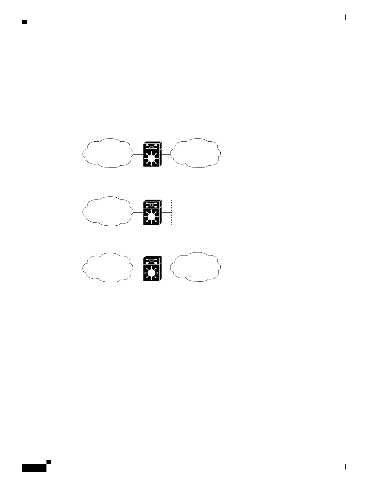
The ATM router module can perform one or more of the functions described in Figure 24-1.
Figure 24-1 ATM Router Module Routing and Bridging Functions
ATM to ATM bridging
Chapter 24 Configuring ATM Router Module Interfaces
ATM
Subnet A
ATM switch
IP routing of ATM to or from ATM and Ethernet
ATM
Subnet B
ATM switch
ATM to ATM routing
ATM
Subnet B
ATM switch
ATM
Subnet A
ATM
Subnet A
ATM
Subnet A
31332
The ATM router module receives Address Resolution Protocol (ARP) messages and route broadcasts
from connected ATM peers and sends the appropriate control information to the route processor. On the
ATM side, the ATM router module connects to the switching fabric as would any other interface module.
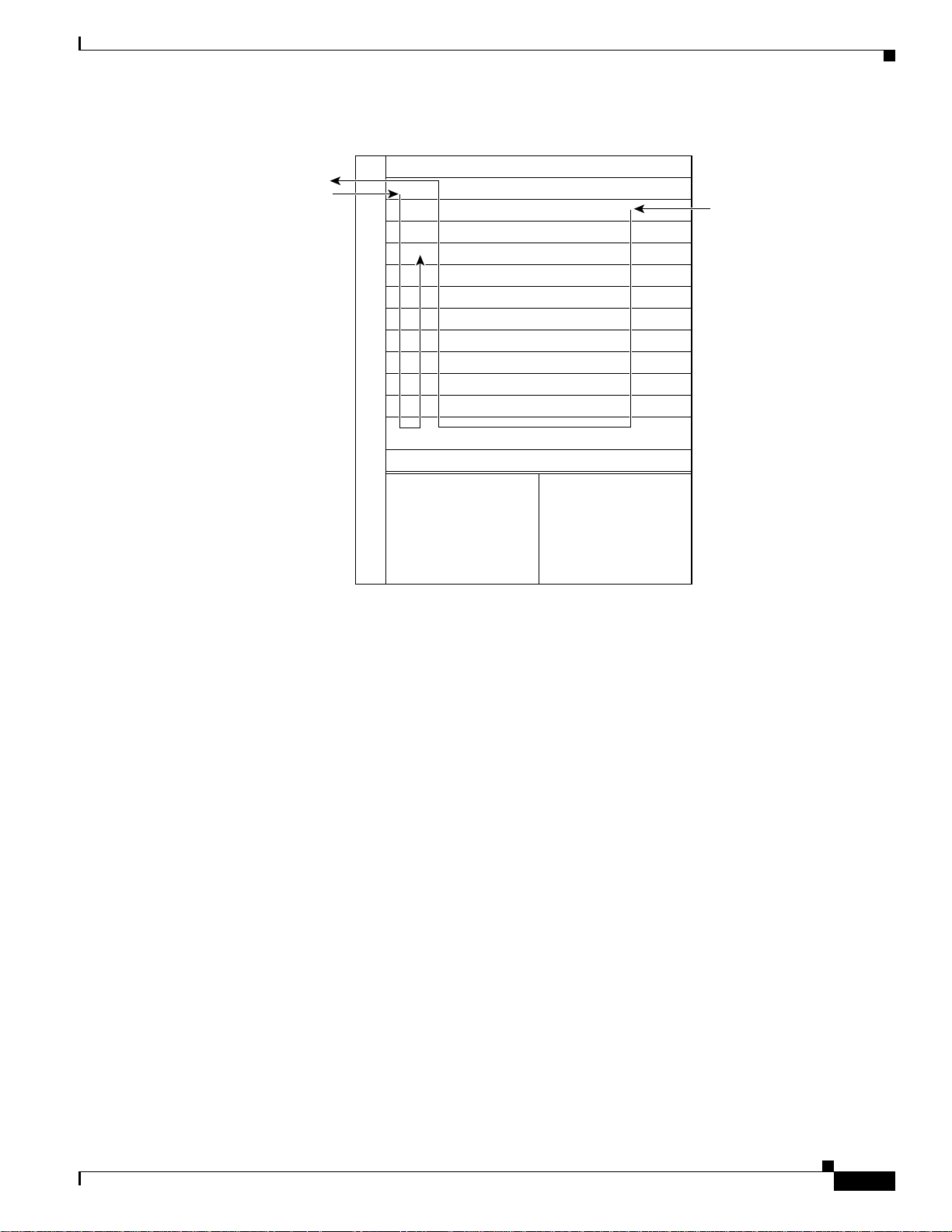
On the Catalyst 8540 MSR, the ATM router module supports LANE clients (LECs), but not LANE
servers (LES, LECS, and BUS). It separates the control and data path so that all LANE control messages
are handled by the route processor, and data messages are switched on the ATM router module port, as
shown in Figure 24-2. The LEC is configured on the ATM router module interface, but control message
traffic is sent to the route processor by the ATM router module. The ATM router module sends all ATM
data traffic to the appropriate VCs.
24-2
ATM and Layer 3 Switch Router Software Configuration Guide
OL-1911-05
Page 3
Chapter 24 Configuring ATM Router Module Interfaces
Figure 24-2 ATM Router Module Traffic Flow (Catalyst 8540 MSR)
Overview of the ATM Router Module
ATM cells NNI
LANE signalling
Interface slot
ATM interface module
FE or GE interface module
Interface slot
Route processor
Switch processor
Switch processor
Switch processor
Route processor
Interface slot
Interface slot
Interface slot
ATM router module
Interface slot
Power supply 1 Power supply 2
IPX packets/
Ethernet frames
31333
Catalyst 8540 MSR Enhanced ATM Router Module Features
The Catalyst 8540 MSR enhanced ATM router module offers the following benefits:
• Interoperates with all of the Layer 3 switching interface modules available for the
Catalyst 8540 CSR chassis. For more information on the Catalyst 8540 CSR Layer 3 interface
modules, refer to the ATM and Layer 3 Module Installation Guide.
• Provides an integrated high performance link between ATM and Layer 3 cards. The ATM router
module provides an aggregate switching capacity of 2 Gbps between ATM and Layer 3 ports
(2 x 1-Gbps interfaces per module). Data transfers to the switch core at the rate of 1 Gbps.
• Simplifies management.
• Hot-swappable.
• Occupies only one slot in the chassis.
• Supports multiprotocol encapsulation over ATM (RFC 1483) switched virtual connections (SVCs),
soft permanent virtual circuits (PVCs) and permanent PVCs with either ATM adaptation layer 5
(AAL5) Subnetwork Access Protocol (SNAP) or AAL5 MUX encapsulation.
• Supports classical ATM over IP (RFC 1577) SVCs and PVCs.
• Standard and extended access control list (ACL) support for IP, and standard ACL support for IPX.
For information configuring on IP ACLs, see Chapter 11, “Using Access Control,” and refer to the
“Configuring IP Services” chapter in the Cisco IOS IP and IP Routing Configuration Guide. For
information configuring on IPX ACLs, refer to the “Configuring Novell IPX” chapter in the Cisco
IOS AppleTalk and Novell IPX Configuration Guide.
OL-1911-05
ATM and Layer 3 Switch Router Software Configuration Guide
24-3
Page 4

Overview of the ATM Router Module
• IP fragmentation support.
• IP 6-path load balancing support.
• Supports OAM-based PVC management.
• Supports Bridge Group Virtual Interface (BVI).
• Supports integrated routing and bridging (IRB).
Note The Catalyst 8540 MSR enhanced ATM router module does not support LANE clients.
The ATM router module has no external interfaces. All traffic is sent and received through internal
interfaces to the switching fabric. The Catalyst 8540 MSR enhanced ATM router module has two
internal ports.
Catalyst 8540 MSR ATM Router Module Features
The Catalyst 8540 MSR ATM router module offers the following benefits:
• Interoperates with all of the Layer 3 switching interface modules available for the
Catalyst 8540 CSR chassis. For more information on the Catalyst 8540 CSR Layer 3 interface
modules, refer to the ATM and Layer 3 Module Installation Guide.
• Provides an integrated high performance link between ATM and Layer 3 cards. The ATM router
module provides an aggregate switching capacity of 2 Gbps between ATM and Layer 3 ports
(2 x 1-Gbps interfaces per module). Data transfers to the switch core at the rate of 1 Gbps.
• Simplifies management.
• Hot-swappable.
• Occupies only one slot in the chassis.
• Supports LANE clients (LECs).
• Supports RFC 1483 SVCs and PVCs with AAL5 SNAP encapsulation.
• Supports RFC 1577 SVCs and PVCs.
• Supports Soft PVCs
• Supports VBR
• Supports Shaped Tunnels
• Supports OAM-based PVC management.
• Supports BVI.
• Supports IRB.
The ATM router module has no external interfaces. All traffic is sent and received through internal
interfaces to the switching fabric. The Catalyst 8540 MSR enhanced ATM router module has two
internal ports.
Chapter 24 Configuring ATM Router Module Interfaces
24-4
ATM and Layer 3 Switch Router Software Configuration Guide
OL-1911-05
Page 5

Chapter 24 Configuring ATM Router Module Interfaces
Hardware and Software Restrictions of the ATM Router Module
Catalyst 8510 MSR and LightStream 1010 ATM Router Module Features
The Catalyst 8510 MSR and LightStream 1010 ATM router module offers the following benefits:
• Interoperates with all of the Layer 3 switching interface modules available for the
Catalyst 8510 CSR chassis. For more information on the Catalyst 8510 CSR Layer 3 interface
modules, refer to the ATM and Layer 3 Module Installation Guide.
• Provides an integrated high performance link between ATM and Layer 3 cards. The ATM router
module provides a switching capacity of 1 Gbps between ATM and Layer 3 ports. Data transfers to
the switch core at the rate of 1 Gbps.
• Simplifies management.
• Hot-swappable.
• Occupies only one slot in the chassis.
• Supports RFC 1483 SVCs and PVCs with AAL5 SNAP encapsulation.
• Supports RFC 1577 SVCs and PVCs.
• Supports OAM-based PVC management.
• Supports BVI.
• Supports IRB.
• Supports VBR.
The ATM router module has no external interfaces. All traffic is sent and received through internal
interfaces to the switching fabric. The Catalyst 8510 MSR and LightStream 1010 ATM router module
has one internal port.
Hardware and Software Restrictions of the ATM Router Module
Hardware Restrictions
The following hardware restrictions apply to the Catalyst 8540 MSR, Catalyst 8510 MSR, and
LightStream 1010 ATM router modules, and the Catalyst 8540 MSR enhanced ATM router modules:
• You can install the ATM router module in any slot except a route processor slot, and, in the case of
the Catalyst 8540 MSR, a switch processor slot.
• The ATM router module is only supported on LightStream 1010 ATM switches with multiservice
ATM switch route processor with FC-PFQ and the Catalyst 8510 MSR system software image.
• You can install up to two ATM router modules per chassis.
• When you hot swap an ATM router module, wait one minute after removing the module before
inserting a new module.
Note The ATM router module is only supported on ATM switches which have multiservice ATM
switch processor installed.
OL-1911-05
ATM and Layer 3 Switch Router Software Configuration Guide
24-5
Page 6

Chapter 24 Configuring ATM Router Module Interfaces
Hardware and Software Restrictions of the ATM Router Module
Catalyst 8540 MSR Enhanced ATM Router Module Software Restrictions
The following software restrictions apply to the Catalyst 8540 MSR enhanced ATM router module:
• LANE is not supported.
• LANE Clients are not supported.
• Use tag switching functionality with caution. Do not distribute routes learned through tag switching
to Fast Ethernet (FE) or Gigabit Ethernet (GE), or vice versa. Otherwise, you might have
unreachable route destinations.
• The ATM router module does not initialize if it replaces an ATM port adapter or interface module
when hierarchical VP tunnels are globally enabled. Reboot the switch to initialize the ATM router
module.
• IP multicast is only supported over 1483 LLC/SNAP encapsulated PVCs.
• ATM Director does not support any PVC commands.
• Even though each ATM router module interface supports a maximum of 2048 VCs, only
1400 to 1500 external VCs can be configured. Internal VCs use up the rest.
• Do not install an ATM router module in a slot pair where hierarchical VP tunnels are configured.
Slot pairs 0 and 1, 2 and 3, 9 and 10, and 11 and 12 use the same switching modules for scheduling.
For example, do not install an ATM router module in slot 10 when hierarchical VP tunnels are
configuredon slot 9. For more information on hierarchical VP tunneling restrictions, see Chapter 6,
“Configuring Virtual Connections.”
The Catalyst 8540 MSR enhanced ATM router modules do not support the following features:
• Tag-edged router functionality
• Fast Simple Server Redundancy Protocol (FSSRP)
• Bridging for multiplexing device encapsulation
• Protocol Independent Multicast (PIM) IP multipoint signalling
• PIM nonbroadcast multiaccess (NBMA)
• PIM over ATM multipoint signalling
• Translation from IP quality of service (QoS) to ATM QoS
• Resource Reservation Protocol (RSVP) to ATM SVC
• PVC management using ILMI
• IP multicast over RFC 1483 SVCs
• Access lists for ATM to ATM routing
• Half-bridge devices
• Layer 2 ACLs
24-6
ATM and Layer 3 Switch Router Software Configuration Guide
OL-1911-05
Page 7

Chapter 24 Configuring ATM Router Module Interfaces
Hardware and Software Restrictions of the ATM Router Module
Catalyst 8540 MSR ATM Router Module Software Restrictions
The following software restrictions apply to the Catalyst 8540 MSR ATM router module:
• Use tag switching functionality with caution. Do not distribute routes learned through tag switching
to FE or GE, or vice versa. Otherwise, you might have unreachable route destinations.
• The ATM router module does not initialize if it replaces an ATM port adapter or interface module
when hierarchical VP tunnels are globally enabled. Reboot the switch to initialize the ATM router
module.
• ATM Director does not support any PVC commands.
• Only LANE clients or RFC 1483, not both, can be configured on an ATM router module interface.
• RFC 1483 on the ATM router module supports only AAL5 SNAP encapsulation.
• Even though each ATM router module interface supports a maximum of 2048 VCs, only
1400 to 1500 external VCs can be configured. Internal VCs use up the rest.
• IP multicast is only supported over 1483 LLC/SNAP encapsulated PVCs.
• You can have a maximum of 64 LECs per chassis.
• Do not install an ATM router module in a slot pair where hierarchical VP tunnels are configured.
Slot pairs 0 and 1, 2 and 3, 9 and 10, and 11 and 12 use the same switching modules for scheduling.
For example, do not install an ATM router module in slot 10 when hierarchical VP tunnels are
configuredon slot 9. For more information on hierarchical VP tunneling restrictions, see Chapter 6,
“Configuring Virtual Connections.”
• Token Ring LANE is not supported.
The Catalyst 8540 MSR ATM router modules do not support the following features:
• Tag-edged router functionality
• Fast Simple Server Redundancy Protocol (SSRP)
• Bridging for multiplexing device encapsulation
• PIM IP multipoint signalling
• PIM NBMA
• PIM over ATM multipoint signalling
• Translation from IP QoS to ATM QoS
• RSVP to ATM SVC
• PVC management using ILMI
• Access lists for ATM to ATM routing
• Half-bridge devices
• RFC 1483 MUX encapsulation
• IP multicast over RFC 1483 SVCs
• ACLs for IP, and standard ACLs for IPX
• IP fragmentation.
• IP 6-path load balancing.
OL-1911-05
ATM and Layer 3 Switch Router Software Configuration Guide
24-7
Page 8

Chapter 24 Configuring ATM Router Module Interfaces
Hardware and Software Restrictions of the ATM Router Module
Catalyst 8540 MSR and LightStream 1010 ATM Router Module Software
Restrictions
The following software restrictions apply to the Catalyst 8540 MSR enhanced ATM router module:
• Use tag switching functionality with caution. Do not distribute routes learned through tag switching
to FE or GE, or vice versa. Otherwise, you might have unreachable route destinations.
• The ATM router module does not initialize if it replaces an ATM port adapter or interface module
when hierarchical VP tunnels are globally enabled. Reboot the switch to initialize the ATM router
module.
• ATM Director does not support any PVC commands.
• RFC 1483 on the ATM router module supports only AAL5 SNAP encapsulation.
• Even though each ATM router module interface supports a maximum of 2048 VCs, only
1400 to 1500 external VCs can be configured. Internal VCs use up the rest.
• Do not install an ATM router module in a slot pair where hierarchical VP tunnels are configured.
Slot pair 0 and 1 and slot pair 3 and 4 use the same switching modules for scheduling. For example,
do not install an ATM router module in slot 1 when hierarchical VP tunnels are configured on slot 0.
For more information on hierarchical VP tunneling restrictions, see Chapter 6, “ConfiguringVirtual
Connections.”
• RFC 1577 SVCs
• LANE clients are not supported.
• Only UBR PVCs are supported.
• IP multicast is only supported over 1483 LLC/SNAP encapsulated PVCs.
The Catalyst 8510 MSR and LightStream 1010 ATM router modules do not support the following
features:
• Point-to-point subinterfaces. Only point-to-multipoint subinterfaces are supported.
• Tag-edged router functionality
• SSRP
• Bridging for multiplexing device encapsulation
• Protocol Independent Multicast (PIM) IP multipoint signalling
• PIM nonbroadcast multiaccess (NBMA)
• PIM over ATM multipoint signalling
• Translation from IP quality of service (QoS) to ATM QoS
• Resource Reservation Protocol (RSVP) to ATM SVC
• PVC management using ILMI
• Access lists for ATM to ATM routing
• Half-bridge devices
• RFC 1483 MUX encapsulation
• IP multicast over RFC 1483 SVCs
• ACLs for IP, and standard ACLs for IPX
24-8
ATM and Layer 3 Switch Router Software Configuration Guide
OL-1911-05
Page 9

Chapter 24 Configuring ATM Router Module Interfaces
• IP fragmentation.
• IP 6-path load balancing.
Note The ATM router module is only supported on ATM switches which have a multiservice ATM switch
processor installed.
Note The LightStream 1010 system software image does not include support for the ATM router module
or Layer 3 features. You can download this image to a LightStream 1010 ATM switch router with a
multiservice ATM switch processor installed.
Configuring ATM Router Module Interfaces
The you can configure the following features directly on the ATM router module interfaces:
• Maximum virtual channel identifier (VCI) bits
• Maximum Transmission Units (MTUs) (enhanced Catalyst 8540 MSR)
• LANE clients (Catalyst 8540 MSR)
• RFC 1483
• Classical IP over ATM (RFC 1577)
• Bridging
• IP multicast
Configuring ATM Router Module Interfaces
Note This document describes how to configure ATM software features combined with Layer 3 features
only. For more detailed information on how to configure the Layer 3 modules that interoperate with
the ATM router module in the Catalyst 8540 MSR chassis, refer to the Layer 3 Switching Software
Feature and ConfigurationGuide, which is available on the Documentation CD-ROMthat came with
your ATM switch router, online at Cisco.com, or when ordered separately as a hard copy document.
Note ATM router modules have internal interfaces, but no external ports. Use the interface atm
card/subcard/port command to specify these interfaces.
Note Virtualpathidentifier(VPI)2 is reserved for ATM router module interfaces, which allowsup to 2048
external VCs on each ATM router module interface. Using VPI 0 would haveallowed less than 1024
external VCs on an ATM router module interface because the ATM router module external VCs
would have been forced to share the VC space within VPI 0 with the internal PVCs.
Even though each ATM router module interface supports a maximum of 2048 VCs, only
1400 to 1500 external VCs can be configured. Internal VCs use up the rest.
OL-1911-05
ATM and Layer 3 Switch Router Software Configuration Guide
24-9
Page 10

Chapter 24 Configuring ATM Router Module Interfaces
Configuring ATM Router Module Interfaces
DefaultATMRouterModuleInterfaceConfigurationWithoutAutoconfiguration
If ILMI is disabled or if the connecting end node does not support ILMI, the following defaults are
assigned to all ATM router module interfaces:
• ATM interface type = UNI
• UNI version = 3.0
• Maximum VCI bits = 11
• MTU size = 1500 bytes
• ATM interface side = network
• ATM UNI type = private
Note Only Catalyst 8540 MSR enhanced ATM router module interfaces support IP unicast and IP
multicast fragmentation. For IP unicast fragmentation, the packet must ingress on an enhanced ATM
router module interface and egresson any interface. For IP multicast fragmentation, IP multicast data
packets greater than 1500 bytes are fragmented to 1500 bytes on the ingress enhanced ATM router
module interface before being switched to other members in the multicast group. All the members in
the multicast group must have an MTU equal to or greater than 1500 bytes.
Manual ATM Router Module Interface Configuration
To manually change the default configuration values, perform the following steps, beginning in global
configuration mode:
Command Purpose
Step 1
Step 2
Step 3
Switch(config)# interface atm card/subcard/port
Switch(config-if)#
Specifies an ATM interface and enters interface
configuration mode.
Switch(config-if)# atm maxvci-bits max-vci-bits Modifies the maximum number of active
VCI bits.
Switch(config-if)# mtu bytes Modifies the MTU size. The default MTU size is
1500 bytes.
Note Only Catalyst 8540 MSR enhanced ATM
Example
The following example shows how to change the default number of active VCI bits:
Switch(config)# interface atm 0/0/0
Switch(config-if)# atm maxvci-bits 10
router modules support variable MTU
sizes.
24-10
ATM and Layer 3 Switch Router Software Configuration Guide
OL-1911-05
Page 11

Chapter 24 Configuring ATM Router Module Interfaces
Configuring LECs on ATM Router Module Interfaces (Catalyst 8540 MSR)
Configuring LECs on ATM Router Module Interfaces
(Catalyst 8540MSR)
The procedures for configuring LANE clients (LECs) on the ATM router module are the same as for the
configuration of LECs on the route processor, with one exception: To specify an ATM router module
interface, rather than the route processor interface, use the interface atm card/subcard/port command.
On the route processor, you would use the interface atm 0 command.
Note To route traffic between an emulated LAN and a Fast Ethernet (FE) or Gigabit Ethernet (GE)
interface, you must configure the LEC on an ATM router module interface rather than a route
processor interface.
Note An ATM router module interface can be configured for either LECs or RFC 1483 PVCs, not both.
For both features to operate on the same ATM router module, configure LECs on one interface and
RFC 1483 PVCs on the other.
Note LANE clients are not supported on the Catalyst 8540 MSR enhanced ATM router module.
To configure a LEC on an ATM router module interface, use the following commands, beginning in
global configuration mode:
Command Purpose
Step 1
Step 2
Step 3
Switch(config)# interface atm
card/subcard/port.subinterface# multipoint
Switch(config-subif)#
Switch(config-subif)#ip address ip-address mask Provides a protocol address and subnet mask for
Switch(config-subif)# lane client ethernet
elan-name
Creates the ATM router module
point-to-multipoint subinterface and enters
subinterface mode.
Note The ATM router module only supports
point-to-multipoint subinterfaces.
the client on this subinterface.
Enables a LANE client for an emulated LAN.
OL-1911-05
ATM and Layer 3 Switch Router Software Configuration Guide
24-11
Page 12

Configuring LECs on ATM Router Module Interfaces (Catalyst 8540 MSR)
Example
The following example shows how to configure two LECs on an ATM router module interface:
Switch# configure terminal
Switch(config)# interface atm 1/0/0.4 multipoint
Switch(config-subif)# ip address 40.0.0.1 255.0.0.0
Switch(config-subif)# lane client ethernet VLAN4
Switch(config-subif)# exit
Switch(config)# interface atm 1/0/0.5 multipoint
Switch(config-subif)# ip address 50.0.0.1 255.0.0.0
Switch(config-subif)# lane client ethernet VLAN5
Switch(config-subif)# exit
Switch(config)# router ospf 1
Switch(config-router)# network 40.0.0.0 0.255.255.255 area 0
Switch(config-router)# network 50.0.0.0 0.255.255.255 area 0
For more information on configuring LECs on ATM router module interfaces, see Chapter 13,
“Configuring LAN Emulation.” For a detailed description of LANE and its components, refer to
Cisco IOS Switching Services Configuration Guide: Virtual LANs.
LEC Configuration Examples
Chapter 24 Configuring ATM Router Module Interfaces
The examples in this section show how to configure LANE clients (LECs) on networks with two routers
and one Catalyst 8540 MSR. For detailed information on configuring the LANE server (LES), LANE
configuration server (LECS), and broadcast-and-unknown server (BUS), see Chapter 13, “Configuring
LAN Emulation.”
Caution For performance reasons, avoid configuring the LANE server components on ATM switch routers.
Instead, configure the LANE server components on a router such as a Cisco 7500 series router or a
Catalyst 5500 router with a LANE module installed.
LANE Routing Over ATM
The following example shows how to configure LANE routing over ATM using the ATM router module.
Figure 24-3 shows an example of a network for LANE routing over ATM.
Figure 24-3 Example Network for LANE Routing over ATM
Router 1 Router 2
Catalyst 8540 MSR
ATM 2/0 ATM 3/0
ATM router module
Interface ATM 2/0/0
45158
24-12
ATM and Layer 3 Switch Router Software Configuration Guide
OL-1911-05
Page 13

Chapter 24 Configuring ATM Router Module Interfaces
Router 1 ATM Interface
Router1# configure terminal
Router1(config)# interface atm 2/0
Router1(config-if)# ip address 1.0.0.1 255.0.0.0
Router1(config-if)# atm pvc 1 0 5 qsaal
Router1(config-if)# atm pvc 2 0 16 ilmi
Router1(config-if)# lane client ethernet happy
Router1(config-if)# end
Router1#
ATM Switch Router ATM Router Module Interface
Switch# configure terminal
Switch(config)# interface atm 2/0/0
Switch(config-if)# ip address 1.0.0.2 255.0.0.0
Switch(config-if)# lane client ethernet BACKBONE
Switch(config-if)# end
Switch#
Router 2 ATM Interface
Router2# configure terminal
Router2(config)# interface atm 3/0
Router2(config-if)# ip address 1.0.0.3 255.0.0.0
Router2(config-if)# no ip mroute-cache
Router2(config-if)# atm pvc 1 0 5 qsaal
Router2(config-if)# atm pvc 2 0 16 ilmi
Router2(config-if)# no atm ilmi-keepalive
Router2(config-if)# lane client ethernet BACKBONE
Router2(config-if)# end
Router2#
Configuring LECs on ATM Router Module Interfaces (Catalyst 8540 MSR)
For detailed information on configuring LANE clients (LECs), see Chapter 13, “Configuring
LAN Emulation.”
LANE Routing from ATM to Ethernet
The following example shows how to configure LANE routing from ATM to Ethernet using the ATM
router module. Figure 24-4 shows an example of a LANE network for LANE routing from ATM to
Ethernet.
Figure 24-4 Example Network for LANE Routing from ATM to Ethernet
Router 1 Router 2
ATM 2/0
Catalyst 8540 MSR
GE 9/0/0
ATM router module
Interface ATM 2/0/0
GE 9/0/0
45222
OL-1911-05
ATM and Layer 3 Switch Router Software Configuration Guide
24-13
Page 14

Configuring LECs on ATM Router Module Interfaces (Catalyst 8540 MSR)
Router 1 ATM Interface
Router1# configure terminal
Router1(config)# interface atm 2/0
Router1(config-if)# ip address 1.0.0.1 255.0.0.0
Router1(config-if)# atm pvc 1 0 5 qsaal
Router1(config-if)# atm pvc 2 0 16 ilmi
Router1(config-if)# lane client ethernet happy
Router1(config-if)# end
Router1#
ATM Switch Router ATM Router Module Interface
Switch# configure terminal
Switch(config)# interface atm 2/0/0
Switch(config-if)# ip address 1.0.0.2 255.0.0.0
Switch(config-if)# lane client ethernet BACKBONE
Switch(config-if)# end
Switch#
ATM Switch Router Ethernet Interface
Switch# configure terminal
Switch(config)# interface gigabitethernet 9/0/0
Switch(config-if)# ip address 129.1.0.1 255.255.255.0
Switch(config-if)# no ip directed-broadcast
Switch(config-if)# end
Switch#
Chapter 24 Configuring ATM Router Module Interfaces
Router 2 Ethernet Interface
Router2# configure terminal
Router2(config)# interface gigabitethernet 9/0/0
Router2(config-if)# ip address 129.1.0.2 255.255.255.0
Router2(config-if)# no ip directed-broadcast
Router2(config-if)# end
Router2#
Configure the desired network routing protocol, such as RIP, OSPF, or EIGRP, on Ethernet interfaces.
For more information on configuring networking protocols and routing, refer to the Layer 3 Software
Configuration Guide.
24-14
ATM and Layer 3 Switch Router Software Configuration Guide
OL-1911-05
Page 15

Chapter 24 Configuring ATM Router Module Interfaces
LANE Bridging Between ATM and Ethernet
The following example show how to configure LANE bridging between ATM and Ethernet using the
ATM router module. Figure 24-5 shows an example of a network for LANE bridging between ATM and
Ethernet.
Figure 24-5 Example Network for LANE Bridging Between ATM and Ethernet
Configuring LECs on ATM Router Module Interfaces (Catalyst 8540 MSR)
Router 1 Router 2
Catalyst 8540 MSR
GE 9/0/0
ATM 2/0
GE 9/0/0
ATM router module
Interface ATM 2/0/0
Router 1 ATM Interface
Router1# configure terminal
Router1(config)# interface atm 2/0
Router1(config-if)# atm pvc 1 0 5 qsaal
Router1(config-if)# atm pvc 2 0 16 ilmi
Router1(config-if)# lane client ethernet happy
Router1(config-if)# bridge-group 1
Router1(config-if)# end
Router1#
Router 1 Bridge Interface
Router1# configure terminal
Router1(config)# interface BVI1
Router1(config-if)# ip address 130.2.3.1 255.255.255.0
Router1(config-if)# exit
Router1(config)# bridge 1 protocol ieee
Router1(config)# bridge 1 route ip
Router1(config)# bridge irb
Router1(config)# end
Router1#
45222
OL-1911-05
ATM Switch Router ATM Router Module Interface
Switch# configure terminal
Switch(config)# interface atm 2/0/0
Switch(config-if)# lane client ethernet BACKBONE
Switch(config-if)# bridge-group 1
Switch(config-if)# exit
Switch(config)# bridge 1 protocol ieee
Switch(config)# end
Switch#
ATM Switch Router Ethernet Interface
Switch# configure terminal
Switch(config)# interface gigabitethernet9/0/0
Switch(config-if)# bridge-group 1
Switch(config-if)# end
Switch#
ATM and Layer 3 Switch Router Software Configuration Guide
24-15
Page 16

Configuring Multiprotocol Encapsulation over ATM
Router 2 Ethernet Interface
Router2# configure terminal
Router2(config)# interface ethernet 9/0/0
Router2(config-if)# bridge-group 1
Router2(config-if)# end
Router2#
Router 2 Bridge Interface
Router2# configure terminal
Router2(config)# interface BVI1
Router2(config-if)# ip address 130.2.3.4 255.255.255.0
Router2(config-if)# exit
Router2(config)# bridge 1 protocol ieee
Router2(config)# bridge 1 route ip
Router2(config)# bridge irb
Router2(config)# end
Router2#
For more information on configuring bridging, refer to the Layer 3 Software Configuration Guide.
Confirming the LEC Configuration
Chapter 24 Configuring ATM Router Module Interfaces
To confirm the LEC configuration on the ATM switch router, use the following EXEC commands:
Command Purpose
show lane [interface atm
card/subcard/port[.subinterface#] |
name elan-name] [brief]
Displays the global and per-virtual channel
connection LANE information for all the LANE
components and emulated LANs configured on
an interface or any of its subinterfaces.
show lane client [interface atm
card/subcard/port[.subinterface#] |
name elan-name] [brief]
show lane config [interface atm
card/subcard/port[.subinterface#]]
Displays the global and per-VCC LANE
information for all LANE clients configured on
any subinterface or emulated LAN.
Displays the global and per-VCC LANE
information for the configuration server
configured on any interface.
Configuring Multiprotocol Encapsulation over ATM
This section describes howtoconfiguremultiprotocolencapsulation over ATM, as definedin RFC 1483,
on the ATM router module.
The primary use of multiprotocol encapsulation over ATM, also know as RFC 1483, is carrying multiple
Layer 3 and bridged frames over ATM. RFC 1483 traffic is routed through an ATM router module
interface using static map lists. Static map lists provide an alternative to using the ATM Address
Resolution Protocol (ARP) and ATM InverseARP (InARP) mechanisms. Formore information on static
map lists, see Chapter 12, “Configuring IP over ATM.”
For a detailed description of multiprotocol encapsulation over ATM, refer to the Guide to ATM
Technology.
24-16
ATM and Layer 3 Switch Router Software Configuration Guide
OL-1911-05
Page 17

Chapter 24 Configuring ATM Router Module Interfaces
Note Traffic shaping and policing are not supported on the ATM router module interfaces; for traffic
shaping and policing on ATMconnections, use VP tunnels. For more information on VP tunnels, see
Chapter 6, “Configuring Virtual Connections.”
To configure multiprotocol encapsulation over ATM on the ATM router module interface, use the
following commands, beginning in global configuration mode:
Command Purpose
Step 1
Switch(config)# interface atm
card/subcard/port.subinterface# multipoint
Switch(config-subif)#
Step 2
Step 3
Step 4
Switch(config-subif)#ip address ip-address mask Entersthe IP address and subnet mask associated
Switch(config-subif)# map-group name Enters the map group name associated with this
Switch(config-subif)# atm pvc 2 vci-a [upc upc]
[pd pd] [rx-cttr index] [tx-cttr index] interface
atm card/subcard/port[.vpt#] vpi-b vci-b
[upc upc] encap {aal5mux1 | aal5snap}
Step 5
Switch(config-subif)# exit
Switch(config)#
Step 6
Switch(config)# map-list name
Switch(config-map-list)#
Step 7
Switch(config-map-list)# ip ip-address
{atm-nsap address | atm-vc vci} [broadcast]
1. Only the Catalyst 8540 MSR enhanced ATM router module supports AAL5 MUX encapsulation.
Configuring Multiprotocol Encapsulation over ATM
Creates the ATM router module
point-to-multipoint subinterface and enters
subinterface mode.
Note The ATM router module only supports
point-to-multipoint subinterfaces.
with this interface.
PVC.
Configures the PVC.
Note The VPI number on the ATM router
module interface must be 2.
Returns to global configuration mode.
Creates a map list by naming it, and enters
map-list configuration mode.
Associates a protocol and address with a specific
virtual circuit.
OL-1911-05
Example
The following example shows how to configure RFC 1483 on an ATM router module interface,
beginning in global configuration mode:
Switch(config)# interface atm 1/0/0.1011 multipoint
Switch(config-subif)# ip address 10.1.1.1 255.255.255.0
Switch(config-subif)# map-group net1011
Switch(config-subif)# atm pvc 2 1011 interface atm 3/0/0 0 1011 encap aal5snap
Switch(config-subif)# exit
Switch(config)# map-list net1011
Switch(config-map-list)# ip 10.1.1.2 atm-vc 1011
Switch(config-map-list)# end
Switch#
ATM and Layer 3 Switch Router Software Configuration Guide
24-17
Page 18

Chapter 24 Configuring ATM Router Module Interfaces
Configuring Multiprotocol Encapsulation over ATM
Multiprotocol Encapsulation over ATM Configuration Example
The following example shows how to configure for multiprotocol encapsulation over ATM with two
routers and a ATM switch router.
The ATM switch router has an ATM router module in slot 0, a Fast Ethernet interface module in slot 1,
and an ATM interface module in slot 3. One router has an ATM interface processor in slot 3. The other
router has a Fast Ethernet interface module in slot 2.
Figure 24-6 shows an example of an RFC 1483 network.
Figure 24-6 Example Network for RFC 1483
ATM switch
RFC 1483 router Ethernet router
10.1.1.2
10.1.1.1
IF = atm 3/0.1011
router
20.1.1.2
IF = fa 1/0/0
IF = atm 3/0/0.1011
20.1.1.1
IF = fa 2/0
38493
Router with ATM Interface
RouterA# configure terminal
RouterA(config)# interface atm 3/0.1011 multipoint
RouterA(config-subif)# ip address 10.1.1.2 255.255.255.0
RouterA(config-subif)# atm pvc 1011 0 1011 aal5snap
RouterA(config-subif)# map group net1011
RouterA(config-subif)# ipx network 1011
RouterA(config-subif)# exit
RouterA(config)# map-list net1011
RouterA(config-map-list)# ip 10.1.1.1 atm-vc 1011
RouterA(config-map-list)# ipx 1011.1111.1111.1111 atm-vc 1011
RouterA(config-map-list)# exit
RouterA(config)#
ATM Switch Router
Switch# configure terminal
Switch(config)# interface atm 0/0/0.1011 multipoint
Switch(config-subif)# ip address 10.1.1.1 255.255.255.0
Switch(config-subif)# ipx network 1011
Switch(config-subif)# map-group net1011
Switch(config-subif)# atm pvc 2 1011 interface atm 3/0/0 0 1011
Switch(config-subif)# map-list net1011
Switch(config-map-list)# ip 10.1.1.2 atm-vc 1011
Switch(config-map-list)# ipx 1011.2222.2222.2222 atm-vc 1011
Switch(config-map-list)# exit
Switch(config)# interface fastethernet 1/0/0
Switch(config-if)# ip address 20.1.1.2 255.255.255.0
Switch(config-if)# ipx network 2011
Switch(config-if)# end
Switch#
24-18
Note The VCI in the atm pvc command must match the atm-vc VCI in the map list.
ATM and Layer 3 Switch Router Software Configuration Guide
OL-1911-05
Page 19

Chapter 24 Configuring ATM Router Module Interfaces
Configuring Classical IP over ATM in a PVC Environment
Ethernet Router
RouterB# configure terminal
RouterB(config)# ipx routing
RouterB(config)# interface fastethernet 2/0
RouterB(config-if)# ip address 20.1.1.1 255.255.255.0
RouterB(config-if)# ipx network 2011
RouterB(config-if)# end
RouterB#
Configuring Classical IP over ATM in a PVC Environment
This section describes how to configure classical IP over ATM, as described in RFC 1577, in a PVC
environment on the ATM router module. The ATM Inverse ARP (InARP) mechanism is applicable to
networks that use permanent virtual connections (PVCs), where connections are established but the
network addresses of the remote ends are not known. For more information on configuring ATM ARP
and ATM InARP, see Chapter 12, “Configuring IP over ATM,”
For a description of classical IP over ATM and RFC 1577, refer to the Guide to ATM Technology.
In a PVC environment, configurethe ATM InARP mechanism on the ATM router module by performing
the following steps, beginning in global configuration mode:
Step 1
Step 2
Step 3
Command Purpose
Switch(config)# interface atm card/subcard/port
Switch(config-if)#
Specifies the ATM router module interface to
configure.
Switch(config-if)# ip address ip-address mask Specifies the IP address of the interface.
Switch(config-if)# atm pvc 2 vci interface atm
card/subcard/port vpi vci encap {aal5mux1 |
aal5snap}[inarp minutes]
1. Only the Catalyst 8540 MSR enhanced ATM router module supports AAL5 MUX encapsulation.
Creates a PVC and enables ATM InARP.
Note The VPI number on the ATM router
module interface must be 2.
Repeat these tasks for each PVC you want to create.
The inarp minutes interval specifies how often inverse ARP datagrams are sent on this virtual circuit.
The default value is 15 minutes.
Example
The following example shows how to configure an IP-over-ATM interface on interface ATM 3/0/0, using
a PVC with AAL5SNAP encapsulation, InARP set to ten minutes, VPI = 2, and VCI = 100:
Switch(config)# interface atm 3/0/0
Switch(config-if)# ip address 11.11.11.11 255.255.255.0
Switch(config-if)# atm pvc 2 100 interface atm 0/0/0 50 100 encap aal5snap inarp 10
Configuring Classical IP over ATM in an SVC Environment
This section describes how to configure classical IP over ATM in an SVC environment on your ATM
router module. It requires configuring only the device’s own ATM address and that of a single ATM
Address Resolution Protocol (ARP) server into each client device.
ATM and Layer 3 Switch Router Software Configuration Guide
OL-1911-05
24-19
Page 20

Configuring Classical IP over ATM in an SVC Environment
For a detailed description of the role and operation of the ATM ARP server, refer to the Guide to ATM
Technology.
The ATM switch router can be configured as an ATM ARP client, thereby being able to work with any
ATM ARP server conforming to RFC 1577. Alternatively, one of the ATM switch routers in a logical IP
subnet (LIS) can be configured to act as the ATMARP server itself. In that case, it automatically acts as
a client as well. The following sections describe configuring the ATM switch router in an SVC
environment as either an ATM ARP client or an ATM ARP server.
Configuring as an ATM ARP Client
In an SVC environment, configure the ATM ARP mechanism on the interface by performing the
following steps, beginning in global configuration mode:
Command Purpose
Step 1
Step 2
Step 3
Step 4
Step 5
Step 6
Switch(config)# interface atm card/subcard/port
Switch(config-if)#
Switch(config-if)# atm nsap-address
nsap-address
or
Switch(config-if)# atm esi-address esi.selector
Switch(config-if)# ip address ip-address mask Specifies the IP address of the interface.
Switch(config-if)# atm arp-server nsap
nsap-address
Switch(config-if)# exit
Switch(config)#
Switch(config)# atm route addr-prefix1atm
card/subcard/port internal
1. The address prefix is the first 19 bytes of the NSAP address.
Chapter 24 Configuring ATM Router Module Interfaces
Selects the ATM router module interface.
Specifies the network service access point
(NSAP) ATM address of the interface.
or
Specifiesthe end-system-identifier (ESI) address
of the interface.
Specifies the ATM address of the ATM ARP
server.
Exits interface configuration mode.
Configuresa static route through the ATM router
module interface. See the note that follows this
table.
24-20
Note The end system identifier (ESI) address form is preferred, in that it automatically handles the
advertising of the address. Use the network service access point (NSAP) form of the command when
you need to define a full 20-byte unique address with a prefix unrelated to the network prefix on that
interface. You only need to specify a static route when configuring an ARP client using an NSAP
address.
ATM and Layer 3 Switch Router Software Configuration Guide
OL-1911-05
Page 21

Chapter 24 Configuring ATM Router Module Interfaces
NSAP Address Example
Figure 24-7 shows three ATM switch routers and a router connected using classical IP over ATM.
Figure 24-7 Classical IP over ATM Connection Setup
Configuring Classical IP over ATM in an SVC Environment
Switch client B
123.233.45.3
Router client C
123.233.45.6
ATM network
123.233.45.0
Switch ARP server
123.233.45.2
Switch client A
123.233.45.1
27082
The following example shows how to configure the ATM router module interface ATM 1/0/0 of Client A
in Figure 24-7, using the NSAP address:
Client A(config)# interface atm 1/0/0
Client A(config-if)# atm nsap-address 47.0091.8100.0000.1111.1111.1111.1111.1111.1111.00
Client A(config-if)# ip address 123.233.45.1 255.255.255.0
Client A(config-if)# atm arp-server nsap 47.0091.8100.0000.1111.1111.1111.2222.2222.2222.00
Client A(config-if)# exit
Client A(config)# atm route 47.0091.8100.0000.1111.1111.1111.1111.1111.1111 atm 1/0/0 internal
ESI Example
The following example shows how to configure the ATM router module interface ATM 1/0/0 of Client A
in Figure 24-7, using the ESI:
Client A(config)# interface atm 1/0/0
Client A(config-if)# atm esi-address 0041.0b0a.1081.40
Client A(config-if)# ip address 123.233.45.1 255.255.255.0
Client A(config-if)# atm arp-server nsap 47.0091.8100.0000.1111.1111.1111.2222.2222.2222.00
Client A(config-if)# exit
OL-1911-05
ATM and Layer 3 Switch Router Software Configuration Guide
24-21
Page 22

Configuring Classical IP over ATM in an SVC Environment
Configuring as an ATM ARP Server
Cisco’simplementation of the ATM ARP server supports a single, nonredundant server per LIS, and one
ATM ARP server per subinterface. Thus, a single ATM switch router can support multiple ARP servers
by using multiple interfaces.
To configure the ATM ARP server, perform the following steps, beginning in global configuration mode:
Command Purpose
Step 1
Step 2
Step 3
Step 4
Step 5
Switch(config)# interface atm
card/subcard/port[.subinterface#]
Switch(config-if)#
Switch(config-if)# atm nsap-address
nsap-address
or
Switch(config-if)# atm esi-address esi.selector
Switch(config-if)# ip address ip-address mask Specifies the IP address of the interface.
Switch(config-if)# atm arp-server time-out
minutes
1
Switch(config-if)# atm route addr-prefix2atm
card/subcard/port internal
1. Thisform of the atm arp-server command indicates that this interface performs the ATM ARP server functions. When you
configure the ATM ARP client (described earlier), the atm arp-server command is used—with a different keyword and
argument—to identify a different ATM ARP server to the client.
2. Address prefix is the first 19 bytes of the NSAP address.
Chapter 24 Configuring ATM Router Module Interfaces
Selects the Catalyst 8540 MSR enhanced ATM
router module interface.
SpecifiestheNSAP ATM address of the interface.
or
Specifiestheend-system-identifieraddressof the
interface.
Configures the ATM ARP server optional idle
timer.
Configures a static route through the optional
ATM router module interface.
24-22
Note The ESI address form is preferred in that it automatically handles the advertising of the address. Use
the NSAP form of the command when you need to define a full 20-byte unique address with a prefix
unrelated to the network prefix on that interface. You only need to specify a static route when
configuring an ARP server using an NSAP address.
The idle timer interval is the number of minutes a destination entry listed in the ATM ARP server’sARP
table can be idle before the server takes any action to timeout the entry.
Example
The following example configures the route processor interface ATM 0 as an ARP server (shown in
Figure 24-7):
ARP_Server(config)# interface atm 1/0/0
ARP_Server(config-if)# atm esi-address 0041.0b0a.1081.00
ARP_Server(config-if)# atm arp-server self
ARP_Server(config-if)# ip address 123.233.45.2 255.255.255.0
ATM and Layer 3 Switch Router Software Configuration Guide
OL-1911-05
Page 23

Chapter 24 Configuring ATM Router Module Interfaces
Displaying the IP-over-ATM Interface Configuration
To show the IP-over-ATM interface configuration, use the following EXEC commands:
Command Purpose
show atm arp-server Shows the ATM interface ARP configuration.
show atm map Shows the ATM map list configuration.
Examples
In the following example, the showatm arp-server command displays the configurationofthe interface
ATM 1/0/0:
Switch# show atm arp-server
Note that a '*' next to an IP address indicates an active call
IP Address TTL ATM Address
ATM1/0/0:
* 10.0.0.5 19:21 4700918100567000000000112200410b0a108140
Configuring Classical IP over ATM in an SVC Environment
The following example displays the map-list configuration of the static map and IP-over-ATM
interfaces:
Switch# show atm map
Map list ATM1/0/0_ATM_ARP : DYNAMIC
arp maps to NSAP 36.0091810000000003D5607900.0003D5607900.00
, connection up, VPI=0 VCI=73, ATM2/0/0
ip 5.1.1.98 maps to s 36.0091810000000003D5607900.0003D5607900.00
, broadcast, connection up, VPI=0 VCI=77, ATM2/0/0
Map list ip : PERMANENT
ip 5.1.1.99 maps to VPI=0 VCI=200
OL-1911-05
ATM and Layer 3 Switch Router Software Configuration Guide
24-23
Page 24

Configuring Bridging
Configuring Bridging
All PVCs configured on ATM router module interfaces are used for bridging.
To configure bridging on an ATM router module interface, use the following commands, beginning in
global configuration mode:
Command Purpose
Step 1
Step 2
Step 3
Step 4
Step 5
Step 6
Step 7
Step 8
Step 9
Switch(config)# interface atm card/subcard/port
Switch(config-if)#
Switch(config-if)# atm pvc 2 vci interface atm
card/subcard/port vpi
Switch(config-if)# bridge-group number Assigns the interface to a bridge group.
Switch(config-if)# end
Switch(config)#
Switch(config)# interface fastethernet
card/subcard/port
Switch(config-if)#
Switch(config-if)# no cdp enable Disables Cisco Discovery Protocol on the
Switch(config-if)# bridge-group number Assigns the interface to a bridge group.
Switch(config-if)# end
Switch(config)#
Switch(config)# bridge number protocol ieee Specifies the IEEE 802.1D Spanning-Tree
Chapter 24 Configuring ATM Router Module Interfaces
Specifiesthe interface on the ATM router module
to configure.
Configures a PVC.
Note The VPI number on the ATM router
module interface must be 2.
Returns to global configuration mode.
Specifies the Fast Ethernet interface to configure.
interface.
Returns to global configuration mode.
Protocol for the bridge group.
24-24
Example
The following example shows how to configure bridging on a Catalyst 8540 MSR with a Fast Ethernet
interface module in slot 0, an ATM interface module in slot 1, and an ATM router module in slot 3.
Figure 24-8 shows an example bridging network.
Figure 24-8 Example Network for Bridging
Cisco 7500 router A
10.10.10.2
IF = atm 0
MAC addr = 0000.0CAC.BE94
ATM and Layer 3 Switch Router Software Configuration Guide
IF = atm 1/0/0
ATM switch
router
IF = fa 0/0/0
MAC addr = 0060.3E59.C63C
Cisco 7500 router B
10.10.10.1
IF = e0
38492
OL-1911-05
Page 25

Chapter 24 Configuring ATM Router Module Interfaces
Switch(config)# interface atm 3/0/0
Switch(config-if)# atm pvc 2 200 interface atm 1/0/0 0 200
Switch(config-if)# bridge-group 5
Switch(config-if)# end
Switch(config)# interface fastethernet 0/0/0
Switch(config-if)# no cdp enable
Switch(config-if)# bridge-group 5
Switch(config-if)# end
Switch(config)# bridge 5 protocol ieee
Configuring Packet Flooding on a PVC
Typically, a specific static map list configuration is not required for bridging to occur. In case of packet
flooding,the bridging mechanism individually sends the packet to be flooded on all PVCs configured on
the interface. To restrict the broadcast of the packets to only a subset of the configured PVCs you must
define a separate static map list. Use the broadcast keyword in the static-map command to restrict
packet broadcasting.
Command Purpose
Step 1
Step 2
Step 3
Step 4
Step 5
Step 6
Step 7
Step 8
Step 9
Switch(config)# interface atm card/subcard/port
Switch(config-if)#
Switch(config-if)# no ip address Disables IP processing.
Switch(config-if)# no ip directed-broadcast Disables the translation of directed broadcasts to
Switch(config-if)# map-group number Enters the map group name associated with this
Switch(config-if)#atmpvc 2 vci-A interface atm
card/subcard/port vpi-B
Switch(config-if)# bridge-group number Assigns the interface to a bridge group.
Switch(config-if)# end
Switch(config)#
Switch(config)# map-list name
Switch(config-map-list)#
Switch(config-map-list)# bridge atm-vc number
broadcast
Configuring Bridging
Specifies the interface to configure on the ATM
router module.
physical broadcasts.
PVC.
Configures a PVC.
Note The VPI number on the ATM router
module interface must be 2.
Returns to global configuration mode.
Creates a map list by naming it, and enters
map-list configuration mode.
Enables packet flooding on a PVC.
OL-1911-05
ATM and Layer 3 Switch Router Software Configuration Guide
24-25
Page 26

Configuring Bridging
Example
In the following example only PVC 2, 200 is used for packet flooding:
Switch(config)# interface atm 3/0/0
Switch(config-if)# no ip address
Switch(config-if)# no ip directed-broadcast
Switch(config-if)# map-group bg_1
Switch(config-if)# atm pvc 2 200 interface atm 1/0/1 0 200
Switch(config-if)# atm pvc 2 201 interface atm 1/0/1 0 300
Switch(config-if)# bridge-group 5
Switch(config-if)# end
Switch(config)# map-list bg_1
Switch(config-map-list)# bridge atm-vc 200 broadcast
Note For more information about bridging, refer to the Layer 3 Software Configuration Guide.
Displaying the Bridging Configuration
To display the bridging configuration on the ATM router module interface, use the following privileged
EXEC command:
Chapter 24 Configuring ATM Router Module Interfaces
Command Purpose
show bridge verbose Displays the entries in the bridge forwarding
database.
Example
Switch# show bridge verbose
Total of 300 station blocks, 297 free
Codes: P - permanent, S - self
BG Hash Address Action Interface VC Age RX count TX count
5 28/0 0000.0ce4.341c forward Fa0/0/0 5 2A/0 0000.0cac.be94 forward ATM3/0/0 200
5 FA/0 0060.3e59.c63c forward Fa0/0/0 -
24-26
ATM and Layer 3 Switch Router Software Configuration Guide
OL-1911-05
Page 27

Chapter 24 Configuring ATM Router Module Interfaces
Configuring IP Multicast
To configure IP multicast over an RFC 1483 permanent virtual connection (PVC) on an ATM router
module, use the following commands, beginning in global configuration mode:
Command Purpose
Step 1
Step 2
Step 3
Step 4
Step 5
Step 6
Step 7
Step 8
Step 9
Switch(config)# ip multicast-routing Enables IP multicast routing.
Switch(config)# interface atm
card/subcard/port.subinterface# multipoint
Switch(config-subif)#
Switch(config-subif)# map-group name Enters the map group name associated with this PVC.
Switch(config-subif)#atm pvc 2 vci-a [upc upc]
[pd pd] interface atm card/subcard/port[.vpt#]
vpi-b vci-b [upc upc] encap aal5snap
Switch(config-subif)# ip pim dense-mode Enables Protocol Independent Multicast dense mode
Switch(config-subif)# exit
Switch(config)#
Switch(config)# map-list name
Switch(config-map-list)#
Switch(config-map-list)# ip ip-address
{atm-nsap address | atm-vc vci} broadcast
Switch(config-map-list)# end
Switch#
Configuring IP Multicast
Creates the ATM router module point-to-multipoint
subinterface, and enters subinterface mode.
Note The ATM router module only supports
point-to-multipoint subinterfaces.
Configures the PVC.
Note The VPI number on the ATM router module
interface must be 2.
on the subinterface.
Returns to global configuration mode.
Creates a map list by naming it, and enters map-list
configuration mode.
Associates a protocol and address with a specific
virtual circuit.
Returns to privileged EXEC mode.
Example
Switch(config)# ip multicast-routing
Switch(config)# interface atm 1/0/0.1011 multipoint
Switch(config-subif)# ip address 10.1.1.1 255.255.255.0
Switch(config-subif)# map-group net1011
Switch(config-subif)# atm pvc 2 1011 interface atm 3/0/0 0 1011 encap aal5snap
Switch(config-subif)# ip pim dense-mode
Switch(config-subif)# exit
Switch(config)# map-list net1011
Switch(config-map-list)# ip 10.1.1.2 atm-vc 1011 broadcast
Note For more information on IP multicast, refer to the Layer 3 Software Configuration Guide.
About Rate Limiting
Rate limiting is available on the Catalyst 8540 MSR, Catalyst 8510 MSR, Catalyst 8540 CSR, and
Catalyst 8510 CSR. This feature is similar to the IOS committed access rate (CAR) feature. You can
deploy rate limiting on your switch router to ensure that a packet, or data source, adheres to a stipulated
contract, and to determine the QoS for a packet.
OL-1911-05
ATM and Layer 3 Switch Router Software Configuration Guide
24-27
Page 28

About Rate Limiting
Rate limiting can be applied to individual interfaces. When an interface is configured with this feature,
the traffic rate will be monitored by the Ethernet processor interface microcode to verify conformity.
Non-conforming traffic is dropped, conforming traffic passes through without any changes.
Features Supported
The following features are supported for rate limiting on the Catalyst 8500 switch router:
Chapter 24 Configuring ATM Router Module Interfaces
• This feature is supported on the following interface modules:
–
Eight-Port 10/100BASE-T Fast Ethernet Interface Modules
–
16-Port 10/100BASE-T Fast Ethernet Interface Modules
–
Eight-Port 100BASE-FX Fast Ethernet Interface Modules
–
16-port 100BASE-FX Fast Ethernet Interface Modules
• This feature can be applied on a per-physical-port basis.
• This feature is available for input traffic and output traffic.
Restrictions
Restrictions for rate limiting on the Catalyst 8500 switch router include the following:
• This feature is not supported on the LightStream 1010.
• IPX and rate limiting cannot be configured at the same time. If rate limiting is configured on an
interface,IPX will be automatically disabled on that interface. In addition, IPX willbeautomatically
disabled on any of the three other interfaces which are controlled by the same hardware
micro-controller as the configured interface. For example, if rate limiting is configured on Fast
Ethernet slot 0, IPX will not work on slots 0, 1, 2, and 3.
• The QoS mapping ratio might be disrupted by the rate limiting configuration.
• Due to additional processing, when rate limiting is enabled, switching might not be at wire speed.
Note Broadcast packets, dropped ACLpackets,packets dropped due to expiration of the designed Time To
Live, and bad CRC packets are included in the rate limit calculation. This might cause a problem if
the policed port is not part of a point-to-point connection and is connected via a hub rather than a
layer 2 switch.
Configuring Rate Limiting
Enter the following command in interface configuration mode to configure rate limiting on your switch
router:
24-28
Command Purpose
rate-limit {input | output} rate burst Configures rate limiting on an interface.
For more detailed configuration information, refer to the “Policing and Shaping Overview” section of
the Cisco IOS Quality of Service Solutions Configuration Guide.
ATM and Layer 3 Switch Router Software Configuration Guide
OL-1911-05
Page 29

Chapter 24 Configuring ATM Router Module Interfaces
Example
The following is an example of how to configure rate limiting on your switch router:
Router# configure terminal
Enter configuration commands, one per line. End with CNTL/Z
Router(config)# interface f0/0/0
Router(config-if)# rate-limit input 1000000 20000
Router(config-if)# rate-limit output 100000 30000
Router(config-if)# exit
About Rate Limiting
OL-1911-05
ATM and Layer 3 Switch Router Software Configuration Guide
24-29
Page 30

About Rate Limiting
Chapter 24 Configuring ATM Router Module Interfaces
24-30
ATM and Layer 3 Switch Router Software Configuration Guide
OL-1911-05
 Loading...