

Page 1

Connecting Cisco Voice Network Modules to the
Network
Revised: May 1, 2008, OL-12812-01
This guide describes how to connect Cisco voice network modules to your network. It contains the
following sections:
• Voice Network Modules, page 1
• 2- and 4-Channel Voice Network Modules, page 2
• 4-, 8-, and 48-Channel High-Density Voice Network Modules, page 2
• 60-Channel High-Density Voice Network Module, page 3
• Voice Network Module LEDs, page 7
• IP Communications High-Density Digital Voice or Fax Network Module, page 8
• Related Documents, page 16
• Obtaining Documentation, Obtaining Support, and Security Guidelines, page 17
Voice Network Modules
The voice functionality built into Cisco IOS software enables modular access routers to carry voice
traffic, such as telephone calls and faxes, as Voice over IP (VoIP) simultaneously with data traffic over
LANs, MANs, and WANs. Voice network modules convert telephone voice signals into a form that can
be transmitted over an IP network.
Voice network modules convert telephone voice signals into a form that can be transmitted over an IP
network. These modules have one or two slots for installing supported interface cards. Voice interface
cards (VICs) or voice/WAN interface cards (VWICs) installed in the voice network module provide
physical connections to the telephony equipment or network, and are connected using the appropriate
cables.
You can install one voice interface card in a 1-slot voice network module, and two voice interface cards
in a 2-slot module.
Americas Headquarters:
Cisco Systems, Inc., 170 West Tasman Drive, San Jose, CA 95134-1706 USA
Page 2
Connecting Cisco Voice Network Modules to the Network
2- and 4-Channel Voice Network Modules
2- and 4-Channel Voice Network Modules
This section describes the following modules:
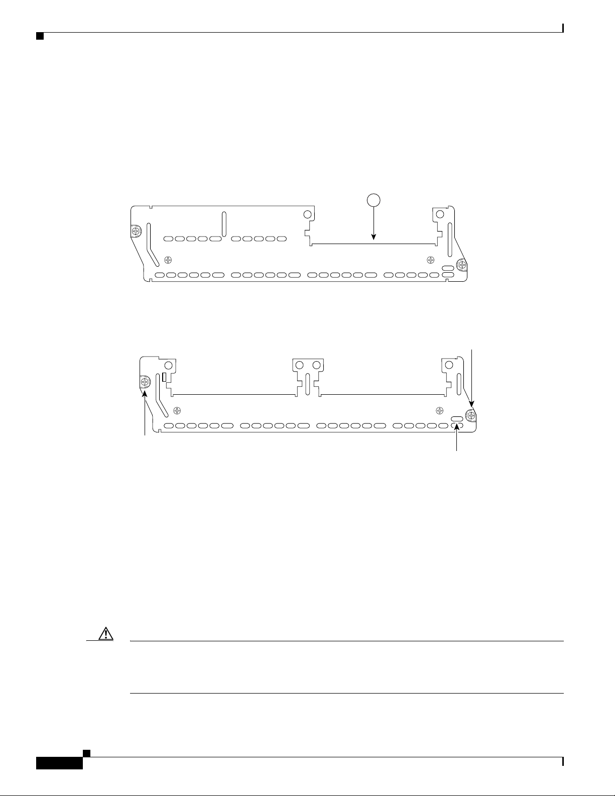
• 1-slot 2-channel voice network module (NM-1V) (see Figure 1)
• 2-slot 4-channel voice network module (NM-2V) (see Figure 2)
Figure 1 1-Slot 2-Channel Voice Network Module (NM-1V)
VOICE
2V
Figure 2 2-Slot 4-Channel Voice Network Module (NM-2V)
VOICE
2V
Module
screw
1
V0V1
EN
H10834
Module
screw
V0V1
EN
H10833
Enable
LED
4-, 8-, and 48-Channel High-Density Voice Network Modules
This section describes the following modules:
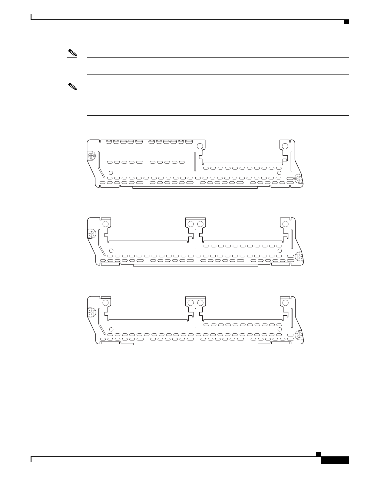
• 1-slot 4-channel high-density voice network module with one digital signal processor (DSP)
(NM-HD-1V) (see Figure 3)
• 2-slot 8-channel high-density voice network module with one DSP (NM-HD-2V) (see Figure 4)
• 2-slot 48-channel high-density enhanced network module with 3 DSPs, supporting up to 8 analog or
48 digital channels (NM-HD-2VE) (see Figure 5)
Caution To comply with the Telcordia GR-1089 NEBS standard for electromagnetic compatibility and safety,
connect the 2-slot 48-channel high-density enhanced network module (NM-HD-2VE) only to
intrabuilding or nonexposed wiring or cabling. The intrabuilding cable must be shielded and the shield
must be grounded at both ends.
Connecting Cisco Voice Network Modules to the Network
2
Page 3
Connecting Cisco Voice Network Modules to the Network
Note For the NM-HD-1V, NM-HD-2V, and NM-DS-2VE network modules, DSPs are on-board and are not
field-replaceable units (FRUs).
Note The NM-HD-1V, NM-HD-2V, and NM-HD-2VE network modules replace the NM-1V and NM-2V
network modules. The NM-1V and NM-2V network modules are still available for use on Cisco 2600
series, Cisco 3600 series, and Cisco 3700 series routers.
Figure 3 1-Slot 4-Channel High-Density Network Module (NM-HD-1V)
NM-HD
-1V
60-Channel High-Density Voice Network Module
V0
EN
89033
Figure 4 2-Slot 8-Channel High-Density Voice Network Module (NM-HD-2V)
NM-HD
-2V
V1
Figure 5 2-Slot 48-Channel High-Density Voice Network Module (NM-HD-2VE)
NM-HD
-2VE
V1
60-Channel High-Density Voice Network Module
V0
EN
89034
V0
EN
89035
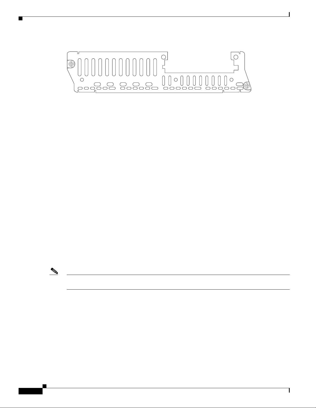
This section describes the 60-channel high-density voice (HDV) network module, shown in Figure 6.
When used in conjunction with T1/E1 multiflex trunk interface cards and packet voice digital signal
processor modules (PVDMs), this module is also called a digital T1/E1 packet voice trunk network
module.
Connecting Cisco Voice Network Modules to the Network
3
Page 4
60-Channel High-Density Voice Network Module
Figure 6 60-Channel High-Density Voice Network Module (NM-HDV)
NM-HDV
BANK 4 BANK 3 BANK 2
The 60-channel HDV network module converts voice and fax into IP packets or frames that can be
transmitted as VoIP over a variety of transport technologies (channelized T1/E1, Frame Relay,
Asynchronous Transfer Mode (ATM), and others). The number of channels supported depends on the
number of PVDMs installed:
• Up to 6 channels per PVDM (30 channels for cards with 5 PVDMs) for high-complexity vocoders
that support the following compression algorithms: G.711, G.726, G.729, G.723.1, G.728, and Fax
Relay
• Up to 12 channels per PVDM (60 channels for cards with 5 PVDMs) for medium-complexity
vocoders that support the following compression algorithms: G.711, G.726, G.729a, and Fax Relay
Both a 60-channel HDV network module and a voice interface card (VIC) are required to connect to the
public switched telephone network (PSTN) or a PBX. One VIC (providing one or two T1/E1 line
interfaces) can be installed in the HDV network module. Currently, only the 1- and 2-port T1/E1
multiflex trunk interface cards (VWIC-1MFT-T1, VWIC-2MFT-T1, and VWIC-2MFT-T1-DI) are
supported using channel-associated signaling (CAS). In Cisco 3620 and Cisco 3640 routers, at least one
other network module or WAN interface card (WIC) must be installed in the router to provide the
connection to the IP LAN or WAN. In Cisco 3660 routers, a network module is required for WAN access
or a direct connection is required for LAN access. In Cisco 2600 series routers, a WIC is required for
WAN access or a direct connection is required for LAN access.
BANK 1
BANK 0
Connecting Cisco Voice Network Modules to the Network
V0
EH
22160
Packet Voice DSP Modules
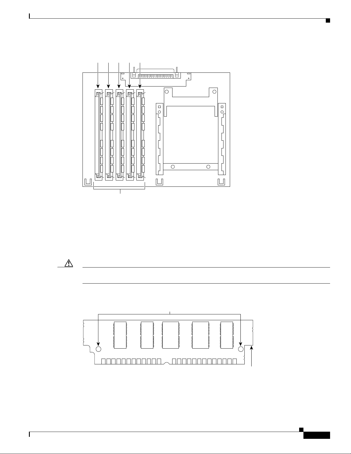
The HDV network module contains five 72-pin SIMM sockets or banks for packet voice DSP modules
(PVDMs), numbered 0 through 4. (See Figure 7.) Each socket can be filled with a single 72-pin PVDM.
The PVDMs must be installed starting from slot 0.
Note PVDM and PVDM2 modules are not interchangeable. Use PVDM modules with the NM-HDV network
module only, and use PVDM2 modules with the NM-HDV2 network module only.
Connecting Cisco Voice Network Modules to the Network
4
Page 5
Connecting Cisco Voice Network Modules to the Network
Figure 7 PVDM Slot Locations
4 3 2 1 0
60-Channel High-Density Voice Network Module
PVDM Orientation
Caution To avoid damaging ESD-sensitive components, observe all ESD precautions. To avoid damaging the
22955
PVDM slots
PVDMs are manufactured with a polarization notch to ensure proper orientation and alignment holes to
ensure proper positioning. Figure 8 shows the polarization notch and alignment holes on a PVDM card.
PVDM cards are installed with the connector edge down, the polarization notch near the front of the
chassis, and the component side facing the right side of the chassis.
HDV network module, avoid using excessive force when you remove or replace PVDMs.
Figure 8 PVDM Orientation
Alignment holes
Connector edge
Polarization notch
Connecting Cisco Voice Network Modules to the Network
22953
5
Page 6
60-Channel High-Density Voice Network Module
Removing PVDMs
To remove PVDMs, follow these steps:
Step 1 Find the PVDM sockets on the HDV network module. (See Figure 7.)
Caution Handle PVDMs by the card edges only. PVDMs are ESD-sensitive components and can be damaged by
mishandling.
Step 2 Remove one PVDM at a time, beginning with the PVDM in bank 4. To lift the PVDM out of its socket,
pull the locking spring clips on both sides outward and tilt the PVDM toward the right side of the chassis,
free of the clips. (See Figure 9.)
Figure 9 Removing PVDMs
Connecting Cisco Voice Network Modules to the Network
Top view
Front of chassis
Step 3
Step 4 Repeat Step 2 and Step 3 for each PVDM.
Installing PVDMs
Step 1 Find the PVDM sockets on the HDV network module. (See Figure 7.)
2. Push the top of the
PVDM forward and down.
23605
1. Pull the locking spring clips outward.
PVDM
polarization
notch
Hold the PVDM by the edges with your thumb and index finger and lift it out of the socket. Place the
removed PVDM in an antistatic bag to protect it from ESD damage.
To install PVDMs, follow these steps:
Caution Handle PVDMs by the card edges only. PVDMs are ESD-sensitive components and can be damaged by
mishandling.
Step 2 Hold the PVDM with the polarization notch on the right, near the front of the chassis, and the component
side away from you, with the connector edge at the bottom. (See Figure 8.)
Connecting Cisco Voice Network Modules to the Network
6
Page 7

Connecting Cisco Voice Network Modules to the Network
Step 3 Beginning with bank 0, insert the PVDM into the connector slot at an angle, tilted toward the right side
of the chassis. Align the PVDM in a vertical position (see Figure 10) by using the minimum amount of
force required. When the PVDM is properly seated, the socket guide posts fit through the alignment
holes, and the connector springs click into place.
Step 4 Ensure that each PVDM is straight and that the alignment holes (as shown in Figure 9) line up with the
plastic guides on the socket.
Figure 10 Installing PVDMs
View from front of board
1. Insert the PVDM into the socket
at an angle from vertical.
2. Push the top of the PVDM
down and back.
The socket guide posts fit through
3.
the holes in the PVDM.
The locking springs clip the back
4.
of the PVDM.
Voice Network Module LEDs
23604
Caution It is normal to feel some resistance, but do not use excessive force on the PVDM and do not touch the
surface components.
Step 5 Repeat Step 2 through Step 4 for each PVDM.
Voice Network Module LEDs
All network modules have an enable (EN) LED. This LED indicates that the module has passed its
self-tests and is available to the router. The following network modules have no additional LEDs. (See
Figure 11 for a sample faceplate.)
• NM-1V
• NM-2V
• NM-HD-1V
• NM-HD-2V
• NM-HD-2VE
Connecting Cisco Voice Network Modules to the Network
7
Page 8

IP Communications High-Density Digital Voice or Fax Network Module
Figure 11 Voice Network Module LED
VOICE
2V
Module
screw
HDV Network Module LEDs
High-density network modules have an enable (EN) LED, and five LEDs for the PVDM banks,
numbered 0 through 4. The enable LED indicates that the module has passed its self-tests and is available
to the router. The BANK 0 through BANK 4 LEDs indicate the current operating condition of the
PVDMs installed on the card. (See Figure 12.) If the BANK LEDs do not come on after initial
installation and configuration, check that the PVDMs are properly seated in their slots.
Connecting Cisco Voice Network Modules to the Network
Module
screw
V0V1
EN
H10833
Enable
LED
Figure 12 HDV Network Module LEDs
NM-HDV
V0
BANK 4 BANK 3 BANK 2
BANK 4
LED
BANK 2
LED
BANK 3
LED
BANK 1
BANK 1
LED
BANK 0
BANK 0
LED
EH
22161
ENABLE
LED
IP Communications High-Density Digital Voice or Fax Network
Module
This section describes the IP communications high-density digital voice or fax (NM-HDV2) network
module. This module is available in three base-board stock-keeping units (SKUs):
• NM-HDV2, with no built-in T1/E1 ports, shown in Figure 13
• NM-HDV2-1T1/E1, with one built-in T1/E1 port, shown in Figure 14
• NM-HDV2-2T1/E1, with two built-in T1/E1 ports, shown in Figure 15
Connecting Cisco Voice Network Modules to the Network
8
Page 9

Connecting Cisco Voice Network Modules to the Network
These three base-board SKUs also include a single VIC or VWIC slot for Foreign Exchange Station
(FXS), Foreign Exchange Office (FXO) or centralized automated message accounting trunk protocol
(CAMA), receive and transmit (E&M), Direct Inward Dial (DID), Basic Rate Interface (BRI), or E1/T1
interface cards.
Figure 13 NM-HDV2
IP Communications High-Density Digital Voice or Fax Network Module
NM-HDV2
PVDM 3
PVDM 2 PVDM 1
Figure 14 NM-HDV2-1T1/E1
NM-HDV2-1T1/E1
PVDM 3
PVDM 2 PVDM 1
Figure 15 NM-HDV2-2T1/E1
NM-HDV2-2T1/E1
AL
PVDM 3
PVDM 2 PVDM 1
LP
CD
CTRLR T1/E1 1
CTRLR T1/E1 0
CTRLR T1/E1 0
See Manual before Installation.
V0
See Manual before Installation.
V0
AL
LP
CD
See Manual before Installation.
V0
AL
LP
CD
PVDM 0
PVDM 0
PVDM 0
EN
95196
EN
95197
EN
95198
The NM-HDV2 network module converts voice and fax into IP packets or frames that can be transmitted
as VoIP over a variety of transport technologies (channelized T1, Frame Relay, Asynchronous Transfer
Mode [ATM], and others).
Packet Fax or Voice DSP Modules
The packet fax or voice digital signal processor (DSP) module (PVDM2) is available in five
stock-keeping units (SKUs):
Table 1 PVDM2 Module SKUs
Module Name Description
PVDM2-8 8-channel packet fax or voice DSP module
PVDM2-16 16-channel packet fax or voice DSP module
Connecting Cisco Voice Network Modules to the Network
9
Page 10

IP Communications High-Density Digital Voice or Fax Network Module
Table 1 PVDM2 Module SKUs
Module Name Description
PVDM2-32 32-channel packet fax or voice DSP module
PVDM2-48 48-channel packet fax or voice DSP module
PVDM2-64 64-channel packet fax or voice DSP module
You can install up to four PVDM2 modules on all of the NM-HDV2 SKUs. The number of channels
supported depends on the number and density-type of PVDM2 modules installed.
Table 2 Channels Per PVDM2 Module Type
Connecting Cisco Voice Network Modules to the Network
Module Name
Max Channels for High
Complexity
1
Max Channels for
Medium Complexity
Range of Channels for
2
Flexi Complexity
3
PVDM2-8444-8
PVDM2-16686-16
PVDM2-32 12 16 12-32
PVDM2-48 18 24 18-48
PVDM2-64 24 32 24-64
1. High-complexity vocoders supported: G.711, G.726, G.729, G.723.1, G.728, and Fax Relay.
2. Medium-complexity vocoders supported: G.711, G.726, G.729a, and Fax Relay.
3. Flexi vocoders supported: G.711, G.726, G.729, G.723.1, G.728, and Fax Relay (number of channels depends on codec
selected).
Note PVDM and PVDM2 modules are not interchangeable. Use PVDM modules with the NM-HDV network
module only, and use PVDM2 modules with the NM-HDV2 network module only.
When used with PVDM2 modules and either the built-in T1/E1 ports or the T1/E1 voice or WAN
interface cards (VWIC), the NM-HDV2 network module provides the interface to the PBX, the PSTN,
or WAN. The following VWICs are supported:
• VWIC-1MFT-T1
• VWIC-2MFT-T1
10
• VWIC-2MFT-T1-DI
• VWIC-1MFT-E1
• VWIC-2MFT-E1
• VWIC-2MFT-E1-DI
• VWIC-1MFT-G703
• VWIC-2MFT-G703
When used with PVDM2 modules and next-generation analog or BRI voice interface cards (VIC2), the
NM-HDV2 network module provides the interface to telephony equipment (PBX, key systems,
telephones, and fax machines) and to the PSTN. The following VICs are supported:
• VIC-2DID
• VIC-1J1
Connecting Cisco Voice Network Modules to the Network
Page 11

Connecting Cisco Voice Network Modules to the Network
IP Communications High-Density Digital Voice or Fax Network Module
• VIC-4FXS/DID (DID feature not supported)
• VIC2-2FXO
• VIC2-4FXO
• VIC2-2FXS
• VIC2-2E/M
• VIC2-2BRI-NT/TE
Configuring E1 Ports for Normal or Wetting Current Mode
On the NM-HDV2-1T1/E1 and NM-HDV2-2T1/E1 network modules there is a jumper block for each
built-in T1/E1 port that controls whether the port supports normal or wetting current mode. Wetting
current is a small amount of electrical current (60 to 140 milliamps) sent from the central office to the
card to prevent the corrosion of electrical contacts in the module’s network connection. Depending on
how your E1 line is provisioned, you might have to change the jumper setting on the network module to
allow proper operation.
The jumper blocks are identified on the printed circuit board of the NM-HDV2-1T1/E1 and
NM-HDV2-2T1/E1 network modules as J6 and J7. (See Figure 16.) J6 is the jumper block for T1/E1
controller 1 and J7 is the jumper block for T1/E1 controller 0. The pins on each jumper block are
numbered 1 to 3 from right to left.
• To configure an E1 port for normal mode, set the jumper to pins 2 and 3.
• To configure an E1 port for wetting current mode, set the jumper to pins 1 and 2.
Figure 16 shows the jumper block configured for normal mode, with the jumper set to pins 2 and 3.
Tip If you are unsure whether your E1 line is configured for normal or wetting current mode, check with
your provider. You can also use the show controllers E1 command to look for line code violations and
path code violations. These errors can indicate that the jumper is not set correctly.
Connecting Cisco Voice Network Modules to the Network
11
Page 12

IP Communications High-Density Digital Voice or Fax Network Module
Figure 16 NM-HDV2-2T1/E1 Jumpers Configured for Normal Mode
J7J6
Connecting Cisco Voice Network Modules to the Network
135658
Installing PVDM2 Modules
The NM-HDV2 network modules contain four 80-pin SIMM sockets for PVDM2 modules, numbered 0
through 3. (See Figure 17.) Each socket can be filled with a single 80-pin PVDM2 module.
Pin 1Pin 2Pin 3
12
Connecting Cisco Voice Network Modules to the Network
Page 13

Connecting Cisco Voice Network Modules to the Network
Figure 17 PVDM2 Module Slot Locations
3 2 1 0
IP Communications High-Density Digital Voice or Fax Network Module
95199
PVDM2 Module Orientation
PVDM2 modules are manufactured with a polarization notch to ensure proper orientation, and alignment
holes to ensure proper positioning. Figure 18 shows the polarization notch and alignment holes on a
PVDM2 module. PVDM2 modules are installed with the connector edge down, the polarization notch
near the back of the chassis.
Caution To avoid damaging ESD-sensitive components, observe all ESD precautions. To avoid damaging the
NM-HDV2 network module, avoid using excessive force when you remove or replace PVDM2 modules.
Figure 18 PVDM2 Module Orientation
Connector edge
Alignment holes
95200
Polarization notch
Alignment notch
Connecting Cisco Voice Network Modules to the Network
13
Page 14

IP Communications High-Density Digital Voice or Fax Network Module
Removing PVDM2 Modules
To remove PVDM2 modules, follow these steps:
Step 1 Find the PVDM2 sockets on the NM-HDV2 network module. (See Figure 17.)
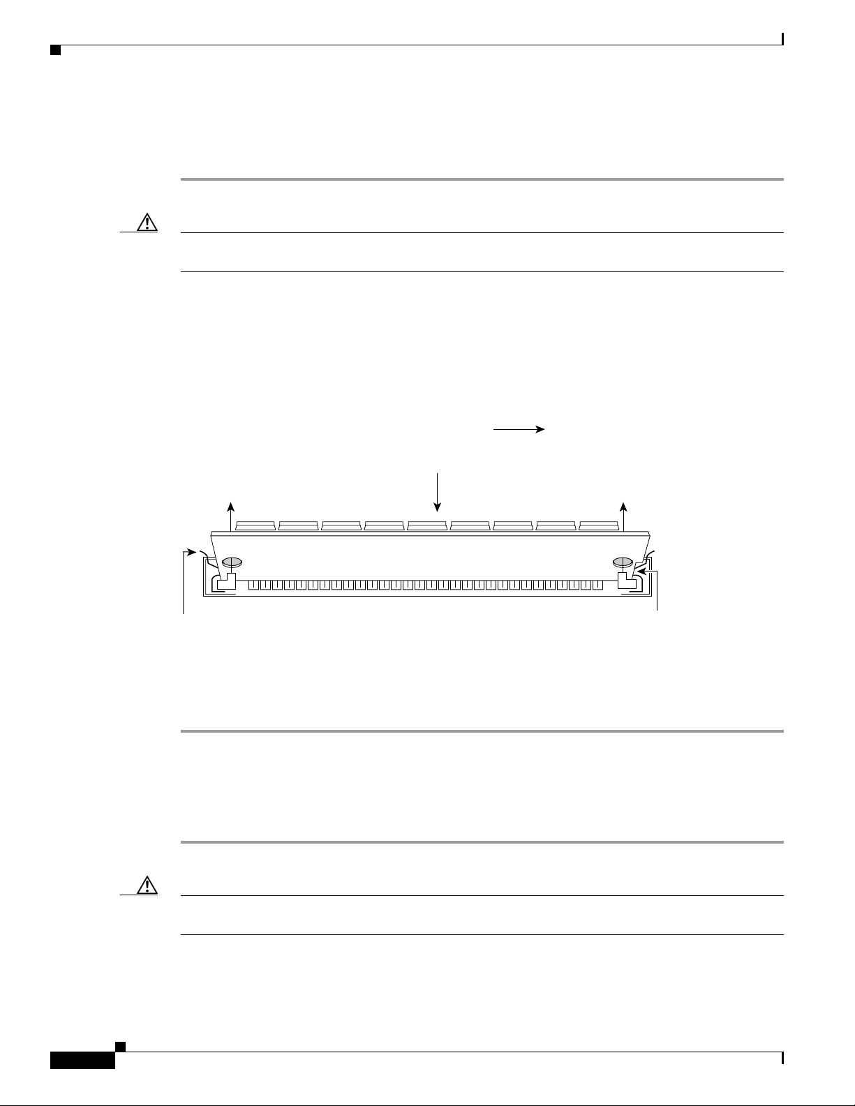
Caution Handle PVDM2 modules by the card edges only. PVDM2 modules are ESD-sensitive components and
can be damaged by mishandling.
Step 2 Remove one PVDM2 module at a time. To make your job easier, if you have a PVDM2 module in both
socket 0 and socket 1, remove PVDM 1 before removing PVDM 0. Similarly, remove PVDM 3 before
removing PVDM 2. To lift the PVDM2 module out of its socket, pull the locking spring clips on both
sides outward and tilt the PVDM2 module toward the left side of the chassis, free of the clips. (See
Figure 19.)
Figure 19 Removing PVDM2 Modules
Connecting Cisco Voice Network Modules to the Network
Top view
1. Pull the locking spring clips outward.
Step 3
Hold the PVDM2 module by the edges with your thumb and index finger and lift it out of the socket.
Place the removed PVDM2 module in an antistatic bag to protect it from ESD damage.
Step 4 Repeat Step 2 and Step 3 for each PVDM2 module.
Installing PVDM2 Modules
To install PVDM2 modules, follow these steps:
Front of chassis
2. Push the top of the
PVDM forward and down.
95201
PVDM
polarization
notch
14
Step 1 Find the PVDM2 sockets on the NM-HDV2 network module. (See Figure 17.)
Caution Handle PVDM2 modules by the card edges only. PVDM2 modules are ESD-sensitive components and
can be damaged by mishandling.
Connecting Cisco Voice Network Modules to the Network
Page 15

Connecting Cisco Voice Network Modules to the Network
Step 2 Hold the PVDM2 module with the polarization notch on the right, near the back of the chassis, with the
connector edge at the bottom. (See Figure 18.)
Step 3 Again, to make your job easier, begin with socket 0, then socket 1, or socket 2, then socket 3. Insert the
PVDM2 module into the connector slot at an angle, tilted toward the left side of the chassis. Align the
PVDM2 module in a vertical position (see Figure 20), by using the minimum amount of force required.
When the PVDM2 module is properly seated, the socket guide posts fit through the alignment holes, and
the connector springs click into place.
Step 4 Ensure that each PVDM2 module is straight and that the alignment holes (as shown in Figure 19) line
up with the plastic guides on the socket.
Note Be sure to align the alignment notch in the bottom of the PVDM2 module with the rib in the
80-pin socket.
Figure 20 Installing PVDM2 Modules
View from front of board
IP Communications High-Density Digital Voice or Fax Network Module
1. Insert the PVDM2 into the socket
2. Push the top of the PVDM2
3.
4.
103280
Caution It is normal to feel some resistance, but do not use excessive force on the PVDM2 module, and do not
touch the surface components.
Step 5 Repeat Step 2 through Step 4 for each PVDM2 module.
NM-HDV2 Network Module LEDs
IP communications high-density digital voice or fax (NM-HDV2) network modules have an enable (EN)
LED, and four LEDs for the PVDM2 modules, numbered 0 through 3. The enable LED indicates that the
module has passed its self-tests and is available to the router. The PVDM 0 through PVDM 3 LEDs
indicate the current operating condition of the PVDM2 modules installed on the card. (See Figure 21.)
If the PVDM LEDs are not green after initial installation and configuration, check that the PVDM2
modules are properly seated in their slots.
at an angle from vertical.
down and back.
The socket guide posts fit through
the holes in the PVDM2.
The locking springs clip the back
of the PVDM2.
Connecting Cisco Voice Network Modules to the Network
15
Page 16

Related Documents
Connecting Cisco Voice Network Modules to the Network
Figure 21 NM-HDV2 Network Module LEDs
NM-HDV2
PVDM 3
PVDM 2 PVDM 1
PVDM 3
PVDM 2
LED
LED
See Manual before Installation.
V0
PVDM 1
LED
PVDM 0
PVDM 0
ENABLE
EN
103881
LED
LED
The NM-HDV2-1T1/E1 and NM-HDV2-2T1/E1 network modules have LEDs monitoring the alarm
(AL), loopback (LP), and carrier detection (CD) conditions of the built-in T1/E1 ports. (See Figure 22.)
Figure 22 NM-HDV2-2T1/E1 LEDs
NM-HDV2-2T1/E1
PVDM 3
PVDM 3
LED
AL
PVDM 2 PVDM 1
LP
CD
CTRLR T1/E1 1
CTRLR T1/E1 0
PVDM 2
LED
Alarm,
loopback, and
carrier detect
LEDs
See Manual before Installation.
V0
AL
LP
CD
PVDM 1
Alarm,
loopback, and
carrier detect
LEDs
LED
PVDM 0
ENABLE
PVDM 0
LED
EN
95203
LED
Related Documents
For additional information, see the following documents and resources.
Related Topic Document Title
Regulatory compliance and safety
information
Cisco IOS software website and reference
documentation
Connecting Cisco Voice Network Modules to the Network
16
Cisco Network Modules and Interface Cards Regulatory Compliance and Safety
Information
http://www.cisco.com/en/US/docs/routers/access/interfaces/rcsi/IOHrcsi.html
Cisco IOS Software
http://www.cisco.com/web/psa/products/index.html?c=268438303
Page 17

Connecting Cisco Voice Network Modules to the Network
Obtaining Documentation, Obtaining Support, and Security Guidelines
Obtaining Documentation, Obtaining Support, and Security
Guidelines
For information on obtaining documentation, obtaining support, providing documentation feedback,
security guidelines, and also recommended aliases and general Cisco documents, see the monthly
What’s New in Cisco Product Documentation, which also lists all new and revised Cisco technical
documentation, at:
http://www.cisco.com/en/US/docs/general/whatsnew/whatsnew.html
CCDE, CCENT, Cisco Eos, Cisco Lumin, Cisco StadiumVision, the Cisco logo, DCE, and Welcome to the Human Network are trademarks;
Changing the Way We Work, Live, Play, and Learn is a service mark; and Access Registrar, Aironet, AsyncOS, Bringing the Meeting To You,
Catalyst, CCDA, CCDP, CCIE, CCIP, CCNA, CCNP, CCSP, CCVP, Cisco, the Cisco Certified Internetwork Expert logo, Cisco IOS, Cisco Press,
Cisco Systems, Cisco Systems Capital, the Cisco Systems logo, Cisco Unity, Collaboration Without Limitation, EtherFast, EtherSwitch, Event
Center, Fast Step, Follow Me Browsing, FormShare, GigaDrive, HomeLink, Internet Quotient, IOS, iPhone, iQ Expertise, the iQ logo, iQ Net
Readiness Scorecard, iQuick Study, IronPort, the IronPort logo, LightStream, Linksys, MediaTone, MeetingPlace, MGX, Networkers, Networking
Academy, Network Registrar, PCNow, PIX, PowerPanels, ProConnect, ScriptShare, SenderBase, SMARTnet, Spectrum Expert, StackWise, The
Fastest Way to Increase Your Internet Quotient, TransPath, WebEx, and the WebEx logo are registered trademarks of Cisco Systems, Inc. and/or its
affiliates in the United States and certain other countries.
All other trademarks mentioned in this document or Website are the property of their respective owners. The use of the word partner does not imply
a partnership relationship between Cisco and any other company. (0804R)
Any Internet Protocol (IP) addresses used in this document are not intended to be actual addresses. Any examples, command display output, and
figures included in the document are shown for illustrative purposes only. Any use of actual IP addresses in illustrative content is unintentional and
coincidental.
© 2008 Cisco Systems, Inc. All rights reserved.
Connecting Cisco Voice Network Modules to the Network
17
Page 18

Obtaining Documentation, Obtaining Support, and Security Guidelines
Connecting Cisco Voice Network Modules to the Network
18
Connecting Cisco Voice Network Modules to the Network
 Loading...