

Page 1

Connecting Cisco ISDN PRI Network Modules to
the Network
Revised: May 1, 2008, OL-12811-01
This guide describes how to connect Cisco Integrated Services Digital Network (ISDN) Primary Rate
Interface (PRI) network modules to your network. It contains the following sections:
• Channelized T1/E1 PRI Network Modules with G.703, page 2
• Channelized T1/ISDN PRI Network Modules, page 5
• Channelized T1/ISDN PRI with CSU Network Modules, page 6
• Channelized E1/ISDN PRI Balanced (120-Ohm) Network Modules, page 7
• Channelized E1/ISDN PRI Unbalanced (75-Ohm) Network Modules, page 10
• PRI Module LEDs, page 11
• Online Insertion and Removal with a Cisco PRI Network Module (Cisco 3660 and Cisco 3745
Only), page 14
• Upgrading ISDN PRI Network Modules, page 15
• Related Documents, page 15
• Obtaining Documentation, Obtaining Support, and Security Guidelines, page 16
Note Unless specifically identified, references to PRI modules in this chapter include all these network
modules.
Note Do not install an ISDN BRI network module in the same chassis as an ISDN PRI network module, unless
you are using Cisco IOS Release 11.3(3)T or later. Earlier Cisco IOS releases do not support this
configuration.
CT1/PRI modules are available with or without a built-in channel service unit (CSU), and with one or
two ports. CT1/PRI modules connect to an external CSU; CT1/PRI-CSU modules connect directly to the
network. Each T1 module provides up to 24 virtual channels per T1 port. Each channel can be configured
individually as a serial interface.
Americas Headquarters:
Cisco Systems, Inc., 170 West Tasman Drive, San Jose, CA 95134-1706 USA
Page 2

Connecting Cisco ISDN PRI Network Modules to the Network
Channelized T1/E1 PRI Network Modules with G.703
CT1/PRI and CT1/PRI-CSU modules receive and transmit data bidirectionally, at the T1 rate of
1.544 Mbps.
Channelized T1/E1 PRI Network Modules with G.703
This section provides information about the following network modules:
• 1-port T1/E1 channelized PRI network module with G.703 (NM-1CE1T1-PRI) (see Figure 1)
• 2-port T1/E1 channelized PRI network module with G.703 (NM-2CE1T1-PRI) (see Figure 2)
Cisco T1/E1 channelized PRI network modules with G.703 provide connection of one or two primary
rate ISDN lines. T1 or E1 interfaces are configurable through Cisco IOS command-line interface (CLI)
commands. Each port supports 100/120-ohm balanced and 75-ohm unbalanced termination, and features
RJ-48C connectors and cable accessories allowing for DB-15, BNC, and other connector types. An
onboard advanced integration module (AIM) connector allows for future universal port AIM support.
Caution To comply with the Telcordia GR-1089 NEBS standard for electromagnetic compatibility and safety,
connect the 1-port T1/E1 channelized PRI network modules with G.703 (NM-1CE1T1-PRI) and 2-port
T1/E1 channelized PRI network modules with G.703 (NM-2CE1T1-PRI) only to intrabuilding or
nonexposed wiring or cabling. The intrabuilding cable must be shielded and the shield must be grounded
at both ends.
Cisco T1/E1 channelized PRI network modules with G.703 (NM-1CE1T1-PRI and NM-2CE1T1-PRI)
replace the following network modules (also described in this chapter):
• NM-1CE1B
• NM-1CE1U
• NM-1CT1
• NM-1CT1-CSU
• NM-2CE1B
• NM-2CE1U
• NM-2CT1
• NM-2CT1-CSU
For information on Cisco modular access routers supporting Cisco channelized T1/E1 PRI network
modules with G.703, see Tab le 1.
Table 1 Modular Access Routers Supporting Cisco Channelized T1/E1 PRI Network Modules
with G.703
Modular Access Router NM-1CE1T1-PRI NM-2CE1T1-PRI
Cisco 26xx No No
Cisco 26xxXM Yes Yes
Cisco 2691 Yes Yes
Cisco 3620 No No
Cisco 3631 Yes Yes
Cisco 3640 No No
Connecting Cisco ISDN PRI Network Modules to the Network
2
Page 3
Connecting Cisco ISDN PRI Network Modules to the Network
Table 1 Modular Access Routers Supporting Cisco Channelized T1/E1 PRI Network Modules
with G.703
Modular Access Router NM-1CE1T1-PRI NM-2CE1T1-PRI
Cisco 3660 Yes Yes
Cisco 37xx Yes Yes
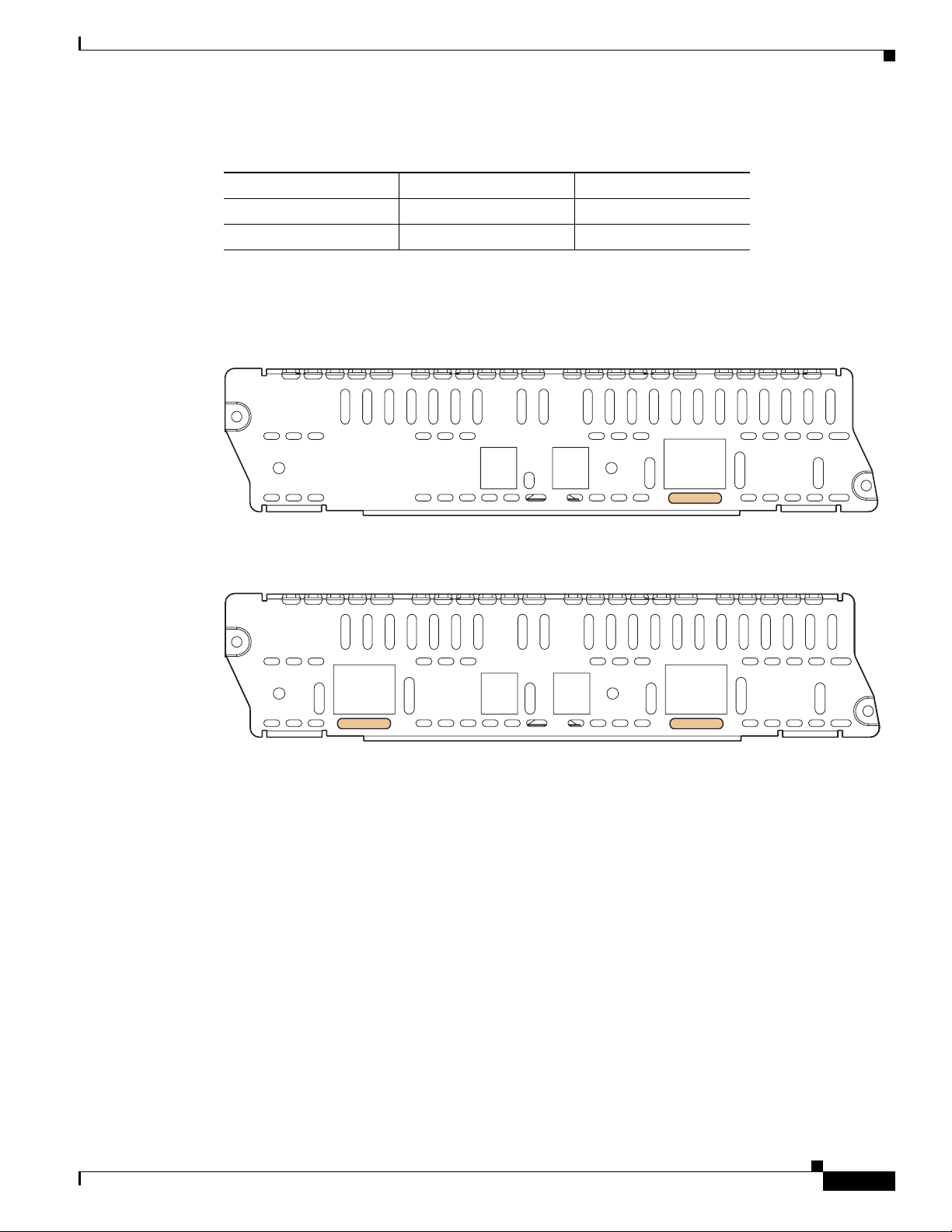
Figure 1 and Figure 2 show the faceplates for the 1-port and 2-port channelized T1/E1 PRI network
modules with G.703.
Figure 1 1-Port Channelized T1/E1 PRI Network Module with G.703
NM-1CE1T1-PRI
Channelized T1/E1 PRI Network Modules with G.703
MON
RX
TX
MON
CD
RA
LAC0
CTLR 0
LP
T1
E1-BAL
E1-UNBAL
AIM
EN
Figure 2 2-Port Channelized T1/E1 PRI Network Module with G.703
NM-2CE1T1-PRI
CD
RA
LA
CTLR 1
LP
T1
E1-BAL
E1-UNBAL
RX
MON
TX
MON
C1
C0
CD
RA
LA
CTLR 0
LP
T1
E1-BAL
E1-UNBAL
AIM
EN
Enabling Wetting Current on Channelized T1/E1 PRI Network Modules with G.703
Wetting current is a small amount of electrical current (60 to 140 milliamps) sent from the central office
to the card to prevent the corrosion of electrical contacts in the module network connection.
82886
82887
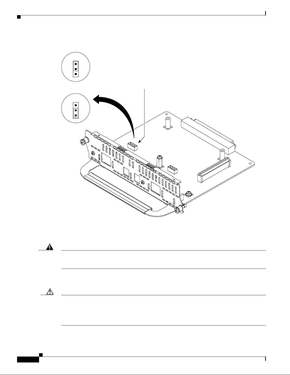
The wetting current feature can be enabled or disabled by the end user. It is controlled by the location of
a jumper on the J8 (CTLR 0) and J9 (CTLR 1) connectors on the network module. (See Figure 3.)
To enable the wetting current feature, connect pins 1 and 2 on the J8 and J9 connectors with the jumper.
To disable the wetting current feature, either remove the jumper completely, or use the jumper to connect
pins 2 and 3 on the J8 and J9 connectors.
The card is shipped with the jumper connecting pins 2 and 3 on the J8 and J9 connectors, disabling the
wetting current feature.
Connecting Cisco ISDN PRI Network Modules to the Network
3
Page 4
Channelized T1/E1 PRI Network Modules with G.703
Figure 3 Wetting Current Jumper Locations on Channelized T1/E1 PRI Network Modules with
G.703
J8/J9
1
2
3
Wetting current
enabled
J8/J9
1
2
3
Wetting current
disabled
NM-2CE1T1-PRI
RA
LA
CD
CTLR 1
Connecting Cisco ISDN PRI Network Modules to the Network
Wetting current
jumper
3
2
1
LP
T1
E1-B
E1-UNB
J9
RX
MON
TX
MON
C1
C0
CD
RA
LA
CTLR 0
3
2
1
J8
LP
T1
E1-B
E1-UNB
AIM
EN
88539
Connecting Channelized T1/E1 PRI Network Modules with G.703 to a Network
Warning
Caution To comply with the Telcordia GR-1089 NEBS standard for electromagnetic compatibility and safety,
Connecting Cisco ISDN PRI Network Modules to the Network
4
For connections outside the building where the equipment is installed, the following ports must be
connected through an approved network termination unit with integral circuit protection: T1
Statement 1044
Figure 4 shows a connection between a channelized T1/E1 PRI network module with G.703 and a
networking device.
connect the 1-port T1/E1 channelized PRI network modules with G.703 (NM-1CE1T1-PRI) and 2-port
T1/E1 channelized PRI network modules with G.703 (NM-2CE1T1-PRI) only to intrabuilding or
nonexposed wiring or cabling. The intrabuilding cable must be shielded and the shield must be grounded
at both ends.
Page 5
Connecting Cisco ISDN PRI Network Modules to the Network
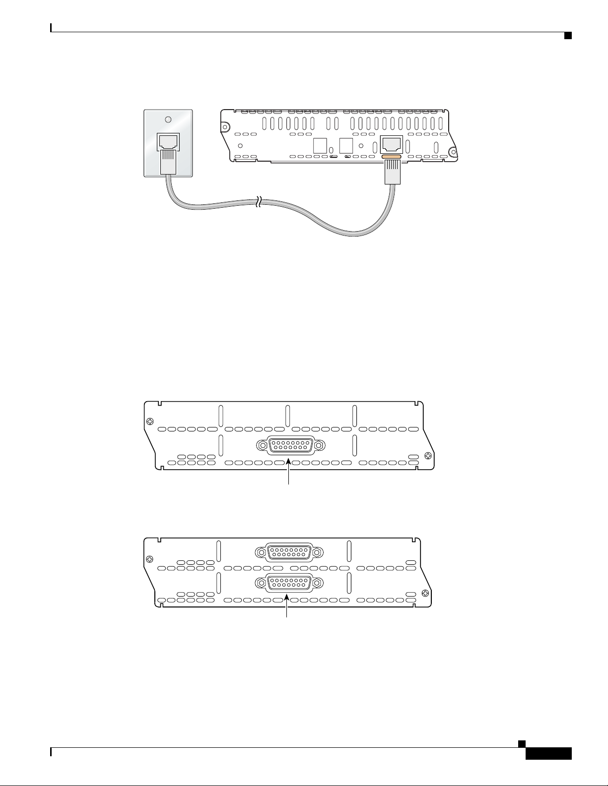
Figure 4 Connecting a Channelized T1/E1 PRI Network Module with G.703 to a Networking
Device
NM-1CE1T1-PRI
RX
TX
MON
MON
CD
LP
RA
LAC0
CTLR 0
Channelized T1/ISDN PRI Network Modules
This section provides information about the following network modules for Cisco modular routers:
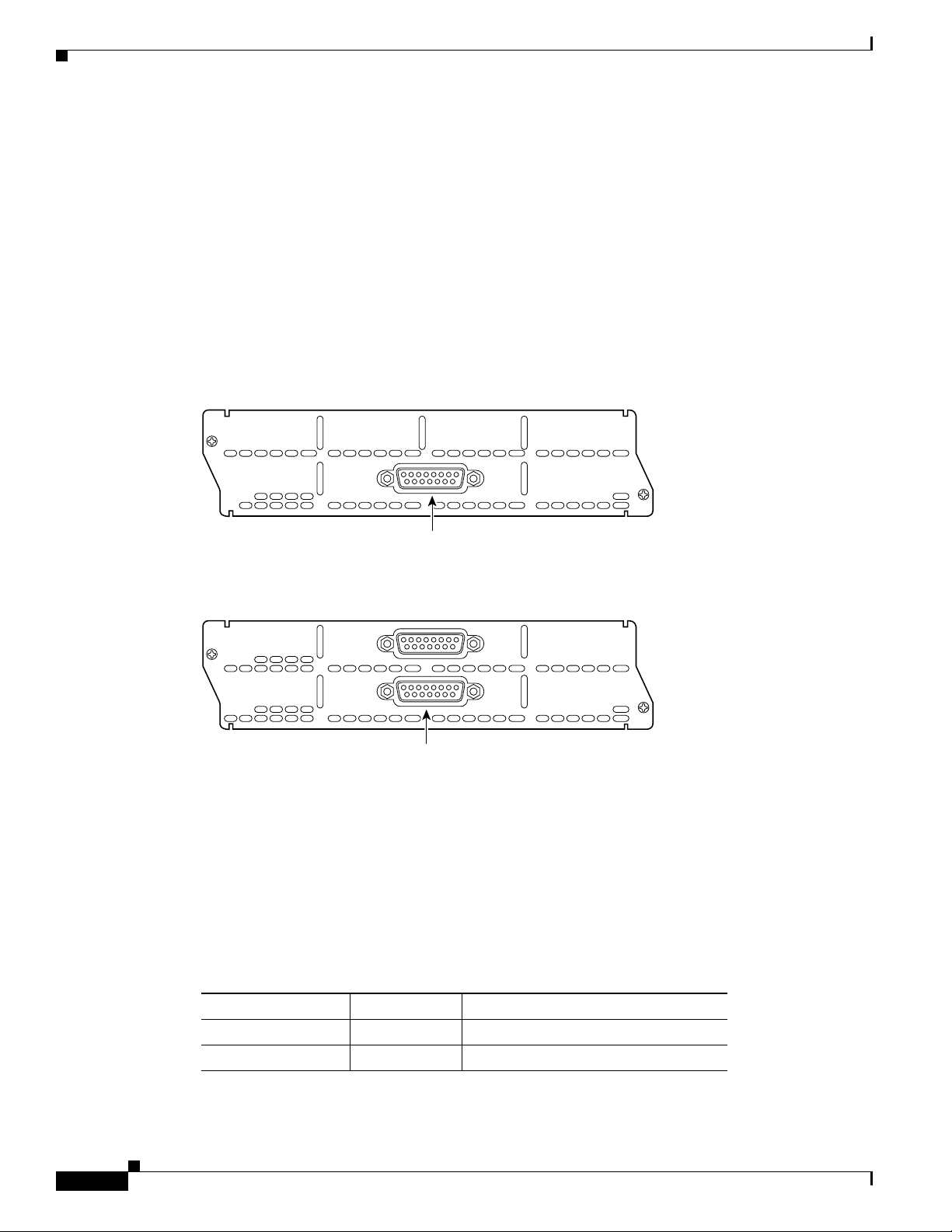
• 1-port channelized T1/ISDN PRI network module (NM-1CT1 or CPANM-1CT1) (see Figure 5).
This module is also referred to as the 1-port CT1/PRI network module.
Channelized T1/ISDN PRI Network Modules
T1
AIM
E1-BAL
EN
E1-UNBAL
88639
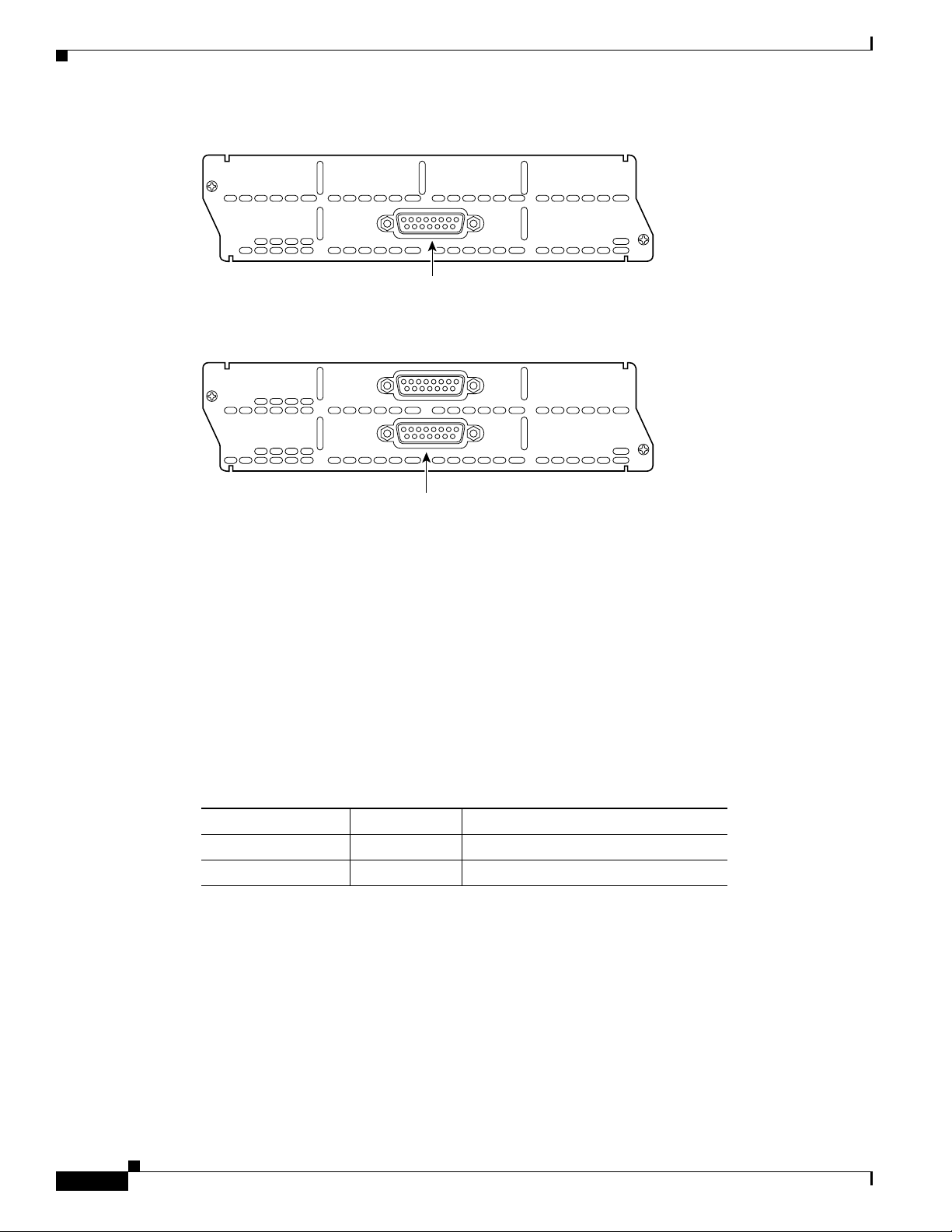
• 2-port channelized T1/ISDN PRI network module (NM-2CT1 or CPANM-2CT1) (see Figure 6).
This module is also referred to as the 2-port CT1/PRI network module.
Figure 5 1-Port Channelized T1/ISDN PRI Network Module
cT1
PRI
CARRIER
DETECT
LOOPBACK
LOCAL
ALARM
REMOTE
ALARM
CTRLR 0
CT1/PRI-U port (DB-15)
Figure 6 2-Port Channelized T1/ISDN PRI Network Module
cT1
PRI
REMOTE
ALARM
REMOTE
ALARM
LOCAL
ALARM
LOCAL
ALARM
CARRIER
DETECT
LOOPBACK
CARRIER
DETECT
LOOPBACK
CTRLR 1
CTRLR 0
CT1/PRI-U ports (DB-15)
EN
H7460
EN
EN
H7461
Connecting CT1/PRI Modules to the Network
To connect a CT1/PRI module to the network, use a DB-15-to-DB-15 T1 serial cable to connect the
CT1/PRI port to a T1 channel service unit (CSU). (See Figure 7.) These ports are color-coded tan.
Connecting Cisco ISDN PRI Network Modules to the Network
5
Page 6

Channelized T1/ISDN PRI with CSU Network Modules
Figure 7 Connecting a CT1/PRI Module to a T1 CSU
FE–PRI
1FE-1CT1
REMOTE
CTRLR 0
ALARM
LOCAL
ALARM
LOOP
CARRIER
BACK
DETECT
CT1/PRI port (DB-15)
Connecting Cisco ISDN PRI Network Modules to the Network
10/100BaseT
COLL
LINK
100Mbps
FDX
EN
T1 serial
cable
H7468
T1 CSU
CT1/PRI port (DB-15)
Channelized T1/ISDN PRI with CSU Network Modules
This section provides information about the following network modules for Cisco modular routers:
• 1-port channelized T1/ISDN PRI with CSU network module (NM-1CT1-CSU or
CPANM-1CT1-CSU) (see Figure 8). This module is also referred to as the 1-port CT1/PRI CSU
network module.
• 2-port channelized T1/ISDN PRI with CSU network module (NM-2CT1-CSU or
CPANM-2CT1-CSU) (see Figure 9). This module is also referred to as the 2-port CT1/PRI CSU
network module.
Figure 8 1-Port Channelized T1/ISDN PRI with CSU Network Module
cT1
CSU
RX
OUT
RX
TX
MON
IN
REMOTE
ALARM
LOCAL
ALARM
CARRIER
LOOPBACK
DETECT
CTRLR 0
EN
H7465
Monitor and
test ports
CT1/PRI CSU
port (RJ-48)
(Bantam)
Connecting Cisco ISDN PRI Network Modules to the Network
6
Page 7

Connecting Cisco ISDN PRI Network Modules to the Network
Figure 9 2-Port Channelized T1/ISDN PRI with CSU Network Module
cT1
CSU
REMOTE
ALARM
LOCAL
ALARM
CARRIER
LOOPBACK
DETECT
RX
TX
OUT
IN
Channelized E1/ISDN PRI Balanced (120-Ohm) Network Modules
RX
MON
CTRLR 1
CARRIER
DETECT
LOOPBACK
LOCAL
ALARM
REMOTE
ALARM
Monitor and
test ports
CT1/PRI CSU
port (RJ-48)
CTRLR 0
(Bantam)
Connecting CT1/PRI CSU Modules to the Network
To connect a CT1/PRI CSU module to the network, use a straight-through RJ-48C-to-RJ-48C cable to
connect the RJ-48C port to an RJ-48C jack (see Figure 10). These ports are color-coded tan.
Figure 10 Connecting a CT1/PRI CSU Module to an RJ-48C Jack
FE–PRI
1FE-1CT1-CSU
REMOTE
ALARM
LOCAL
ALARM
LOOP
CARRIER
BACK
DETECT
CTRLR 0
CT1/PRI CSU
port (RJ-48C)
10/100BaseT
COLL
LINK
100Mbps
FDX
EN
EN
H7464
H7469
RJ-48C jack
Channelized E1/ISDN PRI Balanced (120-Ohm) Network
Modules
This section provides information about the following network modules for Cisco modular routers:
• 1-port channelized E1/ISDN PRI balanced (120-ohm) network module (NM-1CE1B or
CPANM-1CE1B) (see Figure 11). This module is also referred to as the 1-port CE1/PRI-B network
module.
• 2-port channelized E1/ISDN PRI balanced (120-ohm) network module (NM-2CE1B or
CPANM-2CE1B) (see Figure 12). This module is also referred to as the 2-port CE1/PRI-B network
module.
Connecting Cisco ISDN PRI Network Modules to the Network
7
Page 8
Channelized E1/ISDN PRI Balanced (120-Ohm) Network Modules
Figure 11 1-Port Channelized E1/ISDN PRI Network Module (Balanced)
cE1-B
PRI
Connecting Cisco ISDN PRI Network Modules to the Network
CARRIER
DETECT
LOOPBACK
LOCAL
ALARM
REMOTE
ALARM
CTRLR 0
Figure 12 2-Port Channelized E1/ISDN PRI Network Module (Balanced)
cE1-B
PRI
REMOTE
ALARM
REMOTE
ALARM
LOCAL
ALARM
LOCAL
ALARM
CARRIER
LOOPBACK
CARRIER
LOOPBACK
DETECT
DETECT
CTRLR 1
CTRLR 0
CE1/PRI-B ports
CE1/PRI modules are available with one or two E1 ports and with balanced or unbalanced interfaces.
These modules receive and transmit data bidirectionally at the E1 rate of 2.048 Mbps, and provide up to
30 virtual channels per E1 port. Each channel can be configured individually as a serial interface.
CE1/PRI Module Jumper Settings
Jumpers on CE1/PRI modules can be used to connect or disconnect receive shield to ground. (See
Table 2.) The default setting for balanced, 120-ohm CE1/PRI-B modules disconnects receive shield to
ground. The default setting for unbalanced, 75-ohm CE1/PRI-U modules connects receive shield to
ground. If you are experiencing ground loop problems with E1 cabling, you may want to try changing
the jumper settings for the module.
EN
H7260
CE1/PRI-B port
EN
H7261
Table 2 CE1/PRI Module Jumpers
CE1/PRI Module Type Default Setting Function
Balanced, 120-ohm 2 and 3 Disconnects receive shield from ground
Unbalanced, 75-ohm 1 and 2 Connects receive shield to ground
Connecting CE1/PRI-B Modules to the Network
To connect a CE1/PRI-B (120-ohm) module to the network, use the appropriate cable to connect the
CE1/PRI-B port to an E1 CSU. (See Figure 13, Figure 14, and Figure 15, showing DB-15, twinax, and
RJ-45 CSUs, respectively.) These ports are color-coded tan.
Connecting Cisco ISDN PRI Network Modules to the Network
8
Page 9

Connecting Cisco ISDN PRI Network Modules to the Network
Figure 13 Connecting a 120-ohm CE1/PRI-B Module to an E1 CSU (DB-15-to-DB-15 Connectors)
FE-PRI
1FE-1CE1-B/U
ALARM
CTRLR 0
LOCAL
ALARM
LOOP
CARRIER
BACK
DETECT
REMOTE
CE1/PRI-B (DB-15)
E1 cable for 120-ohm
balanced connections
with a DB-15 connector
at the network end
Figure 14 Connecting a 120-ohm CE1/PRI-B Module to an E1 CSU (DB-15-to-Twinax Connectors)
FE-PRI
1FE-1CE1-B/U
CTRLR 0
REMOTE
ALARM
LOCAL
ALARM
LOOP
CARRIER
BACK
DETECT
10/100BaseT
COLL
LINK
100Mbps
FDX
DB-15 connector
COLL
LINK
100Mbps
FDX
Channelized E1/ISDN PRI Balanced (120-Ohm) Network Modules
EN
H7470
E1 CSU
10/100BaseT
EN
CE1/PRI port (DB-15)
E1 cable for 75-ohm
balanced connections
H7473
with twinax connectors
at the network end
E1 CSU
Twinax connectors
Figure 15 Connecting a 120-ohm CE1/PRI-B Module to an E1 CSU (DB-15-to-RJ-45 Connectors)
FE-PRI
1FE-1CE1-B/U
ALARM
CTRLR 0
LOCAL
ALARM
LOOP
CARRIER
BACK
DETECT
REMOTE
CE1/PRI port (DB-15)
E1 cable for 120-ohm
balanced connections
with an RJ-45 connector
at the network end
10/100BaseT
COLL
LINK
100Mbps
FDX
EN
H7472
RJ-45 jack
Connecting Cisco ISDN PRI Network Modules to the Network
9
Page 10
Connecting Cisco ISDN PRI Network Modules to the Network
Channelized E1/ISDN PRI Unbalanced (75-Ohm) Network Modules
Channelized E1/ISDN PRI Unbalanced (75-Ohm) Network
Modules
This section provides information about the following network modules for Cisco modular routers:
• 1-port channelized E1/ISDN PRI unbalanced (75-ohm) network module (NM-1CE1U or
CPANM-1CE1U) (see Figure 16). This module is also referred to as the 1-port CE1/PRI-U network
module.
• 2-port channelized E1/ISDN PRI unbalanced (75-ohm) network module (NM-2CE1U or
CPANM-2CE1U) (see Figure 17). This module is also referred to as the 2-port CE1/PRI-U network
module.
Figure 16 1-Port Channelized E1/ISDN PRI Network Module (Unbalanced)
cE1-U
PRI
CARRIER
DETECT
LOOPBACK
LOCAL
ALARM
REMOTE
ALARM
CTRLR 0
Figure 17 2-Port Channelized E1/ISDN PRI Network Module (Unbalanced)
cE1-U
PRI
REMOTE
ALARM
REMOTE
ALARM
LOCAL
ALARM
LOCAL
ALARM
CARRIER
LOOPBACK
CARRIER
LOOPBACK
DETECT
DETECT
CTRLR 1
CTRLR 0
CE1/PRI-U ports
CE1/PRI Module Jumper Settings
Jumpers on CE1/PRI modules can be used to connect or disconnect receive shield to ground (see
Table 3). The default setting for balanced, 120-ohm CE1/PRI-B modules disconnects receive shield to
ground. The default setting for unbalanced, 75-ohm CE1/PRI-U modules connects receive shield to
ground. If you are experiencing ground loop problems with E1 cabling, you may want to try changing
the jumper settings for the module.
EN
H8499
CE1/PRI-U port
EN
H8500
10
Table 3 CE1/PRI Module Jumpers
CE1/PRI Module Type Default Setting Function
Balanced, 120-ohm 2 and 3 Disconnects receive shield from ground
Unbalanced, 75-ohm 1 and 2 Connects receive shield to ground
Connecting Cisco ISDN PRI Network Modules to the Network
Page 11

Connecting Cisco ISDN PRI Network Modules to the Network
Connecting CE1/PRI-U Modules to the Network
To connect a CE1/PRI-U (75-ohm) module to the network, use the appropriate cable to connect the
CE1/PRI-U port to an E1 CSU (see Figure 18). These ports are color-coded tan. The illustration shows
a CSU with BNC connectors.
Figure 18 Connecting a CE1/PRI-U Module to an E1 CSU
(DB-15-to-BNC Connectors)
FE-PRI
1FE-1CE1-B/U
ALARM
CTRLR 0
LOCAL
ALARM
LOOP
CARRIER
BACK
DETECT
REMOTE
CE1/PRI-U
E1 cable for 75-ohm
unbalanced connections
with BNC connectors
at the network end
10/100BaseT
COLL
LINK
100Mbps
FDX
EN
PRI Module LEDs
H7471
E1 CSU
BNC connectors
PRI Module LEDs
All network modules have an enable (EN) LED. This LED indicates that the module has passed its
self-tests and is available to the router.
All PRI modules display four additional LEDs for each port. These LEDs are described in Tab le 4.
Table 4 ISDN PRI Network Module LEDs
LED Meaning
RA Local alarm at remote end of connection
LA Loss of signal, loss of frame, or unavailability because of
excessive errors
LP Loopback mode
CD Carrier received on telco link
Channelized T1/E1 PRI Network Module with G.703 LEDs
Figure 19 and Figure 20 show channelized T1/E1 PRI network module with G.703 LEDs. See Table 5
for LED definitions.
For LEDs found on all PRI network modules, see Table 4.
Connecting Cisco ISDN PRI Network Modules to the Network
11
Page 12

PRI Module LEDs
Connecting Cisco ISDN PRI Network Modules to the Network
Figure 19 1-Port Channelized T1/E1 PRI Network Module with G.703 LEDs
NM-1CE1T1-PRI
MON
RX
MON
TX
CD
RA
LAC0
CTLR 0
LP
T1
E1-BAL
E1-UNBAL
C0
Figure 20 2-Port Channelized T1/E1 PRI Network Module with G.703 LEDs
NM-2CE1T1-PRI
CD
RA
LA
CTLR 1
LP
T1
E1-BAL
E1-UNBAL
MON
RX
TX
MON
C1
C0
CD
RA
LA
CTLR 0
LP
T1
E1-BAL
E1-UNBAL
T1
E1-BAL
E1-UNBAL
CTRL 1
CTRL 0
Table 5 Channelized T1/E1 PRI Network Module with G.703 LEDs
AIM
EN
88737
T1
E1-BAL
E1-UNBAL
AIM
EN
88738
T1
E1-BAL
E1-UNBAL
LED Color Meaning
T1 Green Interface is configured for balanced T1.
E1-BAL Green Interface is configured for balanced E1.
E1-UNBAL Green Interface is configured for unbalanced E1.
C0 Green Port 0 is connected to the bantam monitor connector.
C1 Green Port 1 is connected to the bantam monitor connector.
AIM Green An advanced integration module (AIM) is installed on the network module.
CT1/PRI Network Module LEDs
Figure 21 and Figure 22 show CT1/PRI network module LEDs.
12
Connecting Cisco ISDN PRI Network Modules to the Network
Page 13

Connecting Cisco ISDN PRI Network Modules to the Network
Figure 21 1-Port CT1/PRI Network Module LEDs
cT1
PRI
PRI Module LEDs
CARRIER
DETECT
LOOPBACK
LOCAL
ALARM
REMOTE
ALARM
CTRLR 0
CT1/PRI LEDs
Figure 22 2-Port CT1/PRI Network Module LEDs
CT1/PRI LEDs
cT1
PRI
REMOTE
ALARM
REMOTE
ALARM
LOCAL
ALARM
LOCAL
ALARM
CARRIER
DETECT
LOOPBACK
CARRIER
DETECT
LOOPBACK
CTRLR 1
CTRLR 0
CT1/PRI LEDs Enable LED
CT1/PRI CSU Network Module LEDs
Figure 23 and Figure 24 show CT1/PRI CSU module LEDs.
EN
H7462
Enable LED
EN
H7463
Figure 23 1-Port CT1/PRI CSU Network Module LEDs
cT1
CSU
REMOTE
ALARM
LOCAL
ALARM
CARRIER
LOOPBACK
DETECT
RX
OUT
RX
TX
MON
IN
CTRLR 0
CT1/PRI CSU LEDs
Figure 24 2-Port CT1/PRI CSU Network Module LEDs
CT1/PRI CSU LEDs
cT1
CSU
CT1/PRI CSU LEDs
REMOTE
ALARM
REMOTE
ALARM
LOCAL
LOCAL
ALARM
ALARM
CARRIER
LOOPBACK
CARRIER
LOOPBACK
DETECT
DETECT
RX
OUT
RX
TX
MON
IN
CTRLR 1
CTRLR 0
EN
H7467
EN
H7466
Connecting Cisco ISDN PRI Network Modules to the Network
13
Page 14

Online Insertion and Removal with a Cisco PRI Network Module (Cisco 3660 and Cisco 3745 Only)
CE1/PRI Network Module LEDs
Figure 25 and Figure 26 show CE1/PRI module LEDs. These LEDs are the same for balanced and
unbalanced modules.
Figure 25 1-Port CE1/PRI Network Module LEDs
cE1
PRI
Connecting Cisco ISDN PRI Network Modules to the Network
CARRIER
LOOPBACK
LOCAL
ALARM
REMOTE
ALARM
CE1/PRI LEDs
DETECT
CTRLR 0
EN
H7262
Enable LED
Figure 26 2-Port CE1/PRI Network Module LEDs
CE1/PRI LEDs
cE1
PRI
REMOTE
ALARM
REMOTE
ALARM
LOCAL
ALARM
LOCAL
ALARM
CARRIER
LOOPBACK
CARRIER
LOOPBACK
DETECT
DETECT
CTRLR 1
CTRLR 0
EN
H7263
CE1/PRI LEDs Enable LED
Online Insertion and Removal with a Cisco PRI Network Module
(Cisco 3660 and Cisco 3745 Only)
14
Some Cisco modular access routers allow you to replace network modules without switching off the
router or affecting the operation of other interfaces. This feature is called online insertion and removal
(OIR). OIR of network modules provides uninterrupted operation to network users, maintains routing
information, and ensures session preservation.
Note To determine if your router supports OIR, see the hardware installation guide for your router.
Caution Cisco routers support OIR with similar modules only. If you remove a network module, install another
module exactly like it in its place. If you remove a network module with an installed interface card,
expansion module, or AIM, the replacement module should have the same hardware installed.
For a description of informational and error messages that may appear on the console during this
procedure, refer to the hardware installation guide for your type of router.
Connecting Cisco ISDN PRI Network Modules to the Network
Page 15

Connecting Cisco ISDN PRI Network Modules to the Network
Upgrading ISDN PRI Network Modules
If your Cisco 3600 series router contains a legacy ISDN PRI network module and a digital modem
network module (product numbers NM-6DM, NM-12DM, NM-18DM, NM-24DM, or NM-30DM), your
ISDN PRI network module may need to be upgraded to revision level -03 or higher. Earlier revisions of
ISDN PRI network modules cannot send modem calls to the digital modem network module.
Note Channelized T1/E1 PRI network modules with G.703 provide full support for Cisco digital modem
network modules.
If your PRI module is the wrong revision, you see a message similar to the following message when the
router boots:
The PRI network module in slot 0 is incompatible with the digital modems installed in the
router.
To determine the revision level, you can examine the network module itself (outside the router) or use
the Cisco IOS show diag command. The label on the module board should show a part number beginning
with 800- and ending with the revision level.
The output of the show diag command looks similar to the following:
Port adapter is analyzed
Port adapter insertion time unknown
Hardware revision 1.0 Board revision A0
Serial number 4152626 Part number 800-01236-01
Test history 0x0 RMA number 00-00-00
EEPROM format version 1
EEPROM contents (hex):
0x20: 01 26 01 00 00 3F 5D 32 50 04 CC 01 00 00 00 00
0x30: 50 00 00 00 96 11 04 17 FF FF FF FF FF FF FF FF
Upgrading ISDN PRI Network Modules
Related Documents
For additional information, see the following documents and resources.
Related Topic Document Title
Regulatory compliance and safety
information
Cisco IOS software website and reference
documentation
Cisco Network Modules and Interface Cards Regulatory Compliance and Safety
Information
http://www.cisco.com/en/US/docs/routers/access/interfaces/rcsi/IOHrcsi.html
Cisco IOS Software
http://www.cisco.com/web/psa/products/index.html?c=268438303
Connecting Cisco ISDN PRI Network Modules to the Network
15
Page 16

Connecting Cisco ISDN PRI Network Modules to the Network
Obtaining Documentation, Obtaining Support, and Security Guidelines
Obtaining Documentation, Obtaining Support, and Security
Guidelines
For information on obtaining documentation, obtaining support, providing documentation feedback,
security guidelines, and also recommended aliases and general Cisco documents, see the monthly
What’s New in Cisco Product Documentation, which also lists all new and revised Cisco technical
documentation, at:
http://www.cisco.com/en/US/docs/general/whatsnew/whatsnew.html
CCDE, CCENT, Cisco Eos, Cisco Lumin, Cisco StadiumVision, the Cisco logo, DCE, and Welcome to the Human Network are trademarks;
Changing the Way We Work, Live, Play, and Learn is a service mark; and Access Registrar, Aironet, AsyncOS, Bringing the Meeting To You ,
Catalyst, CCDA, CCDP, CCIE, CCIP, CCNA, CCNP, CCSP, CCVP, Cisco, the Cisco Certified Internetwork Expert logo, Cisco IOS, Cisco Press,
Cisco Systems, Cisco Systems Capital, the Cisco Systems logo, Cisco Unity, Collaboration Without Limitation, EtherFast, EtherSwitch, Event
Center, Fast Step, Follow Me Browsing, FormShare, GigaDrive, HomeLink, Internet Quotient, IOS, iPhone, iQ Expertise, the iQ logo, iQ Net
Readiness Scorecard, iQuick Study, IronPort, the IronPort logo, LightStream, Linksys, MediaTone, MeetingPlace, MGX, Networkers, Networking
Academy, Network Registrar, PCNow, PIX, PowerPanels, ProConnect, ScriptShare, SenderBase, SMARTnet, Spectrum Expert, StackWise, The
Fastest Way to Increase Your Internet Quotient, TransPath, WebEx, and the WebEx logo are registered trademarks of Cisco Systems, Inc. and/or its
affiliates in the United States and certain other countries.
All other trademarks mentioned in this document or Website are the property of their respective owners. The use of the word partner does not imply
a partnership relationship between Cisco and any other company. (0804R)
Any Internet Protocol (IP) addresses used in this document are not intended to be actual addresses. Any examples, command display output, and
figures included in the document are shown for illustrative purposes only. Any use of actual IP addresses in illustrative content is unintentional and
coincidental.
© 2008 Cisco Systems, Inc. All rights reserved.
16
Connecting Cisco ISDN PRI Network Modules to the Network
 Loading...