

Page 1

L3VPN Configuration Guide for Cisco NCS 540 Series Routers, IOS XR
Release 6.3.x
First Published: 2018-03-30
Americas Headquarters
Cisco Systems, Inc.
170 West Tasman Drive
San Jose, CA 95134-1706
USA
http://www.cisco.com
Tel: 408 526-4000
800 553-NETS (6387)
Fax: 408 527-0883
Page 2

THE SPECIFICATIONS AND INFORMATION REGARDING THE PRODUCTS IN THIS MANUAL ARE SUBJECT TO CHANGE WITHOUT NOTICE. ALL STATEMENTS,
INFORMATION, AND RECOMMENDATIONS IN THIS MANUAL ARE BELIEVED TO BE ACCURATE BUT ARE PRESENTED WITHOUT WARRANTY OF ANY KIND,
EXPRESS OR IMPLIED. USERS MUST TAKE FULL RESPONSIBILITY FOR THEIR APPLICATION OF ANY PRODUCTS.
THE SOFTWARE LICENSE AND LIMITED WARRANTY FOR THE ACCOMPANYING PRODUCT ARE SET FORTH IN THE INFORMATION PACKET THAT SHIPPED WITH
THE PRODUCT AND ARE INCORPORATED HEREIN BY THIS REFERENCE. IF YOU ARE UNABLE TO LOCATE THE SOFTWARE LICENSE OR LIMITED WARRANTY,
CONTACT YOUR CISCO REPRESENTATIVE FOR A COPY.
The Cisco implementation of TCP header compression is an adaptation of a program developed by the University of California, Berkeley (UCB) as part of UCB's public domain version of
the UNIX operating system. All rights reserved. Copyright©1981, Regents of the University of California.
NOTWITHSTANDING ANY OTHER WARRANTY HEREIN, ALL DOCUMENT FILES AND SOFTWARE OF THESE SUPPLIERS ARE PROVIDED “AS IS" WITH ALL FAULTS.
CISCO AND THE ABOVE-NAMED SUPPLIERS DISCLAIM ALL WARRANTIES, EXPRESSED OR IMPLIED, INCLUDING, WITHOUT LIMITATION, THOSE OF
MERCHANTABILITY, FITNESS FOR A PARTICULAR PURPOSE AND NONINFRINGEMENT OR ARISING FROM A COURSE OF DEALING, USAGE, OR TRADE PRACTICE.
IN NO EVENT SHALL CISCO OR ITS SUPPLIERS BE LIABLE FOR ANY INDIRECT, SPECIAL, CONSEQUENTIAL, OR INCIDENTAL DAMAGES, INCLUDING, WITHOUT
LIMITATION, LOST PROFITS OR LOSS OR DAMAGE TO DATA ARISING OUT OF THE USE OR INABILITY TO USE THIS MANUAL, EVEN IF CISCO OR ITS SUPPLIERS
HAVE BEEN ADVISED OF THE POSSIBILITY OF SUCH DAMAGES.
Any Internet Protocol (IP) addresses and phone numbers used in this document are not intended to be actual addresses and phone numbers. Any examples, command display output, network
topology diagrams, and other figures included in the document are shown for illustrative purposes only. Any use of actual IP addresses or phone numbers in illustrative content is unintentional
and coincidental.
Cisco and the Cisco logo are trademarks or registered trademarks of Cisco and/or its affiliates in the U.S. and other countries. To view a list of Cisco trademarks, go to this URL: www.cisco.com
go trademarks. Third-party trademarks mentioned are the property of their respective owners. The use of the word partner does not imply a partnership relationship between Cisco and any
other company. (1721R)
©
2018 Cisco Systems, Inc. All rights reserved.
Page 3

For information on obtaining documentation, using the Cisco Bug Search Tool (BST), submitting a service request, and gathering additional information, see What's New in Cisco Product
Documentation.
To receive new and revised Cisco technical content directly to your desktop, you can subscribe to the . RSS feeds are a free service.
©
2018 Cisco Systems, Inc. All rights reserved.
Page 4

Page 5

CONTENTS
PREFACE
CHAPTER 1
Preface ix
Changes to this Document ix
Obtaining Documentation and Submitting a Service Request ix
MPLS L3VPN Overview 1
How MPLS L3VPN Works 2
Major Components of MPLS L3VPN 2
Restrictions for MPLS L3VPN 3
Inter-AS Support for L3VPN 3
Inter-AS Support: Overview 3
Inter-AS and ASBRs 4
Confederations 5
MPLS VPN Inter-AS BGP Label Distribution 6
Exchanging IPv4 Routes with MPLS labels 7
How to Implement MPLS Layer 3 VPNs 8
Prerequisites for Implementing MPLS L3VPN 9
Configure the Core Network 9
Assess the Needs of MPLS VPN Customers 9
Configure Routing Protocols in the Core 10
Configure MPLS in the Core 11
Determine if FIB is Enabled in the Core 12
Configure Multiprotocol BGP on the PE Routers and Route Reflectors 12
Connect MPLS VPN Customers 15
Define VRFs on PE Routers to Enable Customer Connectivity 16
Configure VRF Interfaces on PE Routers for Each VPN Customer 17
Configure Routing Protocol Between the PE and CE Routers 18
L3VPN Configuration Guide for Cisco NCS 540 Series Routers, IOS XR Release 6.3.x
v
Page 6

Contents
Verify MPLS L3VPN Configuration 25
Verify the L3VPN Traffic Flow 25
Verify the Underlay (transport) 26
Verify the Overlay (L3VPN) 28
Providing VPN Connectivity Across Multiple Autonomous Systems with MPLS VPN Inter-AS with
ASBRs Exchanging IPv4 Routes and MPLS Labels 30
Concept 30
Configuring ASBRs to Exchange IPv4 Routes and MPLS Labels 30
Configuring the Route Reflectors to Exchange VPN-IPv4 Routes 32
Configure the Route Reflectors to Reflect Remote Routes in its AS 34
Providing VPN Connectivity Across Multiple Autonomous Systems with MPLS VPN Inter-AS with
ASBRs Exchanging VPN-IPv4 Addresses 35
Configuring the ASBRs to Exchange VPN-IPv4 Addresses for IP Tunnels 35
Configuring a Static Route to an ASBR Peer 38
Configuring EBGP Routing to Exchange VPN Routes Between Subautonomous Systems in a
Confederation 39
Configuring MPLS Forwarding for ASBR Confederations 41
Configuring a Static Route to an ASBR Confederation Peer 42
VRF-lite 43
Configure VRF-lite 43
MPLS L3VPN Services using Segment Routing 47
Configure MPLS L3VPN over Segment Routing 47
Configure Segment Routing in MPLS Core 48
Verify MPLS L3VPN Configuration over Segment Routing 51
Implementing MPLS L3VPNs - References 52
MPLS L3VPN Benefits 52
Major Components of MPLS L3VPN—Details 52
Virtual Routing and Forwarding Tables 52
VPN Routing Information: Distribution 53
BGP Distribution of VPN Routing Information 53
MPLS Forwarding 53
Automatic Route Distinguisher Assignment 54
CHAPTER 2
vi
Implementing IPv6 VPN Provider Edge Transport over MPLS 55
L3VPN Configuration Guide for Cisco NCS 540 Series Routers, IOS XR Release 6.3.x
Page 7

Overview of 6PE/VPE 55
Benefits of 6PE/VPE 56
Deploying IPv6 over MPLS Backbones 56
IPv6 on the Provider Edge and Customer Edge Routers 56
OSPFv3 6VPE 57
Configuring 6PE/VPE 58
Configuring OSPFv3 as the Routing Protocol Between the PE and CE Routers 60
Contents
L3VPN Configuration Guide for Cisco NCS 540 Series Routers, IOS XR Release 6.3.x
vii
Page 8

Contents
L3VPN Configuration Guide for Cisco NCS 540 Series Routers, IOS XR Release 6.3.x
viii
Page 9

Preface
This preface contains these sections:
• Changes to this Document, on page ix
• Obtaining Documentation and Submitting a Service Request, on page ix
Changes to this Document
Table 1: Changes to this Document
SummaryDate
Initial release of this document.March 2018
Obtaining Documentation and Submitting a Service Request
For information on obtaining documentation, using the Cisco Bug Search Tool (BST), submitting a service
request, and gathering additional information, see What's New in Cisco Product Documentation.
To receive new and revised Cisco technical content directly to your desktop, you can subscribe to the . RSS
feeds are a free service.
L3VPN Configuration Guide for Cisco NCS 540 Series Routers, IOS XR Release 6.3.x
ix
Page 10

Obtaining Documentation and Submitting a Service Request
Preface
L3VPN Configuration Guide for Cisco NCS 540 Series Routers, IOS XR Release 6.3.x
x
Page 11
CHAPTER 1
MPLS L3VPN Overview
Before defining an MPLS VPN, VPN in general must be defined. A VPN is:
• An IP-based network delivering private network services over a public infrastructure
• A set of sites that are allowed to communicate with each other privately over the Internet or other public
or private networks
Conventional VPNs are created by configuring a full mesh of tunnels or permanent virtual circuits (PVCs) to
all sites in a VPN. This type of VPN is not easy to maintain or expand, as adding a new site requires changing
each edge device in the VPN.
MPLS-based VPNs are created in Layer 3 and are based on the peer model. The peer model enables the service
provider and the customer to exchange Layer 3 routing information. The service provider relays the data
between the customer sites without customer involvement.
MPLS VPNs are easier to manage and expand than conventional VPNs. When a new site is added to an MPLS
VPN, only the edge router of the service provider that provides services to the customer site needs to be
updated.
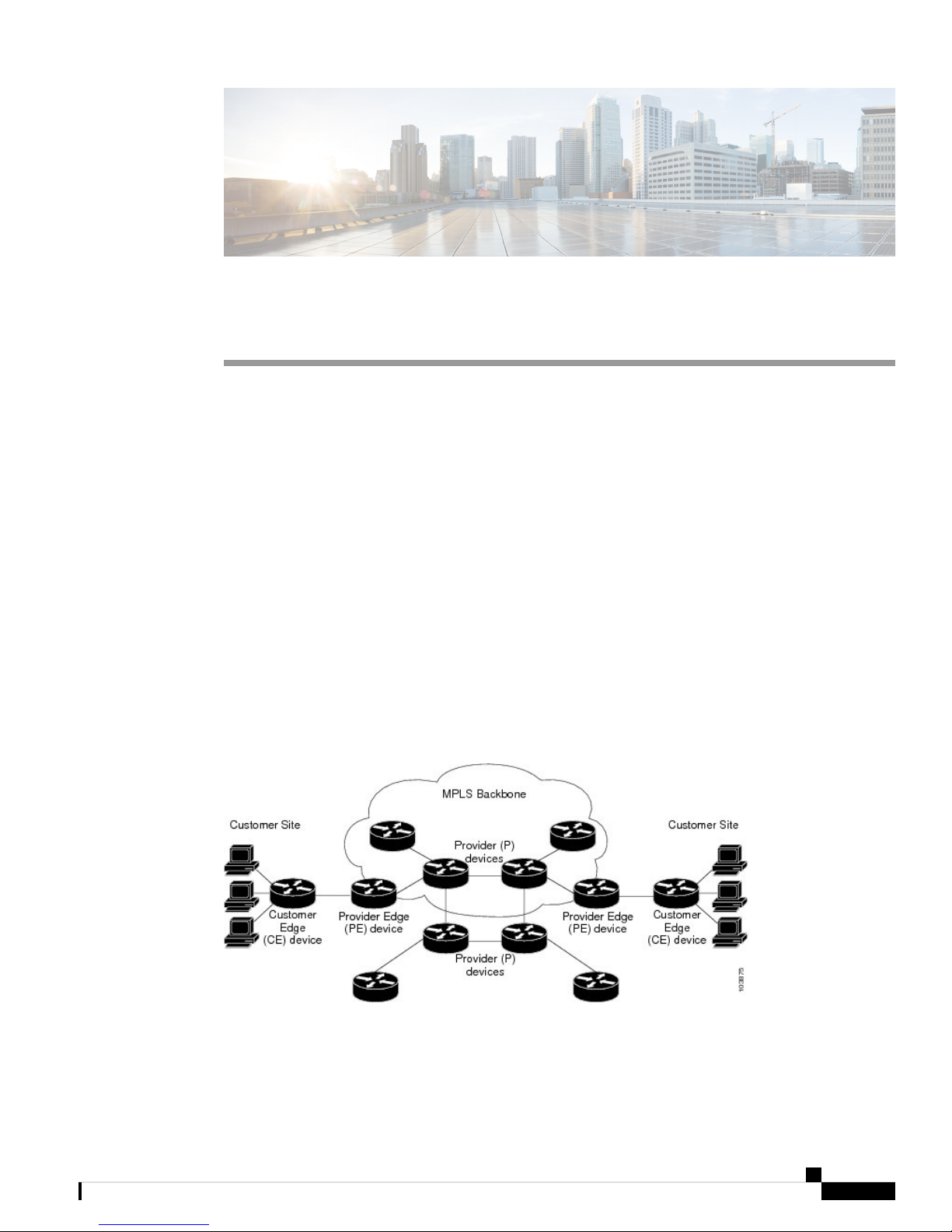
The following figure depicts a basic MPLS VPN topology.
Figure 1: Basic MPLS VPN Topology
These are the basic components of MPLS VPN:
L3VPN Configuration Guide for Cisco NCS 540 Series Routers, IOS XR Release 6.3.x
1
Page 12

How MPLS L3VPN Works
MPLS L3VPN Overview
• Provider (P) router—Router in the core of the provider network. P routers run MPLS switching and do
not attach VPN labels to routed packets. VPN labels are used to direct data packets to the correct private
network or customer edge router.
• PE router—Router that attaches the VPN label to incoming packets based on the interface or sub-interface
on which they are received, and also attaches the MPLS core labels. A PE router attaches directly to a
CE router.
• Customer (C) router—Router in the Internet service provider (ISP) or enterprise network.
• Customer edge (CE) router—Edge router on the network of the ISP that connects to the PE router on the
network. A CE router must interface with a PE router.
• How MPLS L3VPN Works, on page 2
• How to Implement MPLS Layer 3 VPNs, on page 8
• VRF-lite, on page 43
• MPLS L3VPN Services using Segment Routing, on page 47
• Implementing MPLS L3VPNs - References, on page 52
How MPLS L3VPN Works
MPLS VPN functionality is enabled at the edge of an MPLS network. The PE router performs the following
tasks:
• Exchanges routing updates with the CE router
• Translates the CE routing information into VPN version 4 (VPNv4) routes
• Exchanges VPNv4 routes with other PE routers through the Multiprotocol Border Gateway Protocol
(MP-BGP)
Major Components of MPLS L3VPN
An MPLS-based VPN network has three major components:
• VPN route target communities—A VPN route target community is a list of all members of a VPN
community. VPN route targets need to be configured for each VPN community member.
• Multiprotocol BGP (MP-BGP) peering of the VPN community PE routers—MP-BGP propagates VRF
reachability information to all members of a VPN community. MP-BGP peering needs to be configured
in all PE routers within a VPN community.
• MPLS forwarding—MPLS transports all traffic between all VPN community members across a VPN
service-provider network.
A one-to-one relationship does not necessarily exist between customer sites and VPNs. A given site can be a
member of multiple VPNs. However, a site can associate with only one VRF. A customer-site VRF contains
all the routes available to the site from the VPNs of which it is a member.
Read more at Major Components of MPLS L3VPN—Details, on page 52.
L3VPN Configuration Guide for Cisco NCS 540 Series Routers, IOS XR Release 6.3.x
2
Page 13

MPLS L3VPN Overview
Restrictions for MPLS L3VPN
Implementing MPLS L3VPN in Cisco NCS 540 Series Routers is subjected to these restrictions:
• The Cisco NCS 540 Series router supports only 16 ECMP paths.
• Fragmentation of MPLS packets that exceed egress MTU is not supported. Fragmentation is not supported
for IP->MPLS imposition as well. Hence, it is recommended to use Maximum MTU (9216) value on all
interfaces in the MPLS core.
• L3VPN prefix lookup always yields a single path. In case of multiple paths at IGP or BGP level, path
selection at each level is done using the prefix hash in control plane. The selected path is programmed
in the data plane.
• TTL propagation cannot be disabled. TTL propagation always happens from IP->MPLS and MPLS->IP.
Apart from the specific ones mentioned above, these generic restrictions for implementing MPLS L3VPNs
also apply for Cisco NCS 540 Series Routers:
• Multihop VPN-IPv4 eBGP is not supported for configuring eBGP routing between autonomous systems
or subautonomous systems in an MPLS VPN.
Restrictions for MPLS L3VPN
• MPLS VPN supports only IPv4 address families.
The following platform restrictions apply only to Cisco NCS 540 Series router:
• MPLS-TE stats is not supported.
• MPLS stats is not supported on show mpls forwarding command output and does not show any MPLS
stats.
The following restrictions apply when configuring MPLS VPN Inter-AS with ASBRs exchanging IPv4 routes
and MPLS labels:
• For networks configured with eBGP multihop, a label switched path (LSP) must be configured between
non adjacent routers.
Note
The physical interfaces that connect the BGP speakers must support FIB and MPLS.
Inter-AS Support for L3VPN
This section contains the following topics:
Inter-AS Support: Overview
An autonomous system (AS) is a single network or group of networks that is controlled by a common system
administration group and uses a single, clearly defined routing protocol.
As VPNs grow, their requirements expand. In some cases, VPNs need to reside on different autonomous
systems in different geographic areas. In addition, some VPNs need to extend across multiple service providers
(overlapping VPNs). Regardless of the complexity and location of the VPNs, the connection between
autonomous systems must be seamless.
L3VPN Configuration Guide for Cisco NCS 540 Series Routers, IOS XR Release 6.3.x
3
Page 14

Inter-AS and ASBRs
MPLS L3VPN Overview
An MPLS VPN Inter-AS provides the following benefits:
• Allows a VPN to cross more than one service provider backbone.
Service providers, running separate autonomous systems, can jointly offer MPLS VPN services to the
same end customer. A VPN can begin at one customer site and traverse different VPN service provider
backbones before arriving at another site of the same customer. Previously, MPLS VPN could traverse
only a single BGP autonomous system service provider backbone. This feature lets multiple autonomous
systems form a continuous, seamless network between customer sites of a service provider.
• Allows a VPN to exist in different areas.
A service provider can create a VPN in different geographic areas. Having all VPN traffic flow through
one point (between the areas) allows for better rate control of network traffic between the areas.
• Allows confederations to optimize iBGP meshing.
Internal Border Gateway Protocol (iBGP) meshing in an autonomous system is more organized and
manageable. You can divide an autonomous system into multiple, separate subautonomous systems and
then classify them into a single confederation. This capability lets a service provider offer MPLS VPNs
across the confederation, as it supports the exchange of labeled VPN-IPv4 Network Layer Reachability
Information (NLRI) between the subautonomous systems that form the confederation.
Inter-AS and ASBRs
Separate autonomous systems from different service providers can communicate by exchanging IPv4 NLRI
and IPv6 in the form of VPN-IPv4 addresses. The ASBRs use eBGP to exchange that information. Then an
Interior Gateway Protocol (IGP) distributes the network layer information for VPN-IPV4 prefixes throughout
each VPN and each autonomous system. The following protocols are used for sharing routing information:
• Within an autonomous system, routing information is shared using an IGP.
• Between autonomous systems, routing information is shared using an eBGP. An eBGP lets service
providers set up an interdomain routing system that guarantees the loop-free exchange of routing
information between separate autonomous systems.
The primary function of an eBGP is to exchange network reachability information between autonomous
systems, including information about the list of autonomous system routes. The autonomous systems
use EBGP border edge routers to distribute the routes, which include label switching information. Each
border edge router rewrites the next-hop and MPLS labels.
Inter-AS configurations supported in an MPLS VPN can include:
• Interprovider VPN—MPLS VPNs that include two or more autonomous systems, connected by
separate border edge routers. The autonomous systems exchange routes using eBGP. No IGP or
routing information is exchanged between the autonomous systems.
• BGP Confederations—MPLS VPNs that divide a single autonomous system into multiple
subautonomous systems and classify them as a single, designated confederation. The network
recognizes the confederation as a single autonomous system. The peers in the different autonomous
systems communicate over eBGP sessions; however, they can exchange route information as if they
were iBGP peers.
L3VPN Configuration Guide for Cisco NCS 540 Series Routers, IOS XR Release 6.3.x
4
Page 15

MPLS L3VPN Overview
Confederations
Confederations
A confederation is multiple subautonomous systems grouped together. A confederation reduces the total
number of peer devices in an autonomous system. A confederation divides an autonomous system into
subautonomous systems and assigns a confederation identifier to the autonomous systems. A VPN can span
service providers running in separate autonomous systems or multiple subautonomous systems that form a
confederation.
In a confederation, each subautonomous system is fully meshed with other subautonomous systems. The
subautonomous systems communicate using an IGP, such as Open Shortest Path First (OSPF) or Intermediate
System-to-Intermediate System (IS-IS). Each subautonomous system also has an eBGP connection to the
other subautonomous systems. The confederation eBGP (CEBGP) border edge routers forward next-hop-self
addresses between the specified subautonomous systems. The next-hop-self address forces the BGP to use a
specified address as the next hop rather than letting the protocol choose the next hop.
You can configure a confederation with separate subautonomous systems two ways:
• Configure a router to forward next-hop-self addresses between only the CEBGP border edge routers
(both directions). The subautonomous systems (iBGP peers) at the subautonomous system border do not
forward the next-hop-self address. Each subautonomous system runs as a single IGP domain. However,
the CEBGP border edge router addresses are known in the IGP domains.
• Configure a router to forward next-hop-self addresses between the CEBGP border edge routers (both
directions) and within the iBGP peers at the subautonomous system border. Each subautonomous system
runs as a single IGP domain but also forwards next-hop-self addresses between the PE routers in the
domain. The CEBGP border edge router addresses are known in the IGP domains.
Note
eBGP Connection Between Two Subautonomous Systems in a Confederation figure illustrates how two
autonomous systems exchange routes and forward packets. Subautonomous systems in a confederation use
a similar method of exchanging routes and forwarding packets.
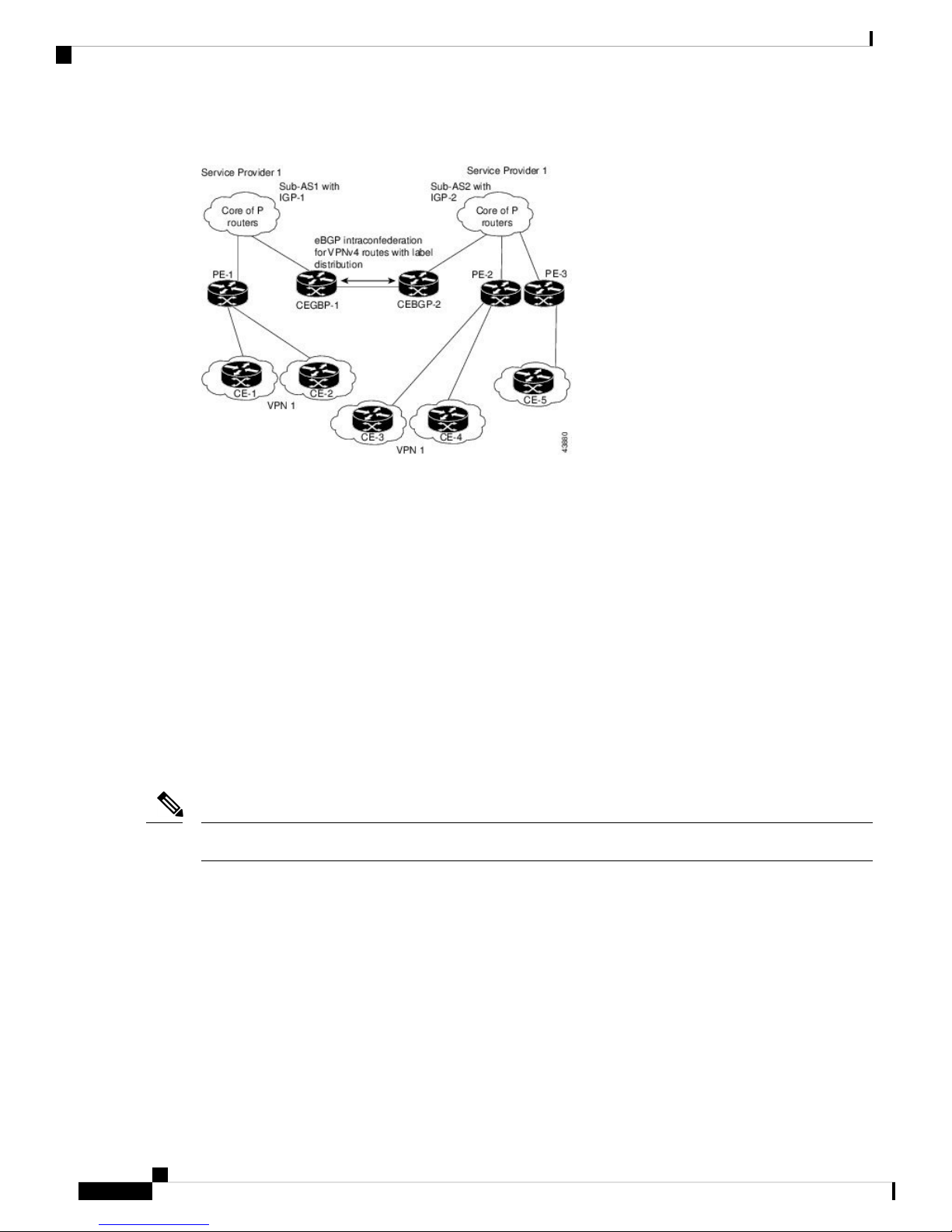
The figure below illustrates a typical MPLS VPN confederation configuration. In this configuration:
• The two CEBGP border edge routers exchange VPN-IPv4 addresses with labels between the two
autonomous systems.
• The distributing router changes the next-hop addresses and labels and uses a next-hop-self address.
• IGP-1 and IGP-2 know the addresses of CEBGP-1 and CEBGP-2.
L3VPN Configuration Guide for Cisco NCS 540 Series Routers, IOS XR Release 6.3.x
5
Page 16
MPLS VPN Inter-AS BGP Label Distribution
Figure 2: eBGP Connection Between Two Subautonomous Systems in a Confederation
In this confederation configuration:
MPLS L3VPN Overview
• CEBGP border edge routers function as neighboring peers between the subautonomous systems. The
subautonomous systems use eBGP to exchange route information.
• Each CEBGP border edge router (CEBGP-1 and CEBGP-2) assigns a label for the router before distributing
the route to the next subautonomous system. The CEBGP border edge router distributes the route as a
VPN-IPv4 address by using the multiprotocol extensions of BGP. The label and the VPN identifier are
encoded as part of the NLRI.
• Each PE and CEBGP border edge router assigns its own label to each VPN-IPv4 address prefix before
redistributing the routes. The CEBGP border edge routers exchange IPV-IPv4 addresses with the labels.
The next-hop-self address is included in the label (as the value of the eBGP next-hop attribute). Within
the subautonomous systems, the CEBGP border edge router address is distributed throughout the iBGP
neighbors, and the two CEBGP border edge routers are known to both confederations.
MPLS VPN Inter-AS BGP Label Distribution
Note
This section is not applicable to Inter-AS over IP tunnels.
You can set up the MPLS VPN Inter-AS network so that the ASBRs exchange IPv4 routes with MPLS labels
of the provider edge (PE) routers. Route reflectors (RRs) exchange VPN-IPv4 routes by using multihop,
multiprotocol external Border Gateway Protocol (eBGP). This method of configuring the Inter-AS system is
often called MPLS VPN Inter-AS BGP Label Distribution.
Configuring the Inter-AS system so that the ASBRs exchange the IPv4 routes and MPLS labels has the
following benefits:
• Saves the ASBRs from having to store all the VPN-IPv4 routes. Using the route reflectors to store the
VPN-IPv4 routes and forward them to the PE routers results in improved scalability compared with
configurations in which the ASBR holds all the VPN-IPv4 routes and forwards the routes based on
VPN-IPv4 labels.
L3VPN Configuration Guide for Cisco NCS 540 Series Routers, IOS XR Release 6.3.x
6
Page 17
MPLS L3VPN Overview
• Having the route reflectors hold the VPN-IPv4 routes also simplifies the configuration at the border of
the network.
• Enables a non-VPN core network to act as a transit network for VPN traffic. You can transport IPv4
routes with MPLS labels over a non-MPLS VPN service provider.
• Eliminates the need for any other label distribution protocol between adjacent label switch routers (LSRs).
If two adjacent LSRs are also BGP peers, BGP can handle the distribution of the MPLS labels. No other
label distribution protocol is needed between the two LSRs.
Exchanging IPv4 Routes with MPLS labels
Note
This section is not applicable to Inter-AS over IP tunnels.
You can set up a VPN service provider network to exchange IPv4 routes with MPLS labels. You can configure
the VPN service provider network as follows:
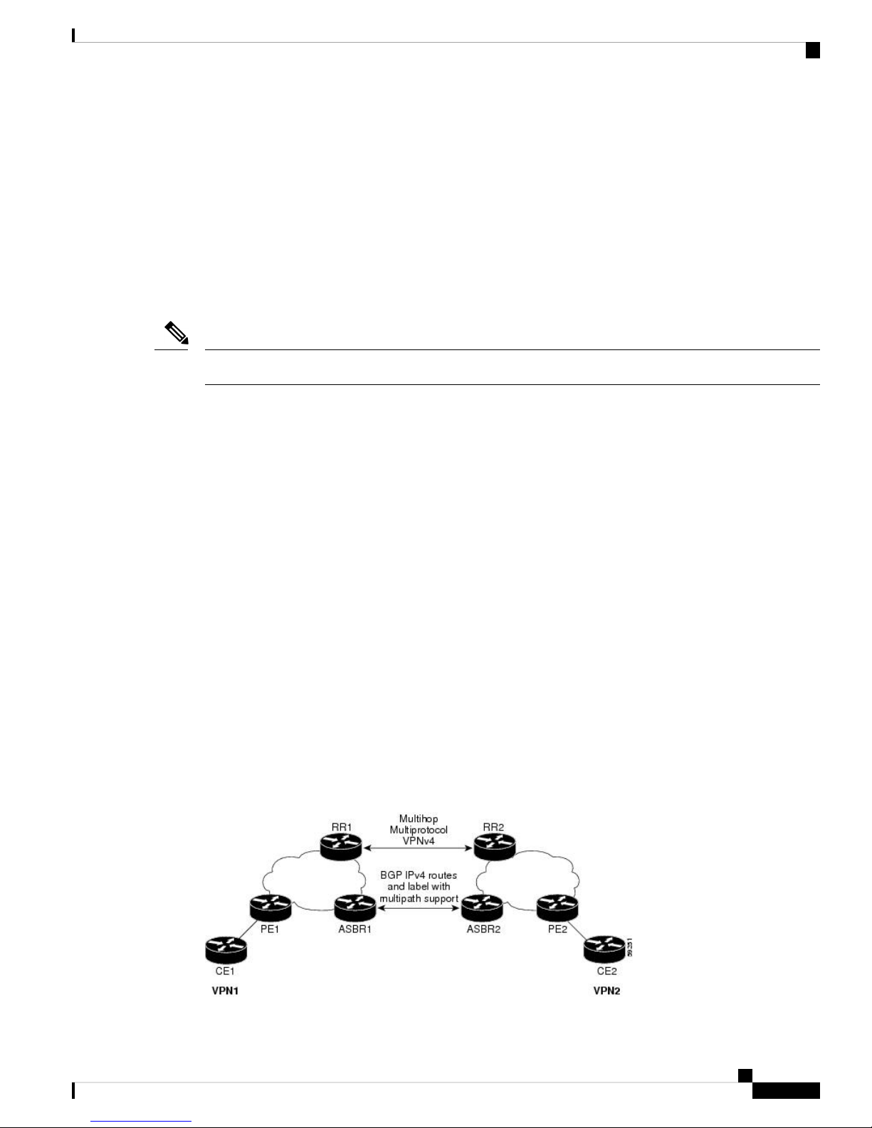
• Route reflectors exchange VPN-IPv4 routes by using multihop, multiprotocol eBGP. This configuration
also preserves the next-hop information and the VPN labels across the autonomous systems.
Exchanging IPv4 Routes with MPLS labels
• A local PE router (for example, PE1 in the figure below) needs to know the routes and label information
for the remote PE router (PE2).
This information can be exchanged between the PE routers and ASBRs in one of two ways:
• Internal Gateway Protocol (IGP) and Label Distribution Protocol (LDP): The ASBR can redistribute
the IPv4 routes and MPLS labels it learned from eBGP into IGP and LDP and from IGP and LDP
into eBGP.
• Internal Border Gateway Protocol (iBGP) IPv4 label distribution: The ASBR and PE router can use
direct iBGP sessions to exchange VPN-IPv4 and IPv4 routes and MPLS labels.
Alternatively, the route reflector can reflect the IPv4 routes and MPLS labels learned from the ASBR to the
PE routers in the VPN. This reflecting of learned IPv4 routes and MPLS labels is accomplished by enabling
the ASBR to exchange IPv4 routes and MPLS labels with the route reflector. The route reflector also reflects
the VPN-IPv4 routes to the PE routers in the VPN. For example, in VPN1, RR1 reflects to PE1 the VPN-IPv4
routes it learned and IPv4 routes and MPLS labels learned from ASBR1. Using the route reflectors to store
the VPN-IPv4 routes and forward them through the PE routers and ASBRs allows for a scalable configuration.
Figure 3: VPNs Using eBGP and iBGP to Distribute Routes and MPLS Labels
L3VPN Configuration Guide for Cisco NCS 540 Series Routers, IOS XR Release 6.3.x
7
Page 18

BGP Routing Information
BGP Routing Information
BGP routing information includes the following items:
• Network number (prefix), which is the IP address of the destination.
• Autonomous system (AS) path, which is a list of the other ASs through which a route passes on the way
to the local router. The first AS in the list is closest to the local router; the last AS in the list is farthest
from the local router and usually the AS where the route began.
• Path attributes, which provide other information about the AS path, for example, the next hop.
BGP Messages and MPLS Labels
MPLS labels are included in the update messages that a router sends. Routers exchange the following types
of BGP messages:
• Open messages—After a router establishes a TCP connection with a neighboring router, the routers
exchange open messages. This message contains the number of the autonomous system to which the
router belongs and the IP address of the router that sent the message.
• Update messages—When a router has a new, changed, or broken route, it sends an update message to
the neighboring router. This message contains the NLRI, which lists the IP addresses of the usable routes.
The update message includes any routes that are no longer usable. The update message also includes
path attributes and the lengths of both the usable and unusable paths. Labels for VPN-IPv4 routes are
encoded in the update message, as specified in RFC 2858. The labels for the IPv4 routes are encoded in
the update message, as specified in RFC 3107.
MPLS L3VPN Overview
• Keepalive messages—Routers exchange keepalive messages to determine if a neighboring router is still
available to exchange routing information. The router sends these messages at regular intervals. (Sixty
seconds is the default for Cisco routers.) The keepalive message does not contain routing data; it contains
only a message header.
• Notification messages—When a router detects an error, it sends a notification message.
Sending MPLS Labels with Routes
When BGP (eBGP and iBGP) distributes a route, it can also distribute an MPLS label that is mapped to that
route. The MPLS label mapping information for the route is carried in the BGP update message that contains
the information about the route. If the next hop is not changed, the label is preserved.
When you issue the show bgp neighbors ip-address command on both BGP routers, the routers advertise to
each other that they can then send MPLS labels with the routes. If the routers successfully negotiate their
ability to send MPLS labels, the routers add MPLS labels to all outgoing BGP updates.
How to Implement MPLS Layer 3 VPNs
Implementing MPLS L3VPNs involves these main tasks:
• Configure the Core Network, on page 9
• Connect MPLS VPN Customers, on page 15
L3VPN Configuration Guide for Cisco NCS 540 Series Routers, IOS XR Release 6.3.x
8
Page 19
MPLS L3VPN Overview
Prerequisites for Implementing MPLS L3VPN
These are the prerequisites to configure MPLS L3VPN:
• You must be in a user group associated with a task group that includes the proper task IDs for these
commands:
• • BGP
• IGP
• MPLS
• MPLS Layer 3 VPN
• If you suspect user group assignment is preventing you from using a command, contact your AAA
administrator for assistance.
• To configure MPLS Layer 3 VPNs, routers must support MPLS forwarding and Forwarding Information
Base (FIB).
Prerequisites for Implementing MPLS L3VPN
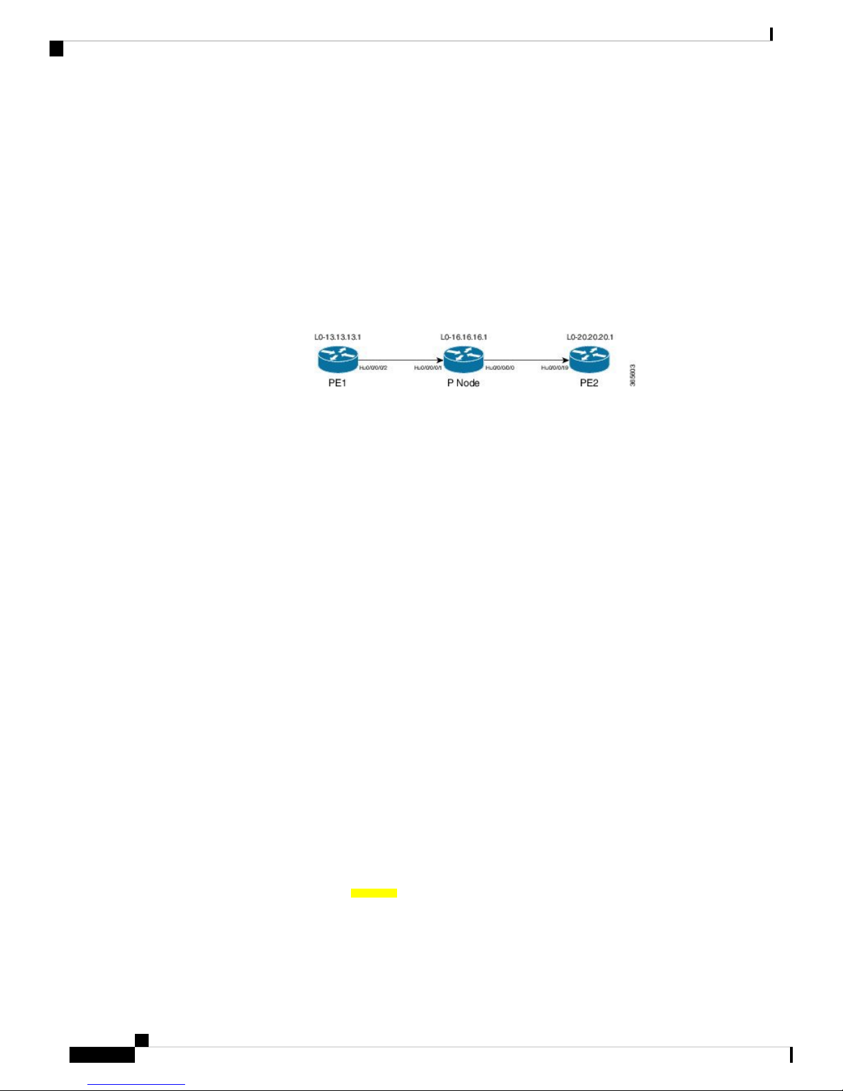
Configure the Core Network
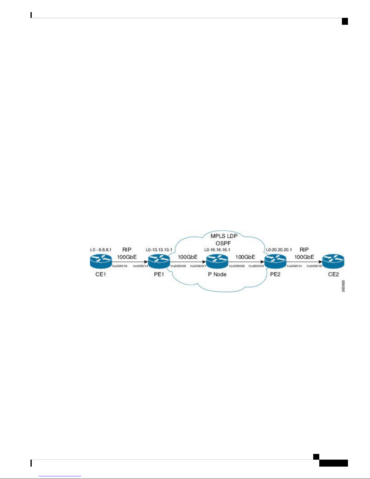
Consider a network topology where MPLS L3VPN services are transported over MPLS LDP core.
Figure 4: L3VPN over MPLS LDP
Configuring the core network involves these main tasks:
• Assess the Needs of MPLS VPN Customers, on page 9
• Configure Routing Protocols in the Core, on page 10
• Configure MPLS in the Core, on page 11
• Determine if FIB is Enabled in the Core, on page 12
• Configure Multiprotocol BGP on the PE Routers and Route Reflectors, on page 12
Assess the Needs of MPLS VPN Customers
Before configuring an MPLS VPN, the core network topology must be identified so that it can best serve
MPLS VPN customers. The tasks listed below helps to identify the core network topology.
• Identify the size of the network:
Identify the following to determine the number of routers and ports required:
L3VPN Configuration Guide for Cisco NCS 540 Series Routers, IOS XR Release 6.3.x
9
Page 20
Configure Routing Protocols in the Core
• How many customers to be supported?
• How many VPNs are required for each customer?
• How many virtual routing and forwarding (VRF) instances are there for each VPN?
• Determine the routing protocols required in the core.
• Determine if BGP load sharing and redundant paths in the MPLS VPN core are required.
Configure Routing Protocols in the Core
You can use RIP, OSPF or IS-IS as the routing protocol in the core.
Figure 5: OSPF as Routing Protocol in the Core
Configuration Example
MPLS L3VPN Overview
This example lists the steps to configure OSPF as the routing protocol in the core.
Router-PE1#configure
Router-PE1(config)#router ospf dc-core
Router-PE1(config-ospf)#address-family ipv4 unicast
Router-PE1(config-ospf)#area 1
Router-PE1(config-ospf-ar)#interface HundredGigE0/0/1/0
Router-PE1(config-ospf-vrf-ar-if)#commit
Running Configuration
router ospf dc-core
router-id 13.13.13.1
address-family ipv4 unicast
area 1
interface HundredGigE0/0/1/0
!
!
!
Verification
• Verify the OSPF neighbor and ensure that the State is displayed as 'FULL'.
Router-PE1# show ospf neighbor
Neighbors for OSPF dc-core
Neighbor ID Pri State Dead Time Address Interface
16.16.16.1 1 FULL/DR 00:00:34 191.22.1.2 HundredGigE0/0/1/0
Neighbor is up for 1d18h
Total neighbor count: 1
L3VPN Configuration Guide for Cisco NCS 540 Series Routers, IOS XR Release 6.3.x
10
Page 21

MPLS L3VPN Overview
Related Topics
• How to Implement MPLS Layer 3 VPNs, on page 8
For more details on configuring the routing protocol, see Routing Configuration Guide for Cisco NCS 540
Series Routers and BGP Configuration Guide for Cisco NCS 540 Series Routers.
Configure MPLS in the Core
To enable MPLS on all routers in the core, you must configure a Label Distribution Protocol (LDP).
You can also transport MPLS L3VPN services using segment routing in the core. For details, see Configure
Segment Routing in MPLS Core, on page 48.
Configuration Example
This example lists the steps to configure LDP in MPLS core.
Router-PE1#configure
Router-PE1(config)#mpls ldp
Router-PE1(config-ldp)#router-id 13.13.13.1
Router-PE1(config-ldp)#address-family ipv4
Router-PE1(config-ldp-af)#exit
Router-PE1(config-ldp)#interface HundredGigE0/0/1/0
Router-PE1(config-ldp)#commit
Configure MPLS in the Core
Repeat this configuration in PE2 and P routers as well.
Running Configuration
mpls ldp
router-id 13.13.13.1
address-family ipv4
!
interface HundredGigE0/0/1/0
!
!
Verification
• Verify that the neighbor (16.16.16.1) is UP through the core interface:
Router-PE1#show mpls ldp neighbor
Peer LDP Identifier: 16.16.16.1:0
TCP connection: 16.16.16.1:47619 - 13.13.13.1:646
Graceful Restart: No
Session Holdtime: 180 sec
State: Oper; Msgs sent/rcvd: 40395/35976; Downstream-Unsolicited
Up time: 2w2d
LDP Discovery Sources:
IPv4: (1)
HundredGigE0/0/1/0
IPv6: (0)
Addresses bound to this peer:
IPv4: (6)
10.64.98.32 87.0.0.2 88.88.88.14 50.50.50.50
L3VPN Configuration Guide for Cisco NCS 540 Series Routers, IOS XR Release 6.3.x
11
Page 22

Determine if FIB is Enabled in the Core
178.0.0.1 192.1.1.1
IPv6: (0)
Related Topics
• How to Implement MPLS Layer 3 VPNs, on page 8
For more details on configuring MPLS LDP, see the Implementing MPLS Label Distribution Protocol chapter
in the MPLS Configuration Guide for Cisco NCS 540 Series Routers.
Determine if FIB is Enabled in the Core
Forwarding Information Base (FIB) must be enabled on all routers in the core, including the provider edge
(PE) routers. For information on how to determine if FIB is enabled, see the Implementing Cisco Express
Forwarding module in the IP Addresses and Services Configuration Guide for Cisco NCS 540 Series Routers.
Configure Multiprotocol BGP on the PE Routers and Route Reflectors
Multiprotocol BGP (MP-BGP) propagates VRF reachability information to all members of a VPN community.
You must configure MP-BGP peering in all the PE routers within a VPN community.
Figure 6: Multiprotocol BGP on PE Routers
MPLS L3VPN Overview
Configuration Example
This example shows how to configure MP-BGP on PE1. The loopback address (20.20.20.1) of PE2 is specified
as the neighbor of PE1. Similarly, you must perform this configuration on PE2 node as well, with the loopback
address (13.13.13.1) of PE1 specified as the neighbor of PE2.
Router-PE1#configure
Router-PE1(config)#router bgp 2001
Router-PE1(config-bgp)#bgp router-id 13.13.13.1
Router-PE1(config-bgp)#address-family ipv4 unicast
Router-PE1(config-bgp-af)#exit
Router-PE1(config-bgp)#address-family vpnv4 unicast
Router-PE1(config-bgp-af)#exit
Router-PE1(config-bgp)#neighbor 20.20.20.1
Router-PE1(config-bgp-nbr)#remote-as 2001
Router-PE1(config-bgp-nbr)#update-source loopback 0
Router-PE1(config-bgp-nbr)#address-family ipv4 unicast
Router-PE1(config-bgp-nbr-af)#exit
Router-PE1(config-bgp-nbr)#address-family vpnv4 unicast
Router-PE1(config-bgp-nbr-af)#exit
Router-PE1(config-bgp-nbr)#exit
/* VRF configuration */
Router(config-bgp)# vrf vrf1601
Router-PE1(config-bgp-vrf)#rd 2001:1601
Router-PE1(config-bgp-vrf)#address-family ipv4 unicast
Router-PE1(config-bgp-vrf-af)#label mode per-vrf
L3VPN Configuration Guide for Cisco NCS 540 Series Routers, IOS XR Release 6.3.x
12
Page 23

MPLS L3VPN Overview
Configure Multiprotocol BGP on the PE Routers and Route Reflectors
Router-PE1(config-bgp-vrf-af)#redistribute connected
Router-PE1(config-bgp-vrf-af)#commit
Running Configuration
router bgp 2001
bgp router-id 13.13.13.1
address-family ipv4 unicast
!
address-family vpnv4 unicast
!
neighbor 20.20.20.1
remote-as 2001
update-source Loopback0
address-family vpnv4 unicast
!
address-family ipv4 unicast
!
!
vrf vrf1601
rd 2001:1601
address-family ipv4 unicast
label mode per-vrf
redistribute connected
!
!
Verification
• Verify if the BGP state is established, and if the Remote AS and local AS displays the same value (2001
in this example):
Router-PE1#show bgp neighbor
BGP neighbor is 20.20.20.1
Remote AS 2001, local AS 2001, internal link
Remote router ID 20.20.20.1
BGP state = Established, up for 1d19h
NSR State: None
Last read 00:00:04, Last read before reset 00:00:00
Hold time is 60, keepalive interval is 20 seconds
Configured hold time: 60, keepalive: 30, min acceptable hold time: 3
Last write 00:00:16, attempted 19, written 19
Second last write 00:00:36, attempted 19, written 19
Last write before reset 00:00:00, attempted 0, written 0
Second last write before reset 00:00:00, attempted 0, written 0
Last write pulse rcvd Apr 12 10:31:20.739 last full not set pulse count 27939
Last write pulse rcvd before reset 00:00:00
Socket not armed for io, armed for read, armed for write
Last write thread event before reset 00:00:00, second last 00:00:00
Last KA expiry before reset 00:00:00, second last 00:00:00
Last KA error before reset 00:00:00, KA not sent 00:00:00
Last KA start before reset 00:00:00, second last 00:00:00
Precedence: internet
Non-stop routing is enabled
Multi-protocol capability received
Neighbor capabilities:
Route refresh: advertised (old + new) and received (old + new)
Graceful Restart (GR Awareness): received
L3VPN Configuration Guide for Cisco NCS 540 Series Routers, IOS XR Release 6.3.x
13
Page 24

Configure Multiprotocol BGP on the PE Routers and Route Reflectors
4-byte AS: advertised and received
Address family IPv4 Unicast: advertised and received
Address family VPNv4 Unicast: advertised and received
Received 25595 messages, 0 notifications, 0 in queue
Sent 8247 messages, 0 notifications, 0 in queue
Minimum time between advertisement runs is 0 secs
Inbound message logging enabled, 3 messages buffered
Outbound message logging enabled, 3 messages buffered
For Address Family: IPv4 Unicast
BGP neighbor version 484413
Update group: 0.4 Filter-group: 0.3 No Refresh request being processed
Inbound soft reconfiguration allowed
NEXT_HOP is always this router
AF-dependent capabilities:
Outbound Route Filter (ORF) type (128) Prefix:
Send-mode: advertised, received
Receive-mode: advertised, received
Graceful Restart capability received
Remote Restart time is 120 seconds
Neighbor did not preserve the forwarding state during latest restart
Additional-paths Send: advertised and received
Additional-paths Receive: advertised and received
Route refresh request: received 1, sent 1
Policy for incoming advertisements is pass-all
Policy for outgoing advertisements is pass-all
24260 accepted prefixes, 24260 are bestpaths
Cumulative no. of prefixes denied: 0.
Prefix advertised 2000, suppressed 0, withdrawn 0
Maximum prefixes allowed 1048576
Threshold for warning message 75%, restart interval 0 min
AIGP is enabled
An EoR was received during read-only mode
Last ack version 484413, Last synced ack version 0
Outstanding version objects: current 0, max 1
Additional-paths operation: Send and Receive
Send Multicast Attributes
Advertise VPNv4 routes enabled with defaultReoriginate,disable Local with stitching-RT
option
MPLS L3VPN Overview
For Address Family: VPNv4 Unicast
BGP neighbor version 798487
Update group: 0.2 Filter-group: 0.1 No Refresh request being processed
AF-dependent capabilities:
Graceful Restart capability received
Remote Restart time is 120 seconds
Neighbor did not preserve the forwarding state during latest restart
Additional-paths Send: advertised and received
Additional-paths Receive: advertised and received
Route refresh request: received 0, sent 0
29150 accepted prefixes, 29150 are bestpaths
Cumulative no. of prefixes denied: 0.
Prefix advertised 7200, suppressed 0, withdrawn 0
Maximum prefixes allowed 2097152
Threshold for warning message 75%, restart interval 0 min
AIGP is enabled
An EoR was received during read-only mode
Last ack version 798487, Last synced ack version 0
Outstanding version objects: current 0, max 1
Additional-paths operation: Send and Receive
Send Multicast Attributes
Advertise VPNv4 routes enabled with defaultReoriginate,disable Local with stitching-RT
option
L3VPN Configuration Guide for Cisco NCS 540 Series Routers, IOS XR Release 6.3.x
14
Page 25

MPLS L3VPN Overview
Connect MPLS VPN Customers
Connections established 1; dropped 0
Local host: 13.13.13.1, Local port: 35018, IF Handle: 0x00000000
Foreign host: 20.20.20.1, Foreign port: 179
Last reset 00:00:00
• Verify if all the IP addresses are learnt on PE1 from PE2:
Router-PE1#show bgp vpnv4 unicast
BGP router identifier 13.13.13.1, local AS number 2001
BGP generic scan interval 60 secs
Non-stop routing is enabled
BGP table state: Active
Table ID: 0x0 RD version: 0
BGP main routing table version 798487
BGP NSR Initial initsync version 15151 (Reached)
BGP NSR/ISSU Sync-Group versions 0/0
BGP scan interval 60 secs
Status codes: s suppressed, d damped, h history, * valid, > best
Origin codes: i - IGP, e - EGP, ? - incomplete
Network Next Hop Metric LocPrf Weight Path
Route Distinguisher: 2001:1601 (default for vrf vrf1601)
*> 20.13.1.1/32 192.13.26.5 0 7501 i
*> 20.13.1.2/32 192.13.26.5 0 7501 i
*> 20.13.1.3/32 192.13.26.5 0 7501 i
*> 20.13.1.4/32 192.13.26.5 0 7501 i
*> 20.13.1.5/32 192.13.26.5 0 7501 i
*>i20.14.1.1/3214.14.14.1 100 0 8501 i
*>i20.14.1.2/3214.14.14.1 100 0 8501 i
*>i20.14.1.3/3214.14.14.1 100 0 8501 i
*>i20.14.1.4/3214.14.14.1 100 0 8501 i
*>i20.14.1.5/3214.14.14.1 100 0 8501 i
i - internal, r RIB-failure, S stale, N Nexthop-discard
Related Topics
• Configure the Core Network, on page 9
• Define VRFs on PE Routers to Enable Customer Connectivity, on page 16
For more details on Multiprotocol BGP, see BGP Configuration Guide for Cisco NCS 540 Series Routers.
Associated Commands
Connect MPLS VPN Customers
Connecting MPLS VPN customers involves these main tasks:
• Define VRFs on PE Routers to Enable Customer Connectivity, on page 16
• Configure VRF Interfaces on PE Routers for Each VPN Customer, on page 17
• Configure the Routing Protocol between the PE and CE Routers
Use any of these options:
L3VPN Configuration Guide for Cisco NCS 540 Series Routers, IOS XR Release 6.3.x
15
Page 26

Define VRFs on PE Routers to Enable Customer Connectivity
• Configure BGP as the Routing Protocol Between the PE and CE Routers, on page 18
• Configure RIPv2 as the Routing Protocol Between the PE and CE Routers, on page 22
• Configure Static Routes Between the PE and CE Routers, on page 23
• Configure OSPF as the Routing Protocol Between the PE and CE Routers, on page 24
Define VRFs on PE Routers to Enable Customer Connectivity
VPN routing and forwarding (VRF) defines the VPN membership of a customer site attached to a PE router.
A one-to-one relationship does not necessarily exist between customer sites and VPNs. A site can be a member
of multiple VPNs. However, a site can associate with only one VRF. A VRF contains all the routes available
to the site from the VPNs of which it is a member. The distribution of VPN routing information is controlled
through the use of VPN route target communities, implemented by BGP extended communities.
Configuration Example
This example configures a VRF instance (vrf1601) and specifies the import and export route-targets(2001:1601).
The import route policy is the one that can be imported into the local VPN. The export route policy is the one
that can be exported from the local VPN. The import route-target configuration allows exported VPN routes
to be imported into the VPN if one of the route targets of the exported route matches one of the local VPN
import route targets. When the route is advertised to other PE routers, the export route target is sent along
with the route as an extended community.
MPLS L3VPN Overview
Router-PE1#configure
Router-PE1(config)#vrf vrf1601
Router-PE1(config-vrf)#address-family ipv4 unicast
Router-PE1(config-vrf-af)#import route-target
Router-PE1(config-vrf-af-import-rt)#2001:1601
Router-PE1(config-vrf-af-import-rt)#exit
Router-PE1(config-vrf-af)#export route-target
Router-PE1(config-vrf-af-export-rt)#2001:1601
Router-PE1(config-vrf-af-export-rt)#commit
This VRF instance is then associated with the respective BGP instance.
Running Configuration
vrf vrf1601
address-family ipv4 unicast
import route-target
2001:1601
!
export route-target
2001:1601
!
!
!
Verification
Verify the import and export route targets.
L3VPN Configuration Guide for Cisco NCS 540 Series Routers, IOS XR Release 6.3.x
16
Page 27

MPLS L3VPN Overview
Configure VRF Interfaces on PE Routers for Each VPN Customer
Router-PE1#show vrf vrf1601
VRF RD RT AFI SAFI
vrf1601 2001:1601
import 2001:1601 IPV4 Unicast
export 2001:1601 IPV4 Unicast
Related Topics
• Configure VRF Interfaces on PE Routers for Each VPN Customer, on page 17
• Configure Multiprotocol BGP on the PE Routers and Route Reflectors, on page 12
Configure VRF Interfaces on PE Routers for Each VPN Customer
After a VRF instance is created, you must associate that VRF instance with an interface or a sub-interface on
the PE routers.
Note
You must remove the IPv4 or IPv6 addresses from an interface prior to assigning, removing, or changing an
interface's VRF. If this is not done in advance, any attempt to change the VRF on an IP interface is rejected.
Configuration Example
This example assigns an IP address 192.13.26.6 to the interface (HundredGigE0/0/1/0.1601) on PE1 router
and associates the VRF instance vrf1601, to that interface.
Router-PE1#configure
Router-PE1(config)#interface HundredGigE0/0/1/0.1601
Router-PE1(config-if)#vrf vrf1601
Router-PE1(config-if)#ipv4 address 192.13.26.6 255.255.255.252
Router-PE1(config-if)#encapsulation dot1q 1601
Router-PE1(config)#commit
Running Configuration
interface HundredGigE0/0/1/0.1601
vrf vrf1601
ipv4 address 192.13.26.6 255.255.255.252
encapsulation dot1q 1601
!
Verification
• Verify that the interface with which the VRF is associated, is UP.
Router-PE1#show ipv4 vrf vrf1601 interface
HundredGigE0/0/1/0.1601 is Up, ipv4 protocol is Up
Vrf is vrf1601 (vrfid 0x60000001)
Internet address is 192.13.26.6/30
MTU is 1518 (1500 is available to IP)
Helper address is not set
L3VPN Configuration Guide for Cisco NCS 540 Series Routers, IOS XR Release 6.3.x
17
Page 28

Configure Routing Protocol Between the PE and CE Routers
Multicast reserved groups joined: 224.0.0.2 224.0.0.1
Directed broadcast forwarding is disabled
Outgoing access list is not set
Inbound common access list is not set, access list is not set
Proxy ARP is disabled
ICMP redirects are never sent
ICMP unreachables are always sent
ICMP mask replies are never sent
Table Id is 0xe0000001
Related Topics
• Define VRFs on PE Routers to Enable Customer Connectivity, on page 16
Configure Routing Protocol Between the PE and CE Routers
Configure BGP as the Routing Protocol Between the PE and CE Routers
BGP distributes reachability information for VPN-IPv4 prefixes for each VPN. PE to PE or PE to route
reflector (RR) sessions are iBGP sessions, and PE to CE sessions are eBGP sessions. PE to CE eBGP sessions
can be directly or indirectly connected (eBGP multihop).
Figure 7: BGP as the Routing Protocol between PE and CE Routers
MPLS L3VPN Overview
Configuration Example
This example lists the steps to configure BGP as the routing protocol between the PE and CE routers. The
route policy, pass-all in this example, must be configured before it can be attached.
PE1:
Router-PE1#configure
Router-PE1(config)#router bgp 2001
Router-PE1(config-bgp)#bgp router-id 13.13.13.1
Router-PE1(config-bgp)#address-family ipv4 unicast
Router-PE1(config-bgp-af)#exit
Router-PE1(config-bgp)#address-family vpnv4 unicast
Router-PE1(config-bgp-af)#exit
/* VRF configuration */
Router-PE1(config-bgp)#vrf vrf1601
Router-PE1(config-bgp-vrf)#rd 2001:1601
Router-PE1(config-bgp-vrf)#address-family ipv4 unicast
Router-PE1(config-bgp-vrf-af)#label mode per-vrf
Router-PE1(config-bgp-vrf-af)#redistribute connected
Router-PE1(config-bgp-vrf-af)#exit
Router-PE1(config-bgp-vrf)#neighbor 192.13.26.5
Router-PE1(config-bgp-vrf-nbr)#remote-as 7501
Router-PE1(config-bgp-vrf-nbr)#address-family ipv4 unicast
Router-PE1(config-bgp-vrf-nbr-af)#route-policy pass-all in
Router-PE1(config-bgp-vrf-nbr-af)#route-policy pass-all out
Router-PE1(config-bgp-vrf-nbr-af)#commit
L3VPN Configuration Guide for Cisco NCS 540 Series Routers, IOS XR Release 6.3.x
18
Page 29

MPLS L3VPN Overview
Configure BGP as the Routing Protocol Between the PE and CE Routers
CE1:
Router-CE1#configure
Router-CE1(config)#router bgp 2001
Router-CE1(config-bgp)#bgp router-id 8.8.8.1
Router-CE1(config-bgp)#address-family ipv4 unicast
Router-CE1(config-bgp-af)#exit
Router-CE1(config-bgp)#address-family vpnv4 unicast
Router-CE1(config-bgp-af)#exit
Router-CE1(config-bgp)#neighbor 192.13.26.6
Router-CE1(config-bgp-nbr)#remote-as 2001
Router-CE1(config-bgp-nbr)#address-family ipv4 unicast
Router-CE1(config-bgp-nbr-af)#route-policy pass-all in
Router-CE1(config-bgp-nbr-af)#route-policy pass-all out
Router-CE1(config-bgp-nbr-af)#commit
Running Configuration
PE1:
router bgp 2001
bgp router-id 13.13.13.1
address-family ipv4 unicast
!
address-family vpnv4 unicast
!
vrf vrf1601
rd 2001:1601
address-family ipv4 unicast
label mode per-vrf
redistribute connected
!
neighbor 192.13.26.5
remote-as 7501
address-family ipv4 unicast
route-policy pass-all in
route-policy pass-all out
!
!
!
CE1:
router bgp 7501
bgp router-id 8.8.8.1
address-family ipv4 unicast
!
address-family vpnv4 unicast
!
neighbor 192.13.26.6
remote-as 2001
address-family ipv4 unicast
route-policy pass-all in
route-policy pass-all out
!
!
L3VPN Configuration Guide for Cisco NCS 540 Series Routers, IOS XR Release 6.3.x
19
Page 30

Configure BGP as the Routing Protocol Between the PE and CE Routers
Verification
• PE1:
Router-PE1#show bgp neighbor
BGP neighbor is 192.13.26.5
Remote AS 6553700, local AS 2001, external link
Administratively shut down
Remote router ID 192.13.26.5
BGP state = Established
NSR State: None
Last read 00:00:04, Last read before reset 00:00:00
Hold time is 60, keepalive interval is 20 seconds
Configured hold time: 60, keepalive: 30, min acceptable hold time: 3
Last write 00:00:16, attempted 19, written 19
Second last write 00:00:36, attempted 19, written 19
Last write before reset 00:00:00, attempted 0, written 0
Second last write before reset 00:00:00, attempted 0, written 0
Last write pulse rcvd Apr 12 10:31:20.739 last full not set pulse count 27939
Last write pulse rcvd before reset 00:00:00
Socket not armed for io, armed for read, armed for write
Last write thread event before reset 00:00:00, second last 00:00:00
Last KA expiry before reset 00:00:00, second last 00:00:00
Last KA error before reset 00:00:00, KA not sent 00:00:00
Last KA start before reset 00:00:00, second last 00:00:00
Precedence: internet
Non-stop routing is enabled
Graceful restart is enabled
Restart time is 120 seconds
Stale path timeout time is 360 seconds
Enforcing first AS is enabled
Multi-protocol capability not received
Received 0 messages, 0 notifications, 0 in queue
Sent 0 messages, 0 notifications, 0 in queue
Minimum time between advertisement runs is 30 secs
Inbound message logging enabled, 3 messages buffered
Outbound message logging enabled, 3 messages buffered
MPLS L3VPN Overview
For Address Family: IPv4 Unicast
BGP neighbor version 0
Update group: 0.2 Filter-group: 0.0 No Refresh request being processed
Inbound soft reconfiguration allowed
AF-dependent capabilities:
Outbound Route Filter (ORF) type (128) Prefix:
Send-mode: advertised
Receive-mode: advertised
Graceful Restart capability advertised
Local restart time is 120, RIB purge time is 600 seconds
Maximum stalepath time is 360 seconds
Route refresh request: received 0, sent 0
Policy for incoming advertisements is pass-all
Policy for outgoing advertisements is pass-all
0 accepted prefixes, 0 are bestpaths
Cumulative no. of prefixes denied: 0.
Prefix advertised 0, suppressed 0, withdrawn 0
Maximum prefixes allowed 1048576
Threshold for warning message 75%, restart interval 0 min
An EoR was not received during read-only mode
Last ack version 1, Last synced ack version 0
Outstanding version objects: current 0, max 0
Additional-paths operation: None
Advertise VPNv4 routes enabled with defaultReoriginate,disable Local with stitching-RT
option
L3VPN Configuration Guide for Cisco NCS 540 Series Routers, IOS XR Release 6.3.x
20
Page 31

MPLS L3VPN Overview
Configure BGP as the Routing Protocol Between the PE and CE Routers
Advertise VPNv6 routes is enabled with default option
Connections established 1; dropped 0
Local host: 192.13.26.6, Local port: 23456, IF Handle: 0x00000000
Foreign host: 192.13.26.5, Foreign port: 179
Last reset 03:12:58, due to Admin. shutdown (CEASE notification sent - administrative
shutdown)
Time since last notification sent to neighbor: 03:12:58
Notification data sent:
None
External BGP neighbor not directly connected.
• CE1:
Router-CE1#show bgp neighbor
BGP neighbor is 192.13.26.6
Remote AS 2001, local AS 6553700, external link
Remote router ID 192.13.26.6
BGP state = Established
NSR State: None
Last read 00:00:04, Last read before reset 00:00:00
Hold time is 60, keepalive interval is 20 seconds
Configured hold time: 60, keepalive: 30, min acceptable hold time: 3
Last write 00:00:16, attempted 19, written 19
Second last write 00:00:36, attempted 19, written 19
Last write before reset 00:00:00, attempted 0, written 0
Second last write before reset 00:00:00, attempted 0, written 0
Last write pulse rcvd Apr 12 10:31:20.739 last full not set pulse count 27939
Last write pulse rcvd before reset 00:00:00
Socket not armed for io, armed for read, armed for write
Last write thread event before reset 00:00:00, second last 00:00:00
Last KA expiry before reset 00:00:00, second last 00:00:00
Last KA error before reset 00:00:00, KA not sent 00:00:00
Last KA start before reset 00:00:00, second last 00:00:00
Precedence: internet
Non-stop routing is enabled
Graceful restart is enabled
Restart time is 120 seconds
Stale path timeout time is 360 seconds
Enforcing first AS is enabled
Multi-protocol capability not received
Received 0 messages, 0 notifications, 0 in queue
Sent 0 messages, 0 notifications, 0 in queue
Minimum time between advertisement runs is 30 secs
Inbound message logging enabled, 3 messages buffered
Outbound message logging enabled, 3 messages buffered
For Address Family: IPv4 Unicast
BGP neighbor version 0
Update group: 0.1 Filter-group: 0.0 No Refresh request being processed
Inbound soft reconfiguration allowed
AF-dependent capabilities:
Outbound Route Filter (ORF) type (128) Prefix:
Send-mode: advertised
Receive-mode: advertised
Graceful Restart capability advertised
Local restart time is 120, RIB purge time is 600 seconds
Maximum stalepath time is 360 seconds
Route refresh request: received 0, sent 0
Policy for incoming advertisements is pass-all
Policy for outgoing advertisements is pass-all
0 accepted prefixes, 0 are bestpaths
L3VPN Configuration Guide for Cisco NCS 540 Series Routers, IOS XR Release 6.3.x
21
Page 32

Configure RIPv2 as the Routing Protocol Between the PE and CE Routers
Cumulative no. of prefixes denied: 0.
Prefix advertised 0, suppressed 0, withdrawn 0
Maximum prefixes allowed 1048576
Threshold for warning message 75%, restart interval 0 min
An EoR was not received during read-only mode
Last ack version 1, Last synced ack version 0
Outstanding version objects: current 0, max 0
Additional-paths operation: None
Connections established 0; dropped 0
Local host: 192.13.26.5, Local port: 179, IF Handle: 0x00000000
Foreign host: 192.13.26.6, Foreign port: 23456
Last reset 00:00:00
External BGP neighbor not directly connected.
Related Topics
• Connect MPLS VPN Customers, on page 15
• Configure Multiprotocol BGP on the PE Routers and Route Reflectors, on page 12
MPLS L3VPN Overview
For more details on BGP, see BGP Configuration Guide for Cisco NCS 540 Series Routers.
Configure RIPv2 as the Routing Protocol Between the PE and CE Routers
Figure 8: RIP as the Routing Protocol between PE and CE Routers
Configuration Example
This example lists the steps to configure RIPv2 as the routing protocol between the PE and CE routers. The
VRF instance vrf1601 is configured in the router rip configuration mode and the respective interface
(TenGigE0/0/0/0.1601 on PE1 and TenGigE0/0/0/0.1601 on CE1) is associated with that VRF. The redistribute
option specifies routes to be redistributed into RIP.
PE1:
Router-PE1#configure
Router-PE1(config)#router rip
Router-PE1(config-rip)#vrf vrf1601
Router-PE1(config-rip-vrf)#interface TenGigE0/0/0/0.1601
Router-PE1(config-bgp-vrf-if)#exit
Router-PE1(config-bgp-vrf)#redistribute bgp 2001
Router-PE1(config-bgp-vrf)#redistribute connected
Router-PE1(config-bgp-vrf)#commit
CE1:
Router-CE1#configure
Router-CE1(config)#router rip
Router-CE1(config-rip)#vrf vrf1601
Router-CE1(config-rip-vrf)#interface TenGigE0/0/0/0.1601
Router-CE1(config-bgp-vrf-if)#exit
Router-CE1(config-bgp-vrf)#redistribute connected
L3VPN Configuration Guide for Cisco NCS 540 Series Routers, IOS XR Release 6.3.x
22
Page 33

MPLS L3VPN Overview
Configure Static Routes Between the PE and CE Routers
Router-CE1(config-bgp-vrf)#commit
Running Configuration
PE1:
Router-PE1#show running-config router rip
router rip
vrf vrf1601
interface TenGigE0/0/0/0.1601
!
redistribute bgp 2001
redistribute connected
!
!
CE1:
Router-CE1#show running-config router rip
router rip
vrf vrf1601
interface TenGigE0/0/0/0.1601
!
redistribute connected
!
!
Related Topics
• Connect MPLS VPN Customers, on page 15
Configure Static Routes Between the PE and CE Routers
Configuration Example
In this example, the static route is assigned to VRF, vrf1601.
Router-PE1#configure
Router-PE1(config)#router static
Router-PE1(config-static)#vrf vrf1601
Router-PE1(config-static-vrf)#address-family ipv4 unicast
Router-PE1(config-static-vrf-afi)#23.13.1.1/32 TenGigE0/0/0/0.1601 192.13.3.93
Router-PE1(config-static-vrf-afi)#commit
Repeat the configuration in CE1, with the respective interface values.
Running Configuration
PE1:
router static
vrf vrf1601
address-family ipv4 unicast
23.13.1.1/32 TenGigE0/0/0/0.1601 192.13.3.93
L3VPN Configuration Guide for Cisco NCS 540 Series Routers, IOS XR Release 6.3.x
23
Page 34

Configure OSPF as the Routing Protocol Between the PE and CE Routers
!
!
!
CE1:
router static
vrf vrf1601
address-family ipv4 unicast
23.8.1.2/32 TenGigE0/0/0/0.1601 192.8.3.94
!
!
!
Related Topics
• Connect MPLS VPN Customers, on page 15
Associated Commands
MPLS L3VPN Overview
• router static
Configure OSPF as the Routing Protocol Between the PE and CE Routers
You can use RIP, OSPF or ISIS as the routing protocol between the PE and CE routers.
Figure 9: OSPF as the Routing Protocol between PE and CE Routers
Configuration Example
This example lists the steps to configure PE-CE routing sessions that use OSPF routing protocol. A VRF
instance vrf1601 is configured in the router ospf configuration mode. The router-id for the OSPF process is
13.13.13.1. The redistribute option specifies routes to be redistributed into OSPF. The OSPF area is configured
to be 1 and interface TenGigE0/0/0/0.1601 is associated with that area to enable routing on it.
PE1:
Router-PE1#configure
Router-PE1(config)#router ospf pe-ce-ospf-vrf
Router-PE1(config-ospf)#router-id 13.13.13.1
Router-PE1(config-ospf)#vrf vrf1601
Router-PE1(config-ospf-vrf)#redistribute connected
Router-PE1(config-ospf-vrf)#redistribute bgp 2001
Router-PE1(config-ospf-vrf)#area 1
Router-PE1(config-ospf-vrf-ar)#interface TenGigE0/0/0/0.1601
Router-PE1(config-ospf-vrf-ar)# commit
Repeat this configuration at PE2 node as well.
CE1:
L3VPN Configuration Guide for Cisco NCS 540 Series Routers, IOS XR Release 6.3.x
24
Page 35

MPLS L3VPN Overview
Verify MPLS L3VPN Configuration
Router-CE1#configure
Router-CE1(config)#router ospf ospf pe-ce-1
Router-CE1(config-ospf)#router-id 8.8.8.1
Router-CE1(config-ospf)#vrf vrf1601
Router-CE1(config-ospf-vrf)#area 1
Router-CE1(config-ospf-vrf-ar)#interface TenGigE0/0/0/0.1601
Router-CE1(config-ospf-vrf-ar)#commit
Running Configuration
PE1:
router ospf pe-ce-ospf-vrf
router-id 13.13.13.1
vrf vrf1601
redistribute connected
redistribute bgp 2001
area 1
interface TenGigE0/0/0/0.1601
!
!
!
!
CE1:
router ospf pe-ce-1
router-id 8.8.8.1
vrf vrf1601
area 1
interface TenGigE0/0/0/0.1601
!
!
!
!
Related Topics
• Connect MPLS VPN Customers, on page 15
Verify MPLS L3VPN Configuration
You must verify these to ensure the successful configuration of MPLS L3VPN:
• Verify the L3VPN Traffic Flow, on page 25
• Verify the Underlay (transport), on page 26
• Verify the Overlay (L3VPN), on page 28
Verify the L3VPN Traffic Flow
• Verify the number of bytes switched for the label associated with the VRF (vrf1601):
L3VPN Configuration Guide for Cisco NCS 540 Series Routers, IOS XR Release 6.3.x
25
Page 36

Verify the Underlay (transport)
P node:
Router-P#show mpls forwarding
Local Outgoing Prefix Outgoing Next Hop Bytes
Label Label or ID Interface Switched
------ ----------- ------------------ ------------ --------------- -----------24119 Pop 20.20.20.1/32 Hu0/0/1/0 191.31.1.90 2170204180148
PE2:
Router#show mpls forwarding
Local Outgoing Prefix Outgoing Next Hop Bytes
Label Label or ID Interface Switched
------ ----------- ------------------ ------------ --------------- -----------24031 Aggregate vrf1601: Per-VRF Aggr[V] \
Verify the Underlay (transport)
MPLS L3VPN Overview
vrf1601 11124125835
• Verify if the LDP neighbor connection is established with the respective neighbor:
Router-PE1#show mpls ldp neighbor
Peer LDP Identifier: 16.16.16.1:0
TCP connection: 16.16.16.1:47619 - 13.13.13.1:646
Graceful Restart: No
Session Holdtime: 180 sec
State: Oper; Msgs sent/rcvd: 40395/35976; Downstream-Unsolicited
Up time: 2w2d
LDP Discovery Sources:
IPv4: (1)
TenGigE0/0/0/2
IPv6: (0)
Addresses bound to this peer:
IPv4: (6)
10.64.98.32 87.0.0.2 88.88.88.14 50.50.50.50
178.0.0.1 192.1.1.1
IPv6: (0)
• Verify if the label update is received by the FIB:
Router-PE1#show mpls forwarding
Local Outgoing Prefix Outgoing Next Hop Bytes
Label Label or ID Interface Switched
------ ----------- ------------------ ------------ --------------- -----------24036 Pop 16.16.16.1/32 Hu0/0/1/0 191.22.1.2 293294
24037 24165 18.18.18.1/32 Hu0/0/1/0 191.22.1.2 500
24039 24167 20.20.20.1/32 Hu0/0/1/0 191.22.1.2 17872433
24167 20.20.20.1/32 Hu0/0/1/0 191.22.3.2 6345
24041 Aggregate vrf1601: Per-VRF Aggr[V] \
• Verify if label is updated in the hardware:
L3VPN Configuration Guide for Cisco NCS 540 Series Routers, IOS XR Release 6.3.x
26
vrf1601 7950400999
Page 37

MPLS L3VPN Overview
Verify the Underlay (transport)
Router-PE1#show mpls forwarding labels 24001 hardware egress
Local Outgoing Prefix Outgoing Next Hop Bytes
Label Label or ID Interface Switched
------ ----------- ------------------ ------------ --------------- -----------24039 24167 20.20.20.1/32 Hu0/0/1/0 191.22.1.2 N/A
24167 20.20.20.1/32 Hu0/0/1/0 191.22.3.2 N/A
Show-data Print at RPLC
LEAF - HAL pd context :
sub-type : MPLS, ecd_marked:0, has_collapsed_ldi:0
collapse_bwalk_required:0, ecdv2_marked:0
Leaf H/W Result:
Leaf H/W Result on NP:0
Label SwitchAction EgressIf Programmed
24039 0 0x 200185 Programmed
nrLDI eng ctx:
flags: 0x101, proto: 2, npaths: 0, nbuckets: 1
ldi_tbl_idx: 0xc37e40, ecd_ref_cft: 0
pbts_ldi_tbl_idx: 0x0, fastnrldi:0x0
NR-LDI H/W Result for path 0 [index: 0xc37e40 (BE), common to all NPs]:
ECMP Sw Idx: 12811840 HW Idx: 200185 Path Idx: 0
NR-LDI H/W Result for path 1 [index: 0xc37e41 (BE), common to all NPs]:
ECMP Sw Idx: 12811841 HW Idx: 200185 Path Idx: 1
SHLDI eng ctx:
flags: 0x0, shldi_tbl_idx: 0, num_entries:0
SHLDI HW data for path 0 [index: 0 (BE)] (common to all NPs):
Unable to get HW NRLDI Element rc: 1165765120NRLDI Idx: 0
SHLDI HW data for path 1 [index: 0x1 (BE)] (common to all NPs):
Unable to get HW NRLDI Element rc: 1165765120NRLDI Idx: 1
TX H/W Result for NP:0 (index: 0x187a0 (BE)):
Next Hop Data
Next Hop Valid: YES
Next Hop Index: 100256
Egress Next Hop IF: 100047
Hw Next Hop Intf: 606
HW Port: 0
Next Hop Flags: COMPLETE
Next Hop MAC: e4aa.5d9a.5f2e
NHINDEX H/W Result for NP:0 (index: 0 (BE)):
NhIndex is NOT required on this platform
NHINDEX STATS: pkts 0, bytes 0 (no stats)
RX H/W Result on NP:0 [Adj ptr:0x40 (BE)]:
Rx-Adj is NOT required on this platform
TX H/W Result for NP:0 (index: 0x189a8 (BE)):
Next Hop Data
L3VPN Configuration Guide for Cisco NCS 540 Series Routers, IOS XR Release 6.3.x
27
Page 38

Verify the Overlay (L3VPN)
Next Hop Valid: YES
Next Hop Index: 100776
Egress Next Hop IF: 100208
Hw Next Hop Intf: 607
HW Port: 0
Next Hop Flags: COMPLETE
Next Hop MAC: e4aa.5d9a.5f2d
NHINDEX H/W Result for NP:0 (index: 0 (BE)):
NhIndex is NOT required on this platform
NHINDEX STATS: pkts 0, bytes 0 (no stats)
RX H/W Result on NP:0 [Adj ptr:0x40 (BE)]:
Rx-Adj is NOT required on this platform
Verify the Overlay (L3VPN)
Imposition Path
• Verify if the BGP neighbor connection is established with the respective neighbor node:
MPLS L3VPN Overview
Router-PE1#show bgp summary
BGP router identifier 13.13.13.1, local AS number 2001
BGP generic scan interval 60 secs
Non-stop routing is enabled
BGP table state: Active
Table ID: 0xe0000000 RD version: 18003
BGP main routing table version 18003
BGP NSR Initial initsync version 3 (Reached)
BGP NSR/ISSU Sync-Group versions 0/0
BGP scan interval 60 secs
BGP is operating in STANDALONE mode.
Process RcvTblVer bRIB/RIB LabelVer ImportVer SendTblVer StandbyVer
Speaker 18003 18003 18003 18003 18003 0
Neighbor Spk AS MsgRcvd MsgSent TblVer InQ OutQ Up/Down St/PfxRcd
21.21.21.1 0 2001 19173 7671 18003 0 0 1d07h 4000
192.13.2.149 0 7001 4615 7773 18003 0 0 09:26:21 125
• Verify if BGP routes are advertised and learnt:
Router-PE1#show bgp vpnv4 unicast
BGP router identifier 13.13.13.1, local AS number 2001
BGP generic scan interval 60 secs
Non-stop routing is enabled
BGP table state: Active
Table ID: 0x0 RD version: 0
BGP main routing table version 305345
BGP NSR Initial initsync version 12201 (Reached)
BGP NSR/ISSU Sync-Group versions 0/0
BGP scan interval 60 secs
Status codes: s suppressed, d damped, h history, * valid, > best
Origin codes: i - IGP, e - EGP, ? - incomplete
Network Next Hop Metric LocPrf Weight Path
L3VPN Configuration Guide for Cisco NCS 540 Series Routers, IOS XR Release 6.3.x
28
i - internal, r RIB-failure, S stale, N Nexthop-discard
Page 39

MPLS L3VPN Overview
Verify the Overlay (L3VPN)
Route Distinguisher: 2001:1601 (default for vrf vrf1601)
*> 20.13.1.1/32 192.13.26.5 0 7501 i
*> 20.13.1.2/32 192.13.26.5 0 7501 i
*>i20.23.1.1/32 20.20.20.1 100 0 6553700 11501 i
*>i20.23.1.2/32 20.20.20.1 100 0 6553700 11501 i
• Verify BGP labels:
Router-PE1#show bgp label table
Label Type VRF/RD Context
24041 IPv4 VRF Table vrf1601 24042 IPv4 VRF Table vrf1602 -
• Verify if the route is downloaded in the respective VRF:
Router-PE1#show cef vrf vrf1601 20.23.1.1
20.23.1.1/32, version 743, internal 0x5000001 0x0 (ptr 0x8f932174) [1], 0x0 (0x8fa99990),
0xa08 (0x8f9fba58)
Updated Apr 20 12:33:47.840
Prefix Len 32, traffic index 0, precedence n/a, priority 3
via 20.20.20.1/32, 3 dependencies, recursive [flags 0x6000]
path-idx 0 NHID 0x0 [0x8c0e3148 0x0]
recursion-via-/32
next hop VRF - 'default', table - 0xe0000000
next hop 20.20.20.1/32 via 24039/0/21
next hop 191.23.1.2/32 Hu0/0/1/1 labels imposed {24059 24031}
Disposition Path
• Verify if the imposition and disposition labels are assigned and label bindings are exchanged for L3VPN
prefixes:
Router-PE2#show mpls lsd forwarding
In_Label, (ID), Path_Info: <Type>
24030, (IPv4, 'default':4U, 13.13.13.1/32), 5 Paths
1/1: IPv4, 'default':4U, Hu0/0/1/0.2, nh=191.31.1.93, lbl=24155,
24031, (VPN-VRF, 'vrf1601':4U), 1 Paths
1/1: PopLkup-v4, 'vrf1601':4U, ipv4
24032, (VPN-VRF, 'vrf1602':4U), 1 Paths
1/1: PopLkup-v4, 'vrf1602':4U, ipv4
flags=0x0, ext_flags=0x0
• Verify if the label update is received by the FIB:
Router-PE2#show mpls forwarding
Local Outgoing Prefix Outgoing Next Hop Bytes
Label Label or ID Interface Switched
------ ----------- ------------------ ------------ --------------- ------------
24019 Pop 18.18.18.3/32 Hu0/0/1/0 191.31.1.89 11151725032
24030 24155 13.13.13.1/32 Hu0/0/1/0 191.31.1.89 3639895
24031 Aggregate vrf1601: Per-VRF Aggr[V] \
L3VPN Configuration Guide for Cisco NCS 540 Series Routers, IOS XR Release 6.3.x
29
Page 40

MPLS L3VPN Overview
Providing VPN Connectivity Across Multiple Autonomous Systems with MPLS VPN Inter-AS with ASBRs Exchanging IPv4 Routes and MPLS Labels
vrf1601 32167647049
Providing VPN Connectivity Across Multiple Autonomous Systems with MPLS
VPN Inter-AS with ASBRs Exchanging IPv4 Routes and MPLS Labels
Note
This section is not applicable to Inter-AS over IP tunnels.
This section contains instructions for the following tasks:
Concept
•
Configuring ASBRs to Exchange IPv4 Routes and MPLS Labels
This example shows how to configure the autonomous system boundary routers (ASBRs) to exchange IPv4
routes and MPLS labels.
Configuration Example
Router# configure
Router(config)#router bgp 500
Router(config-bgp)#address-family ipv4 unicast
Router(config-bgp-af)#allocate-label all
Router(config-bgp-af)#neighbor 16.1.1.1
Router(config-bgp-nbr)#remote-as 100
Router(config-bgp-nbr)#address-family ipv4 labeled-unicast
Router(config-bgp-nbr-af)#route-policy pass-all in
Router(config-bgp-nbr-af)#route-policy pass-all out
Router(config-bgp-nbr-af)#commit
Running Configuration
router bgp 500
bgp router-id 60.200.11.1
address-family ipv4 unicast
allocate-label all
!
neighbor 16.1.1.1
remote-as 100
address-family ipv4 labeled-unicast
route-policy PASS-ALL in
route-policy pass-all out
!
!
Verification
Router#show bgp ipv4 labeled-unicast
BGP router identifier 60.200.11.1, local AS number 500
BGP generic scan interval 60 secs
Non-stop routing is enabled
L3VPN Configuration Guide for Cisco NCS 540 Series Routers, IOS XR Release 6.3.x
30
Page 41

MPLS L3VPN Overview
Configuring ASBRs to Exchange IPv4 Routes and MPLS Labels
BGP table state: Active
Table ID: 0xe0000000 RD version: 10
BGP main routing table version 10
BGP NSR Initial initsync version 6 (Reached)
BGP NSR/ISSU Sync-Group versions 0/0
BGP scan interval 60 secs
Status codes: s suppressed, d damped, h history, * valid, > best
Origin codes: i - IGP, e - EGP, ? - incomplete
Network Next Hop Metric LocPrf Weight Path
*> 10.200.1.1/32 16.1.1.1 0 0 100 ?
* 66.161.1.1 0 0 100 ?
*> 10.200.2.1/32 16.1.1.1 5 0 100 ?
* 66.161.1.1 5 0 100 ?
*> 10.200.5.1/32 16.1.1.1 11 0 100 ?
* 66.161.1.1 11 0 100 ?
*> 10.200.6.1/32 16.1.1.1 4 0 100 ?
* 66.161.1.1 4 0 100 ?
*> 60.200.11.1/32 0.0.0.0 0 32768 ?
*>i60.200.12.1/32 60.200.12.1 0 100 0 ?
*>i60.200.13.1/32 60.200.13.1 0 100 0 ?
Router#show bgp ipv4 labeled-unicast 10.200.1.1
BGP routing table entry for 10.200.1.1/32
Versions:
Process bRIB/RIB SendTblVer
Speaker 31 31
Local Label: 64006
Paths: (2 available, best #1)
Advertised to peers (in unique update groups):
60.200.12.1
Path #1: Received by speaker 0
Advertised to peers (in unique update groups):
60.200.12.1
100
16.1.1.1 from 16.1.1.1 (10.200.1.1)
Received Label 3
Origin incomplete, metric 0, localpref 100, valid, external, best, group-best,
multipath, labeled-unicast
Received Path ID 0, Local Path ID 0, version 31
Origin-AS validity: not-found
i - internal, r RIB-failure, S stale, N Nexthop-discard
Router#show cef vrf default ipv4 10.200.1.1
10.200.1.1/32, version 161, internal 0x5000001 0x0 (ptr 0x8910c440) [1], 0x0 (0x87f73bc0),
0xa00 (0x88f40118)
Updated May 3 18:10:47.034
Prefix Len 32, traffic index 0, precedence n/a, priority 4
Extensions: context-label:64006
via 16.1.1.1/32, 3 dependencies, recursive, bgp-ext, bgp-multipath [flags 0x60a0]
path-idx 0 NHID 0x0 [0x889e55a0 0x87b494b0]
recursion-via-/32
next hop 16.1.1.1/32 via 16.1.1.1/32
local label 64006
next hop 16.1.1.1/32 Te0/0/1/4/2 labels imposed {ImplNull ImplNull}
via 66.161.1.1/32, 3 dependencies, recursive, bgp-ext, bgp-multipath [flags 0x60a0]
path-idx 1 NHID 0x0 [0x89113870 0x87b493e8]
recursion-via-/32
next hop 66.161.1.1/32 via 66.161.1.1/32
local label 64006
next hop 66.161.1.1/32 BE161 labels imposed {ImplNull ImplNull}
Router#
L3VPN Configuration Guide for Cisco NCS 540 Series Routers, IOS XR Release 6.3.x
31
Page 42

Configuring the Route Reflectors to Exchange VPN-IPv4 Routes
Associated Commands
• allocate-label all
• address-family ipv4 labeled-unicast
Configuring the Route Reflectors to Exchange VPN-IPv4 Routes
This example shows how to configure the route reflectors to exchange VPN-IPv4 routes by using multihop.
This task specifies that the next-hop information and the VPN label are to be preserved across the autonomous
system (AS).
Configuration Example
Router# configure
Router(config)# router bgp 500
Router(config-bgp)# neighbor 10.200.2.1
Router(config-bgp-nbr)# remote-as 100
Router(config-bgp-nbr)# ebgp-multihop
Router(config-bgp-nbr)# update-source loopback0
Router(config-bgp-nbr)# address-family vpnv4 unicast
Router(config-bgp-nbr-af)# route-policy pass-all in
Router(config-bgp-nbr-af)# route-policy pass-all out
Router(config-bgp-nbr-af)# next-hop-unchanged
Router(config-bgp-nbr)# address-family vpnv6 unicast
Router(config-bgp-nbr-af)# route-policy pass-all in
Router(config-bgp-nbr-af)# route-policy pass-all out
Router(config-bgp-nbr-af)# next-hop-unchanged
MPLS L3VPN Overview
Running Configuration
Router#show run router bgp 500
router bgp 500
bgp router-id 60.200.13.1
address-family ipv4 labeled-unicast
allocate-label all
!
address-family vpnv4 unicast
!
address-family ipv6 unicast
!
address-family vpnv6 unicast
!
neighbor 10.200.1.1
remote-as 100
ebgp-multihop 255
update-source Loopback0
address-family vpnv4 unicast
route-policy PASS-ALL in
route-policy PASS-ALL out
next-hop-unchanged
!
address-family vpnv6 unicast
route-policy PASS-ALL in
route-policy PASS-ALL out
next-hop-unchanged
!
L3VPN Configuration Guide for Cisco NCS 540 Series Routers, IOS XR Release 6.3.x
32
Page 43

MPLS L3VPN Overview
Configuring the Route Reflectors to Exchange VPN-IPv4 Routes
Verification
Router#show cef vrf vrf2001 ipv4 111.1.1.2/32 hardware egress location 0/0/CPU0
111.1.1.2/32, version 39765, internal 0x5000001 0x0 (ptr 0x9f4d326c) [1], 0x0 (0xa0263058),
0x808 (0x899285b8)
Updated Oct 27 10:58:39.350
Prefix Len 32, traffic index 0, precedence n/a, priority 3
via 10.200.1.1/32, 307 dependencies, recursive, bgp-ext [flags 0x6020]
path-idx 0 NHID 0x0 [0x89a59100 0x0]
recursion-via-/32
next hop VRF - 'default', table - 0xe0000000
next hop 10.200.1.1/32 via 69263/0/21
next hop 63.13.1.1/32 Te0/3/0/17/0 labels imposed {24007 64007 64023}
LEAF - HAL pd context :
sub-type : IPV4, ecd_marked:0, has_collapsed_ldi:0
collapse_bwalk_required:0, ecdv2_marked:0
HW Walk:
LEAF:
PI:0x9f4d326c PD:0x9f4d3304 Rev:3865741 type: 0
FEC handle: 0x890c0198
LWLDI:
PI:0xa0263058 PD:0xa0263098 rev:3865740 p-rev: ldi type:0
FEC hdl: 0x890c0198 fec index: 0x0(0) num paths:1, bkup: 0
REC-SHLDI HAL PD context :
ecd_marked:0, collapse_bwalk_required:0, load_shared_lb:0
RSHLDI:
PI:0x9f17bfd8 PD:0x9f17c054 rev:0 p-rev:0 flag:0x1
FEC hdl: 0x890c0198 fec index: 0x20004fa6(20390) num paths: 1
Path:0 fec index: 0x20004fa6(20390) DSP fec index: 0x2000120e(4622)
LEAF - HAL pd context :
sub-type : MPLS, ecd_marked:0, has_collapsed_ldi:0
collapse_bwalk_required:0, ecdv2_marked:0
HW Walk:
LEAF:
PI:0x89a59100 PD:0x89a59198 Rev:3864195 type: 2
FEC handle: (nil)
LWLDI:
EOS0/1 LDI:
PI:0xb9a51838 PD:0xb9a51878 rev:3864192 p-rev: ldi type:0
FEC hdl: 0x890c0818 fec index: 0x20004fa2(20386) num paths:1, bkup: 0
DSP fec index:0x2000120e(4622)
Path:0 fec index: 0x20004fa2(20386) DSP fec index:0x2000120e(4622)
IMP LDI:
PI:0xb9a51838 PD:0xb9a51878 rev:3864192 p-rev:
FEC hdl: 0x890c0b58 fec index: 0x20004fa0(20384) num paths:1
Path:0 fec index: 0x20004fa0(20384) DSP fec index: 0x2000120e(4622)
REC-SHLDI HAL PD context :
ecd_marked:0, collapse_bwalk_required:0, load_shared_lb:0
MPLS Encap Id: 0x4001381e
MPLS encap hdl: 0x400145ed MPLS encap id: 0x400145ed Remote: 0
MPLS encap hdl: 0x400145ec MPLS encap id: 0x400145ec Remote: 0
RSHLDI:
PI:0xb7e387f8 PD:0xb7e38874 rev:0 p-rev:0 flag:0x1
FEC hdl: 0x890c0e98 fec index: 0x20004f9e(20382) num paths: 1
Path:0 fec index: 0x20004f9e(20382) DSP fec index: 0x2000120e(4622)
L3VPN Configuration Guide for Cisco NCS 540 Series Routers, IOS XR Release 6.3.x
33
Page 44

Configure the Route Reflectors to Reflect Remote Routes in its AS
LEAF - HAL pd context :
sub-type : MPLS, ecd_marked:0, has_collapsed_ldi:0
collapse_bwalk_required:0, ecdv2_marked:0
HW Walk:
LEAF:
PI:0x89a59028 PD:0x89a590c0 Rev:31654 type: 2
FEC handle: (nil)
LWLDI:
PI:0x8c69c1c8 PD:0x8c69c208 rev:31653 p-rev:31652 ldi type:5
FEC hdl: 0x8903a718 fec index: 0x0(0) num paths:1, bkup: 0
Path:0 fec index: 0x0(0) DSP:0x0
IMP LDI:
PI:0x8c69c1c8 PD:0x8c69c208 rev:31653 p-rev:31652
FEC hdl: 0x8903aa58 fec index: 0x2000120e(4622) num paths:1
Path:0 fec index: 0x2000120e(4622) DSP:0x518
MPLS encap hdl: 0x40013808 MPLS encap id: 0x40013808 Remote: 0
SHLDI:
PI:0x8af02580 PD:0x8af02600 rev:31652 dpa-rev:66291 flag:0x0
FEC hdl: 0x8903a718 fec index: 0x2000120d(4621) num paths: 1 bkup paths: 0
p-rev:2373
Path:0 fec index: 0x2000120d(4621) DSP:0x518 Dest fec index: 0x0(0)
MPLS L3VPN Overview
TX-NHINFO:
PD: 0x89bf94f0 rev: 2373 dpa-rev: 9794 Encap hdl: 0x8a897628
Encap id: 0x40010002 Remote: 0 L3 int: 1043 npu_mask: 4
Associated Commands
• address-family vpnv4 unicast
• allocate-label all
• ebgp-multihop
• next-hop-unchanged
Configure the Route Reflectors to Reflect Remote Routes in its AS
This example shows how to enable the route reflector (RR) to reflect the IPv4 routes and labels learned by
the autonomous system boundary router (ASBR) to the provider edge (PE) routers in the autonomous system.
This task is accomplished by making the ASBR and PE as the route reflector clients of the RR.
Configuration Example
Router#configure
Router(config)#router bgp 500
Router(config-bgp)#address-family ipv4 unicast
Router(config-bgp-af)#allocate-label all
Router(config-bgp-af)#neighbor 60.200.11.1
Router(config-bgp-nbr)#remote-as 500
Router(config-bgp-nbr)#update-source loopback0
Router(config-bgp-nbr)#address-family ipv4 labeled-unicast
Router(config-bgp-nbr-af)#route-reflector-client
Router(config-bgp-nbr-af)#neighbor 60.200.12.1
Router(config-bgp-nbr)#remote-as 500
Router(config-bgp-nbr)#update-source loopback0
Router(config-bgp-nbr)#address-family ipv4 labeled-unicast
Router(config-bgp-nbr-af)#route-reflector-client
L3VPN Configuration Guide for Cisco NCS 540 Series Routers, IOS XR Release 6.3.x
34
Page 45

MPLS L3VPN Overview
Providing VPN Connectivity Across Multiple Autonomous Systems with MPLS VPN Inter-AS with ASBRs Exchanging VPN-IPv4 Addresses
Router(config-bgp-nbr)#address-family vpnv4 unicast
Router(config-bgp-nbr-af)#route-reflector-client
Running Configuration
Router#show run router bgp 500
router bgp 500
bgp router-id 60.200.13.1
address-family ipv4 unicast
allocate-label all
!
address-family vpnv4 unicast
!
neighbor 60.200.11.1
remote-as 500
update-source Loopback0
!
address-family ipv6 labeled-unicast
route-reflector-client
!
address-family vpnv6 unicast
!
!
neighbor 60.200.12.1
remote-as 500
update-source Loopback0
address-family ipv4 labeled-unicast
route-reflector-client
!
address-family vpnv4 unicast
route-reflector-client
!
Providing VPN Connectivity Across Multiple Autonomous Systems with MPLS
VPN Inter-AS with ASBRs Exchanging VPN-IPv4 Addresses
This section contains instructions for the following tasks:
Configuring the ASBRs to Exchange VPN-IPv4 Addresses for IP Tunnels
Perform this task to configure an external Border Gateway Protocol (eBGP) autonomous system boundary
router (ASBR) to exchange VPN-IPv4 routes with another autonomous system.
Procedure
Step 1 configure
Example:
RP/0/RP0/CPU0:router# configure
Enters the XR Config mode.
Step 2 router bgp autonomous-system-number
Example:
L3VPN Configuration Guide for Cisco NCS 540 Series Routers, IOS XR Release 6.3.x
35
Page 46

Configuring the ASBRs to Exchange VPN-IPv4 Addresses for IP Tunnels
RP/0/RP0/CPU0:router(config)# router bgp 120
RP/0/RP0/CPU0:router(config-bgp)#
Enters Border Gateway Protocol (BGP) configuration mode allowing you to configure the BGP routing
process.
Step 3 address-family { ipv4 tunnel }
Example:
RP/0/RP0/CPU0:router(config-bgp)# address-family ipv4 tunnel
RP/0/RP0/CPU0:router(config-bgp-af)#
Configures IPv4 tunnel address family.
Step 4 address-family { vpnv4 unicast }
Example:
RP/0/RP0/CPU0:router(config-bgp-af)# address-family vpnv4 unicast
Configures VPNv4 address family.
MPLS L3VPN Overview
Step 5 neighbor ip-address
Example:
RP/0/RP0/CPU0:router(config-bgp-af)# neighbor 172.168.40.24
RP/0/RP0/CPU0:router(config-bgp-nbr)#
Places the router in neighbor configuration mode for BGP routing and configures the neighbor IP address
172.168.40.24 as an ASBR eBGP peer.
Step 6 remote-as autonomous-system-number
Example:
RP/0/RP0/CPU0:router(config-bgp-nbr)# remote-as 2002
Creates a neighbor and assigns it a remote autonomous system number.
Step 7 address-family { vpnv4 unicast }
Example:
RP/0/RP0/CPU0:router(config-bgp-nbr)# address-family vpnv4 unicast
RP/0/RP0/CPU0:router(config-bgp-nbr-af)#
Configures VPNv4 address family.
Step 8 route-policy route-policy-name { in }
Example:
RP/0/RP0/CPU0:router(config-bgp-nbr-af)# route-policy pass-all in
Applies a routing policy to updates that are received from a BGP neighbor.
• Use the route-policy-name argument to define the name of the of route policy. The example shows that
the route policy name is defined as pass-all.
• Use the in keyword to define the policy for inbound routes.
L3VPN Configuration Guide for Cisco NCS 540 Series Routers, IOS XR Release 6.3.x
36
Page 47

MPLS L3VPN Overview
Step 9 route-policy route-policy-name { out }
Example:
RP/0/RP0/CPU0:router(config-bgp-nbr-af)# route-policy pass-all out
Applies a routing policy to updates that are sent from a BGP neighbor.
• Use the route-policy-name argument to define the name of the route policy. The example shows that the
route policy name is defined as pass-all.
• Use the out keyword to define the policy for outbound routes.
Step 10 neighbor ip-address
Example:
RP/0/RP0/CPU0:router(config-bgp-nbr-af)# neighbor 175.40.25.2
RP/0/RP0/CPU0:router(config-bgp-nbr)#
Places the router in neighbor configuration mode for BGP routing and configures the neighbor IP address
175.40.25.2 as an VPNv4 iBGP peer.
Configuring the ASBRs to Exchange VPN-IPv4 Addresses for IP Tunnels
Step 11 remote-as autonomous-system-number
Example:
RP/0/RP0/CPU0:router(config-bgp-nbr)# remote-as 2002
Creates a neighbor and assigns it a remote autonomous system number.
Step 12 update-source type interface-path-id
Example:
RP/0/RP0/CPU0:router(config-bgp-nbr)# update-source loopback0
Allows BGP sessions to use the primary IP address from a particular interface as the local address.
Step 13 address-family { ipv4 tunnel }
Example:
RP/0/RP0/CPU0:router(config-bgp-nbr)# address-family ipv4 tunnel
RP/0/RP0/CPU0:router(config-bgp-nbr-af)#
Configures IPv4 tunnel address family.
Step 14 address-family { vpnv4 unicast }
Example:
RP/0/RP0/CPU0:router(config-bgp-nbr-af)# address-family vpnv4 unicast
Configures VPNv4 address family.
Step 15 Use the commit or end command.
commit - Saves the configuration changes and remains within the configuration session.
end - Prompts user to take one of these actions:
• Yes - Saves configuration changes and exits the configuration session.
L3VPN Configuration Guide for Cisco NCS 540 Series Routers, IOS XR Release 6.3.x
37
Page 48

Configuring a Static Route to an ASBR Peer
• No - Exits the configuration session without committing the configuration changes.
• Cancel - Remains in the configuration mode, without committing the configuration changes.
Configuring a Static Route to an ASBR Peer
Perform this task to configure a static route to an ASBR peer.
Procedure
Step 1 configure
Example:
RP/0/RP0/CPU0:router# configure
Enters the XR Config mode.
MPLS L3VPN Overview
Step 2 router static
Example:
RP/0/RP0/CPU0:router(config)# router static
RP/0/RP0/CPU0:router(config-static)#
Enters router static configuration mode.
Step 3 address-family ipv4 unicast
Example:
RP/0/RP0/CPU0:router(config-static)# address-family ipv4 unicast
RP/0/RP0/CPU0:router(config-static-afi)#
Enables an IPv4 address family.
Step 4 A.B.C.D/length next-hop
Example:
RP/0/RP0/CPU0:router(config-static-afi)# 10.10.10.10/32 10.9.9.9
Enters the address of the destination router (including IPv4 subnet mask).
Step 5 Use the commit or end command.
commit - Saves the configuration changes and remains within the configuration session.
end - Prompts user to take one of these actions:
• Yes - Saves configuration changes and exits the configuration session.
• No - Exits the configuration session without committing the configuration changes.
L3VPN Configuration Guide for Cisco NCS 540 Series Routers, IOS XR Release 6.3.x
38
Page 49

MPLS L3VPN Overview
Configuring EBGP Routing to Exchange VPN Routes Between Subautonomous Systems in a Confederation
• Cancel - Remains in the configuration mode, without committing the configuration changes.
Configuring EBGP Routing to Exchange VPN Routes Between Subautonomous Systems in a
Confederation
Perform this task to configure external Border Gateway Protocol (eBGP) routing to exchange VPN routes
between subautonomous systems in a confederation.
Note
To ensure that host routes for VPN-IPv4 eBGP neighbors are propagated (by means of the Interior Gateway
Protocol [IGP]) to other routers and PE routers, specify the redistribute connected command in the IGP
configuration portion of the confederation eBGP (CEBGP) router. If you are using Open Shortest Path First
(OSPF), make sure that the OSPF process is not enabled on the CEBGP interface in which the “redistribute
connected” subnet exists.
Procedure
Step 1 configure
Example:
RP/0/RP0/CPU0:router# configure
Enters XR Config mode.
Step 2 router bgp autonomous-system-number
Example:
RP/0/RP0/CPU0:router(config)# router bgp 120
RP/0/RP0/CPU0:router(config-bgp)#
Enters BGP configuration mode allowing you to configure the BGP routing process.
Step 3 bgp confederation peers peer autonomous-system-number
Example:
RP/0/RP0/CPU0:router(config-bgp)# bgp confederation peers 8
Configures the peer autonomous system number that belongs to the confederation.
Step 4 bgp confederation identifier autonomous-system-number
Example:
RP/0/RP0/CPU0:router(config-bgp)# bgp confederation identifier 5
L3VPN Configuration Guide for Cisco NCS 540 Series Routers, IOS XR Release 6.3.x
39
Page 50

Configuring EBGP Routing to Exchange VPN Routes Between Subautonomous Systems in a Confederation
Specifies the autonomous system number for the confederation ID.
Step 5 address-family vpnv4 unicast
Example:
RP/0/RP0/CPU0:router(config-bgp)# address-family vpnv4 unicast
RP/0/RP0/CPU0:router(config-bgp-af)#
Configures VPNv4 address family.
Step 6 neighbor ip-address
Example:
RP/0/RP0/CPU0:router(config-bgp-af)# neighbor 10.168.40.24
RP/0/RP0/CPU0:router(config-bgp-nbr)#
Places the router in neighbor configuration mode for BGP routing and configures the neighbor IP address
10.168.40.24 as a BGP peer.
MPLS L3VPN Overview
Step 7 remote-as autonomous-system-number
Example:
RP/0/RP0/CPU0:router(config-bgp-nbr)# remote-as 2002
Creates a neighbor and assigns it a remote autonomous system number.
Step 8 address-family vpnv4 unicast
Example:
RP/0/RP0/CPU0:router(config-bgp-nbr)# address-family vpnv4 unicast
RP/0/RP0/CPU0:router(config-bgp-nbr-af)#
Configures VPNv4 address family.
Step 9 route-policy route-policy-name in
Example:
RP/0/RP0/CPU0:router(config-bgp-nbr-af)# route-policy In-Ipv4 in
Applies a routing policy to updates received from a BGP neighbor.
Step 10 route-policy route-policy-name out
Example:
RP/0/RP0/CPU0:router(config-bgp-nbr-af)# route-policy Out-Ipv4 out
Applies a routing policy to updates advertised to a BGP neighbor.
L3VPN Configuration Guide for Cisco NCS 540 Series Routers, IOS XR Release 6.3.x
40
Page 51

MPLS L3VPN Overview
Step 11 next-hop-self
Example:
RP/0/RP0/CPU0:router(config-bgp-nbr-af)# next-hop-self
Disables next-hop calculation and let you insert your own address in the next-hop field of BGP updates.
Step 12 Use the commit or end command.
commit - Saves the configuration changes and remains within the configuration session.
end - Prompts user to take one of these actions:
• Yes - Saves configuration changes and exits the configuration session.
• No - Exits the configuration session without committing the configuration changes.
• Cancel - Remains in the configuration mode, without committing the configuration changes.
Configuring MPLS Forwarding for ASBR Confederations
Configuring MPLS Forwarding for ASBR Confederations
Perform this task to configure MPLS forwarding for autonomous system boundary router (ASBR)
confederations (in BGP) on a specified interface.
Note
This configuration adds the implicit NULL rewrite corresponding to the peer associated with the interface,
which is required to prevent BGP from automatically installing rewrites by LDP (in multihop instances).
Procedure
Step 1 configure
Example:
RP/0/RP0/CPU0:router# configure
Enters XR Config mode.
Step 2 router bgp as-number
Example:
RP/0/RP0/CPU0:router(config)# router bgp 120
RP/0/RP0/CPU0:router(config-bgp)
Enters BGP configuration mode allowing you to configure the BGP routing process.
Step 3 mpls activate
Example:
L3VPN Configuration Guide for Cisco NCS 540 Series Routers, IOS XR Release 6.3.x
41
Page 52

Configuring a Static Route to an ASBR Confederation Peer
RP/0/RP0/CPU0:router(config-bgp)# mpls activate
RP/0/RP0/CPU0:router(config-bgp-mpls)#
Enters BGP MPLS activate configuration mode.
Step 4 interface type interface-path-id
Example:
RP/0/RP0/CPU0:router(config-bgp-mpls)# interface GigabitEthernet 0/0/0/0
Enables MPLS on the interface.
Step 5 Use the commit or end command.
commit - Saves the configuration changes and remains within the configuration session.
end - Prompts user to take one of these actions:
• Yes - Saves configuration changes and exits the configuration session.
• No - Exits the configuration session without committing the configuration changes.
• Cancel - Remains in the configuration mode, without committing the configuration changes.
MPLS L3VPN Overview
Configuring a Static Route to an ASBR Confederation Peer
Perform this task to configure a static route to an Inter-AS confederation peer.
Procedure
Step 1 configure
Example:
RP/0/RP0/CPU0:router# configure
Enters XR Config mode.
Step 2 router static
Example:
RP/0/RP0/CPU0:router(config)# router static
RP/0/RP0/CPU0:router(config-static)#
Enters router static configuration mode.
Step 3 address-family ipv4 unicast
Example:
RP/0/RP0/CPU0:router(config-static)# address-family ipv4 unicast
L3VPN Configuration Guide for Cisco NCS 540 Series Routers, IOS XR Release 6.3.x
42
Page 53

MPLS L3VPN Overview
Step 4 A.B.C.D/length next-hop
Step 5 Use the commit or end command.
VRF-lite
RP/0/RP0/CPU0:router(config-static-afi)#
Enables an IPv4 address family.
Example:
RP/0/RP0/CPU0:router(config-static-afi)# 10.10.10.10/32 10.9.9.9
Enters the address of the destination router (including IPv4 subnet mask).
commit - Saves the configuration changes and remains within the configuration session.
end - Prompts user to take one of these actions:
• Yes - Saves configuration changes and exits the configuration session.
• No - Exits the configuration session without committing the configuration changes.
• Cancel - Remains in the configuration mode, without committing the configuration changes.
VRF-lite
VRF-lite is the deployment of VRFs without MPLS. VRF-lite allows a service provider to support two or
more VPNs with overlapping IP addresses. With this feature, multiple VRF instances can be supported in
customer edge devices.
VRF-lite interfaces must be Layer 3 interface and this interface cannot belong to more than one VRF at any
time. Multiple interfaces can be part of the same VRF, provided all of them participate in the same VPN.
Configure VRF-lite
Consider two customers having two VPN sites each, that are connected to the same PE router. VRFs are used
to create a separate routing table for each customer. We create one VRF for each customer (say, vrf1 and vrf2)
and then add the corresponding interfaces of the router to the respective VRFs. Each VRF has its own routing
table with the interfaces configured under it. The global routing table of the router does not show these
interfaces, whereas the VRF routing table shows the interfaces that were added to the VRF. PE routers exchange
routing information with CE devices by using static routing or a routing protocol such as BGP or RIP.
To summarize, VRF-lite configuration involves these main tasks:
• Create VRF
• Configure VRF under the interface
• Configure VRF under routing protocol
Configuration Example
• Create VRF:
L3VPN Configuration Guide for Cisco NCS 540 Series Routers, IOS XR Release 6.3.x
43
Page 54

Configure VRF-lite
MPLS L3VPN Overview
Router#configure
Router(config)#vrf vrf1
Router(config-vrf)#address-family ipv4 unicast
/* You must create route-policy pass-all before this configuration */
Router(config-vrf-af)#import from default-vrf route-policy pass-all
Router(config-vrf-af)#import route-target
Router(config-vrf-import-rt)#100:100
Router(config-vrf-import-rt)#exit
Router(config-vrf-af)#export route-target
Router(config-vrf-import-rt)#100:100
Router(config-vrf-import-rt)#exit
Router(config-vrf-import-rt)#commit
Similarly create vrf2, with route-target as 100:100.
• Configure VRF under the interface:
Router#configure
Router(config)#interface TenGigE0/0/0/0.2001
Router(config-subif)#vrf vrf1
Router(config-subif)#ipv4 address 192.0.2.2 255.255.255.252
Router(config-subif)#encapsulation dot1q 2001
Router(config-subif)#exit
Router(config)#interface TenGigE0/0/0/0.2000
Router(config-subif)#vrf vrf2
Router(config-subif)#ipv4 address 192.0.2.5/30 255.255.255.252
Router(config-subif)#encapsulation dot1q 2000
Router(config-vrf-import-rt)#commit
Similarly configure vrf1 under interface TenGigE0/0/0/0.2001 and vrf2 under interface
TenGigE0/0/0/0.2000
• Configure VRF under routing protocol:
Router#configure
Router(config)#router rip
Router(config-rip)#vrf vrf1
Router(config-rip-vrf)#interface TenGigE0/0/0/0.2001
Router(config-rip-vrf-if)#exit
Router(config-rip-vrf)#interface TenGigE0/0/0/0.2001
Router(config-rip-vrf-if)#exit
Router(config-rip-vrf)#default-information originate
Router(config-vrf-import-rt)#commit
Similarly configure vrf2 under rip, with interface TenGigE0/0/0/0.2000 and interface TenGigE0/0/0/1.2000
Running Configuration
/* VRF Configuration */
vrf vrf1
address-family ipv4 unicast
import route-target
100:100
!
L3VPN Configuration Guide for Cisco NCS 540 Series Routers, IOS XR Release 6.3.x
44
Page 55

MPLS L3VPN Overview
Configure VRF-lite
export route-target
100:100
!
!
!
vrf vrf2
address-family ipv4 unicast
import route-target
100:100
!
export route-target
100:100
!
!
!
/* Interface Configuration */
interface TenGigE0/0/0/0.2001
vrf vrf1
ipv4 address 192.0.2.2 255.255.255.252
encapsulation dot1q 2001
!
interface TenGigE0/0/0/0.2000
vrf vrf2
ipv4 address 192.0.2.5/30 255.255.255.252
encapsulation dot1q 2000
!
interface TenGigE0/0/0/1.2001
vrf vrf1
ipv4 address 203.0.113.2 255.255.255.252
encapsulation dot1q 2001
!
interface TenGigE0/0/0/1.2000
vrf vrf2
ipv4 address 203.0.113.5 255.255.255.252
encapsulation dot1q 2000
!
/* Routing Protocol Configuration */
router rip
interface Loopback0
!
interface TenGigE0/0/0/0
!
interface TenGigE0/0/0/0.2000
!
interface TenGigE0/0/0/0.2001
!
interface TenGigE0/0/0/1
!
interface TenGigE0/0/0/1.2000
!
interface TenGigE0/0/0/1.2001
!
vrf vrf1
interface TenGigE0/0/0/0.2001
!
interface TenGigE0/0/0/1.2001
L3VPN Configuration Guide for Cisco NCS 540 Series Routers, IOS XR Release 6.3.x
45
Page 56

Configure VRF-lite
MPLS L3VPN Overview
!
default-information originate
!
vrf vrf2
interface TenGigE0/0/0/0.2000
!
interface TenGigE0/0/0/1.2000
!
default-information originate
!
Verification
Router#show route vrf vrf1
Mon Jul 4 19:12:54.739 UTC
Codes: C - connected, S - static, R - RIP, B - BGP, (>) - Diversion path
Gateway of last resort is not set
C 203.0.113.0/24 is directly connected, 00:07:01, TenGigE0/0/0/1.2001
L 203.0.113.2/30 is directly connected, 00:07:01, TenGigE0/0/0/1.2001
C 192.0.2.0/24 is directly connected, 00:05:51, TenGigE0/0/0/0.2001
L 192.0.2.2/30 is directly connected, 00:05:51, TenGigE0/0/0/0.2001
Router#show route vrf vrf2
Mon Jul 4 19:12:59.121 UTC
Codes: C - connected, S - static, R - RIP, B - BGP, (>) - Diversion path
D - EIGRP, EX - EIGRP external, O - OSPF, IA - OSPF inter area
N1 - OSPF NSSA external type 1, N2 - OSPF NSSA external type 2
E1 - OSPF external type 1, E2 - OSPF external type 2, E - EGP
i - ISIS, L1 - IS-IS level-1, L2 - IS-IS level-2
ia - IS-IS inter area, su - IS-IS summary null, * - candidate default
U - per-user static route, o - ODR, L - local, G - DAGR, l - LISP
A - access/subscriber, a - Application route
M - mobile route, r - RPL, (!) - FRR Backup path
Gateway of last resort is not set
R 198.51.100.53/30 [120/1] via 192.0.2.1, 00:01:42, TenGigE0/0/0/0.2000
C 203.0.113.0/24 is directly connected, 00:08:43, TenGigE0/0/0/1.2000
L 203.0.113.5/30 is directly connected, 00:08:43, TenGigE0/0/0/1.2000
C 192.0.2.0/24 is directly connected, 00:06:17, TenGigE0/0/0/0.2000
L 192.0.2.5/30 is directly connected, 00:06:17, TenGigE0/0/0/0.2000
Related Topics
• VRF-lite, on page 43
L3VPN Configuration Guide for Cisco NCS 540 Series Routers, IOS XR Release 6.3.x
46
Page 57

MPLS L3VPN Overview
MPLS L3VPN Services using Segment Routing
MPLS L3VPN Services using Segment Routing
Currently, MPLS Label Distribution Protocol (LDP) is the widely used transport for MPLS L3VPN services.
The user can achieve better resilience and convergence for the network traffic, by transporting MPLS L3VPN
services using Segment Routing (SR), instead of MPLS LDP. Segment routing can be directly applied to the
MPLS architecture without changing the forwarding plane. In a segment-routing network using the MPLS
data plane, LDP or other signaling protocol is not required; instead label distribution is performed by IGP
(IS-IS or OSPF) or BGP protocol. Removing protocols from the network simplifies its operation and makes
it more robust and stable by eliminating the need for protocol interaction. Segment routing utilizes the network
bandwidth more effectively than traditional MPLS networks and offers lower latency.
Configure MPLS L3VPN over Segment Routing
Topology
Given below is a network scenario, where MPLS L3VPN service is transported using Segment Routing.
Figure 10: MPLS L3VPN over Segment Routing
In this topology, CE1 and CE2 are the two customer routers. ISP has two PE routers, PE1 and PE2 and a P
router. RIP is used for the edge protocol support between the CE and PE routers. Label distribution can be
performed by IGP (IS-IS or OSPF) or BGP. OSPF is used in this scenario.
Customer's autonomous system is 65534, which peers with ISP's autonomous system 65000. This must be a
vrf peering to prevent route advertisement into the global IPv4 table. The ISP routers PE1 and PE2 contain
the VRF (for example, vrf1601) for the customer. PE1 and PE2 export and import the same route targets,
although this is not necessary.
Loopback interfaces are used in this topology to simulate the attached networks.
Configuration
You must complete these tasks to ensure the successful configuration of MPLS L3VPN over segment routing:
• Configure Segment Routing in MPLS Core, on page 48
• Configure protocol support on PE-CE (refer, Connect MPLS VPN Customers, on page 15 )
• Configure protocol support on PE-PE (refer, Configure Multiprotocol BGP on the PE Routers and Route
Reflectors, on page 12)
L3VPN Configuration Guide for Cisco NCS 540 Series Routers, IOS XR Release 6.3.x
47
Page 58

Configure Segment Routing in MPLS Core
Configure Segment Routing in MPLS Core
This section takes you through the configuration procedure to enable segment routing in MPLS core. You
must perform this configuration in PE1, P and PE2 routers in the topology, using the corresponding values.
Configuration Example
/* Configure Segment Routing using OSFP */
Router-PE1#configure
Router-PE1(config)# router ospf dc-sr
Router-PE1(config-ospf)#router-id 13.13.13.1
Router-PE1(config-ospf)#segment routing mpls
Router-PE1(config-ospf)#segment routing forwarding mpls
Router-PE1(config-ospf)#mpls ldp sync
Router-PE1(config-ospf)#mpls ldp auto-config
Router-PE1(config-ospf)#segment-routing mpls sr-prefer
Router-PE1(config-ospf)#segment-routing prefix-sid-map advertise-local
Router-PE1(config-ospf)#exit
Router-PE1(config-ospf)#area 1
Router-PE1(config-ospf-ar)#interface HundredGigE0/0/1/0
Router-PE1(config-ospf-ar-if)#exit
Router-PE1(config-ospf-ar)#interface Loopback0
Router-PE1(config-ospf-ar-if)#prefix-sid index 1
Router-PE1(config-ospf-ar-if)#commit
MPLS L3VPN Overview
/ * Configure segment routing global block */
Router# configure
Router(config)# segment-routing
Router(config-sr)# global-block 180000 200000
Router(config-sr)# commit
Router(config-sr)# exit
/* Configure Segment Routing using ISIS */
Router# configure
Route(config)# router isis ring
Route(config-isis)# is-type level-2-only
Route(config-isis)# net 49.0001.1921.6800.1001.00
Route(config-isis)# nsr
Route(config-isis)# distribute link-state
Route(config-isis)# nsf cisco
Route(config-isis)# address-family ipv4 unicast
Route(config-isis-af)# metric-style wide
Route(config-isis-af)# mpls traffic-eng level-1
Route(config-isis-af)# mpls traffic-eng router-id loopback0
Route(config-isis-af)# segment-routing mpls
Route(config-isis-af)# exit
!
Route(config-isis)# interface loopback0
Route(config-isis-if)# address-family ipv4 unicast
Route(config-isis-af)# prefix-sid index 30101
Route(config-isis-af)# exit
Running Configuration
PE1:
L3VPN Configuration Guide for Cisco NCS 540 Series Routers, IOS XR Release 6.3.x
48
Page 59

MPLS L3VPN Overview
Configure Segment Routing in MPLS Core
router ospf dc-sr
router-id 13.13.13.1
segment-routing mpls
segment-routing forwarding mpls
mpls ldp sync
mpls ldp auto-config
segment-routing mpls sr-prefer
segment-routing prefix-sid-map receive
segment-routing prefix-sid-map advertise-local
!
area 1
interface HundredGigE0/0/1/0
!
interface Loopback0
prefix-sid index 1
!
!
!
configure
segment-routing
global-block 180000 200000
!
!
configure
router isis ring
net 49.0001.1921.6800.1001.00
nsr
distribute link-state
nsf cisco
address-family ipv4 unicast
metric-style wide
mpls traffic-eng level-1
mpls traffic-eng router-id Loopback0
segment-routing mpls
!
interface Loopback0
address-family ipv4 unicast
prefix-sid index 30101
!
!
P node:
router ospf dc-sr
router-id 16.16.16.1
segment-routing mpls
segment-routing forwarding mpls
mpls ldp sync
mpls ldp auto-config
segment-routing mpls sr-prefer
segment-routing prefix-sid-map receive
segment-routing prefix-sid-map advertise-local
!
area 1
interface HundredGigE0/0/1/0
!
interface HundredGigE0/0/1/1
!
interface Loopback0
prefix-sid index 1
L3VPN Configuration Guide for Cisco NCS 540 Series Routers, IOS XR Release 6.3.x
49
Page 60

Configure Segment Routing in MPLS Core
!
!
!
configure
segment-routing
global-block 180000 200000
!
!
configure
router isis ring
net 49.0001.1921.6800.1002.00
nsr
distribute link-state
nsf cisco
address-family ipv4 unicast
metric-style wide
mpls traffic-eng level-1
mpls traffic-eng router-id Loopback0
segment-routing mpls
!
interface Loopback0
address-family ipv4 unicast
prefix-sid index 30102
!
!
MPLS L3VPN Overview
PE2:
router ospf dc-sr
router-id 20.20.20.1
segment-routing mpls
segment-routing forwarding mpls
mpls ldp sync
mpls ldp auto-config
segment-routing mpls sr-prefer
segment-routing prefix-sid-map receive
segment-routing prefix-sid-map advertise-local
!
area 0
interface HundredGigE0/0/1/0
!
interface Loopback0
prefix-sid index 1
!
!
!
configure
segment-routing
global-block 180000 200000
!
!
configure
router isis ring
net 49.0001.1921.6800.1003.00
nsr
distribute link-state
nsf cisco
address-family ipv4 unicast
metric-style wide
mpls traffic-eng level-1
L3VPN Configuration Guide for Cisco NCS 540 Series Routers, IOS XR Release 6.3.x
50
Page 61

MPLS L3VPN Overview
Verify MPLS L3VPN Configuration over Segment Routing
mpls traffic-eng router-id Loopback0
segment-routing mpls
!
interface Loopback0
address-family ipv4 unicast
prefix-sid index 30103
!
Related Topics
You must perform these tasks as well to complete the MPLS L3VPN configuration over segment routing:
• Connect MPLS VPN Customers, on page 15
• Configure Multiprotocol BGP on the PE Routers and Route Reflectors, on page 12
Verify MPLS L3VPN Configuration over Segment Routing
• Verify the statistics in core router and ensure that the counter for IGP transport label (64003 in this
example) is increasing:
P node:
Router-P#show mpls forwarding
Local Outgoing Prefix Outgoing Next Hop Bytes
Label Label or ID Interface Switched
------ ----------- ------------------ ------------ --------------- --------64003 Pop SR Pfx (idx 0) Hu0/0/1/0 193.16.1.2 572842
• Verify the statistics in PE1 router:
PE1:
Router-P#show mpls forwarding
Local Outgoing Prefix Outgoing Next Hop Bytes
Label Label or ID Interface Switched
------ ----------- ------------------ ------------ ------------ -------64001 60003 SR Pfx (idx 0) Hu0/0/1/1 191.22.1.2 532978
• Verify the statistics in PE2 router and ensure that the counter for the VPN label (24031 in this example)
is increasing:
PE2:
Router-PE2#show mpls forwarding
Local Outgoing Prefix Outgoing Next Hop Bytes
Label Label or ID Interface Switched
------ ----------- ------------------ ------------ --------------- --------24031 Aggregate vrf1601: Per-VRF Aggr[V] \
vrf1601 501241
Also, refer Verify MPLS L3VPN Configuration, on page 25 for a detailed list of commands and sample
outputs.
L3VPN Configuration Guide for Cisco NCS 540 Series Routers, IOS XR Release 6.3.x
51
Page 62

Implementing MPLS L3VPNs - References
Implementing MPLS L3VPNs - References
MPLS L3VPN Benefits
MPLS L3VPN provides the following benefits:
• Service providers can deploy scalable VPNs and deliver value-added services.
• Connectionless service guarantees that no prior action is necessary to establish communication between
hosts.
• Centralized Service: Building VPNs in Layer 3 permits delivery of targeted services to a group of users
represented by a VPN.
• Scalability: Create scalable VPNs using connection-oriented and point-to-point overlays.
• Security: Security is provided at the edge of a provider network (ensuring that packets received from a
customer are placed on the correct VPN) and in the backbone.
MPLS L3VPN Overview
• Integrated Quality of Service (QoS) support: QoS provides the ability to address predictable performance
and policy implementation and support for multiple levels of service in an MPLS VPN.
• Straightforward Migration: Service providers can deploy VPN services using a straightforward migration
path.
• Migration for the end customer is simplified. There is no requirement to support MPLS on the CE router
and no modifications are required for a customer intranet.
Major Components of MPLS L3VPN—Details
Virtual Routing and Forwarding Tables
Each VPN is associated with one or more VPN routing and forwarding (VRF) instances. A VRF defines the
VPN membership of a customer site attached to a PE router. A VRF consists of the following components:
• An IP version 4 (IPv4) unicast routing table
• A derived FIB table
• A set of interfaces that use the forwarding table
• A set of rules and routing protocol parameters that control the information that is included in the routing
table
These components are collectively called a VRF instance.
A one-to-one relationship does not necessarily exist between customer sites and VPNs. A site can be a member
of multiple VPNs. However, a site can associate with only one VRF. A VRF contains all the routes available
to the site from the VPNs of which it is a member.
Packet forwarding information is stored in the IP routing table and the FIB table for each VRF. A separate
set of routing and FIB tables is maintained for each VRF. These tables prevent information from being
L3VPN Configuration Guide for Cisco NCS 540 Series Routers, IOS XR Release 6.3.x
52
Page 63

MPLS L3VPN Overview
forwarded outside a VPN and also prevent packets that are outside a VPN from being forwarded to a router
within the VPN.
VPN Routing Information: Distribution
The distribution of VPN routing information is controlled through the use of VPN route target communities,
implemented by BGP extended communities. VPN routing information is distributed as follows:
• When a VPN route that is learned from a CE router is injected into a BGP, a list of VPN route target
extended community attributes is associated with it. Typically, the list of route target community extended
values is set from an export list of route targets associated with the VRF from which the route was learned.
• An import list of route target extended communities is associated with each VRF. The import list defines
route target extended community attributes that a route must have for the route to be imported into the
VRF. For example, if the import list for a particular VRF includes route target extended communities
A, B, and C, then any VPN route that carries any of those route target extended communities—A, B, or
C—is imported into the VRF.
BGP Distribution of VPN Routing Information
VPN Routing Information: Distribution
A PE router can learn an IP prefix from the following sources:
• A CE router by static configuration
• An eBGP session with the CE router
• Open Shortest Path First (OSPF), Enhanced Interior Gateway Routing Protocol (EIGRP), and RIP as
Interior Gateway Protocols (IGPs)
The IP prefix is a member of the IPv4 address family. After the PE router learns the IP prefix, the PE converts
it into the VPN-IPv4 prefix by combining it with a 64-bit route distinguisher. The generated prefix is a member
of the VPN-IPv4 address family. It uniquely identifies the customer address, even if the customer site is using
globally nonunique (unregistered private) IP addresses. The route distinguisher used to generate the VPN-IPv4
prefix is specified by the rd command associated with the VRF on the PE router.
BGP distributes reachability information for VPN-IPv4 prefixes for each VPN. BGP communication takes
place at two levels:
• Internal BGP (iBGP)—within the IP domain, known as an autonomous system.
• External BGP (eBGP)—between autonomous systems.
BGP propagates reachability information for VPN-IPv4 prefixes among PE routers by the BGP protocol
extensions (see RFC 2283, Multiprotocol Extensions for BGP-4), which define support for address families
other than IPv4. Using the extensions ensures that the routes for a given VPN are learned only by other
members of that VPN, enabling members of the VPN to communicate with each other.
MPLS Forwarding
Based on routing information stored in the VRF IP routing table and the VRF FIB table, packets are forwarded
to their destination using MPLS.
A PE router binds a label to each customer prefix learned from a CE router and includes the label in the
network reachability information for the prefix that it advertises to other PE routers. When a PE router forwards
a packet received from a CE router across the provider network, it labels the packet with the label learned
L3VPN Configuration Guide for Cisco NCS 540 Series Routers, IOS XR Release 6.3.x
53
Page 64

Automatic Route Distinguisher Assignment
from the destination PE router. When the destination PE router receives the labeled packet, it pops the label
and uses it to direct the packet to the correct CE router. Label forwarding across the provider backbone is
based on dynamic label switching. A customer data packet carries two levels of labels when traversing the
backbone:
• The top label directs the packet to the correct PE router.
• The second label indicates how that PE router should forward the packet to the CE router.
Automatic Route Distinguisher Assignment
To take advantage of iBGP load balancing, every network VRF must be assigned a unique route distinguisher.
VRF is require a route distinguisher for BGP to distinguish between potentially identical prefixes received
from different VPNs.
With thousands of routers in a network each supporting multiple VRFs, configuration and management of
route distinguishers across the network can present a problem. Cisco IOS XR software simplifies this process
by assigning unique route distinguisher to VRFs using the rd auto command.
To assign a unique route distinguisher for each router, you must ensure that each router has a unique BGP
router-id. If so, the rd auto command assigns a Type 1 route distinguisher to the VRF using the following
format: ip-address:number. The IP address is specified by the BGP router-id statement and the number (which
is derived as an unused index in the 0 to 65535 range) is unique across theVRFs.
MPLS L3VPN Overview
Finally, route distinguisher values are checkpointed so that route distinguisher assignment to VRF is persistent
across failover or process restart. If an route distinguisher is explicitely configured for a VRF, this value is
not overridden by the autoroute distinguisher.
L3VPN Configuration Guide for Cisco NCS 540 Series Routers, IOS XR Release 6.3.x
54
Page 65

CHAPTER 2
Implementing IPv6 VPN Provider Edge Transport
over MPLS
IPv6 Provider Edge or IPv6 VPN Provider Edge (6PE/VPE) uses the existing MPLS IPv4 core infrastructure
for IPv6 transport. 6PE/VPE enables IPv6 sites to communicate with each other over an MPLS IPv4 core
network using MPLS label switched paths (LSPs).
This feature relies heavily on multiprotocol Border Gateway Protocol (BGP) extensions in the IPv4 network
configuration on the provider edge (PE) router to exchange IPv6 reachability information (in addition to an
MPLS label) for each IPv6 address prefix. Edge routers are configured as dual-stack, running both IPv4 and
IPv6, and use the IPv4 mapped IPv6 address for IPv6 prefix reachability exchange.
Familiarity with MPLS and BGP4 configuration and troubleshooting is required for implementing 6PE/VPE.
• Overview of 6PE/VPE, on page 55
• Benefits of 6PE/VPE, on page 56
• Deploying IPv6 over MPLS Backbones, on page 56
• IPv6 on the Provider Edge and Customer Edge Routers, on page 56
• OSPFv3 6VPE, on page 57
• Configuring 6PE/VPE, on page 58
• Configuring OSPFv3 as the Routing Protocol Between the PE and CE Routers, on page 60
Overview of 6PE/VPE
Multiple techniques are available to integrate IPv6 services over service provider core backbones:
• Dedicated IPv6 network running over various data link layers
• Dual-stack IPv4-IPv6 backbone
• Existing MPLS backbone leverage
These solutions are deployed on service providers’ backbones when the amount of IPv6 traffic and the revenue
generated are in line with the necessary investments and the agreed-upon risks. Conditions are favorable for
the introduction of native IPv6 services, from the edge, in a scalable way, without any IPv6 addressing
restrictions and without putting a well-controlled IPv4 backbone in jeopardy. Backbone stability is essential
for service providers that have recently stabilized their IPv4 infrastructure.
L3VPN Configuration Guide for Cisco NCS 540 Series Routers, IOS XR Release 6.3.x
55
Page 66

Benefits of 6PE/VPE
Service providers running an MPLS/IPv4 infrastructure follow similar trends because several integration
scenarios that offer IPv6 services on an MPLS network are possible. Cisco Systems has specially developed
Cisco 6PE or IPv6 Provider Edge Router over MPLS, to meet all those requirements.
Inter-AS support for 6PE requires support of Border Gateway Protocol (BGP) to enable the address families
and to allocate and distribute PE and ASBR labels.
Note
Cisco IOS XR displays actual IPv4 next-hop addresses for IPv6 labeled-unicast and VPNv6 prefixes.
IPv4-mapped-to-IPv6 format is not supported.
Benefits of 6PE/VPE
Service providers who currently deploy MPLS experience these benefits of Cisco 6PE/VPE:
• Minimal operational cost and risk—No impact on existing IPv4 and MPLS services.
• Provider edge routers upgrade only—A 6PE/VPE router can be an existing PE router or a new one
dedicated to IPv6 traffic.
Implementing IPv6 VPN Provider Edge Transport over MPLS
• No impact on IPv6 customer edge routers—The ISP can connect to any customer CE running Static,
IGP or EGP.
• Production services ready—An ISP can delegate IPv6 prefixes.
• IPv6 introduction into an existing MPLS service—6PE/VPE routers can be added at any time
Deploying IPv6 over MPLS Backbones
Backbones enabled by 6PE (IPv6 over MPLS) allow IPv6 domains to communicate with each other over an
MPLS IPv4 core network. This implementation requires no backbone infrastructure upgrades and no
reconfiguration of core routers, because forwarding is based on labels rather than on the IP header itself. This
provides a very cost-effective strategy for IPv6 deployment.
IPv6 on the Provider Edge and Customer Edge Routers
Service Provider Edge Routers
6PE is particularly applicable to service providers who currently run an MPLS network. One of its advantages
is that there is no need to upgrade the hardware, software, or configuration of the core network, and it eliminates
the impact on the operations and the revenues generated by the existing IPv4 traffic. MPLS is used by many
service providers to deliver services to customers. MPLS as a multiservice infrastructure technology is able
to provide layer 3 VPN, QoS, traffic engineering, fast re-routing and integration of ATM and IP switching.
Customer Edge Routers
Using tunnels on the CE routers is the simplest way to deploy IPv6 over MPLS networks. It has no impact
on the operation or infrastructure of MPLS and requires no changes to the P routers in the core or to the PE
L3VPN Configuration Guide for Cisco NCS 540 Series Routers, IOS XR Release 6.3.x
56
Page 67

Implementing IPv6 VPN Provider Edge Transport over MPLS
routers. However, tunnel meshing is required as the number of CEs to connect increases, and it is difficult to
delegate a global IPv6 prefix for an ISP.
The following figure illustrates the network architecture using tunnels on the CE routers.
Figure 11: IPv6 Using Tunnels on the CE Routers
OSPFv3 6VPE
IPv6 Provider Edge Multipath
Internal and external BGP multipath for IPv6 allows the IPv6 router to balance load between several paths
(for example, the same neighboring autonomous system (AS) or sub-AS, or the same metrics) to reach its
destination. The 6PE multipath feature uses multiprotocol internal BGP (MP-IBGP) to distribute IPv6 routes
over the MPLS IPv4 core network and to attach an MPLS label to each route.
When MP-IBGP multipath is enabled on the 6PE router, all labeled paths are installed in the forwarding table
with available MPLS information (label stack). This functionality enables 6PE to perform load balancing.
OSPFv3 6VPE
The Open Shortest Path First version 3 (OSPFv3) IPv6 VPN Provider Edge (6VPE) feature adds VPN routing
and forwarding (VRF) and provider edge-to-customer edge(PE-CE) routing support to Cisco IOS XR OSPFv3
implementation. This feature allows:
Multiple VRF Support
OSPFv3 supports multiple VRFs in a single routing process that allows scaling to tens and hundreds of VRFs
without consuming too much route processor (RP) resources. Multiple OSPFv3 processes can be configured
on a single router. In large-scale VRF deployments, this allows partition VRF processing across multiple RPs.
It is also used to isolate default routing table or high impact VRFs from the regular VRFs. It is recommended
• Multiple VRF support per OSPFv3 routing process
• OSPFV3 PE-CE extensions
L3VPN Configuration Guide for Cisco NCS 540 Series Routers, IOS XR Release 6.3.x
57
Page 68

Configuring 6PE/VPE
to use a single process for all the VRFs. If needed, a second OSPFv3 process must be configured for IPv6
routing.
Note
A maximum of four OSPFv3 processes are supported.
OSPFv3 PE-CE Extensions
IPv6 protocol is being vastly deployed in today's customer networks. Service Providers (SPs) need to be able
to offer Virtual Private Network (VPN) services to their customers for supporting IPv6 protocol, in addition
to the already offered VPN services for IPv4 protocol.
In order to support IPv6, routing protocols require additional extensions for operating in the VPN environment.
Extensions to OSPFv3 are required in order for OSPFv3 to operate at the PE-CE links.
Configuring 6PE/VPE
Implementing IPv6 VPN Provider Edge Transport over MPLS
Configuration Example
This example shows how to configure 6PE on PE routers to transport the IPv6 prefixes across the IPv4 cloud.
Ensure that you configure 6PE on PE routers participating in both the IPv4 cloud and IPv6 clouds.
Note
For 6PE, you can use all routing protocols supported on Cisco IOS XR software such as BGP, OSPF, IS-IS,
and Static to learn routes from both clouds. However, for 6VPE, you can use only the BGP, and Static routing
protocols to learn routes. Also, 6VPE supports OSPFv3 routing protocol between PE and CE routers.
While configuring 6PE/VPE on NCS 540 Series Routers, it is mandatory to configure label allocation mode,
per-vrf or per-ce for all routers including peer routers.
Note
Route policies must be configured prior to configuring 6PE/VPE.
Router#configure
Router(config)#router bgp 10
Router(config-bgp)#nsr
Router(config-bgp)#bgp router-id 11.11.11.11
Router(config-bgp)#graceful-restart
Router(config-bgp)#log neighbor changes detail
Router(config-bgp)#address-family ipv6 unicast
Router(config-bgp-af)#allocate-label all
Router(config-bgp-af)#commit
Router(config-bgp)#neighbor 66:1:2::2
Router(config-bgp-nbr)#remote-as 102
Router(config-bgp-nbr)#address-family ipv6 unicast
Router(config-bgp-nbr-af)#route-policy pass-all in
Router(config-bgp-nbr-af)#route-policy pass-all out
Router(config-bgp-nbr-af)#commit
Router(config-bgp)#neighbor 13.13.13.13
Router(config-bgp-nbr)#remote-as 10
L3VPN Configuration Guide for Cisco NCS 540 Series Routers, IOS XR Release 6.3.x
58
Page 69

Implementing IPv6 VPN Provider Edge Transport over MPLS
Router(config-bgp-nbr)#update-source Loopback0
Router(config-bgp-nbr)#address-family vpnv4 unicast
Router(config-bgp-nbr-af)#address-family ipv6 labeled-unicast
Router(config-bgp-nbr-af)#address-family vpnv6 unicast
Router(config-bgp-nbr-af)#commit
Running Configuration
router bgp 10
nsr
bgp router-id 11.11.11.11
bgp graceful-restart
bgp log neighbor changes detail
!
address-family ipv6 unicast
allocate-label all
!
!
neighbor 66:1:2::2
remote-as 201
address-family ipv6 unicast
route-policy pass-all in
route-policy pass-all out
!
!
neighbor 13.13.13.13
remote-as 10
update-source Loopback0
address-family vpnv4 unicast
!
address-family ipv6 labeled-unicast
!
address-family vpnv6 unicast
!
Configuring 6PE/VPE
Verification
Router# show route ipv6
Codes: C - connected, S - static, R - RIP, B - BGP, (>) - Diversion path
Gateway of last resort is not set
L ::ffff:127.0.0.0/104
C 66:1:2::/64 is directly connected,
L 66:1:2::1/128 is directly connected,
C 66:1:3::/64isdirectlyconnected,
[20/0] via fe80::200:2cff:fe64:99e2, 02:07:38, TenGigE0/0/0/0.2
B 2000:0:0:1c::/64
B 2000:0:0:1d::/64
Local PE :
D - EIGRP, EX - EIGRP external, O - OSPF, IA - OSPF inter area
N1 - OSPF NSSA external type 1, N2 - OSPF NSSA external type 2
E1 - OSPF external type 1, E2 - OSPF external type 2, E - EGP
i - ISIS, L1 - IS-IS level-1, L2 - IS-IS level-2
ia - IS-IS inter area, su - IS-IS summary null, * - candidate default
U - per-user static route, o - ODR, L - local, G - DAGR, l - LISP
A - access/subscriber, a - Application route
M - mobile route, r - RPL, (!) - FRR Backup path
[0/0] via ::, 02:10:49
02:09:39, TenGigE0/0/0/0.2
02:09:39, TenGigE0/0/0/0.2
[20/0] via fe80::200:2cff:fe64:99e2, 02:07:38, TenGigE0/0/0/0.2
L3VPN Configuration Guide for Cisco NCS 540 Series Routers, IOS XR Release 6.3.x
59
Page 70

Configuring OSPFv3 as the Routing Protocol Between the PE and CE Routers
Router# show bgp ipv6 labeled-unicast 2000:0:0:1c::/64
BGP routing table entry for 2000:0:0:1c::/64
Versions:
Process bRIB/RIB SendTblVer
Speaker 5033 5033
Local Label: 66313
Paths: (1 available, best #1)
Advertised to update-groups (with more than one peer):
0.1
Advertised to peers (in unique update groups):
13.13.13.13
Path #1: Received by speaker 0
Advertised to update-groups (with more than one peer):
0.1
Advertised to peers (in unique update groups):
13.13.13.13
201
66:1:2::2 from 66:1:2::2 (39.229.0.1)
Origin IGP, localpref 100, valid, external, best, group-best
Received Path ID 0, Local Path ID 0, version 5033
Origin-AS validity: not-found
Remote PE
Router# show bgp ipv6 labeled-unicast 2000:0:0:1c::/64
BGP routing table entry for 2000:0:0:1c::/64
Versions:
Process bRIB/RIB SendTblVer
Speaker 139679 139679
Paths: (1 available, best #1)
Advertised to update-groups (with more than one peer):
0.2
Path #1: Received by speaker 0
Advertised to update-groups (with more than one peer):
0.2
201
11.11.11.11 (metric 5) from 13.13.13.13 (11.11.11.11)
Received Label 66313
Origin IGP, localpref 100, valid, internal, best, group-best, labeled-unicast
Received Path ID 0, Local Path ID 0, version 139679
Originator: 11.11.11.11, Cluster list: 5.5.5.5
Implementing IPv6 VPN Provider Edge Transport over MPLS
Configuring OSPFv3 as the Routing Protocol Between the PE
and CE Routers
Configuration Example
This example shows how to configure provider edge (PE)-to-customer edge (CE) routing sessions that use
Open Shortest Path First version 3 (OSPFv3).
Router#config
Router(config)#router ospfv3 7
Router(config-ospfv3)#nsr
Router(config-ospfv3)#router-id 10.200.1.7
Router(config-ospfv3)#vrf vrf1
Router(config-ospfv3-vrf)#area 7
Router(config-ospfv3-vrf-ar)#interface Loopback7
Router(config-ospfv3-vrf-ar-if)#!
Router(config-ospfv3-vrf-ar-if)#interface TenGigE0/0/0/3.7
Router(config-ospfv3-vrf-ar-if)#
L3VPN Configuration Guide for Cisco NCS 540 Series Routers, IOS XR Release 6.3.x
60
Page 71

Implementing IPv6 VPN Provider Edge Transport over MPLS
Running Configuration
router ospfv3 7
nsr
router-id 10.200.1.7
vrf vrf1
area 7
interface Loopback7
!
interface TenGigE0/0/0/3.7
!
!
!
Verification
Router#show ospfv3 7 vrf vrf1 neighbor
# Indicates Neighbor awaiting BFD session up
Neighbors for OSPFv3 7, VRF vrf1
Neighbor ID Pri State Dead Time Interface ID Interface
10.201.7.1 0 FULL/DROTHER 00:00:36 0 TenGigE0/0/0/3.7
Neighbor is up for 1w0d
Configuring OSPFv3 as the Routing Protocol Between the PE and CE Routers
Total neighbor count: 1
L3VPN Configuration Guide for Cisco NCS 540 Series Routers, IOS XR Release 6.3.x
61
Page 72

Configuring OSPFv3 as the Routing Protocol Between the PE and CE Routers
Implementing IPv6 VPN Provider Edge Transport over MPLS
L3VPN Configuration Guide for Cisco NCS 540 Series Routers, IOS XR Release 6.3.x
62
 Loading...