

Page 1

Cisco NCS 540 Router Hardware Installation Guide
First Published: 2018-03-28
Americas Headquarters
Cisco Systems, Inc.
170 West Tasman Drive
San Jose, CA 95134-1706
USA
http://www.cisco.com
Tel: 408 526-4000
800 553-NETS (6387)
Fax: 408 527-0883
Page 2

THE SPECIFICATIONS AND INFORMATION REGARDING THE PRODUCTS IN THIS MANUAL ARE SUBJECT TO CHANGE WITHOUT NOTICE. ALL STATEMENTS,
INFORMATION, AND RECOMMENDATIONS IN THIS MANUAL ARE BELIEVED TO BE ACCURATE BUT ARE PRESENTED WITHOUT WARRANTY OF ANY KIND,
EXPRESS OR IMPLIED. USERS MUST TAKE FULL RESPONSIBILITY FOR THEIR APPLICATION OF ANY PRODUCTS.
THE SOFTWARE LICENSE AND LIMITED WARRANTY FOR THE ACCOMPANYING PRODUCT ARE SET FORTH IN THE INFORMATION PACKET THAT SHIPPED WITH
THE PRODUCT AND ARE INCORPORATED HEREIN BY THIS REFERENCE. IF YOU ARE UNABLE TO LOCATE THE SOFTWARE LICENSE OR LIMITED WARRANTY,
CONTACT YOUR CISCO REPRESENTATIVE FOR A COPY.
The Cisco implementation of TCP header compression is an adaptation of a program developed by the University of California, Berkeley (UCB) as part of UCB's public domain version of
the UNIX operating system. All rights reserved. Copyright©1981, Regents of the University of California.
NOTWITHSTANDING ANY OTHER WARRANTY HEREIN, ALL DOCUMENT FILES AND SOFTWARE OF THESE SUPPLIERS ARE PROVIDED “AS IS" WITH ALL FAULTS.
CISCO AND THE ABOVE-NAMED SUPPLIERS DISCLAIM ALL WARRANTIES, EXPRESSED OR IMPLIED, INCLUDING, WITHOUT LIMITATION, THOSE OF
MERCHANTABILITY, FITNESS FOR A PARTICULAR PURPOSE AND NONINFRINGEMENT OR ARISING FROM A COURSE OF DEALING, USAGE, OR TRADE PRACTICE.
IN NO EVENT SHALL CISCO OR ITS SUPPLIERS BE LIABLE FOR ANY INDIRECT, SPECIAL, CONSEQUENTIAL, OR INCIDENTAL DAMAGES, INCLUDING, WITHOUT
LIMITATION, LOST PROFITS OR LOSS OR DAMAGE TO DATA ARISING OUT OF THE USE OR INABILITY TO USE THIS MANUAL, EVEN IF CISCO OR ITS SUPPLIERS
HAVE BEEN ADVISED OF THE POSSIBILITY OF SUCH DAMAGES.
Any Internet Protocol (IP) addresses and phone numbers used in this document are not intended to be actual addresses and phone numbers. Any examples, command display output, network
topology diagrams, and other figures included in the document are shown for illustrative purposes only. Any use of actual IP addresses or phone numbers in illustrative content is unintentional
and coincidental.
Cisco and the Cisco logo are trademarks or registered trademarks of Cisco and/or its affiliates in the U.S. and other countries. To view a list of Cisco trademarks, go to this URL: www.cisco.com
go trademarks. Third-party trademarks mentioned are the property of their respective owners. The use of the word partner does not imply a partnership relationship between Cisco and any
other company. (1721R)
©
2018 Cisco Systems, Inc. All rights reserved.
Page 3

CONTENTS
CHAPTER 1
CHAPTER 2
Safety Warnings 1
Standard Warning Statements 1
Safety Guidelines for Personal Safety and Equipment Protection 2
Safety Precautions for Module Installation and Removal 2
Safety with Electricity 3
Power Supply Considerations 5
Power Connection Guidelines 5
Guidelines for DC-Powered Systems 5
Guidelines for AC-Powered Systems 6
Prevent Power Loss 6
Preventing ESD Damage 6
Cisco NCS 540 Router Overview 9
Features 9
Interface Naming 10
Network Timing Interfaces 11
CHAPTER 3
External Alarm Inputs 11
Console 11
USB Console 12
Online Insertion and Removal 12
Power Supply (N540-PWR400-A and N540-PWR400-D) 12
Fan Assembly (N540-FAN) 12
Prepare for Installation 13
General Precautions 13
Site Planning Checklist 14
Cisco NCS 540 Router Hardware Installation Guide
iii
Page 4

Contents
Site Power Guidelines 14
Electrical Circuit Requirements 15
Site Cabling Guidelines 15
Asynchronous Terminal Connections 15
Interference Considerations 16
Electromagnetic Interference 16
Radio Frequency Interference 16
Lightning and AC Power Fault Interference 16
Tools and Equipment 16
Prepare Your Location 17
Prepare Yourself 18
Prepare Rack for Router Installation 18
Unpack the Cisco NCS 540 Router 19
CHAPTER 4
Install the Device 21
Rack-Mount 21
Ground the Device 23
Install the AC Power Cables 24
Activate an AC Power Supply Module 24
Install the DC Power Cables 25
Activate a DC Power Supply Module 26
Port Connection Guidelines 26
Connect to the Console Port 27
Connect to the Management Ethernet Port 29
Install and Remove Transceiver Modules 30
Install and Remove SFP Modules 30
Bale Clasp SFP or SFP+ Module 31
Install a Bale Clasp SFP or SFP+ Module 31
Remove a Bale Clasp SFP or SFP+ Module 32
Install and Remove QSFP+/QSFP28 Transceiver Modules 34
Overview 34
Required Tools and Equipment 34
Install the 100-Gigabit Transceiver Module 34
Attach the Optical Network Cable 36
Cisco NCS 540 Router Hardware Installation Guide
iv
Page 5

Remove the 100-Gigabit QSFP28 Transceiver Module 37
Connect Interface Ports 38
Connect a Fiber-Optic Port to the Network 38
Disconnect Optical Ports from the Network 38
Maintain Transceivers and Optical Cables 39
Contents
CHAPTER 5
CHAPTER 6
APPENDIX A
Configure the Device 41
Create the Initial Router Configuration 41
Verify Device Installation 43
Replace Fan Module and Power Supply 45
Replace Fan Module 45
Replace Power Supply 46
Remove the DC Power Supply Module 47
Install the DC Power Supply Module 47
Remove the AC Power Supply Module 48
Install the AC Power Supply Module 49
LEDs 51
Router LEDs 51
Fan Assembly LEDs 52
Power Supply LEDs 53
Cisco NCS 540 Router Hardware Installation Guide
v
Page 6

Contents
Cisco NCS 540 Router Hardware Installation Guide
vi
Page 7

Safety Warnings
This handout topic lists the safety warnings necessary for handling this product. Before you install or service
the chassis, review these safety warnings to avoid injuring yourself or damaging the equipment.
For a complete list of translated safety warnings, see the Regulatory Compliance and Safety Information —
Cisco NCS 500 Series Routers document.
The safety warnings are grouped under the following sections:
• Standard Warning Statements, on page 1
• Safety Guidelines for Personal Safety and Equipment Protection, on page 2
• Safety Precautions for Module Installation and Removal, on page 2
• Safety with Electricity, on page 3
• Power Supply Considerations, on page 5
• Preventing ESD Damage, on page 6
Standard Warning Statements
CHAPTER 1
Warning
Warning
Warning
Warning
This unit is intended for installation in restricted access areas. A restricted access area can be accessed only
by using a special tool, lock and key, or other means of security. Statement 1017
Ultimate disposal of this product must be handled according to all national laws and regulations. Statement
1040
To prevent the system from overheating, do not operate it in an area that exceeds the maximum recommended
ambient temperature of 158°F (70°C). Statement 1047
Mount the device on a rack that is permanently affixed to the building. Statement 1049
Cisco NCS 540 Router Hardware Installation Guide
1
Page 8
Safety Guidelines for Personal Safety and Equipment Protection
Safety Warnings
Warning
Warning
This device is a Class A Device and is registered for EMC requirements for industrial use. You must be aware.
If sold or purchased by mistake, do replace with a residential-use type. Statement 294
Only trained and qualified personnel should be allowed to install, replace, or service this equipment. Statement
1030
SafetyGuidelines for Personal SafetyandEquipmentProtection
The following guidelines ensure your safety and protect the equipment. This list does not include all the
potentially hazardous situations. Therefore, you must be alert.
• Before moving the system, always disconnect all power cords and interface cables.
• Never assume that power is disconnected from a circuit; always check.
• Before and after installation, keep the chassis area clean and dust free.
• Keep tools and assembly components away from walk areas where you or others could trip over them.
• Do not work alone if potentially hazardous conditions exist.
• Do not perform any action that creates a potential hazard to people or makes the equipment unsafe.
• Do not wear loose clothing that may get caught in the chassis.
• When working under conditions that may be hazardous to your eyes, wear safety glasses.
Safety Precautions for Module Installation and Removal
Be sure to observe the following safety precautions when you work on the chassis.
Warning
Warning
Warning
Class 1 laser product. Statement 1008
Do not stare into the beam or view it directly with optical instruments. Statement 1011
Invisible laser radiations present. Statement 1016
Cisco NCS 540 Router Hardware Installation Guide
2
Page 9
Safety Warnings
Safety with Electricity
Safety with Electricity
Warning
Warning
Warning
Warning
Warning
Before working on a chassis or with power supplies, unplug the power cord on AC units. Disconnect the
power at the circuit breaker on DC units. Statement 12
Before working on equipment that is connected to power lines, remove jewelry (including rings, necklaces,
and watches). Metal objects heat up when connected to power and ground and can cause serious burns or
weld the metal object to the terminals. Statement 43
Avoid using or servicing any equipment that has outdoor connections during an electrical storm. There may
be a risk of electric shock from lightning. Statement 1088
Read the installation instructions before connecting the system to the power source. Statement 1004
When you connect or disconnect the power and relay connector with power applied, an electrical arc can
occur. This action can cause an explosion in hazardous area installations. Be sure that power is removed from
the switch and alarm circuit. Be sure that power cannot be accidentally turned on or verify that the area is
nonhazardous before proceeding. Failure to securely tighten the power and relay connector captive screws
can result in an electrical arc if the connector is accidentally removed. Statement 1058
Warning
Warning
Warning
The plug-socket combination must be accessible always, because it serves as the main disconnecting device.
Statement 1019
This equipment must be grounded. Never defeat the ground conductor or operate the equipment in the absence
of a suitably installed ground conductor. Contact the appropriate electrical inspection authority or an electrician
if you are uncertain that suitable grounding is available. Statement 1024
This unit may have more than one power supply connection. All connections must be removed to de-energize
the unit. Statement 1028
Cisco NCS 540 Router Hardware Installation Guide
3
Page 10
Safety with Electricity
Safety Warnings
Warning
Warning
Warning
Warning
Warning
This product requires short-circuit (overturned) protection, to be provided as part of the building installation.
Install only in accordance with national and local wiring regulations. Statement 1045
When installing or replacing the unit, ensure the ground connection first and disconnected last. Statement
1046
When you connect or disconnect the power and/or alarm connector with power applied, an electrical arc can
occur. This could cause an explosion in hazardous area installations. Be sure that all power is removed from
the switch and any other circuits. Be sure that power cannot be accidentally turned on or verify that the area
is nonhazardous before proceeding. Statement 1058
This equipment is intended to be grounded to comply with emission and immunity requirements. Ensure that
the switch functional ground lug is connected to earth ground during normal use. Statement 1064
Installation of the equipment must comply with local and national electrical codes. Statement 1074
When working on equipment that is powered by electricity, follow these guidelines:
• Locate the room’s emergency power-off switch. If an electrical accident occurs, you know where to
quickly turn off the power.
• Before starting work on the system, turn off the DC main circuit breaker and disconnect the power
terminal block cable.
• Disconnect all power when:
• Working on or near power supplies
• Installing or removing a device chassis or network processor module
• Performing most hardware upgrades
• Never install equipment that appears damaged.
• Carefully examine your work area for possible hazards, such as moist floors, ungrounded power extension
cables, and missing safety grounds.
• Never assume that power is disconnected from a circuit; always check.
• Never perform any action that creates a potential hazard to people or makes the equipment unsafe.
• If an electrical accident occurs and you are uninjured:
• Use caution to avoid injuring yourself.
• Turn off power to the device.
Cisco NCS 540 Router Hardware Installation Guide
4
Page 11

Safety Warnings
• If possible, send another person to get medical aid. Otherwise, determine the condition of the victim,
and then call for help.
• Determine whether the person needs rescue pulsing or external cardiac compressions; then take
appropriate action.
Use the following guidelines when working with any equipment that is disconnected from a power source,
but connected to telephone wiring or network cabling:
• When installing or modifying telephone lines, use caution.
• Never install telephone jacks in wet locations unless the jack is designed to handle such locations.
• Never install telephone wiring during a lightning storm.
Power Supply Considerations
Check the power at your site to ensure that you are receiving clean power (free of spikes and noise). If
necessary, install a power conditioner.
Power Supply Considerations
Power Connection Guidelines
This section provides guidelines for connecting the device power supplies to the site power source.
Warning
Warning
Warning
Guidelines for DC-Powered Systems
Never defeat the ground conductor or operate the equipment in the absence of a suitably installed ground
conductor. Contact the appropriate electrical inspection authority or an electrician if you are uncertain that
suitable grounding is available. Statement 1024
The plug-socket combination must be accessible always because it serves as the main disconnecting device.
Statement 1019
This product requires short-circuit (overcurrent) protection, to be provided as part of the building installation.
Install only in accordance with national and local wiring regulations. Statement 1045
Basic guidelines for DC-powered systems include the following:
• Each chassis power supply has its own dedicated input power source. The source must comply with the
safety extra-low voltage (SELV) requirements in the UL 60950, CSA 60950, EN 60950, and IEC 60950
standards.
• Protect the circuit by a dedicated two-pole circuit breaker. Ensure that the circuit breaker is sized according
to the power supply input rating and local or national code requirements.
• The circuit breaker is considered as the disconnect device and is easily accessible.
Cisco NCS 540 Router Hardware Installation Guide
5
Page 12

Guidelines for AC-Powered Systems
• The system ground is the power supply and chassis ground.
• Use the grounding lug to attach a wrist strap for ESD protection during servicing.
• Do not connect the DC return wire to the system frame or to the system-grounding equipment.
• Ensure that the DC return is grounded at the source side.
Guidelines for AC-Powered Systems
Basic guidelines for AC-powered systems include the following:
• Each chassis power supply has its own dedicated branch circuit.
• Ensure that the circuit breaker is sized according to the power supply input rating and local or national
code requirements.
• The AC power receptacles that are used to plug in the chassis must be the grounding type. The grounding
conductors that connect to the receptacles must connect to protective earth ground at the service equipment.
Prevent Power Loss
Use the following guidelines to prevent power loss to the device:
• To prevent input power loss, ensure that the maximum load on each circuit supplying the power is within
the current ratings of the wiring and breakers.
• In some systems, you can use an UPS to protect against power failures at your site. Avoid UPS types
that use ferroresonant technology. These UPS types can become unstable with systems such as the device,
which can have substantial current-draw fluctuations due to bursty data traffic patterns.
Safety Warnings
Determining power requirements is useful for planning the power distribution system to support the device.
Preventing ESD Damage
Warning
Ground this equipment. Use a green and yellow 6-AWG ground wire to connect the host to earth ground
during normal use. Statement 383
Electrostatic discharge (ESD) can damage equipment and impair electrical circuitry. ESD may occur when
electronic printed circuit cards are improperly handled and can cause complete or intermittent failures. When
removing and replacing modules, always follow these ESD prevention procedures:
• Ensure that the device chassis is electrically connected to earth ground.
• Wear an ESD-preventive wrist strap, ensuring that it makes good skin contact. To channel unwanted
ESD voltages safely to ground, connect the clip to an unpainted surface of the chassis frame. To guard
against ESD damage and shocks, the wrist strap and cord must operate effectively.
• If no wrist strap is available, ground yourself by touching a metal part of the chassis.
• When installing a component, use any available ejector levers or captive installation screws to properly
seat the bus connectors in the backplane or midplane. These devices prevent accidental removal, provide
proper grounding for the system, and help to ensure that bus connectors are properly seated.
• When removing a component, use available ejector levers or captive installation screws, if any, to release
the bus connectors from the backplane or midplane.
Cisco NCS 540 Router Hardware Installation Guide
6
Page 13

Safety Warnings
Preventing ESD Damage
• Handle components by only their handles or edges; do not touch the printed circuit boards or connectors.
• Place a removed component board side up on an antistatic surface or in a static-shielding container. If
you plan to return the component to the factory, immediately place it in a static-shielding container.
• Avoid contact between the printed circuit boards and clothing. The wrist strap only protects components
from ESD voltages on the body; ESD voltages on clothing can still cause damage.
• Never attempt to remove the printed circuit board from the metal carrier.
For the safety of your equipment, periodically check the resistance value of the antistatic wrist strap. Maintain
the value between 1 and 10 Mohm.
Cisco NCS 540 Router Hardware Installation Guide
7
Page 14

Preventing ESD Damage
Safety Warnings
Cisco NCS 540 Router Hardware Installation Guide
8
Page 15
Features
CHAPTER 2
Cisco NCS 540 Router Overview
The Cisco NCS 540 1RU router complements Cisco’s offerings for IP RAN solutions for the GSM, UMTS,
LTE, and CDMA.
For more information on its features and benefits, see the Cisco Network Convergence System 540 Router
Data Sheet.
• Features, on page 9
• Interface Naming, on page 10
• Network Timing Interfaces, on page 11
• External Alarm Inputs, on page 11
• Console, on page 11
• Online Insertion and Removal, on page 12
• Power Supply (N540-PWR400-A and N540-PWR400-D), on page 12
• Fan Assembly (N540-FAN), on page 12
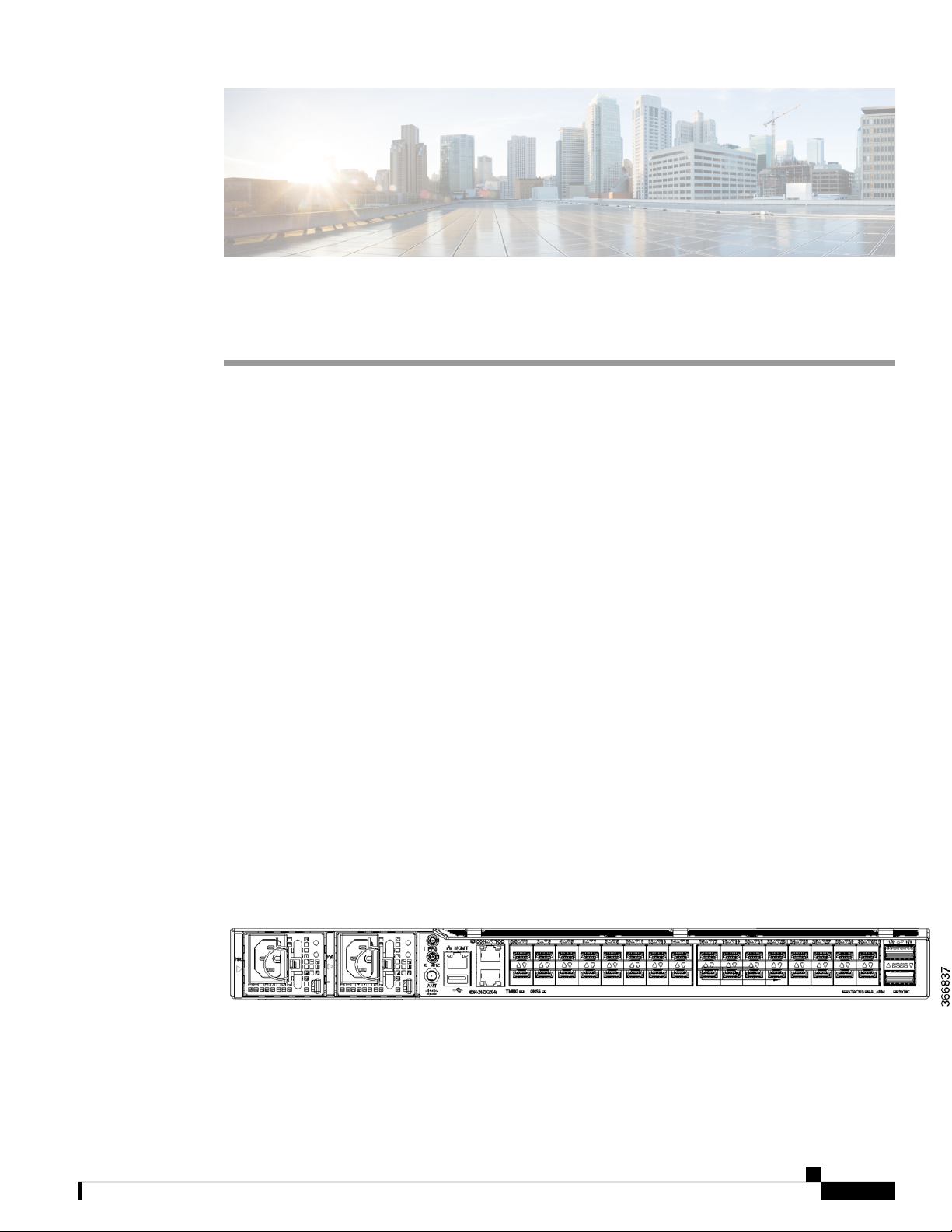
The Cisco NCS 540 1RU Router has the following hardware features:
• 24 x 10G SFP+ Ports
• Support DWDM & ZR Optics
• 8 x 25G SFP+ Ports
• 2 x 100G QSFP28 Ports
Figure 1: Cisco NCS 540 Device
Cisco NCS 540 Router Hardware Installation Guide
9
Page 16
Interface Naming
Note
All ports are color coded in the chassis for ease of access; for example, the 10G SFP+ Ports are in pink, the
25G SFP+ Ports are in yellow, and the 100G QSFP28 Ports are in green.
Interface Naming
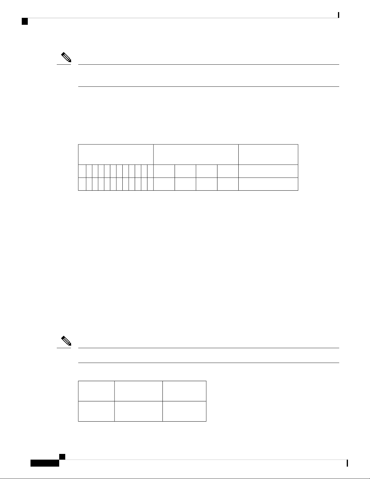
The following table shows the interface naming of the Cisco N540-24Z8Q2C-M ports:
Table 1: Port Numbering
Cisco NCS 540 Router Overview
1G/10G/25G Dual rate ports (SFP28)1G/10G Dual rate ports (SFP+)
40G/100G ports
(QSFP28)
1/0302826242220181614121086420/0
1/10/312927252321191715131197531
• Port 0 – 23: Dual rate ports, which can act as 1G or 10G also includes Copper and DWDM.
• Port Numbering: Gig/Te 0/0/0/<0-23>
• Port 24-31: Dual rate ports, which can act as 1G or 10G or 25G.
• Port Numbering: Gig/Te/Twe 0/0/0/<24-31>
• For the ports 24-31, a quad configuration is required to bring-up the ports as 1G/10G
• By default, all ports will come up as 25G
• Use the command hw-module quad 0 location 0/0/CPU0 mode to change to 10G
• Copper optics is not supported in these 8 ports, 24-31
• Do not combine 1G or 10G with 25G in a quad, quad 1: 24-27 and quad 2: 28-31
• Port 32-33: 40G or 100G ports.
• Port Numbering: Hu 0/0/1/<0-1>
Note
Dual-Rate functionality is supported only with the Supported SFP.
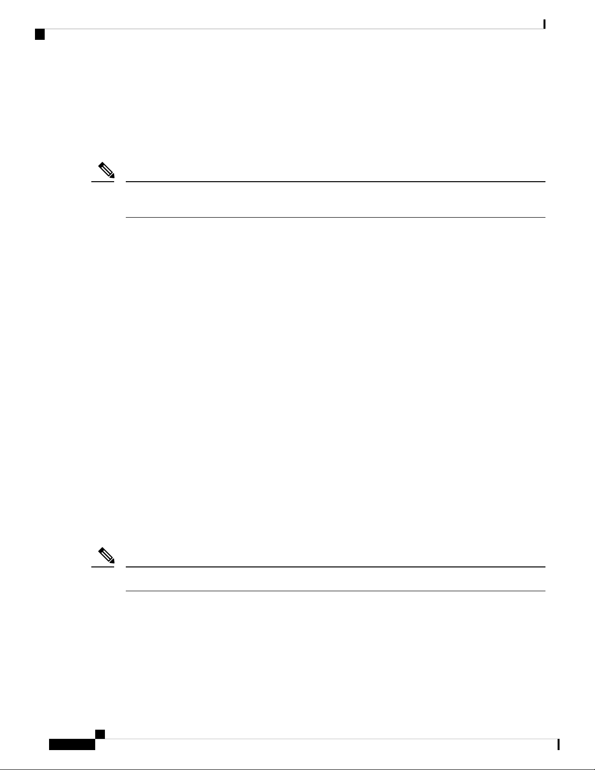
Table 2: Maximum Number of Inerfaces
Category
Port NumberMaximum
Interface
0/0 - 2324100ME
copper
Cisco NCS 540 Router Hardware Installation Guide
10
Page 17

Cisco NCS 540 Router Overview
Network Timing Interfaces
Category
Interface
10GE
8 / 16*25GE
1
*4x10GE or 4x25GE option
1
Network Timing Interfaces
• BITS input or output—The BITS interfaces support clock recovery from either a T1 at 1.544 MHz or an
E1 at 2.048 MHz, configurable by software. BITS interface is provided through a standard RJ-48 connector
on the front panel.
• 1PPS input or output and ToD input or output—This shielded RJ-45 interface is used for input or output
of time-of-day (ToD) and 1PPS pulses. ToD format includes both NTP and IEEE 1588-2008 time formats.
Port NumberMaximum
0/0 - 31321GE
0/0 - 31, 1/0 - 1*32 / 40*
0/24 - 31, 1/0 1*
1/0 - 1240GE
1/0 - 12100GE
The same RS422 pins for 1PPS and TOD are shared between input and output directions. The direction for
each can be independently configurable through software.
Use an SMB connector on the front panel for the following:
• GPS 10 Mhz input and output—10 MHz input for GPS Synchronization.
• GPS 1 PPS input and output—1 PPS input for GPS Synchronization.
External Alarm Inputs
The router supports four dry contact alarm inputs through an RJ-45 jack at the rear panel.
• Normally Open—indicates that no current flows through the alarm circuit and the alarm is generated
when the current is flowing.
Each alarm input can be provisioned as critical, major, or minor.
Console
The RS232 console port provides transmission (Tx), reception (Rx), and ground (Gnd).
Cisco NCS 540 Router Hardware Installation Guide
11
Page 18
USB Console
USB Console
A single USB 2.0 Type-A receptacle on the front panel of the router provides console access to ROMMON,
Cisco IOS-XE and diagnostics. While it uses the Type-A connector, it operates as a USB peripheral only for
connection to an external host computer. This interface requires the use of a Type-A to Type-A connector
instead of a standard USB cable.
Note
Use of the USB console is mutually exclusive of the RS232 console port. This interface requires the use of a
Type-A to Type-A USB cable.
Online Insertion and Removal
The router supports the following OIR operations:
• When an SFP is removed, there is no effect on traffic flowing on other ports.
Cisco NCS 540 Router Overview
• When an SFP is installed, the system initializes that port for operation that is based on the current
configuration. If the inserted SFP is incompatible with the current configuration for that port, the port
does not become operational until the configuration is updated.
• Both power supplies are installed and active, the load may be shared between them or a single PSU could
support the whole load. When a power supply is not working or the input cable is removed, the remaining
power supply takes the entire load without disruption.
Power Supply (N540-PWR400-A and N540-PWR400-D)
The Cisco NCS 540 router supports two AC or DC power supplies, which power the router. The second power
supply ensures redundancy in the system. Both power supplies support hot swapping capabilities.
Fan Assembly (N540-FAN)
Cisco NCS 540 Router comes with 4 individual fan modules. Fans are located at the rear panel and support
hot swapping. Fan flow is supported only on the forward direction from front to back.
Note
The system can function with a single fan failure but if more than one fan is faulty then the system shuts down.
Cisco NCS 540 Router Hardware Installation Guide
12
Page 19

Prepare for Installation
Before you install the Cisco NCS 540, you must prepare your site for the installation.
Preparing your site involves these tasks:
• General Precautions, on page 13
• Site Planning Checklist, on page 14
• Site Power Guidelines, on page 14
• Site Cabling Guidelines, on page 15
• Tools and Equipment, on page 16
• Prepare Your Location , on page 17
• Prepare Yourself , on page 18
• Prepare Rack for Router Installation, on page 18
• Unpack the Cisco NCS 540 Router, on page 19
General Precautions
Observe the following general precautions when using and working with your chassis:
CHAPTER 3
• Keep your system components away from radiators and heat sources, and do not block cooling vents.
• Do not spill food or liquids on your system components, and never operate the product in a wet
environment.
• Do not push any objects into the openings of your system components. Doing so can cause fire or electric
shock by shorting out interior components.
• Position system cables and power supply cable carefully. Route system cables and the power supply
cable and plug so that they are not stepped on or tripped over. Ensure that nothing is rests on your system
component cables or power cable.
• Do not modify power cables or plugs. Consult a licensed electrician or your power company for site
modifications. Always follow your local and national wiring rules.
• If you turn off your system to avoid damage of system components, wait at least 30 seconds before
turning it on again.
Cisco NCS 540 Router Hardware Installation Guide
13
Page 20

Site Planning Checklist
Site Planning Checklist
Use the following checklist to carry out all site planning tasks:
• The site meets environmental requirements.
• The site’s air conditioning system can compensate for the heat dissipation of the chassis.
• The floor space that the chassis occupies can support the weight of the system.
• Electrical service to the site complies with the safety with electricity requirements.
• The electrical circuit servicing the chassis complies with the power supply requirements.
• Console port wiring and cabling limitations have been considered in accordance to TIA/EIA-232F.
• The chassis Ethernet cabling distances are within prescribed limits.
• The equipment rack where the chassis is to be installed complies with prescribed requirements.
• When selecting rack location, safety, ease of maintenance, and proper airflow requirements have been
considered.
Prepare for Installation
Site Power Guidelines
The chassis has specific power and electrical wiring requirements. Adhering to these requirements ensures
reliable operation of the system. Follow these precautions and recommendations when planning your site
power for the chassis:
• The redundant power option provides a second, identical power supply to ensure uninterrupted power
supply.
• Connect each power supply to a separate input power source. Otherwise, it results in total power failure
to the system due to a fault in the external wiring or a tripped circuit breaker.
• To prevent loss of input power, ensure that the maximum load on each circuit is within the current ratings
of the wiring and the breakers.
• Check the power at your site before installation, and periodically after installation, to ensure that you are
receiving clean power. If necessary, install a power conditioner.
• Provide proper grounding to avoid personal injury and damage to the equipment due to power surges or
lightning striking power lines. The chassis ground must be attached to a central office or other interior
ground system.
Caution
This product requires short-circuit (overcurrent) protection to be provided as part of the building installation.
Install only in accordance with national and local wiring regulations.
Cisco NCS 540 Router Hardware Installation Guide
14
Page 21

Prepare for Installation
Note
The chassis installation must comply with all the applicable codes, and is approved for use with only copper
conductors. The ground bond-fastening hardware must be compatible and preclude loosening, deterioration,
and electrochemical corrosion of hardware and joined material. Attachment of the chassis ground to a central
office or other interior ground system must be made with a 6-AWG gauge wire copper ground conductor.
Electrical Circuit Requirements
Each chassis requires a dedicated electrical circuit. If you equip the device with dual-power feeds, provide a
separate circuit for each power supply to avoid compromising the power redundancy feature.
The chassis supports both DC source or an AC source. Ensure that equipment grounding is present and observe
power-strip ratings. Make sure that the total ampere rating of all the products plugged into the power strip
does not exceed 80% of the rating.
Site Cabling Guidelines
Electrical Circuit Requirements
This section contains guidelines for wiring and cabling at your site. When preparing your site for network
connections to the chassis, consider the type of cable that is required for each component and cable limitations.
Consider the distance limitations for signaling, electromagnetic interference (EMI), and connector compatibility.
Possible cable types are fiber, thick or thin coaxial, foil twisted-pair, or unshielded twisted-pair cabling.
Also, consider any additional interface equipment that you need, such as transceivers, hubs, switches, modems,
channel service units (CSU), or data service units (DSU).
Before you install the chassis, have on hand all additional external equipment and cables. For information
about ordering, contact a Cisco customer service representative.
The extent of your network and the distances between the network interface connections depend, in part, on
the following factors:
• Signal type
• Signal speed
• Transmission medium
The distance and rate limits that are referenced in the following sections are the IEEE-recommended maximum
speeds and distances for signaling purposes. Use this information as a guideline when planning your network
connections before installing the chassis.
If wires exceed the recommended distances, or if wires pass between buildings, give special consideration to
the possibility of a lightning strike in your vicinity. The electromagnetic pulse due to lightning or other
high-energy phenomena can easily couple enough energy into unshielded conductors to destroy electronic
devices. If you have had problems of this sort in the past, you may want to consult experts in electrical surge
suppression and shielding.
Asynchronous Terminal Connections
The chassis provides a console port to connect a terminal or computer for local console access. The port has
an RJ-45 connector and supports RS-232 asynchronous data with distance recommendations that are specified
in the IEEE RS-232 standard.
Cisco NCS 540 Router Hardware Installation Guide
15
Page 22

Interference Considerations
Interference Considerations
When wires are run for any significant distance, there is a risk of receiving stray signals on the wires as
interference. If interference signals are strong, it results in data errors or equipment damage.
The following sections describe the sources of interference and how to minimize their effects on the chassis.
Electromagnetic Interference
All the equipment that is powered by AC current can propagate electrical energy that can cause EMI and
possibly affect the operation of other equipment. The typical sources of EMI are equipment power cords and
power service cables from electric utilities.
Strong EMI can destroy the signal drivers and receivers in the chassis. It can even create an electrical hazard
by causing power surges through the power lines into installed equipment. These problems are rare, but could
be catastrophic.
To resolve these problems, you need specialized knowledge and equipment that could consume substantial
time and money. However, you can ensure that you have a properly grounded and shielded electrical
environment, paying special attention to the need for electrical surge suppression.
Prepare for Installation
Radio Frequency Interference
When electromagnetic fields act over a long distance, radio frequency interference (RFI) may be propagated.
Building wiring can often act as an antenna, receiving the RFI signals and creating more EMI on the wiring.
If you use a twisted-pair cable in your plant wiring with a good distribution of grounding conductors, the plant
wiring is unlikely to emit radio interference. If you exceed the recommended distances, use a high-quality
twisted-pair cable with one ground conductor for each data signal.
Lightning and AC Power Fault Interference
If signal wires exceed the recommended cabling distances, or if signal wires pass between buildings, you may
encounter a lightning strike on the chassis.
The electromagnetic pulse (EMP) generated by lightning or other high-energy phenomena can couple enough
energy into unshielded conductors and damage or destroy electronic equipment. For such problems, you must
consult with RFI and EMI experts to ensure adequate electrical surge suppression and shielding of signal
cables in your operating environment.
Tools and Equipment
You need the following tools and equipment to install and upgrade the device and its components:
• ESD-preventive cord and wrist strap
• Antistatic mat or antistatic foam
• Number 1 and Number 2 Phillips-head screwdrivers
• #12-24 pan-head screws to secure the device to the equipment rack.
• Cables for connecting to network ports (based on the configuration)
• Ethernet hub, switch, or PC with a network interface card for connecting to the Ethernet ports
• Console terminal that is configured for 9600 baud, 8 data bits, no parity, no flow control, and 1 stop bit.
• Console cable for connecting to the console port
Cisco NCS 540 Router Hardware Installation Guide
16
Page 23

Prepare for Installation
• Ratcheting torque screwdriver with a Phillips head that exerts up to 30-pound force per square inch
(0.02-kilograms force per square millimeter (kgf/mm2)) of pressure.
• Crimping tool as specified by the ground lug manufacturer
• Wire-stripping tools for stripping both 6 and 14-AWG wires
• Tape measure and level
• Ratcheting torque screwdriver with a Phillips head that exerts up to 15 inch-pounds (1.69 newton meters)
of torque for attaching the ground wire to the device.
Prepare Your Location
This section illustrates how the building that houses the chassis must be properly grounded to the earth ground.
Figure 2: Building with Rack Room Connected to Earth Ground
Prepare Your Location
Cisco NCS 540 Router Hardware Installation Guide
17
Page 24

Prepare Yourself
Prepare Yourself
This section illustrates how to prepare yourself before removing the chassis from the sealed antistatic bag.
The figures show how to wear the ESD strap around the wrist and how to connect the other end of the strap
to the ground. ESD wrist straps are the primary means of controlling static charge on personnel.
Figure 3: Wearing the ESD Strap
Note: These images are for only representation purposes. The chassis' actual appearance and size would vary.
Prepare for Installation
Prepare Rack for Router Installation
Install the chassis into a two-post standard rack with standard horizontal mounting rails. Before you mount
the chassis into the rack, we recommend that you do the following:
Step 1 Place the rack where you plan to install the chassis. Ensure that the rack is grounded to earth.
Step 2 Secure the rack to the floor.
Cisco NCS 540 Router Hardware Installation Guide
18
Page 25

Prepare for Installation
To bolt the rack to the floor, a floor bolt kit (also called an anchor embedment kit) is required. For information on bolting
the rack to the floor, consult a company that specializes in floor mounting kits (such as Hilti; see Hilti.com for details).
Make sure that floor mounting bolts are accessible, especially if an annual retorquing of bolts is required.
Unpack the Cisco NCS 540 Router
Before you begin
Ensure that there is sufficient room around the chassis pallet for unpacking.
Step 1 Remove the accessory tray and the packing material.
Step 2 Carefully set the packing material aside.
Unpack the Cisco NCS 540 Router
Tip
Note
Be sure to save the packaging in case you need to return any of the components products.
These images are for only representation purposes. The chassis' actual appearance and size would vary.
Cisco NCS 540 Router Hardware Installation Guide
19
Page 26

Unpack the Cisco NCS 540 Router
Figure 4: Unpacking the Device
Prepare for Installation
1
Foam end caps2Regular Slotted Container
(shipping box)
Front end of the product4Front corrugated cap3
Accessory tray6Back end of the product5
Cisco NCS 540 Router Hardware Installation Guide
20
Page 27

CHAPTER 4
Install the Device
Before you begin this task, ensure that you have read and understood the safety warnings in the Standard
Warning Statements section of the Safety Warnings handout topic.
Installing the Cisco NCS 540 involves these tasks:
• Rack-Mount, on page 21
• Ground the Device, on page 23
• Install the AC Power Cables, on page 24
• Install the DC Power Cables, on page 25
• Port Connection Guidelines , on page 26
• Connect to the Console Port, on page 27
• Connect to the Management Ethernet Port, on page 29
• Install and Remove Transceiver Modules, on page 30
• Connect Interface Ports, on page 38
• Maintain Transceivers and Optical Cables, on page 39
Rack-Mount
The device is shipped with rack mounting brackets that are to be secured on the sides of the device.
Caution
If the rack is on wheels, ensure that the brakes are engaged or the rack is otherwise stabilized.
Table 3: Cisco NCS 540 Router Rack-Mount Kit
Part DescriptionQuantity
Rack-mount brackets2
M4 x 0.7 x 6-mm Phillips flat-head screws8
2
M3 x 0.5 x 4-mm Phillips countersink screws3
2
Top cover or the NEBs kit is an optional accessory to improve the air flow, hence it may not be a part
of your standard package.
Cisco NCS 540 Router Hardware Installation Guide
21
Page 28

Rack-Mount
Step 1 (Optional) Attach the top cover or the NEBs kit by using the M3 screws to the chassis.
Step 2 Attach the two rack-mount brackets to the router as follows:
a) The router has port-side intake modules, position the router so that its ports are facing the cold aisle.
b) With the bracket ears facing the center of the chassis, position a front rack-mount bracket on the side of the chassis
so that its four holes are aligned to four screw holes on the side of the chassis.
c) Use four M4 screws to attach the bracket to the chassis.
d) Repeat Steps 1b and 1c with the other rack-mount bracket on the other side of the router.
Figure 5: Rack-mount brackets on Cisco NCS 540
Install the Device
Step 3 Install the router onto the 2-post rack as follows:
a) Lift and position the router into position between the two rack posts.
b) Move the router until the rack-mount brackets come in contact with the two rack posts.
c) Hold the chassis at level and have another while the second person insert two screws (12-24 or 10-32, depending on
the rack type) in each of the two rack-mount brackets (using a total of four screws) and into the cage nuts or threaded
holes in the vertical rack-mounting rails.
d) Tighten the 10-32 screws to 20 in-lb (2.26 N.m) or tighten the 12-24 screws to 30 in-lb (3.39 N.m).
Cisco NCS 540 Router Hardware Installation Guide
22
Page 29

Install the Device
Ground the Device
Before you begin this task, ensure that you have read and understood the safety warnings in the Preventing
ESD Damage section of the Safety Warnings handout topic.
Before you connect the power or turn on the power to the device, you must provide an adequate device ground
(earth) connection to your device.
This section describes how to ground the device. The grounding lug location is on the back panel of the device.
Step 1 Verify that the ground cable is connected to the top of the rack and according to local site practice.
Figure 6: Cisco NCS 540 Ground Lug
Ground the Device
2Grounding lug1
Step 2 Attach one end of the shelf ground cable (#6 AWG cable) to the ground point on the rear of the chassis using the specified
dual-hole lug connector.
a) Use a wire-stripping tool to remove approximately 0.75 inches (19 mm) of the covering from the end of the grounding
cable.
b) Insert the stripped end of the grounding cable into the open end of the grounding lug.
c) Use the crimping tool to secure the grounding cable in the grounding lug.
d) Remove the adhesive label from the grounding pad on the chassis.
e) Place the grounding lug against the grounding pad so that there is solid metal-to-metal contact, and insert the two
M4 screws with washers through the holes in the grounding lug and into the grounding pad.
f) Ensure that the lug and cable do not interfere with other equipment.
g) Prepare the other end of the grounding cable and connect it to an appropriate grounding point in your site to ensure
adequate earth ground.
M4 x 12 mm pan-head
screws
Cisco NCS 540 Router Hardware Installation Guide
23
Page 30

Install the Device
Install the AC Power Cables
Install the AC Power Cables
To install the AC power cables in the power supply slots:
Step 1 Plug the power supply cord in the power supply module.
Step 2 Insert the power supply cord into the tie [1] and tighten the tie around the power supply cord as shown in [2] in the figure
below.
Figure 7: Attach the AC Power Tie-and-Clip Cord
Activate an AC Power Supply Module
Perform the following procedure to activate an AC power supply:
Step 1 Plug the power cord into the power supply.
Step 2 Connect the other end of the power cord to an AC-input power source.
Cisco NCS 540 Router Hardware Installation Guide
24
Page 31

Install the Device
Install the DC Power Cables
Step 3 Verify power supply operation by checking if the respective power supply front panel LED (PS0 or PS1) is green.
Step 4 If the LEDs indicate a power problem, see Troubleshooting for troubleshooting information.
Step 5 If you are connecting a redundant AC power supply, repeat these steps for the second power source.
Note
If you are connecting a redundant AC power supply, ensure that each power supply is connected to a separate
power source in order to prevent power loss in the event of a power failure.
Install the DC Power Cables
Note
When installing DC power supply, use 14 AWG, 90°C wires. Always ensure that the building’s installation
for short-circuit (overcurrent) protection does not exceed 15A.
Note
The DC connector or terminal block has an inbuilt screw and cage nut to which a torque of 1.3 to 1.8 N-m
can be applied.
Figure 8: DC Connector With Inbuilt Screw
0.27 inchesC0.97 inchesA
0.81 inchesM0.31 inchesB
To attach the DC power supplies:
Step 1 Locate the terminal block plug.
Step 2 Insert the DC-input power source wires into the terminal block plug.
Step 3 Attach the DC supply wires using the designated screws.
Step 4 Use a ratcheting torque screwdriver to torque the terminal block plug captive screw. See the following figure.
Cisco NCS 540 Router Hardware Installation Guide
25
Page 32

Activate a DC Power Supply Module
Figure 9: Attach the DC Power Supply Wires
Install the Device
Activate a DC Power Supply Module
Perform the following procedure to activate a DC power supply:
Step 1 Remove the tape from the circuit-breaker router handle, and restore power by moving the circuit-breaker router handle
to the On (|) position.
Step 2 Verify power supply operation by checking if the respective power supply front panel LED (PS0 or PS1) is green.
Step 3 If the LEDs indicate a power problem, see Troubleshooting.
Step 4 If you are connecting a redundant DC power supply, repeat these steps for the second power source.
Note
If you are connecting a redundant DC power supply, ensure that each power supply is connected to a separate
power source in order to prevent power loss in the event of a power failure.
Port Connection Guidelines
Depending on the chassis and installed line cards, you can use Quad Small Form-Factor Pluggable Plus
(QSFP+), QSFP28, SFP, SFP+, and RJ-45 connectors to connect the ports on the line cards to other network
devices.
Cisco NCS 540 Router Hardware Installation Guide
26
Page 33

Install the Device
Connect to the Console Port
To prevent damage to the fiber-optic cables, Cisco recommends that you keep the transceivers disconnected
from their fiber-optic cables when installing the transceiver in the line card. Before removing a transceiver
from the router, remove the cable from the transceiver.
To maximize the effectiveness and life of your transceivers and optical cables, do the following:
• Wear an ESD-preventative wrist strap that is connected to an earth ground whenever handling transceivers.
The router is typically grounded during installation and provides an ESD port to which you can connect
your wrist strap.
• Do not remove and insert a transceiver more often than is necessary. Repeated removals and insertions
can shorten its useful life.
• Keep the transceivers and fiber-optic cables clean and dust free to maintain high signal accuracy and to
prevent damage to the connectors. Attenuation (loss of light) is increased by contamination and should
be kept below 0.35 dB.
• Clean these parts before installation to prevent dust from scratching the fiber-optic cable ends.
• Clean the connectors regularly; the required frequency of cleaning depends upon the environment.
In addition, clean connectors when they are exposed to dust or accidentally touched. Both wet and
dry cleaning techniques can be effective; refer to your site's fiber-optic connection cleaning
procedures.
• Do not touch the ends of connectors. Touching the ends can leave fingerprints and cause other
contamination.
• Inspect routinely for dust and damage. If you suspect damage, clean and then inspect fiber ends under a
microscope to determine if damage has occurred.
Warning
Invisible laser radiation may be emitted from disconnected fibers or connectors. Do not stare into beams or
view directly with optical instruments.
Connect to the Console Port
Before you create a network management connection for the router or connect the router to the network, you
must create a local management connection through a console terminal and configure an IP address for the
router. You also can use the console to perform the following functions (each of which can be performed
through the management interface after you make that connection):
• Configure the router using the command-line interface (CLI).
• Monitor network statistics and errors.
• Configure Simple Network Management Protocol (SNMP) agent parameters.
• Download software updates.
The system console port is an RJ-45 receptacle for connecting a data terminal to perform the initial configuration
of Cisco NCS 540 fixed-port chassis. The console cable is shipped with the hardware.
Cisco NCS 540 Router Hardware Installation Guide
27
Page 34

Connect to the Console Port
Figure 10: Console Port
Follow this procedure to connect a data terminal to the console port.
Before you begin
Install the Device
• The router must be fully installed in its rack, connected to a power source, and grounded.
• The necessary cabling for the console, management, and network connections must be available.
• An RJ-45 rollover cable and DB9F/RJ-45 adapter are provided in the router accessory kit.
• Network cabling should already be routed to the location of the installed router.
Step 1 Set your terminal to these operational values: 115200 bps, 8 data bits, no parity, and 2 stop bits.
Step 2 Attach the terminal end of the cable to the interface port on the data terminal.
Step 3 Attach the other end of the cable to the console port.
Following table represents the RJ-45 cable pin-out information.
Table 4: RJ-45 Straight-through Cable Pin-outs
SignalRJ-45 Pin
—1
—2
Tx3
Ground (GND)4
GND5
Rx6
—7
Cisco NCS 540 Router Hardware Installation Guide
28
Page 35

Install the Device
SignalRJ-45 Pin
—8
Connect to the Management Ethernet Port
The management Ethernet port provides out-of-band management, which enables you to use the command-line
interface (CLI) to manage the router by its IP address. This port uses a 10/100/1000 Ethernet connection with
an RJ-45 interface.
Note
To prevent an IP address conflict, do not connect the management Ethernet port until the initial configuration
is complete.
To connect cables to the system management port, attach Category 5 cables directly to the RJ-45 receptacle
on the management Ethernet port.
Figure 11: Console Port
Connect to the Management Ethernet Port
Note
To comply with GR-1089-CORE, the intra-building port(s) of the equipment must use shielded intra-building
cabling or wiring that is grounded at both ends.
Before you begin
You must complete initial router configuration.
Step 1 Plug the cable directly into the RJ-45 receptacle.
Step 2 Connect the network end of your RJ-45 cable to a switch, hub, repeater, or other external equipment.
Cisco NCS 540 Router Hardware Installation Guide
29
Page 36

Install and Remove Transceiver Modules
Install and Remove Transceiver Modules
Install and Remove SFP Modules
Before you remove or install an SFP or SFP+ module, read the installation information in this section.
Install the Device
Warning
Caution
Invisible laser radiation may be emitted from disconnected fibers or connectors. Do not stare into beams or
view directly with optical instruments. Statement 1051
Protect the line card by inserting a clean SFP/SFP+ module cage cover, shown in the figure below, into the
optical module cage when there is no SFP or SFP+ module installed.
Figure 12: SFP/SFP+ Module Cage Cover
30
Caution
Caution
Protect the SFP or SFP+ modules by inserting clean dust covers into them after the cables are removed. Be
sure to clean the optic surfaces of the fiber cables before you plug them back into the optical ports of another
module. Avoid getting dust and other contaminants into the optical ports of your SFP or SFP+ modules,
because the optics do not work correctly when obstructed by dust.
We strongly recommended that you do not install or remove the SFP or SFP+ module with fiber-optic cables
attached to it because of the potential of damaging the cable, the cable connector, or the optical interfaces in
the module. Disconnect all cables before removing or installing an SFP or SFP+ module. Removing and
inserting a module can shorten its useful life, so you should not remove and insert modules any more than is
absolutely necessary.
Cisco NCS 540 Router Hardware Installation Guide
Page 37

Install the Device
Note
When installing an SFP or SFP+ module, you should hear a click as the triangular pin on the bottom of the
module snaps into the hole in the receptacle. The click indicates that the module is correctly seated and secured
in the receptacle. Verify that the modules are completely seated and secured in their assigned receptacles on
the line card by firmly pushing on each SFP or SFP+ module.
Bale Clasp SFP or SFP+ Module
The bale clasp SFP or SFP+ module has a clasp that you use to remove or install the module (see the figure
below).
Figure 13: Bale Clasp SFP or SFP+ Module
Bale Clasp SFP or SFP+ Module
Install a Bale Clasp SFP or SFP+ Module
To install this type of SFP or SFP+ module, follow these steps:
Step 1 Attach an ESD-preventive wrist or ankle strap and follow its instructions for use.
Step 2 Close the bale clasp before inserting the SFP module.
Step 3 Line up the SFP module with the port and slide it into the port (see the figure below).
Figure 14: Installing a Bale Clasp SFP Module into a Port
Note
When installing an SFP or SFP+ module, you should hear a click as the triangular pin on the bottom of the SFP
module snaps into the hole in the receptacle. This click indicates that the module is correctly seated and secured
in the receptacle. Verify that the SFP modules are completely seated and secured in their assigned receptacles
on the line card by firmly pushing on each SFP module.
Cisco NCS 540 Router Hardware Installation Guide
31
Page 38

Install the Device
Remove a Bale Clasp SFP or SFP+ Module
Remove a Bale Clasp SFP or SFP+ Module
To remove this type of SFP or SFP+ module, follow these steps:
Step 1 Attach an ESD-preventive wrist or ankle strap and follow its instructions for use.
Step 2 Disconnect and remove all interface cables from the ports; note the current connections of the cables to the ports on the
line card.
Step 3 Open the bale clasp on the SFP module with your index finger, as shown in the figure below. If the bale clasp is obstructed
and you cannot use your index finger to open it, use a small flat-blade screwdriver or other long, narrow instrument to
open the bale clasp.
Step 4 Grasp the SFP module between your thumb and index finger and carefully remove it from the port, as shown in the figure
below.
Note
This action must be performed during your first instance. After all the ports are populated, this may not be
possible.
Cisco NCS 540 Router Hardware Installation Guide
32
Page 39

Install the Device
Figure 15: Removing a Bale Clasp SFP or SFP+ Module
Remove a Bale Clasp SFP or SFP+ Module
Step 5 Place the removed SFP module on an antistatic mat, or immediately place it in a static shielding bag if you plan to return
it to the factory.
Step 6 Protect your line card by inserting a clean SFP module cage covers into the optical module cage when there is no SFP
module installed.
Cisco NCS 540 Router Hardware Installation Guide
33
Page 40

Install and Remove QSFP+/QSFP28 Transceiver Modules
Install and Remove QSFP+/QSFP28 Transceiver Modules
This section provides the installation, cabling, and removal instructions for the 40-Gigabit Quad Small
Form-Factor Pluggable Plus (QSFP+) and 100 Gigabit (QSFP28) transceiver modules. The modules are
hot-swappable input/output (I/O) devices that connect the system’s module port electrical circuitry with either
a copper or a fiber-optic network.
Overview
The 40-Gigabit (GE) QSFP+ and 100 Gigabit (QSFP28) transceiver module is a hot-swappable, parallel
fiber-optical module with 4 independent optical transmit and receive channels. These channels can terminate
in another 40-Gigabit QSFP+ transceiver, or the channels can be broken out to 4 separate 10-Gigabit SFP+
transceivers. The QSFP+ transceiver module connects the electrical circuitry of the system with an optical
external network.
The following figure shows the 40-Gigabit optical QSFP+ transceiver. The transceiver is used primarily in
short reach applications in switches, routers, and data center equipment where it provides higher density than
SFP+ modules. The 100-Gigabit optical QSFP28 transceiver is similar to the 40-Gigabit optical QSFP
transceiver.
Figure 16: 40-Gigabit QSFP+ Transceiver Module (Optical)
Install the Device
1
transceiver body
Bail-clasp latch2
Required Tools and Equipment
You need these tools to install the 40-Gigabit QSFP+ / 100-Gigabit QSFP28 transceiver modules:
• Wrist strap or other personal grounding device to prevent ESD occurrences.
• Antistatic mat or antistatic foam to set the transceiver on.
• Fiber-optic end-face cleaning tools and inspection equipment.
For information on inspecting and cleaning fiber-optic connections, see Maintain Transceivers and Optical
Cables.
Install the 100-Gigabit Transceiver Module
The QSFP+ or QSFP28 transceiver module can have either a bail-clasp latch or a pull-tab latch. Installation
procedures for both types of latches are provided.
340GBASE QSFP+
Electrical connection to
the module circuitry
Cisco NCS 540 Router Hardware Installation Guide
34
Page 41

Install the Device
Install the 100-Gigabit Transceiver Module
Caution
The QSFP+ or QSFP28 transceiver module is a static-sensitive device. Always use an ESD wrist strap or
similar individual grounding device when handling QSFP+ or QSFP28 transceiver modules or coming into
contact with system modules.
To install an QSFP+ or QSFP28 transceiver module, follow these steps:
Step 1 Attach an ESD wrist strap to yourself and a properly grounded point on the chassis or the rack.
Step 2 Remove the QSFP+ or QSFP28 transceiver module from its protective packaging.
Step 3 Check the label on the QSFP+ or QSFP28 transceiver module body to verify that you have the correct model for your
network.
Step 4 For optical QSFP+ or QSFP28 transceiver modules, remove the optical bore dust plug and set it aside.
Step 5 For QSFP+ or QSFP28 transceiver modules equipped with a pull-tab, hold the transceiver so that the identifier label is
on the top.
Step 6 For QSFP+ or QSFP28 transceiver modules equipped with a bail-clasp latch, keep the bail-clasp aligned in a vertical
position.
Step 7 Align the QSFP+ or QSFP28 transceiver module in front of the module’s transceiver socket opening and carefully slide
the QSFP+ or QSFP28 transceiver into the socket until the transceiver makes contact with the socket electrical connector
(see the figure below).
Figure 17: Installing the 100-Gigabit QSFP28 Transceiver Module (Optical Transceiver Equipped with a Bail-Clasp Latch Shown)
Step 8 Press firmly on the front of the QSFP+ or QSFP28 transceiver module with your thumb to fully seat the transceiver in
the module’s transceiver socket (see the below figure).
Caution
If the latch is not fully engaged, you might accidentally disconnect the QSFP+ or QSFP28 transceiver module.
Cisco NCS 540 Router Hardware Installation Guide
35
Page 42

Attach the Optical Network Cable
Figure 18: Seating the 100-Gigabit QSFP28 Transceiver Module (Optical Transceiver Equipped with a Bail-Clasp Latch Shown)
Install the Device
Step 9 For optical QSFP+ or QSFP28 transceiver modules, reinstall the dust plug into the QSFP+ or QSFP28 transceivers optical
bore until you are ready to attach the network interface cable. Do not remove the dust plug until you are ready to attach
the network interface cable.
Attach the Optical Network Cable
Before you begin
Before you remove the dust plugs and make any optical connections, follow these guidelines:
• Keep the protective dust plugs installed in the unplugged fiber-optic cable connectors and in the transceiver
optical bores until you are ready to make a connection.
• Inspect and clean the MPO connector end faces just before you make any connections.
• Grasp the MPO connector only by the housing to plug or unplug a fiber-optic cable.
Note
40-Gigabit QSFP+ or QSFP28 transceiver modules are keyed to prevent incorrect insertion.
Cisco NCS 540 Router Hardware Installation Guide
36
Page 43

Install the Device
Remove the 100-Gigabit QSFP28 Transceiver Module
Note
The multiple-fiber push-on (MPO) connectors on the optical QSFP+ or QSFP28 transceivers support network
interface cables with either physical contact (PC) or ultra-physical contact (UPC) flat polished face types.
The MPO connectors on the optical QSFP+ or QSFP28 transceivers do not support network interface cables
with an angle-polished contact (APC) face type.
Step 1 Remove the dust plugs from the optical network interface cable MPO connectors. Save the dust plugs for future use.
Step 2 Inspect and clean the MPO connector’s fiber-optic end faces.
Step 3 Remove the dust plugs from the QSFP+ or QSFP28 transceiver module optical bores.
Step 4 Immediately attach the network interface cable MPO connectors to the QSFP+ or QSFP28 transceiver module (see the
figure below).
Figure 19: Cabling a 40-Gigabit QSFP+ or QSFP28 Transceiver Module
Remove the 100-Gigabit QSFP28 Transceiver Module
Caution
Step 1 For optical QSFP+ or QSFP28 transceiver modules, disconnect the network interface cable from the QSFP+ or QSFP28
transceiver connector.
Step 2 For QSFP+ or QSFP28 transceiver modules equipped with a bail-clasp latch (see the below figure, top view):
a) Pivot the bail-clasp down to the horizontal position.
b) Immediately install the dust plug into the transceivers optical bore.
c) Grasp the sides of the QSFP+ or QSFP28 transceiver and slide it out of the module socket.
Step 3 For QSFP+ or QSFP28 transceivers equipped with a pull tab latch (see the below figure, bottom view):
a) Immediately install the dust plug into the transceiver’s optical bore.
b) Grasp the tab and gently pull to release the transceiver from the socket.
The QSFP+ or QSFP28 transceiver module is a static-sensitive device. Always use an ESD wrist strap or
similar individual grounding device when handling QSFP+ or QSFP28 transceiver modules or when coming
into contact with modules.
To remove a QSFP+ or QSFP28 transceiver module, follow these steps:
Cisco NCS 540 Router Hardware Installation Guide
37
Page 44

Connect Interface Ports
c) Slide the transceiver out of the socket.
Figure 20: Removing the 100-Gigabit QSFP28 Transceiver Module
Install the Device
Step 4 Place the QSFP+ or QSFP28 transceiver module into an antistatic bag.
Connect Interface Ports
You can connect optical interface ports on line cards with other devices for network connectivity.
Connect a Fiber-Optic Port to the Network
Depending on the line card model that you are using, you can use either QSFP+ or QSFP28 transceivers.
Some transceivers work with fiber-optic cables that you attach to the transceivers and other transceivers work
with pre-attached copper cables. When installing fiber-optic cables for a port, you must install SFP transceivers
for 1-Gigabit optical ports or install SFP+ transceivers for 10-Gigabit optical ports or QSFP+ transceivers for
100-Gigabit ports before installing the fiber-optic cable in the transceivers.
Caution
Removing and installing a transceiver can shorten its useful life. Do not remove and insert transceivers any
more than is absolutely necessary. We recommended that you disconnect cables before installing or removing
transceivers to prevent damage to the cable or transceiver.
Disconnect Optical Ports from the Network
When you need to remove fiber-optic transceivers, you must first remove the fiber-optic cables from the
transceiver before you remove the transceiver from the port.
Cisco NCS 540 Router Hardware Installation Guide
38
Page 45

Install the Device
Maintain Transceivers and Optical Cables
Transceivers and fiber-optic cables must be kept clean and free of dust to maintain high signal accuracy and
to prevent damage to the connectors. Attenuation (loss of light) is increased by contamination and should be
below 0.35 dB.
Consider the following maintenance guidelines:
• Transceivers are static sensitive. To prevent ESD damage, wear an ESD-preventative wrist strap that is
connected to the grounded chassis.
• Do not remove and insert a transceiver any more than is necessary. Repeated removals and insertions
can shorten its useful life.
• Keep all optical connections covered when not in use. Clean them before use to prevent dust from
scratching the fiber-optic cable ends.
• Do not touch the ends of connectors. Touching the ends would leave fingerprints and cause other
contamination.
Maintain Transceivers and Optical Cables
• Clean the connectors regularly; the required frequency of cleaning depends upon the environment. In
addition, clean connectors if they are exposed to dust or have been accidentally touched. Both wet and
dry cleaning techniques can be effective; refer to your site's fiber-optic connection cleaning procedures.
• Inspect routinely for dust and damage. Clean and then inspect fiber ends under a microscope to determine
whether any damage has occurred.
Cisco NCS 540 Router Hardware Installation Guide
39
Page 46

Maintain Transceivers and Optical Cables
Install the Device
Cisco NCS 540 Router Hardware Installation Guide
40
Page 47

Configure the Device
Before you begin this task, ensure that you have read and understood the safety warnings in the Safety with
Electricity section of the Safety Warnings handout topic.
Configuring the Cisco NCS 540 involves these tasks:
• Create the Initial Router Configuration, on page 41
• Verify Device Installation, on page 43
Create the Initial Router Configuration
You must assign an IP address to the router management interface so that you can then connect the router to
the network.
When you initially power up the router, it boots up and asks a series of questions to configure the router. To
enable you to connect the router to the network, you can use the default choices for each configuration except
for the IP address, which you must provide.
CHAPTER 5
Note
Be aware of the router's unique name to identify it among the devices in the network.
Before you begin
• A console device must be connected with the router.
• The router must be connected to a power source.
• Determine the IP address and netmask needed for the Management interfaces: MgmtEth0/RP0/CPU0/0
and MgmtEth0/RP1/CPU0/0:
Step 1 Power up the router.
The LEDs on each power supply light up (green) when the power supply units are sending power to the router, and the
software asks you to specify a password to use with the router.
Step 2 When the system is booted up for the first time, a new username and a password is to be created. The following prompt
appears:
Cisco NCS 540 Router Hardware Installation Guide
41
Page 48

Create the Initial Router Configuration
!!!!!!!!!!!!!!!!!!!! NO root-system username is configured. Need to configure root-system username.
!!!!!!!!!!!!!!!!!!!!
--- Administrative User Dialog ---
Enter root-system username:
% Entry must not be null.
Enter root-system username: root
Enter secret:
Use the 'configure' command to modify this configuration.
User Access Verification
Username: root
Password:
RP/0/RP0/CPU0:ios#
Step 3 Enter a new password to use for this router.
Configure the Device
The software checks the security strength of your password and rejects your password if it is not considered to be a strong
password. To increase the security strength of your password, make sure that it adheres to the following guidelines:
• At least eight characters
• Minimizes or avoids the use of consecutive characters (such as "abcd")
• Minimizes or avoids repeating characters (such as "aaa")
• Does not contain recognizable words from the dictionary
• Does not contain proper names
• Contains both uppercase and lowercase characters
• Contains numbers as well as letters
Note
Tip
Clear text passwords cannot include the dollar sign ($) special character.
If a password is trivial (such as a short, easy-to-decipher password), the software rejects the password
configuration. Be sure to configure a strong password as explained in this step. Passwords are case sensitive.
If you enter a strong password, the software asks you to confirm the password.
Step 4 Reenter the password.
When you enter the same password, the software accepts the password .
Step 5 Enter the IP address for the management interface.
Step 6 Enter a network mask for the management interface.
Step 7 The software asks if you need to edit the configuration. Enter no to not edit the configuration.
Step 8 The software asks if you need to save the configuration. Enter yes to save the configuration.
Cisco NCS 540 Router Hardware Installation Guide
42
Page 49

Configure the Device
Verify Device Installation
After installing the Cisco NCS 540 Router, you can use the show commands to verify the installation and
configuration. If any issue is detected, take corrective action before making further configurations.
Step 1 show inventory
Example:
#show inventory
Displays information about the field replaceable units (FRUs), including product IDs, serial numbers, and version IDs.
Step 2 show environment
Example:
#show environment
Displays all environment-related router information.
Verify Device Installation
Step 3 show environment temperature
Example:
#show environment temperature
Displays temperature readings for card temperature sensors. Each system controller, route processor, line card, and fabric
card has temperature sensors with two thresholds:
• Minor temperature threshold: when a minor threshold is exceeded, a minor alarm occurs and the following actions
occur for all four sensors:
• System messages displayed
• SNMP notifications (if configured) sent
• Log environmental alarm event triggered (can be reviewed by running the show alarm command).
• Major temperature threshold: when a major threshold is exceeded, a major alarm occurs and the following actions
occur:
• For sensors 1, 3, and 4 (outlet and onboard sensors), the following actions occur:
• System messages displayed
• SNMP notifications (if configured) sent
• Log environmental alarm event triggered (can be reviewed by running the show alarm command).
• For sensor 2 (intake sensor), the following actions occur:
• If the threshold is exceeded in a switching card, only that card is shut down.
• If the threshold is exceeded in an active route processor card with HA-standby or standby present, only
that route processor card is shut down and the standby route processor card takes over.
• If you do not have a standby route processor card in your router, you have up to 2 minutes to decrease the
temperature. During this interval, the software monitors the temperature every 5 seconds and continuously
sends system messages as configured.
Cisco NCS 540 Router Hardware Installation Guide
43
Page 50

Verify Device Installation
Configure the Device
Note
We recommend that you install dual route processor cards. If you are using a router without dual route processor
cards, we recommend that you immediately replace the fan card even if just one fan is not working.
Step 4 hw-module location <loc> shutdown or [no] hw-module shutdown location <loc>
Example:
#hw-module location <loc> shutdown
Powers up or shuts down a card gracefully.
Step 5 show environment power
Example:
#show environment power
Displays the power usage information for the entire router.
Step 6 show environment voltage
Example:
#show environment voltage
Displays the voltage for the entire router.
Step 7 show environment current
Example:
#show environment current
Displays the current environment status.
Step 8 show environment fan
Example:
#show environment fan
Displays the status of the fan trays.
Cisco NCS 540 Router Hardware Installation Guide
44
Page 51

Replace Fan Module and Power Supply
Before you begin this task, ensure that you have read and understood the safety warnings in the Safety with
Electricity section of the Safety Warnings handout topic.
Replacing the Cisco NCS 540 involves these tasks:
• Replace Fan Module, on page 45
• Replace Power Supply, on page 46
Replace Fan Module
CHAPTER 6
Caution
Step 1 Unscrew the captive thumbscrew at the front of the fan tray.
If you cannot replace a fan tray within three minutes, we recommend that you leave it in the chassis until you
are prepared to replace it within that specified time limit.
Note
If you remove more than one fan tray at a time during operations, the router allows up to 2 minutes of operations
before shutting down, unless you replace extra missing fan trays within that time. If the router senses an over
temperature condition when multiple fan trays are removed, the shutdown can occur in less than 2 minutes.
Cisco NCS 540 Router Hardware Installation Guide
45
Page 52

Replace Power Supply
Figure 21: Remove Fan Tray from the Chassis
Replace Fan Module and Power Supply
Step 2 Pull the fan tray to remove the fan tray to be replaced.
Step 3 Hold the fan module with the LED and PID label at the top.
Step 4 Align the fan module to the open fan tray slot in the chassis and press the module all the way into the slot until the left
and right latches click and lock on the chassis.
Step 5 If the chassis is powered on, listen for the fans. You should immediately hear them in operation. If you do not hear them,
ensure that the fan module is inserted completely in the chassis.
Step 6 Verify that the fan module LED is green. If the LED is not green, one or more fans are faulty.
Replace Power Supply
The router provides the choice of two different power supplies:
• DC power—The DC power supply uses 2-position terminal block-style connector with positive
latching/securing and labeled connections for +24/48V, GRD, -24/48V. The terminal block connector
is of suitable size to carry the appropriate AWG wire size to handle the input current of the power supply.
No ON/OFF switch is provided.
• AC power—The AC power supply has an IEC 320-type power receptacle and a 15 Amp service connector.
You can use standard right angle power cords with the AC power supply. The power supply includes a
power cord retainer. No ON/OFF switch is provided.
You can install dual power supplies for redundancy.
Cisco NCS 540 Router Hardware Installation Guide
46
Page 53

Replace Fan Module and Power Supply
Note
Products that have an AC power connection are required to have an external surge protective device (SPD)
provided as part of the building installation to comply with the Telcordia GR-1089 NEBS standard for
electromagnetic compatibility and safety.
Remove the DC Power Supply Module
Caution
Do not use interface module and power supply ejector handles to lift the chassis; using the handles to lift the
chassis can deform or damage the handles.
Remove the DC Power Supply Module
This section provides information about removing and replacing the DC power supply.
Warning
Warning
Step 1 Before servicing the power supply, switch off the circuit breaker in your equipment area. As an additional precaution,
tape the circuit-breaker switch in the Off position.
Step 2 Slip on the ESD-preventive wrist strap that was included in the accessory kit.
Step 3 Switch the power supply circuit-breaker switch to the Off (O) position.
Step 4 Pull the terminal block plug connector out of the terminal block head in the power supply. See the following figure.
Step 5 Loosen the captive screws on the DC power supply.
Step 6 Grasp the power supply handle. Simultaneously press the power supply lock towards the left and pull the power supply
out from the chassis while supporting it with the other hand.
Before performing any of the following procedures, ensure that power is removed from the DC circuit.
Statement 1003
Only trained and qualified personnel should be allowed to install, replace, or service this equipment. Statement
1030
Follow these steps to remove and replace the DC power supply:
Install the DC Power Supply Module
This equipment is suitable for installation in Network Telecommunications Facilities and locations where the
NEC applies.
This equipment is suitable for installations utilizing the Common Bonding Network (CBN).
The grounding architecture of this product is DC-Isolated (DC-I) for DC-powered products. DC-powered
products have a nominal operating DC voltage of 48 VDC.
Perform the following procedure to install the power supply module:
Cisco NCS 540 Router Hardware Installation Guide
47
Page 54

Replace Fan Module and Power Supply
Remove the AC Power Supply Module
Step 1 Ensure that the system (earth) ground connection has been made. See the following figure.
Step 2 If necessary, remove the blank power supply filler plate from the chassis power supply bay opening by loosening the
captive installation screws.
Step 3 Verify that power to the DC circuit connected to the power supply you are installing is off. To ensure that power has been
removed from the DC circuits, locate the circuit breakers for the DC circuits, switch the circuit breakers to the OFF
position, and tape the circuit-breaker switches in the OFF position.
Step 4 Grasp the power supply handle with one hand. Place your other hand underneath the power supply. Slide the power
supply into the power supply bay. Make sure that the power supply is fully seated in the bay.
Step 5 Tighten the captive installation screws of the power supply. The recommended maximum torque is 5.5 in.-lb (0.62 N-m).
Figure 22: Install DC Power Supply Module
Remove the AC Power Supply Module
This section describes how to remove and replace the AC power supply.
Warning
Warning
Warning
48
When you install the unit, the ground connection must always be made first and disconnected last. Statement
1046
Only trained and qualified personnel should be allowed to install, replace, or service this equipment. Statement
1030
Installation of the equipment must comply with local and national electrical codes. Statement 1074
Follow these steps to remove and replace the AC power supply:
Cisco NCS 540 Router Hardware Installation Guide
Page 55

Replace Fan Module and Power Supply
Install the AC Power Supply Module
Step 1 Disconnect the power cord from the power source. Do not touch any metal on the power cord when it is still connected
to the power supply.
Step 2 Loosen the tie and remove the power cord from the tie-and holder.
Step 3 Remove the power cord from the power connection on the power supply. Do not touch the metal prongs embedded in
the power supply.
Step 4 Grasp the power supply handle. Simultaneously press the power supply lock towards the left and pull the power supply
out from the chassis while supporting it with the other hand.
Install the AC Power Supply Module
Follow these steps to install the AC power supply module:
Step 1 Ensure that the system (earth) ground connection has been made.
Step 2 If necessary, remove the blank power supply filler plate from the chassis power supply bay opening by loosening the
captive installation screws.
Step 3 Grasp the power supply handle with one hand. Place your other hand underneath the power supply. Slide the power
supply into the power supply bay. Make sure that the power supply is fully seated in the bay. See the following figure.
Figure 23: Install AC Power Supply Module
Step 4 Slide the AC power supply cord inside the tie of the tie-and-holder and tighten the tie around the power supply cord.
Step 5 Plug the power supply cord into the AC power supply.
Cisco NCS 540 Router Hardware Installation Guide
49
Page 56

Install the AC Power Supply Module
Replace Fan Module and Power Supply
Cisco NCS 540 Router Hardware Installation Guide
50
Page 57

LEDs
Certain troubleshooting aids of the Cisco NCS 540 enable you to perform these tasks that assist the
troubleshooting process:
Router LEDs
All the data port LEDs in the Cisco NCS 540 Router is at the front panel. There are 5 LEDs that reflect the
different statuses of the system.
Table 5: Router LED Descriptions
APPENDIX A
• Router LEDs, on page 51
• Fan Assembly LEDs, on page 52
• Power Supply LEDs, on page 53
StatusColorLED
The module is operational and has no active major or critical alarms.GreenSTATUS
(Slow)
Flashing Amber
(Fast)
Host kernel is booted and is ready to start SysAdmin VM.Amber
Power-up failure is preventing the CPU from booting (set by hardware).Red
The module is booting up (set by IOFPGA).Flashing Amber
The module is booting up (set by BIOS), shutting down, or the SysAdmin
VM is being reloaded.
RP0 has active major or critical alarms.Flashing Red
The module is powered-off (set by hardware).Off
Cisco NCS 540 Router Hardware Installation Guide
51
Page 58

Fan Assembly LEDs
LEDs
StatusColorLED
ALARM (Both
LEDs)
RedALARM
GreenSYNC
Amber
Flashing RedSTATUS +
OffTIMING
Critical alarm - system-scope (including RP0).
Critical alarm - Relating to voltage rail failures.Flashing Red
Major alarm - system-scope (including RP0).Amber
Minor alarm - system-scope (including RP0).Flashing Amber
No alarm.Off
Time core is synchronized to an external source including IEEE1588.
System is in Synchronous Ethernet mode.Flashing Green
Acquiring state or Holdover: Time core is in acquiring state or holdover
mode.
Time core clock synchronization is disabled or in free-running state.Off
Secure Boot boot flash contents validation failed. (set by IOFPGA).
This case is only applicable immediately after power-on.
GPS config and GPS port is down. Time-of-day (ToD), 1PPS, and 10
MHz ports are not provisioned or disabled.
ToD, 1PPS, and 10 MHz signals are not valid.Amber
Fan Assembly LEDs
Cisco NCS 540 has 4 fans at the back panel. There is an LED on each fan assembly and they reflect the
different status of the fans.
GPS port is up. ToD, 1PPS, and 10 MHz signals are valid.Green
OffGNSS
GNSS is not configured.
GNSS Normal State. Self-survey is complete.Green
Power up. GNSS is not tracking any satellite.Red
Auto holdover.Amber
Learning state–normal. Self-survey is not completed.Blinking Green
Cisco NCS 540 Router Hardware Installation Guide
52
Page 59

LEDs
Table 6: Fan Assembly LED Descriptions
Power Supply LEDs
Table 7: Power Supply LED Descriptions
Power Supply LEDs
StatusColorLED
Fans are operating normally.GreenSTATUS
One or more fans have failed.Flashing Amber
Fan tray is inserted and waiting to come online.Amber
Fan tray is not receiving power.Off
StatusFAIL LEDOK LED
Power supply is on and outputs power to the router.OffGreen
OffFlashing Green
Power supply is connected to AC power source but does not output
power to the router. The power supply may not be properly installed
in the chassis.
OffOff
Either one uninstalled power supply or all installed power supplies
are not receiving power.
Flashing AmberOff
Power supply is operating but a warning condition has occurred;
possibly one of the following conditions:
• High temperature
• High power
• Slow power supply fan
• Low voltage
• Power supply is installed in the chassis but has been disconnected
from the power source
AmberOff
Power supply failure—possibly one of the following conditions:
• Over voltage
• Over current
• Over temperature
• Power supply fan failure
Cisco NCS 540 Router Hardware Installation Guide
53
Page 60

Power Supply LEDs
LEDs
Cisco NCS 540 Router Hardware Installation Guide
54
 Loading...