

Page 1

Hardware Installation Guide for Cisco NCS 5000 Series Routers
First Published: 2015-12-23
Last Modified: 2016-11-01
Americas Headquarters
Cisco Systems, Inc.
170 West Tasman Drive
San Jose, CA 95134-1706
USA
http://www.cisco.com
Tel: 408 526-4000
800 553-NETS (6387)
Fax: 408 527-0883
Page 2

THE SPECIFICATIONS AND INFORMATION REGARDING THE PRODUCTS IN THIS MANUAL ARE SUBJECT TO CHANGE WITHOUT NOTICE. ALL STATEMENTS,
INFORMATION, AND RECOMMENDATIONS IN THIS MANUAL ARE BELIEVED TO BE ACCURATE BUT ARE PRESENTED WITHOUT WARRANTY OF ANY KIND,
EXPRESS OR IMPLIED. USERS MUST TAKE FULL RESPONSIBILITY FOR THEIR APPLICATION OF ANY PRODUCTS.
THE SOFTWARE LICENSE AND LIMITED WARRANTY FOR THE ACCOMPANYING PRODUCT ARE SET FORTH IN THE INFORMATION PACKET THAT SHIPPED WITH
THE PRODUCT AND ARE INCORPORATED HEREIN BY THIS REFERENCE. IF YOU ARE UNABLE TO LOCATE THE SOFTWARE LICENSE OR LIMITED WARRANTY,
CONTACT YOUR CISCO REPRESENTATIVE FOR A COPY.
The Cisco implementation of TCP header compression is an adaptation of a program developed by the University of California, Berkeley (UCB) as part of UCB's public domain version
of the UNIX operating system. All rights reserved. Copyright©1981, Regents of the University of California.
NOTWITHSTANDING ANY OTHER WARRANTY HEREIN, ALL DOCUMENT FILES AND SOFTWARE OF THESE SUPPLIERS ARE PROVIDED “AS IS" WITH ALL FAULTS.
CISCO AND THE ABOVE-NAMED SUPPLIERS DISCLAIM ALL WARRANTIES, EXPRESSED OR IMPLIED, INCLUDING, WITHOUT LIMITATION, THOSE OF
MERCHANTABILITY, FITNESS FOR A PARTICULAR PURPOSE AND NONINFRINGEMENT OR ARISING FROM A COURSE OF DEALING, USAGE, OR TRADE PRACTICE.
IN NO EVENT SHALL CISCO OR ITS SUPPLIERS BE LIABLE FOR ANY INDIRECT, SPECIAL, CONSEQUENTIAL, OR INCIDENTAL DAMAGES, INCLUDING, WITHOUT
LIMITATION, LOST PROFITS OR LOSS OR DAMAGE TO DATA ARISING OUT OF THE USE OR INABILITY TO USE THIS MANUAL, EVEN IF CISCO OR ITS SUPPLIERS
HAVE BEEN ADVISED OF THE POSSIBILITY OF SUCH DAMAGES.
Any Internet Protocol (IP) addresses and phone numbers used in this document are not intended to be actual addresses and phone numbers. Any examples, command display output, network
topology diagrams, and other figures included in the document are shown for illustrative purposes only. Any use of actual IP addresses or phone numbers in illustrative content is unintentional
and coincidental.
Cisco and the Cisco logo are trademarks or registered trademarks of Cisco and/or its affiliates in the U.S. and other countries. To view a list of Cisco trademarks, go to this URL: http://
www.cisco.com/go/trademarks. Third-party trademarks mentioned are the property of their respective owners. The use of the word partner does not imply a partnership
relationship between Cisco and any other company. (1110R)
©
2016 Cisco Systems, Inc. All rights reserved.
Page 3

CONTENTS
Preface
CHAPTER 1
CHAPTER 2
CHAPTER 3
Preface vii
Changes to This Document vii
Obtaining Documentation and Submitting a Service Request vii
Overview 1
Overview 1
Cisco NCS 5001 1
Cisco NCS 5002 4
Cisco NCS 5011 6
Safety Guidelines 11
Cisco NCS 5000 Safety Guidelines 11
Prepare to Install Cisco NCS 5000 13
Installation Options with Racks and Cabinets 13
Airflow Direction 13
Chassis Weight 13
Required Equipment 14
Unpack and Inspect the New Router 14
CHAPTER 4
Installing the NCS 5000 Router 17
Installation Guidelines 17
Installing Cisco NCS 5000 18
Installing Cisco NCS 5001 18
Installing Cisco NCS 5002 21
Installing Cisco NCS 5011 25
Grounding Cisco NCS 5000 27
Hardware Installation Guide for Cisco NCS 5000 Series Routers
iii
Page 4

Contents
Starting Cisco NCS 5000 30
CHAPTER 5
APPENDIX A
APPENDIX B
Replacing NCS 5000 Router Components 33
Replacing a Fan Module 33
Replacing a 1 (RU) Fan Module 33
Replacing a 2 (RU) Fan Module 35
Replacing an AC Power Supply 36
Replacing a DC Power Supply 38
Replacing the Air Filter 39
Replace Power Module Air Filter 40
Accessory Kits 43
Accessory Kit Contents 43
Cisco NCS 5001 Router Accessory Kit 43
Cisco NCS 5002 Router Accessory Kit 43
Cisco NCS 5011 Router Accessory Kit 44
Cabinet and Rack Installation 45
APPENDIX C
APPENDIX D
Cabinet and Rack Requirements 45
General Requirements for Cabins and Racks 45
Requirements Specific to Perforated Cabinets 46
Cable Management Guidelines 46
Technical Specifications 47
Router Specifications 47
Environment Specification 48
Power Specifications 49
Specifications for the Cisco NCS 5001 Power Supply 49
Specifications for the Cisco NCS 5002 Power Supply 50
Specifications for the Cisco NCS 5011 Power Supply 51
Cable and Port Specification 53
Console Port 53
Supported Power Cords and Plugs 53
Jumper Power Cord 57
Hardware Installation Guide for Cisco NCS 5000 Series Routers
iv
Page 5

Contents
APPENDIX E
APPENDIX F
LEDs 59
Chassis and Module LEDs for the Cisco NCS 5000 Series Routers 59
Chassis and Module LED Descriptions 59
Conditions Indicated by the Power Supply LEDs 60
Troubleshooting Hardware Components 61
Overview 61
Router Hardware Best Practices 61
Installation Best Practices 62
Initialization Best Practice 62
Router Operation Best Practices 62
Power Supply Conditions 62
Hardware Installation Guide for Cisco NCS 5000 Series Routers
v
Page 6

Contents
Hardware Installation Guide for Cisco NCS 5000 Series Routers
vi
Page 7
Preface
Changes to This Document, page vii
•
Obtaining Documentation and Submitting a Service Request, page vii
•
Changes to This Document
This table lists the technical changes made to this document since it was first released.
Table 1: Changes to This Document
SummaryDate
Initial release of this document for the 6.0 release.December 2015
Added information about NCS 5011.April 2016
November 2016
Republished with documentation updates for Release
6.1.2 features.
Obtaining Documentation and Submitting a Service Request
For information on obtaining documentation, using the Cisco Bug Search Tool (BST), submitting a service
request, and gathering additional information, see What's New in Cisco Product Documentation.
To receive new and revised Cisco technical content directly to your desktop, you can subscribe to the What's
New in Cisco Product Documentation RSS feed. RSS feeds are a free service.
Hardware Installation Guide for Cisco NCS 5000 Series Routers
vii
Page 8

Obtaining Documentation and Submitting a Service Request
Preface
Hardware Installation Guide for Cisco NCS 5000 Series Routers
viii
Page 9

Overview
CHAPTER 1
Overview
This chapter provides an overview of the Cisco 5000 Series routers.
The Network Convergence System 5000 Series offers a high-density, small-form-factor MPLS aggregation
router for metro aggregation. It is designed to economically scale large enterprise, over-the-top (OTT), and
service provider Data Center networking architectures.
Overview, page 1
•
Cisco NCS 5001, page 1
•
Cisco NCS 5002, page 4
•
Cisco NCS 5011, page 6
•
This chapter provides an overview of the Cisco 5000 Series routers.
The Network Convergence System 5000 Series offers a high-density, small-form-factor MPLS aggregation
router for metro aggregation. It is designed to economically scale large enterprise, over-the-top (OTT), and
service provider Data Center networking architectures.
Cisco NCS 5001
Cisco NCS 5001 Overview
The Cisco NCS 5001 router is an extension to Cisco's routing platform portfolio enabling Service Providers
and MPLS enabled data center architectures to offer elastic networks with improved business agility and
simplified operations to deliver high-bandwidth mobile, video, and cloud services.
It can also operate as an extension shelf of Cisco ASR 9000 Series Aggregation Services Routers using
Network Virtualization (nV) technology, consolidating multiple layers in the network and dramatically reducing
operational costs.
Hardware Installation Guide for Cisco NCS 5000 Series Routers
1
Page 10
Cisco NCS 5001
Overview
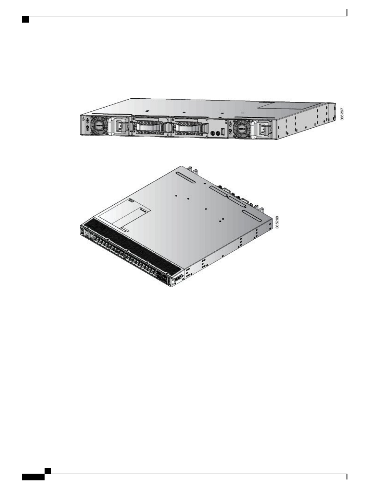
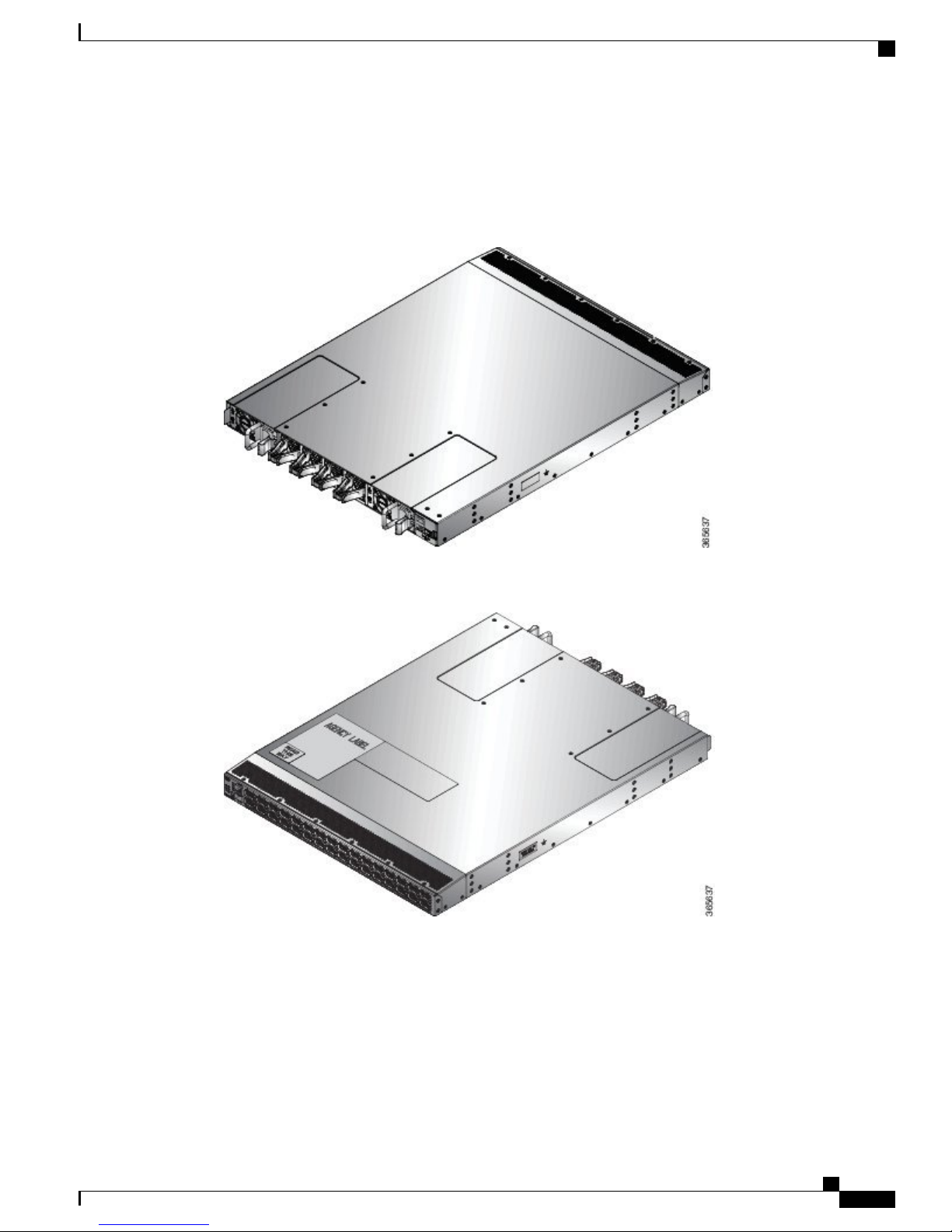
The Cisco NCS 5001 router is a small form factor dense GE/10GE aggregation systems. Powered by industry
leading routing operation system, IOS-XR, the system also offers rich functions such as third party application
hosting, machine-to-machine interface, telemetry and flexible package delivery.
Figure 1: Cisco NCS 5001 Router - Back (Fan Side) View
Figure 2: Cisco NCS 5001 Router - Front (Port Side) View
Ports
Cisco NCS 5001 router consists of the following ports:
40 x One GE/10GE SFP+ ports
•
16 x Regular 10G SFP+ Ports
◦
24 x DWDM and ZR Capable 10G SFP+ Ports (Purple in color)
◦
4 x 100G QSFP28 ports (Light Green in color)
•
Features
The Cisco NCS 5001 router has the following features:
Two 1+1 redundant, hot-swappable power supplies, which provide port side intake or exhaust for cooling
•
Two 1+1 redundant, hot-swappable fan modules, which provide port side intake or exhaust for cooling
•
Hardware Installation Guide for Cisco NCS 5000 Series Routers
2
Page 11
Overview
Cisco NCS 5001
A management and console interface are on the port (front) side of the router whereas the USB interface
•
on the fan (back) side of the router.
Power Supply
The Cisco NCS 5001 chassis has slots for two 1+1 redundant power supplies. Power supply options need to
be configured with the base chassis. A minimum of one power supply is required for normal operation. The
following table lists the power supplies that are configurable with the Cisco NCS 5001 router.
Table 2: Power Supplies for the Cisco NCS 5001 router
Power SupplyPart Number
Cisco NCS 5000 Power DC 930W Front to Back AirflowNC5K-PDC-930W-FR
Cisco NCS 5000 Power DC 930W Front to Back Airflow, spareNC5K-PDC-930W-FR=
Cisco NCS 5000 Power DC 930W Back to Front AirflowNC5K-PDC-930W-BK
Cisco NCS 5000 Power DC 930W Back to Front Airflow, spareNC5K-PDC-930W-BK=
Cisco NCS 5000 Series Router Power AC 650W Front to Back AirflowNC5K-PAC-650W-FR
NC5K-PAC-650W-FR=
Cisco NCS 5000 Series Router Power AC 650W Front to Back
Airflow, spare
Cisco NCS 5000 Series Router Power AC 650W Back to Front AirflowNC5K-PAC-650W-BK
NC5K-PAC-650W-BK=
Cisco NCS 5000 Series Router Power AC 650W Back to Front
Airflow, spare
Fan Modules
The Cisco NCS 5001 chassis has slots for two 1+1 redundant fan modules. The fan modules are hot-swappable.
Fan modules operate in an 1+1 redundancy mode. Fan options need to be configured with the base chassis.
The Cisco NCS 5001 system supports both forward and reverse airflow. The system can work with a single
fan failure. More than one fan failure leads to system shutdown. The following table lists the fan modules
that are configurable with the Cisco NCS 5001 router.
Table 3: Fan Modules for the Cisco NCS 5001 router
Fan ModulePart Number
Cisco NCS 5001 Router Fan Front to Back AirflowNCS-5001-FN-FR
Cisco NCS 5001 Router Fan Front to Back Airflow, spareNCS-5001-FN-FR=
Cisco NCS 5001 Router Fan Back to Front AirflowNCS-5001-FN-BK
Cisco NCS 5001 Router Fan Back to Front Airflow, spareNCS-5001-FN-BK =
Hardware Installation Guide for Cisco NCS 5000 Series Routers
3
Page 12
Cisco NCS 5002
Cisco NCS 5002
Cisco NCS 5002
The Cisco NCS 5002 router is also an extension to Cisco's routing platform portfolio enabling Service Providers
and MPLS enabled data center architectures to offer elastic networks with improved business agility and
simplified operations to deliver high-bandwidth mobile, video, and cloud services.
It can also operate as an extension shelf of Cisco ASR 9000 Series Aggregation Services Routers using
Network Virtualization (nV) technology, consolidating multiple layers in the network and dramatically reducing
operational costs.
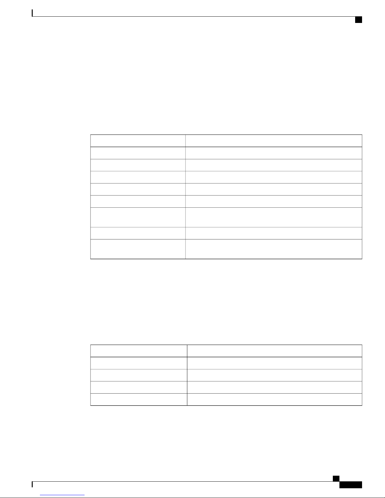
The Cisco NCS 5002 router is a small form factor dense GE/10GE aggregation systems in 2RU form factor.
Powered by industry leading routing operation system, IOS-XR, the system also offers rich functions such as
third party application hosting, machine-to-machine interface, telemetry and flexible package delivery.
Figure 3: Cisco NCS 5002 - Back (Fan Side) View
Overview
Figure 4: Cisco NCS 5002 - Front (Port Side) View
Ports
Cisco NCS 5002 router consists of the following ports:
Hardware Installation Guide for Cisco NCS 5000 Series Routers
4
Page 13
Overview
Cisco NCS 5002
80 x One GE/10GE SFP+ ports
•
40 x Regular 10G SFP+ Ports, on baseboard
◦
40 x DWDM and ZR Capable 10G SFP+ Ports, on mezzanine (Cisco Metallic Grey in color)
◦
4 x 100G QSFP28 ports (Light Green in color)
•
Features
The Cisco NCS 5002 router has the following features:
Two 1+1 redundant, hot-swappable power supplies, which provide port side intake or exhaust for cooling
•
Two 1+1 redundant, hot-swappable fan modules, which provide port side intake or exhaust for cooling
•
A management, console, and the USB interface on the port (front) side of the router
•
Power Supply
The Cisco NCS 5002 chassis has slots for two 1+1 redundant power supplies. Power supply options need to
be configured with the base chassis. A minimum of one power supply is required for normal operation. The
following table lists the power supplies that are configurable with the Cisco NCS 5002 router.
Table 4: Power Supplies for the Cisco NCS 5002 router
Power SupplyPart Number
Cisco NCS 5000 Power DC 930W Front to Back AirflowNC5K-PDC-930W-FR
Cisco NCS 5000 Power DC 930W Front to Back Airflow, spareNC5K-PDC-930W-FR=
Cisco NCS 5000 Power DC 930W Back to Front AirflowNC5K-PDC-930W-BK
Cisco NCS 5000 Power DC 930W Back to Front Airflow, spareNC5K-PDC-930W-BK=
NC5K-PAC-650W-FR
Cisco NCS 5000 Series Router Power AC 650W Front to Back
Airflow
NC5K-PAC-650W-FR=
Cisco NCS 5000 Series Router Power AC 650W Front to Back
Airflow, spare
NC5K-PAC-650W-BK
Cisco NCS 5000 Series Router Power AC 650W Back to Front
Airflow
NC5K-PAC-650W-BK=
Cisco NCS 5000 Series Router Power AC 650W Back to Front
Airflow, spare
Fan Modules
The Cisco NCS 5002 chassis has slots for two 1+1 redundant fan modules. The fan modules are hot-swappable.
Fan modules operate in an 1+1 redundancy mode. Fan options need to be configured with the base chassis.
The Cisco NCS 5002 system supports both forward and reverse airflow. The system can work with a single
fan failure. More than one fan failure leads to system shutdown. The following table lists the fan modules
that are configurable with the Cisco NCS 5002 router.
Hardware Installation Guide for Cisco NCS 5000 Series Routers
5
Page 14
Cisco NCS 5011
Overview
Table 5: Fan Modules for the Cisco NCS 5002 router
Fan ModulePart Number
NCS-5002-FN-FR
NCS-5002-FN-FR=
NCS-5002-FN-BK
NCS-5002-FN-BK=
Cisco NCS 5011
Cisco NCS 5011
The Cisco NCS 5011 router is also an extension to Cisco's routing platform portfolio enabling Service Providers
and MPLS enabled data center architectures to offer elastic networks with improved business agility and
simplified operations to deliver high-bandwidth mobile, video, and cloud services.
Cisco NCS 5002 Router Fan Front
to Back Airflow
Cisco NCS 5002 Router Fan Front
to Back Airflow, spare
Cisco NCS 5002 Router Fan Back
to Front Airflow
Cisco NCS 5002 Router Fan Back
to Front Airflow, spare
Hardware Installation Guide for Cisco NCS 5000 Series Routers
6
Page 15
Overview
Cisco NCS 5011
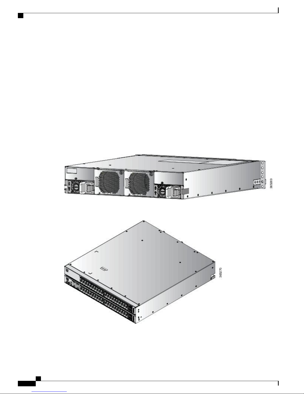
The Cisco NCS 5011 router is a small form factor dense GE/10GE aggregation systems in 1RU form factor.
Powered by industry leading routing operation system, IOS-XR, the system also offers rich functions such as
third party application hosting, machine-to-machine interface, telemetry and flexible package delivery.
Figure 5: Cisco NCS 5011 - Back (Fan Side) View
Figure 6: Cisco NCS 5011 - Front (Port Side) View
Ports
Cisco NCS 5011 router consists of the following ports:
2 x 10GE SFP + ports
•
32 x 100G QSFP28-100 ports
•
Hardware Installation Guide for Cisco NCS 5000 Series Routers
7
Page 16
Cisco NCS 5011
Overview
Features
The Cisco NCS 5011 router has the following features:
Two 1+1 redundant, hot-swappable power supplies, which provide port side intake or exhaust for cooling
•
Four 3+1 redundant, hot-swappable fan modules, which provide port side intake or exhaust for cooling
•
A management, console, and the USB interface on fan side of the router
•
Power Supply
The Cisco NCS 5011 chassis has slots for two 1+1 redundant power supplies. Power supply options need to
be configured with the base chassis. A minimum of one power supply is required for normal operation. The
following table lists the power supplies that are configurable with the Cisco NCS 5011 router.
Table 6: Power Supplies for the Cisco NCS 5011 router
Power SupplyPart Number
Cisco NCS 5000 Power DC 930W Front to Back AirflowNC5K-PDC-930W-FR
Cisco NCS 5000 Power DC 930W Front to Back Airflow, spareNC5K-PDC-930W-FR=
Cisco NCS 5000 Power DC 930W Back to Front AirflowNC5K-PDC-930W-BK
Cisco NCS 5000 Power DC 930W Back to Front Airflow, spareNC5K-PDC-930W-BK=
NC5K-PAC-650W-FR
Cisco NCS 5000 Series Router Power AC 650W Front to Back
Airflow
NC5K-PAC-650W-FR=
Cisco NCS 5000 Series Router Power AC 650W Front to Back
Airflow, spare
NC5K-PAC-650W-BK
Cisco NCS 5000 Series Router Power AC 650W Back to Front
Airflow
NC5K-PAC-650W-BK=
Cisco NCS 5000 Series Router Power AC 650W Back to Front
Airflow, spare
Fan Modules
The Cisco NCS 5011 chassis has slots for four 3+1 redundant fan modules. The fan modules are hot-swappable.
Fan options need to be configured with the base chassis. The Cisco NCS 5011 system supports both forward
and reverse airflow. The system can work with a single fan failure. More than one fan failure leads to system
shutdown. The following table lists the fan modules that are configurable with the Cisco NCS 5011 router.
Table 7: Fan Modules for the Cisco NCS 5011 router
NCS-5011-FN-FR
NCS-5011-FN-FR=
Hardware Installation Guide for Cisco NCS 5000 Series Routers
8
Fan ModulePart Number
Cisco NCS 5011 Router Fan Front
to Back Airflow
Cisco NCS 5011 Router Fan Front
to Back Airflow, spare
Page 17

Overview
Cisco NCS 5011
Fan ModulePart Number
NCS-5011-FN-BK
NCS-5011-FN-BK=
Cisco NCS 5011 Router Fan Back
to Front Airflow
Cisco NCS 5011 Router Fan Back
to Front Airflow, spare
Hardware Installation Guide for Cisco NCS 5000 Series Routers
9
Page 18

Cisco NCS 5011
Overview
Hardware Installation Guide for Cisco NCS 5000 Series Routers
10
Page 19

Safety Guidelines
This chapter lists and describes all the safety guidelines for Cisco NCS 5000 Series routers. Read these safety
guidelines before installing Cisco NCS 5000 routers.
Cisco NCS 5000 Safety Guidelines, page 11
•
Cisco NCS 5000 Safety Guidelines
CHAPTER 2
Note
Note
Note
Note
Caution
When handling router components, wear an ESD strap and handle modules by their handles and carrier
edges only. An ESD socket is provided on the chassis. For the ESD socket to be effective, the chassis
must be grounded through the power cable, the chassis ground, or the metal-to-metal contact with a
grounded rack.
Caution
If the rack is on wheels, ensure that the brakes are engaged or that the rack is otherwise stabilized.
Caution
To prevent loss of input power, ensure the total maximum loads on the circuits supplying power to the
router are within the current ratings for the wiring and breakers.
Caution
To prevent loss of input power, ensure the total maximum loads on the circuits supplying power to the
router are within the current ratings for the wiring and breakers.
Hardware Installation Guide for Cisco NCS 5000 Series Routers
11
Page 20

Cisco NCS 5000 Safety Guidelines
Safety Guidelines
Note
Warning
When installing or replacing the unit, the ground connection must always be made first and disconnected
last.
Hardware Installation Guide for Cisco NCS 5000 Series Routers
12
Page 21

CHAPTER 3
Prepare to Install Cisco NCS 5000
This chapter describes how to prepare the Cisco NCS 5000 series router for installation. This chapter includes
the following topics:
Installation Options with Racks and Cabinets, page 13
•
Airflow Direction, page 13
•
Chassis Weight, page 13
•
Required Equipment, page 14
•
Unpack and Inspect the New Router, page 14
•
Installation Options with Racks and Cabinets
The Cisco NCS 5000 series routers can be installed in the following types of racks using a rack-mount kit
shipped with the router:
Open EIA rack
•
Perforated EIA cabinet
•
To enable you to easily mount your router in any qualifying rack, you can attach the rack-mount brackets
accommodate racks of different depths.
Airflow Direction
The airflow direction of the Cisco NCS 5000 series routers can be configured as front-to-back (port side
intake), or back-to-front (port side exhaust). This is dependent on the type of fan modules and power supplies
configured with the chassis. It is not possible to mix airflow directions. In other words, all fan modules and
power supplies must either be configured to the same front-to-back, or back-to-front airflow directions.
Chassis Weight
When lifting the router chassis, follow these guidelines.:
Hardware Installation Guide for Cisco NCS 5000 Series Routers
13
Page 22

Required Equipment
Disconnect all power and external cables before lifting the router.
•
Ensure that two people lift the router. The Cisco NCS 5001 router with two power supplies, weighs 22
•
lb, and the Cisco NCS 5002 with two power supplies, weighs 46 lbs. The Cisco NCS 5011 with two
power supplies, weighs 22.2 lbs. Ensure that your footing is solid and the weight of the router is evenly
distributed between your feet.
Lift the router slowly, keeping your back straight. Lift with your legs, not with your back. Bend at the
•
knees, not at the waist.
Required Equipment
Before beginning the installation, ensure that you have the following items available:
Four 12-24 or 10-32 screws for attaching slider rails to the rack
•
Number 1 and number 2 Phillips screwdrivers with torque capability
•
3/16-inch flat-blade screwdriver
•
Prepare to Install Cisco NCS 5000
Tape measure and level
•
ESD wrist strap or other grounding device
•
Antistatic mat or antistatic foam
•
Also, the following additional items (not found in the accessory kit) are required to ground the chassis:
Grounding cable (6 AWG recommended), sized according to local and national installation requirements;
•
the required length depends on the proximity of the router to proper grounding facilities
Crimping tool, large enough to accommodate the girth of the lug
•
Wire-stripping tool
•
Unpack and Inspect the New Router
Before you install a new chassis, you need to unpack and inspect it to be sure that you have all the items that
you ordered and verify that the router was not damaged during shipment.
Caution
When handling router components, wear an ESD strap and handle modules by their handles and carrier
edges only. An ESD socket is provided on the chassis. For the ESD socket to be effective, the chassis
must be grounded through the power cable, the chassis ground, or the metal-to-metal contact with a
grounded rack.
Do not discard the shipping container when you unpack the router. Flatten the shipping cartons and store
Tip
them with the pallet used for the system. If you need to move or ship the system in the future, you will
need these containers.
Hardware Installation Guide for Cisco NCS 5000 Series Routers
14
Page 23

Prepare to Install Cisco NCS 5000
Unpack and Inspect the New Router
Note
Step 1
Step 2
Step 3
The router is thoroughly inspected before shipment. If any damage occurred during transportation or any
items are missing, contact your customer service representative immediately.
To inspect the shipment, follow these steps:
Procedure
Compare the shipment to the equipment list provided by your customer service representative and verify that
you have received all items ordered (optional items as well), including the following:
Grounding lug kit
•
Rack mount kit
•
ESD wrist strap
•
Cables with connectors
•
Filters (According to air flow direction)
•
Any optional items ordered
•
Check the contents of each box for damage.
If you notice any discrepancies or damage, send the following information to your customer service
representative by email:
Invoice number of the shipper (see the packing slip)
•
Model and serial number of the missing or damaged unit
•
Description of the problem and how it affects the installation
•
Photos of the damage to external packaging, internal packaging, and product
•
Effect of damage on the installation
•
Hardware Installation Guide for Cisco NCS 5000 Series Routers
15
Page 24

Unpack and Inspect the New Router
Prepare to Install Cisco NCS 5000
Hardware Installation Guide for Cisco NCS 5000 Series Routers
16
Page 25

Installing the NCS 5000 Router
This chapter describes how to install the Cisco NCS 5000 Series routers. This chapter includes the following
sections:
Installation Guidelines, page 17
•
Installing Cisco NCS 5000, page 18
•
Grounding Cisco NCS 5000, page 27
•
Starting Cisco NCS 5000, page 30
•
Installation Guidelines
When installing the Cisco NCS 5000 routers, follow these guidelines:
Ensure that there is adequate space around the router to allow for servicing the router and for adequate
•
airflow Technical Specifications, on page 47,lists the service and airflow requirements.
CHAPTER 4
Ensure that the air-conditioning meets the heat dissipation requirements listed in Technical Specifications,
•
on page 47
Ensure that the cabinet or rack meets the requirements listed in Cabinet and Rack Installation , on page
•
45
Note
Ensure that the chassis can be adequately grounded. If the router is not mounted in a grounded rack, we
•
recommend connecting both the system ground on the chassis and the power supply ground directly to
an earth ground.
Ensure that the site power meets the power requirements listed in Technical Specifications, on page
•
47. If available, you can use an uninterruptible power supply (UPS) to protect against power failures.
Ensure that circuits are sized according to local and national codes. For North America, the power supply
•
requires a 15-A or 20-A circuit.
Jumper power cords are available for use in a cabinet. See the Jumper Power Cord, on
page 57 section.
Hardware Installation Guide for Cisco NCS 5000 Series Routers
17
Page 26

Installing Cisco NCS 5000
Installing the NCS 5000 Router
Note
Caution
To prevent loss of input power, ensure the total maximum loads on the circuits supplying power to the
router are within the current ratings for the wiring and breakers.
Installing Cisco NCS 5000
The following sections describe how to install the Cisco NCS 5000 Series routers.
Installing Cisco NCS 5001
This section describes how to use the rack-mount kit provided with the router to install the Cisco NCS 5001
router into a cabinet or rack that meets the requirements described in Cabinet and Rack Installation , on page
45.
Note
Warning
If the rack is on wheels, ensure that the brakes are engaged or that the rack is otherwise stabilized.
The following table lists the items contained in the rack-mount kit provided with the Cisco NCS 5001 router.
Table 8: Cisco NCS 5001 Router Rack-Mount Kit
Step 1
Part DescriptionQuantity
Rack-mount brackets4
M4 x 0.7 x 7-mm Phillips flat-head screws16
Rack-mount guides4
Slider rails2
Procedure
Install the front rack-mount brackets on the chassis as follows:
a) Position a front rack-mount bracket on the side of the chassis with its four holes aligned to four of the six
screw holes on the front side of the chassis, and then use four M4 screws to attach the bracket to the chassis.
Note
You can align any four of the holes in the front rack-mount bracket to four of the six screw holes
in the chassis. The holes that you use depend on the requirements of your rack.
Hardware Installation Guide for Cisco NCS 5000 Series Routers
18
Page 27

Installing the NCS 5000 Router
b) Repeat Step 1a with the other front rack-mount bracket on the other side of the router.
Installing Cisco NCS 5001
Figure 7: Rack-mount brackets at the front on Cisco NCS 5001
Step 2
Install the rear rack-mount guides on the chassis as follows:
a) Position a rear rack-mount bracket on the side of the chassis with its four holes aligned to four of the six
screw holes on the side of the chassis, and then use four M4 screws to attach the bracket to the chassis.
Hardware Installation Guide for Cisco NCS 5000 Series Routers
19
Page 28

Installing Cisco NCS 5001
b) Repeat Step 2a with the other rear rack-mount bracket on the other side of the router.
Installing the NCS 5000 Router
Figure 8: Rack-mount brackets at the rear side on Cisco NCS 5001
Step 3
Step 4
Install the slider rails to the rack as follows:
a) Position the slider rails at the desired levels on the back side of the rack and use two 12-24 screws or two
10-32 screws, depending on the rack thread type, to attach the rails to the rack.
Note
For racks with square holes, you might need to position a 12-24 cage nut behind each mounting
hole in a slider rail before using a 12-24 screw.
b) Repeat with the other slider rail on the other side of the rack.
c) Use the tape measure and level to verify that the rails are at the same height and horizontal.
Insert the router into the rack and attach it as follows:
a) Holding the router with both hands, position the back of the router between the front posts of the rack.
b) Align the two rear rack-mount guides on either side of the router with the slider rails installed in the rack.
Slide the rack-mount guides onto the slider rails, and then gently slide the router all the way into the rack.
Note
If the router does not slide easily, try realigning the rack-mount guides on the slider
rails.
c) Holding the chassis level, insert two screws (12-24 or 10-32, depending on the rack type) through the cage
nuts and the holes in one of the front rack-mount brackets and into the threaded holes in the rack-mounting
rail.
d) Repeat for the other front rack-mount bracket on the other side of the router.
Hardware Installation Guide for Cisco NCS 5000 Series Routers
20
Page 29

Installing the NCS 5000 Router
Installing Cisco NCS 5002
This section describes how to use the rack-mount kit provided with the router to install the Cisco NCS 5002
router into a cabinet or rack that meets the requirements described in Cabinet and Rack Installation , on page
45.
Installing Cisco NCS 5002
Note
Step 1
Caution
If the rack is on wheels, ensure that the brakes are engaged or that the rack is otherwise stabilized.
The following table lists the items contained in the rack-mount kit provided with the Cisco NCS 5002 router.
Table 9: Cisco NCS 5002 Router Rack-Mount Kit
Part DescriptionQuantity
Rack-mount brackets4
M4 x 0.7 x 7-mm Phillips flat-head screws16
Rack-mount guides4
Slider rails2
Procedure
Install the front rack-mount brackets on the router as follows:
a) Position a front rack-mount bracket on the side of the router with its two holes aligned to two holes on the
front side of the router, and then use two M4 screws to attach the bracket to the router.
Hardware Installation Guide for Cisco NCS 5000 Series Routers
21
Page 30

Installing Cisco NCS 5002
b) Repeat Step 1a with the other front rack-mount bracket on the other side of the router.
Installing the NCS 5000 Router
Figure 9: Rack-Mount Brackets on the Front Side on Cisco NCS 5002
Step 2
2 - Screws1 - Rack mount bracket
Install the rear rack-mount guides on the rack as follows:
a) Assemble the rack mount and slider using 5 screws (12-24 screws or 10-32 screws depending on the rack
type) in front and 2 screws (12-24 screws or 10-32 screws depending on the rack type) on the back.
Hardware Installation Guide for Cisco NCS 5000 Series Routers
22
Page 31

Installing the NCS 5000 Router
b) Repeat Step 2a for the other side of the router.
Installing Cisco NCS 5002
Figure 10: Assembling Rack Mount and Slider
Step 3
2 - Rack mount1 - Slider
3 - Screws
Install the slider rails to the rack as follows:
Hardware Installation Guide for Cisco NCS 5000 Series Routers
23
Page 32

Installing Cisco NCS 5002
a) Position the router with the front rack mounts aligned at the location shown in the following image and
Installing the NCS 5000 Router
assemble on rack using one screw on either side (12-24 screws or 10-32 screws depending on the rack
type.
Figure 11: Slide the Cisco NCS 5002 Router
Note
For racks with square holes, you might need to position a 12-24 cage nut behind each mounting
hole in a slider rail before using a 12-24 screw.
b) Repeat with the other slider rail on the other side of the rack.
c) Use the tape measure and level to verify that the rails are at the same height and horizontal.
Step 4
Insert the router into the rack and attach it as follows:
a) Holding the router with both hands, position the back of the router between the front posts of the rack.
b) Align the two rear rack-mount guides on either side of the router with the slider rails installed in the rack.
Slide the rack-mount guides onto the slider rails, and then gently slide the router all the way into the rack.
Note
If the router does not slide easily, try realigning the rack-mount guides on the slider
rails.
c) Holding the router level, insert two screws (12-24 or 10-32, depending on the rack type) through the cage
nuts and the holes in one of the front rack-mount brackets and into the threaded holes in the rack-mounting
rail.
d) Repeat for the other front rack-mount bracket on the other side of the router.
Hardware Installation Guide for Cisco NCS 5000 Series Routers
24
Page 33

Installing the NCS 5000 Router
Installing Cisco NCS 5011
This section describes how to use the rack-mount kit provided with the router to install the Cisco NCS 5011
router into a cabinet or rack that meets the requirements described in Cabinet and Rack Installation , on page
45.
Installing Cisco NCS 5011
Note
Step 1
Caution
If the rack is on wheels, ensure that the brakes are engaged or that the rack is otherwise stabilized.
The following table lists the items contained in the rack-mount kit provided with the Cisco NCS 5011 router.
Table 10: Cisco NCS 5011 Router Rack-Mount Kit
Part DescriptionQuantity
Rack-mount brackets4
M4 x 0.7 x 7-mm Phillips flat-head screws16
Rack-mount guides4
Slider rails2
Procedure
Install the front rack-mount brackets on the router as follows:
a) Determine which end of the chassis is to be located in the cold aisle as follows:
If the switch has port-side intake modules, position the module so that its ports will be in the cold
•
aisle.
If the switch has port-side exhaust modules, position the module so that its fan and power supply
•
modules will be in the cold aisle.
b) Position a front rack-mount bracket so that four of its screw holes are aligned to the screw holes on the
side of the router, and then use four M4 screws to attach the bracket to the router.
Note
You can align any four of the holes in the front rack-mount bracket to four of the six screw holes
in the chassis. The holes that you use depend on the requirements of your rack.
Hardware Installation Guide for Cisco NCS 5000 Series Routers
25
Page 34

Installing Cisco NCS 5011
c) Repeat Step 1a with the other front rack-mount bracket on the other side of the router.
Installing the NCS 5000 Router
Figure 12: Rack-Mount Brackets on the Front Side on Cisco NCS 5011
Step 2
Install the rear rack-mount brackets on the rack as follows:
a) Align the two screw holes on a rear rack-mount bracket to the middle two screw holes in the remaining
six screw holes on a side of the chassis, and use two M4 screws to attach the bracket to the router.
b) Repeat Step 2a for the other side of the router.
Figure 13: Rack-mount brackets at the rear side on Cisco NCS 5011
Hardware Installation Guide for Cisco NCS 5000 Series Routers
26
Page 35

Installing the NCS 5000 Router
Grounding Cisco NCS 5000
Step 3
Step 4
Install the slider rails to the rack as follows:
a) Position the router with the front rack mounts aligned at the location shown in the following image and
assemble on rack using one screw on either side (12-24 screws or 10-32 screws depending on the rack
type.
b) Repeat with the other slider rail on the other side of the rack.
c) Use the tape measure and level to verify that the rails are at the same height and horizontal.
Insert the router into the rack and attach it as follows:
a) Holding the router with both hands, position the back of the router between the front posts of the rack.
b) Align the two rear rack-mount guides on either side of the router with the slider rails installed in the rack.
Slide the rack-mount guides onto the slider rails, and then gently slide the router all the way into the rack.
Note
c) Holding the router level, insert two screws (12-24 or 10-32, depending on the rack type) through the cage
nuts and the holes in one of the front rack-mount brackets and into the threaded holes in the rack-mounting
rail.
If the router does not slide easily, try realigning the rack-mount guides on the slider
rails.
Grounding Cisco NCS 5000
This section describes how to ground the Cisco NCS 5000 series routers.
Hardware Installation Guide for Cisco NCS 5000 Series Routers
27
Page 36

Grounding Cisco NCS 5000
Procedure
Installing the NCS 5000 Router
Step 1
On Cisco NCS 5001 and NCS 5011 remove the label on the rear side (fan side) of the router to expose the
ground mounting holes (as shown in the figure). On Cisco NCS 5002, remove the label on the right side of
the front side (port side) of the router to expose the ground mounting holes (as shown in the figure).
Figure 14: Grounding the Cisco NCS 5001 Router
3 - Label
Hardware Installation Guide for Cisco NCS 5000 Series Routers
28
2 - Ground Lug bracket1 - Ground Lug
Page 37

Installing the NCS 5000 Router
Figure 15: Grounding the Cisco NCS 5002 Router
Grounding Cisco NCS 5000
Figure 16: Grounding the Cisco NCS 5011 Router
2 - Label1 - Ground Lug
2 - Ground Lug bracket1 - Ground Lug
Hardware Installation Guide for Cisco NCS 5000 Series Routers
29
Page 38

Starting Cisco NCS 5000
3 - Label
Installing the NCS 5000 Router
Step 2
Step 3
Step 4
Install the ground lug bracket to the mounting holes with two flat head M4 X 7mm screws.
Install ground lug to the ground lug bracket with two pan head M4 screws.
Using a wire-stripping tool, remove the covering from one end of the grounding cable and insert the stripped
end of the grounding cable to the open end of the grounding lug.
Step 5
Prepare the other end of the ground cable and connect it to an appropriate grounding point in your site to
ensure adequate earth ground.
Starting Cisco NCS 5000
This section provides instructions for powering up the Cisco NCS 5000 series routers and verifying their
component installation.
Do not connect the Ethernet port to the LAN until the initial router configuration has been performed.Note
Note
Warning
When installing or replacing the unit, the ground connection must always be made first and disconnected
last.
Step 1
To power up the router and verify hardware operation, follow these steps:
Procedure
Verify that the power supply and the fan modules are installed.
Note
Depending on the outlet receptacle on your power distribution unit, you may need the optional jumper
power cord to connect the router to your outlet receptacle. See the Jumper Power Cord, on page 57
section.
Hardware Installation Guide for Cisco NCS 5000 Series Routers
30
Page 39

Installing the NCS 5000 Router
Starting Cisco NCS 5000
Step 2
Step 3
Step 4
Step 5
Step 6
Step 7
Step 8
Ensure that the router is adequately grounded as described in the Grounding Cisco NCS 5000, on page 27,
and that the power cables are connected to outlets that have the required AC power voltages (see Power
Specifications, on page 49)
For the router, insert each end of the power clip (from the accessory kit) into holes on tabs located on either
side of the power connectors.
Connect each power cable to the power connectors on the router and an AC power source. Press the power
cable into the power clip to ensure that the power cable stays connected to the router when bumped. The router
should power on as soon as you connect the power cable.
Check if the fans are operational; they should begin operating when the power cable is plugged in.
After the router boots up, verify that the power supply Status LED is green. After initialization, the system
status LED is green, indicating that all router environmental monitors are reporting that the system is operational.
If this LED is orange or red, then one or more environmental monitor is reporting a problem.
The Link LEDs for the Ethernet connector should not be ON unless the cable is connected.Note
Try removing and reinstalling a component that is not operating correctly. If it still does not operate correctly,
contact your customer service representative for a replacement.
Note
If you purchased this product through a Cisco reseller, contact the reseller directly for technical
support. If you purchased this product directly from Cisco, contact Cisco Technical Support at this
URL: http://www.cisco.com/en/US/support/tsd_cisco_worldwide_contacts.html.
Verify that the system software has booted and the router has initialized without error messages.
If you cannot resolve an issue, contact your customer service representative.
Hardware Installation Guide for Cisco NCS 5000 Series Routers
31
Page 40

Starting Cisco NCS 5000
Installing the NCS 5000 Router
Hardware Installation Guide for Cisco NCS 5000 Series Routers
32
Page 41

Replacing NCS 5000 Router Components
This chapter describes how to replace modules in the Cisco NCS 5000 Series routers. This chapter includes
the following sections:
Replacing a Fan Module, page 33
•
Replacing an AC Power Supply, page 36
•
Replacing a DC Power Supply , page 38
•
Replacing the Air Filter, page 39
•
Replacing a Fan Module
The fan tray is designed to be removed and replaced while the system is operating without causing an electrical
hazard or damage to the system if the replacement is performed within five minutes. If you do not have the
appropriate replacement fan module, leave the original fan module in its slot to preserve the designed airflow
for the router until you have the replacement fan module.
CHAPTER 5
Note
Note
Warning
The fans might still be turning when you remove the fan assembly from the chassis. Keep fingers,
screwdrivers, and other objects away from the openings in the fan assembly's housing.
Only one fan tray can be removed and replaced each time without disrupting the system.
•
Once you remove the fan tray, it must be replaced within 5 minutes.
•
Replacing a 1 (RU) Fan Module
The fan tray is designed to be removed and replaced while the system is operating without causing an electrical
hazard or damage to the system if the replacement is performed within one minute. If you do not have the
Hardware Installation Guide for Cisco NCS 5000 Series Routers
33
Page 42

Replacing a 1 (RU) Fan Module
appropriate replacement fan tray, leave the original fan tray in its slot to preserve the designed airflow for the
switch until you have the replacement fan module.
Before You Begin
Verify that you have an ESD wrist strap or other device to prevent ESD damage for components that
•
you touch.
Verify that you have an antistatic surface or bag for placing the fan module that you remove from the
•
chassis.
Verify that the replacement fan module has the correct direction of airflow (it has the same coloring as
•
the other fan and power supply modules in the same chassis).
Procedure
Replacing NCS 5000 Router Components
Step 1
Remove the fan module that you are replacing as follows:
a) On the fan module that you are removing, press the two sides of the fan module handle next to where it
connects to the fan module and pull on the handles enough to unseat the module from its connectors.
Figure 17: Replacing Fan Tray on NCS 5001
b) Holding the handle, pull the module out of the chassis and set it on an antistatic surface or in a antistatic
bag.
Note
Warning
Do not touch the electrical connectors on the back side of the module and prevent anything else
from coming into contact with and damaging the connectors.
Step 2
Install the replacement fan module as follows:
a) Holding the fan module by its handle, align the back of the fan module (the side with the electrical
connectors) to the open fan slot in the chassis.
b) Slide the fan module into the slot until it clicks in place.
Hardware Installation Guide for Cisco NCS 5000 Series Routers
34
Page 43

Replacing NCS 5000 Router Components
Replacing a 2 (RU) Fan Module
Before You Begin
Verify that you have an ESD wrist strap or other device to prevent ESD damage for components that
•
you touch.
Verify that you have an antistatic surface or bag for placing the fan module that you remove from the
•
chassis.
Verify that the replacement fan module has the correct direction of airflow (it has the same coloring as
•
the other fan and power supply modules in the same chassis).
Procedure
Replacing a 2 (RU) Fan Module
Step 1
Remove the fan module that you are replacing as follows:
a) Loosen the captive screws on the fan module by turning them counterclockwise, using a flat-blade or
number 2 Phillips screwdriver if required.
Figure 18: Replacing Fan Module on NCS 5002
b) Grasp the captive screws of the fan module and pull it outward.
c) Pull the fan module clear of the chassis and set it on an antistatic surface or repack it in packing materials.
Step 2
Install the replacement fan module as follows:
a) Hold the fan module with the sheet metal flange holding the connector on the bottom.
b) Place the fan module into the front chassis cavity so it rests on the chassis, and then push the fan module
into the chassis as far as it can go until the captive screw makes contact with the chassis.
c) Tighten the captive screw.
Hardware Installation Guide for Cisco NCS 5000 Series Routers
35
Page 44

Replacing an AC Power Supply
d) Listen for the fans if the device is powered on. You should immediately hear them operating. If you do
not hear them, ensure that the fan module is inserted completely in the chassis and the faceplate is flush
with the outside surface of the chassis.
Replacing an AC Power Supply
You can replace an AC power supply during operations so long as there is another power supply installed and
operating during the replacement. The switch requires only one power supply for operations, so you can hot
swap the redundant power supply during operations. If there is only one power supply installed in the chassis,
you can replace it by installing the new power supply in the open power supply slot before removing the other
power supply.
Before You Begin
Verify that you have an ESD wrist strap or other device to prevent ESD damage for components that
•
you touch.
Replacing NCS 5000 Router Components
Step 1
Verify that you have an antistatic surface or bag for placing the power supply module that you remove
•
from the chassis.
Verify that the replacement power supply module has the correct direction of airflow (it has the same
•
coloring as the other fan and power supply modules in the same chassis). Otherwise the switch can
overheat and shut down.
If fan filters are used for port side exhaust, then filters must be removed before removing the power
•
supply.
Procedure
Remove the power supply as follows:
a) Pull the power cord out from the power receptacle on the power supply to be removed and verify that the
OK LED turns off.
Hardware Installation Guide for Cisco NCS 5000 Series Routers
36
Page 45

Replacing NCS 5000 Router Components
b) Remove the power supply from the chassis by pushing and holding its thumb latch to the left and pulling
the power supply part way out of the chassis.
Figure 19: Replacing Power Supply Module on NCS 5001
Replacing an AC Power Supply
Figure 20: Replacing Power Supply Module on NCS 5002
c) Place your other hand under the power supply to support it while you slide it out of the chassis. Either
place the power supply on an antistatic surface or pack it in its packing materials.
Step 2
Install the replacement power supply as follows:
a) Holding the replacement power supply with one hand underneath the module and the other hand holding
the handle, align the back end of the power supply (the end with the electrical connections) to the open
power supply slot and slide the power supply all the way into the slot until it clicks into place.
Hardware Installation Guide for Cisco NCS 5000 Series Routers
37
Page 46

Replacing a DC Power Supply
b) Test the installation by trying to pull the power supply out of the slot without using the release latch. If
the power supply does not move out of place, it is secured in the slot. If the power supply moves, press it
all the way into the slot until it clicks in place.
Replacing NCS 5000 Router Components
Step 3
Connect the new power supply to an AC power source as follows
a) Attach the power cable to the electrical outlet on the front of the power supply.
b) Connect the other end of the power cable to an AC power source.
c) Verify that the power supply is operational by checking that the power supply OK LED is green.
What to Do Next
Replace the filters after replacing the power supply.
Replacing a DC Power Supply
Note
Step 1
Step 2
Step 3
Step 4
Step 5
Step 6
Before you begin the wiring procedure, turn off the DC power source from your facility's circuit breaker
to avoid electric shock hazard.
Procedure
Turn off the DC power at its source to avoid electric shock hazard.
Remove the power cord from the power cord retainer.
Remove the power cord from the power connector.
Press the release latch at the right side of the power supply module inward and slide the power supply out.
Insert the new power supply into the power-supply slot, and gently push it into the slot.
Connect the power cord to the power supply and to an DC power outlet. Turn on the power at the power
source.
Figure 21: Connect Power Cord to DC Power Outlet
Hardware Installation Guide for Cisco NCS 5000 Series Routers
38
Page 47

Replacing NCS 5000 Router Components
Replacing the Air Filter
Step 7
Verify that the power supply OK LED is green.
Replacing the Air Filter
A replaceable air filter is located on the front of the chassis. How often the air filters should be replaced
depends on the facility environment. In a dirty environment, or when you start getting frequent temperature
alarms, you should always check the intake grills for debris, and then check the air filters to see if they need
to be replaced.
Note
Step 1
In general, we recommend that you inspect the air filter every three months and replace, if necessary,
every 6 months.
Procedure
Remove the air filter that you are replacing as follows:
a) Loosen the captive screws that secure the fan filter. The air filter attaches to the front of the chassis for
port side inlet, in three parts (Piece A, Piece B and piece C as shown in the figure below). Remove piece
C first, followed by piece B and then piece A.
Figure 22: Replacing port side inlet air filter
Mid Panel (Piece C)23x5 captive screws1
Bottom Panel (Piece B)44x4 captive screws3
Unit Faceplate6Top Panel (Piece A)5
Hardware Installation Guide for Cisco NCS 5000 Series Routers
39
Page 48

Replace Power Module Air Filter
b) Slide out each of the air filter panels from the slot, and carefully set it aside.
Replacing NCS 5000 Router Components
Step 2
Install the air filter panels to the faceplate as follows:
a) Attach the upper filter panel to the lower filter panel using four long captive screws.
b) Attach the mid filter panel installed to the upper and lower filter panels using three short captive screws.
Note
Screws to be tightened to 2.0 ± 0.5 in-lbs of
torque.
Replace Power Module Air Filter
Procedure
Step 1
Step 2
To remove a power module air filter, follow these steps:
a) Place the screwdriver under the edge of the air filter clip-on holder.
b) Gently pry the holder loose with the screwdriver; it should pop off easily.
c) Remove the air filter from the front of the power module and set it carefully aside.
To replace a power module air filter, follow these steps:
a) Place the air filter in position on the front of the power module.
b) Place the holder in position on the front of the power module over the air filter.
c) Press the holder firmly but gently until it snaps into place.
Hardware Installation Guide for Cisco NCS 5000 Series Routers
40
Page 49

Replacing NCS 5000 Router Components
d) Slide in the power supply panel and tighten it using one screw.
Figure 23: Replacing the power module air filter
Replace Power Module Air Filter
Hardware Installation Guide for Cisco NCS 5000 Series Routers
41
Page 50

Replace Power Module Air Filter
e) Gently snap in the fan filter into the clip-on holder.
Figure 24: Replacing the fan filter
Replacing NCS 5000 Router Components
Hardware Installation Guide for Cisco NCS 5000 Series Routers
42
Page 51

Accessory Kits
Accessory Kit Contents, page 43
•
Accessory Kit Contents
This appendix describes the contents of the accessory kits for the Cisco NCS 5000 Series routers.
Cisco NCS 5001 Router Accessory Kit
This section describes the accessory kit contents for the Cisco NCS 5001 router accessory kit
(NCS-5001-ACSR). The Cisco NCS 5001 router accessory kit includes the following items:
2 rack-mount guides
•
2 rack-mount brackets
•
APPENDIX A
2 rack-mount sliders
•
16 M4 x 0.7 x 6-mm Phillips flat-head screws
•
1 console cable with an RJ-45-RS-232 adapter and a DB9 adapter
•
1 ground lug kit
•
1 ESD wrist strap
•
Additional parts can be ordered from your customer service representative.Note
Cisco NCS 5002 Router Accessory Kit
This section describes the accessory kit contents for the Cisco NCS 5002 router accessory kit
(NCS-5002-ACSR). The Cisco NCS 5002 router accessory kit includes the following items:
2 rack-mount guides
•
Hardware Installation Guide for Cisco NCS 5000 Series Routers
43
Page 52

Cisco NCS 5011 Router Accessory Kit
2 rack-mount brackets
•
2 rack-mount sliders
•
16 M4 x 0.7 x 6-mm Phillips flat-head screws
•
1 console cable with an RJ-45-RS-232 adapter and a DB9 adapter
•
1 ground lug kit
•
1 ESD wrist strap
•
Additional parts can be ordered from your customer service representative.Note
Cisco NCS 5011 Router Accessory Kit
This section describes the accessory kit contents for the Cisco NCS 5011 router accessory kit
(NCS-5011-ACSR). The Cisco NCS 5011 router accessory kit includes the following items:
Accessory Kits
2 rack-mount guides
•
2 rack-mount brackets
•
2 rack-mount sliders
•
16 M4 x 0.7 x 6-mm Phillips flat-head screws
•
1 console cable with an RJ-45-RS-232 adapter and a DB9 adapter
•
1 ground lug kit
•
1 ESD wrist strap
•
Additional parts can be ordered from your customer service representative.Note
Hardware Installation Guide for Cisco NCS 5000 Series Routers
44
Page 53

Cabinet and Rack Installation
This appendix provides the requirements for cabinet and rack installation for the Cisco NCS 5000 router and
includes the following sections:
Cabinet and Rack Requirements, page 45
•
Cable Management Guidelines, page 46
•
Cabinet and Rack Requirements
This section provides the requirements for the following types of cabinets and racks, assuming an external
ambient air temperature range of 0° F to 104° F (0° C to 40° C):
Standard perforated cabinets
•
Standard open racks
•
APPENDIX B
Note
Note
If you are selecting an enclosed cabinet, we recommend one of the thermally validated types: standard
perforated or solid-walled with a fan tray.
Do not use racks that have obstructions (such as power strips), because the obstructions could impair
access to field-replaceable units (FRUs).
This section includes the following topics:
General Requirements for Cabins and Racks, on page 45
Requirements Specific to Perforated Cabinets, on page 46
General Requirements for Cabins and Racks
The cabinet or rack must be one of the following types:
Hardware Installation Guide for Cisco NCS 5000 Series Routers
45
Page 54

Requirements Specific to Perforated Cabinets
Standard 19-in. (48.3 cm) (four-post EIA cabinet or rack, with mounting rails that conform to English
•
universal hole spacing per section 1 of ANSI/EIA-310-D-1992. See the “Requirements Specific to
Perforated Cabinets, on page 46”.
The cabinet or rack must also meet the following requirements:
The minimum vertical rack space for the Cisco NCS 5000 router chassis must be one RU (rack units).
•
The width between the rack-mounting rails must be at least 19 inches if the rear of the router is not
•
attached to the rack. For four-post EIA racks, this is the distance between the two front rails.
For four-post EIA cabinets (perforated or solid-walled), the requirements are as follows:
•
The minimum spacing for the bend radius for fiber-optic cables should have the front-mounting
•
rails of the cabinet offset from the front door by a minimum of 3 inches (7.6 cm), and a minimum
of 5 inches (12.7 cm) if cable management brackets are installed on the front of the chassis.
The distance between the outside face of the front mounting rail and the outside face of the back
•
mounting rail should be 23.5 to 34.0 inches (59.7 to 86.4 cm) to allow for rear-bracket installation.
A minimum of 2.5 inches (6.4 cm) of clear space should exist between the side edge of the chassis
•
and the side wall of the cabinet. No sizeable flow obstructions should be immediately in the way
of chassis air intake or exhaust vents.
Cabinet and Rack Installation
Note
Optional jumper power cords are available for use in a cabinet. See the Jumper Power
Cord section on page C-8
Requirements Specific to Perforated Cabinets
A perforated cabinet is as a cabinet with perforated front and rear doors and solid side walls. In addition to
the requirements listed in the “General Requirements for Cabins and Racks, on page 45” , perforated cabinets
must meet the following requirements:
The front and rear doors must have at least a 60 percent open area perforation pattern, with at least 15
•
square inches (96.8 square cm) of open area per rack unit of door height.
The roof should be perforated with at least a 20 percent open area.
•
The cabinet floor should be open or perforated to enhance cooling.
•
Cisco provides an R-Series rack that conforms to these requirements.
Cable Management Guidelines
To help with cable management, you might want to allow additional space in the rack above and below the
chassis to make it easier to route as many as 56 fiber or copper cables through the rack.
Hardware Installation Guide for Cisco NCS 5000 Series Routers
46
Page 55

Technical Specifications
This appendix describes the technical specifications for the Cisco NCS 5001 and 5002 routers. This appendix
includes the following sections:
Router Specifications, page 47
•
Environment Specification, page 48
•
Power Specifications, page 49
•
Router Specifications
The following table lists the physical specifications for the Cisco NCS 5001 router.
Table 11: Physical Specifications for the Cisco NCS 5001 Router
APPENDIX C
SpecificationDescription
Dimensions (H x W x D)
two fan modules
The following table lists the physical specifications for the Cisco NCS 5002 router.
Table 12: Physical Specifications for the Cisco NCS 5002 Router
two fan modules
1.72 x 17.42 x 19.28 in. (4.4 cm x 44.3 cm x 48.97
cm)
22 lb (10 kg)Cisco NCS 5001 with two 650W power supplies, and
SpecificationDescription
3.5 x 17.42 x 19.28 in. (8.9 cm x 44.3 cm x 48.97 cm)Dimensions (H x W x D)
46 lb (20.9 kg)Cisco NCS 5002 with two 650W power supplies, and
Hardware Installation Guide for Cisco NCS 5000 Series Routers
47
Page 56

Environment Specification
Table 13: Physical Specifications for the Cisco NCS 5011 Router
four fan modules
Environment Specification
The following table lists the environmental specifications for the Cisco NCS 5001 Router.
Table 14: Environmental Specifications for the Cisco NCS 5001 Router
Technical Specifications
SpecificationDescription
1.72 x 17.3 x 22.5 in. (4.4 cm x 43.9 cm x 57.15 cm)Dimensions (H x W x D)
22.2 lb (10.6 kg)Cisco NCS 5011 with two 650W power supplies, and
Cisco NCS 5001 RouterProperty
32 to 104°F (0 to 40°C)Operating temperature
-40 to 158°F (-40 to 70°C)Nonoperating (storage) temperature
5 to 95% (non condensing)Humidity
0 to 10,000 ft (0 to 3000 m)Altitude
Table 15: Environmental Specifications for the Cisco NCS 5002 Router
Cisco NCS 5002 RouterProperty
32 to 104°F (0 to 40°C)Operating temperature
-40 to 158°F (-40 to 70°C)Nonoperating (storage) temperature
5 to 95% (non condensing)Humidity
0 to 10,000 ft (0 to 3000 m)Altitude
Table 16: Environmental Specifications for the Cisco NCS 5011 Router
Hardware Installation Guide for Cisco NCS 5000 Series Routers
48
Cisco NCS 5011 RouterProperty
32 to 104°F (0 to 40°C)Operating temperature
-40 to 158°F (-40 to 70°C)Nonoperating (storage) temperature
5 to 95% (non condensing)Humidity
Page 57

Technical Specifications
Cisco NCS 5011 RouterProperty
0 to 10,000 ft (0 to 3000 m)Altitude
Power Specifications
This section describes the power specifications for the Cisco NCS 5000 Series routers.
Specifications for the Cisco NCS 5001 Power Supply
The following table lists the Power supply specifications for the Cisco NCS 5001 Series routers.
Table 17: Specifications for the Cisco NCS 5001 AC Power Supply
SpecificationsAC Power Supply Properties
Power Specifications
357 WTypical operating power
650 WMaximum Power
110/220Input Voltage
47 Hz to 53 HzFrequency
94% (At 50% Load)Efficiency
YesRoHS Compliance
YesHot Swappable
YesPort side exhaust air flow power supply
YesPort side intake air flow power supply
Table 18: Specifications for the Cisco NCS 5001 DC Power Supply
SpecificationsDC Power Supply Properties
511 WTypical operating power
930 WMaximum Power
-48/-60Input Voltage
94% (At 50% Load)Efficiency
Hardware Installation Guide for Cisco NCS 5000 Series Routers
49
Page 58

Specifications for the Cisco NCS 5002 Power Supply
SpecificationsDC Power Supply Properties
YesRoHS Compliance
The minimum cable sizing required for DC power supply is 10 AWG.Note
Specifications for the Cisco NCS 5002 Power Supply
The following table lists the Power supply specifications for the Cisco NCS 5002 Series router.
Table 19: Specifications for the Cisco NCS 5002 AC Power Supply
SpecificationsAC Power Supply Properties
Technical Specifications
357 WTypical operating power
650 WMaximum Power
110/220Input Voltage
47 Hz to 53 HzFrequency
94% (At 50% Load)Efficiency
YesRoHS Compliance
YesHot Swappable
YesPort side exhaust air flow power supply
YesPort side intake air flow power supply
Table 20: Specifications for the Cisco NCS 5002 DC Power Supply
SpecificationsDC Power Supply Properties
511 WTypical operating power
Hardware Installation Guide for Cisco NCS 5000 Series Routers
50
930 WMaximum Power
-48/-60Input Voltage
94% (At 50% Load)Efficiency
Page 59

Technical Specifications
Specifications for the Cisco NCS 5011 Power Supply
SpecificationsDC Power Supply Properties
YesRoHS Compliance
The minimum cable sizing required for DC power supply is 10 AWG.Note
Specifications for the Cisco NCS 5011 Power Supply
The following table lists the Power supply specifications for the Cisco NCS 5011 Series router.
Table 21: Specifications for the Cisco NCS 5011 AC Power Supply
SpecificationsAC Power Supply Properties
357 WTypical operating power
650 WMaximum Power
110/220Input Voltage
47 Hz to 53 HzFrequency
94% (At 50% Load)Efficiency
YesRoHS Compliance
YesHot Swappable
YesPort side exhaust air flow power supply
YesPort side intake air flow power supply
Table 22: Specifications for the Cisco NCS 5011 DC Power Supply
SpecificationsDC Power Supply Properties
511 WTypical operating power
930 WMaximum Power
-48/-60Input Voltage
94% (At 50% Load)Efficiency
Hardware Installation Guide for Cisco NCS 5000 Series Routers
51
Page 60

Specifications for the Cisco NCS 5011 Power Supply
The minimum cable sizing required for DC power supply is 10 AWG.Note
Technical Specifications
SpecificationsDC Power Supply Properties
YesRoHS Compliance
Hardware Installation Guide for Cisco NCS 5000 Series Routers
52
Page 61

Cable and Port Specification
This appendix provides cable and port specifications for the Cisco NCS 5001 and 5002 Series routers.
Console Port, page 53
•
Supported Power Cords and Plugs, page 53
•
Jumper Power Cord, page 57
•
Console Port
The console port is an asynchronous RS-232 serial port with an RJ-45 connector.
Supported Power Cords and Plugs
APPENDIX D
Each power supply has a separate power cord. Standard power cords or jumper power cords are available for
connection to a power distribution unit that has IEC 60320 C19 outlet receptacles. The standard power cords
have an IEC C13 connector on the end that plugs into the router. The optional jumper power cords, for use
in cabinets, have an IEC C13 connector on the end that plugs into the router and an IEC C14 connector on
the end that plugs into an IEC C13 outlet receptacle.
Only the regular power cords or jumper power cords provided with the router are supported.Note
The following table lists the power cords for the Cisco NCS 5000 Series router and provides their lengths in
feet and meters.
Hardware Installation Guide for Cisco NCS 5000 Series Routers
53
Page 62

Supported Power Cords and Plugs
Table 23: Power Cords for the Cisco NCS 5000 Series Router
cord 250 VAC 10 A, IRAM
2073 plug Argentina
cord 250 VAC 10 A, 3112
plug, Australia
Cable and Port Specification
Power Cord Reference IllustrationLengthDescription
MetersFeet
2.58.2CAB-250V-10A-AR Power
2.58.2CAB-9K10A-AU Power
cord 250 VAC 10 A, GB
2009 plug China
cord, 250 VAC 10 A, M
2511 plug Europe
cord 250 VAC 16A, EL-208
plug South Africa, United
Arab Emirates, India
2.58.2CAB-250V-10A-CN Power
2.58.2CAB-9K10A-EU Power
2.58.2CAB250V-10A-ID Power
Hardware Installation Guide for Cisco NCS 5000 Series Routers
54
Page 63

Cable and Port Specification
cord 250 VAC 10 A, SI-32
plug Israel
250 VAC 10 A, CEI 23-16
plug Italy
Supported Power Cords and Plugs
Power Cord Reference IllustrationLengthDescription
MetersFeet
2.58.2CAB-250V-10A-IS Power
2.58.2CAB-9K10A-IT Power cord
cord 250 VAC 10 A, MP232
plug Switzerland
cord 250 VAC 10 A,
BS1363 plug (13 A fuse)
United Kingdom
cord 250 VAC 13 A, NEMA
L6-20 plug North America
2.58.2CAB-9K10A-SW Power
2.58.2CAB-9K10A-UK Power
2.06.6CAB-AC-250V/13A Power
Hardware Installation Guide for Cisco NCS 5000 Series Routers
55
Page 64

Supported Power Cords and Plugs
cord 250 VAC 10 A, NEMA
6-15 plug North America
cord 125 VAC 13 A, NEMA
5-15 plug North America
Cable and Port Specification
Power Cord Reference IllustrationLengthDescription
MetersFeet
2.58.2CAB-N5K6A-NA Power
2.58.2CAB-9K12A-NA Power
250 VAC 10 A, SS 10A plug
250 VAC 10 A, EL 208B
plug
Cabinet Jumper Power Cord
250 VAC 13 A, C13-C14
Connectors
2.58.2CAB-C13-CBN Power cord
2.58.2CAB-IND-10A Power cord
0.72.2CAB-C13-C14-JMPR
Hardware Installation Guide for Cisco NCS 5000 Series Routers
56
Page 65

Cable and Port Specification
Jumper Power Cord
The following figure shows the plug connector on the optional jumper power cord for the Cisco NCS 5001
and 5002 Series routers. This cable plugs into the power supply, and the receptacle of a power distribution
unit for a cabinet. This cable comes in 6- and 9-foot (2- and 3-meter) lengths.
Figure 25: CAB-C13-C14-JMPR, Jumper Power Cord
Jumper Power Cord
Hardware Installation Guide for Cisco NCS 5000 Series Routers
57
Page 66

Jumper Power Cord
Cable and Port Specification
Hardware Installation Guide for Cisco NCS 5000 Series Routers
58
Page 67

APPENDIX E
LEDs
This appendix describes the conditions indicated by the chassis and module LEDs on the Cisco NCS 5000
Series routers.
Chassis and Module LEDs for the Cisco NCS 5000 Series Routers, page 59
•
Chassis and Module LEDs for the Cisco NCS 5000 Series Routers
This section includes the following topics:
Chassis and Module LED Descriptions, on page 59
Conditions Indicated by the Power Supply LEDs, on page 60
Chassis and Module LED Descriptions
This table describes the chassis LEDs for the Cisco NCS 5000 Series routers.
StateStatusColorFunctionLocationIndicator
Front of ChassisPower LED
Power/Health
Hardware Installation Guide for Cisco NCS 5000 Series Routers
Solid OnGreenChassis
Off
System is On
and operating
normally.
Router is
powered off.
Fault Condition.OnAmber
59
Page 68

Conditions Indicated by the Power Supply LEDs
LEDs
StateStatusColorFunctionLocationIndicator
PSU Status
Indicators
Power
Supply(front)
Health(Multi-Color)
Conditions Indicated by the Power Supply LEDs
You can determine the power supply conditions by combining the LED states of the OK and FAIL LEDs .
OffGreenPSU
Solid On
Solid OnAmber
1 Hz blinking
Off
No AC power to
power supply.
power supply on
and OK.
Power supply
failures, over
voltage, over
current, over
temperature
AC present,
3.3VSB on, PSU
is off
Operating
normally .
Table 24: Power Supply LED Descriptions
AC Power Supply Condition
and fan failure.
These events include high temperature, high power, and slow fan.
For a DC power supply, it indicates that DC power is present.
OK
LED(Green)
FAILED
LED(Amber)
OffOffNo AC or DC power to all power supplies.
OnoffPower supply failure, including over voltage, over current, over temperature,
BlinkingOffPower supply warning events where the power supply continues to operate.
OffBlinkingAC present, 3.3 voltage standby (VSB) on, and the power supply unit is off.
OffOnPower supply on and OK.
Hardware Installation Guide for Cisco NCS 5000 Series Routers
60
Page 69

Overview
APPENDIX F
Troubleshooting Hardware Components
This appendix describes how to identify and resolve problems that might occur with the hardware components
of a Cisco NCS 5000 Series routers.
Overview, page 61
•
Router Hardware Best Practices, page 61
•
Power Supply Conditions, page 62
•
The key to success when troubleshooting the system hardware is to isolate the problem to a specific system
component. The first step is to compare what the system is doing to what it should be doing. Because a startup
problem can usually be attributed to a single component, it is more efficient to isolate the problem to a
subsystem rather than troubleshoot each separate component in the system.
Problems with the initial power up are often caused by a module that is not firmly connected to the backplane
or a power supply that has been disconnected from the power cord connector.
Overheating can also cause problems with the system, though typically only after the system has been operating
for an extended period of time. The most common cause of overheating is the failure of a fan module.
Router Hardware Best Practices
Use the recommendations in this section to ensure the proper installation, initialization, and operation of the
router.
This section includes the following topics:
Installation Best Practices, on page 62
•
Initialization Best Practice, on page 62
•
Power Supply Conditions, on page 62
•
Hardware Installation Guide for Cisco NCS 5000 Series Routers
61
Page 70

Installation Best Practices
Installation Best Practices
When installing the router, follow these best practices:
Plan your site configuration and prepare the site before installing the chassis.
•
Verify that you have the appropriate power supplies for your chassis configuration.
•
Install the chassis following the rack and airflow guidelines presented in this guide.
•
Verify that the chassis is adequately grounded.
•
Initialization Best Practice
When the initial system boot is complete, verify the following:
Power supplies are supplying power to the system.
•
Fan modules are operating normally.
•
Troubleshooting Hardware Components
The system software boots successfully.
•
Router Operation Best Practices
To ensure proper operation of your router, take the following actions:
Make a copy of the running configuration to CompactFlash for a safe backup.
•
Always enter the copy running-config startup-config CLI command after you modify the running
•
configuration and ensure that the system is operating properly.
Never use the init system CLI command unless you understand that you will lose the running and startup
•
configuration as well as the files stored on bootflash.
Keep backup copies of the running kickstart and the system images on CompactFlash.
•
Power Supply Conditions
The two LEDs on each power supply indicate the power status for each power supply. To determine the current
status for a power supply unit, note which LED is on, blinking, or off and refer the following table.
Table 25: Power Supply Condition
overvoltage, overcurrent,
overtemperature, and fan failure.
Hardware Installation Guide for Cisco NCS 5000 Series Routers
62
Fail LED StatusPower LED StatusPower Supply Condition
OffOffNo power to all power status.
OnOffPower supply failure, including
Page 71

Troubleshooting Hardware Components
where the power supply continues
to operate. These events include
high temperature, high power, and
slow fan.
(VSB) on, and the power supply
unit is off.
Power Supply Conditions
Fail LED StatusPower LED StatusPower Supply Condition
BlinkingOffPower supply warning events
OffBlinkingAC present, 3.3 voltage standby
OffOnPower supply on and OK.
Hardware Installation Guide for Cisco NCS 5000 Series Routers
63
Page 72

Power Supply Conditions
Troubleshooting Hardware Components
Hardware Installation Guide for Cisco NCS 5000 Series Routers
64
 Loading...