

Page 1

Cisco Network Convergence System
4000 Series Hardware Installation Guide
November 2015
Cisco Systems, Inc.
www.cisco.com
Cisco has more than 200 offices worldwide.
Addresses, phone numbers, and fax numbers
are listed on the Cisco website at
www.cisco.com/go/offices.
Text Part Number:
Page 2

THE SPECIFICATIONS AND INFORMATION REGARDING THE PRODUCTS IN THIS MANUAL ARE SUBJECT TO CHANGE WITHOUT NOTICE. ALL
STATEMENTS, INFORMATION, AND RECOMMENDATIONS IN THIS MANUAL ARE BELIEVED TO BE ACCURATE BUT ARE PRESENTED WITHOUT
WARRANTY OF ANY KIND, EXPRESS OR IMPLIED. USERS MUST TAKE FULL RESPONSIBILITY FOR THEIR APPLICATION OF ANY PRODUCTS.
THE SOFTWARE LICENSE AND LIMITED WARRANTY FOR THE ACCOMPANYING PRODUCT ARE SET FORTH IN THE INFORMATION PACKET THAT
SHIPPED WITH THE PRODUCT AND ARE INCORPORATED HEREIN BY THIS REFERENCE. IF YOU ARE UNABLE TO LOCATE THE SOFTWARE LICENSE
OR LIMITED WARRANTY, CONTACT YOUR CISCO REPRESENTATIVE FOR A COPY.
The following information is for FCC compliance of Class A devices: This equipment has been tested and found to comply with the limits for a Class A digital device, pursuant
to part 15 of the FCC rules. These limits are designed to provide reasonable protection against harmful interference when the equipment is operated in a commercial
environment. This equipment generates, uses, and can radiate radio-frequency energy and, if not installed and used in accordance with the instruction manual, may cause
harmful interference to radio communications. Operation of this equipment in a residential area is likely to cause harmful interference, in which case users will be required
to correct the interference at their own expense.
The following information is for FCC compliance of Class B devices: The equipment described in this manual generates and may radiate radio-frequency energy. If it is not
installed in accordance with Cisco’s installation instructions, it may cause interference with radio and television reception. This equipment has been tested and found to
comply with the limits for a Class B digital device in accordance with the specifications in part 15 of the FCC rules. These specifications are designed to provide reasonable
protection against such interference in a residential installation. However, there is no guarantee that interference will not occur in a particular installation.
Modifying the equipment without Cisco’s written authorization may result in the equipment no longer complying with FCC requirements for Class A or Class B digital
devices. In that event, your right to use the equipment may be limited by FCC regulations, and you may be required to correct any interference to radio or television
communications at your own expense.
You can determine whether your equipment is causing interference by turning it off. If the interference stops, it was probably caused by the Cisco equipment or one of its
peripheral devices. If the equipment causes interference to radio or television reception, try to correct the interference by using one or more of the following measures:
• Turn the television or radio antenna until the interference stops.
• Move the equipment to one side or the other of the television or radio.
• Move the equipment farther away from the television or radio.
• Plug the equipment into an outlet that is on a different circuit from the television or radio. (That is, make certain the equipment and the television or radio are on circuits
controlled by different circuit breakers or fuses.)
Modifications to this product not authorized by Cisco Systems, Inc. could void the FCC approval and negate your authority to operate the product.
The Cisco implementation of TCP header compression is an adaptation of a program developed by the University of California, Berkeley (UCB) as part of UCB’s public
domain version of the UNIX operating system. All rights reserved. Copyright © 1981, Regents of the University of California.
NOTWITHSTANDING ANY OTHER WARRANTY HEREIN, ALL DOCUMENT FILES AND SOFTWARE OF THESE SUPPLIERS ARE PROVIDED “AS IS” WITH
ALL FAULTS. CISCO AND THE ABOVE-NAMED SUPPLIERS DISCLAIM ALL WARRANTIES, EXPRESSED OR IMPLIED, INCLUDING, WITHOUT
LIMITATION, THOSE OF MERCHANTABILITY, FITNESS FOR A PARTICULAR PURPOSE AND NONINFRINGEMENT OR ARISING FROM A COURSE OF
DEALING, USAGE, OR TRADE PRACTICE.
IN NO EVENT SHALL CISCO OR ITS SUPPLIERS BE LIABLE FOR ANY INDIRECT, SPECIAL, CONSEQUENTIAL, OR INCIDENTAL DAMAGES, INCLUDING,
WITHOUT LIMITATION, LOST PROFITS OR LOSS OR DAMAGE TO DATA ARISING OUT OF THE USE OR INABILITY TO USE THIS MANUAL, EVEN IF CISCO
OR ITS SUPPLIERS HAVE BEEN ADVISED OF THE POSSIBILITY OF SUCH DAMAGES.
Cisco and the Cisco logo are trademarks or registered trademarks of Cisco and/or its affiliates in the U.S. and other countries. To view a list of Cisco trademarks, go to this
URL: www.cisco.com/go/trademarks. Third-party trademarks mentioned are the property of their respective owners. The use of the word partner does not imply a partnership
relationship between Cisco and any other company. (1110R)
Cisco Network Convergence System 4000 Series Routers Hardware Installation Guide
© 2015 Cisco Systems, Inc. All rights reserved.
Page 3

CONTENTS
Preface ix
Audience ix
Conventions ix
Related Documentation x
Obtaining Documentation and Submitting a Service Request x
CHAPTER
CHAPTER
CHAPTER
1 Installation Roadmap 1-1
2 Chassis Overview 2-1
About the Cisco NCS 4016 Chassis 2-1
Chassis Components 2-5
Chassis Slot Numbers 2-7
Card Slot Requirements 2-8
Chassis Cable Management 2-10
Safety Guidelines 2-10
Preventing Electrostatic Discharge 2-11
3 Site Planning Considerations 3-1
Basic Site and Installation Planning 3-1
Equipment Rack Considerations 3-2
Aisle Spacing and Maintenance Access Floor Plan 3-3
Front and Rear Clearances 3-4
Cable Management 3-4
Route Processor Cables 3-4
Interface Cables 3-5
CHAPTER
Noise Control 3-5
Cisco Installation Services 3-5
System Testing, Certification, and Warranties 3-5
4 Installing Power Components 4-1
Power Connection Guidelines 4-1
AC-Powered Chassis 4-2
Cisco Network Convergence System 4000 Series Hardware Installation Guide
iii
Page 4

Contents
DC-Powered Chassis 4-2
General Power and Grounding Requirements 4-5
DC Power Requirements 4-5
AC Power Requirements 4-6
NEBS Supplemental Unit Bonding and Grounding Guidelines 4-6
Installing the Chassis Ground Cable 4-8
Installing an AC or DC Power Tray 4-11
Installing Power Modules 4-12
Installing AC or DC Power Modules 4-13
Installing the DC Power Front Connection Adapter 4-15
Connecting Power to the Chassis 4-23
Connecting Power to an AC-Powered Chassis 4-23
Connecting Power to a DC-Powered Chassis 4-25
Disconnecting AC or DC Power 4-28
Disconnecting AC Power 4-28
Reconnecting AC Power 4-28
Disconnecting DC Power 4-29
Reconnecting DC Power 4-30
CHAPTER
Powering On the Chassis 4-30
5 Installing Route Processor Cards, Fabric Cards, and Line Cards 5-1
About Installing Cards and Associated Components 5-1
Preventing Electrostatic Discharge 5-1
Guidelines for Installing and Removing a Card 5-2
Installing and Removing a Filler Card 5-3
Installing a Filler Card 5-3
Removing a Filler Card 5-5
About RP Cards 5-5
Installing an RP Card 5-5
Installing an RP Card 5-6
Verifying and Troubleshooting the Installation of an RP Card 5-9
Troubleshooting the RP Card 5-10
About Fabric Cards 5-11
Installing a Fabric Card 5-11
Installing a Fabric Card 5-11
Verifying the Installation of a Fabric Card 5-15
iv
About Line Cards 5-16
2-Port 100Gbps and 10-Port 10Gbps OTN and Packet Line Card 5-16
Cisco Network Convergence System 4000 Series Hardware Installation Guide
Page 5

24-Port Low-Rate OTN Line Card 5-18
20-Port 10GE OTN Line Card 5-20
2-Port 100GE OTN Line Card 5-22
2-Port 100GE DWDM Line Card 5-24
Pluggable Optics Support 5-26
Installing a Line Card 5-27
Installing a Line Card 5-27
Verifying the Installation of a Line Card 5-30
Connecting Line Card Network Interface Cables 5-31
Connecting Cables to the RP 5-34
Connecting to the Console Port 5-35
Connecting to the Ethernet Management Ports 5-35
Contents
CHAPTER
6 Removing and Replacing Chassis Components 6-1
Removing a Line Card 6-1
Removing an RP Card 6-3
Removing a Fabric Card 6-5
Removing the Power Components 6-7
Removing AC Input Power Cords 6-8
Removing DC Input Power Cables 6-8
Removing a Power Module Slot Cover 6-9
Removing an AC or DC Power Module 6-10
Removing an AC or DC Power Tray 6-11
Removing the Chassis Ground Cable 6-12
Replacing the Air Filter 6-13
Replacing the Front Door 6-17
Replacing the Fan Tray 6-23
Replacing the Craft Panel 6-25
Replacing the External Connection Unit 6-28
Replacing an SSD 6-29
APPENDIX
A System Product IDs A-1
Component Product IDs A-1
Line Card Product IDs A-2
Cosmetic Product IDs A-2
Accessory Product IDs A-3
Cisco Network Convergence System 4000 Series Hardware Installation Guide
v
Page 6

Contents
APPENDIX
CHAPTER
CHAPTER
B System Specifications B-1
Chassis Specifications B-1
Power Specifications B-2
Environmental Specifications B-3
Regulatory, Compliance, and Safety Specifications B-3
7 Installation Roadmap 7-1
8 Chassis Overview 8-1
About the Cisco NCS 4009 Chassis 8-1
Chassis Components 8-5
Chassis Slot Numbers 8-6
Card Slot Requirements 8-7
Chassis Cable Management 8-9
Safety Guidelines 8-9
Preventing Electrostatic Discharge 8-11
CHAPTER
9 Installing Power Components 9-1
Power Connection Guidelines 9-1
AC-Powered Chassis 9-2
DC-Powered Chassis 9-2
NEBS Supplemental Unit Bonding and Grounding Guidelines 9-5
Installing the Chassis Ground Cable 9-7
Installing an AC or DC Power Tray 9-9
Installing Power Modules 9-10
Installing AC or DC Power Modules 9-11
Installing the DC Power Front Connection Adapter 9-13
Connecting Power to the Chassis 9-21
Connecting Power to an AC-Powered Chassis 9-21
Connecting Power to a DC-Powered Chassis 9-23
Disconnecting AC or DC Power 9-26
Disconnecting AC Power 9-26
Reconnecting AC Power 9-26
Disconnecting DC Power 9-27
Reconnecting DC Power 9-28
vi
Powering On the Chassis 9-28
Cisco Network Convergence System 4000 Series Hardware Installation Guide
Page 7

Contents
CHAPTER
10 Installing Route Processor Cards, Fabric Cards, and Line Cards 10-1
About Installing Cards and Associated Components 10-1
Preventing Electrostatic Discharge 10-1
Guidelines for Installing and Removing a Card 10-2
Installing and Removing a Filler Card 10-3
Installing a Filler Card 10-3
Removing a Filler Card 10-5
About RP Cards 10-5
Installing an RP Card 10-5
Installing an RP Card 10-6
Verifying and Troubleshooting the Installation of an RP Card 10-8
Troubleshooting the RP Card 10-9
About Fabric Cards 10-11
Installing a Fabric Card 10-11
Installing a Fabric Card 10-11
Verifying the Installation of a Fabric Card 10-14
About Line Cards 10-15
24-Port Low-Rate OTN Line Card 10-15
20-Port 10GE OTN Line Card 10-17
2-Port 100GE OTN Line Card 10-19
2-Port 100GE DWDM Line Card 10-21
Pluggable Optics Support 10-23
CHAPTER
Installing a Line Card 10-24
Installing a Line Card 10-24
Verifying the Installation of a Line Card 10-27
Connecting Line Card Network Interface Cables 10-27
Connecting Cables to the RP 10-31
Connecting to the Console Port 10-32
Connecting to the Ethernet Management Ports 10-32
11 Removing and Replacing Chassis Components 11-1
Removing a Line Card 11-1
Removing an RP Card 11-3
Removing a Fabric Card 11-5
Removing the Power Components 11-7
Removing AC Input Power Cords 11-7
Removing DC Input Power Cables 11-8
Removing a Power Module Slot Cover 11-9
Cisco Network Convergence System 4000 Series Hardware Installation Guide
vii
Page 8

Contents
Removing an AC or DC Power Module 11-9
Removing an AC or DC Power Tray 11-10
Removing the Chassis Ground Cable 11-12
Replacing the Air Filter 11-13
Replacing the Front Door 11-15
Replacing the Fan Tray 11-20
Replacing the Craft Panel 11-22
Replacing the External Connection Unit 11-25
Replacing an SSD 11-26
APPENDIX
APPENDIX
C System Product IDs C-1
Component Product IDs C-1
Line Card Product IDs C-2
Cosmetic Product IDs C-2
Accessory Product IDs C-3
D System Specifications D-1
Chassis Specifications D-1
Power Specifications D-2
Environmental Specifications D-3
Regulatory, Compliance, and Safety Specifications D-4
viii
Cisco Network Convergence System 4000 Series Hardware Installation Guide
Page 9

Preface
This hardware installation guide describes how to install and remove a Cisco Network Convergence
System (NCS) 4016 chassis and NCS 4009 chassis and its components. The Cisco NCS 4016 chassis and
Cisco NCS 4009 chassis are converged optical service platforms in the Cisco NCS 4000 Series family.
Audience
This guide is intended for chassis installers and Cisco installation partners who are responsible for
installing the Cisco NCS 4000 Series chassis and its components. The installers are expected to have
installed networking hardware in the past. No additional knowledge of routing or the Cisco IOS XR
software is assumed.
Conventions
This document uses the following conventions:
Convention Indication
bold font Commands and keywords and user-entered text appear in bold font.
italic font Document titles, new or emphasized terms, and arguments for which you supply
values are in italic font.
[ ] Elements in square brackets are optional.
{x | y | z } Required alternative keywords are grouped in braces and separated by
vertical bars.
[ x | y | z ] Optional alternative keywords are grouped in brackets and separated by
vertical bars.
string A nonquoted set of characters. Do not use quotation marks around the string or
the string will include the quotation marks.
courier font Terminal sessions and information the system displays appear in courier font.
< > Nonprinting characters such as passwords are in angle brackets.
[ ] Default responses to system prompts are in square brackets.
!, # An exclamation point (!) or a pound sign (#) at the beginning of a line of code
indicates a comment line.
Cisco Network Convergence System 4000 Series Hardware Installation Guide
ix
Page 10
Related Documentation
Note Means reader take note. Notes contain helpful suggestions or references to material not covered in the
manual.
Tip Means the following information will help you solve a problem. The tips information might not be
troubleshooting or even an action, but could be useful information, similar to a Timesaver.
Caution Means reader be careful. In this situation, you might perform an action that could result in equipment
damage or loss of data.
Timesaver Means the described action saves time. You can save time by performing the action described in
the paragraph.
Preface
Warning
Warning
IMPORTANT SAFETY INSTRUCTIONS
This warning symbol means danger. You are in a situation that could cause bodily injury. Before you
work on any equipment, be aware of the hazards involved with electrical circuitry and be familiar
with standard practices for preventing accidents. Use the statement number provided at the end of
each warning to locate its translation in the translated safety warnings that accompanied this device.
SAVE THESE INSTRUCTIONS
Statements using this symbol are provided for additional information and to comply with regulatory
and customer requirements.
Related Documentation
For complete planning and installation information, see the following documents:
• Cisco Network Convergence System 4000 Series Unpacking, Moving, and Securing Guide
• Regulatory Compliance and Safety Information for the Cisco Network Convergence System 4000
Series
Obtaining Documentation and Submitting a Service Request
For information on obtaining documentation, using the Cisco Bug Search Tool (BST), submitting a
service request, and gathering additional information, see What’s New in Cisco Product Documentation
at: http://www.cisco.com/c/en/us/td/docs/general/whatsnew/whatsnew.html.
Cisco Network Convergence System 4000 Series Hardware Installation Guide
x
Page 11

Preface
Obtaining Documentation and Submitting a Service Request
Subscribe to What’s New in Cisco Product Documentation, which lists all new and revised
Cisco technical documentation as an RSS feed and delivers content directly to your desktop using a
reader application. The RSS feeds are a free service.
Cisco Network Convergence System 4000 Series Hardware Installation Guide
xi
Page 12

Obtaining Documentation and Submitting a Service Request
Preface
xii
Cisco Network Convergence System 4000 Series Hardware Installation Guide
Page 13

CHA PTER
1
Installation Roadmap
Table 1-1 lists the steps to install the Cisco NCS 4016 chassis and its components and prepare the system
for operation. Use this table as a checklist to ensure that all components are properly installed in the
correct order. For information about a step, see the respective book or section of this installation guide.
Table 1-1 Overview of Installation Steps
Step See Check
1. Verify that the chassis is secured in the rack.
Note For ease of installation, the cosmetic door should be
removed.
2. Ground the chassis. “Installing the Chassis
3. Verify that the power components are installed. Chapter 4, “Installing
4. Verify that the ECU is installed. Replacing the External
5. Verify that the fan trays are installed. “Replacing the Fan
6. Connect the AC or DC power cord. Disconnecting AC or
7. Power on the chassis. “Powering On the
8. Install cards and remaining components in the chassis. Chapter 5, “Installing
9. Re-install the cosmetic door. Replacing the Front
Cisco Network
Convergence System
4000 Series Unpacking,
Moving, and Securing
Guide
Ground Cable” section
on page 4-8
Power Components”
Connection Unit,
page 6-28
Tray” section on
page 6-23
DC Power, page 4-28
Chassis” section on
page 4-30
Route Processor Cards,
Fabric Cards, and Line
Cards”
Door, page 6-17
Cisco Network Convergence System 4000 Series Hardware Installation Guide
1-1
Page 14

Chapter 1 Installation Roadmap
1-2
Cisco Network Convergence System 4000 Series Hardware Installation Guide
Page 15

Chassis Overview
This chapter provides an overview of the Cisco NCS 4016 chassis and components.
• About the Cisco NCS 4016 Chassis, page 2-1
• Chassis Components, page 2-5
• Safety Guidelines, page 2-10
About the Cisco NCS 4016 Chassis
The Cisco NCS 4016 chassis contains an upper card cage and a lower card cage, each with 11 cards (22
total). The following cards are supported:
• 2 slots for route processor cards (RPs)
• 16 slots for line cards (LCs)
• 4 slots for fabric cards (FCs)
The Cisco NCS 4016 chassis is rack mountable. It is compatible with the following standard rail spacing:
CHA PTER
2
• ANSI 19-inch or 23-inch
• ETSI
Note For the ANSI 19-inch rack, the minimum front opening must be 17.72 inches (450 mm) to allow for
chassis insertion.
The installation kit includes different brackets for each type of rack.
The Cisco NCS 4016 chassis contains its own power and cooling systems. Power systems are available
using AC or DC power. Two fan trays are located in the top and bottom slots of the chassis.
Note The installation of a Cisco NCS 4016 chassis may require space, power, and cooling modifications to a
facility. Therefore, you should plan the site well in advance of the scheduled delivery of the chassis
system.
Cisco Network Convergence System 4000 Series Hardware Installation Guide
2-1
Page 16
About the Cisco NCS 4016 Chassis
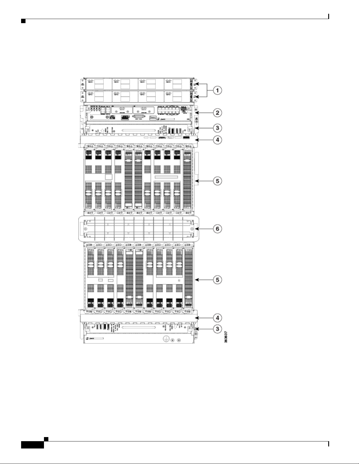
Figure 2-1 shows the front view of the Cisco NCS 4016 chassis.
Figure 2-1 Front View of the Cisco NCS 4016 Chassis
Chapter 2 Chassis Overview
2-2
Cisco Network Convergence System 4000 Series Hardware Installation Guide
Page 17

Chapter 2 Chassis Overview
1 Power trays (2) 4 Fiber management areas (2)
2 External connection unit (ECU)
About the Cisco NCS 4016 Chassis
5 Card cages (2) each containing:
• Craft panel is attached on top of the ECU
(not shown, see Figure 2-2)
• Air outlet is on back (not shown, see
Figure 2-3 and Figure 2-4)
• 8 LC slots
• 2 FC slots (in center)
• 1 RP slot (at side)
3 Fan trays (2) 6 Air inlet
Figure 2-2 shows the partial chassis view with craft panel.
Figure 2-2 Partial Chassis View with Craft Panel
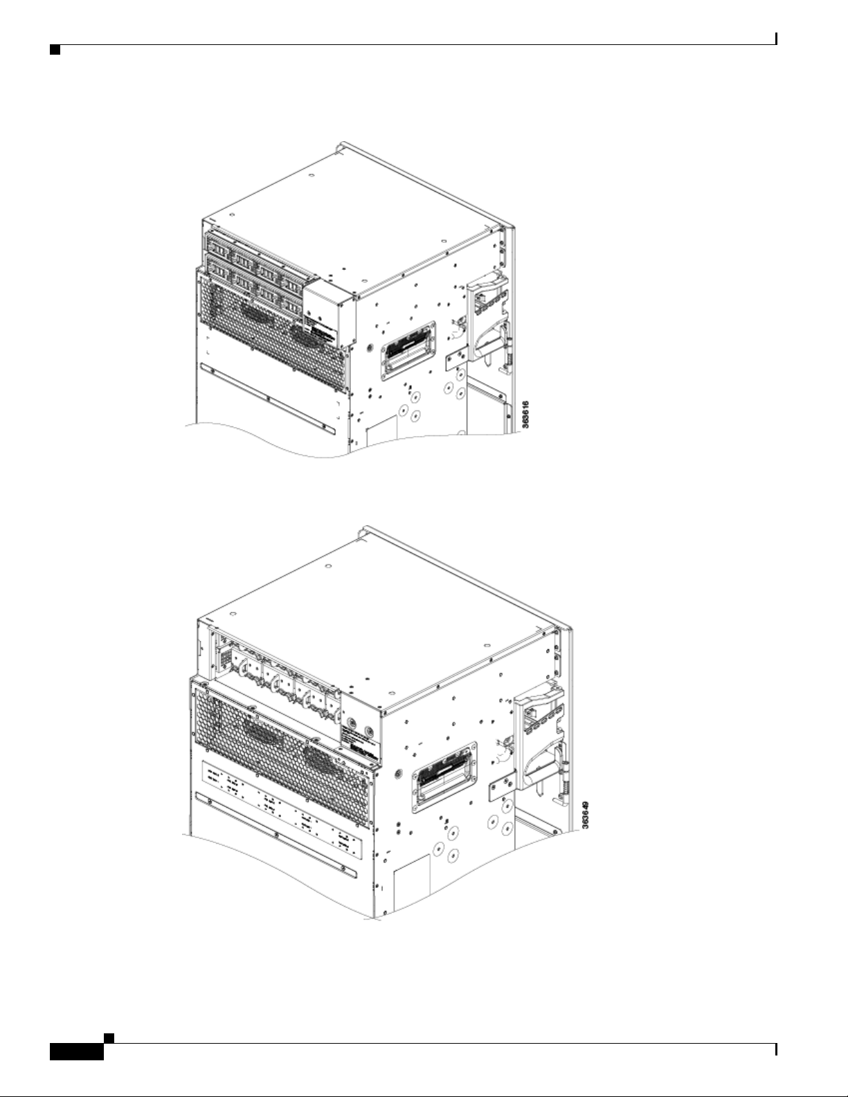
Figure 2-3, Figure 2-4, and Figure 2-5 show partial rear views of the Cisco NCS 4016 chassis.
Note There are two air outlets on the rear of the chassis. One is at the top behind the ECU and one is below
the bottom fan tray.
Cisco Network Convergence System 4000 Series Hardware Installation Guide
2-3
Page 18
About the Cisco NCS 4016 Chassis
Figure 2-3 Rear View of the Cisco NCS 4016 AC Chassis
Chapter 2 Chassis Overview
Figure 2-4 Rear View of the Cisco NCS 4016 DC Chassis
2-4
Cisco Network Convergence System 4000 Series Hardware Installation Guide
Page 19
Chapter 2 Chassis Overview
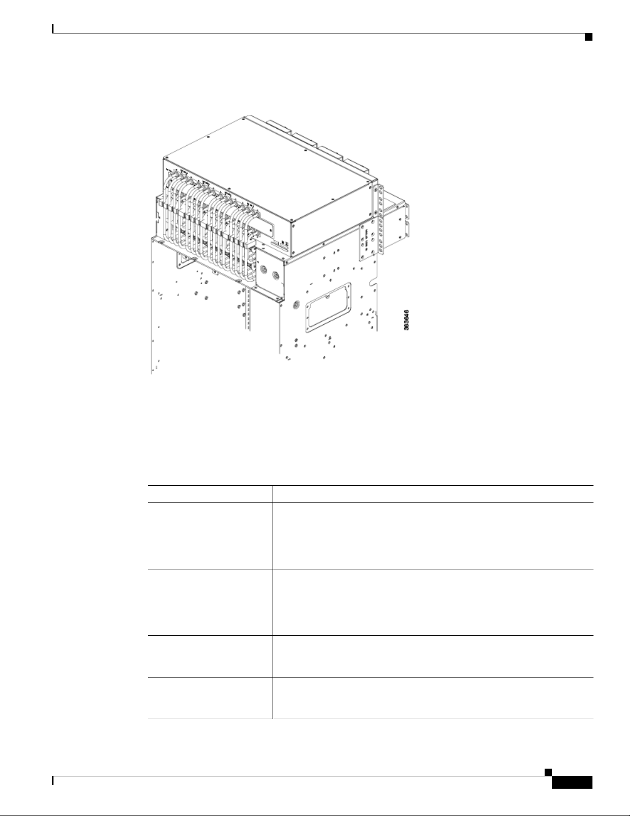
Figure 2-5 Rear View of the Cisco NCS 4016 DC Chassis with DC Power Front Connection
Chassis Components
Adapter
Chassis Components
Table 2-1 lists the main components of the Cisco NCS 4016 chassis.
Table 2-1 Main Components of the Cisco NCS 4016 Chassis
Component Description
route processor cards (RPs) Two RP cards (RP0/RP1) are inserted into the front of the chassis. These
fabric cards (FCs) Four FCs are inserted into the front of the chassis. The FCs provide the
line cards (LCs) As many as sixteen LCs can be inserted into the front of the chassis. These
external connection unit
(ECU)
cards provide the intelligence of the system by functioning as the system
controller and providing route processing and chassis management. The
RP cards also monitor system alarms and control the system fans. The
LEDs on the front panel indicate active alarm conditions.
switch fabric for the routing system and performs the cross-connect
function of the routing system, connecting every LC to each other. The
switch fabric receives ingress user data from one LC slot and performs the
switching necessary to route the data to the appropriate egress LC slot.
cards provide the physical interfaces and optical connections for the user
data.
The ECU provides all shelf electrical I/O connectivity to the active and
standby route-processor line cards. The ECU is located behind the craft
panel.
Cisco Network Convergence System 4000 Series Hardware Installation Guide
2-5
Page 20
Chassis Components
Chapter 2 Chassis Overview
Table 2-1 Main Components of the Cisco NCS 4016 Chassis
Component Description
craft panel The craft panel can install, configure, monitor, and troubleshoot the Cisco
NCS 4016 chassis applications at the node and at the network level. The
craft panel is located on top of the ECU.
fan trays Two fan trays are inserted into the front of the chassis at the top and
bottom. The top fan tray (behind the craft panel) cools the top card rack
and the bottom fan tray covers the bottom card rack. Each fan tray
contains six axial fans. The fans pull cooling air through the chassis from
the front to rear.
air filter Two independent air filters are located in the middle of the chassis behind
the plastic inlet grill. One is dedicated to the top card rack and the other
to the bottom card rack.
We recommend that you change the air filter every three months. The
filter is sold in packs of 5 (Cisco PID NCS4K-FTF=).
power trays Two power trays provide redundant power to the chassis. Both AC and DC
power trays are available. Each power tray holds up to four AC or DC
power modules. A power tray is a field serviceable unit (FSU). A mixture
of AC and DC power is not supported in the chassis.
Note You must power off the chassis before replacing a power tray.
fiber management trays Two fiber management trays are located on the front of the chassis. One
is above the top card rack and the other is below the bottom card rack.
2-6
Cisco Network Convergence System 4000 Series Hardware Installation Guide
Page 21
Chapter 2 Chassis Overview
Chassis Slot Numbers
This section identifies the location and slot numbers for the cards and power modules that plug into the
chassis.
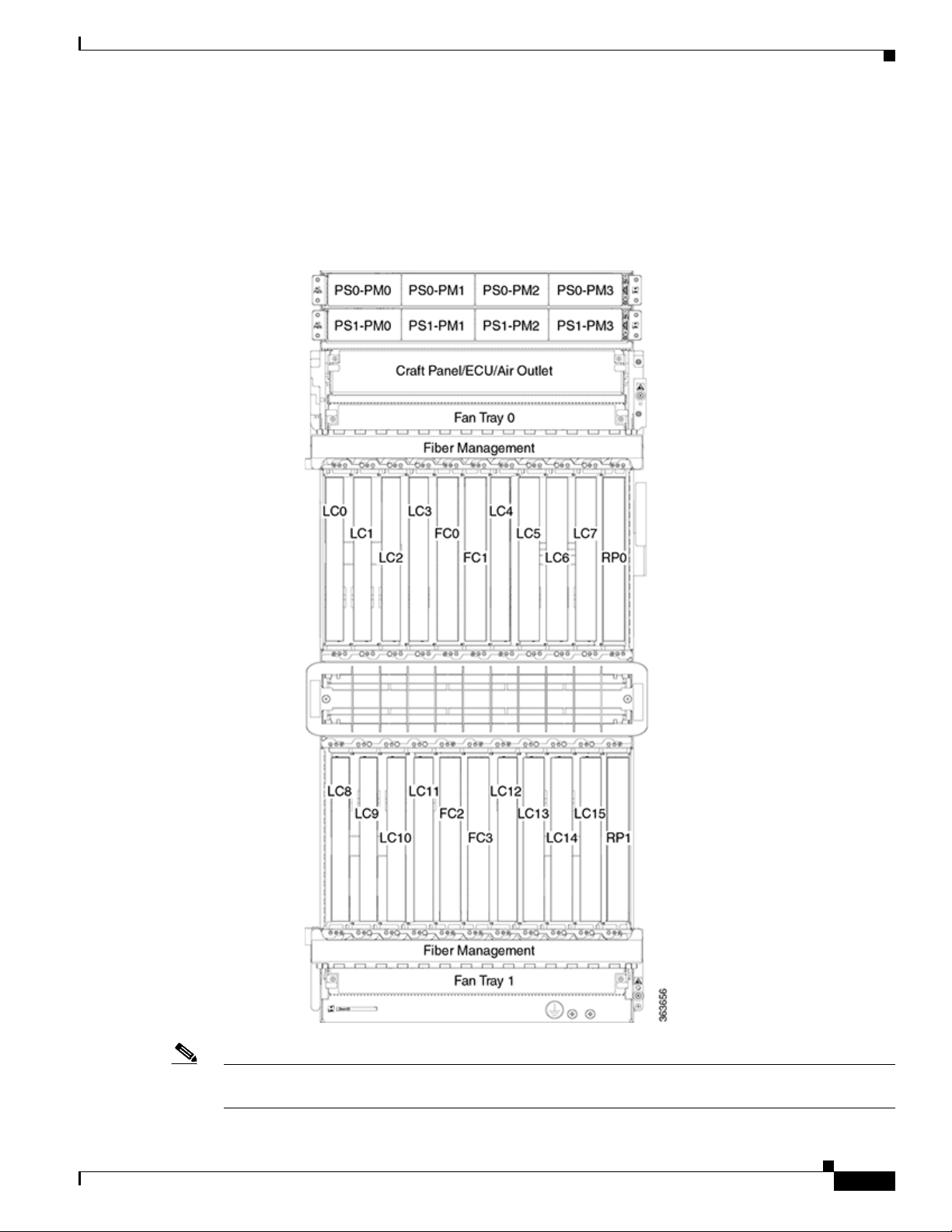
Figure 2-6 Cisco NCS 4016 Chassis Slot Numbers
Chassis Components
Note Cards in the top and bottom card cages are not inserted in the same direction. If you consider the top
cards in Figure 2-6 as a reference, cards in the bottom card cage are inserted upside down.
Cisco Network Convergence System 4000 Series Hardware Installation Guide
2-7
Page 22

Chassis Components
Chapter 2 Chassis Overview
The chassis has the following card slots:
• Sixteen LC slots:
–
Eight in the top card cage (LC0 to LC7)
–
Eight in the bottom card cage (LC8 to LC15)
• Two RP slots:
–
One in the top card cage (RP0)
–
One in the bottom card cage (RP1)
• Four FC slots:
–
Two in the top card cage (FC0, FC1)
–
Two in the bottom card cage (FC2, FC3)
• Two fan trays for redundancy at the top and the bottom of the chassis
• One external connection unit (ECU) located above the top fan tray behind the craft panel
• Two fiber management areas at the top and the bottom of the chassis
• One air inlet and two air outlets
• Eight power modules for redundancy
• The upper four AC or DC power trays (0-3) are contained within power shelf 0 (PS0) and the lower
four AC or DC power trays (4-7) are contained within power shelf 1 (PS1).
The cards have electrical plugs at the back that plug into electrical connectors on the shelf backplane.
When the ejectors are fully closed, the card plugs into the assembly backplane.
The chassis has eight power modules for redundancy:
• The upper four power modules are contained within power tray 0 (PS0). They are named as follows:
PS0-PM0, PS0-PM1, PS0-PM2, and PS0-PM3.
• The lower four power modules are contained within power tray 1 (PS1). They are named as follows:
PS1-PM0, PS1-PM1, PS1-PM2, and PS1-PM3.
Card Slot Requirements
Figure 2-7 shows card installation for the Cisco NCS 4016 chassis.
2-8
Cisco Network Convergence System 4000 Series Hardware Installation Guide
Page 23

Chapter 2 Chassis Overview
Figure 2-7 Installing Cards in the Cisco NCS 4016 Chassis
Chassis Components
The Cisco NCS 4016 chassis has 22 card slots numbered sequentially from left to right. Slots FC0
through FC3 are dedicated to fabric cards. Slots RP0 and RP1 are reserved for route processor cards.
Shelf assembly slots have symbols indicating the type of cards that you can install in them. Each Cisco
NCS 4016 card has a corresponding symbol. The symbol on the card must match the symbol on the slot.
Table 2-2 shows the slot and card symbol definitions.
Table 2-2 Slot and Card Symbols
Symbol Color/Shape Definition
Orange/Circle Slots LC0 through LC15. Only install line cards with a circle symbol on the
faceplate.
Pink/Triangle Slots LC0 through LC15. Only install line cards with circle or a triangle symbol
on the faceplate.
Blue/Hexagon Slots LC0 through LC15. Only install line cards with a blue hexagon symbol on
the faceplate.
Purple/Square Slots RP0 and RP1. Only install route processor cards with a square symbol on
the faceplate.
Lilac/Cross Slots FC0 through FC3. Only install fabric cards with a cross symbol on the
faceplate.
Cisco Network Convergence System 4000 Series Hardware Installation Guide
2-9
Page 24

Chassis Cable Management
Chassis Cable Management
The Cisco NCS 4016 chassis has cable management features for the front side only. The horizontal cable
management brackets are located above and below the card cages.
Safety Guidelines
Before you perform any Cisco NCS 4016 chassis installation procedures, review the safety guidelines in
this section to avoid injuring yourself or damaging the equipment.
Note Review the safety warnings listed in Regulatory Compliance and Safety Information for the Cisco
Network Convergence System 4000 Series before installing, configuring, or troubleshooting any installed
card.
Note Power off the system before removing or installing a power tray.
Chapter 2 Chassis Overview
The following guidelines are for your safety and to protect equipment. The guidelines do not include all
hazards. Be alert.
• Never attempt to lift an object that might be too heavy for you to lift by yourself.
• Keep the work area clear and dust-free during and after installation. Do not allow dirt or debris to
enter into any laser-based components.
• Keep tools and chassis components away from walk areas.
• Do not wear loose clothing, jewelry, and other items that could get caught in the chassis while
working with the chassis and its components.
• Use Cisco equipment in accordance with its specifications and product-usage instructions.
• Do not work alone if potentially hazardous conditions exist.
• Make sure that your installation follows national and local electrical codes: in the United States,
National Fire Protection Association (NFPA) 70, United States National Electrical Code; in Canada,
Canadian Electrical Code, part I, CSA C22.1; in other countries, International Electrotechnical
Commission (IEC) 60364, part 1 through part 7.
• Connect only a DC power source that follows the safety extra-low voltage (SELV) requirements in
UL/CSA/IEC/EN 60950-1 and AS/NZS 60590 to the DC input power system.
• Make sure that you have a readily accessible two-poled disconnect device incorporated in the fixed
configuration wiring of a DC input power system.
• Make sure that you provide short-circuit (overcurrent) protection as part of the building installation.
2-10
Cisco Network Convergence System 4000 Series Hardware Installation Guide
Page 25
Chapter 2 Chassis Overview
Preventing Electrostatic Discharge
Electrostatic discharge (ESD) damage, which can occur when electronic cards or components are
improperly handled, results in complete or intermittent failures. We recommend use of an
ESD-preventive wrist strap whenever you handle network equipment or one of its components.
Following are guidelines for preventing ESD damage:
• Always use an ESD-preventive wrist or ankle strap, and ensure that it makes good skin contact.
Connect the equipment end of the connection cord to an ESD jack (Figure 2-8 and Figure 2-9) or a
bare metal surface on the chassis (ensure the chassis is grounded).
• Handle a card by its ejector levers, when applicable, or its metal carrier only; avoid touching the
board or connector pins.
• Place a removed card board side up on an antistatic surface or in a static-shielding bag. If you plan
to return the component to the factory, immediately place it in a static-shielding bag.
• Avoid contact between a card and clothing. The wrist strap protects the board from only ESD voltage
on the body; ESD voltage on clothing can still cause damage.
Figure 2-8 shows the ESD jacks on the top of the chassis.
Safety Guidelines
Figure 2-8 ESD Jacks—Top of Chassis
1 Top ETSI connection point 2 Top ANSI jacket point
Cisco Network Convergence System 4000 Series Hardware Installation Guide
2-11
Page 26
Safety Guidelines
Chapter 2 Chassis Overview
Figure 2-9 shows the ESD jacks on the bottom of the chassis.
Figure 2-9 ESD Jacks—Bottom of Chassis
1 Bottom ANSI jacket point 2 Bottom ETSI connection point
2-12
Cisco Network Convergence System 4000 Series Hardware Installation Guide
Page 27

CHA PTER
3
Site Planning Considerations
This chapter describes the general considerations to address while planning for the installation of the
Cisco NCS 4016 chassis. As you plan for your system, keep in mind the specifications listed in
Appendix B, “System Specifications.”
This chapter includes the following sections:
• Basic Site and Installation Planning, page 3-1
• Equipment Rack Considerations, page 3-2
• Aisle Spacing and Maintenance Access Floor Plan, page 3-3
• Cable Management, page 3-4
• Noise Control, page 3-5
• Cisco Installation Services, page 3-5
• System Testing, Certification, and Warranties, page 3-5
Basic Site and Installation Planning
As you plan for basic site and installation requirements, consider the following:
• Does the installation site have adequate power for the routing system?
• Can the routing system be positioned close to the AC or DC power source, and are the power
receptacles easy to reach?
• Does the site have appropriate equipment racks with space available in which to install the system?
Are additional equipment racks required?
• Is there a scissor lift or similar lifting device available to lift the chassis into the equipment rack?
In addition, make sure that the installation site meets the following access requirements:
• At least 36 inches (92 cm) of clearance exists between rows of equipment racks. This space is needed
to access components in the chassis. Additional clearance may be necessary for installation.
• Enough room exists for the system console terminal, and that the console cable is long enough to
reach the routing system from the terminal.
• Fan tray exhaust vents are not blocked, and airflow at the bottom of the chassis is not blocked.
When planning the site, you should think about potential expansion of the system. Consider the
following:
• Equipment rack space for additional chassis
Cisco Network Convergence System 4000 Series Routers Site Planning Guide
3-1
Page 28

Equipment Rack Considerations
122781
CISCO CRS-1
SERIES
LINECARD CHASSIS
1
2
3
4
• Power and cooling requirements for additional chassis
• Cable management for routing system cables
Equipment Rack Considerations
A fully loaded Cisco NCS 4016 chassis weighs 412 lb (187 kg). The chassis is mounted in a two-post or
a four-post rack. Figure 3-1 shows a four-post rack.
Figure 3-1 Cisco NCS 4016 Chassis Mounted in an Equipment Rack
Chapter 3 Site Planning Considerations
1 Equipment rack 3 Vertical mounting brackets
2 Cisco NCS 4016 chassis 4 Horizontal mounting brackets
3-2
Cisco Network Convergence System 4000 Series Routers Site Planning Guide
Page 29

Chapter 3 Site Planning Considerations
Aisle Spacing and Maintenance Access Floor Plan
Warning
Note We recommend that you use a scissor lift or similar lifting device to position the chassis in the rack and
The chassis should be mounted on a rack that is permanently affixed to the building.
Statement 1049
to hold the chassis in place while you bolt it to the rack. A forklift is not recommended for this purpose.
As you plan the installation of the chassis into the equipment rack, consider the following:
• Make sure that the floor mounting bolts on the equipment rack are accessible, especially if annual
retorquing of bolts is required.
• For chassis installation, you must have access to the vertical mounting rails at each corner of the
equipment rack.
• Consider whether the area around the rack is large enough to accommodate the scissor lift (or similar
lifting device) and installation personnel.
• A minimum of 48 mounting screws (10-32 x 5/8 in. socket head cap screws are provided with the
chassis) are needed to secure the chassis to the rack. To secure the chassis to the rack, install twelve
screws on each of the four vertical mounting brackets.
Note If you plan to use mounting screws other than the ones shipped with the chassis, you can use
10-32, 10-24, 12-24, or M5 screws. (M6 and 1/4-20 screws do not fit.)
• The rack should have horizontal shelf brackets to place the chassis on. The brackets must be able to
support at least 650 lb. (294.8 kg). If the rack does not have horizontal mounting rails, a set of rails
is included in the installation kit, which is available as an option (NCS4K-INST-KIT=).
Caution Standard rack-mounting screws are not strong enough to secure the chassis to the equipment rack.
Use only those mounting screws that are shipped with the chassis.
For complete instructions on mounting and securing the chassis to a rack, see the Cisco Network
Convergence System 4000 Series Routers Unpacking, Moving, and Securing Guide.
Aisle Spacing and Maintenance Access Floor Plan
The floor plan for the Cisco NCS 4016 chassis must include enough space to install the chassis in the
equipment rack and allow sufficient airflow for the system. The floor plan must also provide enough
room to access chassis components for maintenance (for example, to remove fan trays, power modules,
cables, and air filters).
Note For chassis installation, make sure that enough room exists in front of the chassis to accommodate
installation personnel and the scissor lift (or similar lifting device) used to hold the chassis in the rack
while it is bolted in.
Cisco Network Convergence System 4000 Series Routers Site Planning Guide
3-3
Page 30

Cable Management
Front and Rear Clearances
The site requires the following front and rear clearances for chassis installation and maintenance access:
• To install the chassis in the equipment rack: approximately 40 inches (101.6cm)
• To service components and allow system airflow (both in front of and behind the chassis): 36 inches
(91.4 cm)
Note Maintain at least 6 inches (15.2 cm) of clearance at both the inlet and exhaust openings on the
chassis and on the power modules to allow sufficient airflow.
Cable Management
As the size of the routing system increases, the cabling required for the chassis increases. For example,
a fully loaded Cisco NCS 4016 chassis has more cables connected to it than a partially loaded chassis.
The cabling runs must be carefully planned. The basic configurations for various routing systems should
be arranged to minimize the complexity and length of the cable runs. Precut and terminated cables are
considered part of the basic configuration.
Chapter 3 Site Planning Considerations
• CONSOLE or AUX RJ-45 RS-232 serial ports on the route processor cards for terminal connections
• Ethernet ports on the route processor cards for connecting network management equipment
• Modular service cards (MSCs) and physical layer interface modules (PLIMs) for data connections
The upper and lower cable management trays are for organizing these interface cables to keep the front
of the chassis clear and to eliminate sharp bends in the cables.
Caution Excessive bending can damage interface cables.
Route Processor Cables
As you consider system cabling, see Ta b le 3- 1 to determine the types of cables required to connect to
ports on the route processor (RP).
Table 3-1 Route Processor Cables
RP Port Required Cable Type
Ethernet management STP
Alarm Shielded cable. Required for EMC compliance.
1. STP = shielded twisted-pair
1
cable (Category 5 or better). Required for enhanced immunity
to external electromagnetic disturbance levels of 10 V/m and
10 Vrms.
3-4
Cisco Network Convergence System 4000 Series Routers Site Planning Guide
Page 31

Chapter 3 Site Planning Considerations
Interface Cables
You must provide the interface cables. Because the type and number of interfaces can vary, plan these
cable runs prior to the installation. When planning the cable runs, consider the following:
• Number and type of interface connections (OC-48/STM-16 or STS-48, OC-192/STM-64 or
STS-192, OC-768/STM-256 or STS-768, 10-Gigabit Ethernet, and 100-Gigabit Ethernet)
• Termination at the other end of the cables (such as patch panel or optical transport equipment)
• Proper length and termination of cables
Noise Control
The Cisco NCS 4016 chassis has some built-in noise reduction, such as fan speed control. If the routing
system is installed in an environment where excessive noise could be harmful to personnel, some other
noise reduction options could be attempted. Passive noise reduction could include the installation of
foam panels to insulate the surrounding area from the noise.
Additional noise-reduction measures have to be designed on an individual site basis.
Noise Control
Cisco Installation Services
Cisco or a Cisco partner can provide a complete installation, from planning to power up. For information
about Cisco or Cisco partner installation services, consult Cisco Customer Advocacy.
System Testing, Certification, and Warranties
After the routing system has been installed, it must be tested and certified. Consult Cisco Customer
Advocacy for information about testing, certification, and warranties.
Cisco Network Convergence System 4000 Series Routers Site Planning Guide
3-5
Page 32

System Testing, Certification, and Warranties
Chapter 3 Site Planning Considerations
3-6
Cisco Network Convergence System 4000 Series Routers Site Planning Guide
Page 33

CHA PTER
4
Installing Power Components
This chapter provides instructions on how to install and reinstall power components in the
Cisco NCS 4016 chassis. It also covers connecting and disconnecting power and powering on the
chassis.
Note The Cisco NCS 4016 chassis ships with power trays and power modules installed.
This chapter presents the following topics:
• Power Connection Guidelines, page 4-1
• Installing the Chassis Ground Cable, page 4-8
• Installing an AC or DC Power Tray, page 4-11
• Installing Power Modules, page 4-12
• Installing the DC Power Front Connection Adapter, page 4-15
• Connecting Power to the Chassis, page 4-23
• Disconnecting AC or DC Power, page 4-28
• Powering On the Chassis, page 4-30
Power Connection Guidelines
You can configure the chassis with either an AC input or DC input power subsystem, so the site power
source requirements differ depending on the power subsystem in your chassis. Ensure all power
connection wiring conforms to the rules and regulations in the National Electrical Code (NEC) as well
as local codes.
Each power tray includes 4 power modules each. The chassis has two power trays for redundancies (each
tray can provide the full power to the chassis). The power tray provides electrical connections to the
chassis backplane. Each power module can be individually plugged in or out from the tray.
Caution Each Cisco NCS 4016 chassis is powered by only one type of input: AC or DC. A hybrid (AC+DC) power
configuration is not supported.
Cisco Network Convergence System 4000 Series Hardware Installation Guide
4-1
Page 34

Power Connection Guidelines
Caution Proper grounding is necessary to avoid damage from lightning and power surges. See the “NEBS
Supplemental Unit Bonding and Grounding Guidelines” section on page 4-6 for grounding
requirements.
AC-Powered Chassis
AC power modules operate in the input range of 180 VAC to 264 VAC, 47 to 63 Hz (nominal input level
of 200 to 240 VAC).
Power redundancy requirements vary based on the system configuration (number and type of line cards,
etc.). AC-powered systems are 2N protected. A minimum of two power supplies are required for
redundant operation.
Each of the AC power inputs requires a separate dedicated branch circuit. Note that the circuit breaker
and fuse lockout procedures should follow the rules and regulations in the National Electrical Code
(NEC) and any local codes. For a list of the nominal and acceptable value ranges for source AC power,
see Tabl e B-2.
Chapter 4 Installing Power Components
The Cisco NCS 4016 chassis supports two types of AC power cords: International and NEMA (USA).
Figure 4-1 International AC Power Cord (Cisco PID NCS4K-AC-CBL-IEC)
Figure 4-2 NEMA AC Power Cord (Cisco PID NCS4K-AC-CBL-NEMA)
Note Before connecting AC input power cords to the power system, make sure that the power cords are not
energized.
DC-Powered Chassis
4-2
Use a 6 AWG wire rated 75°C minimum, for DC power modules connection. The system accepts a
nominal input voltage of -48 VDC or -60VDC, with an operational tolerance range of -40.5 to -72 VDC.
One dedicated, commensurately rated DC power source is required for each power module connection.
Each power feed shall be provided with a double pole breaker, rated not more than 60A, with medium
delay.
Cisco Network Convergence System 4000 Series Hardware Installation Guide
Page 35

Chapter 4 Installing Power Components
Note Follow the power and sizing requirements for your site.
Note The Short Circuit protection Breaker shall not be rated more than 60A.
Power redundancy requirements vary based on the system configuration (number and type of line cards,
etc.). DC-powered systems are N+1 protected.
Power connections to the power tray for each DC power module requires four cables: two source cables
and two return cables.
For DC power cables, we recommend 6 AWG high-strand-count copper wire cables, rated 75°C
minimum. The size of the cables depends on your chassis location from the source power. Follow your
local practices for determining cable size. DC power cables are not available from Cisco, but they are
available from any commercial cable vendor.
You must terminate DC power cables using cable lugs at the power tray end. The appropriate lugs are
provided in the installation kit with 6 AWG cable. Use Panduit part number LCD4-14AF-L or the
equivalent.
Power Connection Guidelines
Warning
Warning
Note Before connecting DC power cables to the power system, make sure that the input power cords are not
Hazardous voltage or energy may be present on power terminals. Always replace cover when
terminals are not in service. Be sure uninsulated conductors are not accessible when cover is in
place.
Statement 1086
Only trained and qualified personnel should be allowed to install, replace, or service this equipment.
Statement 1030
energized.
Note Ensure that there is a readily accessible disconnect device incorporated in the building’s installation
wiring.
Note Circuit breaker and fuse lockout procedures should follow the rules and regulations in the National
Electrical Code (NEC) and any local codes.
Figure 4-3 shows the lug type required for DC input cable connections.
Cisco Network Convergence System 4000 Series Hardware Installation Guide
4-3
Page 36

Power Connection Guidelines
364880
Figure 4-3 Typical DC Power Cable Lugs
Chapter 4 Installing Power Components
Warning
To avoid shock hazard, be sure to apply shrink wrap tubing around the wire entry area of the lug.
The color coding of source DC power cable leads depends on the color coding of the site DC power
source. Because there is no color code standard for source DC wiring, be sure that power source cables
are connected to the power modules using the proper positive (+) and negative (–) polarity:
• In some cases, the source DC cable leads might have a positive (+) or a negative (–) label. This is a
relatively safe indication of the polarity, but you must verify the polarity by measuring the voltage
between the DC cable leads. Be sure that the positive (+) and negative (–) cable leads match the
positive (+) and negative (–) labels on the power module when making the measurement.
• A green (or green and yellow) cable typically indicates that it is a ground cable.
Caution DC power modules contain reverse voltage protection circuitry to prevent damage to the power module
if it detects a reverse polarity condition. No damage should occur from reverse polarity, but you should
correct a reverse polarity condition immediately.
For a list of the nominal and acceptable value ranges for source DC power, see Appendix B, “System
Specifications.”
4-4
Cisco Network Convergence System 4000 Series Hardware Installation Guide
Page 37

Chapter 4 Installing Power Components
General Power and Grounding Requirements
General Power and Grounding Requirements
This section describes the power and grounding requirements you must consider when planning the site
facilities for the routing system. In addition, see the “DC Power Requirements” section on page 4-5 or
the “AC Power Requirements” section on page 4-6 for additional information about the power
requirements for your chassis type.
Note A qualified electrician should review the information in these sections to ensure that the installation site
meets these requirements. For larger system configurations, consult a facilities electrical expert to
understand the load that the routing system may put on the facility power plant.
General power and grounding requirements are:
• Installation of the routing system must follow national and local electrical codes:
–
In the United States: United States National Fire Protection Association (NFPA) 70 and United
States National Electrical Code (NEC).
–
In Canada: Canadian Electrical Code, part I, CSA C22.1.
–
In other countries: International Electrotechnical Commission (IEC) 60364, parts 1 through 7.
• Two separate and independent AC or DC power sources are needed to provide 2N redundancy for
system power. Each power source requires its own circuit breaker.
• Each power source must provide clean power to the site. If necessary, install a power conditioner.
• The site must provide short-circuit (over-current) protection for devices.
• Proper grounding is required at the site to ensure that equipment is not damaged by lightning and
power surges. In addition:
–
Chassis grounding is required for AC and DC-powered systems.
–
For AC-powered systems, a grounding-type AC power outlet is required.
• Site power planning must include the power requirements for any external terminals and test
equipment you will use with your system.
Note Be sure to review the safety warnings in the Cisco Network Convergence System Regulatory Compliance
and Safety Information for the Cisco Network Convergence System 4000 Series Routers before
attempting to install the routing system.
DC Power Requirements
Observe the following guidelines for DC-powered shelves. In addition, be sure to review the
requirements described in the “General Power and Grounding Requirements” section on page 4-5.
• A DC-powered chassis requires up to a maximum of 12,250 watts of DC input power when the
chassis is fully loaded.
• All power connection wiring must conform to the rules and regulations in the National Electrical
Code (NEC) and any local codes. In addition, make sure that the wiring conforms to any internal
requirements at the installation site.
• Each DC power source must comply with the safety extra-low voltage (SELV) requirements in
UL 60950-1, CSA-C22.2 No. 60950-1, EN60950-1, AS/NZS 60950, and IEC60950-1.
Cisco Network Convergence System 4000 Series Hardware Installation Guide
4-5
Page 38

General Power and Grounding Requirements
• A DC-powered system should be installed in a restricted access area in accordance with the
National Electric Code, ANSI/NFPA 70.
• All components in the area where DC input power is accessible must be properly insulated.
If it is not possible to rely on the identification of the earthed conductor in the DC mains supply, whereby
the equipment is not provided with a two-pole disconnect device, then a two-pole disconnect device is
to be provided external to the equipment.
AC Power Requirements
In addition to the requirements in the “General Power and Grounding Requirements” section on
page 4-5, AC input power requirements are as follows:
• An AC-powered chassis requires up to a maximum of 12,000 watts of AC input power when the
chassis is fully loaded.
• Two separate and independent AC power sources are required for N+N redundancy, one for each
power shelf. Each power shelf should be connected to a different power source to provide 2N power
redundancy in case a power source fails. The system will operate with power to only one shelf but
will not have N+N redundancy.
Chapter 4 Installing Power Components
• Each AC power source must provide single-phase AC power, and have its own circuit breaker.
• The AC power receptacles used to plug in the chassis must be the grounding type. The grounding
conductors that connect to the receptacles should connect to protective earth ground at the service
equipment.
• AC single-phase input:
–
Single-phase, 200 to 240 VAC nominal, 50 to 60 Hz, 17A maximum.
–
Each AC power shelf contains four specific single phase AC inlet connectors. These connectors
can accept four AC power cords provided by Cisco. AC power cords provided by Cisco can have
a IEC-309 plug 32A rated for International power systems, or a NEMA L6-30P plug 30A rated
for North America Power Systems.
Note The external breaker current rating can be less than 30A, depending on the chassis
configuration. Please refer to the national installation rules for the correct rating of the
breakers or fuses.
NEBS Supplemental Unit Bonding and Grounding Guidelines
You must connect the central office ground system or interior equipment grounding system permanently
to one of the two supplemental bonding and grounding connections on the back or side of the chassis to
meet Network Equipment Building System (NEBS) requirements as well as safety compliance
requirements. These grounding points are referred to as the NEBS bonding and grounding points
4-6
Cisco Network Convergence System 4000 Series Hardware Installation Guide
Page 39

Chapter 4 Installing Power Components
Note These bonding and grounding connections satisfy the Telcordia NEBS requirements for supplemental
bonding and grounding connections. If you are not installing the chassis in a NEBS environment, you
can choose to bypass these guidelines and rely on the safety earth ground connections to the AC power
modules.
Figure 4-4 shows the NEBS bonding and grounding points on the NCS 4016 chassis.
Figure 4-4 NEBS Bonding and Grounding Points on the Cisco NCS 4016 Chassis
General Power and Grounding Requirements
1 NEBS grounding point on front of chassis
Cisco Network Convergence System 4000 Series Hardware Installation Guide
4-7
Page 40

Installing the Chassis Ground Cable
Chapter 4 Installing Power Components
1 NEBS grounding point on right side of the
chassis
3 Lock washers
To ensure a satisfactory supplemental ground connection to the chassis, use the following parts:
• One grounding lug, which has two M6 bolt holes with 0.625- to 0.75-inch (15.86- to 19.05-mm)
spacing between them, and a wire receptacle able to accept a 2-4-AWG or larger, multistrand copper
wire. This lug is similar to those used for the DC input power supply leads (see Figure 4-3).
• Two M6 round-head screws and two locking washers (nickel-plated brass is ideal).
• One grounding wire. Although we recommend at least 2-4-AWG multistrand copper wire, the wire
diameter and length depend on your chassis location and site environment.
Note These parts are not available from Cisco (with the exception of the grounding lug), but they are available
from commercial vendors.
Installing the Chassis Ground Cable
This section describes how to install a ground cable to either NEBS bonding and grounding point on the
front or side of the Cisco NCS 4016 chassis.
2 Screws
4-8
Required Tools and Equipment
• Ground lug and screws (provided in chassis accessory kit)
• Ground cable
• Crimping tool and lug specific die
• 3/8-inch drive socket wrench
• 3/8-inch drive torque wrench rated to include 35 in-lb (3.95 N-m).
Cisco Network Convergence System 4000 Series Hardware Installation Guide
Page 41

Chapter 4 Installing Power Components
To ensure a satisfactory ground connection, we recommend 2-4-AWG multistrand copper ground cable.
This cable is not available from Cisco; it is available from any commercial cable vendor such as Panduit.
The cable should be sized according to local and national installation requirements.
Note The DC return of this system should remain isolated from the system frame and chassis (DC-I: Isolated
DC Return).
Figure 4-5 Straight Barrel Grounding Lug
0.59
0.51
0.27
0.23
0.29
0.25
1.01
0.99
Installing the Chassis Ground Cable
2.74
2.62
(2) Plcs.
Beveled Wire
Entry
Wire Inspection
1.62 MIN
0.10
0.08
All measurements in inches.
Window
0.85
0.77
Color Coded
Barrel Markings
0.29
0.27
I.D.
0.39
0.37
364442
Steps
To attach the ground cable to the chassis, perform the following steps:
Step 1 Use the crimping tool mandated by the lug manufacturer to crimp the lug to the ground cable.
Step 2 Use the socket wrench to attach the lug and ground cable to either grounding point (Figure 4-6 and
Figure 4-7).
Note The two grounding point screws are required for proper bonding and grounding of the chassis
and should not be removed.
Cisco Network Convergence System 4000 Series Hardware Installation Guide
4-9
Page 42

Installing the Chassis Ground Cable
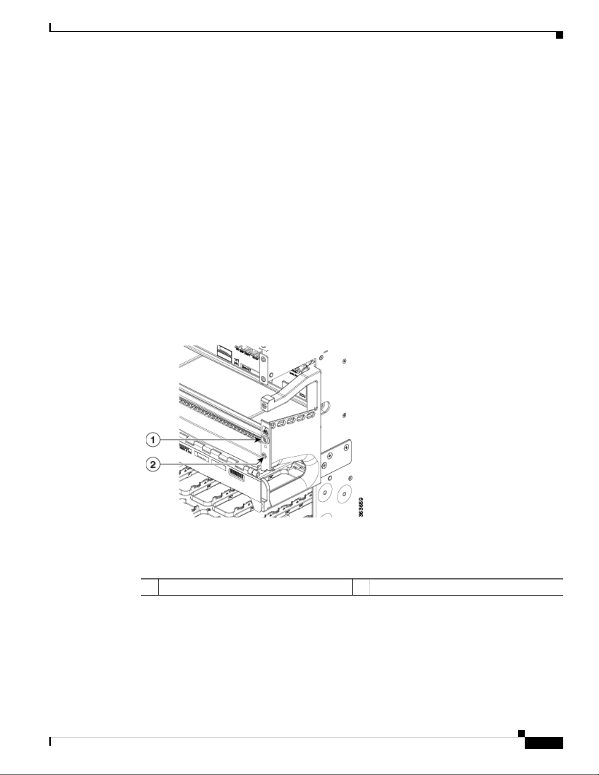
Figure 4-6 Attaching to Front NEBS Bonding and Grounding Point
Chapter 4 Installing Power Components
363918
1
2
1 Screws 2 Lock washers
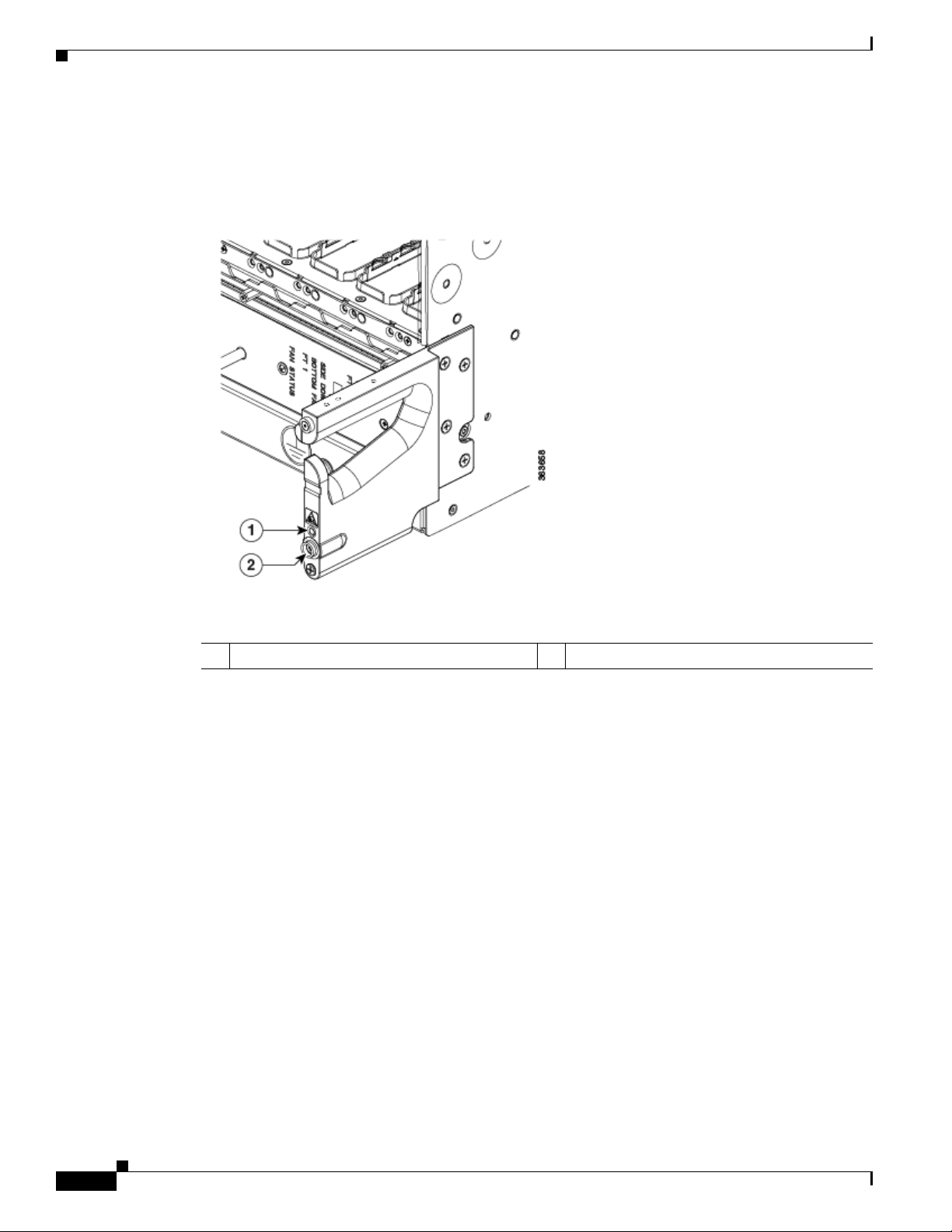
Figure 4-7 Attaching to Side NEBS Bonding and Grounding Point
1 NEBS grounding point on right side of the
2 Screws
chassis
3 Lock washers
4-10
Step 3
Cisco Network Convergence System 4000 Series Hardware Installation Guide
Use the torque wrench to tighten the bolts to a torque of 35 in-lb (3.95 N-m).
Page 43

Chapter 4 Installing Power Components
Step 4 Connect the other end of the ground cable to a grounding point at your site, according to site
requirements.
Installing an AC or DC Power Tray
The power tray is preinstalled on the Cisco NCS 4016 chassis. The following procedure describes how
to install an AC or DC power tray in the chassis.
Required Tools and Equipment
• 6-inch, number-1 Phillips screwdriver
• Cisco NCS 4016 power trays (NCS4K-AC-PEM or NCS4K-DC-PEM)
Steps
Follow these steps to install an AC or DC power tray into the chassis:
Installing an AC or DC Power Tray
Step 1 Slide the power tray into the bay until it engages its mating connector on the chassis.
Step 2 Fully seat the power tray into its mating connector and seat the power tray mounting ears against the
chassis mounting ears.
Step 3 Install and tighten two screws (for each power tray) through the power tray mounting ears on each side
into the screw holes in the chassis mounting ears to secure the tray to the chassis.
Cisco Network Convergence System 4000 Series Hardware Installation Guide
4-11
Page 44

Installing Power Modules
Figure 4-8 Screws on Power Tray Mounting Ears
Chapter 4 Installing Power Components
1 Screws on the power tray mounting ears
Installing Power Modules
The following procedures describe how to install power modules into the chassis. The installation
procedure is the same for both AC or DC modules.
Caution Never force a power module into the power tray if you feel any resistance! The power modules are keyed
to prevent AC modules from being plugged into a DC power tray or a DC module into an AC power tray.
Forcing a module into the incorrect tray can cause damage to the module and the tray.
Each power module has three status LEDs located on the front left side of its faceplate.
4-12
Cisco Network Convergence System 4000 Series Hardware Installation Guide
Page 45

Chapter 4 Installing Power Components
Table 4-1 Power Module LED Status Indicator Lights
LED Name Color Meaning
Input OK Green
Output OK Green
Fault Red
• On: The input voltage is present and within regulation range.
• Blinking: The input voltage is present but out of regulation range.
• Off: The input voltage is not present.
• On: The output voltage is on.
• Blinking: The power module is in a power limit or over current
• Off: The output voltage is off.
• On: An internal fault is detected within the power module.
• Off: No internal faults detected on the power module.
Installing AC or DC Power Modules
Installing Power Modules
condition.
The following section describes how to install AC or DC power modules.
Required Tools and Equipment
• Cisco NCS 4016 power modules (NCS4K-AC-PSU=)
• Cisco NCS 4016 power modules (NCS4K-DC-PSU-V1)
Steps
Caution To prevent damage to the power tray backplane connector, do not use excessive force when inserting the
power module into the power tray.
Follow these steps to install the AC or DC power modules into the chassis:
Step 1 Remove the filler caps from the slots where you want to install the power modules.
Step 2 Using two hands to support the power module, slide it into the power tray.
Cisco Network Convergence System 4000 Series Hardware Installation Guide
4-13
Page 46

Installing Power Modules
Figure 4-9 Example of Inserting the AC Power Module
Chapter 4 Installing Power Components
4-14
Step 3
Cisco Network Convergence System 4000 Series Hardware Installation Guide
Secure the power module into the power tray using the snap hook.
Page 47

Chapter 4 Installing Power Components
Figure 4-10 Example of Securing the Snap Hook (AC)
Installing the DC Power Front Connection Adapter
Step 4
Repeat these steps for the other AC or DC power modules.
Installing the DC Power Front Connection Adapter
If you have limited access to the back of the chassis, or limited space behind the chassis, you can use the
DC Power Front Connection Adapter. This DC adapter moves the DC power connections from the back
of the chassis to the front of the chassis. This may be desirable in ETSI rack installations.
Cisco Network Convergence System 4000 Series Hardware Installation Guide
4-15
Page 48

Installing the DC Power Front Connection Adapter
Figure 4-11 DC Power Front Connection Adapter
Chapter 4 Installing Power Components
Prerequisites
• If the rear to front power adapter is going to be used, then the sub assembly needs to be attached first
to the chassis and then both units installed in a rack or cabinet.
• The Cisco NCS 4016 chassis should be completely removed from the packaging and installed in the
rack or cabinet.
Required Tools and Equipment
• 6-inch, number-1 Phillips screwdriver
• One DC Power Front Connection Adapter (NCS4K-DC-FA, includes brackets)
• 3/8 Ratchet Wrench, 7/16 Socket, and a Torque Wrench
Steps
Step 1 Install the DC-FA (front access) brackets on the sides toward the front of the DC adapter. There are three
different types of bracket depending upon rack type: ANSI 19 inch or 23 inch and ETSI. Choose the
correct type for your specific rack (Figure 4-12).
4-16
Cisco Network Convergence System 4000 Series Hardware Installation Guide
Page 49

Chapter 4 Installing Power Components
Figure 4-12 Installing the DC-FA Brackets
Installing the DC Power Front Connection Adapter
Step 2
Attach the rear cable guide on top of the chassis toward the rear, and attach the insulator sheet on top of
the chassis toward the front (Figure 4-13).
Cisco Network Convergence System 4000 Series Hardware Installation Guide
4-17
Page 50

Installing the DC Power Front Connection Adapter
Figure 4-13 Attaching Rear Cable Guide and Insulator Sheet
Chapter 4 Installing Power Components
4-18
1 Rear cable guide 2 Insulator sheet
Step 3
Place the DC adapter on top of the chassis using the embossed references on the top chassis cover
(Figure 4-14).
Cisco Network Convergence System 4000 Series Hardware Installation Guide
Page 51

Chapter 4 Installing Power Components
Figure 4-14 Placing DC Adapter on Top of Chassis
Installing the DC Power Front Connection Adapter
Step 4
Connect the power cables on the rear of the of DC adapter to the chassis terminal blocks (Figure 4-15).
Follow the connections scheme as shown on the labels available on the DC adapter and the chassis.
Cisco Network Convergence System 4000 Series Hardware Installation Guide
4-19
Page 52

Installing the DC Power Front Connection Adapter
Figure 4-15 Connecting Power Cables
Chapter 4 Installing Power Components
4-20
1 Connect power cables to chassis terminal blocks
Step 5 Install the rear cover to protect the cables (Figure 4-16).
Cisco Network Convergence System 4000 Series Hardware Installation Guide
Page 53

Chapter 4 Installing Power Components
Figure 4-16 Installing the Rear Cover
Installing the DC Power Front Connection Adapter
Step 6
Install the chassis and DC adapter subassembly in the rack or cabinet. Attach the chassis brackets and
DC brackets to the rack (Figure 4-17).
Cisco Network Convergence System 4000 Series Hardware Installation Guide
4-21
Page 54

Installing the DC Power Front Connection Adapter
Figure 4-17 Chassis Brackets and DC Adapter Brackets
Chapter 4 Installing Power Components
4-22
1 DC adapter brackets 2 Chassis brackets (one on other side is not
visible)
Step 7 Connect the power cables coming from batteries or from the PDU unit to the DC adapter terminal blocks
on the front side of the unit (Figure 4-18). See the “Connecting Power to the Chassis” section on
page 4-23.
Cisco Network Convergence System 4000 Series Hardware Installation Guide
Page 55

Chapter 4 Installing Power Components
Figure 4-18 Connecting Power Cables to Terminal Blocks
Connecting Power to the Chassis
1 Terminal Blocks
Connecting Power to the Chassis
Use one of the following procedures to connect power to your chassis:
• Connecting Power to an AC-Powered Chassis, page 4-23
• Connecting Power to a DC-Powered Chassis, page 4-25
Connecting Power to an AC-Powered Chassis
Follow these steps to connect the AC power cords to the chassis.
Note Connect each AC power supply to a dedicated power source (branch circuit). Each AC input power
supply operates at a nominal input level of 200 to 240 VAC.
Cisco Network Convergence System 4000 Series Hardware Installation Guide
4-23
Page 56

Connecting Power to the Chassis
Step 1 Check that the power switch is set to the OFF (0) position. The power switch is on the right of the power
tray.
Step 2 Check that the circuit breaker assigned to the AC power source you are connecting is set to off.
Step 3 Verify that the permanent ground connection (central office grounding system) has been installed to the
NEBS grounding location on the chassis.
Chapter 4 Installing Power Components
Warning
To ensure that power remains off while you are performing this procedure, lock-out/tag-out the circuit
breaker switch in the OFF (0) position until you are ready to turn it on.
Step 4 Plug the AC power cord into the receptacle at the rear of the AC power tray.
Step 5 Tighten the screw that clamps the AC power cord plug in place.
Figure 4-19 Typical AC Power Connections to an AC Power Tray
4-24
Step 6
Step 7 Proceed to the “Powering On the Chassis” section on page 4-30.
Cisco Network Convergence System 4000 Series Hardware Installation Guide
Plug the other end of the AC power cord into the AC source receptacle.
Page 57

Chapter 4 Installing Power Components
Connecting Power to a DC-Powered Chassis
This section contains the procedures to connect the DC source power cables to a DC-powered chassis.
The color coding of source DC power cable leads depends on the color coding of the site DC power
source. Because there is no color code standard for source DC wiring, you must be sure that power
source cables are connected to the power module with the proper positive (+) and negative (–) polarity:
• In some cases, the source DC cable leads might have a positive (+) or a negative (–) label. This is a
relatively safe indication of the polarity, but you must verify the polarity by measuring the voltage
between the DC cable leads. Be sure that the positive (+) and negative (–) cable leads match the
positive (+) and negative (–) labels on the power module when making the measurement.
• Green (or green and yellow) cable typically indicates that it is a ground cable.
Caution DC power modules contain circuitry to trip the breaker on the power module if the power module detects
a reverse polarity condition. No damage should occur from reverse polarity, but you should correct a
reverse-polarity condition immediately.
Connecting Power to the Chassis
Warning
To ensure that power remains off while you are performing this procedure, lock-out/tag-out the DC
circuit breaker switch in the OFF (0) position until you are ready to turn it on.
Follow these steps to connect the DC source power cables to a DC power tray:
Step 1 Verify that the power switch is set to the OFF (0) position. The power switch is on the right of the power
tray.
Step 2 Remove the clear plastic safety covers that fit over the DC power connection terminal studs.
Step 3 Verify the following resistance values on both power shelves:
• The resistance between the positive and negative power terminal studs of each input must be greater
than 90 KOhm.
• The resistance between each positive terminal stud and bare metal surface on the power shelf must
be greater that 10 MOhms.
• The resistance between each negative terminal stud and bare metal surface on the power shelf must
be greater that 10 MOhms.
Note Typical hand held Ohm meters will not measure 10 MOhms; instead they will auto range to
acquire a measurement and give an out-of-range reading. This is an acceptable reading provided
that the meter is in calibration.
Step 4 Connect the DC power cables in the following order:
a. Positive cable first.
b. Negative cable last.
Step 5 Repeat Step 4 for the other power modules installed in the tray.
Warning
To prevent injury and damage to the equipment, always attach the ground and source DC power cable
lugs to power tray terminals in the following order: (1) positive (+) to positive (+), (2) negative (–) to
negative (–).
Cisco Network Convergence System 4000 Series Hardware Installation Guide
4-25
Page 58

Connecting Power to the Chassis
364881
Caution Do not over tighten the nuts that secure the DC power cables to the power tray terminals. The nuts should
be tightened using the 7/16 hex socket and torque wrench to a torque of 45 to 50 in-lb.
Figure 4-20 DC Power Tray Rear Panel
Figure 4-21 Typical Power Connections to a Power Tray for a Single DC Power Module—Power
Chapter 4 Installing Power Components
System
4-26
Step 6 Replace the clear plastic safety covers over the connection terminal studs.
Cisco Network Convergence System 4000 Series Hardware Installation Guide
Page 59

Chapter 4 Installing Power Components
364883
Figure 4-22 Typical Plastic Safety Covers over the Power Tray Connection Terminals
Connecting Power to the Chassis
364882
Cisco Network Convergence System 4000 Series Hardware Installation Guide
4-27
Page 60

Disconnecting AC or DC Power
Step 7 Proceed to the “Powering On the Chassis” section on page 4-30.
Disconnecting AC or DC Power
The following sections explain how to disconnect AC or DC power to the Cisco NCS 4016 chassis.
Disconnecting AC Power
Follow these steps to disconnect an individual AC power cord:
Step 1 Power off (0) the circuit breaker assigned to the AC power source that you are disconnecting.
Step 2 Un-tighten the screw that clamps the AC power cord.
Step 3 Unplug the AC power cord from the power tray receptacle.
Chapter 4 Installing Power Components
Caution Do not turn off the switch on the power tray to remove AC power cords. An individual AC power cord
can be unplugged while the system is powered from other AC power sources.
If it becomes necessary to disconnect all AC power from the chassis, follow these steps:
Caution Do not disconnect all power from the chassis to replace components, including power modules. See
Chapter 6, “Removing and Replacing Chassis Components.”.
Step 1 Set the power switch at the rear of the AC power tray to the OFF (0) position.
Step 2 Power off (0) the circuit breakers assigned to the AC power sources that you are disconnecting.
Warning
Step 3 Loosen the retainer bracket that holds the AC power cords to the power tray receptacle.
Step 4 Unplug the AC power cords from the power tray receptacles.
To ensure that power remains off while you are performing this procedure, lock-out/tag-out the circuit
breaker switch in the OFF (0) position until you are ready to turn it on.
Reconnecting AC Power
To reconnect an individual AC power cord to a power tray, see Connecting Power to an AC-Powered
Chassis, page 4-23
Cisco Network Convergence System 4000 Series Hardware Installation Guide
4-28
Page 61

Chapter 4 Installing Power Components
Disconnecting DC Power
Caution It is not necessary to disconnect all power from the chassis to replace components, including power
modules. See Chapter 6, “Removing and Replacing Chassis Components.”
Follow these steps to disconnect an individual DC power source from a power tray:
Step 1 Power off the circuit breaker assigned to the DC power source you are disconnecting.
Disconnecting AC or DC Power
Warning
To ensure that power remains off while you are performing this procedure, lock-out/tag-out the circuit
breaker switch in the OFF (0) position until you are ready to turn it on.
Step 2 Remove the clear plastic safety covers that fit over the DC power connection terminal studs.
Warning
To prevent injury and damage to the equipment, always remove the source DC power cables from the
power tray terminals in the following order: (1) negative (–), (2) positive (+).
Step 3 Disconnect the DC power cables from their terminals in the following order and note the color of each
cable:
a. Negative (PWR) cables first.
b. Positive (RTN) cables last.
Step 4 Repeat Step 1 through Step 3 for the other power module distribution that needs to be removed.
If it becomes necessary to disconnect all DC power from the chassis, follow these steps:
Note This procedure describes how to disconnect DC power from all power modules in a single DC power
tray. The procedure is the same for each DC power tray, if more than one is installed.
Caution If only one power tray is installed, performing the following procedure turns off all power to the chassis.
Step 1 Set the power tray switch to the OFF (0) position.
Step 2 Power off (0) the circuit breaker assigned to the DC power source you are disconnecting.
Warning
To ensure that power remains off while you are performing this procedure, lock-out/tag-out the circuit
breaker switch in the OFF (0) position until you are ready to turn it on.
Step 3 Remove the clear plastic safety covers that fit over the DC power connection terminal studs.
Warning
To prevent injury and damage to the equipment, always remove the source DC power cables from the
power tray terminals in the following order: (1) negative (–), (2) positive (+).
Cisco Network Convergence System 4000 Series Hardware Installation Guide
4-29
Page 62

Powering On the Chassis
Step 4 Disconnect the DC power cables from their terminals in the following order and note the color of each
cable:
a. Negative (PWR) cables first.
b. Positive (RTN) cables last.
Step 5 Repeat Step 1 through Step 4 for the other power tray, if installed.
Reconnecting DC Power
To reconnect DC power to a DC power tray, see Connecting Power to a DC-Powered Chassis, page 4-25.
Powering On the Chassis
Follow these steps to turn on power to an AC-powered or DC-powered chassis:
Chapter 4 Installing Power Components
Step 1 Power on the circuit breaker to your power sources one at a time.
Step 2 Verify that the correct Power Input LED on each power module in the tray is lit (one input on the LED
flashes and both inputs on the LED are solid). Continue with steps 1 and 2 until all inputs have been
verified.
Note On the DC power tray, the Power Input LED is lit solid green if both DC feeds are valid and
blinks green if only a single DC feed is valid.
Step 3 Set the power tray switch for Feed A to the ON (1) position. This powers on slots PWR MOD 0 through
PWR MOD 3.
Step 4 Verify that the Power Output LED on each power module in the tray is lit.
Step 5 Repeat Step 3 and Step 4 for Feed B.
4-30
Cisco Network Convergence System 4000 Series Hardware Installation Guide
Page 63

CHA PTER
5
Installing Route Processor Cards, Fabric Cards,
and Line Cards
This chapter provides instructions on how to install route processor (RP) cards, fabric cards (FCs), line
cards (LCs) and their associated components in the Cisco NCS 4016 chassis.
• About Installing Cards and Associated Components, page 5-1
• Installing and Removing a Filler Card, page 5-3
• About RP Cards, page 5-5
• Installing an RP Card, page 5-5
• About Fabric Cards, page 5-11
• Installing a Fabric Card, page 5-11
• About Line Cards, page 5-16
• Installing a Line Card, page 5-27
• Connecting Line Card Network Interface Cables, page 5-31
• Connecting Cables to the RP, page 5-34
About Installing Cards and Associated Components
• Preventing Electrostatic Discharge, page 5-1
• Guidelines for Installing and Removing a Card, page 5-2
Preventing Electrostatic Discharge
Electrostatic discharge (ESD) damage, which can occur when electronic cards or components are
improperly handled, results in complete or intermittent failures. We recommend use of an
ESD-preventive wrist strap whenever you handle network equipment or one of its components.
• Always use an ESD-preventive wrist or ankle strap, and ensure that it makes good skin contact.
Connect the equipment end of the connection cord to an ESD jack or a bare metal surface on the
chassis (ensure that the chassis is grounded).
• Handle a card by its ejector levers, when applicable, or its metal carrier only; avoid touching the
board or connector pins (see the “Guidelines for Installing and Removing a Card” section on
page 5-2).
Cisco Network Convergence System 4000 Series Hardware Installation Guide
5-1
Page 64

Chapter 5 Installing Route Processor Cards, Fabric Cards, and Line Cards
About Installing Cards and Associated Components
• Place a removed card board-side-up on an antistatic surface or in a static-shielding bag. If you plan
to return the component to the factory, immediately place it in a static-shielding bag.
• Avoid contact between a card and clothing. The wrist strap protects the board from only ESD voltage
on the body; ESD voltage on clothing can still cause damage.
• Be careful not to lay any tools on the aluminum honeycomb panel, or insert your fingers into the
panel.
Guidelines for Installing and Removing a Card
• Online (in-service) insertion and removal (OIR) is supported, enabling you to remove and install
cards while the chassis is operating. OIR is seamless to users on the network, maintains all routing
information, and ensures session preservation. You do not need to notify the software or reset the
power. You have the option of using the Cisco IOS XR shutdown command before removing a card.
Note OIR removes power to a specific slot before the card is replaced. The power remains on for
all other card slots.
• The different cards in the Cisco NCS 4016 chassis are all attached to the chassis itself using a pair
of ejector levers and captive screws. The two ejector levers release the card from its backplane
connector. The exact locations of the ejector levers and captive screws can vary slightly from card
to card, but they are generally in the same locations: on the upper and bottom ends of the faceplate.
• When you remove a card, press the OIR buttons before using the ejector levers to ensure that the
connector pins disconnect from the backplane in the sequence expected by the chassis.
• The correct card orientation is shown by the eject symbol on the OIR buttons. The symbol must be
oriented upward for cards in the top row, and downward for cards in the bottom row.
• Every FC, LC, and RP card has a key mounted on the board that matches a corresponding slot on
the chassis side (top of each card slot). This key-slot mechanism prevents a card from being inserted
into the wrong, non-matching card slot. It also prevents a card from being inserted upside down.
When a card is inserted into the wrong card slot or upside down, the key will get blocked against the
chassis card guide and not slide though the slot. When the key gets blocked, remove the card and
find the correct card slot.
Note RP card faceplates are labeled with the square symbol. Card slots on the chassis for RP cards
are also labeled with the square symbol. FC faceplates are labeled with the plus symbol.
Card slots on the chassis for FCs are also labeled with the plus symbol.
• The chassis is shipped with all card slots containing filler cards to help maintain chassis stiffness
and prevent any damage to the chassis during shipment.
• Any unused card slots that are uncovered would allow air used for chassis cooling to escape.
Therefore, to ensure proper air flow and maintain system EMC and safety compliance, any unused
LC slots must contain filler cards, and all FC and RP cards must remain installed in their card slots.
• Fully insert all FC and RP cards into the chassis before tightening their captive screws.
• For information about the slot numbers, see the “Chassis Slot Numbers” section on page 2-7.
5-2
Cisco Network Convergence System 4000 Series Hardware Installation Guide
Page 65

Chapter 5 Installing Route Processor Cards, Fabric Cards, and Line Cards
Caution The chassis may indicate a hardware failure if you do not follow proper procedures. Remove or install
only one card at a time. Allow at least 15 seconds for the chassis to complete its tasks before removing
or installing another card.
Installing and Removing a Filler Card
The chassis ships with filler cards installed in the RP, LC, and FC slots.
Caution To ensure thermal regulation in the chassis, keep filler cards installed in all slots that do not have an RP,
LC, or FC installed.
This section contains the following procedures:
• Installing a Filler Card, page 5-3
• Removing a Filler Card, page 5-5
Installing and Removing a Filler Card
Installing a Filler Card
This section describes how to install a filler card in the Cisco NCS 4016 chassis.
Prerequisites
Before performing this task, open the front door, if installed, and ensure that the slot in which you are
about to install the filler card is empty.
Required Tools and Equipment
• Number-2 Phillips screwdriver or number-2 common (flat-head) screwdriver
• LC filler card (Cisco PID NCS4K-BLANK)
Steps
The following steps describe how to install a filler card.
Cisco Network Convergence System 4000 Series Hardware Installation Guide
5-3
Page 66

Installing and Removing a Filler Card
Figure 5-1 LC Slot Filler Card
Chapter 5 Installing Route Processor Cards, Fabric Cards, and Line Cards
5-4
Step 1 Determine the correct orientation of the filler card:
• If you are installing the card in the top rack, the arrow should be pointing up.
• If you are installing the card in the bottom rack, the arrow should be pointing down.
Step 2 Use both hands while inserting a filler card. Use one hand on the faceplate and the other hand along the
base of the filler card to guide it into the slot.
Step 3 Slide the filler card into the chassis until the captive screw plates are flush with the chassis.
Step 4 Partially tighten the two captive screws on the front panel of the filler card (either by hand or with the
number-2 Phillips screwdriver or number-2 common [flat-head] screwdriver) to make sure that they are
both engaged.
Step 5 Use the number-2 Phillips screwdriver or number-2 common (flat-head) screwdriver to fully tighten the
captive screws to seat the filler card firmly in the slot.
Cisco Network Convergence System 4000 Series Hardware Installation Guide
Page 67

Chapter 5 Installing Route Processor Cards, Fabric Cards, and Line Cards
Removing a Filler Card
This section describes how to remove a filler card from the Cisco NCS 4016 chassis.
Prerequisites
Before performing this task, open the front door, if installed.
Required Tools and Equipment
• Number-2 Phillips screwdriver or number-2 common (flat-head) screwdriver
Steps
The following steps describe how to remove a filler card.
Step 1 Identify the filler card to be removed from the card cage. Use the number-2 Phillips screwdriver or
number-2 common (flat-head) screwdriver, and turn the two captive screws on the front panel of the card
counterclockwise to loosen the card from the slot.
Step 2 Grasp the filler card handle with one hand and gently pull it halfway from the slot.
Step 3 Place one hand under the filler card to guide it.
Step 4 Holding the filler card underneath and by the handle, pull it from the slot, and set it carefully aside.
About RP Cards
About RP Cards
The Cisco NCS 4016 chassis supports two route processors (RPs). These cards provide the intelligence
of the system by functioning as the shelf controllers for DWDM or OTN applications and by providing
route processing and chassis management. The RP cards also monitor system alarms and control the
system fans. LEDs on the front panel indicate active alarm conditions.
Two RPs per chassis are required for a redundant system. RP cards are inserted into the two dedicated
slots in the chassis, located on the top and bottom right in the card cage.
See the “Verifying and Troubleshooting the Installation of an RP Card” section on page 5-9 for details
about LEDs, troubleshooting, and the front panel of the RP card.
Physical Characteristics
• Height—11.05 in. (280.6 mm)
• Width—1.55 in. (39.4 mm)
• Depth—14.25 in. (362 mm)
• Weight—7.32 lb (3.32 kg)
Installing an RP Card
This section contains the following procedures:
• Installing an RP Card, page 5-6
Cisco Network Convergence System 4000 Series Hardware Installation Guide
5-5
Page 68

Installing an RP Card
Chapter 5 Installing Route Processor Cards, Fabric Cards, and Line Cards
• Verifying and Troubleshooting the Installation of an RP Card, page 5-9
Warning
Warning
Class 1 Laser Product.
Because invisible radiation may be emitted from the aperture of the port when no fiber cable is
connected, avoid exposure to radiation and do not stare into open apertures.
Installing an RP Card
Every Cisco NCS 4016 chassis contains two RP cards in dedicated slots on the right side of the chassis.
The RP cards are identical. One RP card installs into slot RP0 on the top side of the chassis, and the
second RP card installs into slot RP1 on the bottom side of the chassis. The RP cards are hot-swappable.
Note Orientation of the RP card when inserted into the chassis varies, depending upon whether you are
inserting the card into the upper or lower card cage. See the steps for details.
Prerequisites
Before performing this task, open the front door, if installed.
Required Tools and Equipment
• ESD-preventive wrist strap
Statement 113
Statement 125
• Number-2 Phillips screwdriver or number-2 common (flat-head) screwdriver
• RP card (Cisco PID NCS4K-RP)
Steps
The following steps describe how to install an RP card.
5-6
Cisco Network Convergence System 4000 Series Hardware Installation Guide
Page 69

Chapter 5 Installing Route Processor Cards, Fabric Cards, and Line Cards
Figure 5-2 Installing an RP Card
Installing an RP Card
1 Direction and location of insertion 3 Captive screws
2 Ejector levers 4 OIR buttons
Cisco Network Convergence System 4000 Series Hardware Installation Guide
5-7
Page 70

Installing an RP Card
Step 1 Attach the ESD-preventive wrist strap to your wrist and connect its leash to one of the two ESD jacks
Step 2 Remove the card from its antistatic packaging.
Step 3 Place one hand under the card to support and guide it into the correct slot. Slide the card halfway into
Step 4 Orient the RP:
Step 5 Carefully slide the RP into the slot until the ejector levers meet the edges of the card cage, and then stop
Step 6 Press the OIR buttons to release the ejectors.
Chapter 5 Installing Route Processor Cards, Fabric Cards, and Line Cards
located on the front or rear side of the chassis. You can also connect the ESD-preventive wrist strap leash
to any bare metal surface on the chassis.
the slot. Avoid touching the card circuitry or any connectors.
Note Alignment grooves exist on each slot in the card cage. When you install a card in the card cage,
make sure that you align both edges of the card carrier in the slot grooves.
• If you are inserting the RP into the upper card cage, the arrows on the OIR buttons should be facing
up.
• If you are inserting the RP into the lower card cage, the arrows on the OIR buttons should be facing
down.
See Figure 5-3 for an example of the arrows on the OIR buttons. If the card does not slide easily into
the slot, the orientation may be wrong or the slot is not for an RP. Reorient the RP, if necessary.
when the ejector lever hooks catch the card cage. If they do not catch, try reinserting the RP until the
ejector lever hooks are fully latched.
Step 7 Pivot both card ejector levers so that the openings on the card ejector cams at the top and bottom of the
card pass over the tabs on each side of the card cage slot.
Caution Verify that the openings on the card ejector cams pass over the tabs; otherwise, one or both
ejector levers might bind when you attempt to close the ejector levers, thereby damaging or
breaking one or both ejector levers.
Step 8 Continue sliding the card into the card cage slot until the openings on the card ejector cams engage the
tabs on each side of the card cage slot.
Note RP cards have guide pins that make initial contact with the backplane connector as you slide the
card into its slot. After the guide pins make contact, continue pushing on the card carrier until
the card ejector levers begin pivoting forward toward the handle in the card carrier.
Step 9 To seat the card in the backplane connector, grasp both card ejector levers and pivot them inward toward
the handle in the card carrier until they are flush against the front edge of the card carrier.
Step 10 Using the number-2 Phillips screwdriver or number-2 common (flat-head) screwdriver, turn the two
captive screws on the front panel of the card clockwise to seat the card firmly in the slot. Tighten the
captive screws using 10.60 pound/force (lbf) inch (1.20 Nm torque).
5-8
Cisco Network Convergence System 4000 Series Hardware Installation Guide
Page 71

Chapter 5 Installing Route Processor Cards, Fabric Cards, and Line Cards
Verifying and Troubleshooting the Installation of an RP Card
This section describes how to verify that the RP card has been properly installed and how to troubleshoot
the installation in the Cisco NCS 4016 chassis.
Figure 5-3 shows the front panel of the RP card.
Figure 5-3 RP Card Front Panel
Installing an RP Card
1 Status LED (card status indicator) 8 Active/Standby LED
2 Attention LED 9 Acknowledge button
3 Sync LED 10 Lamp test button
4 Disc LED 11 External USB port
5 Critical LED 12 Console ports
Cisco Network Convergence System 4000 Series Hardware Installation Guide
5-9
Page 72

Installing an RP Card
Chapter 5 Installing Route Processor Cards, Fabric Cards, and Line Cards
Major LED
6
RJ-45 10/100/1000 copper full-duplex ports (with
13
status LEDs)
7 Minor LED 14 SFP+ 10GE ports (with status LEDs)
Troubleshooting the RP Card
Use the Status LED, located on the faceplate of the RP card, to verify the correct installation of the card:
• When the card is properly installed and no faults are detected, the card status LED turns green.
• When the card status LED is solid yellow, either software initialization is in progress during bootup
or a fault exists on the board.
• When the card status LED is blinking yellow, the card is not fully seated.
• When the card status LED is off, verify that the card is installed correctly. There could be no power
applied to the card, a power fault, or a hardware fault.
• Verify that there is power to the card by looking at the indicators on the power tray.
Note To confirm the location of the card that needs attention, the Attention LED can be lit by using the
hw-module attention-led location CLI command.
If the installed or replaced card fails to operate or to power on after installation:
• Ensure that the card is seated firmly in the Cisco NCS 4016 chassis slot. One easy way to verify
physical installation is to see whether the front faceplate of the card is even with the fronts of the
other cards installed in the card cage.
• Ensure that the ejector levers are latched and that the captive screws are fastened properly. If you
are uncertain, unlatch the levers, loosen the screws, and attempt to reseat the card.
• Examine the power system to see whether the chassis is receiving power.
In addition to the Status and Attention LEDs, Tabl e 5 -1 describes the other LEDs on the RP card.
Table 5-1 Additional LEDs
LED Name Description LED Colors
Sync Indicates that the RP card is
receiving external sync.
Disc Indicates that the Solid State
Green = in sync
Yellow = out of sync
Green = access occurring
Disk (SSD) on the RP card is
accessed.
Critical Indicates a critical system alarm. Yellow = an active critical
system alarm
Major Indicates a major system alarm. Yellow = an active major system
alarm
Minor Indicates a minor system alarm. Yellow = an active minor system
alarm
Active/Standby Indicates that the RP card is in
active or standby mode.
Green = active
Yellow = standby
5-10
Cisco Network Convergence System 4000 Series Hardware Installation Guide
Page 73

Chapter 5 Installing Route Processor Cards, Fabric Cards, and Line Cards
Table 5-1 Additional LEDs
LED Name Description LED Colors
RJ45 Indicates the status of the RJ-45
SFP+ Indicates the status of the SFP+
The RP card has two buttons:
• Acknowledge button—Push to disable audio alarms.
• Lamp Test button—Push to enable a full test of all the LEDs on the chassis.
About Fabric Cards
The Cisco NCS 4016 chassis supports 4 fabric cards (FCs), which are agnostic cross-connects based on
a flexible cell switching architecture used in a Clos configuration. FCs are called agnostic because they
will switch a cell with no knowledge of whether they belong to OTN switching or Ethernet switching.
Each fabric card hosts three fabric devices, which are equally distributed across the 16 line cards.
FCs provide the switch fabric for the routing system and perform the cross-connect function of the
routing system, connecting every LC to each other. The switch fabric receives ingress user data from one
LC slot and performs the switching necessary to route the data to the appropriate egress LC slot.
Ethernet link.
10GE ports.
About Fabric Cards
Green = on
Yellow = active
Green = active
Twelve pluggable front panel connections allow a single-chassis system to migrate to a back-to-back or
multi-chassis configuration.
See the “Verifying the Installation of a Fabric Card” section on page 5-15 for details about LEDs,
troubleshooting, and to see the front panel of the FC card.
Physical Characteristics
• Height—11.05 in. (280.6 mm)
• Width—1.55 in. (39.4 mm)
• Depth—14.25 in. (362 mm)
• Weight—7.54 lb (3.42 kg)
Installing a Fabric Card
This section contains the following procedures:
• Installing a Fabric Card, page 5-11
• Verifying the Installation of a Fabric Card, page 5-15
Installing a Fabric Card
Prerequisites
Before performing this task, open the front door, if installed.
Cisco Network Convergence System 4000 Series Hardware Installation Guide
5-11
Page 74

Installing a Fabric Card
Chapter 5 Installing Route Processor Cards, Fabric Cards, and Line Cards
Required Tools and Equipment
• ESD-preventive wrist strap
• Number-2 Phillips screwdriver or number-2 common (flat-head) screwdriver
• FC (Cisco PID NCS4016-FC-M)
Steps
The following steps describe how to install an FC card.
Figure 5-4 Installing an FC
5-12
Step 1 Attach the ESD-preventive wrist strap to your wrist and connect its leash to one of the two ESD jacks
located on the front or rear side of the chassis. You can also connect the ESD-preventive wrist strap leash
to any bare metal surface on the chassis.
Cisco Network Convergence System 4000 Series Hardware Installation Guide
Page 75

Chapter 5 Installing Route Processor Cards, Fabric Cards, and Line Cards
Step 2 Remove the FC from its antistatic packaging.
Step 3 Place one hand under the card to support and position the card for insertion into the card cage slot. Avoid
touching the card circuitry or any connectors.
Note Alignment grooves exist on each slot in the card cage. When you install a card in the card cage,
make sure that you align both edges of the card carrier in the slot grooves.
Step 4 Orient the FC according to the up arrow on the faceplate. If the card does not slide easily into the slot,
the orientation may be wrong or the slot is not for an FC. Reorient the FC, if necessary.
Step 5 Carefully slide the FC into the slot until the ejector levers meet the edges of the card cage, and then stop
when the ejector lever hooks catch the card cage. If they do not catch, try reinserting the FC until the
ejector lever hooks are fully latched.
Step 6 Press the OIR buttons to release the ejectors.
Step 7 Pivot both card ejector levers so that the openings on the card ejector cams at the top and bottom of the
card pass over the tabs on each side of the card cage slot.
Installing a Fabric Card
Caution Verify that the openings on the card ejector cams pass over the tabs; otherwise, one or both
ejector levers might bind when you attempt to close the levers, thereby damaging or breaking
one or both of them.
Step 8 Continue sliding the card into the card cage slot until the openings on the card ejector cams engage the
tabs on each side of the card cage slot.
Note FCs have guide pins that make initial contact with the backplane connector as you slide a card
into its slot. After the guide pins make contact, continue pushing the card carrier until the card
ejector levers begin pivoting forward, toward the handle in the card carrier.
Step 9 To seat the card in the backplane connector, grasp both card ejector levers and pivot them inward toward
the handle in the card carrier until they are flush against the front edge of the card carrier.
Tip For easier installation, install all FCs before securing any fasteners.
Step 10 Use the number-2 Phillips screwdriver or number-2 common (flat-head) screwdriver to turn the two
captive screws on the front panel of the card clockwise to seat the card firmly in the slot. Tighten the
captive screws using 10.60 pound/force (lbf) inch (1.20 Nm torque).
Step 11 Before attaching the vertical cable management bracket, ensure that the FC has been installed properly.
See the “Verifying the Installation of a Fabric Card” section on page 5-15.
Step 12 Attach the vertical cable management bracket to the faceplate of the FC using the two screws that came
with it. The dark gray arm should be facing up and the light gray arm should be facing down. See
Figure 5-5.
Cisco Network Convergence System 4000 Series Hardware Installation Guide
5-13
Page 76

Installing a Fabric Card
Chapter 5 Installing Route Processor Cards, Fabric Cards, and Line Cards
Figure 5-5 Attaching the Vertical Cable Management Bracket
1 Dark gray arm 2 Light gray arm
5-14
Cisco Network Convergence System 4000 Series Hardware Installation Guide
Page 77

Chapter 5 Installing Route Processor Cards, Fabric Cards, and Line Cards
Verifying the Installation of a Fabric Card
Figure 5-6 FC Front Panel
Installing a Fabric Card
1 Status LED 3 Port LEDs (one per port)
2 Attention LED
Use the Status LED, located on the faceplate of the FC, to verify the correct installation of the card:
• When the card is properly installed and no faults are detected, the card status LED turns green.
• When the card status LED is solid yellow, either software initialization is in progress during bootup
or a fault exists on the board.
• When the card status LED is blinking yellow, the card is not fully seated.
• When the card status LED is off, verify that the card is installed correctly. There could be no power
applied to the card, a power fault, or a hardware fault.
Cisco Network Convergence System 4000 Series Hardware Installation Guide
5-15
Page 78

About Line Cards
• Verify that there is power to the card by looking at the indicators on the power tray.
Note To verify which card needs attention, the Attention LED can be lit using the hw-module attention-led
location CLI command.
If the installed or replaced FC fails to operate or power on after installation:
• Ensure that the card is seated firmly in the Cisco NCS 4016 chassis slot. One easy way to verify
physical installation is to see whether the front faceplate of the FC is even with the fronts of the other
cards installed in the card cage.
• Ensure that the ejector levers are latched and that the captive screws are fastened properly. If you
are uncertain, unlatch the levers, loosen the screws, and attempt to reseat the FC.
• Examine the power system to see whether the chassis is receiving power.
About Line Cards
The Cisco NCS 4016 chassis supports Optical Transport Network (OTN) line cards (LCs), packet LCs,
and Dense Wavelength-Division Multiplexing (DWDM) line cards. You can have a mix of OTN, packet,
and DWDM line cards in the same chassis.
This section describes the following line cards:
Chapter 5 Installing Route Processor Cards, Fabric Cards, and Line Cards
• 2-Port 100Gbps and 10-Port 10Gbps OTN and Packet Line Card, page 5-16
• 24-Port Low-Rate OTN Line Card, page 5-18
• 20-Port 10GE OTN Line Card, page 5-20
• 2-Port 100GE OTN Line Card, page 5-22
• 2-Port 100GE DWDM Line Card, page 5-24
For a list of the pluggable optics that are supported, see the “Pluggable Optics Support” section on
page 5-26.
2-Port 100Gbps and 10-Port 10Gbps OTN and Packet Line Card
The 2-port 100 Gbps and 10-port 10Gbps (NCS4K-2H10T-OP-KS) OTN and packet line card supports
the following port configurations:
• 2-ports of 100 Gbps with CPAK optics
• 1-port of 100 Gbps with CPAK optics and 10-ports of 10 Gbps SFP+ optics
The CPAK 0 port cannot be disabled. The 10SFP+ ports can be used only when and only the CPAK 1
port is disabled.
The card supports OTN and packet aggregation where both TDM switching and packet forwarding
capabilities are combined in a single card. Hence, it can terminate both OTN control plane traffic as well
as packet control plane traffic.
The card supports up to two-level ODU4, ODU2, ODU2e, ODU1, ODU0, and ODUFlex nested
switching functions by interconnecting with the centralized agnostic switch fabric; 100-Gigabit Ethernet
signals are mapped using generic mapping procedure (GMP) or Generic Framing Procedure - Framed
(GFP-F) over ODU4 according to ITU-T G.709 v3 (Section 17.7.5). The 10 GE signals are mapped using
GFP-F mapping over ODU2 and BMP mapping over ODU2e respectively.
5-16
Cisco Network Convergence System 4000 Series Hardware Installation Guide
Page 79

Chapter 5 Installing Route Processor Cards, Fabric Cards, and Line Cards
Figure 5-7 shows the details of the front panel of the 2-port 100Gbps and 10-port 10 Gbps OTN and
packet line card.
Figure 5-7 Front Panel of the 2-Port 100 Gbps and 10-Port 10 Gbps OTN and Packet Line Card
About Line Cards
1
2
3
5
1 Port LEDs (one LED on each port)
1
4
363614
2 CPAK 1 port
3 CPAK 0 port 4 Status LED
5 Attention LED
1. Port LEDs are triangular in shape and point toward the port that they support.
Cisco Network Convergence System 4000 Series Hardware Installation Guide
5-17
Page 80

About Line Cards
Chapter 5 Installing Route Processor Cards, Fabric Cards, and Line Cards
Table 5-2 2-Port 100 Gbps and 10-Port 10 Gbps OTN and Packet Line Card Descriptions
LED State Description
Status Green The LC is properly seated and operating correctly.
Yellow The LC has one or more errors detected.
Off No power is applied to the LC.
1
Attention
Port Green The link is up (including internal loopback).
1. The Attention LED can be lit only by using the hw-module attention-led location CLI command, which is useful for
identifying and verifying which card needs attention.
Blue The card needs attention.
Off The card does not need attention.
Yellow The link is down or a hardware failure has occurred.
Off The slice is unprovisioned by software, the optics
module is missing, or the slice has been powered
down.
Physical Characteristics
• Height—11.05 in. (280.6 mm)
• Width—1.55 in. (39.4 mm)
• Depth—14.25 in. (362 mm)
• Weight—6.57 lb (2.98 kg)
24-Port Low-Rate OTN Line Card
The 24-port low-rate OTN LC (NCS4K-24LR-O-S) supports up to:
• Twenty-four 1GE interfaces through SFP pluggable optics
• Sixteen OC-48/STM-16/OTU1 interfaces through SFP pluggable optics
• Four 10GE/OC-192/OTU2 interfaces through SFP+ pluggable optics
OTU1 and OTU2 ports support generic forward error correction (GFEC). The card supports ODU2,
ODU1, ODU0, and ODUFlex switching functions by interconnecting with the centralized agnostic
switch fabric.
Figure 5-8 shows the details of the front panel of the 24-port low-rate OTN LC and LEDs.
5-18
Cisco Network Convergence System 4000 Series Hardware Installation Guide
Page 81

Chapter 5 Installing Route Processor Cards, Fabric Cards, and Line Cards
Figure 5-8 24-Port Low-Rate OTN LC Front Panel and LEDs
About Line Cards
1 Status LED 3 Port LEDs (one LED on each port)
2 Attention LED
1. Port LEDs are triangular in shape and point toward the port that they support.
Table 5-3 24-Port Low-Rate OTN LC Descriptions
LED State Description
Status Green The LC is properly seated and operating correctly.
Yellow The LC has one or more errors detected.
Off No power is applied to the LC.
Cisco Network Convergence System 4000 Series Hardware Installation Guide
1
5-19
Page 82

About Line Cards
Chapter 5 Installing Route Processor Cards, Fabric Cards, and Line Cards
Table 5-3 24-Port Low-Rate OTN LC Descriptions
1
Attention
Port Green The link is up (including internal loopback).
1. The Attention LED can be lit only by using the hw-module attention-led location CLI command, which is useful for
identifying and verifying which card needs attention.
Physical Characteristics
• Height—11.05 in. (280.6 mm)
• Width—1.55 in. (39.4 mm)
• Depth—14.25 in. (362 mm)
Blue The card needs attention.
Off The card does not need attention.
Yellow The link is down or a hardware failure has occurred.
Off The slice is unprovisioned by software, the optics
module is missing, or the slice has been powered
down.
• Weight—5.5 lb (2.5 kg)
20-Port 10GE OTN Line Card
The 20-port 10GE OTN LC (NCS4K-20T-O-S) line card supports any combination of the following
interfaces, up to:
• Twenty 10GE interfaces through SFP+ pluggable optics
• Twenty OC-192/STM-64 interfaces through SFP+ pluggable optics
• Twenty OTU2 interfaces through SFP+ pluggable optics
OTU1 and OTU2 ports support generic forward error correction (GFEC). The card supports up to 2-level
ODU4, ODU3, ODU2, ODU1, ODU0, and ODUFlex switching functions by interconnecting with the
centralized agnostic switch fabric.
The line card also supports direct interconnection to other slots within the Cisco NCS 4016 chassis to
interconnect switched OTN traffic directly to the NCS 4000 2 x 100G CP-DQPSK - Full C band Tunable
DWDM line card.
Figure 5-8 shows the details of the front panel of the 20-port 10GE OTN LC and LEDs.
5-20
Cisco Network Convergence System 4000 Series Hardware Installation Guide
Page 83

Chapter 5 Installing Route Processor Cards, Fabric Cards, and Line Cards
Figure 5-9 20-Port 10GE OTN LC Front Panel and LEDs
About Line Cards
1 Status LED 3 Port LEDs (one LED on each port)
2 Attention LED
1. Port LEDs are triangular in shape and point toward the port that they support.
Table 5-4 20-Port 10GE OTN LC Descriptions
LED State Description
Status Green The LC is properly seated and operating correctly.
Yellow The LC has one or more errors detected.
Off No power is applied to the LC.
Cisco Network Convergence System 4000 Series Hardware Installation Guide
1
5-21
Page 84

About Line Cards
Chapter 5 Installing Route Processor Cards, Fabric Cards, and Line Cards
Table 5-4 20-Port 10GE OTN LC Descriptions
Attention
1
Blue The card needs attention.
Off The card does not need attention.
Port Green The link is up (including internal loopback).
Yellow The link is down or a hardware failure has occurred.
Off The slice is unprovisioned by software, the optics
1. The Attention LED can be lit only by using the hw-module attention-led location CLI command, which is useful for
identifying and verifying which card needs attention.
Physical Characteristics
• Height—11.05 in. (280.6 mm)
• Width—1.55 in. (39.4 mm)
• Depth—14.25 in. (362 mm)
• Weight—5.5 lb (2.5 kg)
2-Port 100GE OTN Line Card
module is missing, or the slice has been powered
down.
The 2-port 100GE OTN LC (NCS4K-2H-O-K) supports any combination of 100GE and OTU4 interfaces
using Cisco CPAK pluggable optics. Two CPAK receptacles are hosted on the faceplate.
Note Insert CPAK modules in the 2-port 100GE OTN LC handle side down.
The card supports up to two-level ODU4, ODU3, ODU2, ODU1, ODU0, and ODUFlex nested switching
functions by interconnecting with the centralized agnostic switch fabric; 100-Gigabit Ethernet signals
are mapped using generic mapping procedure (GMP) over ODU4 according to ITU-T G.709 v3 (Section
17.7.5).
Figure 5-8 shows the details of the front panel of the 2-port 100GE OTN LC and LEDs.
5-22
Cisco Network Convergence System 4000 Series Hardware Installation Guide
Page 85

Chapter 5 Installing Route Processor Cards, Fabric Cards, and Line Cards
Figure 5-10 2-Port 100GE OTN LC Front Panel and LEDs
About Line Cards
1 Status LED 3 Port LEDs (one LED on each port)
2 Attention LED
Table 5-5 2-Port 100GE OTN LC Descriptions
LED State Description
Status Green The LC is properly seated and operating correctly.
Yellow The LC has one or more errors detected.
Off No power is applied to the LC.
1
Attention
Blue The card needs attention.
Off The card does not need attention.
Cisco Network Convergence System 4000 Series Hardware Installation Guide
5-23
 Loading...