

Page 1

Hardware Installation Guide for the Cisco NCS 4000 Series
First Published: 2017-12-11
Americas Headquarters
Cisco Systems, Inc.
170 West Tasman Drive
San Jose, CA 95134-1706
USA
http://www.cisco.com
Tel: 408 526-4000
800 553-NETS (6387)
Fax: 408 527-0883
Page 2

Page 3
CHAPTER 1
Chassis Overview
This chapter provides an overview of the chassis and its components.
Note
Unless otherwise specified, “chassis” refers to both Cisco NCS 4016 chassis and Cisco NCS 4009 chassis.
• About the Cisco NCS 4016 and Cisco NCS 4009 Chassis, on page 1
• Chassis Components, on page 4
• Safety Guidelines, on page 5
About the Cisco NCS 4016 and Cisco NCS 4009 Chassis
The Cisco NCS 4016 chassis contains an upper card cage and a lower card cage, where the Route Processor
Cards (RP), Line Cards (LC) and Fabric Cards (FC) are installed. The Cisco NCS 4009 chassis contains a
single card cage where the RPs and LCs are installed. The FCs are installed beneath this card cage. The
following table indicates the slots available for the supported cards:
NCS 4009NCS 4016Chassis
22Route Processors
916Line Cards
44Fabric Cards
Both the NCS 4016 and NCS 4009 are rack mountable. It is compatible with the following standard rail
spacing:
• ANSI 19-inch or 23-inch
• ETSI
Note
For the ANSI 19-inch rack, the minimum front opening must be 17.72 inches (450 mm) to allow for chassis
insertion.The installation kit includes different brackets for each type of rack.
Hardware Installation Guide for the Cisco NCS 4000 Series
1
Page 4
About the Cisco NCS 4016 and Cisco NCS 4009 Chassis
The chassis contains its own power and cooling systems. Power systems are available using AC or DC power.
Cisco NCS 4016 has two fan trays located in the top and bottom slots of the chassis. NCS 4009 has one fan
tray located in the top slot of the chassis.
Note
The installation of the chassis may require space, power, and cooling modifications to a facility. Therefore,
you should plan the site well in advance of the scheduled delivery of the chassis system.
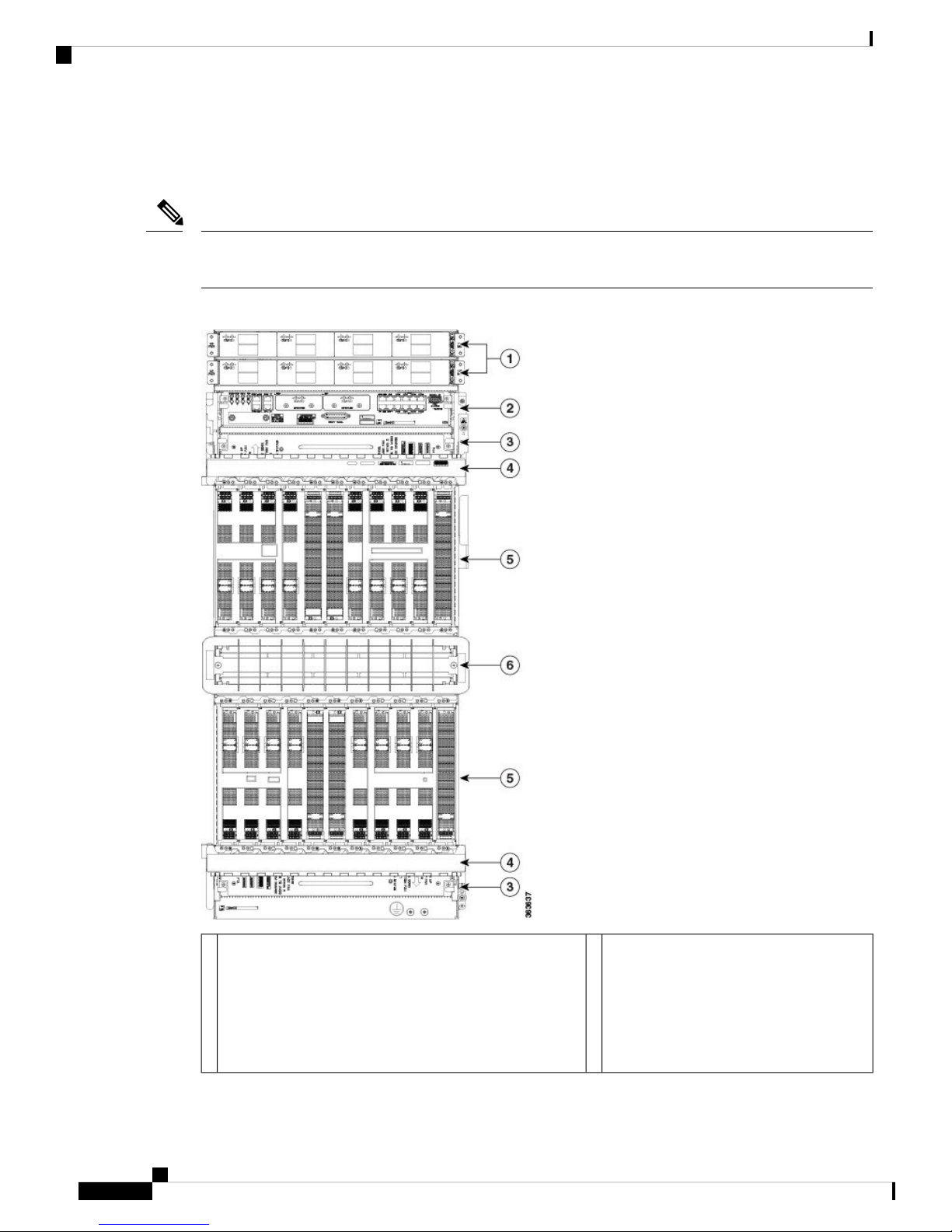
Figure 1: Front View of the NCS 4016
Chassis Overview
1
• Power tray 0 (PS0) contain PS0-PM0, PS0-PM1,
PS0-PM2, and PS0-PM3 power modules.
• Power tray 1 (PS1) contain PS1-PM0, PS1-PM1,
PS1-PM2, and PS1-PM3 power modules.
Hardware Installation Guide for the Cisco NCS 4000 Series
2
Fiber management areas (2)4Power trays (2) , each containing four power modules:
Page 5

Chassis Overview
About the Cisco NCS 4016 and Cisco NCS 4009 Chassis
Card cages (2) each containing:
2
5External connection unit (ECU)
• Craft panel is attached on top of the ECU
• Air outlet is on the back
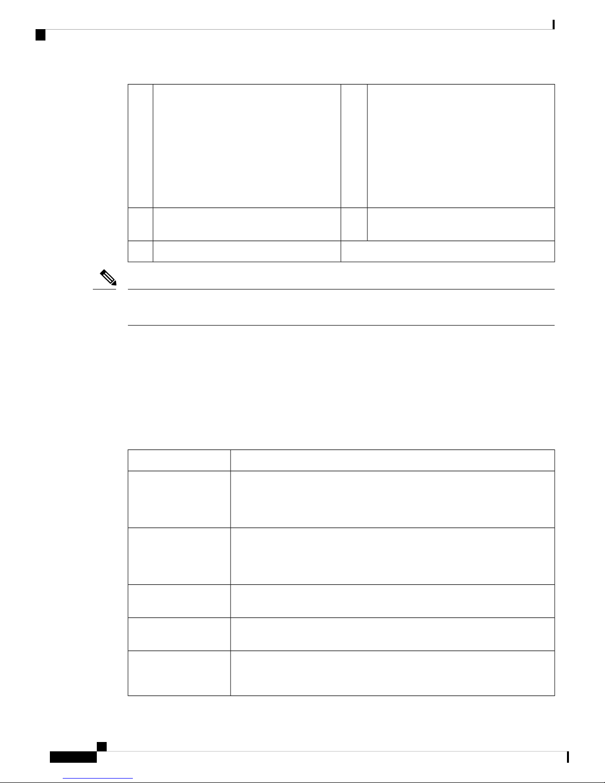
Figure 2: Front View of the Cisco NCS 4009
• Eight LC slots - LC0 to LC7; LC8 to
LC15
• Two FC slots - FC0 and FC1; FC2 and
FC3
• One RP slot - RP0 and RP1
Air inlet6Fan trays (2)3
Hardware Installation Guide for the Cisco NCS 4000 Series
3
Page 6
Chassis Components
Note
Chassis Overview
Card cage containing:
1
modules:
• Power tray 0 (PS0) contain PS0-PM0,
4Power trays (2) , each containing four power
• Nine LC slots - LC0 to LC8
• Two RP slots - RP0 and RP1
PS0-PM1, PS0-PM2, and PS0-PM3 power
modules.
• Power tray 1 (PS1) contain PS1-PM0,
PS1-PM1, PS1-PM2, and PS1-PM3 power
modules.
Four fabric card slots (FC0 to FC3) covered by
2
Panel/Air Outlet
5External Connection Unit (ECU /Craft
the inlet air filter
Fan tray3
There are two air outlets on the rear of the NCS 4016. One is at the top behind the ECU and one is below the
bottom fan tray. For NCS 4009, there is one air outlet on the top of the chassis, below the power tray.
For more details of the chassis, see datasheet at https://www.cisco.com/c/en/us/products/collateral/
optical-networking/network-convergence-system-4000-series/data_sheet_c78-729222.html.
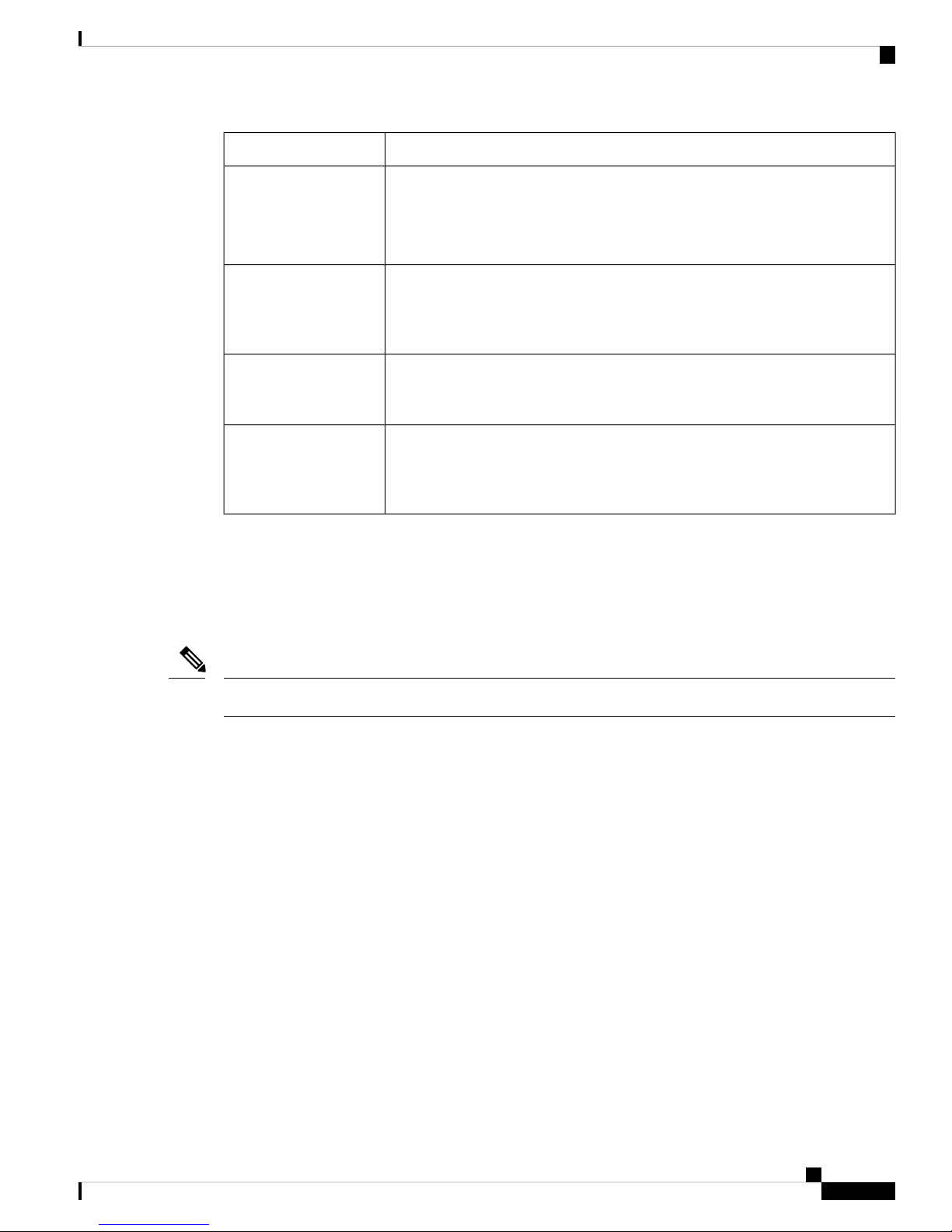
Chassis Components
This table lists the main components of the chassis.
Table 1: Main Components of the Chassis
Route Processor Cards
(RPs)
Fabric Cards (FCs)
Line Cards (LCs)
DescriptionComponent
These cards provide the intelligence of the system by functioning as the system
controller and providing route processing and chassis management. The RP cards
also monitor system alarms and control the system fans. The LEDs on the front
panel indicate active alarm conditions.
The FCs provide the switch fabric for the routing system and performs the
cross-connect function of the routing system, connecting every LC to each other.
The switch fabric receives ingress user data from one LC slot and performs the
switching necessary to route the data to the appropriate egress LC slot.
These cards provide the physical interfaces and optical connections for the user
data.
External Connection
Unit (ECU)
Craft Panel
Hardware Installation Guide for the Cisco NCS 4000 Series
4
The ECU provides all shelf electrical I/O connectivity to the active and standby
route-processor line cards. The ECU is located behind the craft panel.
The craft panel can install, configure, monitor, and troubleshoot the chassis
applications at the node and at the network level. The craft panel is located on top
of the ECU.
Page 7
Chassis Overview
Safety Guidelines
DescriptionComponent
Fan Trays
Air Filter
Power Trays
Fiber Management Trays
Safety Guidelines
Before you perform any chassis installation procedures, review the safety guidelines in this section to avoid
injuring yourself or damaging the equipment.
The fan tray cools the card rack. A fan tray contains six axial fans. The fans pull
cooling air through the chassis from the front to rear.
NCS 4016 has two fan trays that are inserted into the front of the chassis at the
top and bottom. NCS 4009 has only the top fan tray behind the craft panel.
NCS 4016 has two independent air filters, located in the middle of the chassis
behind the plastic inlet grill. One is dedicated to the top card rack and the other to
the bottom card rack. In NCS 4009, there is only one air filter and it is located
above the slots of the fabric cards.
Two power trays, AC and DC, provide redundant power to the chassis. A power
tray is a field serviceable unit (FSU). A mixture of AC and DC power is not
supported in the chassis.
The chassis has fiber management features for the front side only. For the NCS
4016, the horizontal fiber management brackets are located above and below the
card cages. For NCS 4009, the horizontal fiber management bracket is located
above the card cage.
Note
Power off the system before removing or installing a power tray.
The following guidelines are for your safety and to protect equipment. The guidelines do not include all
hazards. Be alert.
• Never attempt to lift an object that might be too heavy for you to lift by yourself.
• Keep the work area clear and dust-free during and after installation. Do not allow dirt or debris to enter
into any laser-based components.
• Keep tools and chassis components away from walk areas.
• Do not wear loose clothing, jewelry, and other items that could get caught in the chassis while working
with the chassis and its components.
• Use Cisco equipment in accordance with its specifications and product-usage instructions.
• Do not work alone if potentially hazardous conditions exist.
• Make sure that your installation follows national and local electrical codes: in the United States, National
Fire Protection Association (NFPA) 70, United States National Electrical Code; in Canada, Canadian
Electrical Code, part I, CSA C22.1; in other countries, International Electrotechnical Commission (IEC)
60364, part 1 through part 7.
• Connect only a DC power source that follows the safety extra-low voltage (SELV) requirements in
UL/CSA/IEC/EN 60950-1 and AS/NZS 60590 to the DC input power system.
• Make sure that you have a readily accessible two-poled disconnect device incorporated in the fixed
configuration wiring of a DC input power system.
Hardware Installation Guide for the Cisco NCS 4000 Series
5
Page 8
Preventing Electrostatic Discharge
• Make sure that you provide short-circuit (overcurrent) protection as part of the building installation.
Preventing Electrostatic Discharge
Electrostatic discharge (ESD) damage, which can occur when electronic cards or components are improperly
handled, results in complete or intermittent failures. We recommend use of an ESD-preventive wrist strap
whenever you handle network equipment or one of its components. For guidelines to prevent ESD damage,
see Preventing Electrostatic Discharge, on page 29
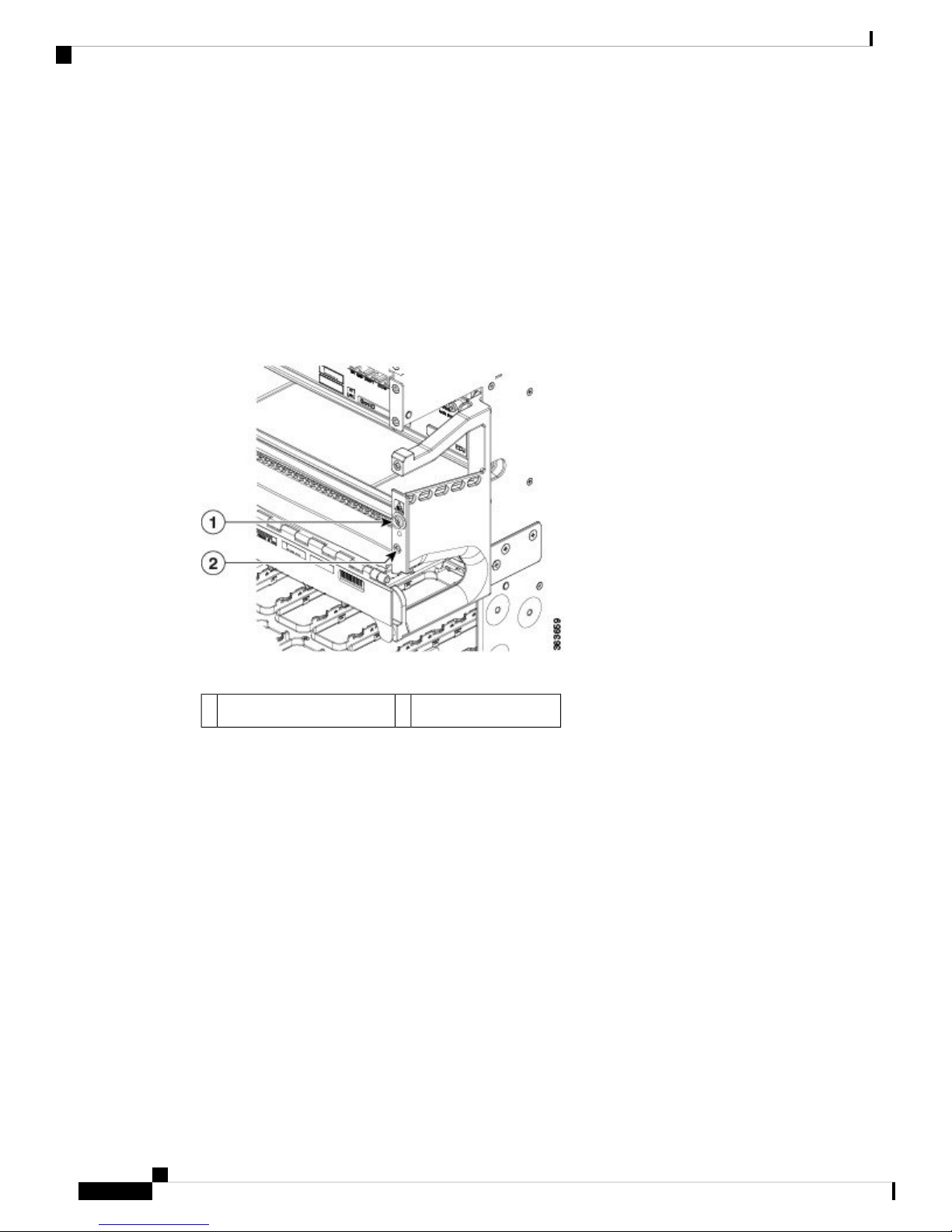
Two ESD jacks are provided, one at the top of the chassis and one at the bottom of the chassis.
Figure 3: ESD Jacks—Top of Chassis
Chassis Overview
Top ANSI jacket point2Top ETSI connection point1
Hardware Installation Guide for the Cisco NCS 4000 Series
6
Page 9

CHAPTER 2
Mounting the Chassis
This chapter describes how to secure the chassis in the rack.
Note
Unless otherwise specified, “chassis” refers to both Cisco NCS 4016 chassis and Cisco NCS 4009 chassis.
Note
To install two Cisco NCS 4016 chassis in a single rack, you will need to have a minimum vertical opening
of 48 RU. If you are using the DC Power Front Connection Adapter, only one chassis will fit into the rack.
• Preparing the Rack for Chassis Installation, on page 7
• Preparing to Mount the Chassis in a Rack, on page 9
• Mounting the Chassis into a Rack, on page 24
Preparing the Rack for Chassis Installation
Install the chassis into one of the following standard racks:
• ANSI 19-inch or 23-inch (2- or 4-post)
• ETSI
Note
For the ANSI 19-inch rack, the minimum front opening must be 17.72 inches (450 mm) to allow for chassis
insertion.
If you are installing a single chassis in a rack, the chassis must go in the middle or bottom portion of the rack
or follow your company chassis mounting practices.
Note
At the bottom of the rack, keep 1 rack unit free to allow for removal of the bottom fan tray.
Hardware Installation Guide for the Cisco NCS 4000 Series
7
Page 10
Preparing the Rack for Chassis Installation
To bolt the rack to the floor, a floor bolt kit (also called an anchor embedment kit ) is required. For information
on bolting the rack to the floor, consult a company that specializes in floor mounting kits. Make sure that floor
mounting bolts are accessible, especially if annual re-torquing of bolts is required.
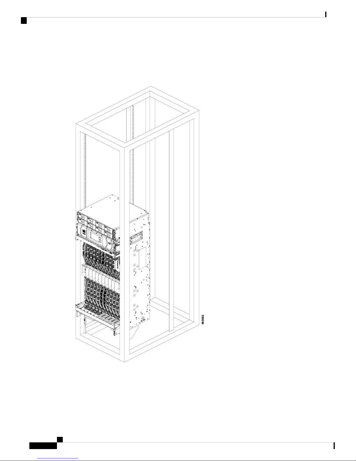
Figure 4: Single NCS 4016 Chassis Mounted in Rack
Mounting the Chassis
Before you move the chassis or mount the chassis into the rack, we recommend that you do the following:
Hardware Installation Guide for the Cisco NCS 4000 Series
8
Page 11
Mounting the Chassis
Step 1 Place the rack where you plan to install the chassis.
Step 2 Secure the rack to the floor.
Preparing to Mount the Chassis in a Rack
Procedure
Warning
The chassis should be mounted on a rack that is permanently affixed to the building. Statement
1049
Preparing to Mount the Chassis in a Rack
Before you mount the chassis into a rack, it is critical that the installation site be prepared properly to handle
the chassis weight, power requirements, cooling needs, and other requirements.
You should review the rack specifications from the manufacturer to determine whether the racks you have
are appropriate to handle the weight of the chassis.
Caution
Installing the Mounting Brackets
To avoid tipping the chassis and possible injury when installing it, take care to properly position the chassis
in the rack when you are mounting it.
Before mounting the chassis in the rack, perform the following steps:
This section explains how to install the top and bottom mounting brackets for the specific type of rack you
are using.
• For 2-post ANSI racks, the brackets are installed in the middle position.
• For 4-post ANSI racks and ETSI cabinets, the brackets are installed in the front position.
Prerequisites
Make sure that you have the correct type of mounting brackets to suit your rack type. There are three different
types of mounting brackets for the three types of racks (ANSI 19-inch or 23-inch or ETSI).
Tools and Equipment
• Number 2 Phillips screwdriver
• Cisco NCS 4009 installation kit (NCS4009-INST-KIT=)
• Cisco NCS 4016 installation kit (NCS4K-INST-KIT=)
Installing the Mounting Brackets
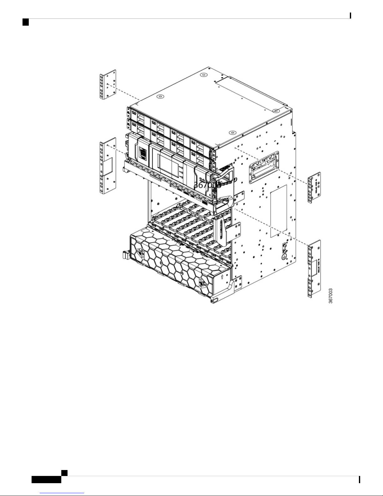
To attach the mounting brackets, simply fix each bracket onto the chassis using screws as shown in the figure,
below. Tighten the screws to a torque value of 11.5 in-lb (1.3 N-m).
Hardware Installation Guide for the Cisco NCS 4000 Series
9
Page 12
Installing the Mounting Brackets
Figure 5: Attaching Chassis Mounting Brackets in NCS 4009
Mounting the Chassis
Hardware Installation Guide for the Cisco NCS 4000 Series
10
Page 13
Mounting the Chassis
Installing the Mounting Brackets
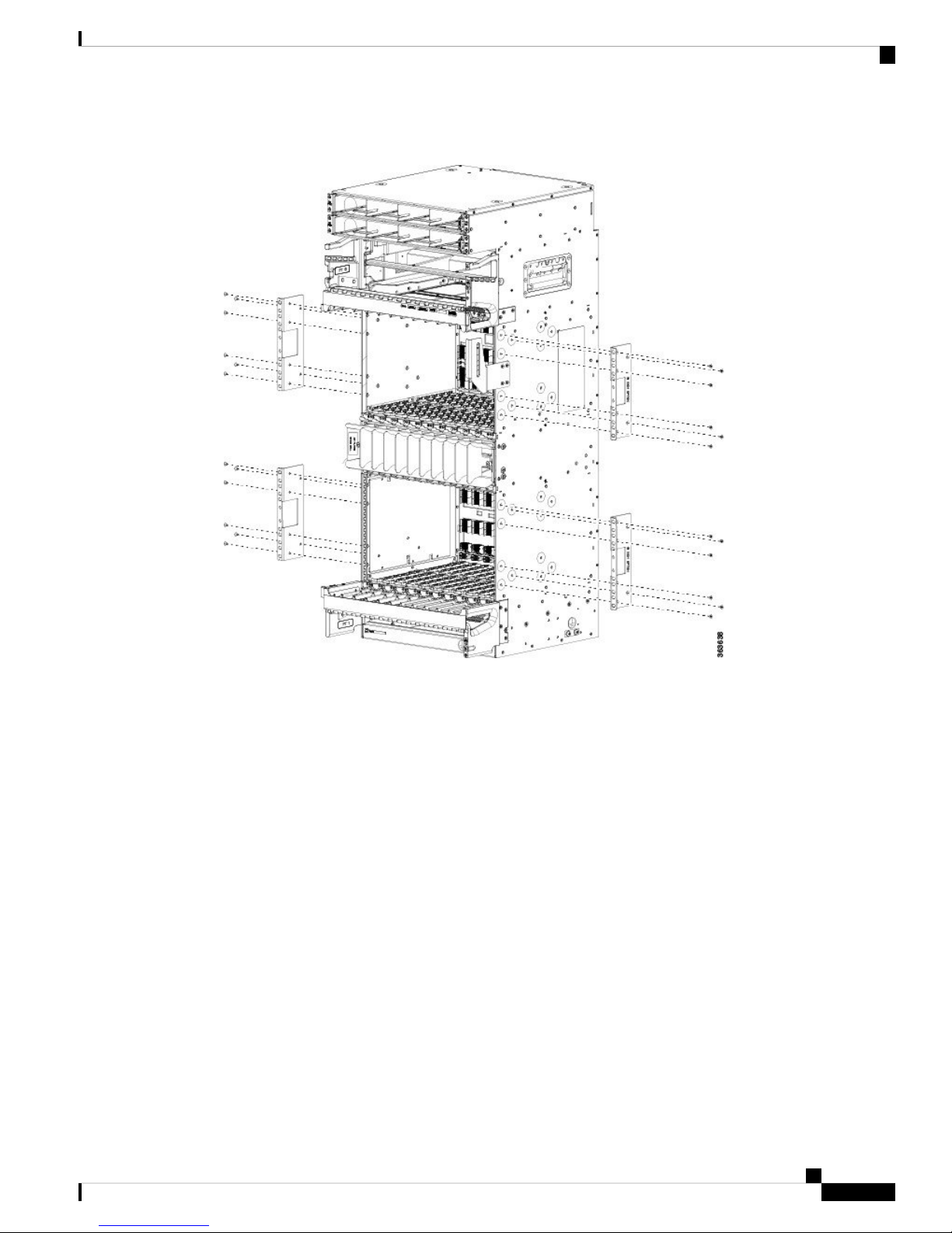
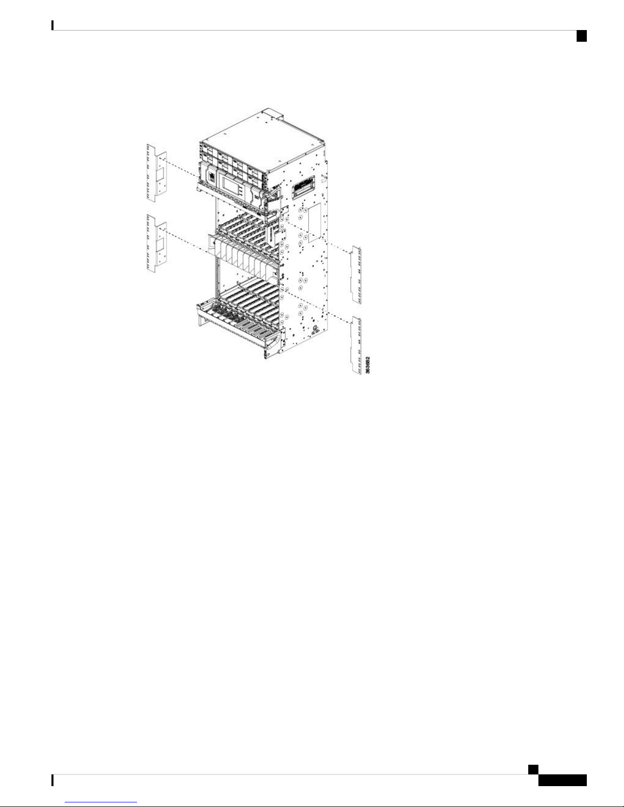
Figure 6: Attaching Chassis Mounting Brackets in NCS 4016
Various types of bracket installation are shown in these illustrations:
Hardware Installation Guide for the Cisco NCS 4000 Series
11
Page 14
Installing the Mounting Brackets
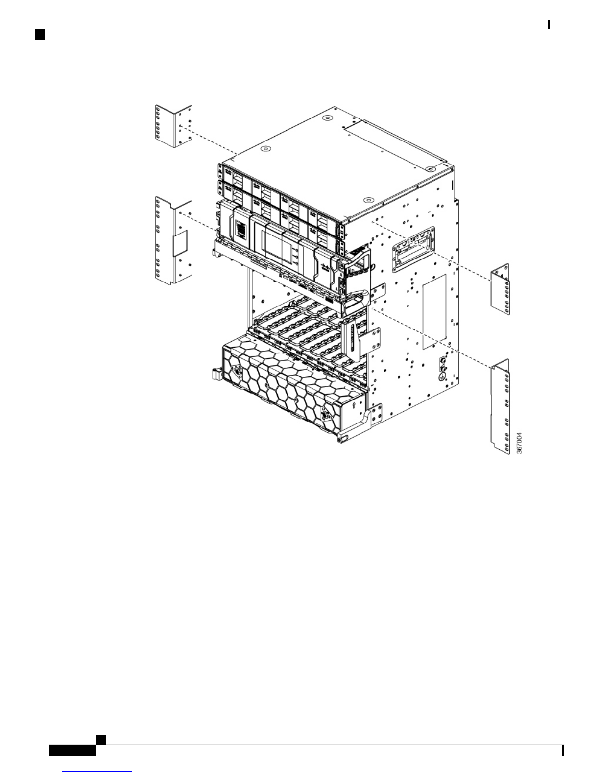
Figure 7: Attaching ANSI 19-Inch Brackets to Front (4-Post Rack) or Middle (2-Post Rack) in NCS 4009
Mounting the Chassis
Hardware Installation Guide for the Cisco NCS 4000 Series
12
Page 15
Mounting the Chassis
Installing the Mounting Brackets
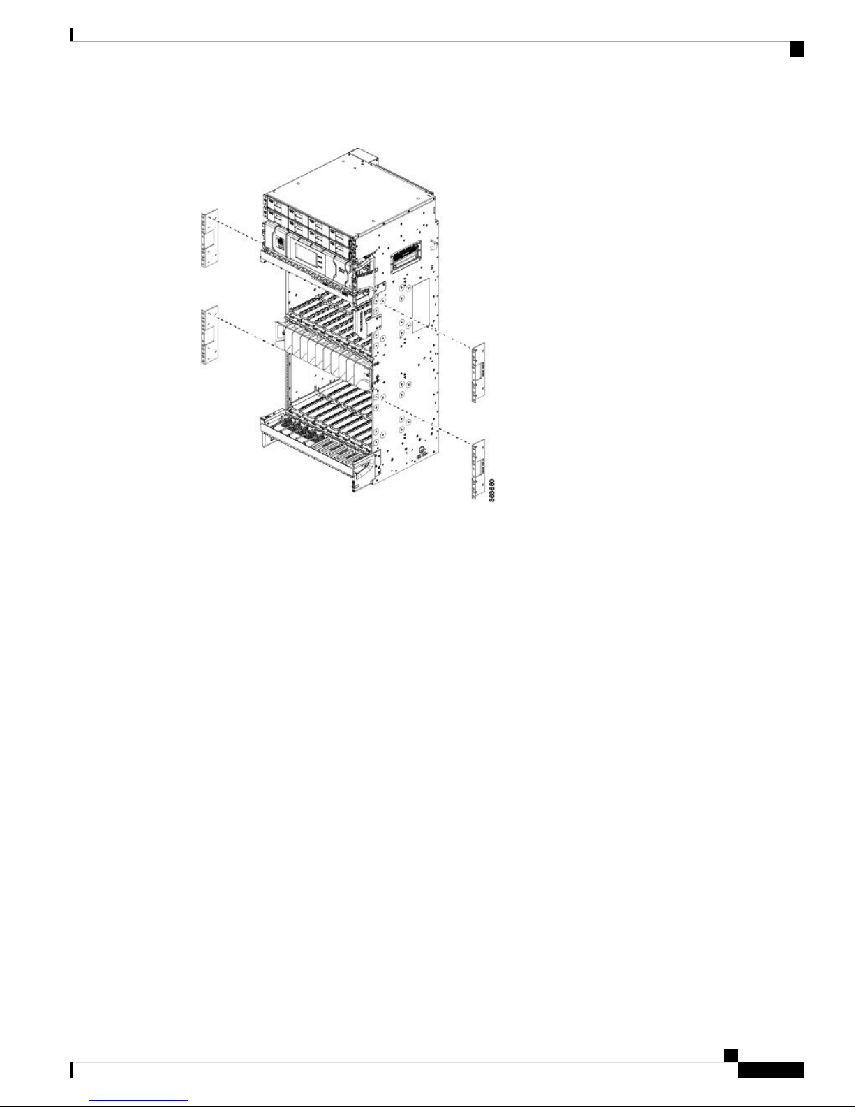
Figure 8: Attaching ANSI 19-Inch Brackets to Front (4-Post Rack) or Middle (2-Post Rack) in NCS 4016
Hardware Installation Guide for the Cisco NCS 4000 Series
13
Page 16
Installing the Mounting Brackets
Figure 9: Attaching ANSI 23-Inch Brackets to Front (4-Post Rack) or Middle (2-Post Rack) in NCS 4009
Mounting the Chassis
Hardware Installation Guide for the Cisco NCS 4000 Series
14
Page 17
Mounting the Chassis
Installing the Mounting Brackets
Figure 10: Attaching ANSI 23-Inch Brackets to Front (4-Post Rack) or Middle (2-Post Rack) in NCS 4016
Hardware Installation Guide for the Cisco NCS 4000 Series
15
Page 18

Installing the Mounting Brackets
Figure 11: Attaching ETSI Brackets to Front in NCS 4009
Mounting the Chassis
Figure 12: Attaching ETSI Brackets to Front in NCS 4016
Hardware Installation Guide for the Cisco NCS 4000 Series
16
Page 19

Mounting the Chassis
Installing the Aid Brackets
This section explains how to install the aid brackets onto the rack. The aid brackets hold the weight of the
chassis while you secure it in the rack.
Prerequisites
Identify the position of the chassis inside the rack to define the aid brackets position.
Tools and Equipment
• Number 2 Phillips screwdriver
• Cisco NCS 4016 installation kit (NCS4K-INST-KIT=)
• Cisco NCS 4009 installation kit (NCS4009-INST-KIT=)
Steps
Procedure
Installing the Aid Brackets
Step 1 Attach the aid brackets to the rack below where the chassis will sit. Tighten the two screws to firmly attach
the brackets to the rack.
Hardware Installation Guide for the Cisco NCS 4000 Series
17
Page 20
Installing the Aid Brackets
Figure 13: Attaching Aid Brackets to the Rack for NCS 4016
Mounting the Chassis
Step 2 Once the chassis has been installed, remove the aid brackets. Loosen the two screws from the aid brackets
and take off the rack.
Tip
Keep the aid brackets in case of future chassis relocation.
What to do next
To accommodate equipment racks with different mounting hole patterns, the aid brackets have groups of
screw holes on either side.
The mounting holes in the aid brackets are spaced so that one mounting hole in each hole group aligns with
a corresponding hole in the equipment rack. By using the corresponding mounting hole (in the same hole
group) on the opposite side of the rack, you can keep both the aid brackets leveled.
Hardware Installation Guide for the Cisco NCS 4000 Series
18
Page 21

Mounting the Chassis
Removing and Replacing the Chassis Door
Caution
When you are installing the chassis in a rack, leave the filler cards in place to provide the chassis with enough
support to keep it square during the procedure.
Caution
Because of the chassis size and weight, it is unsafe to lift the chassis without mechanical assistance.
Removing and Replacing the Chassis Door
Before installing the chassis in a rack, remove the front door of the chassis to ensure that the door is not
damaged in any way.
Tools and Equipment
• ESD-preventive wrist strap
• Number 2 Phillips screwdriver, medium and small slot-head screwdrivers
• NCS 4016 front door: (Cisco PID NCS4016-DOOR=)
• NCS 4009 front door: (Cisco PID NCS4009-DOOR=)
Steps
Procedure
Step 1 Turn the knob to unlock the door.
Step 2 Open the door.
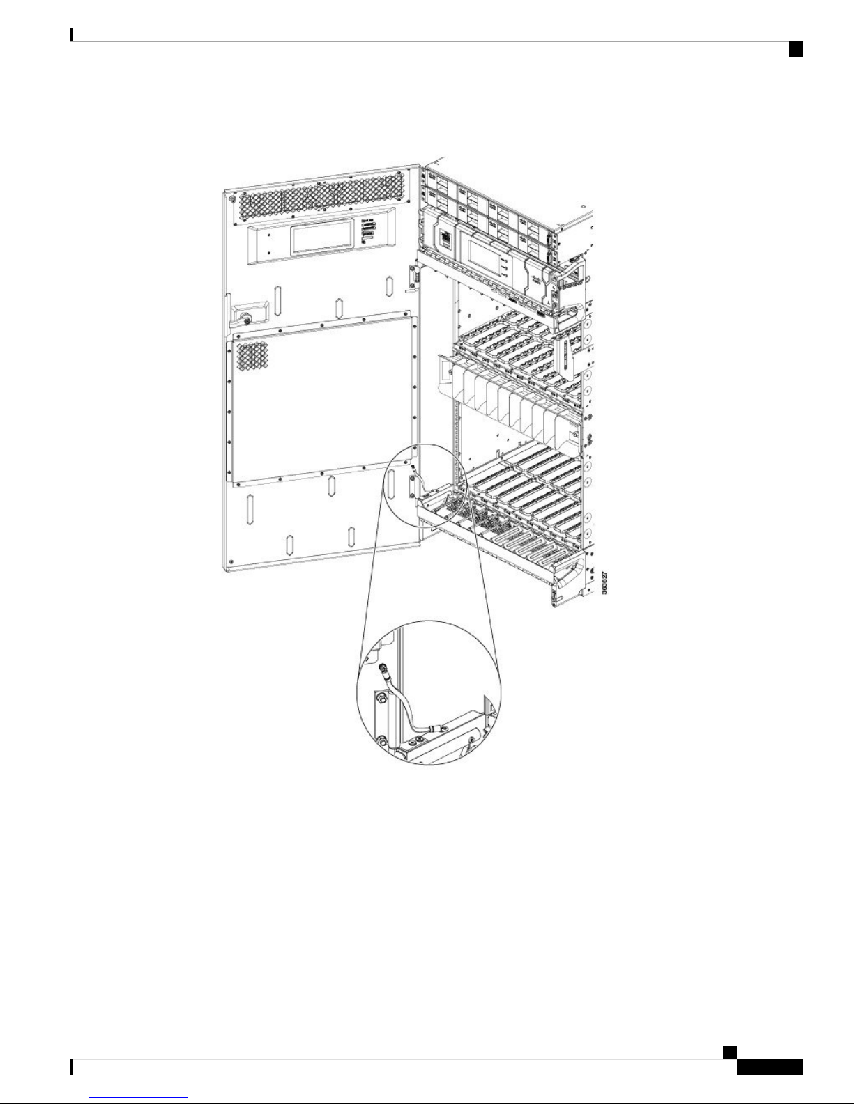
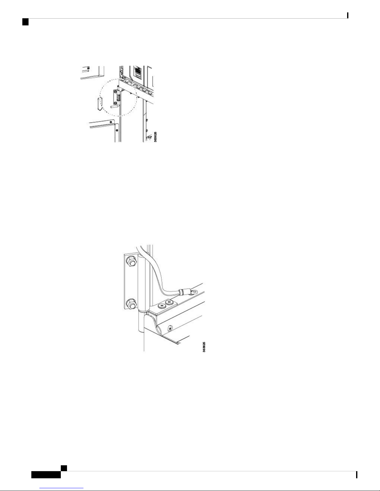
Step 3 Loosen the screw to disconnect the ground cable.
Hardware Installation Guide for the Cisco NCS 4000 Series
19
Page 22
Removing and Replacing the Chassis Door
Figure 14: Disconnecting the Ground Cable in NCS 4009
Mounting the Chassis
Hardware Installation Guide for the Cisco NCS 4000 Series
20
Page 23
Mounting the Chassis
Removing and Replacing the Chassis Door
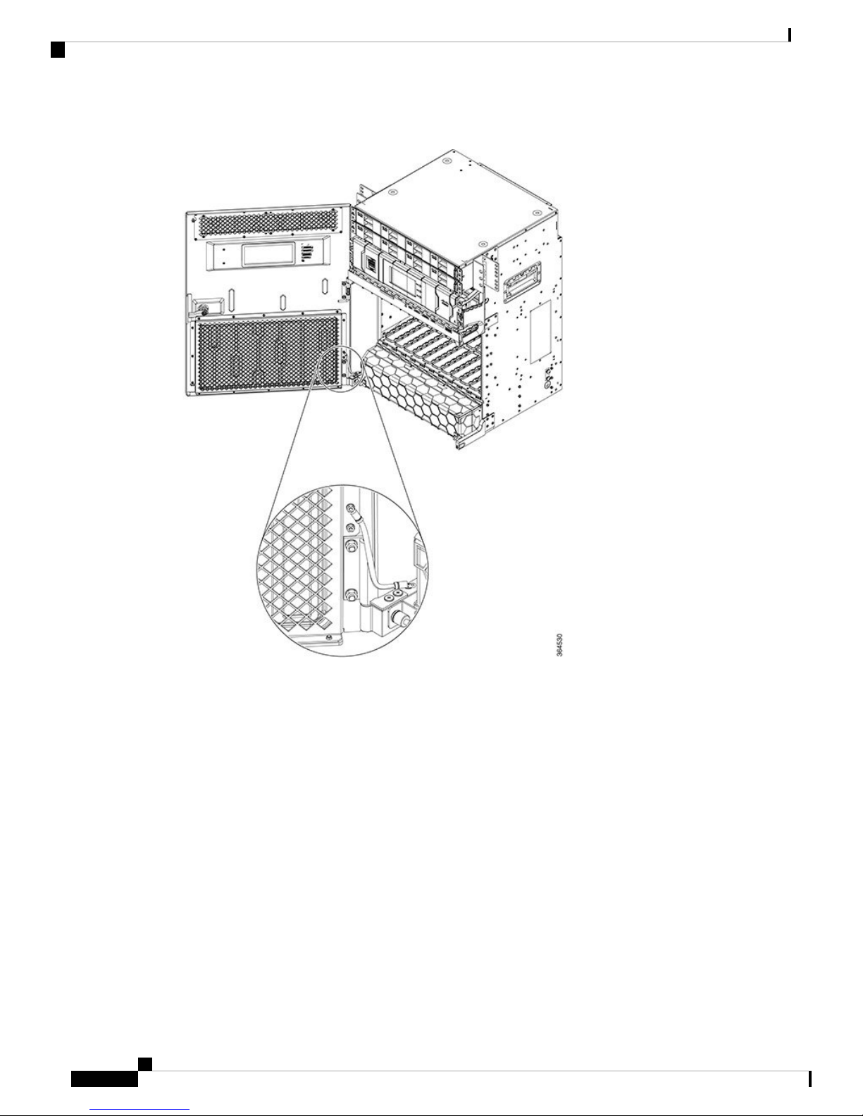
Figure 15: Disconnecting the Ground Cable in NCS 4016
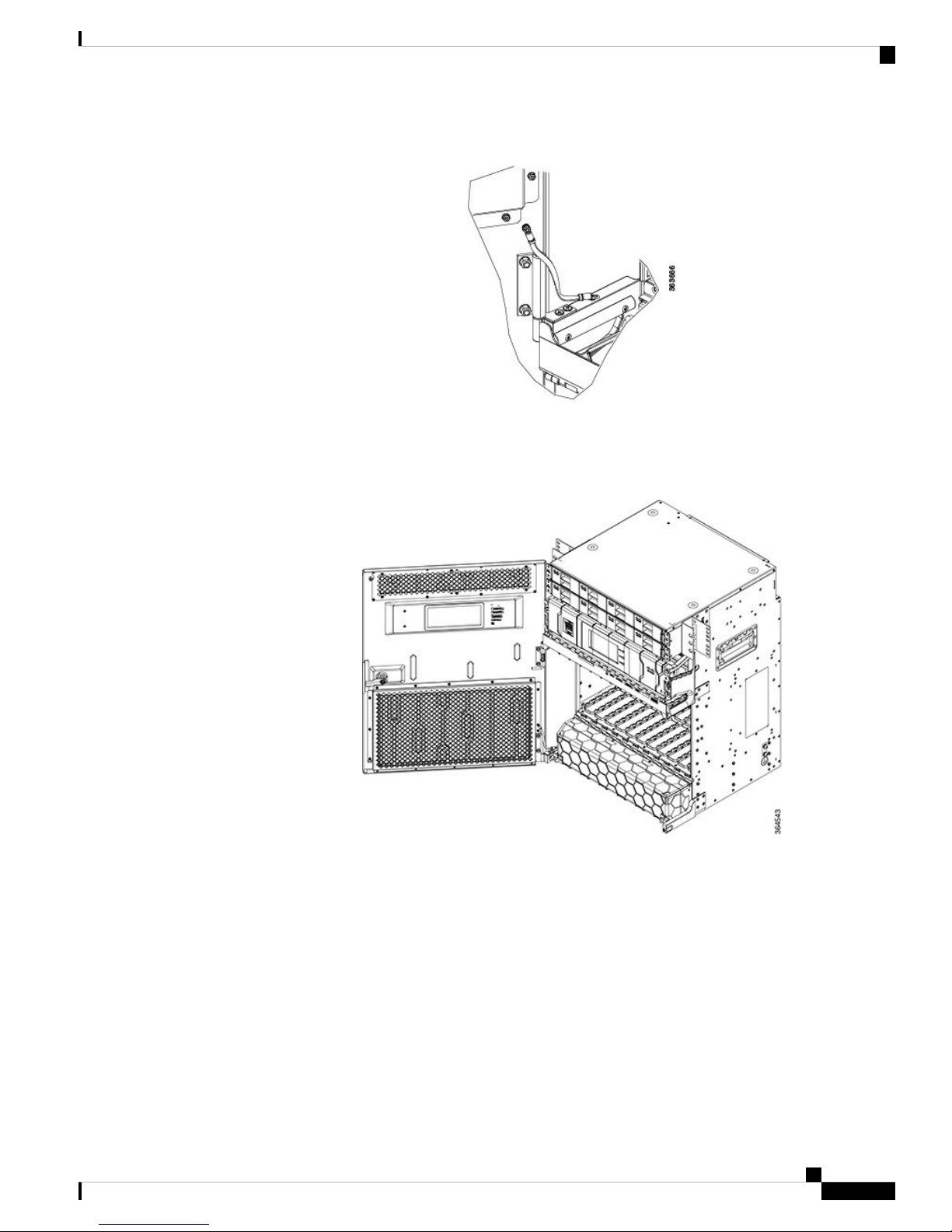
Step 4 Move down the pin to release the door from the chassis hinge.
Hardware Installation Guide for the Cisco NCS 4000 Series
21
Page 24
Removing and Replacing the Chassis Door
Figure 16: Pin to Release Door from Hinge
Step 5 Move up the door to release the bottom hinge pin.
Figure 17: Releasing the Bottom Hinge Pin
Mounting the Chassis
Step 6 To replace the front door after the chassis is mounted on the rack:
a) Remove the screw and washer from the chassis fixing point.
Hardware Installation Guide for the Cisco NCS 4000 Series
22
Page 25
Mounting the Chassis
Removing and Replacing the Chassis Door
Figure 18: Installing the Door Ground Strap Retrofit Kit
b) Feed the screw through the ground cable ring lug, through the washer, and then into the machined block.
c) Using a Phillips screwdriver, insert and tighten the screws to a torque value of 11.5 in-lb (1.3 N-m).
Figure 19: NCS 4009 with Door Ground Strap Retrofit Kit Installed (ANSI)
Hardware Installation Guide for the Cisco NCS 4000 Series
23
Page 26

Mounting the Chassis into a Rack
Figure 20: NCS 4016 with Door Ground Strap Retrofit Kit Installed (ANSI)
Mounting the Chassis
d) Swing the door closed and turn the knob to lock.
Mounting the Chassis into a Rack
This section describes how to mount the chassis into a rack.
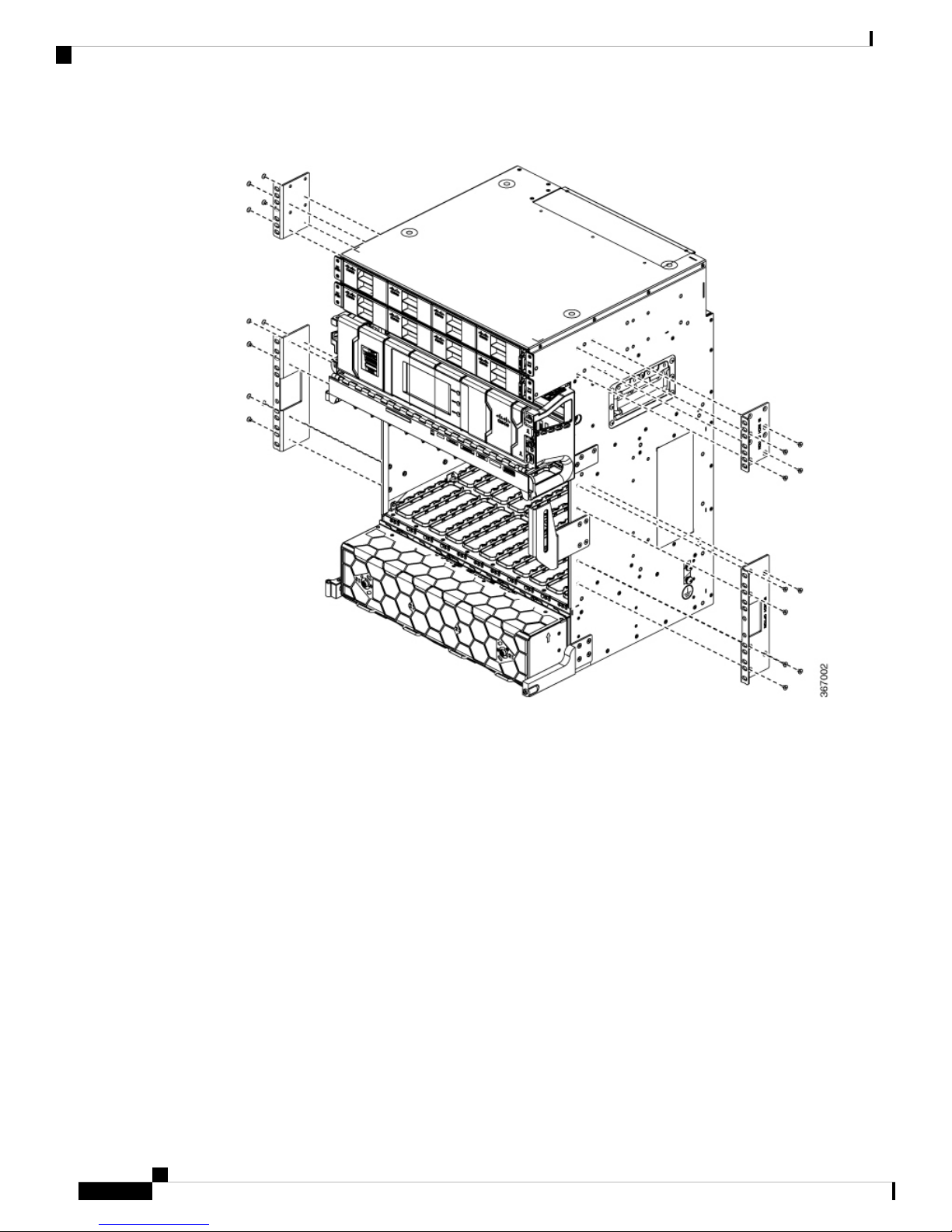
The figure below, shows the chassis mounting hardware ready for rack mounting.
Hardware Installation Guide for the Cisco NCS 4000 Series
24
Page 27

Mounting the Chassis
Mounting the Chassis into a Rack
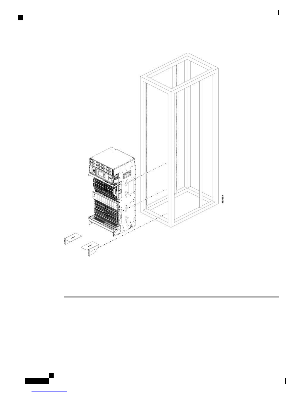
Figure 21: Chassis Mounting Hardware Ready for Rack Mounting
Prerequisites
• Make sure that the rack is level and bolted to the floor.
• Make sure that the mounting brackets are installed on the chassis.
• Make sure that the aid brackets are installed on the rack.
Tools and Equipment
• Number 2 Phillips screwdriver
• Mechanical lifting device, such as a scissor lift or other suitable lifting device
• NCS 4016 installation kit, shipped with the chassis, contains installation aid brackets and screws (Cisco
PID NCS4K-INST-KIT=)
Hardware Installation Guide for the Cisco NCS 4000 Series
25
Page 28

Mounting the Chassis into a Rack
• NCS 4009 installation kit, shipped with the chassis, contains installation aid brackets and screws (Cisco
PID NCS4009-INST-KIT=)
Steps
To mount the chassis in the rack, follow these steps:
Procedure
Step 1 With the chassis on the lift, align the chassis with the rack.
Step 2 Using your mechanical lift, raise the chassis to the height of the rack’s installation aid brackets.
As an example of a suitable lifting device, the figure below, shows a scissor lift raising the chassis.
Mounting the Chassis
Note
Figure 22: Example—Using a Scissor Lift to Position the Chassis in the Rack
Take extra care when aligning the bottom of the chassis with the installation aid brackets.
Step 3 Move the chassis. With at least two people, stand in front of the chassis and carefully push the chassis into
the rack.
Step 4 Move the lift aid away from the front of the chassis.
Step 5 Push carefully until the mounting brackets contact the rack mounting bracket with the vertical rack posts.
Someone should be in the rear guiding the chassis into the rack.
Step 6 Insert and partially tighten the screws to attach the chassis mounting brackets to the rack mounting brackets.
Hardware Installation Guide for the Cisco NCS 4000 Series
26
Page 29

Mounting the Chassis
Mounting the Chassis into a Rack
Figure 23: Chassis Mounting Holes
Hardware Installation Guide for the Cisco NCS 4000 Series
27
Page 30

Mounting the Chassis into a Rack
Mounting the Chassis
Note
To accommodate equipment racks with different mounting-hole patterns, the chassis mounting
brackets have groups of screw holes on either side. The mounting holes in these rails are spaced so
that one hole in each hole group aligns with a hole in the equipment rack or the optional center-mount
bracket. Use the corresponding mounting hole (in the same hole group) on the opposite side of the
chassis to level the chassis in the rack.
Step 7 Use the screwdriver to fully tighten the screws. Tighten the screws to a torque value of 22 in-lb (2.5 N-m).
Hardware Installation Guide for the Cisco NCS 4000 Series
28
Page 31

CHAPTER 3
Installing Route Processor Cards, Fabric Cards,
and Line Cards
This chapter provides instructions on how to install route processor (RP) cards, fabric cards (FCs), line cards
(LCs) and their associated components in the chassis.
Note
Unless otherwise specified, "chassis" refers to both Cisco NCS 4016 chassis and Cisco NCS 4009 chassis.
• Preventing Electrostatic Discharge, on page 29
• Guidelines for Installing and Removing a Card, on page 30
• Installing and Removing a Filler Card, on page 30
• About RP Cards, on page 32
• About Fabric Cards, on page 33
• About Line Cards, on page 34
• Installing a Route Processor, Fabric Card, or Line Card , on page 35
• Troubleshooting the RP, FC, or LC Card, on page 46
• Connecting Line Card Network Interface Cables, on page 47
• Connecting Cables to the RP, on page 49
Preventing Electrostatic Discharge
Electrostatic discharge (ESD) damage, which can occur when electronic cards or components are improperly
handled, results in complete or intermittent failures. We recommend use of an ESD-preventive wrist strap
whenever you handle network equipment or one of its components.
• Always use an ESD-preventive wrist or ankle strap, and ensure that it makes good skin contact. Connect
the equipment end of the connection cord to an ESD jack or a bare metal surface on the chassis (ensure
that the chassis is grounded).
• Handle a card by its ejector levers, when applicable, or its metal carrier only; avoid touching the board
or connector pins .
• Place a removed card board-side-up on an antistatic surface or in a static-shielding bag. If you plan to
return the component to the factory, immediately place it in a static-shielding bag.
• Avoid contact between a card and clothing. The wrist strap protects the board from only ESD voltage
on the body; ESD voltage on clothing can still cause damage.
Hardware Installation Guide for the Cisco NCS 4000 Series
29
Page 32

Installing Route Processor Cards, Fabric Cards, and Line Cards
Guidelines for Installing and Removing a Card
• Be careful not to lay any tools on the aluminum honeycomb panel, or insert your fingers into the panel.
Guidelines for Installing and Removing a Card
• Online (in-service) insertion and removal (OIR) is supported, enabling you to remove and install cards
while the chassis is operating. OIR is seamless to users on the network, maintains all routing information,
and ensures session preservation. You do not need to notify the software or reset the power. You have
the option of using the Cisco IOS XR shutdown command before removing a card.
Note
OIR removes power to a specific slot before the card is replaced. The power remains on for all other card
slots.
• The different cards in the chassis are all attached to the chassis itself using a pair of ejector levers and
captive screws. The two ejector levers release the card from its backplane connector. The exact locations
of the ejector levers and captive screws can vary slightly from card to card, but they are generally in the
same locations: on the upper and bottom ends of the faceplate.
• When you remove a card, press the OIR buttons before using the ejector levers to ensure that the connector
pins disconnect from the backplane in the sequence expected by the chassis.
• The correct card orientation is shown by the eject symbol on the OIR buttons. The symbol must be
oriented upward for cards in NCS 4009, or in the top row for NCS 4016, and downward for cards in the
bottom row in the NCS 4016 chassis.
• Every FC, LC, and RP card has a key mounted on the board that matches a corresponding slot on the
chassis side (top of each card slot). This key-slot mechanism prevents a card from being inserted into
the wrong, non-matching card slot. It also prevents a card from being inserted upside down. When a card
is inserted into the wrong card slot or upside down, the key will get blocked against the chassis card
guide and not slide though the slot. When the key gets blocked, remove the card and find the correct card
slot.
• Any unused card slots that are uncovered would allow air used for chassis cooling to escape. Therefore,
to ensure proper air flow and maintain system EMC and safety compliance, any unused LC slots must
contain filler cards, and all FC and RP cards must remain installed in their card slots.
• Fully insert all FC and RP cards into the chassis before tightening their captive screws.
Caution
The chassis may indicate a hardware failure if you do not follow proper procedures. Remove or install only
one card at a time. Allow at least 30 seconds for the chassis to complete its tasks before removing or installing
another card.
Installing and Removing a Filler Card
Caution
30
To ensure thermal regulation in the chassis, keep filler cards installed in all slots that do not have an LC.
This section contains the following procedures:
Hardware Installation Guide for the Cisco NCS 4000 Series
Page 33

Installing Route Processor Cards, Fabric Cards, and Line Cards
Installing a Filler Card
This section describes how to install a filler card in the chassis.
Prerequisites
Before performing this task, open the front door, if installed, and ensure that the slot in which you are about
to install the filler card is empty.
Tools and Equipment
• Number-2 Phillips screwdriver
• LC filler card (Cisco PID NCS4K-BLANK)
Steps
The following steps describe how to install a filler card.
Figure 24: LC Slot Filler Card
Installing a Filler Card
Procedure
Step 1 Determine the correct orientation of the filler card:
• In NCS 4016, if you are installing the card in the top rack, the arrow should be pointing up. If you are
installing the card in the bottom rack, the arrow should be pointing down.
• In NCS 4009, the arrow on the faceplate should be pointing up.
Hardware Installation Guide for the Cisco NCS 4000 Series
31
Page 34

Removing a Filler Card
Step 2 Use both hands while inserting a filler card. Use one hand on the faceplate and the other hand along the base
of the filler card to guide it into the slot.
Step 3 Slide the filler card into the chassis until the captive screw plates are flush with the chassis.
Step 4 Partially tighten the two captive screws on the front panel of the filler card (either by hand or with the number-2
Phillips screwdriver or number-2 common [flat-head] screwdriver) to make sure that they are both engaged.
Step 5 Use the number-2 Phillips screwdriver to fully tighten the captive screws using 10.60 pound/force (lbf) inch
(1.20 Nm torque) to seat the filler card firmly in the slot.
Removing a Filler Card
This section describes how to remove a filler card from the chassis.
Prerequisites
Before performing this task, open the front door, if installed.
Tools and Equipment
Installing Route Processor Cards, Fabric Cards, and Line Cards
• Number-2 Phillips screwdriver
Steps
The following steps describe how to remove a filler card.
Procedure
Step 1 Identify the filler card to be removed from the card cage. Use the number-2 Phillips screwdriver, and turn the
two captive screws on the front panel of the card counterclockwise to loosen the card from the slot.
Step 2 Grasp the filler card handle with one hand and gently pull it halfway from the slot.
Step 3 Place one hand under the filler card to guide it.
Step 4 Holding the filler card underneath and by the handle, pull it from the slot, and set it carefully aside.
About RP Cards
The chassis supports two route processors (RPs) that are identical. These cards provide the intelligence of the
system by functioning as the shelf controllers for DWDM or OTN applications and by providing route
processing and chassis management. The RP cards also monitor system alarms and control the system fans.
LEDs on the front panel indicate active alarm conditions.
Two RPs per chassis are required for a redundant system. RP cards are inserted into the two dedicated slots
(RP0 and RP1) in the chassis. The RP cards are hot-swappable.
Hardware Installation Guide for the Cisco NCS 4000 Series
32
Page 35

Installing Route Processor Cards, Fabric Cards, and Line Cards
About Fabric Cards
The chassis supports four fabric cards (FCs), which are agnostic cross-connects based on a flexible cell
switching architecture used in a Clos configuration. FCs are called agnostic because they will switch a cell
with no knowledge of whether they belong to OTN switching or Ethernet switching. Each fabric card in NCS
4016 hosts three fabric devices, which are equally distributed across the 16 line cards. whereas in NCS 4009,
the fabric card hosts a fabric device.
FCs provide the switch fabric for the routing system and perform the cross-connect function of the routing
system, connecting every LC to each other. The switch fabric receives ingress user data from one LC slot and
performs the switching necessary to route the data to the appropriate egress LC slot.
The chassis supports the 200G and 400G fabric cards. The 400G fabric card enables 400G traffic using the
400G line card. The datapath link speed of 400G FC-LC is twice that of the 200G FC-LC. The 200G and the
400G fabric cards support a single chassis only in NCS 4009.
About Fabric Cards
Compatible with 400G LCCompatible with 200G LCFC PIDChassis
NoYesNCS4009-FC-S (200G)NCS 4009
Caution
YesYesNCS4009-FC2-S (400G)
NCS4009-FC2F-S (400G)
YesNCS4016-FC-M (200G)NCS 4016
An Auxiliary Fan Tray (Cisco PID NCS4009-FAN-FC) is attached to the NCS4009-FC2F-S fabric card in
the front. The Auxiliary Fan Tray (AFT) and the fan tray present in the front of the chassis (behind the craft
panel), provide cooling for the chassis components.
The four NCS4009-FC2F-S fabric cards and the four AFTs should be present in the chassis at all times except
during the replacement of the FC or AFT.
The AFT remains attached to the fabric card at all times. The only time when the AFT can be detached from
the fabric card is when either the fabric card or the AFT needs to be replaced. Power is supplied to the AFT
through the NCS4009-FC2F-S fabric card.
No
YesYesNCS4016-FC2-M (400G)
Hardware Installation Guide for the Cisco NCS 4000 Series
33
Page 36

About Line Cards
Installing Route Processor Cards, Fabric Cards, and Line Cards
Figure 25: The NCS4009-FC2F-S Fabric Card with the AFT (NCS4009-FAN-FC)
NCS4009-FC2-S-KIT comprises the NCS4009-FC2F-S (fabric card) and the NCS4009-FAN-FC (AFT).
Twelve pluggable front panel connections allow a single-chassis system to migrate to a back-to-back or
multi-chassis configuration in NCS 4016.
About Line Cards
The chassis supports the following Optical Transport Network (OTN) line cards (LCs), packet LCs, and Dense
Wavelength-Division Multiplexing (DWDM) line cards. You can have a mix of OTN, packet, and DWDM
line cards in the same chassis.
• NCS4K-4H-OPW-QC2 Line Card - See datasheet at https://www.cisco.com/c/en/us/products/collateral/
optical-networking/network-convergence-system-4000-series/datasheet-c78-736495.html.
• 2-Port 100Gbps and 10-Port 10Gbps OTN and Packet (NCS4K-2H10T-OP-KS) Line Card - See datasheet
at https://www.cisco.com/c/en/us/products/collateral/optical-networking/
network-convergence-system-4000-series/datasheet-c78-736604.html.
• 24-Port Low-Rate OTN (NCS4K-24LR-O-S) Line Card - See datasheet at https://www.cisco.com/c/en/
us/products/collateral/optical-networking/network-convergence-system-4000-series/data_sheet_
c78-729398.html.
Sliding handle1
Captive screws2
• 20-Port 10GE OTN (NCS4K-20T-O-S) Line Card - See datasheet at https://www.cisco.com/c/en/us/
products/collateral/optical-networking/network-convergence-system-4000-series/data_sheet_
c78-729398.html.
Hardware Installation Guide for the Cisco NCS 4000 Series
34
Page 37

Installing Route Processor Cards, Fabric Cards, and Line Cards
Installing a Route Processor, Fabric Card, or Line Card
• 2-Port 100GE OTN (NCS4K-2H-O-K) Line Card - See datasheet at https://www.cisco.com/c/en/us/
products/collateral/optical-networking/network-convergence-system-4000-series/data_sheet_
c78-729398.html.
• 2-Port 100GE DWDM (NCS4K-2H-W) Line Card- See datasheet at https://www.cisco.com/c/en/us/
products/collateral/optical-networking/network-convergence-system-4000-series/data_sheet_
c78-729434.html
Installing a Route Processor, Fabric Card, or Line Card
Warning
Warning
Class 1 Laser Product. Statement 113
Because invisible radiation may be emitted from the aperture of the port when no fiber cable is connected,
avoid exposure to radiation and do not stare into open apertures. Statement 125
Prerequisites
Before performing this task, open the front door, if installed.
Tools and Equipment
• ESD-preventive wrist strap
• Number-2 Phillips screwdriver
• Route processor (RP): Cisco PID NCS4K-RP
• Fabric card (FC) in NCS 4016 : Cisco PID: NCS4016-FC-M or NCS4016-FC2-M
• Fabric card (FC) in NCS 4009: Cisco PID: NCS4009-FC-S or NCS4009-FC2-S or NCS4009-FC2F-S
Note
The FC in NCS 4009 contains only one ejector lever and one captive screw.
Tip
For easier installation, install all FCs before securing any fasteners.
• Auxiliary Fan Tray (AFT): Cisco PID: NCS4009-FAN-FC F
• Line card: Cisco PID: NCS4K-2H-W, NCS4K-2H-O-K, NCS4K-20T-O-S, NCS4K-24LR-O-S,
NCS4K-2H10T-OP-KS, or NCS4K-4H-OPW-QC2
Caution
Steps
Remove or install only one line card at a time. Allow at least 30 seconds for the
chassis to complete its tasks before removing or installing another line card. The
chassis may indicate a hardware failure if you do not follow proper procedures.
Hardware Installation Guide for the Cisco NCS 4000 Series
35
Page 38

Installing a Route Processor, Fabric Card, or Line Card
The following steps describe how to install a card.
Figure 26: Installing a RP Card in NCS 4009
Installing Route Processor Cards, Fabric Cards, and Line Cards
Hardware Installation Guide for the Cisco NCS 4000 Series
36
Page 39

Installing Route Processor Cards, Fabric Cards, and Line Cards
Figure 27: Installing a RP Card in NCS 4016
Installing a Route Processor, Fabric Card, or Line Card
Captive screws3Direction of insertion1
OIR buttons4Ejector levers2
Hardware Installation Guide for the Cisco NCS 4000 Series
37
Page 40

Installing a Route Processor, Fabric Card, or Line Card
Figure 28: Installing a FC in NCS 4009 (NCS4009-FC2-S)
Installing Route Processor Cards, Fabric Cards, and Line Cards
Hardware Installation Guide for the Cisco NCS 4000 Series
38
Page 41

Installing Route Processor Cards, Fabric Cards, and Line Cards
Figure 29: Installing a FC in NCS 4009 (NCS4009-FC2F-S)
Installing a Route Processor, Fabric Card, or Line Card
Hardware Installation Guide for the Cisco NCS 4000 Series
39
Page 42

Installing a Route Processor, Fabric Card, or Line Card
Figure 30: Installing a FC in NCS 4016
Installing Route Processor Cards, Fabric Cards, and Line Cards
Hardware Installation Guide for the Cisco NCS 4000 Series
40
Page 43

Installing Route Processor Cards, Fabric Cards, and Line Cards
Figure 31: Installing a LC in NCS 4009
Installing a Route Processor, Fabric Card, or Line Card
Hardware Installation Guide for the Cisco NCS 4000 Series
41
Page 44

Installing a Route Processor, Fabric Card, or Line Card
Figure 32: Installing a LC in NCS 4016
Installing Route Processor Cards, Fabric Cards, and Line Cards
Procedure
Step 1 Attach the ESD-preventive wrist strap to your wrist and connect its leash to one of the two ESD jacks located
on the front or rear side of the chassis. You can also connect the ESD-preventive wrist strap leash to any bare
metal surface on the chassis.
Step 2 Remove the card from its antistatic packaging.
Caution
To prevent ESD damage, handle a card by its ejector lever (s) or the card carrier edges only. Do not
touch any of the electrical components, pins, or circuitry.
Step 3 Orient the card:
• If you are inserting the RP or LC into the card cage of NCS 4009 or the upper card cage in NCS 4016,
the arrows on the OIR buttons should be facing up.
Note
Hardware Installation Guide for the Cisco NCS 4000 Series
42
To orient the FC card in FC slots of NCS 4009, the ejector button should be facing down.
Page 45

Installing Route Processor Cards, Fabric Cards, and Line Cards
Installing a Route Processor, Fabric Card, or Line Card
• If you are inserting the card into the lower card cage in NCS 4016, the arrows on the OIR buttons should
be facing down.
If the card does not slide easily into the slot, the orientation may be wrong or the slot is not for the card.
Reorient the card, if necessary.
Step 4 Use both hands while inserting the card. Use one hand on the faceplate and the other hand along the base of
the card to guide it into a slot.
Note
Alignment grooves exist on each slot in the card cage. When you install a card in the card cage,
make sure that you align both edges of the card carrier in the slot grooves.
Step 5 Press the OIR buttons to unlock the ejector lever or levers.
Step 6 Make sure that the ejector lever or levers are oriented properly as the card slides into the slot. Carefully slide
the card into the slot until the ejector levers engage the catches, and then stop.
Step 7 Simultaneously pivot the ejector lever or levers toward the faceplate of the card. Do not force the card; the
ejector lever or levers properly seat the card against the backplane.
Note
If the captive screws are difficult to tighten, ensure that the ejector lever is properly secured to the
catch and that the card is properly seated in the slot.
Step 8 Use a number-2 Phillips screwdriver to tighten the captive screw or screws next to each card ejector lever to
ensure proper EMI shielding and prevent the card from becoming partially dislodged from the backplane.
Tighten the captive screws using 10.60 pound/force (lbf) inch (1.20 Nm torque).
Step 9 Before attaching the vertical cable management bracket, ensure that the card has been installed properly.
Note
This bracket is not available for FCs (NCS 4009) and RPs (NCS 4009 and NCS 4016).
Step 10 Attach the vertical cable management bracket to the faceplate of the card using the two screws that came with
it. Tighten the screws using 5 to 6.8 pound/force (lbf) inch (0.65 Nm torque). The dark gray arm should be
facing down and the light gray arm should be facing up in the upper card cage of NCS 4016 or in NCS 4009.
The dark gray arm should be facing up and the light gray arm should be facing down in the lower card cage
of NCS 4016. See the following figure.
Hardware Installation Guide for the Cisco NCS 4000 Series
43
Page 46

Installing a Route Processor, Fabric Card, or Line Card
Figure 33: Attaching the Vertical Cable Management Bracket
Installing Route Processor Cards, Fabric Cards, and Line Cards
Dark gray arm2Light gray arm1
Step 11 In NCS 4009, to install the auxiliary fan tray (AFT) in the NCS4009-FC2F-S card, slide the AFT into the
frame of the fabric card. The connector on the fabric card holds the AFT firmly to the card.
Step 12 Push the sliding handle to its original position.
Step 13 Tighten the screws on the AFT using 5.75 pound/force (lbf) inch (0.65 Nm torque).
Hardware Installation Guide for the Cisco NCS 4000 Series
44
Page 47

Installing Route Processor Cards, Fabric Cards, and Line Cards
Figure 34: Installing the AFT in NCS 4009
Upgrading a Fabric Card
Upgrading a Fabric Card
This task enables the user to upgrade from NCS4009-FC2-S fabric card to NCS4009-FC2F-S fabric card.
After the fabric card is upgraded, the air filter also needs to be upgraded.
The air filter design for NCS4009-FC2-S and NCS4009-FC2F-S fabric cards is different.
The NCS4009-FC2-S fabric card supports Cisco PID NCS4009-FTF.
The NCS4009-FC2F-S fabric card supports Cisco PID NCS4009-FTF-2.
Prerequisites
Before performing this task, open the front door.
Tools and Equipment
• ESD-preventive wrist strap
• Number-2 Phillips screwdriver
Hardware Installation Guide for the Cisco NCS 4000 Series
45
Page 48

Installing Route Processor Cards, Fabric Cards, and Line Cards
Troubleshooting the RP, FC, or LC Card
• FC: NCS4009-FC2F-S
• AFT: NCS4009-FAN-FC
• Air filter: NCS4009-FTF-2
Procedure
Step 1 Attach the ESD-preventive wrist strap to your wrist and connect its leash to the ESD jack located on the front
side of the chassis. You can also connect the ESD-preventive wrist strap leash to any bare metal surface on
the chassis.
Step 2 Remove the air filter.
Step 3 Remove the NCS4009-FC2-S fabric card.
Step 4 Install the NCS4009-FC2F-S fabric card and the AFT. Check the status of the newly installed fabric card
before proceeding to upgrade the next fabric card.
Attention
The removal of the fabric cards should be done one by one. Wait for the newly installed fabric card
to completely come up before removing and inserting the next fabric card. Run the show platform
command and check if the fabric card is displayed as OPERATIONAL.
Step 5 Replace the air filter.
Troubleshooting the RP, FC, or LC Card
Use the Status LED, located on the faceplate of the RP, FC, or LC card, to verify the correct installation of
the card:
• When the card is properly installed and no faults are detected, the card status LED turns green.
• When the card status LED is solid yellow, either software initialization is in progress during bootup or
a fault exists on the board.
• When the card status LED is blinking yellow, the card is not fully seated.
• When the card status LED is off, verify that the card is installed correctly. There could be no power
applied to the card, a power fault, or a hardware fault.
• Verify that there is power to the chassis by looking at the output LED on the power modules.
Note
To confirm the location of the card that needs attention, the Attention LED can be lit by using the hw-module
attention-led location CLI command.
If the installed or replaced card fails to operate or to power on after installation:
• Ensure that the card is seated firmly in the chassis slot. One easy way to verify physical installation is
to see whether the front faceplate of the card is even with the fronts of the other cards installed in the
card cage.
• Ensure that the ejector levers are latched and that the captive screws are fastened properly. If you are
uncertain, unlatch the levers, loosen the screws fully, and attempt to reseat the card.
Hardware Installation Guide for the Cisco NCS 4000 Series
46
Page 49

Installing Route Processor Cards, Fabric Cards, and Line Cards
• Examine the power system to see whether the chassis is receiving power.
In addition to the Status and Attention LEDs, the following table describes the other LEDs on the RP card.
Table 2: Additional LEDs
Connecting Line Card Network Interface Cables
LED ColorsDescriptionLED Name
Sync
Disc
Indicates that the RP card is receiving external
sync.
Green = in sync
Yellow = out of sync
Green = access occurringIndicates that the Solid State Disk (SSD) on the
RP card is accessed.
Yellow = an active critical system alarmIndicates a critical system alarm.Critical
Yellow = an active major system alarmIndicates a major system alarm.Major
Yellow = an active minor system alarmIndicates a minor system alarm.Minor
Active/Standby
Indicates that the RP card is in active or standby
mode.
Indicates the status of the RJ-45 Ethernet link.RJ45
Green = active
Yellow = standby
Green = on
Yellow = active
Green = activeIndicates the status of the SFP+ 10GE ports.SFP+
Connecting Line Card Network Interface Cables
This section describes how to route the network interface cables through the chassis cable management tray
and how to attach the network interface cables to the line card ports.
This procedure uses an 20x10GE OTN line card as an example to describe how to attach a network interface
cable to a line card port and route the cable through the cable management tray. Depending on which line
cards are installed in your system, your cable connection procedure might differ slightly from this example.
Note
For cable connection information for your specific line card, refer to the installation and configuration note
for that line card. You can access the most current Cisco line card documentation online at:
http://www.cisco.com.
Steps
Follow these steps as an example to route the network interface cables through the cable management tray
and connect them to the line card:
Hardware Installation Guide for the Cisco NCS 4000 Series
47
Page 50

Installing Route Processor Cards, Fabric Cards, and Line Cards
Connecting Line Card Network Interface Cables
Procedure
Step 1 Route an interface cable across the horizontal cable management tray (see the following figure) and down (or
up if you are using the lower cable management tray) through the cable tray opening to connect it to the line
card.
Figure 35: Routing Interface Cables Through the Upper Cable Management Tray
Step 2 Attach a line card cable management bracket to the line card front panel. See Installing a Route Processor,
Fabric Card, or Line Card , on page 35.
Step 3 Insert the cable connector into its assigned port.
Note
You can use the clamp tool (provided in the chassis installation kit) to help insert (or remove) cable
connectors (and pluggables).
Step 4 Install pluggables and fiber connectors.
Step 5 Repeat Step1 through Step 4 for each additional cable connection to that line card.
Step 6 Affix fibers to the vertical brackets. The final connections should appear similar to the following figure.
Caution
Make sure the interface cables do not have any kinks or sharp bends, which can destroy or degrade
the ability of the optical fiber to propagate the signal-encoded beam of light accurately from one
end of the cable to the other. Always allow adequate strain relief in the interface cable.
Hardware Installation Guide for the Cisco NCS 4000 Series
48
Page 51

Installing Route Processor Cards, Fabric Cards, and Line Cards
Figure 36: Interface Cable Routing Using the Line Card Cable Management Bracket
Connecting Cables to the RP
Connecting Cables to the RP
This section describes how to connect cables to the console and Ethernet ports on the RP. The console ports
are asynchronous serial ports; any devices connected to these ports must be capable of asynchronous
transmission. For example, most modems are asynchronous devices.
Caution
Connecting to the Console Port
The ports labeled Ethernet and Console are safety extra-low voltage (SELV) circuits. SELV circuits should
be connected only to other SELV circuits.
Note
RP cables are not available from Cisco, but they are available from any commercial cable vendor.
Note
To comply with the intra-building lightning surge requirements of Telecordia GR-1089-CORE, Issue 6, you
must use a shielded cable when connecting to the console and Ethernet ports. A shielded cable is terminated
by shielded connectors on both ends, with the cable shield material tied to both connectors.
The system console port on the RP is an RJ-45 receptacle for connecting a data terminal to perform the initial
configuration of the chassis. The console port requires a straight-through RJ-45 cable.
Hardware Installation Guide for the Cisco NCS 4000 Series
49
Page 52

Connecting to the Ethernet Management Ports
Follow this procedure to connect a data terminal to the RP console port:
Procedure
Step 1 Set your terminal to these operational values: 115200 bps, 8 data bits, no parity, 1 stop bit (115200 8N1).
Step 2 Power off the data terminal.
Step 3 Attach the terminal end of the cable to the interface port on the data terminal.
Step 4 Attach the other end of the cable to the RP console port.
Step 5 Power on the data terminal.
Connecting to the Ethernet Management Ports
To connect cables to the RP management ports, attach GR-1089-CORE STP Category 5 cables directly to the
MGT LAN 0 and MGT LAN 1 RJ-45 receptacles on the RP.
Installing Route Processor Cards, Fabric Cards, and Line Cards
Note
RJ-45 cables are not available from Cisco Systems; they are available from outside commercial cable vendors.
Use cables that comply with EIA/TIA-568 standards.
Caution
Ethernet management ports are primarily used as Telnet ports into the chassis; they are also used for booting
or accessing Cisco software images over a network to which an Ethernet port is directly connected. We strongly
caution you to consider the security implications of enabling routing functions on these ports.
Note
The Ethernet interfaces on the RP are end station devices only, not repeaters.
Follow these steps to connect an Ethernet cable to the RP RJ-45 Ethernet receptacle:
Procedure
Step 1 Plug the cable directly into the RJ-45 receptacle.
Step 2 Connect the network end of your RJ-45 cable to a switch, hub, repeater, or other external equipment.
Hardware Installation Guide for the Cisco NCS 4000 Series
50
Page 53

Installing Power Components
This chapter provides instructions on how to install power components in the chassis. It also covers information
regarding connecting and disconnecting power and powering on the chassis.
The chassis ships with power trays and power modules installed.
Note
Unless otherwise specified, “chassis” refers to both Cisco NCS 4016 chassis and Cisco NCS 4009 chassis.
• Installing Power Components, on page 51
Installing Power Components
Power Connection Guidelines
You can configure the AC chassis with an AC input and the DC chassis with a DC input power subsystem.
Ensure all power connection wiring conforms to the rules and regulations in the National Electrical Code
(NEC) as well as local codes.
CHAPTER 4
Each power tray includes 4 power modules each. The chassis has two power trays for redundancies (each tray
can provide the full power to the chassis). The power tray provides electrical connections to the chassis
backplane. Each power module can be individually plugged in or out from the tray.
Caution
Caution
Each chassis is powered by only one type of input: AC or DC. A hybrid (AC+DC) power configuration is not
supported.
Proper grounding is necessary to avoid damage from lightning and power surges. See the NEBS Supplemental
Unit Bonding and Grounding Guidelines, on page 56 for grounding requirements.
Hardware Installation Guide for the Cisco NCS 4000 Series
51
Page 54

AC-Powered Chassis
AC-Powered Chassis
AC power modules operate in the input range of 180 VAC to 264 VAC, 47 to 63 Hz (nominal input level of
200 to 240 VAC).
Power redundancy requirements vary based on the system configuration (number and type of line cards, etc.).
AC-powered systems are 2N protected. A minimum of two power supplies are required for redundant operation.
Each of the AC power inputs requires a separate dedicated branch circuit. Note that the circuit breaker and
fuse lockout procedures should follow the rules and regulations in the National Electrical Code (NEC) and
any local codes.
The chassis supports two types of AC power cords: International and NEMA (USA).
Figure 37: International AC Power Cord (Cisco PID NCS4K-AC-CBL-IEC)
Installing Power Components
Figure 38: NEMA AC Power Cord (Cisco PID NCS4K-AC-CBL-NEMA)
Note
Before connecting AC input power cords to the power system, make sure that the power cords are not energized.
DC-Powered Chassis
Use a 6 AWG wire rated 75°C minimum, for DC power modules connection. The system accepts a nominal
input voltage of -48 VDC or -60VDC, with an operational tolerance range of -40.5 to -72 VDC. One dedicated,
commensurately rated DC power source is required for each power module connection. Each power feed shall
be provided with a double pole breaker, rated not more than 60A, with medium delay.
Note
Follow the power and sizing requirements for your site.
Note
The Short Circuit Protection Breaker shall not be rated more than 60A.
Power redundancy requirements vary based on the system configuration (number and type of line cards, etc.).
DC-powered systems are N+1 protected.
Hardware Installation Guide for the Cisco NCS 4000 Series
52
Page 55

Installing Power Components
Power connections to the power tray for each DC power module requires four cables: two source cables and
two return cables.
For DC power cables, we recommend 6 AWG high-strand-count copper wire cables, rated 75°C minimum.
The size of the cables depends on your chassis location from the source power. Follow your local practices
for determining cable size. DC power cables are not available from Cisco, but they are available from any
commercial cable vendor.
You must terminate DC power cables using cable lugs at the power tray end. The appropriate lugs are provided
in the installation kit with 6 AWG cable.
DC-Powered Chassis
Warning
Warning
Note
Note
Note
Hazardous voltage or energy may be present on power terminals. Always replace cover when terminals
are not in service. Be sure uninsulated conductors are not accessible when cover is in place. Statement
1086
Only trained and qualified personnel should be allowed to install, replace, or service this equipment.
Statement 1030
Before connecting DC power cables to the power system, make sure that the input power cords are not
energized.
Ensure that there is a readily accessible disconnect device incorporated in the building’s installation wiring.
Circuit breaker and fuse lockout procedures should follow the rules and regulations in the National Electrical
Code (NEC) and any local codes.
DC power cable lugs can either be 90-degree or 45-degree. The following figure shows the lug type required
for DC input cable connections.
Figure 39: Typical DC Power Cable Lugs
Hardware Installation Guide for the Cisco NCS 4000 Series
53
Page 56

General Power and Grounding Requirements
Installing Power Components
Warning
To avoid shock hazard, be sure to apply shrink wrap tubing around the wire entry area of the lug.
The color coding of source DC power cable leads depends on the color coding of the site DC power source.
Because there is no color code standard for source DC wiring, be sure that power source cables are connected
to the power modules using the proper positive (+) and negative (–) polarity:
• In some cases, the source DC cable leads might have a positive (+) or a negative (–) label. This is a
relatively safe indication of the polarity, but you must verify the polarity by measuring the voltage between
the DC cable leads . Be sure that the positive (+) and negative (–) cable leads match the positive (+) and
negative (–) labels on the power module when making the measurement.
• A green (or green and yellow) cable typically indicates that it is a ground cable.
Caution
DC power modules contain reverse voltage protection circuitry to prevent damage to the power module if it
detects a reverse polarity condition. No damage should occur from reverse polarity, but you should correct a
reverse polarity condition immediately.
General Power and Grounding Requirements
This section describes the power and grounding requirements you must consider when planning the site
facilities for the routing system. In addition, see the DC Power Requirements, on page 55 for additional
information about the power requirements for your chassis type.
Note
A qualified electrician should review the information in these sections to ensure that the installation site meets
these requirements. For larger system configurations, consult a facilities electrical expert to understand the
load that the routing system may put on the facility power plant.
General power and grounding requirements are:
• Installation of the routing system must follow national and local electrical codes:
• In the United States: United States National Fire Protection Association (NFPA) 70 and United
States National Electrical Code (NEC).
• In Canada: Canadian Electrical Code, part I, CSA C22.1.
• In other countries: International Electrotechnical Commission (IEC) 60364, parts 1 through 7.
Hardware Installation Guide for the Cisco NCS 4000 Series
54
Page 57

Installing Power Components
• Two separate and independent AC or DC power sources are needed to provide 2N redundancy for system
power. Each power source requires its own circuit breaker.
• Each power source must provide clean power to the site. If necessary, install a power conditioner.
• The site must provide short-circuit (over-current) protection for devices.
• Proper grounding is required at the site to ensure that equipment is not damaged by lightning and power
surges. In addition:
• Site power planning must include the power requirements for any external terminals and test equipment
you will use with your system.
AC Power Requirements
In addition to the requirements in the General Power and Grounding Requirements, on page 54, AC input
power requirements are as follows:
• An AC-powered chassis requires up to a maximum of 12,000 watts (for NCS 4016) of AC input power
when the chassis is fully loaded.
• Two separate and independent AC power sources are required for N+N redundancy, one for each power
shelf. Each power shelf should be connected to a different power source to provide 2N power redundancy
in case a power source fails. The system will operate with power to only one shelf but will not have N+N
redundancy.
• Each AC power source must provide single-phase AC power, and have its own circuit breaker.
• The AC power receptacles used to plug in the chassis must be the grounding type. The grounding
conductors that connect to the receptacles should connect to protective earth ground at the service
equipment.
• AC single-phase input:
AC Power Requirements
• Chassis grounding is required for AC and DC-powered systems.
• For AC-powered systems, a grounding-type AC power outlet is required.
Note
The external breaker current rating can be less than 30A, depending on the chassis configuration. Please refer
to the national installation rules for the correct rating of the breakers or fuses.
DC Power Requirements
Observe the following guidelines for DC-powered shelves. In addition, be sure to review the requirements
described in the General Power and Grounding Requirements, on page 54.
• A DC-powered chassis requires up to a maximum of 12,250 watts (for NCS 4016) of DC input power
when the chassis is fully loaded.
• All power connection wiring must conform to the rules and regulations in the National Electrical Code
(NEC) and any local codes. In addition, make sure that the wiring conforms to any internal requirements
at the installation site.
• Single-phase, 200 to 240 VAC nominal, 50 to 60 Hz, 17A maximum.
• Each AC power shelf contains four specific single phase AC inlet connectors. These connectors can
accept four AC power cords provided by Cisco. AC power cords provided by Cisco can have a
IEC-309 plug 32A rated for International power systems, or a NEMA L6-30P plug 30A rated for
North America Power Systems.
Hardware Installation Guide for the Cisco NCS 4000 Series
55
Page 58

NEBS Supplemental Unit Bonding and Grounding Guidelines
• Each DC power source must comply with the safety extra-low voltage (SELV) requirements in UL
60950-1, CSA-C22.2 No. 60950-1, EN60950-1, AS/NZS 60950, and IEC60950-1.
• A DC-powered system should be installed in a restricted access area in accordance with the National
Electric Code, ANSI/NFPA 70.
• All components in the area where DC input power is accessible must be properly insulated.
If it is not possible to rely on the identification of the earthed conductor in the DC mains supply, whereby the
equipment is not provided with a two-pole disconnect device, then a two-pole disconnect device is to be
provided external to the equipment.
NEBS Supplemental Unit Bonding and Grounding Guidelines
You must connect the central office ground system or interior equipment grounding system permanently to
one of the two supplemental bonding and grounding connections on the back or side of the chassis to meet
Network Equipment Building System (NEBS) requirements as well as safety compliance requirements. These
grounding points are referred to as the NEBS bonding and grounding points
Note
These bonding and grounding connections satisfy the Telcordia NEBS requirements for supplemental bonding
and grounding connections. If you are not installing the chassis in a NEBS environment, you can choose to
bypass these guidelines and rely on the safety earth ground connections to the AC power modules.
Installing Power Components
Figure 40: NEBS Bonding and Grounding Points on NCS 4016
NEBS grounding point on front of chassis1
Hardware Installation Guide for the Cisco NCS 4000 Series
56
Page 59

Installing Power Components
NEBS Supplemental Unit Bonding and Grounding Guidelines
1
Screws2NEBS grounding point on right side of the
chassis
Lock washers3
Hardware Installation Guide for the Cisco NCS 4000 Series
57
Page 60

NEBS Supplemental Unit Bonding and Grounding Guidelines
Figure 41: NEBS Bonding and Grounding Point on NCS 4009
Installing Power Components
NEBS grounding point on right of chassis1
To ensure a satisfactory supplemental ground connection to the chassis, use the following parts:
• One grounding lug, which has two M6 bolt holes with 0.625- to 0.75-inch (15.86- to 19.05-mm) spacing
between them, and a wire receptacle able to accept a 4-AWG or larger, multistrand copper wire. This
lug (part of the kit) is similar to those used for the DC input power supply leads.
• Two M6 round-head screws and two locking washers (nickel-plated brass is ideal).
Hardware Installation Guide for the Cisco NCS 4000 Series
58
Page 61

Installing Power Components
• One grounding wire. Although we recommend at least 4-AWG multistrand copper wire, the wire diameter
and length depend on your chassis location and site environment.
Note
These parts are not available from Cisco (with the exception of the grounding lug), but they are available from
commercial vendors.
Installing the Chassis Ground Cable
This section describes how to install a ground cable to either NEBS bonding and grounding point on the front
or side of the chassis.
Tools and Equipment
• Ground lug and screws (provided in chassis accessory kit)
• Ground cable
• Crimping tool and lug specific die
• 3/8-inch drive socket wrench
• 3/8-inch drive torque wrench rated to include 35 in-lb (3.95 N-m).
Installing the Chassis Ground Cable
To ensure a satisfactory ground connection, we recommend 4-AWG multistrand copper ground cable. This
cable is not available from Cisco; it is available from any commercial cable vendor. The cable should be sized
according to local and national installation requirements.
Note
The DC return of this system should remain isolated from the system frame and chassis (DC-I: Isolated DC
Return).
Hardware Installation Guide for the Cisco NCS 4000 Series
59
Page 62

Installing the Chassis Ground Cable
Figure 42: Straight Barrel Grounding Lug
Installing Power Components
Steps
To attach the ground cable to the chassis, perform the following steps:
Procedure
Step 1 Use the crimping tool mandated by the lug manufacturer to crimp the lug to the ground cable.
Step 2 Use the torque-driver to attach the lug and ground cable to either grounding point .
Note
The two grounding point screws are required for proper bonding and grounding of the chassis and
should not be removed.
Hardware Installation Guide for the Cisco NCS 4000 Series
60
Page 63

Installing Power Components
Figure 43: Attaching to Front NEBS Bonding and Grounding Point in the NCS 4016
Installing the Chassis Ground Cable
Lock washers2Screws1
Figure 44: Attaching to Side NEBS Bonding and Grounding Point in the NCS 4016
1
Screws2NEBS grounding point on right side of the
chassis
Lock washers3
Hardware Installation Guide for the Cisco NCS 4000 Series
61
Page 64

Installing an AC or DC Power Tray
Figure 45: Attaching to Side NEBS Bonding and Grounding Point in the NCS 4009
Installing Power Components
Step 3 Use the torque wrench to tighten the bolts to a torque of 35 in-lb (3.95 N-m).
Step 4 Connect the other end of the ground cable to a grounding point at your site, according to site requirements.
Installing an AC or DC Power Tray
The power tray is preinstalled on the chassis. The following procedure describes how to install an AC or DC
power tray in the chassis.
Tools and Equipment
• 6-inch, number-2 Phillips screwdriver
Hardware Installation Guide for the Cisco NCS 4000 Series
62
Page 65

Installing Power Components
Steps
Follow these steps to install an AC or DC power tray into the chassis:
Procedure
Step 1 Slide the power tray into the bay until it engages its mating connector on the chassis.
Step 2 Fully seat the power tray into its mating connector and seat the power tray mounting ears against the chassis
mounting ears.
Step 3 Install and tighten the two screws, for each power tray, to a torque of 13.6 in-lb (1.5 N-m) through the power
tray mounting ears on each side into the screw holes in the chassis mounting ears to secure the tray to the
chassis.
Installing Power Modules
• Cisco NCS 4016 power trays (NCS4K-AC-PEM or NCS4K-DC-PEM)
• Cisco NCS 4009 power trays (NCS4K-AC-PEM or NCS4K-DC-PEM)
Installing Power Modules
The following procedures describe how to install power modules into the chassis. The installation procedure
is the same for both AC or DC modules.
Caution
Never force a power module into the power tray if you feel any resistance! The power modules are keyed to
prevent AC modules from being plugged into a DC power tray or a DC module into an AC power tray. Forcing
a module into the incorrect tray can cause damage to the module and the tray.
Each power module has three status LEDs located on the front left side of its faceplate.
Table 3: Power Module LED Status Indicator Lights
GreenInput OK
GreenOutput
OK
MeaningColorLED Name
• On: The input voltage is present and within regulation range.
• Blinking: The input voltage is present but out of regulation range.
• Off: The input voltage is not present.
• On: The output voltage is on.
• Blinking: The power module is in a power limit or over current
condition.
• Off: The output voltage is off.
RedFault
Installing AC or DC Power Modules
The following section describes how to install AC or DC power modules.
• On: An internal fault is detected within the power module.
• Off: No internal faults detected on the power module.
Hardware Installation Guide for the Cisco NCS 4000 Series
63
Page 66

Installing AC or DC Power Modules
Tools and Equipment
• Cisco NCS 4016 or 4009 power modules (NCS4K-AC-PSU=)
• Cisco NCS 4016 or 4009 power modules (NCS4K-DC-PSU-V1)
Steps
Installing Power Components
Caution
To prevent damage to the power tray backplane connector, do not use excessive force when inserting the
power module into the power tray.
Follow these steps to install the AC or DC power modules into the chassis:
Procedure
Step 1 Remove the filler caps from the slots where you want to install the power modules.
Step 2 Using two hands to support the power module, slide it into the power tray.
Hardware Installation Guide for the Cisco NCS 4000 Series
64
Page 67

Installing Power Components
Figure 46: Example of Inserting the AC Power Module in the NCS 4016
Installing AC or DC Power Modules
Hardware Installation Guide for the Cisco NCS 4000 Series
65
Page 68

Installing the DC Power Front Connection Adapter
Figure 47: Example of Inserting the AC Power Module in the NCS 4009
Installing Power Components
Step 3 Secure the power module into the power tray using the snap hook.
Step 4 Repeat these steps for the other AC or DC power modules.
Installing the DC Power Front Connection Adapter
If you have limited access to the back of the chassis, or limited space behind the chassis, you can use the DC
Power Front Connection Adapter. This DC adapter moves the DC power connections from the back of the
chassis to the front of the chassis. This may be desirable in ETSI rack installations.
Hardware Installation Guide for the Cisco NCS 4000 Series
66
Page 69

Installing Power Components
Figure 48: DC Power Front Connection Adapter
Installing the DC Power Front Connection Adapter
Prerequisites
• If the rear to front power adapter is going to be used, then the sub assembly needs to be attached first to
the chassis and then both units installed in a rack or cabinet.
• The chassis should be completely removed from the packaging and installed in the rack or cabinet.
Tools and Equipment
• 6-inch, number-1 Phillips screwdriver
• One DC Power Front Connection Adapter (NCS4K-DC-FA, includes brackets)
• 3/8 Ratchet Wrench, 7/16 Socket, and a Torque Wrench
Steps
Procedure
Step 1 Install the DC-FA (front access) brackets on the sides toward the front of the DC adapter. There are three
different types of bracket depending upon rack type: ANSI 19 inch or 23 inch and ETSI. Choose the correct
type for your specific rack.
Hardware Installation Guide for the Cisco NCS 4000 Series
67
Page 70

Installing the DC Power Front Connection Adapter
Figure 49: Installing the DC-FA Brackets
Installing Power Components
Step 2 Attach the rear cable guide on top of the chassis toward the rear, and attach the insulator sheet on top of the
chassis toward the front .
Hardware Installation Guide for the Cisco NCS 4000 Series
68
Page 71

Installing Power Components
Figure 50: Attaching Rear Cable Guide and Insulator Sheet
Installing the DC Power Front Connection Adapter
Insulator sheet2Rear cable guide1
Step 3 Place the DC adapter on top of the chassis using the embossed references on the top chassis cover.
Hardware Installation Guide for the Cisco NCS 4000 Series
69
Page 72

Installing the DC Power Front Connection Adapter
Figure 51: Placing DC Adapter on Top of Chassis
Installing Power Components
Step 4 Connect the power cables on the rear of the of DC adapter to the chassis terminal blocks. Follow the connections
scheme as shown on the labels available on the DC adapter and the chassis.
Hardware Installation Guide for the Cisco NCS 4000 Series
70
Page 73

Installing Power Components
Figure 52: Connecting Power Cables
Installing the DC Power Front Connection Adapter
Connect power cables to chassis terminal blocks1
Step 5 Install the rear cover to protect the cables.
Step 6 Install the chassis and DC adapter subassembly in the rack or cabinet. Attach the chassis brackets and DC
brackets to the rack.
Hardware Installation Guide for the Cisco NCS 4000 Series
71
Page 74

Installing the DC Power Front Connection Adapter
Figure 53: Chassis Brackets and DC Adapter Brackets
Installing Power Components
2DC adapter brackets1
Chassis brackets (one on other side is not
visible)
Step 7 Connect the power cables coming from batteries or from the PDU unit to the DC adapter terminal blocks on
the front side of the unit . See the Connecting Power to the Chassis, on page 73.
Hardware Installation Guide for the Cisco NCS 4000 Series
72
Page 75

Installing Power Components
Figure 54: Connecting Power Cables to Terminal Blocks
Connecting Power to the Chassis
Terminal Blocks1
Connecting Power to the Chassis
Use one of the following procedures to connect power to your chassis:
Connecting Power to an AC-Powered Chassis
Follow these steps to connect the AC power cords to the chassis.
Note
Connect each AC power supply to a dedicated power source (branch circuit). Each AC input power supply
operates at a nominal input level of 200 to 240 VAC.
Hardware Installation Guide for the Cisco NCS 4000 Series
73
Page 76

Installing Power Components
Connecting Power to a DC-Powered Chassis
Procedure
Step 1 Check that the power switch is set to the OFF (0) position. The power switch is on the right of the power tray.
Step 2 Check that the circuit breaker assigned to the AC power source you are connecting is set to off.
Step 3 Verify that the permanent ground connection (central office grounding system) has been installed to the NEBS
grounding location on the chassis.
Warning
To ensure that power remains off while you are performing this procedure, lock-out/tag-out the
circuit breaker switch in the OFF (0) position until you are ready to turn it on.
Step 4 Plug the AC power cord into the receptacle at the rear of the AC power tray.
Step 5 Tighten the screw that clamps the AC power cord plug in place.
Figure 55: Typical AC Power Connections to an AC Power Tray
Step 6 Plug the other end of the AC power cord into the AC source receptacle.
Step 7 Proceed to the Powering On the Chassis, on page 79.
Connecting Power to a DC-Powered Chassis
This section contains the procedures to connect the DC source power cables to a DC-powered chassis.
The color coding of source DC power cable leads depends on the color coding of the site DC power source.
Because there is no color code standard for source DC wiring, you must be sure that power source cables are
connected to the power module with the proper positive (+) and negative (–) polarity:
• In some cases, the source DC cable leads might have a positive (+) or a negative (–) label. This is a
relatively safe indication of the polarity, but you must verify the polarity by measuring the voltage between
Hardware Installation Guide for the Cisco NCS 4000 Series
74
Page 77

Installing Power Components
Connecting Power to a DC-Powered Chassis
the DC cable leads . Be sure that the positive (+) and negative (–) cable leads match the positive (+) and
negative (–) labels on the power module when making the measurement.
• Green (or green and yellow) cable typically indicates that it is a ground cable.
Caution
DC power modules contain circuitry to trip the breaker on the power module if the power module detects a
reverse polarity condition. No damage should occur from reverse polarity, but you should correct a
reverse-polarity condition immediately.
Warning
To ensure that power remains off while you are performing this procedure, lock-out/tag-out the DC circuit
breaker switch in the OFF (0) position until you are ready to turn it on.
Follow these steps to connect the DC source power cables to a DC power tray:
Procedure
Step 1 Verify that the power switch is set to the OFF (0) position. The power switch is on the right of the power tray.
Step 2 Remove the clear plastic safety covers that fit over the DC power connection terminal studs.
Step 3 Verify the following resistance values on both power shelves:
• The resistance between the positive and negative power terminal studs of each input must be greater than
90 KOhm.
• The resistance between each positive terminal stud and bare metal surface on the power shelf must be
greater that 10 MOhms.
• The resistance between each negative terminal stud and bare metal surface on the power shelf must be
greater that 10 MOhms.
Note
Typical hand held Ohm meters will not measure 10 MOhms; instead they will auto range to acquire
a measurement and give an out-of-range reading. This is an acceptable reading provided that the
meter is in calibration.
Step 4 Connect the DC power cables in the following order:
a) Positive cable first.
b) Negative cable last.
Step 5 Repeat Step-4 for the other power modules installed in the tray.
Warning
To prevent injury and damage to the equipment, always attach the ground and source DC power
cable lugs to power tray terminals in the following order: (1) positive (+) to positive (+), (2) negative
(–) to negative (–).
Caution
Do not over tighten the nuts that secure the DC power cables to the power tray terminals. The nuts
should be tightened using the 7/16 hex socket and torque wrench to a torque of 45 to 50 in-lb.
Hardware Installation Guide for the Cisco NCS 4000 Series
75
Page 78

Connecting Power to a DC-Powered Chassis
Figure 56: DC Power Tray Rear Panel
Figure 57: Typical Power Connections to a Power Tray for a Single DC Power Module—Power System
Installing Power Components
Step 6 Replace the clear plastic safety covers over the connection terminal studs.
Hardware Installation Guide for the Cisco NCS 4000 Series
76
Page 79

Installing Power Components
Figure 58: Typical Plastic Safety Covers over the Power Tray Connection Terminals
Connecting Power to a DC-Powered Chassis
Step 7 Proceed to the Powering On the Chassis, on page 79.
Hardware Installation Guide for the Cisco NCS 4000 Series
77
Page 80

Disconnecting AC or DC Power
Disconnecting AC or DC Power
The following sections explain how to disconnect AC or DC power.
Disconnecting AC power
Follow these steps to disconnect an individual AC power cord or to disconnect all AC power from the chassis.
Procedure
Step 1 Set the power switch at the rear of the AC power tray to the OFF (0) position and also power off the circuit
breakers. If you are disconnecting an individual AC power cord, power off the circuit breaker assigned to the
AC power source and untighten the screw that clamps the AC power cord.
Installing Power Components
Warning
Step 2 Loosen the screws that hold the AC power cords to the power tray receptacle.
This step is applicable only when disconnecting AC power from the chassis.
Step 3 Unplug the AC power cords from the power tray receptacles.
Note
Step 4 Repeat steps 1 to 3, if you want to disconnect another individual AC power source.
Reconnecting AC Power
To reconnect an individual AC power cord to a power tray, see Connecting Power to an AC-Powered Chassis,
on page 73
Disconnecting DC Power
Caution
It is not necessary to disconnect all power from the chassis to replace components, including power modules.
To ensure that power remains off while you are performing this procedure, lock-out/tag-out the
circuit breaker switch in the OFF (0) position until you are ready to turn it on.
Do not turn off the switch on the power tray to remove AC power cords. An individual AC power
cord can be unplugged while the system is powered from other AC power sources.
Follow these steps to disconnect an individual DC power source from a power tray or to completely disconnect
all DC power from the chassis.
Procedure
Step 1 Set the power tray switch to the OFF (0) postion to disconnect all power from the DC chassis and also power
off the circuit breaker. If you are disconnecting power to one of the power trays, power off the circuit breaker
assigned to the DC power.
Hardware Installation Guide for the Cisco NCS 4000 Series
78
Page 81

Installing Power Components
Reconnecting DC Power
Warning
Step 2 Remove the clear plastic safety covers that fit over the DC power connection terminal studs.
Warning
Step 3 Disconnect the DC power cables from their terminals in the following order and note the color of each cable:
a) Negative (PWR) cables first.
b) Positive (RTN) cables last.
Step 4 Repeat steps 1 to 3, if you want to disconnect another individual DC power source from the power tray.
Reconnecting DC Power
To reconnect DC power to a DC power tray, see Connecting Power to a DC-Powered Chassis, on page 74.
Powering On the Chassis
Follow these steps to turn on power to an AC-powered or DC-powered chassis:
Procedure
To ensure that power remains off while you are performing this procedure, lock-out/tag-out the
circuit breaker switch in the OFF (0) position until you are ready to turn it on.
To prevent injury and damage to the equipment, always remove the source DC power cables from
the power tray terminals in the following order : (1) negative (–), (2) positive (+).
Step 1 Power on the circuit breaker to your power sources one at a time.
Step 2 Verify that the correct Power Input LED on each power module in the tray is lit (one input on the LED flashes
and both inputs on the LED are solid). Continue with steps 1 and 2 until all inputs have been verified.
Note
On the DC power tray, the Power Input LED is lit solid green if both DC feeds are valid and blinks
green if only a single DC feed is valid.
Step 3 Set the power tray 0 switch (Feed A in case of AC chassis).
Step 4 Verify that the Power Output LED on each power module in the tray is lit.
Step 5 Repeat Step 3 and Step 4 for power tray 1 (Feed B in case of AC chassis).
Hardware Installation Guide for the Cisco NCS 4000 Series
79
Page 82

Powering On the Chassis
Installing Power Components
Hardware Installation Guide for the Cisco NCS 4000 Series
80
 Loading...