

Page 1

Cisco NCS 2000 Series Hardware Installation Guide
First Published: 2016-10-17
Last Modified: 2017-04-28
Americas Headquarters
Cisco Systems, Inc.
170 West Tasman Drive
San Jose, CA 95134-1706
USA
http://www.cisco.com
Tel: 408 526-4000
800 553-NETS (6387)
Fax: 408 527-0883
Text Part Number:
Page 2

©
2017 Cisco Systems, Inc. All rights reserved.
Page 3

CONTENTS
Preface
CHAPTER 1
Preface xvii
Revision History xvii
Document Objectives xviii
Audience xviii
Document Organization xviii
Related Documentation xx
Document Conventions xxi
Obtaining Optical Networking Information xxvii
Where to Find Safety and Warning Information xxvii
Obtaining Documentation, Obtaining Support, and Security Guidelines xxvii
Overview 1
Compliance Standards 1
Cisco NCS 2002 Shelf 1
Cisco NCS 2006 Shelf 3
Cisco NCS 2015 Shelf 4
CHAPTER 2
Preparing to Install the Cisco NCS 2002, NCS 2006, and NCS 2015 Shelf 9
Important Safety Recommendations 9
Required Tools and Equipment 10
Cisco Supplied Materials 10
User Supplied Materials 13
Ordering Solutions for NCS 2002, NCS 2006, and NCS 2015 16
Card Slot Requirements 16
NCS 2002 16
NCS 2006 17
NCS 2015 18
Cisco NCS 2000 Series Hardware Installation Guide
iii
Page 4

Contents
Card Replacement 19
NTP-L41 Unpacking and Inspecting the Shelf 20
DLP-L62 Unpacking and Verifying the Shelf 20
DLP-L63 Inspecting the Shelf 22
CHAPTER 3
CHAPTER 4
CHAPTER 5
Cisco NCS 2002 Installation Overview 23
Cisco NCS 2002 Installation Overview 23
Installing the Air Flow Regulator 25
Air Deflector 25
Air Plenum 26
Air Plenum Rack and Cabinet Compatibility 27
NTP-L42 Install the Air Plenum in NCS 2002 Shelf 28
DLP-L65 Installing Air Plenum for NCS 2002 Shelf in ANSI 19-inch Configuration 30
DLP-L69 Installing Air Plenum in NCS 2002 Shelf for ANSI 23-inch Configuration 33
DLP-L71 Installing Pre-assembled Air Plenums in ANSI 23-inch Configuration 38
DLP-L70 Installing Air Plenum for NCS 2002 Shelf in ETSI Configuration 40
Mounting the Cisco NCS 2002 Brackets 45
NTP-L44 Mounting the Brackets in ANSI Configuration 45
DLP-L35 Mounting the 19-inch Brackets on the NCS 2002 Shelf for ANSI Rack
Configuration 46
DLP-L36 Mounting the 23-inch Brackets on the NCS 2002 Shelf for ANSI Rack
Configuration 47
DLP-L37 Mounting the Bracket with Air Deflectors (Front-to-Back) on the NCS 2002 Shelf
for ANSI Rack Configuration 49
NTP-L45 Mounting the Brackets in ETSI Configuration 51
DLP-L38 Mounting the Brackets on the NCS 2002 Shelf for ETSI Rack Configuration 52
DLP-L39 Mounting the Air Deflectors (Front-to-Front) on the NCS 2002 Shelf for ETSI
Rack Configuration 54
DLP-L40 Mounting the Bracket with Air Deflectors (Front-to-Back) on the NCS 2002 Shelf
for ETSI Rack Configuration 55
DLP-L41 Mounting the Bracket with Air Deflectors (Front-to-Top) on the NCS 2002 Shelf
for ETSI Rack Configuration 58
Cisco NCS 2000 Series Hardware Installation Guide
iv
Page 5

Contents
CHAPTER 6
CHAPTER 7
Mounting the Cisco NCS 2002 Shelf 61
ANSI Rack Installation 61
Mounting a Single Node 62
ETSI Rack Installation 62
Mounting a Single Node 64
Wall Mounting the NCS 2002 Shelf 65
NTP-L42 Installing the NCS 2002 Shelf 65
DLP-L42 Mounting the NCS 2002 Shelf on a Rack (One Person) 67
DLP-L43 Mounting the NCS 2002 Shelf on the Wall 69
DLP-L44 Mounting the NCS 2002 Shelf on the Desktop 72
Connecting Power and Ground 75
Power and Ground Description 75
ANSI Power and Ground 75
ETSI Power and Ground 76
NTP-L35 Installing the Power and Ground to the NCS 2002 Shelf 76
CHAPTER 8
CHAPTER 9
DLP-L49 Connecting Office Power (AC) to the NCS 2002 Shelf 80
DLP-L50 Connecting Office Power (DC) to the NCS 2002 Shelf (ANSI Only) 83
DLP-L51 Connecting Office Power (DC) to the NCS 2002 Shelf (ETSI Only) 88
DLP-L52 Turning On and Verifying AC Office Power on the NCS 2002 Shelf 91
DLP-L53 Turning On and Verifying DC Office Power on the NCS2002Shelf 92
Connecting and Routing the Cables and Wires 95
NTP-L36 Attaching Wires to Timing, LAN, and Craft Pin Connections in NCS 2002 95
DLP-L54 Installing Timing Wires in Cisco NCS 2002 - ANSI 96
DLP-L55 Installing Timing Wires in Cisco NCS 2002- ETSI 98
DLP-L56 Installing LAN Wires in Cisco NCS 2002 102
Cisco NCS 2002 Shelf Installation Acceptance Test 103
NTP-L38 Performing the NCS 2002 Shelf Installation Acceptance Test 103
DLP-L60 Inspecting the NCS 2002 Shelf Installation and Connections 104
DLP-L61 Measuring DC Voltage on the NCS 2002 Shelf 105
CHAPTER 10
Installing the Cisco NCS 2002 Door and Other Modules 107
Cisco NCS 2000 Series Hardware Installation Guide
v
Page 6

Contents
Front Door 107
NTP-L29 Installing the Standard Door of the NCS 2002 Shelf 108
NTP-L30 Opening and Removing the Standard Door of the NCS 2002 Shelf 111
DLP-L45 Opening the Standard Door of the NCS 2002 Shelf 111
DLP-L46 Removing the Standard Door of the NCS 2002 Shelf 113
NTP-L40 Installing the Deep-Front Panel of the NCS 2002 Shelf 115
NTP-G331 Removing the Deep-Front Panel of the NCS 2002 Shelf 121
Power Modules 124
AC Power Module 125
DC Power Module 125
NTP-L33 Installing the Power Module in the NCS 2002 Shelf 126
DLP-L47 Installing the AC Power Module in the NCS 2002 Shelf 127
DLP-L48 Installing the DC Power Module in the NCS 2002 Shelf 129
CHAPTER 11
CHAPTER 12
Fan-Tray Assembly 131
Fan Speed 131
Fan Failure 132
NTP-L35 Installing the Fan-Tray Assembly in the NCS 2002 Shelf 132
Air Filter 135
NCS 2006 Installation Overview 137
NCS 2006 Installation Overview 137
Installing the Air Flow Regulator 139
Air Deflector 139
Air Plenum 140
Air Plenum Rack and Cabinet Compatibility 143
NTP-L43 Install the Air Plenum in NCS 2006 Shelf 144
DLP-L64 Installing Air Plenum for NCS 2006 Shelf in ANSI 19-inch Cabinet 145
DLP-L66 Installing Air Plenum in NCS 2006 Shelf for ANSI 23-inch Configuration 149
CHAPTER 13
vi
DLP-L68 Installing Pre-assembled Air Plenums in ANSI 23-inch Configuration 154
DLP-L67 Installing Air Plenum for NCS 2006 Shelf in ETSI Configuration 157
Air Flow Performance of NCS 2006 161
Mounting the Brackets on NCS 2006 Shelf 163
NTP-L2 Mounting the Brackets in ANSI Configuration 163
Cisco NCS 2000 Series Hardware Installation Guide
Page 7

Contents
DLP-L1 Verify the NCS 2006 Shelf for AC Power Module Installation 167
DLP-L2 Verify the NCS 2006 Shelf for DC Power Module Installation 168
DLP-L3 Mounting the Reversible Brackets on the NCS 2006 Shelf for ANSI Rack
Configuration 169
DLP-L4 Mounting the Bracket with Air Deflectors (Front-to-Back) on the NCS 2006 Shelf for
ANSI Rack Configuration 171
NTP-L46 Mounting the Brackets in ETSI Configuration 174
DLP-L5 Mounting the Brackets on the NCS 2006 Shelf for ETSI Rack Configuration 176
DLP-L6 Mounting the Air Deflectors (Front-to-Front) on the NCS 2006 Shelf for ETSI Rack
Configuration 177
DLP-L7 Mounting the Bracket with Air Deflectors (Front-to-Back) on the NCS 2006 Shelf for
ETSI Rack Configuration 179
CHAPTER 14
CHAPTER 15
DLP-L8 Mounting the Bracket with Air Deflectors (Front-to-Top) on the NCS 2006 Shelf for
ETSI Rack Configuration 182
Mounting the Cisco NCS 2006 Shelf 185
ANSI Rack Installation 185
Mounting a Single Shelf 186
Mounting Multiple Nodes 187
ETSI Rack Installation 187
Mounting a Single Node 189
NTP-L3 Mounting the NCS 2006 Shelf 189
DLP-L9 Mounting the NCS 2006 Shelf on a Rack (One Person) 191
DLP-L10 Mounting the NCS 2006 Shelf on a Rack (Two People) 193
DLP-L11 Mounting Multiple NCS 2006 Shelves on a Rack 195
Connecting Power and Ground 199
Power and Ground Description 199
ANSI Power and Ground 199
ETSI Power and Ground 200
NTP-L12 Installing Power and Ground to the NCS 2006 Shelf 200
DLP-L18 Connecting Office Power (AC) to the NCS 2006 Shelf 204
DLP-L19 Connecting Office Power (DC) to the NCS 2006 Shelf ( Only) 209
DLP-L20 Connecting Office Power (DC) to the NCS 2006 Shelf (ETSI Only) 213
DLP-L21 Turning On and Verifying AC Office Power on the NCS 2006 Shelf 217
Cisco NCS 2000 Series Hardware Installation Guide
vii
Page 8

Contents
DLP-L22 Turning On and Verifying DC Office Power on the NCS 2006 Shelf 218
CHAPTER 16
CHAPTER 17
Connecting and Routing the Cables 221
Cable Routing and Management 221
Default Module 221
Fiber Module 221
Cable and Fiber Routing 222
NTP-L13 Installing the Cable and Fiber Modules 222
DLP-L23 Removing the Fiber Module 223
DLP-L24 Installing the Cable Module 224
DLP-L25 Routing and Locking Cables 225
NTP-L14 Attaching Wires to Alarm, Timing, LAN, and Craft Pin Connections 229
DLP-L26 Installing Alarm Wires in NCS 2006 230
DLP-L27 Installing Timing Wires on NCS 2006 - ANSI 235
DLP-L28 Installing Timing Wires in NCS 2006 - ETSI 237
DLP-L29 Installing LAN Wires in NCS 2006 240
NCS 2006 Shelf Installation Acceptance Test 243
CHAPTER 18
NTP-L18 Performing NCS 2006 Shelf Installation Acceptance Test 243
Installing the Cisco NCS 2006 Door and Other Modules 245
Front Door 245
NTP-L4 Installing the Standard Door of the NCS 2006 Shelf 247
NTP-L5 Opening and Removing the Standard Door of the NCS 2006 Shelf 252
DLP-L12 Opening the Standard Door of the NCS 2006 Shelf 253
DLP-L13 Removing the Standard Door of the NCS 2006 Shelf 255
NTP-L39 Install the Deep-Front Panel of the NCS 2006 257
NTP-L40 Remove the Deep-Front Panel of the NCS 2006 Shelf 265
External Connection Units 270
NCS 2006 ECU 270
NCS 2006 ECU-S 271
NCS 2006 ECU60-S 273
Alarm Connectors 275
Passive Unit Inventory Interfaces 275
viii
VoIP or UDC 276
Cisco NCS 2000 Series Hardware Installation Guide
Page 9

Contents
MSM 276
Timing Connections 276
NTP-L8 Install the NCS 2006 ECU and ECU-S Modules 277
NTP-L66 Upgrading to NCS 2006 ECU60-S Module 280
Power Modules 280
AC Power Module 280
DC Power Module 281
Changing the DC Power Module 282
Power Filler Module 282
NTP-L9 Installing the Power Modules in the NCS 2006 Shelf 282
DLP-L14 Installing the AC Power Module in the NCS 2006 Shelf 283
DLP-L15 Installing the DC Power Module in the NCS 2006 Shelf 285
CHAPTER 19
CHAPTER 20
DLP-L16 Replacing NCS2006-DC With NCS2006-DC20 Power Module 289
DLP-L17 Replacing NCS2006-DC20 With NCS2006-DC Power Module 291
LCD Unit 292
NTP-L10 Installing the LCD Module in the NCS 2006 Shelf 292
Fan-Tray Assembly 295
Fan Speed 296
Fan Failure 296
NTP-L11 Installing the Fan-Tray Assembly in the NCS 2006 Shelf 296
Air Filter 298
NCS 2015 Installation Overview 299
NCS 2015 Installation Overview 299
Mounting the Brackets on the NCS 2015 Shelf 301
NTP-L48 Mounting Brackets on NCS 2015 Shelf for ANSI Rack Configuration 303
NTP-L49 Mounting Brackets on NCS 2015 Shelf for ETSI Rack Configuration 307
CHAPTER 21
Mounting the Cisco NCS 2015 Shelf 311
ANSI Rack Installation 311
Mounting a Single Shelf 313
Mounting Multiple Nodes 314
ETSI Rack Installation 314
Mounting a Single Shelf 316
Cisco NCS 2000 Series Hardware Installation Guide
ix
Page 10

Contents
Mounting Multiple Shelves 317
NTP-L47 Mounting NCS 2015 Shelf 317
DLP-L72 Mounting NCS 2015 Shelf on a Rack (One Person) 319
DLP-L73 Mounting NCS 2015 Shelf on a Rack (Two People) 322
DLP-L74 Mounting Multiple NCS 2015 Shelves on a Rack 323
CHAPTER 22
CHAPTER 23
Connecting Power and Ground 327
Power and Ground Description 327
Power and Ground 327
Cabling Guidelines for NCS 2015 DC Shelf 331
NTP-L57 Installing Power and Ground to the NCS 2015 Shelf 333
DLP-L81 Connecting Office Power (AC) to the NCS 2015 Shelf 336
DLP-L79 Connecting Office Power (DC) to the NCS 2015 Shelf 341
DLP-L80 Turning On and Verifying DC Office Power on the NCS 2015 Shelf 344
Connecting and Routing the Cables 347
Cable Routing and Management 347
Default Module 347
Fiber Module 347
Cable and Fiber Routing 348
NTP-L55 Routing and Locking Cable and Fiber Modules 348
NTP-L56 Attaching Wires to Alarm, Timing, LAN, and Craft Pin Connections 350
CHAPTER 24
CHAPTER 25
x
DLP-L76 Installing Alarm Wires in NCS 2015 350
DLP-L77 Installing Timing Wires on NCS 2015 352
DLP-L78 Installing LAN Wires in NCS 2015 356
NCS 2015 Shelf Installation Acceptance Test 359
NTP-L60 Performing NCS 2015 Shelf Installation Acceptance Test 359
Installing the Cisco NCS 2015 Door and Other Modules 361
Front Door 361
NTP-L67 Installing Fiber Tray of NCS 2015 Shelf 362
NTP-L50 Installing Standard Door of NCS 2015 Shelf 366
NTP-L61 Installing Deep Door of NCS 2015 Shelf 372
NTP-L51 Opening and Removing the Door of the NCS 2015 Shelf 381
Cisco NCS 2000 Series Hardware Installation Guide
Page 11

Contents
External Connection Units 382
Passive Unit Inventory Interfaces 383
MSM 383
VoIP or UDC 384
NTP-L52 Install NCS 2015 ECU Module 384
Power Modules 387
AC Power Modules 387
DC Power Module 388
Power Filler Module 388
NTP-L53 Installing the Power Modules in NCS 2015 Shelf 388
DLP-L82 Installing AC Power Module in NCS 2015 Shelf 389
DLP-L75 Installing DC Power Module in NCS 2015 Shelf 391
CHAPTER 26
CHAPTER 27
LCD Unit 392
Fan-Tray Assembly 392
Fan Speed 392
Fan Failure 393
NTP-L54 Installing Fan-Tray Assembly in NCS 2015 Shelf 393
Air Filter 398
Installing and Configuring the Control Card 399
NTP-L41 Installing and Configuring the TNC, TNCE, TSC, TSCE, TNCS, or TNCS-O Card 399
DLP-L62 Installing the TNC, TNCE, TSC, TSCE, TNCS, or TNCS-O Card 400
DLP-L63 Provisioning PPM and Port for the TNC,TNCE, and TNCS Cards 404
DLP-L64 Configuring UDC and VoIP for the TNC, TNCE, TNCS, and TNCS-O Cards 405
Filler and Blank Cards 406
Multishelf Management 407
NTP-L15 Connecting the NCS 2006 Multishelf Node and the NCS 2006 Subtending Shelves 407
NTP-G318 Connecting the NCS 2006 Multishelf Node and the NCS 2006 Subtending Shelves in
a Ring Topology 409
DLP-G795 Change System Mode Using LCD 410
Multishelf Management in Cisco NCS 2015 411
NTP-L62 Installing the SFP Module on the NCS 2015 ECU 412
NTP-L63 Configure a Cisco Catalyst 3560 (Active and Standby) for a Multishelf Node 413
NTP-L64 Connect the ONS 15454 Node Controller to an MS-ISC-100T Card 415
Cisco NCS 2000 Series Hardware Installation Guide
xi
Page 12

Contents
NTP-L65 Configure the MS-ISC-100T Card for a ONS 15454 Multishelf Node for Non-Default
Public and Private VLAN IDs 417
Cisco NCS 2015 Node Controller (NC) and NCS 2015 Subtending Shelves (SSC) 420
Scenario 1 : Using Only RJ-45 Ports, Only One NCS 2015 SSC Can Be Connected to
the NCS 2015 NC 420
Scenario 2 : Using RJ-45 and SFP MSM-M and MSM-P Ports, Up to 10 NCS 2015
SSCs Can Be Connected To the NCS 2015 NC 420
Scenario 3: Using SFP MSM-M and MSM-P Ports, Up to 10 NCS 2015 SSCs Can Be
Connected To the NCS 2015 NC 422
Scenario 4: Using Cisco Catalyst Switch 3650, Up to 10 NCS 2015 SSCs Can Be
Connected To the NCS 2015 NC 423
Cisco NCS 2015 Node Controller, ONS 15454, NCS 2006, and NCS 2015 as Subtending
Shelves 424
Scenario 1: Using RJ-45 and SFP MSM-M and MSM-P Ports, ONS 15454, NCS 2006,
and NCS 2015 SSCs Can Be Connected to the NCS 2015 NC 424
Scenario 2: Using Cisco Catalyst Switch 3650, Up to 15 ONS 15454, NCS 2006, and
NCS 2015 SSCs Can Be Connected To the NCS 2015 NC Through RJ-45
Ports 426
Cisco NCS 2006 Node Controller, and ONS 15454, NCS 2006, and NCS 2015 Subtending
Shelves 427
Scenario 1: Using RJ-45 and SFP MSM-M and MSM-P Ports, ONS 15454, NCS 2006,
and NCS 2015 SSCs Can Be Connected To the NCS 2006 NC. 427
Scenario 2: Using Cisco Catalyst Switch 3650, ONS 15454, NCS 2006, and NCS 2015
SSCs Can Be Connected To the NCS 2006 NC 429
Cisco ONS 15454 Node Controller, and ONS 15454, NCS 2006, and NCS 2015 Subtending
Shelves 430
Scenario 1: Using RJ-45 and SFP MSM-M and MSM-P Ports, ONS 15454, NCS 2006
and NCS 2015 SSCs Can Be Connected to the ONS 15454 NC. 430
Scenario 2: Using Cisco Catalyst Switch 3650, ONS 15454, NCS 2006, and NCS 2015
SSCs Can Be Connected to the ONS 15454 NC 432
xii
Ring Topology 432
Scenario 1: Cisco NCS 2015 Node Controller and NCS 2015 Subtending Shelves in a
Ring Topology 432
Scenario 2: Using RJ-45 Ports Connect Cisco NCS 2015 Node Controller, and ONS
15454, NCS 2006, and NCS 2015 Subtending Shelves in a Ring Topology 434
Cisco NCS 2000 Series Hardware Installation Guide
Page 13

Contents
Scenario 3: Using RJ-45 Ports Connect Cisco NCS 2006 Node Controller, andONS15454,
NCS 2006, and NCS 2015 Subtending Shelves in a Ring Topology 435
Scenario 4: Using RJ-45 and SFP MSM-M and MSM-P Ports Connect Cisco NCS 2015
Node Controller, and ONS 15454, NCS 2006, and NCS 2015 as Subtending Shelves
in a Ring Topology 436
Scenario 5: Using RJ-45 and SFP MSM-M and MSM-P Ports Connect Cisco NCS 2006
Node Controller, and ONS 15454, NCS 2006, and NCS 2015 as Subtending Shelves
in a Ring Topology 436
Scenario 6: Using RJ-45 Ports Connect Cisco ONS 15454 Node Controller, and ONS
15454, NCS 2006, and NCS 2015 Subtending Shelves in a Ring Topology 437
Shelf Voltage and Temperature 438
Cooling Profile 438
CHAPTER 28
APPENDIX A
Maintaining the NCS 2002, NCS 2006, and NCS 2015 Shelves 441
NTP-L19 Replacing the Air Filter of the NCS 2002 Shelf Assembly 441
NTP-L20 Replacing the Air Filter of the NCS 2006 Shelf Assembly 444
NTP-L21 Replacing the Air Filter of the AC Power Module in the NCS 2006 Shelf Assembly 447
NTP-L58 Replacing the Air Filter of the NCS 2015 Shelf Assembly 448
NTP-L22 Cleaning Fiber Connectors 452
DLP-G261 Cleaning Multi Fiber-Optic Cable Connectors 452
DLP-G262 Cleaning Fiber Connectors with CLETOP 453
DLP-G263 Cleaning the Fiber Adapters 454
NTP-L25 Replacing the Fan-Tray Assembly of the NCS 2002 Shelf Assembly 455
NTP-L26 Replacing the Fan-Tray Assembly of the NCS 2006 Shelf Assembly 457
NTP-L59 Replacing Fan-Tray Assembly of NCS 2015 Shelf Assembly 460
Hardware Specifications 463
NCS 2002 Shelf Specifications 463
Bandwidth 463
Configurations 463
Cisco Transport Controller 464
External LAN Interface for EMS 464
TL1 Craft Interface 464
Modem Interface 464
Alarm Interface 464
Cisco NCS 2000 Series Hardware Installation Guide
xiii
Page 14

Contents
Passive Unit Remote Inventory 464
BITS Interface 465
System Timing 465
System Power 465
Fan Tray 466
System Environmental Specifications 466
Dimensions 466
NCS 2006 Shelf Specifications 467
Bandwidth 467
Configurations 467
Cisco Transport Controller 467
External LAN Interface for EMS 468
TL1 Craft Interface 468
Modem Interface 468
Alarm Interface 468
Passive Unit Remote Inventory 468
BITS Interface 468
System Timing 469
System Power 469
AC Power Specifications 469
DC Power Specifications 470
Power Supply Modules Supported by NCS 2006 ECU-S 471
Power Calculation 471
Fan Tray 472
System Environmental Specifications 472
Dimensions 472
NCS 2015 Shelf Specifications 473
Bandwidth 473
Cisco Transport Controller 473
External LAN Interface for EMS 473
xiv
TL1 Craft Interface 473
Modem Interface 474
Alarm Interface 474
Passive Unit Remote Inventory 474
BITS Interface 474
Cisco NCS 2000 Series Hardware Installation Guide
Page 15

Contents
System Timing 474
System Power 475
Power Calculation 476
Fan Tray 476
System Environmental Specifications 476
Dimensions 477
Cisco NCS 2000 Series Hardware Installation Guide
xv
Page 16

Contents
xvi
Cisco NCS 2000 Series Hardware Installation Guide
Page 17

Preface
Note
The terms “Unidirectional Path Switched Ring” and “UPSR” may appear in Cisco literature. These terms
do not refer to using Cisco NCS products in a unidirectional path switched ring configuration. Rather,
these terms, as well as “Path Protected Mesh Network” and “PPMN”, refer generally to Cisco's path
protection feature, which may be used in any topological network configuration. Cisco does not recommend
using its path protection feature in any particular topological network configuration.
This section explains the objectives, intended audience, and organization of this publication and describes
the conventions that convey instructions and other information.
The sections are:
Revision History, page xvii
•
Document Objectives, page xviii
•
Audience, page xviii
•
Document Organization, page xviii
•
Related Documentation, page xx
•
Document Conventions, page xxi
•
Obtaining Optical Networking Information, page xxvii
•
Obtaining Documentation, Obtaining Support, and Security Guidelines, page xxvii
•
Revision History
NotesDate
Updated for R10.6.2.April 2017
Added a note to DLP-L78 and DLP-L29.March 2017
Included R 10.6.1 features.November 2016
Cisco NCS 2000 Series Hardware Installation Guide
xvii
Page 18

Document Objectives
Preface
NotesDate
July 2016
June 2016
September 2015
June 2015
Updated the section, “Filler and Blank Cards” in the
chapter, “Installing and Configuring the Control
Card”.
Updated the bandwidth specifications for NCS 2006
in the appendix, “Hardware Specifications”.
Added content for the Cisco NCS 2015 AC chassis.January 2016
Added content about the NCS 2015 Z-bracket and
deep door.
Added content for the Cisco NCS 2015 DC chassis.July 2015
Added a note in the section “Alarm Connectors” in
the chapter “Installing the Cisco NCS 2006 Door and
Other Modules”.
Added content for the NCS2006-DC40 power module.December 2014
This is the first release of this publication.November 2013
Document Objectives
This document explains installation, turn up, provisioning, and maintenance for Cisco NCS 2002 and Cisco
NCS 2006, and Cisco NCS 2015 systems. Use this document in conjunction with the appropriate publications
listed in the Related Documentation, on page xx section.
Audience
To use this publication, you should be familiar with Cisco or equivalent optical transmission hardware and
cabling, telecommunications hardware and cabling, electronic circuitry and wiring practices, and preferably
have experience as a telecommunications technician
Document Organization
Overview, on page 1
SummaryTitle
Provides an overview of the Cisco NCS (ANSI and
ETSI), NCS 2002, NCS 2006, and NCS 2015 shelf
install.
xviii
Cisco NCS 2000 Series Hardware Installation Guide
Page 19

Preface
Document Organization
SummaryTitle
Preparing to Install the Cisco NCS 2002, NCS 2006,
and NCS 2015 Shelf, on page 9
Cisco NCS 2002 Installation Overview, on page 23
45
Connecting Power and Ground, on page 75
Connecting and Routing the Cables and Wires, on
page 95
Cisco NCS 2002 Shelf Installation Acceptance Test
, on page 103
Installing the Cisco NCS 2002 Door and Other
Modules, on page 107
Explains how to prepare for the NCS(ANSI and
ETSI), NCS 2002, NCS 2006, and NCS 2015 shelf
install.
Provides an overview of the steps involved to install
the NCS 2002.
Explains how to mount the Cisco NCS 2002 brackets.Mounting the Cisco NCS 2002 Brackets, on page
Explains how to mount the Cisco NCS 2002 shelf.Mounting the Cisco NCS 2002 Shelf, on page 61
Explains how to connect the power and ground for
NCS 2002.
Explains how to connect the routing cables and wires
NCS 2002.
Explains how to perform the acceptance test for the
NCS 2002 shelf installation.
Explains how to install the NCS 2002 Door and other
modules
NCS 2006 Installation Overview, on page 137
163
Connecting Power and Ground, on page 199
Connecting and Routing the Cables, on page 221
NCS 2006 Shelf Installation Acceptance Test, on
page 243
Installing the Cisco NCS 2006 Door and Other
Modules, on page 245
NCS 2015 Installation Overview, on page 299
page 301
Provides an overview of the steps involved to install
the NCS 2006.
Explains how to mount the Cisco NCS 2006 brackets.Mounting the Brackets on NCS 2006 Shelf, on page
Explains how to mount the Cisco NCS 2006 shelf.Mounting the Cisco NCS 2006 Shelf, on page 185
Explains how to connect the power and ground NCS
2006.
Explains how to connect the routing cables and wires
for NCS 2006.
Explains how to perform the acceptance test for the
NCS 2006 shelf installation.
Explains how to install NCS 2002 Door and other
modules
Provides an overview of the steps involved to install
the NCS 2015.
Explains how to mount the Cisco NCS 2015 brackets.Mounting the Brackets on the NCS 2015 Shelf, on
Cisco NCS 2000 Series Hardware Installation Guide
xix
Page 20

Related Documentation
Preface
SummaryTitle
Explains how to mount the Cisco NCS 2015 shelf.Mounting the Cisco NCS 2015 Shelf, on page 311
Connecting Power and Ground, on page 327
Connecting and Routing the Cables, on page 347
NCS 2015 Shelf Installation Acceptance Test, on
page 359
Installing the Cisco NCS 2015 Door and Other
Modules, on page 361
Installing and Configuring the Control Card, on page
399
Multishelf Management, on page 407
Maintaining the NCS 2002, NCS 2006, and NCS
2015 Shelves, on page 441
Hardware Specifications, on page 463
Explains how to connect the power and ground NCS
2015.
Explains how to connect the routing cables and wires
for NCS 2015.
Explains how to perform the acceptance test for the
NCS 2015 shelf installation.
Explains how to install NCS 2015 Door and other
modules
Explains how to install and configure the control card
for NCS 2002, NCS 2006, and NCS 2015.
Explains how to manage multi shelves in NCS 2015,
NCS 2006, and ONS 15454 shelves.
Explains how to maintain the NCS 2002, NCS 2006,
and NCS 2015 shelf installations
Provides hardware specifications of the NCS (ANSI
and ETSI), NCS 2002, NCS 2006, and NCS 2015
shelves.
Related Documentation
Use the Cisco NCS 2000 Series Hardware Installation Guide in conjunction with the following referenced
publications:
Cisco NCS 2000 Series Control Card and Node Configuration Guide
•
Cisco NCS 2000 Series Network Configuration Guide
•
Cisco NCS 2000 Series Line Card Configuration Guide
•
Cisco NCS 2000 Series TL1 Command Guide
•
Regulatory Compliance and Safety Information for Cisco NCS 2000 Series
•
Electrostatic Discharge and Grounding Guide for Cisco NCS 2000 Series
•
Cisco NCS 2000 Series Troubleshooting Guide
•
Cisco NCS 2000 Series Licensing Configuration Guide
•
For an update on End-of-Life and End-of-Sale notices, refer to http://www.cisco.com/en/US/products/hw/
optical/ps2006/prod_eol_notices_list.html .
Cisco NCS 2000 Series Hardware Installation Guide
xx
Page 21

Preface
Document Conventions
This document uses the following conventions:
Document Conventions
DescriptionConvention
^ or Ctrl
Italic font
Courier font
...
|
[x | y]
Both the ^ symbol and Ctrl represent the Control (Ctrl) key on a keyboard.
For example, the key combination ^D or Ctrl-D means that you hold
down the Control key while you press the D key. (Keys are indicated in
capital letters but are not case sensitive.)
Commands and keywords and user-entered text appear in bold font.bold font
Document titles, new or emphasized terms, and arguments for which you
supply values are in italic font.
Terminal sessions and information the system displays appear in courier
font.
Bold Courier font indicates text that the user must enter.Bold Courier font
Elements in square brackets are optional.[x]
An ellipsis (three consecutive nonbolded periods without spaces) after
a syntax element indicates that the element can be repeated.
A vertical line, called a pipe, indicates a choice within a set of keywords
or arguments.
Optional alternative keywords are grouped in brackets and separated by
vertical bars.
{x | y}
[x {y | z}]
string
!, #
Required alternative keywords are grouped in braces and separated by
vertical bars.
Nested set of square brackets or braces indicate optional or required
choices within optional or required elements. Braces and a vertical bar
within square brackets indicate a required choice within an optional
element.
A nonquoted set of characters. Do not use quotation marks around the
string or the string will include the quotation marks.
Nonprinting characters such as passwords are in angle brackets.< >
Default responses to system prompts are in square brackets.[ ]
An exclamation point (!) or a pound sign (#) at the beginning of a line
of code indicates a comment line.
Cisco NCS 2000 Series Hardware Installation Guide
xxi
Page 22
Document Conventions
Reader Alert Conventions
This document uses the following conventions for reader alerts:
Preface
Note
Tip
Caution
Timesaver
Warning
Means reader take note. Notes contain helpful suggestions or references to material not covered in the
manual.
Means the following information will help you solve a problem.
Means reader be careful. In this situation, you might do something that could result in equipment damage
or loss of data.
Means the described action saves time. You can save time by performing the action described in the
paragraph.
Means reader be warned. In this situation, you might perform an action that could result in bodily
injury.
Warning
IMPORTANT SAFETY INSTRUCTIONS
This warning symbol means danger. You are in a situation that could
cause bodily injury. Before you work on any equipment, be aware of the
hazards involved with electrical circuitry and be familiar with standard
practices for preventing accidents. Use the statement number provided
at the end of each warning to locate its translation in the translated safety
warnings that accompanied this device. Statement 1071
xxii
Waarschuwing
Cisco NCS 2000 Series Hardware Installation Guide
SAVE THESE INSTRUCTIONS
BELANGRIJKE VEILIGHEIDSINSTRUCTIES
Dit waarschuwingssymbool betekent gevaar. U verkeert in een situatie
die lichamelijk letsel kan veroorzaken. Voordat u aan enige apparatuur
gaat werken, dient u zich bewust te zijn van de bij elektrische schakelingen
betrokken risico's en dient u op de hoogte te zijn van de standaard
praktijken om ongelukken te voorkomen. Gebruik het nummer van de
verklaring onderaan de waarschuwing als u een vertaling van de
waarschuwing die bij het apparaat wordt geleverd, wilt raadplegen.
BEWAAR DEZE INSTRUCTIES
Page 23

Preface
Document Conventions
Varoitus
Attention
Warnung
TÄRKEITÄ TURVALLISUUSOHJEITA
Tämä varoitusmerkki merkitsee vaaraa. Tilanne voi aiheuttaa ruumiillisia
vammoja. Ennen kuin käsittelet laitteistoa, huomioi sähköpiirien
käsittelemiseen liittyvät riskit ja tutustu onnettomuuksien yleisiin
ehkäisytapoihin. Turvallisuusvaroitusten käännökset löytyvät laitteen
mukana toimitettujen käännettyjen turvallisuusvaroitusten joukosta
varoitusten lopussa näkyvien lausuntonumeroiden avulla.
SÄILYTÄ NÄMÄ OHJEET
IMPORTANTES INFORMATIONS DE SÉCURITÉ
Ce symbole d'avertissement indique un danger. Vous vous trouvez dans
une situation pouvant entraîner des blessures ou des dommages corporels.
Avant de travailler sur un équipement, soyez conscient des dangers liés
aux circuits électriques et familiarisez-vous avec les procédures
couramment utilisées pour éviter les accidents. Pour prendre connaissance
des traductions des avertissements figurant dans les consignes de sécurité
traduites qui accompagnent cet appareil, référez-vous au numéro de
l'instruction situé à la fin de chaque avertissement.
CONSERVEZ CES INFORMATIONS
WICHTIGE SICHERHEITSHINWEISE
Dieses WarnsymbolbedeutetGefahr. Sie befinden sich in einer Situation,
die zu Verletzungen führen kann. Machen Sie sich vor der Arbeit mit
Geräten mit den Gefahren elektrischer Schaltungen und den üblichen
Verfahren zur Vorbeugung vor Unfällen vertraut. Suchen Sie mit der
am Ende jeder Warnung angegebenen Anweisungsnummer nach der
jeweiligen Übersetzung in den übersetzten Sicherheitshinweisen, die
zusammen mit diesem Gerät ausgeliefert wurden.
Avvertenza
BEWAHREN SIE DIESE HINWEISE GUT AUF.
IMPORTANTI ISTRUZIONI SULLA SICUREZZA
Questo simbolo di avvertenza indica un pericolo. La situazione potrebbe
causare infortuni alle persone. Prima di intervenire su qualsiasi
apparecchiatura, occorre essere al corrente dei pericoli relativi ai circuiti
elettrici e conoscere le procedure standard per la prevenzione di incidenti.
Utilizzare il numero di istruzione presente alla fine di ciascuna avvertenza
per individuare le traduzioni delle avvertenze riportate in questo
documento.
CONSERVARE QUESTE ISTRUZIONI
Cisco NCS 2000 Series Hardware Installation Guide
xxiii
Page 24
Document Conventions
Preface
Advarsel
Aviso
¡Advertencia!
VIKTIGE SIKKERHETSINSTRUKSJONER
Dette advarselssymbolet betyr fare. Du er i en situasjon som kan føre til
skade på person. Før du begynner å arbeide med noe av utstyret, må du
være oppmerksom på farene forbundet med elektriske kretser, og kjenne
til standardprosedyrer for å forhindre ulykker. Bruk nummeret i slutten
av hver advarsel for å finne oversettelsen i de oversatte
sikkerhetsadvarslene som fulgte med denne enheten.
TA VARE PÅ DISSE INSTRUKSJONENE
INSTRUÇÕES IMPORTANTES DE SEGURANÇA
Este símbolo de aviso significa perigo. Você está em uma situação que
poderá ser causadora de lesões corporais. Antes de iniciar a utilização de
qualquer equipamento, tenha conhecimento dos perigos envolvidos no
manuseio de circuitos elétricos e familiarize-se com as práticas habituais
de prevenção de acidentes. Utilize o número da instrução fornecido ao
final de cada aviso para localizar sua tradução nos avisos de segurança
traduzidos que acompanham este dispositivo.
GUARDE ESTAS INSTRUÇÕES
INSTRUCCIONES IMPORTANTES DE SEGURIDAD
Este símbolo de aviso indica peligro. Existe riesgo para su integridad
física. Antes de manipular cualquier equipo, considere los riesgos de la
corriente eléctrica y familiarícese con los procedimientos estándar de
prevención de accidentes. Al final de cada advertencia encontrará el
número que le ayudará a encontrar el texto traducido en el apartado de
traducciones que acompaña a este dispositivo.
Varning!
GUARDE ESTAS INSTRUCCIONES
VIKTIGA SÄKERHETSANVISNINGAR
Denna varningssignal signalerar fara. Du befinner dig i en situation som
kan leda till personskada. Innan du utför arbete på någon utrustning
måste du vara medveten om farorna med elkretsar och känna till vanliga
förfaranden för att förebygga olyckor. Använd det nummer som finns i
slutet av varje varning för att hitta dess översättning i de översatta
säkerhetsvarningar som medföljer denna anordning.
SPARA DESSA ANVISNINGAR
xxiv
Cisco NCS 2000 Series Hardware Installation Guide
Page 25
Preface
Document Conventions
Aviso
Advarsel
INSTRUÇÕES IMPORTANTES DE SEGURANÇA
Este símbolo de aviso significa perigo. Você se encontra em uma situação
em que há risco de lesões corporais. Antes de trabalhar com qualquer
equipamento, esteja ciente dos riscos que envolvem os circuitos elétricos
e familiarize-se com as práticas padrão de prevenção de acidentes. Use
o número da declaração fornecido ao final de cada aviso para localizar
sua tradução nos avisos de segurança traduzidos que acompanham o
dispositivo.
GUARDE ESTAS INSTRUÇÕES
VIGTIGE SIKKERHEDSANVISNINGER
Dette advarselssymbol betyder fare. Du befinder dig i en situation med
risiko for legemesbeskadigelse. Før du begynder arbejde på udstyr, skal
du være opmærksom på de involverede risici, der er ved elektriske
kredsløb, og du skal sætte dig ind i standardprocedurer til undgåelse af
ulykker. Brug erklæringsnummeret efter hver advarsel for at finde
oversættelsen i de oversatte advarsler, der fulgte med denne enhed.
GEM DISSE ANVISNINGER
Cisco NCS 2000 Series Hardware Installation Guide
xxv
Page 26
Document Conventions
Preface
xxvi
Cisco NCS 2000 Series Hardware Installation Guide
Page 27
Preface
Obtaining Optical Networking Information
This section contains information that is specific to optical networking products. For information that pertains
to all of Cisco, refer to the Obtaining Documentation, Obtaining Support, and Security Guidelines, on page
xxvii section.
Obtaining Optical Networking Information
Where to Find Safety and Warning Information
For safety and warning information, refer to the following document that accompanied the product:
Regulatory Compliance and Safety Information for Cisco NCS 2000 Series
This publication describes the international agency compliance and safety information for the Cisco NCS
2002, NCS 2006, and NCS 2105 system. It also includes translations of the safety warnings that appear in the
Cisco NCS system documentation.
Obtaining Documentation, Obtaining Support, and Security Guidelines
For information on obtaining documentation, submitting a service request, and gathering additional information,
see the monthly What’s New in Cisco Product Documentation , which also lists all new and revised Cisco
technical documentation, at:
http://www.cisco.com/en/US/docs/general/whatsnew/whatsnew.html
Subscribe to the What’s New in Cisco Product Documentation as a Really Simple Syndication (RSS) feed
and set content to be delivered directly to your desktop using a reader application. The RSS feeds are a free
service and Cisco currently supports RSS Version 2.0.
Cisco NCS 2000 Series Hardware Installation Guide
xxvii
Page 28

Obtaining Documentation, Obtaining Support, and Security Guidelines
Preface
xxviii
Cisco NCS 2000 Series Hardware Installation Guide
Page 29

Overview
This chapter provides an overview of the Cisco NCS 2002, NCS 2006, and NCS 2015 shelf install.
The Cisco NCS shelf assemblies are intended for use with telecommunications equipment only.Note
The sections are:
Compliance Standards, page 1
•
Cisco NCS 2002 Shelf, page 1
•
Cisco NCS 2006 Shelf, page 3
•
Cisco NCS 2015 Shelf, page 4
•
Compliance Standards
CHAPTER 1
Install the NCS 2002, NCS 2006, and NCS 2015 shelves in compliance with your local and national electrical
codes:
United States: National Fire Protection Association (NFPA) 70; United States National Electrical Code.
•
Canada: Canadian Electrical Code, Part I, CSA C22.1.
•
Other countries: If local and national electrical codes, are not available, refer to IEC 364, Part 1 through
•
Part 7.
Cisco NCS 2002 Shelf
The NCS 2002 is designed to comply with Telcordia GR-1089-CORE, Issue 5. The NCS 2002 provides only
Type 2 and Type 4 interfaces. A single NCS 2002 shelf supports both ANSI and ETSI standards.
The NCS 2002 is Federal Information Processing Standard (FIPS) 140-2 and Common Criteria (CC) compliant.
The NCS 2002 shelf has 3 horizontal card slots —Slot 1, Slot 2, and Slot 3. While Slot 2 and Slot 3 house
MSTP cards that provide 10 to 100 Gbps interconnections, Slot 1 accommodates the TNC, TNCE, TSC, or
TSCE card (timing and control card). The NCS 2002 system can be powered by AC or DC power module.
Cisco NCS 2000 Series Hardware Installation Guide
1
Page 30
Cisco NCS 2002 Shelf
Overview
The NCS 2002 system contains backup flash memory that supports the database (DB) and image backup in
the single mode operation. The NCS 2002 shelf can be mounted on an ANSI or an ETSI rack using the
mounting brackets or air deflectors. The air deflectors orient the air flow in a specific direction. The NCS
2002 shelf can also be wall-mounted or desktop-mounted.
When installed in an equipment rack, the Cisco NCS 2002 shelf is typically connected to a fuse panel to
provide distributed power for the NCS 2002. The fuse panel is a third-party equipment and is not described
in this documentation. If you are unsure about the requirements or specifications for a fuse, consult the user
documentation for the related equipment.
Install and operate the NCS 2002 only in environments that do not expose wiring or cabling to the outside
plant.
Two types of front doors can be attached to the Cisco NCS 2002 shelf— the standard door and the deep-front
panel. The front door provides access to the shelf, and acts as a protective panel. The deep-front panel provides
additional space in front of the shelf to accommodate cables that do not fit inside the standard door. It also
provides more space for fiber bend radius and to manage the line card connections.The deep door does not
have a hinge and cannot be rotated like the standard door. .
You can mount the NCS 2002 on a 19-inch or 23-inch ANSI rack (482.6 or 584.2 mm), or on a 600 x 600-mm
(23.6 x 23.6-inch) or 600 x 300-mm (23.6 x 11.8-inch) ETSI standard equipment rack. The NCS 2002 shelf
can also be wall mounted or desktop mounted. The shelf weighs approximately 11.02 pounds (5 kg) with no
cards installed.
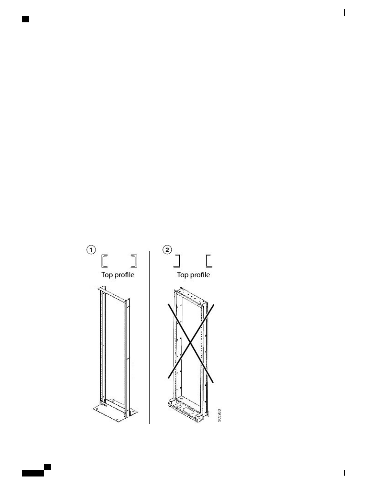
It is mandatory that the correct type of 19-inch ANSI rack is chosen to mount the NCS 2002 shelf. The
recommended shape of the rack post is shown in the figure below.
Figure 1: 19-inch ANSI Rack Post Recommended for Cisco NCS 2006 and 2002 Shelves
Cisco NCS 2000 Series Hardware Installation Guide
2
Page 31

Overview
Cisco NCS 2006 Shelf
1
recommended for the
Cisco NCS 2006 shelf
For proper airflow and cooling of the shelf, the shape of the vertical posts of the rack should be such that the
airflow vents are not covered. There must be sufficient space between the shelf side walls, and the vertical
walls of the rack post that are parallel to the shelf side walls, as shown in the figure below.
Figure 2: 19-inch Rack Opening for Air Flow
219-inch ANSI rack
19-inch ANSI rack
prohibited for the Cisco
NCS 2002 shelf
For information on hardware and software specifications for the NCS ETSI shelf, refer to the NCS 2002 Shelf
Specifications, on page 463.
Cisco NCS 2006 Shelf
The NCS 2006 is designed to comply with Telcordia GR-1089-CORE, Issue 5.
The NCS 2006 provides only Type 2 and Type 4 interfaces. A single NCS 2006 shelf supports both ANSI
and ETSI standards.
The NCS 2006 is FIPS 140-2 and CC compliant.
The NCS 2006 shelf has 8 horizontal card slots numbered 1 to 8. While Slot 2 to Slot 7 house MSTP cards
that provide 10 to 100 Gbps interconnections, Slot 1 and Slot 8 accommodate the TNC, TNCE, TSC, or TSCE
cards (timing and control cards). The NCS 2006 system can be powered by redundant AC or DC power
modules. A single power module (AC or DC) can be used to power up the entire NCS 2006 system. The NCS
2006 system contains backup flash memory that supports the database (DB) and image backup in the single
mode operation.
Rack2Empty space for air flow1
Shelf side wall3
Cisco NCS 2000 Series Hardware Installation Guide
3
Page 32

Cisco NCS 2015 Shelf
Overview
The front door of the NCS 2006 shelf allows access to the shelf, fan-tray assembly, fiber-routing area, power
connectors, external alarms and controls, timing input and output, and craft interface terminals. Two types of
front doors can be attached to the NCS 2006 shelf—the standard door and the deep-front panel. The front
door provides access to the shelf, and acts as a protective panel. The deep-front panel provides additional
space in front of the shelf to accommodate cables that do not fit inside the standard door. It also provides more
space for fiber bend radius and to manage the line card connections.The deep door does not have a hinge and
cannot be rotated like the standard door. The fiber or cable guide used in the NCS 2006 shelf provides improved
fiber management.
The NCS 2006 is mounted on a 19-inch or 23-inch ANSI rack (482.6 or 584.2 mm), or on a 600 x 600-mm
(23.6 x 23.6-inch) or 600 x 300-mm (23.6 x 11.8-inch) ETSI standard equipment rack. The rack mounting is
done using the mounting brackets or air deflectors. The air deflectors orient the air flow in a specific direction.
It is mandatory that the correct type of 19-inch ANSI rack is chosen to mount the NCS 2006 shelf. For proper
airflow and cooling of the shelf, the shape of the vertical posts of the rack should be such that the airflow
vents are not covered. There must be sufficient space between the shelf side walls, and the vertical walls of
the rack post that are parallel to the shelf side walls.
When installed in an equipment rack, the Cisco NCS 2006 shelf is typically connected to a fuse and alarm
panel to provide centralized alarm connection points and distributed power for the NCS 2006. Fuse and alarm
panels are third-party equipment and are not described in this documentation. If you are unsure about the
requirements or specifications for a fuse and alarm panel, consult the user documentation for the related
equipment.
The shelf with preinstalled air filter weighs approximately 23.55 pounds (10.680 kg) with no cards installed.
Note
Install and operate the NCS 2006 only in environments that do not expose wiring or cabling to the outside
plant.
For information on hardware and software specifications for the NCS ETSI shelf, see the NCS 2006 Shelf
Specifications, on page 467.
Cisco NCS 2015 Shelf
Watch the video for a brief overview of the Cisco NCS 2015 shelf.
The NCS 2015 is designed to comply with Telcordia GR-1089-CORE and Telcordia GR-63-CORE.
The NCS 2015 provides only Type 2 interfaces. A single NCS 2015 shelf is 14 rack units (RU) and supports
both ANSI and ETSI standards.
The NCS 2015 is FIPS 140-2 and CC compliant.
The NCS 2015 shelf has 18 vertical slots numbered 1 to 18. Slot 2 to Slot 16 is for line cards that provide 10
to 100 Gbps interconnections. Slot 1 and Slot 17 is for the TNCS or TNCS-O cards (timing and control cards).
Slot 18 is for the external connection unit (ECU). The NCS 2015 system can be powered by redundant AC
or DC power modules. The maximum chassis power is 5250 W. The NCS 2015 system contains backup flash
memory that supports the database (DB) and image backup in the single mode operation. The LCD unit is
Cisco NCS 2000 Series Hardware Installation Guide
4
Page 33

Overview
Cisco NCS 2015 Shelf
integrated with the fan tray assembly. The following figure shows the front view of the Cisco NCS 2015 DC
chassis.
Figure 3: Front View of the NCS 2015 DC Chassis
2Power modules1
Alarm dry contacts and
BITS in the power input
panel
4DC termination blocks3
Fan tray assembly with
LCD panel
5
6External connection unit
(ECU)
TNCS/TNCS-O cards in
slots 1 and 17
Air inlet8Line cards7
Cisco NCS 2000 Series Hardware Installation Guide
5
Page 34

Cisco NCS 2015 Shelf
Overview
The following figure shows the front view of the Cisco NCS 2015 AC chassis.
Figure 4: Front View of the NCS 2015 AC Chassis
2Power modules1
Alarm dry contacts and
BITS in the power input
panel
4AC cable connectors3
Fan tray assembly with
LCD panel
5
6External connection unit
(ECU)
TNCS/TNCS-O cards in
slots 1 and 17
Air inlet8Line cards7
Cisco NCS 2000 Series Hardware Installation Guide
6
Page 35

Overview
Cisco NCS 2015 Shelf
The front door of the NCS 2015 shelf allows access to the shelf, fan-tray assembly, fiber-routing area, power
connectors, external alarms and controls, timing input and output, and craft interface terminals. The front door
also acts as a protective panel. The fiber or cable guide used in the NCS 2015 shelf provides improved fiber
management.
The air in the NCS 2015 chassis is drawn in through a two-inch inlet at the bottom of the chassis, and expelled
at the top-rear as seen in the following figure.
Figure 5: Airflow Direction in the NCS 2015 DC Chassis
The NCS 2015 is mounted on a 19-inch or 23-inch ANSI rack (482.6 or 584.2 mm), or on a 600 x 300-mm
(23.6 x 11.8-inch) ETSI standard equipment rack. The rack is mounted using mounting brackets.
When installed in an equipment rack, the Cisco NCS 2015 shelf is typically connected to a fuse and alarm
panel to provide centralized alarm connection points and distributed power for the NCS 2015. Fuse and alarm
Cisco NCS 2000 Series Hardware Installation Guide
7
Page 36

Cisco NCS 2015 Shelf
Overview
panels are third-party equipment and are not described here. If you are unsure about the requirements or
specifications for a fuse and alarm panel, consult the user documentation for the related equipment.
The empty shelf weighs approximately 69.225 pounds (31.4 kg).
Note
Install and operate the NCS 2015 only in environments that do not expose wiring or cabling to the outside
plant.
For information on hardware and software specifications for the NCS shelf, see the NCS 2015 Shelf
Specifications, on page 473.
Cisco NCS 2000 Series Hardware Installation Guide
8
Page 37

Preparing to Install the Cisco NCS 2002, NCS 2006, and NCS 2015 Shelf
This chapter explains how to prepare for the Cisco NCS 2002, NCS 2006, and NCS 2015 shelf install.
The sections are:
Important Safety Recommendations, page 9
•
Required Tools and Equipment, page 10
•
Ordering Solutions for NCS 2002, NCS 2006, and NCS 2015, page 16
•
Card Slot Requirements, page 16
•
NTP-L41 Unpacking and Inspecting the Shelf, page 20
•
Important Safety Recommendations
CHAPTER 2
Warning
Warning
This warning symbol means danger. You are in a situation that could cause bodily injury. Before
you work on any equipment, be aware of the hazards involved with electrical circuitry and be
familiar with standard practices for preventing accidents. To see translations of the warnings that
appear in this publication, refer to the Regulatory Compliance and Safety Information document
for the appropriate Cisco chassis. Statement 274
Installation of the equipment must comply with local and national electrical codes. Statement 1074Warning
This equipment must be installed and maintained by service personnel as defined by AS/NZS 3260.
Incorrectly connecting this equipment to a general-purpose outlet could be hazardous. The
telecommunications lines must be disconnected 1) before unplugging the main power connector or
2) while the housing is open, or both. Statement 1043
Cisco NCS 2000 Series Hardware Installation Guide
9
Page 38

Required Tools and Equipment
Preparing to Install the Cisco NCS 2002, NCS 2006, and NCS 2015 Shelf
Warning
Warning
Warning
Note
Note
This unit is intended for installation in restricted access areas. A restricted access area can be
accessed only through the use of a special tool, lock and key, or other means of security. Statement
1017
Ultimate disposal of this product should be handled according to all national laws and regulations.
Statement 1040
A readily accessible two-poled disconnect device must be incorporated in the fixed wiring. Statement
1022
The NCS 2002, NCS 2006, and NCS 2015 are suitable for mounting on concrete or other noncombustible
surfaces only.
In this chapter, “shelf” refers to the steel enclosure that holds cards and connects power, and “node” refers
to the entire hardware and software system. Unless otherwise specified, NCS 2002, NCS 2006, and NCS
2015 refers to both ANSI and ETSI environments.
Note
The NCS 2006 is suitable for installation in network telecommunication facilities where the National
Electric Code (NEC) applies.
Required Tools and Equipment
The following sections describe the tools and equipment you need to install and test the NCS 2002, NCS
2006, or NCS 2015 shelves.
Cisco Supplied Materials
The following table lists the materials that are required to install, and are shipped with the NCS 2002, NCS
2006, and NCS 2015 shelves (wrapped in plastic). The shipped quantity of each item is in parentheses.
Note
To avoid damage during shipment, either a standard front door or a temporary front door is preinstalled
in the Cisco NCS 2006 shelves. If a front door is ordered, a standard front door is preinstalled. If a front
door is not ordered, a temporary front door is preinstalled.
Cisco NCS 2000 Series Hardware Installation Guide
10
Page 39

Preparing to Install the Cisco NCS 2002, NCS 2006, and NCS 2015 Shelf
Table 1: Cisco Supplied Materials Required to Install
Cisco Supplied Materials
NCS 2015NCS 2006NCS 2002Cisco Supplied Material
Bracket Cover
Cables
Grounding Lug
ANSI
RJ LAN cable bracket cover (1)
Rubber bumpers (4)Bumpers
Cable assembly, Ethernet,
RJ-45 (1)
Double-hole grounding
•
lug for ground connection
with a wire receptacle to
accommodate the
recommended 13.3 mm²
(#6 AWG) multistrand
copper wire (1).
Double-hole grounding
•
lug for ground connection
with a wire receptacle to
accommodate the
recommended 13.3 mm²
(#6 AWG) multistrand
copper wire angled at 45
degree (1)
ANSIRJ LAN bracket (1)ANSIRJ LAN bracket (1)Brackets
ANSI
RJ LAN cable bracket cover (1)
Cable assembly, Ethernet,
RJ-45 (1)
Double-hole grounding
•
lug for ground connection
with a wire receptacle to
accommodate the
recommended 13.3 mm²
(#6 AWG) multistrand
copper wire (1)
Double-hole grounding
•
lug for ground connection
with a wire receptacle to
accommodate the
recommended 13.3 mm²
(#6 AWG) multistrand
copper wire angled at 45
degree (1)
—
—
—
—
Emery cloth (1)Emery cloth (1)Emery cloth (1)Emery Cloth
ESD wrist strap (disposable) (1)ESD wrist strap (disposable) (1)ESD wrist strap (disposable) (1)ESD wrist strap
Double-hole grounding lug for
ground connection with a wire
receptacle to accommodate the
recommended 21.2 mm² (#4
AWG) multistrand copper wire
(1)
Mounting Brackets
M6 lock washers (8)Lock Washers
Reversible ANSI 19"/23"
bracket and ETSI bracket
Lacing twine (1)Lacing twine (1)Lacing Twine
ANSI
M6 lock washers (8)
Reversible ANSI 19"/23"
bracket and ETSI bracket
Cisco NCS 2000 Series Hardware Installation Guide
—
—
ANSI 19" bracket (EIA), ANSI
23" bracket (EIA), ANSI 23” Z
bracket (EIA), and ETSI bracket
11
Page 40

Cisco Supplied Materials
Preparing to Install the Cisco NCS 2002, NCS 2006, and NCS 2015 Shelf
NCS 2015NCS 2006NCS 2002Cisco Supplied Material
Power Lug
Mounting bracket screws
Deep door bracket screws and
washer
ANSI
Double-hole power lug for DC
power connection with a wire
receptacle to accommodate the
recommended 8.4 mm² (#8
AWG) multistrand copper wire
(1)
ANSI#12-24 x 0.50 pan-head
Phillips screws (8)
ETSI
M6.0 x 20 pan-head Phillips
screws (8)
—
ANSI
#12-24 x 0.50 pan-head Phillips
screws (8)
ETSI
M6.0 x 20 pan-head Phillips
screws (8)
——
Double-hole power lug for DC
power connection with a wire
receptacle to accommodate the
recommended 13.29 mm² (#6
AWG) multistrand copper wire.
Based on the door that is
installed, use either short barrel
lugs or long barrel lugs:
• Standard door—Use short
barrel lug (16)
• Deep door—Use long
barrel lug (16)
ANSI
M4.0 x 6mm flat-head Phillips
screws (10)
ETSI
M4.0 x 6 flat-head Phillips
screws (10)
M3 x 10 mm screws (10)
•
M3 x 8 mm screw (1) and
•
safety washer (1)
Screws and lock washers for
grounding the chassis
Mounting screws and washers
——
M6.0 x 16mm pan-head
•
Phillips screws (2)
M6 lock washers (2)
•
Tie wraps (10)Tie wraps (10)Tie wraps (10)Tie Wraps
——
ANSI
•
#12-24 x 0.50 inch pan-head
Phillips mounting screws (16)
ETSI
•
M6 x 20 mm pan-head Phillips
mounting screws (16)
Washers (16)
•
Cisco NCS 2000 Series Hardware Installation Guide
12
Page 41

Preparing to Install the Cisco NCS 2002, NCS 2006, and NCS 2015 Shelf
User Supplied Materials
NCS 2015NCS 2006NCS 2002Cisco Supplied Material
Screw for ground strap cable
Anti-oxidant
Caution
Only use the power cables that are designed to be used with the NCS 2002, NCS 2006, or NCS 2015.
These are sold separately.
User Supplied Materials
The following materials, tools, and equipment are required but are not supplied with the NCS 2002, NCS
2006, and NCS 2015.
Table 2: User Supplied Materials
Bit error rate (BER) tester
BNC insertion tool
——
——
M3 x 6 mm screw (1)
Anti-oxidant (1)
NCS 2015NCS 2006NCS 2002User Supplied Material
———
———
Chassis grounding, connecting
power
1/4" socket wrench, sockets,
and a torque wrench
1/4" socket wrench, sockets,
and a torque wrench
1/4" socket wrench, sockets,
and a torque wrench
Cisco NCS 2000 Series Hardware Installation Guide
13
Page 42

User Supplied Materials
Preparing to Install the Cisco NCS 2002, NCS 2006, and NCS 2015 Shelf
NCS 2015NCS 2006NCS 2002User Supplied Material
Cables
ANSI
Power cable (from fuse
•
and alarm panel to
assembly), #12 AWG or
larger, copper conductors,
194 degrees Fahrenheit
(90 degrees Celsius).
Ground cable #6 AWG
•
stranded
Alarm cable pairs for all
•
alarm connections, #22 or
#24 AWG (0.51 mm² or
0.64 mm²), solid tinned.
100-ohm shielded
•
building integrated timing
supply (BITS) clock cable
pair #22 or #24 AWG
(0.51 mm² or 0.64 mm²),
twisted-pair T1-type
ETSI
Copper ground cable
•
13.3-mm² (#6 AWG)
stranded, specified for up
to 90 degrees Celsius (194
degrees Fahrenheit)
ANSI
Power cable (from fuse
•
and alarm panel to
assembly), #8 AWG or
larger, copper conductors,
194 degrees Fahrenheit
(90 degrees Celsius).
Ground cable #6 AWG
•
stranded
Alarm cable pairs for all
•
alarm connections, #22 or
#24 AWG (0.51 mm² or
0.64 mm²), solid tinned.
100-ohm shielded
•
building integrated timing
supply (BITS) clock cable
pair #22 or #24 AWG
(0.51 mm² or 0.64 mm²),
twisted-pair T1-type
ETSI
Copper ground cable
•
13.3-mm² (#6 AWG)
stranded, specified for up
to 90 degrees Celsius (194
degrees Fahrenheit)
Power cable (from fuse
•
and alarm panel to
assembly), #6 AWG,
copper conductors, 194
degrees Fahrenheit (90
degrees Celsius).
Ground cable #4 AWG
•
stranded
Alarm cable pairs for all
•
alarm connections, #22 or
#24 AWG (0.51 mm² or
0.64 mm²), solid tinned.
ANSI
100-ohm shielded
•
building integrated timing
supply (BITS) clock cable
pair #22 or #24 AWG
(0.51 mm² or 0.64 mm²),
twisted-pair T1-type
ETSI
75-ohm coaxial cable with
•
a DIN-1.0/2.3 miniature
coaxial connector.
Crimp tool
Alarm cable pairs for all
•
alarm connections, 0.51
mm² or 0.64 mm² (#22 or
#24 AWG), solid-tinned
Crimping tool—This tool must
be large enough to
accommodate the girth of the
grounding lug when you crimp
the grounding cable into the lug.
Use the lug manufacturer’s
suggested dye for crimping.
Alarm cable pairs for all
•
alarm connections, 0.51
mm² or 0.64 mm² (#22 or
#24 AWG), solid-tinned
Crimping tool—This tool must
be large enough to
accommodate the girth of the
grounding lug when you crimp
the grounding cable into the lug.
Use the lug manufacturer’s
suggested dye for crimping.
CLETOP cleaning cassetteCLETOP cleaning cassetteCLETOP cleaning cassetteCleaning Cassette
Crimping tool—This tool must
be large enough to
accommodate the girth of the
grounding lug when you crimp
the grounding cable into the lug.
Use the lug manufacturer’s
suggested dye for crimping.
Cisco NCS 2000 Series Hardware Installation Guide
14
Page 43

Preparing to Install the Cisco NCS 2002, NCS 2006, and NCS 2015 Shelf
User Supplied Materials
NCS 2015NCS 2006NCS 2002User Supplied Material
Fuse and Alarm panel
Jumper
Power Meter
Rack
ANSI
Fuse and alarm panel
ETSI
Fuse and alarm panel
Single-mode SC fiber jumpers
with UPC polish (55 dB or
better) for optical (OC-N) cards
Optical power meter (for use
with fiber optics only)
ANSI
19-inch ANSI Standard
•
(Telcordia GR-63-CORE)
(482.6 mm) rack; total
width 22 inches (558.8
mm)
23-inch ANSI Standard
•
(Telcordia GR-63-CORE)
(584.2 mm) rack; total
width 26 inches (660.4
mm)
ANSI
Fuse and alarm panel
ETSI
Fuse and alarm panel
Single-mode SC fiber jumpers
with UPC polish (55 dB or
better) for optical (OC-N) cards
LabelsLabelsLabelsLabels
Optical power meter (for use
with fiber optics only)
ANSI
19-inch ANSI Standard
•
(Telcordia GR-63-CORE)
(482.6 mm) rack; total
width 22 inches (558.8
mm)
23-inch ANSI Standard
•
(Telcordia GR-63-CORE)
(584.2 mm) rack; total
width 26 inches (660.4
mm)
Screw Driver
Tie wraps and/or lacing cord
Video fiber connector
inspection instrument
ETSI
Equipment rack (ETSI rack,
2200 mm [86.6 inch] H x 600
mm [23.6 inch] Wx 300 mm
[11.8 inch] D)
#2 Phillips Dynamometric
•
screwdriver
Medium slot-head
•
screwdriver
Small slot-head screw
•
driver
Tie wraps or lacing cord (or
both)
Video fiber connector
inspection instrument
ETSI
Equipment rack (ETSI rack,
2200 mm [86.6 inch] H x 600
mm [23.6 inch] Wx 300 mm
[11.8 inch] D)
#2 Phillips Dynamometric
•
screwdriver
Medium slot-head
•
screwdriver
Small slot-head screw
•
driver
Tie wraps or lacing cord (or
both)
Video fiber connector
inspection instrument
ETSI
Equipment rack (ETSI rack,
2200 mm [86.6 inch] H x 600
mm [23.6 inch] Wx 300 mm
[11.8 inch] D)
#2 Phillips Dynamometric
•
screwdriver
Medium slot-head
•
screwdriver
Small slot-head screw
•
driver
Tie wraps or lacing cord (or
both)
Video fiber connector
inspection instrument
Cisco NCS 2000 Series Hardware Installation Guide
15
Page 44

Preparing to Install the Cisco NCS 2002, NCS 2006, and NCS 2015 Shelf
Ordering Solutions for NCS 2002, NCS 2006, and NCS 2015
NCS 2015NCS 2006NCS 2002User Supplied Material
VoltmeterVoltmeterVoltmeterVoltmeter
Wire cuttersWire cuttersWire cuttersWire Cutters
Wire strippersWire strippersWire strippersWire Strippers
Wire wrapperWire wrapperWire wrapperWire Wrapper
Ring runs are not provided by Cisco and can hinder side-by-side shelf installation where space is limited.Note
Ordering Solutions for NCS 2002, NCS 2006, and NCS 2015
Two ordering solutions for the NCS 2002 shelf are offered. Select one of these solutions:
Shelf that is preinstalled with all the ancillary units such as fan tray assembly and power module.
•
Shelf that is not preinstalled with the ancillary units but can be ordered separately.
•
In both the ordering solutions, the front door is preinstalled with the NCS 2002 shelf.Note
Two ordering solutions for the Cisco NCS 2006 shelf are offered. Select one of these solutions:
Shelf assembly that is preinstalled with all the ancillary units such as fan tray assembly, LCD unit, power
•
module and NCS 2006 ECU.
Shelf assembly that is not preinstalled with the ancillary units but can be ordered separately.
•
One ordering solution for the Cisco NCS 2015 shelf is offered.
Shelf assembly that is not preinstalled with the ancillary units but can be ordered separately.
•
Card Slot Requirements
The cards have electrical plugs at the back that plug into electrical connectors on the shelf backplane. When
the ejectors are fully closed, the card plugs into the assembly backplane.
NCS 2002
Cisco NCS 2000 Series Hardware Installation Guide
16
The NCS 2002 shelf assemblies have 3 card slots numbered sequentially from bottom to top. Slot 1 is reserved
for control cards (TNC, TNCE, TSC, or TSCE). Slot 2 and Slot 3 are dedicated for common line cards.
Page 45

Preparing to Install the Cisco NCS 2002, NCS 2006, and NCS 2015 Shelf
The NCS 2002 shelf must be equipped with a TNC, TNCE, TSC, or TSCE card.Caution
Shelf slots have symbols indicating the type of cards that you can install in them. Each NCS 2002 card has a
corresponding symbol. The symbol on the card must match the symbol on the slot.
Figure 6: Slot Symbols
The following table shows the slot and card symbol definitions.
Table 3: Slot and Card Symbols
NCS 2006
DefinitionSymbol Color/Shape
NCS 2006
Caution
Purple/Square
Slot 1. TNC/TNCE/TSC/TSCE card slot. Only install
the card with a square symbol on the faceplate.
Orange/Circle
Slots 2 and 3. Only install cards with a circle symbol
on the faceplate.
Orange/Hollow Circle
Slots 2 to 3. New line cards with high speed back
plane connectors.
Slots 2 and 3. New Uplink card.Pink/Pentagon
The NCS 2006 shelf assemblies have eight card slots numbered sequentially from bottom to top. Slots 1 and
8 are reserved for control cards (TNC, TNCE, TSC, or TSCE). Slots 2, 3, 4, 5, 6, and 7 are dedicated for
common line cards.
The NCS 2006 system can work with a single control card (TNC, TNCE, TSC, or TSCE). The TNC,
TNCE, TSC, and TSCE cards cannot operate in a shelf at the same time.
The shelf assembly slots have symbols indicating the type of cards that you can install in them. Each card has
a corresponding symbol. The symbol on the card must match the symbol on the slot.
Figure 7: Slot Symbols
Cisco NCS 2000 Series Hardware Installation Guide
17
Page 46

NCS 2015
Preparing to Install the Cisco NCS 2002, NCS 2006, and NCS 2015 Shelf
The following shows the slot and card symbol definitions.
Table 4: Slot and Card Symbols
DefinitionSymbol Color/Shape
NCS 2015
Note
Purple/Square
Slots 1 and 8. TNC/TNCE/TSC/TSCE card slot.
Install cards only with a square symbol on the
faceplate.
Orange/Circle
Slots 2 to 7. Install cards only with a circle symbol
on the faceplate.
Orange/Hollow Circle
Slots 2 to 7. New line cards with high-speed
backplane connectors.
Slots 4 and 5. New Uplink card.Pink/Pentagon
When the NCS 2006 shelf is powered at –60 VDC (nominal), only TNC, OPT-AMP-C, OPT-AMP-17-C,
OPT-EDFA-17, OPT-EDFA-24, and NCS 2006 ECU can be installed.
The NCS 2015 shelf assemblies have 18 card slots numbered sequentially from left to right. Slots 1 and 17
are reserved for control cards (TNCS or TNCS-O). Slots 2 through 16 are dedicated for common line cards
and slot 18 is reserved for the ECU.
The NCS 2015 system can work with a single control card (TNCS or TNCS-O.)Caution
Cisco NCS 2000 Series Hardware Installation Guide
18
Page 47

Preparing to Install the Cisco NCS 2002, NCS 2006, and NCS 2015 Shelf
The shelf assembly slots have symbols indicating the type of cards that you can install in them. Each card has
a corresponding symbol. The symbol on the card must match the symbol on the slot.
Figure 8: Slot Symbols
The folowing table shows the slot and card symbol definitions.
Card Replacement
Table 5: Slot and Card Symbols
Orange/Circle
Pink/Triangle
Blue/Hexagon
Card Replacement
To replace a card with another card of the same type, you do not need to make any changes to the database;
remove the old card and replace it with a new card. To replace a card with a card of a different type, physically
remove the card and replace it with the new card, then delete the original card from CTC. For specifics, refer
to the “Maintain the Node” chapter in the Cisco NCS 2000 Series Network Configuration Guide .
DefinitionSymbol Color/Shape
Slots 1 and 17. TNCS or TNCS-O card slot.Purple/Square
Slots 2 through 16. Install only cards with a circle
symbol on the faceplate.
Slots 2 through 16. Install only line cards with circle
or a triangle symbol on the faceplate.
Slots 2 through 16. Install only line cards with a blue
hexagon symbol on the faceplate.
Slot 18. ECU slot.Green/Pentagon
Caution
Removing any active card from the shelf can result in traffic interruption. Use caution when replacing
cards and verify that only inactive or standby cards are being replaced. If the active card needs to be
replaced, switch it to standby prior to removing the card from the node.
Cisco NCS 2000 Series Hardware Installation Guide
19
Page 48

NTP-L41 Unpacking and Inspecting the Shelf
Preparing to Install the Cisco NCS 2002, NCS 2006, and NCS 2015 Shelf
Note
An improper removal (IMPROPRMVL) alarm is raised whenever a card pull (reseat) is performed, unless
the card is deleted in CTC first. The alarm clears after the card replacement is complete.
NTP-L41 Unpacking and Inspecting the Shelf
Purpose
Procedure
This procedure explains how to unpack the NCS 2002,
NCS 2006, and NCS 2015 shelves and verify their
contents.
NoneTools/Equipment
NonePrerequisite Procedures
RequiredRequired/As Needed
OnsiteOnsite/Remote
NoneSecurity Level
Step 1
Step 2
Complete the DLP-L62 Unpacking and Verifying the Shelf , on page 20.
Complete the DLP-L63 Inspecting the Shelf, on page 22.
Stop. You have completed this procedure.
DLP-L62 Unpacking and Verifying the Shelf
This task removes the shelves from the package.Purpose
NoneTools/Equipment
NonePrerequisite Procedures
RequiredRequired/As Needed
OnsiteOnsite/Remote
NoneSecurity Level
Cisco NCS 2000 Series Hardware Installation Guide
20
Page 49

Preparing to Install the Cisco NCS 2002, NCS 2006, and NCS 2015 Shelf
Procedure
DLP-L62 Unpacking and Verifying the Shelf
Step 1
Step 2
Step 3
When you receive the NCS 2002, NCS 2006, or NCS 2015 system equipment at the installation site, open
the top of the box. The Cisco Systems logo designates the top of the box.
Remove the foam inserts from the box. The box contains the NCS shelf (wrapped in plastic) and a smaller
box of items needed for installation.
To remove the shelf, grasp both rings of the shelf removal strap and slowly lift the shelf out of the box. The
NCS 2015 chassis has lifting handles at either side for this purpose (see figure below).
Figure 9: Handling the NCS 2015 DC Chassis During Installation
Cisco NCS 2000 Series Hardware Installation Guide
21
Page 50

DLP-L63 Inspecting the Shelf
Preparing to Install the Cisco NCS 2002, NCS 2006, and NCS 2015 Shelf
Lifting handle1
Step 4
Open the smaller box of installation materials, and verify that you have all items listed in the Required Tools
and Equipment, on page 10.
Note
If the NCS 2006 shelf and ancillary units are ordered separately, then the power modules, LCD
module, NCS HIG 2006 ECU module, fan-tray assembly, and mounting brackets are shipped
separately.
Step 5
Return to your originating procedure (NTP).
DLP-L63 Inspecting the Shelf
Purpose
Prerequisite Procedures
This task verifies that all parts of the shelf are in good
condition.
NoneTools/Equipment
DLP-L62 Unpacking and Verifying the Shelf , on
page 20
RequiredRequired/As Needed
OnsiteOnsite/Remote
Step 1
Step 2
Step 3
Step 4
NoneSecurity Level
Procedure
(Cisco NCS 2002 and NCS 2006) Open the shelf removing temporary door or standard door. For more
information, see the DLP-L46 Removing the Standard Door of the NCS 2002 Shelf, on page 113 and DLP-L13
Removing the Standard Door of the NCS 2006 Shelf , on page 255.
Verify the following:
The pins are not bent or broken.
•
The frame is not bent.
•
If the pins are bent or broken, or the frame is bent, call your Cisco sales engineer for a replacement.
Return to your originating procedure (NTP).
Cisco NCS 2000 Series Hardware Installation Guide
22
Page 51

CHAPTER 3
Cisco NCS 2002 Installation Overview
This chapter provides an overview of the NCS 2002 installation.
Cisco NCS 2002 Installation Overview, page 23
•
Cisco NCS 2002 Installation Overview
This chapter includes these sections:
Mounting the brackets
•
Mounting the shelf
•
Installing the door and other modules
•
Connecting the power and ground
•
Connecting and routing the cables
•
Installing and configuring the control card
•
Performing the shelf acceptance test
•
Cisco NCS 2000 Series Hardware Installation Guide
23
Page 52

Cisco NCS 2002 Installation Overview
Cisco NCS 2002 Installation Overview
Cisco NCS 2000 Series Hardware Installation Guide
24
Page 53

CHAPTER 4
Installing the Air Flow Regulator
This chapter explains how to install the regulators to maintain the air flow for ANSI and ETSI configurations
in NCS 2002 shelf.
The air flow within the equipment must be maintained at a nominal temperature. This task can be accomplished
using one of these mechanisms:
Air deflector
•
Air plenum
•
The sections are:
Air Deflector, page 25
•
Air Plenum, page 26
•
Air Plenum Rack and Cabinet Compatibility, page 27
•
NTP-L42 Install the Air Plenum in NCS 2002 Shelf, page 28
•
Air Deflector
An air deflector is a sheet-metal part that is mounted on the NCS 2002 shelf to orient the air flow in a specific
direction.
The air deflectors can be mounted in different positions to control the air flow:
In an ANSI rack, the air deflectors are mounted only on the 23-inch rack configuration.
• Front to Front— Only ETSI rack
• Front to Back— For ANSI and ETSI racks
• Front to Top— Only ETSI rack
Cisco NCS 2000 Series Hardware Installation Guide
25
Page 54

Air Plenum
Air Plenum
Installing the Air Flow Regulator
Air plenum orients the air flow in the front-to-back direction inside the equipment to be compliant with GR-63
issue 4 requirement.
NCS 2002 air plenum kit has one horizontal and two vertical air plenums. The air that flows from the front
top inlet are channelized to the right vertical plenum, inside the equipment, and then to the exhaust air channel
towards the left vertical air plenum. The air flow is deflected by 90 degrees and exited out in the rear end.
The following figure shows the air flow inside the air plenum.
Figure 10: Air flow within the air plenum
Cisco NCS 2000 Series Hardware Installation Guide
26
Page 55

Installing the Air Flow Regulator
The following figures show the dimensions of the air plenum relative to the cabinet or rack.
Figure 11: Dimension of Cisco NCS 2002 chassis relative to the air plenum
Air Plenum Rack and Cabinet Compatibility
Figure 12: Dimension of Cisco NCS 2002 chassis relative to the air plenum
Air Plenum Rack and Cabinet Compatibility
The table shows the compatibility of air plenum with the ANSI and ETSI racks and cabinets. The chassis can
be installed with brackets in front position only.
Table 6: Air plenum compatibility with racks and cabinets
ANSI 19-inch rack
ANSI 19-inch cabinet
Front-to-back air flowRack / Cabinet
Supported
Supported
Cisco NCS 2000 Series Hardware Installation Guide
1
1
27
Page 56

NTP-L42 Install the Air Plenum in NCS 2002 Shelf
Installing the Air Flow Regulator
Front-to-back air flowRack / Cabinet
SupportedANSI 23-inch rack
SupportedANSI 23-inch cabinet
ETSI cabinet
1
A minimum opening of 20.600 inches is required to install the vertical air plenum behind the front rails.
Note
The ANSI 19-inch two post rack that is compatible with air plenum installation is available from Telect,
Supported
with part number 12545-301.
Figure 13: Minimum rear opening for ANSI 19-inch and ETSI configuration
1
NTP-L42 Install the Air Plenum in NCS 2002 Shelf
Purpose
Cisco NCS 2000 Series Hardware Installation Guide
28
This procedure installs the air plenum to orient the
air flow in front-to- back direction in the NCS 2002
shelf.
Page 57

Installing the Air Flow Regulator
NTP-L42 Install the Air Plenum in NCS 2002 Shelf
Tools/Equipment
#2 Phillips Dynamometric screwdriver
•
Medium slot-head screwdriver
•
Small slot-head screwdriver
•
Screws
•
ANSI: #12-24 x 0.50 pan-head Phillips
◦
screws
ETSI: M6.0 x 20 pan-head Phillips screws
◦
Wing head screws (4)
•
Adapter plates
•
One air plenum kit (horizontal and vertical air
•
plenums)
As neededRequired/As Needed
OnsiteOnsite/Remote
NoneSecurity Level
Warning
Warning
Warning
Note
Before performing any of the following procedures, ensure that power is removed from the DC
circuit. Statement 1074
Before working on a chassis or working near power supplies, unplug the power cord on AC units.
Statement 246
This equipment is intended to be grounded. Ensure that the host is connected to earth ground during
normal use. Statement 39
For nominal voltage of -60 VDC, the input voltage range is from -40 to -72 VDC.Note
Use only the fastening hardware provided with the NCS 2002 to prevent loosening, deterioration, and
electromechanical corrosion of the hardware and joined material.
Cisco NCS 2000 Series Hardware Installation Guide
29
Page 58

DLP-L65 Installing Air Plenum for NCS 2002 Shelf in ANSI 19-inch Configuration
Installing the Air Flow Regulator
Warning
Warning
When installing or replacing the unit, the ground connection must always be made first and
disconnected last. Statement 1046
The air plenum is installed on a rack or a cabinet using thread-forming screws that remove any
paint or non-conductive coatings inside the hole threads, and establish a metal-to-metal contact.
Also, clean both surfaces outside the screw points that come in contact, so that they are free of paint
and other nonconductive coating. Apply an appropriate antioxidant compound to the surfaces.
Procedure
Depending on the rack or cabinet, complete the necessary task:
DLP-L65 Installing Air Plenum for NCS 2002 Shelf in ANSI 19-inch Configuration, on page 30
•
DLP-L69 Installing Air Plenum in NCS 2002 Shelf for ANSI 23-inch Configuration, on page 33
•
DLP-L70 Installing Air Plenum for NCS 2002 Shelf in ETSI Configuration, on page 40
•
DLP-L71 Installing Pre-assembled Air Plenums in ANSI 23-inch Configuration, on page 38
•
Stop. You have completed this procedure.
DLP-L65 Installing Air Plenum for NCS 2002 Shelf in ANSI 19-inch Configuration
Purpose
Tools/Equipment
This task installs the air plenum for the NCS 2002
shelf in ANSI 19-inch cabinet or rack configuration.
#2 Phillips Dynamometric screwdriver
•
Medium slot-head screwdriver
•
Small slot-head screwdriver
•
Screws: #12-24 x 0.50 pan-head Phillips screws
•
(4)
Wing head screws (4)
•
One air plenum kit (horizontal and vertical air
•
plenum)
As neededRequired/As Needed
OnsiteOnsite/Remote
NoneSecurity Level
Cisco NCS 2000 Series Hardware Installation Guide
30
Page 59

Installing the Air Flow Regulator
DLP-L65 Installing Air Plenum for NCS 2002 Shelf in ANSI 19-inch Configuration
Note
Step 1
Step 2
In the 19-inch rack and cabinet, the air plenum can be mounted only if the minimum opening is 20.600
inches to install the vertical air plenums behind the front rails.
Procedure
Place the horizontal air plenum above the shelf slot in the ANSI 19-inch cabinet or rack.
Insert the wing head screws provided with the kit, and tighten to a torque value of 11.5 in-lb (1.3 N-m).
Figure 14: Installing the horizontal air plenum in the ANSI 19-inch configuration
Step 3
Install the vertical air plenum to the left of the horizontal air plenum:
a) Insert the vertical plenum in the free space between the horizontal plenum and cabinet.
b) Install t he wing head screws fom the internal side of the horizontal plenum as shown in the following
figure.
Cisco NCS 2000 Series Hardware Installation Guide
31
Page 60

DLP-L65 Installing Air Plenum for NCS 2002 Shelf in ANSI 19-inch Configuration
c) Tighten the screws to a torque value of 11.5 in-lb (1.3 N-m).
Figure 15: Installing the left vertical air plenum
Installing the Air Flow Regulator
Step 4
Install the vertical air plenum to the right of the horizontal air plenum. Follow step 3a to 3c.
Figure 16: Installing the right vertical air plenum
Cisco NCS 2000 Series Hardware Installation Guide
32
Page 61

Installing the Air Flow Regulator
DLP-L69 Installing Air Plenum in NCS 2002 Shelf for ANSI 23-inch Configuration
Step 5
Step 6
Install the 19-inch standard brackets on both sides of the chassis in the front position. See DLP-L35 Mounting
the 19-inch Brackets on the NCS 2002 Shelf for ANSI Rack Configuration, on page 46.
Install the NCS 2002 empty chassis below the horizontal plenum.
Figure 17: Installing the NCS 2002 chassis below the horizontal air plenum
Step 7
Return to your originating procedure (NTP).
DLP-L69 Installing Air Plenum in NCS 2002 Shelf for ANSI 23-inch Configuration
Purpose
This task installs the air plenum for the NCS 2002
shelf in the ANSI 23-inch cabinet or rack
configuration.
Cisco NCS 2000 Series Hardware Installation Guide
33
Page 62

DLP-L69 Installing Air Plenum in NCS 2002 Shelf for ANSI 23-inch Configuration
Installing the Air Flow Regulator
Note
Tools/Equipment
#2 Phillips Dynamometric screwdriver
•
Medium slot-head screwdriver
•
Small slot-head screwdriver
•
Screws: #12-24 x 3/4 pan-head Phillips
•
mounting screws (4)
Wing head screws (4)
•
Adapter plates
•
One air plenum kit (horizontal and vertical air
•
plenum)
As neededRequired/As Needed
OnsiteOnsite/Remote
NoneSecurity Level
The air plenums for ANSI 23-inch configuration can also be pre-assembled outside the cabinet and then
installed inside the cabinet. See DLP-L71 Installing Pre-assembled Air Plenums in ANSI 23-inch
Configuration, on page 38
Cisco NCS 2000 Series Hardware Installation Guide
34
Page 63

Installing the Air Flow Regulator
Procedure
DLP-L69 Installing Air Plenum in NCS 2002 Shelf for ANSI 23-inch Configuration
Step 1
Step 2
Install the ANSI 23-inch adapter plates on the horizontal air plenum.
Align the screws to fix the adapter plates to the shelf. Insert the screws and tighten them to a torque value of
11.5 in-lb (1.3 N-m).
Figure 18: Installing the adapter plates on the horizontal air plenum
Cisco NCS 2000 Series Hardware Installation Guide
35
Page 64

DLP-L69 Installing Air Plenum in NCS 2002 Shelf for ANSI 23-inch Configuration
Installing the Air Flow Regulator
Step 3
Step 4
Step 5
Place the horizontal air plenum above the shelf slot in the ANSI 23-inch cabinet or rack.
Insert the wing head screws provided with the kit, and tighten to a torque value of 11.5 in-lb (1.3 N-m).
Figure 19: Installing the horizontal air plenum in the ANSI 23-inch configuration
Install the vertical air plenum to the left of the horizontal air plenum:
a) Insert the vertical air plenum in the free space between the horizontal air plenum and cabinet.
b) Install the wing head screws from the internal side of the horizontal plenum as shown in the following
figure.
c) Tighten the screws to a torque value of 11.5 in-lb (1.3 N-m).
Figure 20: Installing the left vertical air plenum
Cisco NCS 2000 Series Hardware Installation Guide
36
Page 65

Installing the Air Flow Regulator
DLP-L69 Installing Air Plenum in NCS 2002 Shelf for ANSI 23-inch Configuration
Step 6
Install the vertical plenum to the right of the horizontal air plenum. Follow step 5a to 5c.
Figure 21: Installing the right vertical air plenum
Step 7
Step 8
Install ANSI 19-inch standard brackets on both sides of the chassis in front position. See DLP-L35 Mounting
the 19-inch Brackets on the NCS 2002 Shelf for ANSI Rack Configuration, on page 46.
Install the NCS 2002 empty chassis below the horizontal plenum.
Figure 22: Installing the NCS 2002 chassis below the horizontal air plenum
Cisco NCS 2000 Series Hardware Installation Guide
37
Page 66

DLP-L71 Installing Pre-assembled Air Plenums in ANSI 23-inch Configuration
Installing the Air Flow Regulator
Step 9
Return to your originating procedure (NTP).
DLP-L71 Installing Pre-assembled Air Plenums in ANSI 23-inch Configuration
Purpose
Tools/Equipment
This task installs pre-assembled air plenums for the
NCS 2002 shelf in the ANSI 23-inch configuration.
#2 Phillips Dynamometric screwdriver
•
Medium slot-head screwdriver
•
Small slot-head screwdriver
•
Screws: #12-24 x 3/4 pan-head Phillips
•
mounting screws (8)
Wing head screws (4)
•
Adapter plates
•
One air plenum kit (horizontal and vertical air
•
plenum)
As neededRequired/As Needed
OnsiteOnsite/Remote
NoneSecurity Level
Cisco NCS 2000 Series Hardware Installation Guide
38
Page 67

Installing the Air Flow Regulator
Procedure
DLP-L71 Installing Pre-assembled Air Plenums in ANSI 23-inch Configuration
Step 1
Step 2
Step 3
Step 4
Step 5
Install the ANSI 23-inch adapter plates on the horizontal air plenum.
Align the screws to fix the adapter plates to the shelf. Insert the screws and tighten them to a torque value of
11.5 in-lb (1.3 N-m).
Install the vertical air plenum to the right of the horizontal plenum.
Install the wing head screws from the internal side of the horizontal plenum and tighten the screws to a torque
value of 11.5 in-lb (1.3 N-m).
Install the vertical air plenum to the left of the horizontal air plenum. Follow step 4.
Figure 23: Pre-assembling the air plenums
Cisco NCS 2000 Series Hardware Installation Guide
39
Page 68

DLP-L70 Installing Air Plenum for NCS 2002 Shelf in ETSI Configuration
Installing the Air Flow Regulator
Step 6
Step 7
Step 8
Install the pre-assembled air plenum for ANSI 23-inch configuration.
Figure 24: Pre-assembled air plenum
Install the empty NCS 2002 chassis between the horizontal plenums.
Return to your originating procedure (NTP).
DLP-L70 Installing Air Plenum for NCS 2002 Shelf in ETSI Configuration
Purpose
Tools/Equipment
This task installs the air plenum for the NCS 2002
shelf in the ETSI configuration.
#2 Phillips Dynamometric screwdriver
•
Medium slot-head screwdriver
•
Small slot-head screwdriver
•
Screws: M6.0 x 20 pan-head Phillips screws (4)
•
Wing head screws (4)
•
Adapter plates
•
One air plenum kit (horizontal and vertical air
•
plenum)
As neededRequired/As Needed
OnsiteOnsite/Remote
Cisco NCS 2000 Series Hardware Installation Guide
40
Page 69

Installing the Air Flow Regulator
Procedure
DLP-L70 Installing Air Plenum for NCS 2002 Shelf in ETSI Configuration
NoneSecurity Level
Step 1
Step 2
Install the ETSI adapter plates on the horizontal air plenum.
Align the screws to fix the adapter plates to the horizontal air plenum. Insert the screws and tighten them to
a torque value of 11.5 in-lb (1.3 N-m) as shown in the following figure.
Figure 25: Installing the adapter plates on the horizontal air plenum
Cisco NCS 2000 Series Hardware Installation Guide
41
Page 70

DLP-L70 Installing Air Plenum for NCS 2002 Shelf in ETSI Configuration
Installing the Air Flow Regulator
Step 3
Step 4
Step 5
Place the horizontal plenum above the chassis slot in the ETSI cabinet.
Insert the wing head screws provided with the kit, and tighten to a torque value of 11.5 in-lb (1.3 N-m).
Figure 26: Installing the horizontal air plenum in the ETSI configuration
Install the vertical air plenum to the left of the horizontal air plenum:
a) Insert the vertical plenum in the free space between the horizontal plenum and cabinet.
b) Install the wing head screws from the internal side of the horizontal plenum as shown in the following
figure.
c) Tighten the screws to a torque value of 11.5 in-lb (1.3 N-m).
Figure 27: Installing the left vertical air plenum
Cisco NCS 2000 Series Hardware Installation Guide
42
Page 71

Installing the Air Flow Regulator
DLP-L70 Installing Air Plenum for NCS 2002 Shelf in ETSI Configuration
Step 6
Step 7
Step 8
Install the vertical air plenum to the right of the horizontal air plenum. Follow steps 5a to 5c.
Figure 28: Installing the right vertical air plenum
Install the ANSI 19-inch standard brackets on both sides of the chassis in front position. See DLP-L35 Mounting
the 19-inch Brackets on the NCS 2002 Shelf for ANSI Rack Configuration, on page 46.
Install the NCS 2002 empty chassis below the horizontal plenum.
Step 9
Figure 29: Installing the NCS 2002 chassis below the horizontal air plenum
Return to your originating procedure (NTP).
Cisco NCS 2000 Series Hardware Installation Guide
43
Page 72

DLP-L70 Installing Air Plenum for NCS 2002 Shelf in ETSI Configuration
Installing the Air Flow Regulator
Cisco NCS 2000 Series Hardware Installation Guide
44
Page 73

CHAPTER 5
Mounting the Cisco NCS 2002 Brackets
This chapter explains how to install the NCS 2002 brackets
The sections are:
NTP-L44 Mounting the Brackets in ANSI Configuration, page 45
•
NTP-L45 Mounting the Brackets in ETSI Configuration, page 51
•
NTP-L44 Mounting the Brackets in ANSI Configuration
Purpose
Tools/Equipment
Prerequisite Procedures
Perform these procedures as required:
DLP-L35 Mounting the 19-inch Brackets on the NCS 2002 Shelf for ANSI Rack Configuration, on
•
page 46
This task installs the 19-inch mounting brackets to
the NCS 2002 shelf for ANSI rack configuration.
#2 Phillips Dynamometric screwdriver
•
Medium slot-head screwdriver
•
Small slot-head screwdriver
•
NTP-L41 Unpacking and Inspecting the Shelf, on
page 20
As neededRequired/As Needed
OnsiteOnsite/Remote
NoneSecurity Level
Cisco NCS 2000 Series Hardware Installation Guide
45
Page 74

Mounting the Cisco NCS 2002 Brackets
DLP-L35 Mounting the 19-inch Brackets on the NCS 2002 Shelf for ANSI Rack Configuration
DLP-L36 Mounting the 23-inch Brackets on the NCS 2002 Shelf for ANSI Rack Configuration, on
•
page 47
DLP-L37 Mounting the Bracket with Air Deflectors (Front-to-Back) on the NCS 2002 Shelf for ANSI
•
Rack Configuration , on page 49
Stop. You have completed this procedure.
DLP-L35 Mounting the 19-inch Brackets on the NCS 2002 Shelf for ANSI Rack
Configuration
Caution
Purpose
Tools/Equipment
Prerequisite Procedures
Use only the fastening hardware provided with the NCS 2002 to prevent loosening, deterioration, and
electromechanical corrosion of the hardware and joined material.
This task installs the 19-inch mounting brackets to
the NCS 2002 shelf for ANSI rack configuration.
#2 Phillips Dynamometric screwdriver
•
Medium slot-head screwdriver
•
Small slot-head screwdriver
•
NTP-L41 Unpacking and Inspecting the Shelf, on
page 20
As neededRequired/As Needed
OnsiteOnsite/Remote
NoneSecurity Level
Caution
Cisco NCS 2000 Series Hardware Installation Guide
46
When mounting the NCS 2002 in a frame with a nonconductive coating (such as paint, lacquer, or enamel)
either use the thread-forming screws provided with the NCS 2002 ship kit, or remove the coating from
the threads to ensure electrical continuity.
The mounting brackets can be installed in the front or the middle position of the chassis.Note
Page 75

Mounting the Cisco NCS 2002 Brackets
Procedure
DLP-L36 Mounting the 23-inch Brackets on the NCS 2002 Shelf for ANSI Rack Configuration
Step 1
Step 2
Step 3
Step 4
Place the wider side of the 19-inch mounting bracket flush against the shelf (see the figure below). The narrow
side of the mounting bracket should be towards the front of the shelf.
Align the mounting bracket screw holes against the shelf screw holes.
Insert the screws and tighten them to a torque value of 11.5 in-lb (1.3 N-m).
Repeat steps 1 through 3 for the mounting bracket on the opposite side.
Figure 30: Mounting the Brackets on the NCS 2002 shelf for a 19-inch (482.6-mm) ANSI Configuration
Step 5
Return to your originating procedure (NTP).
DLP-L36 Mounting the 23-inch Brackets on the NCS 2002 Shelf for ANSI Rack
Configuration
Purpose
Tools/Equipment
Prerequisite Procedures
This task installs the 23-inch mounting brackets on
the NCS 2002 shelf for ANSI rack configuration.
#2 Phillips Dynamometric screwdriver
•
Medium slot-head screwdriver
•
Small slot-head screwdriver
•
NTP-L41 Unpacking and Inspecting the Shelf, on
page 20.
Cisco NCS 2000 Series Hardware Installation Guide
47
Page 76

DLP-L36 Mounting the 23-inch Brackets on the NCS 2002 Shelf for ANSI Rack Configuration
As neededRequired/As Needed
OnsiteOnsite/Remote
NoneSecurity Level
Mounting the Cisco NCS 2002 Brackets
Caution
Caution
Use only the fastening hardware provided with the NCS 2002 to prevent loosening, deterioration, and
electromechanical corrosion of the hardware and joined material.
When mounting the NCS 2002 in a frame with a nonconductive coating (such as paint, lacquer, or enamel)
either use the thread-forming screws provided with the NCS 2002 ship kit, or remove the coating from
the threads to ensure electrical continuity.
The mounting brackets can be installed in the front or the middle position of the chassis.Note
Cisco NCS 2000 Series Hardware Installation Guide
48
Page 77

Mounting the Cisco NCS 2002 Brackets
DLP-L37 Mounting the Bracket with Air Deflectors (Front-to-Back) on the NCS 2002 Shelf for ANSI Rack Configuration
Procedure
Step 1
Step 2
Step 3
Step 4
Step 5
Place the narrow side of the 23-inch mounting bracket flush against the shelf. The wider side of the mounting
bracket should be towards the front of the shelf.
Align the mounting bracket screw holes against the shelf screw holes.
Insert the screws and tighten them to a torque value of 11.5 in-lb (1.3 N-m).
Repeat steps 1 through 3 for mounting the bracket on the opposite side.
Return to your originating procedure (NTP).
DLP-L37 Mounting the Bracket with Air Deflectors (Front-to-Back) on the NCS
2002 Shelf for ANSI Rack Configuration
Purpose
Tools/Equipment
This task mounts the 23-inch brackets with air
deflectors (front-to-back) on the NCS 2002 shelf for
ANSI rack configuration.
Note
In an ANSI rack, the air deflectors can be
mounted only in the 23-inch rack
configuration and in the front position of the
chassis.
#2 Phillips Dynamometric screwdriver
•
Caution
Medium slot-head screwdriver
•
Small slot-head screwdriver
•
Prerequisite Procedures
Use only the fastening hardware provided with the NCS 2002 to prevent loosening, deterioration, and
electromechanical corrosion of the hardware and joined material.
NTP-L41 Unpacking and Inspecting the Shelf, on
page 20.
As neededRequired/As Needed
OnsiteOnsite/Remote
NoneSecurity Level
Cisco NCS 2000 Series Hardware Installation Guide
49
Page 78

Mounting the Cisco NCS 2002 Brackets
DLP-L37 Mounting the Bracket with Air Deflectors (Front-to-Back) on the NCS 2002 Shelf for ANSI Rack Configuration
Procedure
Step 1
Step 2
Step 3
Step 4
Step 5
Step 6
Step 7
Step 8
Step 9
Place the right front air deflector flush against the right side of the chassis as shown in Diagram 1 of the
following figure.
Align the screw holes on the right front air deflector with the screw holes on right side of the chassis.
Insert the screws and tighten them to a torque value of 11.5 in-lb (1.3 N-m). See Diagram 2 of the following
figure.
Place the left back air deflector flush against the chassis as shown in Diagram 1 of the following figure.
Note
If the 100G-LC-C, 10x10G-LC, or CFP-LC cards are to be installed in the NCS 2002 shelf, do not
mount the left back deflector (exhaust air deflector). Use the standard brackets directly to mount the
NCS 2002 shelf.
Align the screw holes on the left back air deflector with the screw holes on the chassis.
Insert the screws and tighten them to a torque value of 11.5 in-lb (1.3 N-m). See Diagram 2 of the following
figure.
Place the air deflector covers on the front and rear ends of the chassis as shown in Diagram 3 of the following
figure.
Align the screw holes on the air deflector covers with the screw holes on the chassis.
Insert the screws and tighten them to a torque value of 11.5 in-lb (1.3 N-m). See Diagram 4 of the following
figure.
Figure 31: Mounting the Air Deflectors (Front-to-Back) on the NCS 2002 Shelf for ANSI Rack Configuration
Cisco NCS 2000 Series Hardware Installation Guide
50
Page 79

Mounting the Cisco NCS 2002 Brackets
NTP-L45 Mounting the Brackets in ETSI Configuration
Step 10
Step 11
Step 12
Step 13
Step 14
Step 15
Place the 23-inch mounting bracket flush in the front position (see Diagram 1 of the following figure) or in
the middle position (see Diagram 3 of the following figure) against the right side of the chassis.
Align the screw holes on the 23-inch mounting bracket with the screw holes on the right side of the chassis.
Insert the screws and tighten them to a torque value of 11.5 in-lb (1.3 N-m).
Place the 23-inch mounting bracket flush in the front position (see Diagram 1 of the following figure) or in
the middle position (see Diagram 3 of the following figure) against the left side of the chassis.
Align the screw holes on the 23-inch mounting bracket with the screw holes on the left side of the chassis.
Insert the screws and tighten them to a torque value of 11.5 in-lb (1.3 N-m).
Figure 32: Mounting the Brackets on the NCS 2002 Shelf for ANSI Rack Configuration
Step 16
Return to your originating procedure (NTP).
NTP-L45 Mounting the Brackets in ETSI Configuration
Purpose
Tools/Equipment
This task installs the 19-inch mounting brackets to
the NCS 2002 shelf for ANSI rack configuration.
#2 Phillips Dynamometric screwdriver
•
Medium slot-head screwdriver
•
Small slot-head screwdriver
•
Cisco NCS 2000 Series Hardware Installation Guide
51
Page 80

DLP-L38 Mounting the Brackets on the NCS 2002 Shelf for ETSI Rack Configuration
Mounting the Cisco NCS 2002 Brackets
Prerequisite Procedures
Perform these procedures as required:
DLP-L38 Mounting the Brackets on the NCS 2002 Shelf for ETSI Rack Configuration, on page 52
•
DLP-L39 Mounting the Air Deflectors (Front-to-Front) on the NCS 2002 Shelf for ETSI Rack
•
Configuration, on page 54
DLP-L40 Mounting the Bracket with Air Deflectors (Front-to-Back) on the NCS 2002 Shelf for ETSI
•
Rack Configuration, on page 55
Stop. You have completed this procedure.
NTP-L41 Unpacking and Inspecting the Shelf, on
page 20
As neededRequired/As Needed
OnsiteOnsite/Remote
NoneSecurity Level
DLP-L38 Mounting the Brackets on the NCS 2002 Shelf for ETSI Rack
Configuration
Purpose
Tools/Equipment
Prerequisite Procedures
This task installs the mounting brackets on the NCS
2002 shelf for ETSI rack configuration.
Note
NTP-L41 Unpacking and Inspecting the Shelf, on
page 20.
As neededRequired/As Needed
OnsiteOnsite/Remote
NoneSecurity Level
In an ETSI rack, the air deflectors can be
mounted only in the front position of the
chassis.
#2 Phillips Dynamometric screwdriver
•
Medium slot-head screwdriver
•
Small slot-head screwdriver
•
Cisco NCS 2000 Series Hardware Installation Guide
52
Page 81

Mounting the Cisco NCS 2002 Brackets
DLP-L38 Mounting the Brackets on the NCS 2002 Shelf for ETSI Rack Configuration
Caution
Caution
Step 1
Step 2
Step 3
Step 4
Use only the fastening hardware provided with the NCS 2002 to prevent loosening, deterioration, and
electromechanical corrosion of the hardware and joined material.
When mounting the NCS 2002 in a frame with a nonconductive coating (such as paint, lacquer, or enamel)
either use the thread-forming screws provided with the NCS 2002 ship kit, or remove the coating from
the threads to ensure electrical continuity.
Procedure
Place the mounting bracket flush against the shelf as shown in the figure below.
Align the mounting bracket screw holes against the shelf screw holes.
Insert the screws and tighten them to a torque value of 11.5 in-lb (1.3 N-m).
Repeat steps 1 through 3 for the mounting bracket on the opposite side.
Figure 33: Mounting the Brackets on the NCS 2002 Shelf for ETSI Rack Configuration
Step 5
Return to your originating procedure (NTP).
Cisco NCS 2000 Series Hardware Installation Guide
53
Page 82

Mounting the Cisco NCS 2002 Brackets
DLP-L39 Mounting the Air Deflectors (Front-to-Front) on the NCS 2002 Shelf for ETSI Rack Configuration
DLP-L39 Mounting the Air Deflectors (Front-to-Front) on the NCS 2002 Shelf
for ETSI Rack Configuration
Caution
Purpose
Tools/Equipment
Prerequisite Procedures
Use only the fastening hardware provided with the NCS 2002 to prevent loosening, deterioration, and
electromechanical corrosion of the hardware and joined material.
This task mounts the air deflectors (front-to-front) on
the NCS 2002 shelf for ETSI rack configuration.
#2 Phillips Dynamometric screwdriver
•
Medium slot-head screwdriver
•
Small slot-head screwdriver
•
NTP-L41 Unpacking and Inspecting the Shelf, on
page 20.
As neededRequired/As Needed
OnsiteOnsite/Remote
NoneSecurity Level
The air deflectors can be installed only in the front position of the chassis.Note
Procedure
Step 1
Step 2
Step 3
Step 4
Cisco NCS 2000 Series Hardware Installation Guide
54
Place the right front air deflector flush against the right side of the chassis as shown in Diagram 1 of the figure
below.
Align the screw holes on the right front air deflector with the screw holes on right side of the chassis.
Insert the screws and tighten them to a torque value of 11.5 in-lb (1.3 N-m). See Diagram 1 of the figure
below.
Place the left front air deflector flush against the chassis as shown in Diagram 1 of the figure below.
Note
If the 100G-LC-C, 10x10G-LC, or CFP-LC cards are to be installed in the NCS 2002 shelf, do not
mount the left front deflector (exhaust air deflector). Use the standard brackets directly to mount the
NCS 2002s shelf.
Page 83

Mounting the Cisco NCS 2002 Brackets
DLP-L40 Mounting the Bracket with Air Deflectors (Front-to-Back) on the NCS 2002 Shelf for ETSI Rack Configuration
Step 5
Step 6
Step 7
Step 8
Step 9
Step 10
Step 11
Step 12
Step 13
Step 14
Step 15
Align the screw holes on the left back air deflector with the screw holes on the chassis.
Insert the screws and tighten them to a torque value of 11.5 in-lb (1.3 N-m). See Diagram 1 of the figure
below.
Place the air deflector covers on the rear ends of the chassis as shown in Diagram 2 of the figure below.
Align the screw holes on the air deflector covers with the screw holes on the chassis.
Insert the screws and tighten them to a torque value of 11.5 in-lb (1.3 N-m).
Place the mounting bracket flush in the front position (see Diagram 3 of the figure below) against the right
side of the chassis.
Align the screw holes on the mounting bracket with the screw holes on the right side of the chassis.
Insert the screws and tighten them to a torque value of 11.5 in-lb (1.3 N-m).
Place the other mounting bracket flush in the front position (see Diagram 3 of the figure below) against the
left side of the chassis.
Align the screw holes on the mounting bracket with the screw holes on the left side of the chassis.
Insert the screws and tighten them to a torque value of 11.5 in-lb (1.3 N-m).
Figure 34: Mounting the Air Deflectors (Front-to-Front) on the NCS 2002 Shelf for ETSI Rack Configuration
Step 16
Return to your originating procedure (NTP).
DLP-L40 Mounting the Bracket with Air Deflectors (Front-to-Back) on the NCS
2002 Shelf for ETSI Rack Configuration
Purpose
This task installs the bracket with air deflectors
(front-to-back) on the NCS 2002 shelf for ETSI rack
configuration.
Cisco NCS 2000 Series Hardware Installation Guide
55
Page 84

Mounting the Cisco NCS 2002 Brackets
DLP-L40 Mounting the Bracket with Air Deflectors (Front-to-Back) on the NCS 2002 Shelf for ETSI Rack Configuration
Caution
Tools/Equipment
Prerequisite Procedures
#2 Phillips Dynamometric screwdriver
•
Medium slot-head screwdriver
•
Small slot-head screwdriver
•
NTP-L41 Unpacking and Inspecting the Shelf, on
page 20.
As neededRequired/As Needed
OnsiteOnsite/Remote
NoneSecurity Level
Use only the fastening hardware provided with the NCS 2002 to prevent loosening, deterioration, and
electromechanical corrosion of the hardware and joined material.
The air deflectors can be installed only in the front position of the chassis.Note
Step 1
Step 2
Step 3
Step 4
Procedure
Place the right front air deflector flush against the right side of the chassis as shown in Diagram 1 of the
following figure.
Align the screw holes on the right front air deflector with the screw holes on right side of the chassis.
Insert the screws and tighten them to a torque value of 11.5 in-lb (1.3 N-m). See Diagram 2 of the following
figure.
Place the left back air deflector flush against the chassis as shown in Diagram 1 of the following figure.
Note
If the 100G-LC-C, 10x10G-LC, or CFP-LC cards are to be installed in the NCS 2002 shelf, do not
mount the left back deflector (exhaust air deflector). Use the standard brackets directly to mount the
NCS 2002 shelf.
Cisco NCS 2000 Series Hardware Installation Guide
56
Page 85

Mounting the Cisco NCS 2002 Brackets
DLP-L40 Mounting the Bracket with Air Deflectors (Front-to-Back) on the NCS 2002 Shelf for ETSI Rack Configuration
Step 5
Step 6
Step 7
Step 8
Step 9
Align the screw holes on the left back air deflector with the screw holes on the chassis.
Insert the screws and tighten them to a torque value of 11.5 in-lb (1.3 N-m). See Diagram 2 of the following
figure.
Place the air deflector covers on the front and rear ends of the chassis as shown in Diagram 3 of the following
figure.
Align the screw holes on the air deflector covers with the screw holes on the chassis.
Insert the screws and tighten them to a torque value of 11.5 in-lb (1.3 N-m). See Diagram 4 of the following
figure.
Figure 35: Mounting the Air Deflectors (Front-to-Back) on the NCS 2002 Shelf for ETSI Rack Configuration
Cisco NCS 2000 Series Hardware Installation Guide
57
Page 86

Mounting the Cisco NCS 2002 Brackets
DLP-L41 Mounting the Bracket with Air Deflectors (Front-to-Top) on the NCS 2002 Shelf for ETSI Rack Configuration
Step 10
Step 11
Step 12
Step 13
Step 14
Step 15
Place the mounting bracket flush in the front position (see Diagram 1 of the following figure) or in the middle
position (see Diagram 3 of the following figure) against the right side of the chassis.
Align the screw holes on the 23-inch mounting bracket with the screw holes on the right side of the chassis.
Insert the screws and tighten them to a torque value of 11.5 in-lb (1.3 N-m).
Place the mounting bracket flush in the front position (see Diagram 1 of the following figure) or in the middle
position (see Diagram 3 of the following figure) against the left side of the chassis.
Align the screw holes on the 23-inch mounting bracket with the screw holes on the left side of the chassis.
Insert the screws and tighten them to a torque value of 11.5 in-lb (1.3 N-m).
Figure 36: Mounting the Brackets with Air Deflectors (Front-to-Back) on the NCS 2002 Shelf for ETSI Rack Configuration
Step 16
Return to your originating procedure (NTP).
DLP-L41 Mounting the Bracket with Air Deflectors (Front-to-Top) on the NCS
2002 Shelf for ETSI Rack Configuration
Purpose
Tools/Equipment
Cisco NCS 2000 Series Hardware Installation Guide
58
This task installs the bracket with air deflectors
(front-to-top configuration) on the NCS 2002 shelf.
#2 Phillips Dynamometric screwdriver
•
Medium slot-head screwdriver
•
Small slot-head screwdriver
•
Page 87

Mounting the Cisco NCS 2002 Brackets
DLP-L41 Mounting the Bracket with Air Deflectors (Front-to-Top) on the NCS 2002 Shelf for ETSI Rack Configuration
Caution
Step 1
Step 2
Step 3
Step 4
Step 5
Step 6
Step 7
Step 8
Step 9
Step 10
Step 11
Step 12
Prerequisite Procedures
NTP-L41 Unpacking and Inspecting the Shelf, on
page 20.
As neededRequired/As Needed
OnsiteOnsite/Remote
NoneSecurity Level
Use only the fastening hardware provided with the NCS 2002 to prevent loosening, deterioration, and
electromechanical corrosion of the hardware and joined material.
The air deflectors can be installed only in the front position of the chassis.Note
Procedure
Place the right front air deflector flush against the right side of the chassis (see Diagram 1 of the following
figure).
Align the screw holes on the right front air deflector with the screw holes on right side of the chassis.
Insert the screws and tighten them to a torque value of 11.5 in-lb (1.3 N-m).
Place the air deflector cover on the rear end of the chassis.
Insert the screws and tighten them to a torque value of 11.5 in-lb (1.3 N-m). See Diagram 2 of the following
figure).
Place the mounting bracket flush against the left side of the chassis (see Diagram 2 of the following figure).
Align the screw holes on the mounting bracket with the screw holes on the left side of the chassis.
Insert the screws and tighten them to a torque value of 11.5 in-lb (1.3 N-m).
Place the mounting bracket flush against the right side of the chassis (see Diagram 2 of the following figure).
Align the screw holes on the mounting bracket with the screw holes on the left side of the chassis.
Insert the screws and tighten them to a torque value of 11.5 in-lb (1.3 N-m).
Place the left top air deflector flush against the left side of the chassis as shown in Diagram 3 of the following
figure.
Note
If the 100G-LC-C, 10x10G-LC, or CFP-LC cards are to be installed in the NCS 2002 shelf, do not
mount the left top deflector (exhaust air deflector). Use the standard brackets directly to mount the
NCS 2002 shelf.
Cisco NCS 2000 Series Hardware Installation Guide
59
Page 88

Mounting the Cisco NCS 2002 Brackets
DLP-L41 Mounting the Bracket with Air Deflectors (Front-to-Top) on the NCS 2002 Shelf for ETSI Rack Configuration
Step 13
Step 14
Align the screw holes with the screw holes of the mounting bracket and the chassis.
Insert the screws and tighten them to a torque value of 11.5 in-lb (1.3 N-m). See Diagram 4 of the following
figure.
Figure 37: Mounting the Bracket with Air Deflectors (Front-to-Top) on the NCS 2002 Shelf for ETSI Rack Configuration
Step 15
Cisco NCS 2000 Series Hardware Installation Guide
60
Return to your originating procedure (NTP).
Page 89

Mounting the Cisco NCS 2002 Shelf
This chapter explains how to mount the the NCS 2002 Shelf.
The sections are:
ANSI Rack Installation, page 61
•
ETSI Rack Installation, page 62
•
Wall Mounting the NCS 2002 Shelf, page 65
•
NTP-L42 Installing the NCS 2002 Shelf, page 65
•
ANSI Rack Installation
The NCS 2002 shelf is mounted on a 19-inch (482.6-mm) or 23-inch (584.2-mm) equipment rack. Make sure
that the correct type of 19-inch ANSI rack is used for mounting the NCS 2002 shelf. If the shelf is mounted
in the front position, then it projects 1.7 inches (43.18 mm) from the front of the rack. If the shelf is mounted
in the middle position, then it projects 5.1 inches (129.54 mm) from the front of the rack. The shelf mounts
in both Electronic Industries Alliance (EIA) standard and Telcordia-standard racks. The shelf is a total of 17.2
inches (431.8 mm) wide with no mounting ears attached. Ring runs are not provided by Cisco and might
hinder side-by-side installation of shelves where space is limited.
The NCS 2002 shelf measures 3.5 inches (88.9 mm) high, 19 or 23 inches (482.6 or 584.2 mm) wide (depending
on which way the mounting ears are attached), and 11.1 inches (304.8 mm) deep.
CHAPTER 6
Cisco NCS 2000 Series Hardware Installation Guide
61
Page 90

Mounting a Single Node
The figure below shows the dimensions of the NCS 2002 shelf on a 19-inch (482.6 mm) ANSI rack
configuration with brackets mounted in the front position.
Figure 38: Cisco NCS 2002 Shelf Dimensions for a 19-inch ANSI Rack Configuration
Mounting the Cisco NCS 2002 Shelf
Mounting a Single Node
Mounting the NCS 2002 shelf on a rack requires a minimum of 3.5 inches (88.9 mm) of vertical rack space.
To ensure that the mounting is secure, use two to three #12-24 mounting screws for each side of the shelf.
For an ANSI rack, the brackets can be mounted in the front or middle position. The shelf should be empty
for easier lifting.
The NCS 2002 shelves can be mounted above each other without any space between the shelves. This method
of mounting does not restrict the air flow because the air vents are on either sides of the NCS 2002 shelves.
ETSI Rack Installation
The NCS 2002 shelf is mounted on a 600 x 600-mm (23.6 x 23.6-inch) or 600 x 300-mm (23.6 x 11.8-inch)
ETSI standard equipment rack. In an ETSI rack, the shelf can be mounted only in the front position. The shelf
Cisco NCS 2000 Series Hardware Installation Guide
62
Page 91

Mounting the Cisco NCS 2002 Shelf
projects 1.7 inch (43.18 mm) from the front of the rack and is a total of 431.8 mm (17 inch) wide with no
mounting ears attached. Cisco does not provide ring runs, which might hinder side-by-side installation of
shelves where space is limited.
The NCS 2002 shelf measures 88.9 mm (3.5 inches) high, 535 mm (21.06 inches) wide, and 304.8 mm (11.1
inches) deep.
ETSI Rack Installation
Caution
When mounting a shelf in a partially filled rack, load the rack from the bottom to the top with the heaviest
component at the bottom of the rack. If the rack is provided with stabilizing devices, install the stabilizers
before mounting or servicing the unit in the rack.
Cisco NCS 2000 Series Hardware Installation Guide
63
Page 92

Mounting a Single Node
The figure below provides the dimensions of the NCS 2002 shelf installed on a 600 x 600-mm (23.6 x 23.6-inch)
ETSI standard equipment rack.
Figure 39: Cisco NCS 2002 Shelf Dimensions for an ETSI Rack Configuration
Mounting the Cisco NCS 2002 Shelf
Mounting a Single Node
The NCS 2002 requires 3.5 inches (88.9 mm) minimum of vertical rack space. To ensure the mounting is
secure, use two to three 2006 mounting screws for each side of the shelf.
In an ETSI rack, the brackets can be mounted only in the front position.
The NCS 2002 shelves can be mounted above each other without any space between the shelves. This method
of mounting does not restrict the air flow because the air vents are on either sides of the NCS 2002 shelves.
Cisco NCS 2000 Series Hardware Installation Guide
64
Page 93

Mounting the Cisco NCS 2002 Shelf
Wall Mounting the NCS 2002 Shelf
The NCS 2002 shelf can be mounted on the wall using the wall mount brackets. The type of screws used to
mount the brackets on the wall depends on the wall-type and are not provided by Cisco.
After the NCS 2002 shelf is mounted on the wall, a fire protective tray is installed on the wall mount bracket
to support the shelf.
NTP-L42 Installing the NCS 2002 Shelf
Wall Mounting the NCS 2002 Shelf
This procedure helps in mounting the NCS 2002 shelf.Purpose
Tools/Equipment
Prerequisite Procedures
#2 Phillips Dynamometric screwdriver
•
Medium slot-head screwdriver
•
Small slot-head screwdriver
•
ETSI only:
•
Two M6 x 20 pan-head Phillips mounting
◦
screws
ANSI only:
•
Two #12-24 x 3/4 pan-head Phillips
◦
mounting screws
DLP-L62 Unpacking and Verifying the Shelf , on
page 20
DLP-L63 Inspecting the Shelf, on page 22
RequiredRequired/As Needed
OnsiteOnsite/Remote
Warning
NoneSecurity Level
Stability hazard. The rack stabilizing mechanism must be in place, or the rack must be bolted to
the floor before you slide the unit out for servicing. Failure to stabilize the rack can cause the rack
to tip over. Statement 1048
Cisco NCS 2000 Series Hardware Installation Guide
65
Page 94

NTP-L42 Installing the NCS 2002 Shelf
Mounting the Cisco NCS 2002 Shelf
Warning
Warning
Warning
Warning
Warning
This product requires short-circuit (overcurrent) protection, to be provided as part of the building
installation. Install only in accordance with national and local wiring regulations. Statement 1045
Voltages that present a shock hazard may exist on Power over Ethernet (PoE) circuits if
interconnections are made using uninsulated exposed metal contacts, conductors, or terminals.
Avoid using such interconnection methods, unless the exposed metal parts are located within a
restricted access location and users and service people who are authorized within the restricted
access location are made aware of the hazard. A restricted access area can be accessed only through
the use of a special tool, lock and key or other means of security. Statement 1072
This product relies on the building's installation for short-circuit (overcurrent) protection. Ensure
that the protective device is rated not greater than: 10A-20A, 100-240 VAC~. Statement 1005
To prevent the system from overheating, do not operate it in an area that exceeds the maximum
recommended ambient temperature of: 131°F (55°C). Statement 1047
Take care when connecting units to the supply circuit so that wiring is not overloaded. Statement
1018
Warning
Warning
To prevent bodily injury when mounting or servicing this unit in a rack, you must take special
precautions to ensure that the system remains stable. The following guidelines are provided to ensure
your safety:
This unit should be mounted at the bottom of the rack if it is the only unit in the rack.
•
When mounting this unit in a partially filled rack, load the rack from the bottom to the top
•
with the heaviest component at the bottom of the rack.
If the rack is provided with stabilizing devices, install the stabilizers before mounting or
•
servicing the unit in the rack. Statement 1006
To prevent airflow restriction, allow clearance around the ventilation openings to be at least:1 inch
(25.4 mm). Statement 1076
Make sure that the correct type of 19-inch ANSI rack is used for mounting the NCS 2002 shelf.Note
During installation, do not use the door to handle the chassis.Note
Cisco NCS 2000 Series Hardware Installation Guide
66
Page 95

Mounting the Cisco NCS 2002 Shelf
Remove the door from the NCS 2002 shelf and reinstall it after installing all the other modules.Note
Procedure
DLP-L42 Mounting the NCS 2002 Shelf on a Rack (One Person)
Step 1
Step 2
Step 3
Complete the necessary task as applicable:
NTP-L44 Mounting the Brackets in ANSI Configuration, on page 45
•
NTP-L45 Mounting the Brackets in ETSI Configuration, on page 51
•
Complete the necessary mounting task as applicable:
DLP-L42 Mounting the NCS 2002 Shelf on a Rack (One Person), on page 67
•
DLP-L43 Mounting the NCS 2002 Shelf on the Wall, on page 69
•
DLP-L44 Mounting the NCS 2002 Shelf on the Desktop, on page 72
•
Connect the chassis to the office ground. For detailed instructions on how to ground the chassis, refer to the
Electrostatic Discharge and Grounding Guide for Cisco NCS 2000 Series.
Step 4
Continue with NTP-L30 Opening and Removing the Standard Door of the NCS 2002 Shelf, on page 111.
Stop. You have completed this procedure.
DLP-L42 Mounting the NCS 2002 Shelf on a Rack (One Person)
Purpose
This task allows one person to mount the shelf on a
rack.
Tools/Equipment
# 2 Phillips Dynamometric screwdriver
•
• ANSI —Two #12-24 x ¾ pan-head Phillips
mounting screws
• ETSI—Two M6 x 20 mounting screws
NonePrerequisite Procedures
As neededRequired/As Needed
OnsiteOnsite/Remote
NoneSecurity Level
Cisco NCS 2000 Series Hardware Installation Guide
67
Page 96

DLP-L42 Mounting the NCS 2002 Shelf on a Rack (One Person)
Mounting the Cisco NCS 2002 Shelf
Note
Note
Step 1
Step 2
The NCS 2002 requires a minimum of 3.5 inches (88.9 mm) of vertical rack space. To ensure that the
mounting is secure, use two to three NCS 2006 mounting screws on each side of the shelf. A shelf should
be mounted at the bottom of the rack if it is the only unit in the rack.
In an ANSI rack, the chassis can be installed in the front or the middle position. In an ETSI rack, the
chassis is installed only in the front position.
Procedure
Verify that the proper fuse panel has been installed in the top mounting space. If a fuse panel is not present,
you must install one according to manufacturer instructions:
For a DC power supply, the fuse rating must not exceed 15A.
•
For an AC power supply, the fuse rating must not exceed 10A, 15A, or 20A. For North America, the
•
branch circuit protection must be rated 20A. The overcurrent/short circuit protection must be in accordance
with local and national electrical codes.
Ensure that the shelf is mounted on the appropriate rack equipment:
23 inches (584.2 mm) or 19 inches (482.6 mm) for ANSI racks. The recommended 19-inch ANSI rack
•
for the NCS 2002 shelf is shown in the figure below
600 x 600-mm (23.6 x 23.6-inch) or 600 x 300-mm (23.6 x 11.8-inch) for ETSI racks.
•
Diagram 1 of the figure below shows the NCS 2002 shelf mounted on an ANSI rack in the middle position
using 19-inch mounting brackets
Cisco NCS 2000 Series Hardware Installation Guide
68
Page 97

Mounting the Cisco NCS 2002 Shelf
Diagram 2 of the figure below shows the NCS 2002 shelf mounted on an ETSI rack in the front position using
mounting brackets
Figure 40: Mounting an NCS 2002 in a Rack
DLP-L43 Mounting the NCS 2002 Shelf on the Wall
Step 3
Step 4
Return to your originating procedure (NTP).
Lift the shelf to the desired position in the rack.
Note
To ensure proper cooling of the NCS 2002 shelf, make sure that the space in front of the air flow
vents are free of cables, fibers, and mechanical fixtures for fiber and cable management.
Step 5
Step 6
Align the screw holes on the mounting brackets with the mounting holes in the rack.
Using the Phillips Dynamometric screwdriver, install one mounting screw in each side of the assembly.
Tighten the screw to a torque value of 22 in-lb (2.5 N-m).
Step 7
Step 8
When the shelf is secured to the rack, install the remaining two mounting screws on either sides of the shelf.
Return to your originating procedure (NTP).
DLP-L43 Mounting the NCS 2002 Shelf on the Wall
Purpose
Tools/Equipment
This task explains how to mount the NCS 2002 shelf
on the wall.
•
•
# 2 Phillips Dynamometric screwdriver
6 pan-head Phillips mounting screws
Cisco NCS 2000 Series Hardware Installation Guide
69
Page 98

DLP-L43 Mounting the NCS 2002 Shelf on the Wall
Mounting the Cisco NCS 2002 Shelf
NonePrerequisite Procedures
As neededRequired/As Needed
OnsiteOnsite/Remote
NoneSecurity Level
Note
Step 1
The NCS 2002 requires a minimum of 20.4-inches (518.16-mm) vertical length and a minimum of
25.5-inches (647.69-mm) horizontal width on the wall. Wall mount brackets are used to mount the NCS
2002 shelf assembly on the wall. The type of screws used to mount the brackets on the wall depends on
the wall-type and are not provided by Cisco. The screws used must be able to sustain an overall weight
of at least 20 kg (44 lb).
Procedure
Verify that the proper fuse panel has been installed in the top mounting space. If a fuse panel is not present,
you must install one according to manufacturer instructions:
For a DC power supply, the fuse rating must not exceed 15A.
•
For an AC power supply, the fuse rating must not exceed 10A, 15A, or 20A. For North America, the
•
branch circuit protection must be rated 20A. The overcurrent/short circuit protection must be in accordance
with local and national electrical codes.
Cisco NCS 2000 Series Hardware Installation Guide
70
Page 99

Mounting the Cisco NCS 2002 Shelf
DLP-L43 Mounting the NCS 2002 Shelf on the Wall
Step 2
Step 3
Step 4
Mount the bracket on the wall as shown in the figure below. To mount the bracket on a non-concrete wall,
choose the bracket holes based on the wall structure. At least four screws must be used to mount the bracket
on the wall.
Align the mounting bracket screw holes against the shelf screw holes (see diagram 1 of the figure below).
Insert the screws and tighten them to a torque value of 11.5 in-lb (1.3 N-m). See diagram 2 of the figure below.
Figure 41: Wall Mounting of the NCS 2002 Shelf
Cisco NCS 2000 Series Hardware Installation Guide
71
Page 100

DLP-L44 Mounting the NCS 2002 Shelf on the Desktop
Mounting the Cisco NCS 2002 Shelf
Step 5
Step 6
Align the fire protective drip tray screw holes against the wall mounting bracket screw holes (see diagram 1
of the figure below). The fire protective drip tray1 is present in the wall mount accessory kit 2 provided by
Cisco.
Insert the screws and tighten them (see diagram 2 of the figure below).
Figure 42: Mounting the Fire Protective Cove
Step 7
Return to your originating procedure (NTP).
DLP-L44 Mounting the NCS 2002 Shelf on the Desktop
This task explains mount the shelf on the desktop.Purpose
NoneTools/Equipment
NonePrerequisite Procedures
As neededRequired/As Needed
OnsiteOnsite/Remote
NoneSecurity Level
Cisco NCS 2000 Series Hardware Installation Guide
72
 Loading...