

Page 1

System Setup and Software Installation Guide for Cisco NCS 1002
First Published: 2015-12-21
Last Modified: 2019-01-30
Americas Headquarters
Cisco Systems, Inc.
170 West Tasman Drive
San Jose, CA 95134-1706
USA
http://www.cisco.com
Tel: 408 526-4000
800 553-NETS (6387)
Fax: 408 527-0883
Page 2

THE SPECIFICATIONS AND INFORMATION REGARDING THE PRODUCTS IN THIS MANUAL ARE SUBJECT TO CHANGE WITHOUT NOTICE. ALL STATEMENTS,
INFORMATION, AND RECOMMENDATIONS IN THIS MANUAL ARE BELIEVED TO BE ACCURATE BUT ARE PRESENTED WITHOUT WARRANTY OF ANY KIND,
EXPRESS OR IMPLIED. USERS MUST TAKE FULL RESPONSIBILITY FOR THEIR APPLICATION OF ANY PRODUCTS.
THE SOFTWARE LICENSE AND LIMITED WARRANTY FOR THE ACCOMPANYING PRODUCT ARE SET FORTH IN THE INFORMATION PACKET THAT SHIPPED WITH
THE PRODUCT AND ARE INCORPORATED HEREIN BY THIS REFERENCE. IF YOU ARE UNABLE TO LOCATE THE SOFTWARE LICENSE OR LIMITED WARRANTY,
CONTACT YOUR CISCO REPRESENTATIVE FOR A COPY.
The Cisco implementation of TCP header compression is an adaptation of a program developed by the University of California, Berkeley (UCB) as part of UCB's public domain version of
the UNIX operating system. All rights reserved. Copyright©1981, Regents of the University of California.
NOTWITHSTANDING ANY OTHER WARRANTY HEREIN, ALL DOCUMENT FILES AND SOFTWARE OF THESE SUPPLIERS ARE PROVIDED “AS IS" WITH ALL FAULTS.
CISCO AND THE ABOVE-NAMED SUPPLIERS DISCLAIM ALL WARRANTIES, EXPRESSED OR IMPLIED, INCLUDING, WITHOUT LIMITATION, THOSE OF
MERCHANTABILITY, FITNESS FOR A PARTICULAR PURPOSE AND NONINFRINGEMENT OR ARISING FROM A COURSE OF DEALING, USAGE, OR TRADE PRACTICE.
IN NO EVENT SHALL CISCO OR ITS SUPPLIERS BE LIABLE FOR ANY INDIRECT, SPECIAL, CONSEQUENTIAL, OR INCIDENTAL DAMAGES, INCLUDING, WITHOUT
LIMITATION, LOST PROFITS OR LOSS OR DAMAGE TO DATA ARISING OUT OF THE USE OR INABILITY TO USE THIS MANUAL, EVEN IF CISCO OR ITS SUPPLIERS
HAVE BEEN ADVISED OF THE POSSIBILITY OF SUCH DAMAGES.
Any Internet Protocol (IP) addresses and phone numbers used in this document are not intended to be actual addresses and phone numbers. Any examples, command display output, network
topology diagrams, and other figures included in the document are shown for illustrative purposes only. Any use of actual IP addresses or phone numbers in illustrative content is unintentional
and coincidental.
All printed copies and duplicate soft copies of this document are considered uncontrolled. See the current online version for the latest version.
Cisco has more than 200 offices worldwide. Addresses and phone numbers are listed on the Cisco website at www.cisco.com/go/offices.
Cisco and the Cisco logo are trademarks or registered trademarks of Cisco and/or its affiliates in the U.S. and other countries. To view a list of Cisco trademarks, go to this URL: www.cisco.com
go trademarks. Third-party trademarks mentioned are the property of their respective owners. The use of the word partner does not imply a partnership relationship between Cisco and any
other company. (1721R)
©
2019 Cisco Systems, Inc. All rights reserved.
Page 3

CONTENTS
CHAPTER 1
CHAPTER 2
Cisco NCS 1002 Product Overview 1
Command Modes 1
Bring-up Cisco NCS 1002 3
Boot Sequence 3
Boot NCS 1002 4
Boot NCS 1002 Using USB Drive 4
Boot Using iPXE 7
Setup DHCP Server 7
Boot Using iPXE 8
Boot Using ZTP 9
Boot NCS 1002 Using Golden ISO 10
Verify Boot Operation 11
Access the System Admin Console 12
Configure Management Interface 12
Configure Telnet 14
CHAPTER 3
Configure SSH 15
Perform Clock Synchronization with NTP Server 16
Perform Preliminary Checks 17
Verify Status of Hardware Components 17
Verify Node Status 21
Verify Software Version 23
Verify Firmware Version 24
Verify Management Interface Status 27
Verify Alarms 29
System Setup and Software Installation Guide for Cisco NCS 1002
iii
Page 4

Contents
Verify Environmental Parameters 30
Verify Inventory 33
CHAPTER 4
CHAPTER 5
Create User Profiles and Assign Privileges 37
Create a User Profile 37
Create a User Group 39
Create Command Rules 40
Create Data Rules 43
Change Disaster-recovery Username and Password 45
Perform System Upgrade and Install Feature Packages 47
Upgrade the System 48
Software Upgrade Matrix 48
Install Packages 48
Workflow for Install Process 49
Install Packages 49
(Optional) Install Prepared Packages 54
Uninstall Packages 56
Upgrading the Firmware Version of Power Modules 58
FPD Automatic Upgrade 60
System Setup and Software Installation Guide for Cisco NCS 1002
iv
Page 5

CHAPTER 1
Cisco NCS 1002 Product Overview
The Cisco Network Convergence System (NCS) 1002 is a 2 RU system that delivers fully programmable,
high-bandwidth capacity (up to 250 Gbps) wavelengths over distances exceeding 3000 km using existing
fiber. Powered by the industry-leading Cisco IOS XR operating system, Cisco NCS 1002 offers robust functions
such as third party application hosting, machine-to-machine interface, telemetry and flexible package delivery.
NCS 1002 delivers the following benefits:
• Supports up to 2 Tbps capacity
• Transports 100, 200, or 250Gbps per wavelength on the same platform through software provisioning
• Transports 10 GE, 40 GE, and 100 GE on the same platform through software provisioning
• Supports grid-less tuning for flex-grid dense wavelength-division multiplexing (DWDM)
• Supports different modulation formats (PM-QPSK or PM-16QAM)
• Supports 7% or 20% Soft Decision (SD) FEC for maximum optical performance
• Allows for automated installation, configuration and monitoring
• Supports machine-to-machine (M2M) APIs based on YANG models for ease of configuration
• Supports a telemetry agent for a pub-sub model of device monitoring
• Command Modes, on page 1
Command Modes
The Cisco NCS 1002 system runs on the Cisco IOS XR operating system. This table lists command modes.
XR execution mode
DescriptionCommand Mode
Displays and monitors the operational state in XR mode.
Example:
RP/0/RP0/CPU0:ios#
System Setup and Software Installation Guide for Cisco NCS 1002
1
Page 6

Command Modes
Cisco NCS 1002 Product Overview
DescriptionCommand Mode
XR configuration mode
System Admin execution mode
Performs feature configurations.
Example:
RP/0/RP0/CPU0:ios# configure
RP/0/RP0/CPU0:ios(config)#
Displays and monitors the operational state in System Admin mode.
Example:
sysadmin-vm:0_RP0#
System Setup and Software Installation Guide for Cisco NCS 1002
2
Page 7

CHAPTER 2
Bring-up Cisco NCS 1002
After installing the hardware, boot the Cisco NCS 1002 system. You can connect to the XR console port and
power on the system. NCS 1002 completes the boot process using the pre-installed operating system (OS)
image. If no image is available, NCS 1002 can be booted using the iPXE boot or an external bootable USB
drive.
After booting, create the root username and password, and then use it to log on to the XR console. From the
XR console, access the System Admin console to configure system administration settings.
• Boot Sequence, on page 3
• Boot NCS 1002, on page 4
• Boot NCS 1002 Using USB Drive, on page 4
• Boot Using iPXE, on page 7
• Boot Using ZTP, on page 9
• Boot NCS 1002 Using Golden ISO, on page 10
• Verify Boot Operation, on page 11
• Access the System Admin Console, on page 12
• Configure Management Interface, on page 12
• Configure Telnet, on page 14
• Configure SSH, on page 15
• Perform Clock Synchronization with NTP Server, on page 16
Boot Sequence
The boot sequence in NCS 1002 that you need to follow is:
1. Boot using SSD (hard disk)
2. Boot using USB drive
3. Boot using iPXE
If there is no bootable image in all three boot options, reboot the system.
System Setup and Software Installation Guide for Cisco NCS 1002
3
Page 8

Boot NCS 1002
Boot NCS 1002
Use the console port to connect to NCS 1002. By default, the console port connects to the XR mode. If required,
subsequent connections can be established through the management port, after it is configured.
Procedure
Step 1 Connect a terminal to the console port of the RP.
Step 2 Start the terminal emulation program on your workstation.
The console settings are 115200 bps, 8 data bits, 2 stop bits and no parity.
Step 3 Power on the NCS 1002.
To turn on the power shelves, press the power switch up. As NCS 1002 boots up, the boot process details are
displayed at the console of the terminal emulation program.
Bring-up Cisco NCS 1002
Step 4 Press Enter.
The boot process is complete when the system prompts you to enter the root-system username. If the prompt
does not appear, wait for a while to give the NCS 1002 more time to complete the initial boot procedure; then
press Enter.
Important
If the boot process fails, it may be because the pre-installed image on the NCS 1002 is corrupt. In
this case, the NCS 1002 can be booted using an external bootable USB drive.
Boot NCS 1002 Using USB Drive
The bootable USB drive is used to re-image the NCS 1002 for the purpose of system upgrade or to boot the
NCS 1002 in case of boot failure. A bootable USB drive is created by copying a compressed boot file into a
USB drive. The USB drive becomes bootable after the contents of the compressed file are extracted.
This task can be completed using the Windows, Linux, or MAC operating systems available on your local
machine. The exact operation to be performed for each generic step outlined here depends on the operating
system in use.
Before you begin
• You need a USB drive with a storage capacity of at least 4 GB.
• NCS 1002 software image can be downloaded from this location.
• Copy the compressed boot file from the software download page at cisco.com to your local machine.
The file name for the compressed boot file is in the format ncs1k-usb-boot-<release_number>.zip. For
example, ncs1k-usb-boot-6.3.2.zip.
System Setup and Software Installation Guide for Cisco NCS 1002
4
Page 9
Bring-up Cisco NCS 1002
Boot NCS 1002 Using USB Drive
Procedure
Step 1 Connect the USB drive to your local machine and format it with the FAT32 file system.
Step 2 Copy the compressed boot file to the USB drive.
Step 3 Verify that the copy operation is successful. To verify, compare the file size at source and destination. Also,
verify the MD5 checksum value.
Step 4 Extract the content of the compressed boot file by unzipping it in the USB drive. This makes the USB drive
a bootable drive.
Note
The content of the zipped file ("EFI" and "boot" directories) must be extracted directly in the root
folder of the USB drive. If the unzipping application places the extracted files in a new folder, move
the "EFI" and "boot" directories to the root folder of the USB drive.
Step 5 Insert the USB drive in one of the USB ports of NCS 1002.
Step 6 Reboot NCS 1002 using power cycle or console.
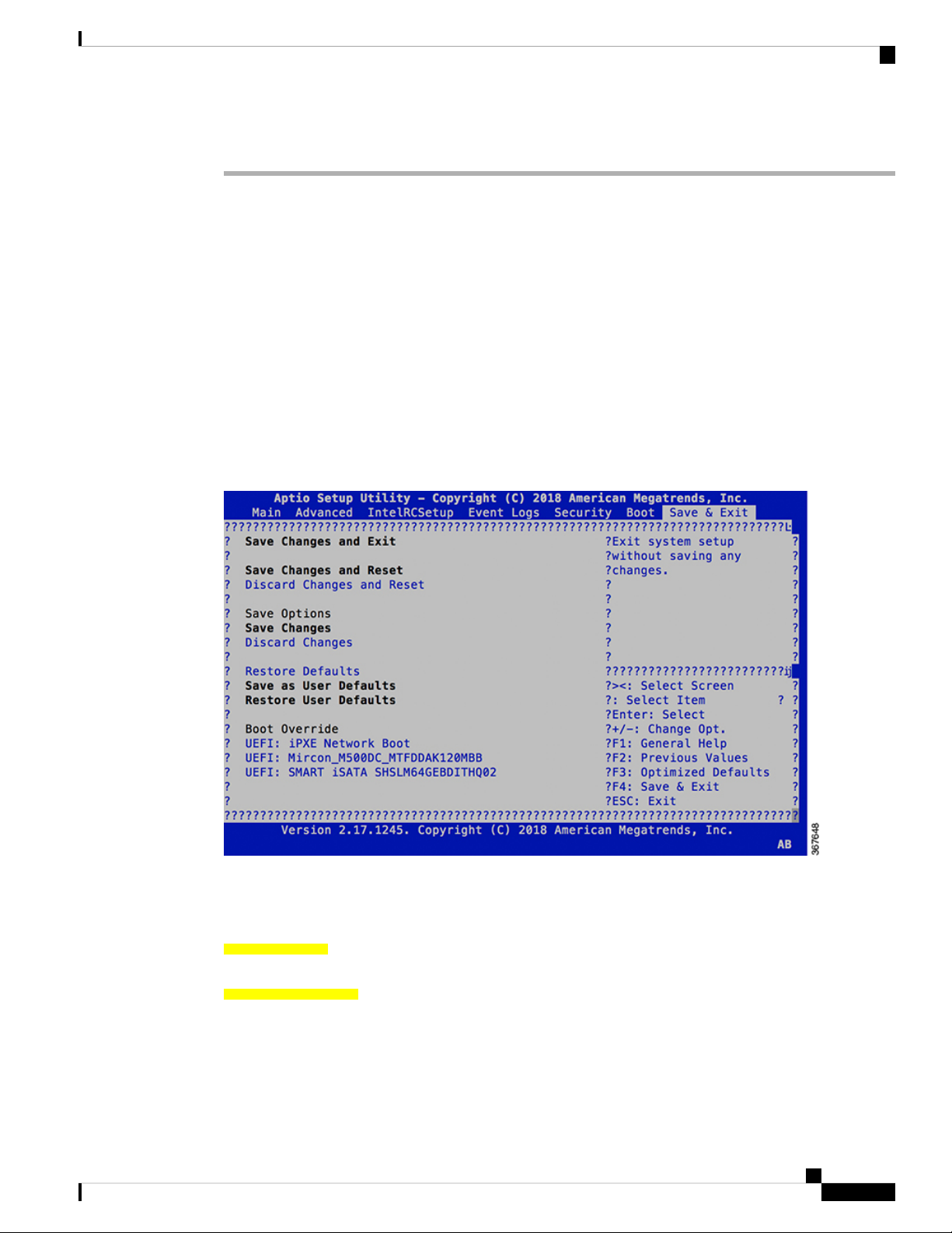
Step 7 Press Esc to enter BIOS.
Step 8 Select the Save & Exit tab of BIOS.
Step 9 Choose UEFI based USB device.
The system detects USB and boots the image from USB.
Admin Console:
GNU GRUB version 2.00
Press F2 to goto grub Menu..
Booting from USB..
Loading Kernel..
Validating End Entity Certificate...
Validating SubCA Certificate...
System Setup and Software Installation Guide for Cisco NCS 1002
5
Page 10

Boot NCS 1002 Using USB Drive
Validating Root Certificate...
Loading initrd..
Validating End Entity Certificate...
Validating SubCA Certificate...
Validating Root Certificate...
CiscoSec: Image signature verification completed.
XR Console:
CiscoSec: Image signature verified.
[ 9.957281] i8042: No controller found
Starting udev
udevd[972]: failed to execute '/etc/udev/scripts/network.sh' '/etc/udev/scripts/network.sh':
No such file or directory
Populating dev cache
Running postinst /etc/rpm-postinsts/100-dnsmasq...
update-rc.d: /etc/init.d/run-postinsts exists during rc.d purge (continuing)
Removing any system startup links for run-postinsts ...
/etc/rcS.d/S99run-postinsts
Configuring network interfaces... done.
Step 10 Remove the USB drive. The NCS 1002 reboots automatically.
Bring-up Cisco NCS 1002
Setting maximal mount count to -1
Setting interval between checks to 0 seconds
Fri Dec 11 20:35:56 UTC 2015: Install EFI on /dev/mb_disk4
Fri Dec 11 20:35:57 UTC 2015: Install finished on mb_disk
Rebooting system after installation ...
[ 116.973666] reboot: Restarting system
Version 2.17.1245. Copyright (C) 2015 American Megatrends, Inc.
BIOS Date: 11/29/2015 12:02:45 Ver: 0ACBZ1110
Press <DEL> or <ESC> to enter setup.
CiscoSec: Image signature verified.
GNU GRUB version 2.00
Press F2 to goto grub Menu..
Booting from Disk..
Loading Kernel..
Validating End Entity Certificate...
Validating SubCA Certificate...
Validating Root Certificate...
Loading initrd..
Validating End Entity Certificate...
Validating SubCA Certificate...
Validating Root Certificate...
CiscoSec: Image signature verification completed.
Initrd, addr=0xff69a000, size=0x955cb0
[ 1.745686] i8042: No controller found
System Setup and Software Installation Guide for Cisco NCS 1002
6
Page 11

Bring-up Cisco NCS 1002
Boot Using iPXE
iPXE is a pre-boot execution environment that is included in the network card of the management interfaces
and works at the system firmware (UEFI) level of the chassis. iPXE is used to re-image the system, and boot
the chassis in case of boot failure or in the absence of a valid bootable partition. iPXE downloads the ISO
image, proceeds with the installation of the image, and finally bootstraps inside the new installation.
iPXE acts as a boot loader and provides the flexibility to choose the image that the system will boot based on
the Platform Identifier (PID), the Serial Number, or the management mac-address. iPXE must be defined in
the DHCP server configuration file.
Setup DHCP Server
A DHCP server must be configured for IPv4, IPv6, or both communication protocols.
Note
For DHCPv6, a routing advertisement (RA) message must be sent to all nodes in the network that indicates
which method is to be used to obtain the IPv6 address. Configure Router-advertise-daemon (radvd, install
using yum install radvd) to allow the client to send the DHCP request. For example:
interface eth3
{
};
Boot Using iPXE
AdvSendAdvert on;
MinRtrAdvInterval 60;
MaxRtrAdvInterval 180;
AdvManagedFlag on;
AdvOtherConfigFlag on;
prefix 2001:1851:c622:1::/64
{
AdvOnLink on;
AdvAutonomous on;
AdvRouterAddr off;
};
To setup a DHCP server:
1. Create the dhcpd.conf file (for IPv4, IPv6 or both communication protocols), dhcpv6.conf file (for IPv6)
or both in the /etc/ directory. This configuration file stores the network information such as the path
to the script, location of the ISO install file, location of the provisioning configuration file, serial number,
MAC address of the chassis.
2. Test the server once the DHCP server is running:
For example, for ipv4:
1. Use MAC address of the chassis:
host ncs1k
{
hardware ethernet ab:cd:ef:01:23:45;
fixed-address <ip address>;
filename "http://<httpserver-address>/<path-to-image>/ncs1k-mini-x.iso";
}
Ensure that the above configuration is successful.
System Setup and Software Installation Guide for Cisco NCS 1002
7
Page 12

Boot Using iPXE
Bring-up Cisco NCS 1002
2. Use serial number of the chassis:
host demo {
option dhcp-client-identifier "<chassis-serial-number>";
filename "http://<IP-address>/<hardware-platform>-mini-x.iso";
fixed-address <IP-address>;
}
The serial number of the chassis is derived from the BIOS and is used as an identifier.
Example
Boot Using iPXE
Before you use the iPXE boot, ensure that:
Run the following command to invoke the iPXE boot process to reimage the chassis:
hw-module location all bootmedia network reload
Example:
sysadmin-vm:0_RP0# hw-module location all bootmedia network reload
Wed Dec 23 15:29:57.376 UTC
Reload hardware module ? [no,yes]
host 10.89.205.202 {
hardware ethernet 40:55:39:56:0c:e8;
if exists user-class and option user-class = "iPXE" {
filename "http://10.89.205.127/box1/ncs1k-mini-x-6.3.1.iso";
} else {
filename "http://10.89.205.127/box1/StartupConfig.cfg";
}
fixed-address 10.89.205.202;
}
• DHCP server is set and is running.
• You have logged in to the System Admin console using the admin command.
The following example shows the output of the command:
iPXE 1.0.0+ (3e573) -- Open Source Network Boot Firmware -- http://ipxe.org
Features: DNS HTTP TFTP VLAN EFI ISO9660 NBI Menu
Trying net0...
net0: c4:72:95:a6:14:e1 using dh8900cc on PCI01:00.1 (open)
[Link:up, TX:0 TXE:0 RX:0 RXE:0]
Configuring (net0 c4:72:95:a6:14:e1).................. Ok << Talking to DHCP/PXE server to
obtain network information
net0: 10.37.1.101/255.255.0.0 gw 10.37.1.0
net0: fe80::c672:95ff:fea6:14e1/64
net0: 2001:1800:5000:1:c672:95ff:fea6:14e1/64 gw fe80::20c:29ff:fefb:b9fe
net1: fe80::c672:95ff:fea6:14e3/64 (inaccessible)
Next server: 10.37.1.235
Filename: http://10.37.1.235/ncs1k/ncs1k-mini-x.iso
http://10.37.1.235/ ... 58% << Downloading file as indicated by DHCP/PXE server to boot
install image
System Setup and Software Installation Guide for Cisco NCS 1002
8
Page 13

Bring-up Cisco NCS 1002
Boot Using ZTP
Zero Touch Provisioning (ZTP) is used to deploy minimal configurations on several chassis. ZTP is used to
boot, set up, and configure the system. Configurations such as configuring the management ethernet interface,
installing SMUs, applications, and optional packages can be automated using ZTP. ZTP does not execute if
a user name is already configured in the system.
ZTP auto provisioning involves:
• Configuration: Downloads and executes the configuration files. The first line of the file must contain
!! IOS XR for ZTP to process the file as a configuration.
• Script: Downloads and executes the script files. These script files include a programmatic approach to
complete a task. For example, scripts created using IOS XR commands to perform patch upgrades. The
first line of the file must contain #! /bin/bash or #! /bin/sh for ZTP to process the file as a script.
The user can either use the ZTP bash script or the ZTP configuration file.
host n1k {
#hardware ethernet 00:a0:c9:00:00:00;
option dhcp-client-identifier "<chassis-serial-number>";
filename "http://<IP-address>/<folder>/ncs1k-ztp.script";
#filename "http://<IP-address>/<folder>/ncs1k-ztp.cfg";
}
Boot Using ZTP
The following is the sample content of the ZTP bash script.
#! /bin/bash
#
# NCS1K Demo Sample
# ZTP installation of config and day-0 SMU's
#
source ztp_helper
wget http://downloads.sourceforge.net/project/yourcode/application.tgz
#install the downloaded application.tgz
#Run XR CLI’s from the script
`xrcmd “show version”`
The following is the sample content of the ZTP configuration file. The user can automate all the configurations
such as configuring the management ethernet interface, slice provisioning, and so on.
!! IOS XR Configuration version = 6.3.2
!
telnet vrf default ipv4 server max-servers 20
!
vty-pool default 0 20 line-template default
!
interface MgmtEth0/RP0/CPU0/0
ipv4 address dhcp
no shutdown
!
router static
address-family ipv4 unicast
0.0.0.0/0 10.77.132.1
!
end
System Setup and Software Installation Guide for Cisco NCS 1002
9
Page 14

Boot NCS 1002 Using Golden ISO
Boot NCS 1002 Using Golden ISO
Golden ISO is a feature provided to user for building customized ISO using mini ISO, required SMUs and
IOS-XR configuration.
Before the introduction of Golden ISO feature, the user must perform the following three steps, to install a
new image.
Step 1 : Boot the system with mini ISO. This can be done using iPXE or USB boot.
Step 2 : Install, add, and activate all the relevant SMUs/optional packages on to NCS 1002. NCS 1002 reloads
on reload of any SMUs.
Step 3 : Apply IOS-XR configuration.
Benefits of Golden ISO
• Saves installation effort and time.
• System gets ready in a single command and single boot.
Bring-up Cisco NCS 1002
Golden ISO feature installs mini ISO image with necessary SMUs and applies IOS-XR configuration.
Golden ISO is built using ‘gisobuild.py’script, which is available at /pkg/bin/gisobuild.py location.
Command to build Golden ISO
The following command is used to build Golden ISO:
/pkg/bin/gisobuild.py -i./ncs1k-mini-x.iso -r ./rpm_directory -c ./xr_config -1 V1
ncs1k-mini-x.iso - mini ISO of NCS 1002.
rpm_directory - Directory where SMUs (xr, calvados and host) are copied.
xr_config - IOS-XR configuration to be applied to system after booting.
V1 - Label of Golden ISO.
Note
Golden ISO needs 6 GB free space to work. If 6 GB free space is not available, user gets the following error
message.
"[xr-vm_node0_RP0_CPU0:/pkg/bin]$gisobuild.py -i/harddisk:/ncs1k-mini-x-6.5.2.26I.iso
-r/misc/disk1/ -1v2
Minimum 6 GB of free disk space is required for building Golden ISO.
Error: 2.35736465454 GB free disk space available in /pkg/bin"
The user must run the script under XR run prompt as follows:
[xr-vm_node0_RP0_CPU0:~]$
[xr-vm_node0_RP0_CPU0:~]$cd /run/
[xr-vm_node0_RP0_CPU0:/run]$gisobuild.py -i /harddisk:/ncs1k-mini-x-6.5.2.26I.iso -r /misc/disk1/ -l v2
System requirements check [PASS]
Golden ISO build process starting...
Platform: ncs1k Version: 6.5.2.26I
System Setup and Software Installation Guide for Cisco NCS 1002
10
Page 15

Bring-up Cisco NCS 1002
Verify Boot Operation
Scanning repository [/misc/disk1]...
Building RPM Database...
Total 1 RPM(s) present in the repository path provided in CLI
[ 1] ncs1k-k9sec-4.1.0.0-r65226I.x86_64.rpm
Following XR x86_64 rpm(s) will be used for building Golden ISO:
(+) ncs1k-k9sec-4.1.0.0-r65226I.x86_64.rpm
...RPM compatibility check [PASS]
Building Golden ISO...
Summary .....
XR rpms:
ncs1k-k9sec-4.1.0.0-r65226I.x86_64.rpm
...Golden ISO creation SUCCESS.
Golden ISO file is created in the following format:
platform-name-golden-x.iso-version.label (does not contain security(*k9sec*.rpm) rpm)
Example: ncs1k-golden-x-7.0.1.14I-V1.iso
platform-name-goldenk9-x.iso-version.label (does contain security(*k9sec*.rpm) rpm)
Example: ncs1k-goldenk9-x-7.0.1.14I-V1.iso
Verify Boot Operation
Procedure
Step 1 After the boot operation, reload the NCS 1002.
Step 2 show version
Example:
RP/0/RP0/CPU0:ios# show version
Wed Aug 8 16:10:20.694 IST
Cisco IOS XR Software, Version 6.5.1
Copyright (c) 2013-2018 by Cisco Systems, Inc.
Build Information:
Built By : ahoang
Built On : Mon Aug 6 14:00:31 PDT 2018
Built Host : iox-ucs-023
Workspace : /auto/srcarchive17/prod/6.5.1/ncs1k/ws
Version : 6.5.1
Location : /opt/cisco/XR/packages/
cisco NCS-1002 () processor
System uptime is 1 day 5 hours 15 minutes
System Setup and Software Installation Guide for Cisco NCS 1002
11
Page 16

Access the System Admin Console
Compare the displayed version with the boot image version. The versions need to be the same.
Access the System Admin Console
All system administration and hardware management setups are performed from the System Admin console.
Procedure
Step 1 Login to the XR console as the root user.
Step 2 admin
Example:
RP/0/RP0/CPU0:ios# admin
Bring-up Cisco NCS 1002
Wed Jul 29 18:05:14.280 UTC
root connected from 127.0.0.1 using console on xr-vm_node0_RP1_CPU0
sysadmin-vm:0_RP0#
After you enter the System Admin console, the prompt changes to:
sysadmin-vm:0_RP0#
Step 3 (Optional) exit
Example:
sysadmin-vm:0_RP0# exit
Wed Jul 29 18:05:15.994 UTC
RP/0/RP0/CPU0:ios#
Return to the XR CLI from the System Admin CLI.
Configure Management Interface
To use the management interface for system management and remote communication, you must configure
an IP address and subnet mask for the management ethernet interface. To communicate with devices on other
networks (such as remote management stations or TFTP servers), you need to configure a default (static) route
for the NCS 1002.
The range of supported MTU of management plane is 64 to 1514 bytes.
Before you begin
• Consult your network administrator or system planner to procure IP addresses and a subnet mask for the
management port.
System Setup and Software Installation Guide for Cisco NCS 1002
12
Page 17

Bring-up Cisco NCS 1002
Step 1 configure
Step 2 interface mgmtEth rack/slot/instance/port
Step 3 ipv4 address ipv4-address subnet-mask
Configure Management Interface
• Ensure that the management port is connected to the management network.
Procedure
Example:
RP/0/RP0/CPU0:ios# configure
Enters XR Configuration mode.
Example:
RP/0/RP0/CPU0:ios(config)# interface mgmtEth 0/RP0/CPU0/0
Enters interface configuration mode for the management interface.
Example:
RP/0/RP0/CPU0:ios(config-if)# ipv4 address 10.1.1.1 255.0.0.0
Assigns an IP address and a subnet mask to the interface.
Step 4 no shutdown
Example:
RP/0/RP0/CPU0:ios(config-if)# no shutdown
Places the interface in an "up" state.
Step 5 exit
Example:
RP/0/RP0/CPU0:ios(config-if)# exit
Exits the Management interface configuration mode.
Step 6 router static address-family ipv4 unicast 0.0.0.0/0default-gateway
Example:
RP/0/RP0/CPU0:ios(config)# router static address-family ipv4 unicast 0.0.0.0/0 12.25.0.1
Specifies the IP address of the default-gateway to configure a static route; this is to be used for communications
with devices on other networks.
Step 7 Use the commit or end command.
commit-Saves the configuration changes and remains within the configuration session.
end-Prompts user to take one of these actions:
• Yes-Saves configuration changes and exits the configuration session.
• No-Exits the configuration session without committing the configuration changes.
System Setup and Software Installation Guide for Cisco NCS 1002
13
Page 18

Configure Telnet
• Cancel-Remains in the configuration session, without committing the configuration changes.
What to do next
Configure Telnet, on page 14 and Configure SSH, on page 15.
Configure Telnet
With a terminal emulation program, establish a telnet session to the management interface port using its IP
address.
Procedure
Step 1 configure
Bring-up Cisco NCS 1002
Example:
RP/0/RP0/CPU0:ios# configure
Enters the Configuration mode.
Step 2 telnet {ipv4 | ipv6} server max-servers limit
Example:
RP/0/RP0/CPU0:ios(config)# telnet ipv4 server max-servers 10
Specifies the number of allowable Telnet servers. Up to 100 Telnet servers are allowed. By default, no Telnet
servers are allowed. You must configure this command to enable the use of Telnet servers.
Step 3 Use the commit or end command.
commit-Saves the configuration changes and remains within the configuration session.
end-Prompts user to take one of these actions:
• Yes-Saves configuration changes and exits the configuration session.
• No-Exits the configuration session without committing the configuration changes.
• Cancel-Remains in the configuration session, without committing the configuration changes.
What to do next
Configure SSH, on page 15
System Setup and Software Installation Guide for Cisco NCS 1002
14
Page 19

Bring-up Cisco NCS 1002
Configure SSH
With a terminal emulation program, establish a SSH connection to the management interface port using its
IP address.
Before you begin
• Install the ncs1k-k9sec package on the NCS 1002. For details about package installation, see Install
Packages, on page 49.
• Generate the crypto key for SSH using the crypto key generate dsa command.
Procedure
Step 1 configure
Example:
RP/0/RP0/CPU0:ios# configure
Configure SSH
Enters the Configuration mode.
Step 2 ssh server v2
Example:
RP/0/RP0/CPU0:ios(config)# ssh server v2
Enables the SSH server to accept only SSHv2 client connections.
Step 3 Use the commit or end command.
commit-Saves the configuration changes and remains within the configuration session.
end-Prompts user to take one of these actions:
• Yes-Saves configuration changes and exits the configuration session.
• No-Exits the configuration session without committing the configuration changes.
• Cancel-Remains in the configuration session, without committing the configuration changes.
Step 4 show ssh session details
Example:
RP/0/RP0/CPU0:ios# show ssh session details
Displays a detailed report of the SSHv2 connections to and from NCS 1002.
What to do next
Perform Clock Synchronization with NTP Server, on page 16
System Setup and Software Installation Guide for Cisco NCS 1002
15
Page 20

Perform Clock Synchronization with NTP Server
Perform Clock Synchronization with NTP Server
There are independent system clocks for the XR and the System Admin. To ensure that these clocks do not
deviate from true time, they need to be synchronized with the clock of a NTP server. In this task you will
configure a NTP server for the XR. After the XR clock is synchronized, the System Admin clock automatically
synchronizes with the XR clock.
Before you begin
Configure and connect to the management port.
Procedure
Step 1 configure
Example:
RP/0/RP0/CPU0:ios# configure
Bring-up Cisco NCS 1002
Enters XR Configuration mode.
Step 2 ntp server server_address
Example:
RP/0/RP0/CPU0:ios# ntp server 64.90.182.55
The XR clock is configured to be synchronized with the specified sever.
System Setup and Software Installation Guide for Cisco NCS 1002
16
Page 21

Perform Preliminary Checks
After successfully logging into the console, you must perform some preliminary checks to verify the default
setup. If any setup issue is detected when these checks are performed, take corrective action before making
further configurations. These preliminary checks are:
• Verify Status of Hardware Components, on page 17
• Verify Node Status, on page 21
• Verify Software Version, on page 23
• Verify Firmware Version, on page 24
• Verify Management Interface Status, on page 27
• Verify Alarms, on page 29
• Verify Environmental Parameters, on page 30
• Verify Inventory, on page 33
Verify Status of Hardware Components
To verify the status of all the hardware components installed on the NCS 1002, perform the following
procedure.
CHAPTER 3
Before you begin
Ensure that all the required hardware components have been installed on the NCS 1002. For installation details,
see Cisco Network Convergence System 1000 Series Hardware Installation Guide.
Procedure
Step 1 show platform
When you execute this command from the Cisco IOS XR EXEC mode, the status of the Cisco IOS XR is
displayed.
Verify that the node state is Operational and admin state is UP.
Example:
RP/0/RP0/CPU0:ios# show platform
Wed Feb 28 03:28:40.004 UTC
Node Type State Config state
System Setup and Software Installation Guide for Cisco NCS 1002
17
Page 22

Verify Status of Hardware Components
-------------------------------------------------------------------------------0/RP0/CPU0 NCS1K-CNTLR(Active) IOS XR RUN NSHUT
a) If the Cisco IOS XR is not operational, no output is shown in the result. In this case, verify the state of
service domain router (SDR) on the node using the show sdr command in Cisco IOS XR mode.
The following example shows sample output from the show sdr command in Cisco IOS XR mode.
RP/0/RP0/CPU0:ios# show sdr
Wed Feb 28 03:28:45.845 UTC
Type NodeName NodeState RedState PartnerName
-------------------------------------------------------------------------------RP 0/RP0/CPU0 IOS XR RUN ACTIVE NONE
NCS1K-CNTLR 0/RP0 OPERATIONAL N/A
Step 2 admin
Enters System Admin EXEC mode.
Example:
RP/0/RP0/CPU0:ios# admin
Perform Preliminary Checks
Step 3 show platform
Displays information and status for each node in the system.
Example:
sysadmin-vm:0_RP0# show platform
Wed Feb 28 03:31:53.672 UTC
Location Card Type HW State SW State Config State
---------------------------------------------------------------------------0/0 NCS1002-K9 OPERATIONAL N/A NSHUT
0/RP0 NCS1K-CNTLR OPERATIONAL OPERATIONAL NSHUT
0/FT0 NCS1K-FTA OPERATIONAL N/A NSHUT
0/FT1 NCS1K-FTA OPERATIONAL N/A NSHUT
0/FT2 NCS1K-FTA OPERATIONAL N/A NSHUT
Verify that all components of the NCS 1002 are displayed in the result. The software state and the hardware
state must be in the OPERATIONAL state. The various hardware and software states are:
Hardware states:
• OPERATIONAL—Node is operating normally and is fully functional.
• POWERED_ON—Power is on and the node is booting up.
• FAILED—Node is powered on but has experienced some internal failure.
• PRESENT—Node is in the shutdown state.
• OFFLINE—User has changed the node state to OFFLINE. The node is accessible for diagnostics.
Software states:
• OPERATIONAL—Software is operating normally and is fully functional.
• SW_INACTIVE—Software is not completely operational.
• FAILED—Software is operational but the card has experienced some internal failure.
System Setup and Software Installation Guide for Cisco NCS 1002
18
Page 23

Perform Preliminary Checks
Step 4 show platform detail
Verify Status of Hardware Components
Displays the hardware and software states, and other details of the node.
Example:
sysadmin-vm:0_RP0# show platform detail
Wed Feb 28 03:33:14.557 UTC
Platform Information for 0/0
PID : NCS1002-K9
Description : "Network Convergence System 1002 20 QSFP28/QSFP+ slots"
VID/SN : V01
HW Oper State : OPERATIONAL
SW Oper State : N/A
Configuration : "NSHUT RST"
HW Version : 0.1
Last Event : HW_EVENT_OK
Last Event Reason : "HW Event OK"
Platform Information for 0/RP0
PID : NCS1K-CNTLR
Description : "Network Convergence System 1000 Controller"
VID/SN : V03
HW Oper State : OPERATIONAL
SW Oper State : OPERATIONAL
Configuration : "NSHUT RST"
HW Version : 0.1
Last Event : HW_EVENT_OK
Last Event Reason : "HW Event OK"
Platform Information for 0/FT0
PID : NCS1K-FTA
Description : "Network Convergence System 1000 Fan"
VID/SN : V01
HW Oper State : OPERATIONAL
SW Oper State : N/A
Configuration : "NSHUT RST"
HW Version : 0.1
Last Event : HW_EVENT_OK
Last Event Reason : "HW Operational"
Platform Information for 0/FT1
PID : NCS1K-FTA
Description : "Network Convergence System 1000 Fan"
VID/SN : V01
HW Oper State : OPERATIONAL
SW Oper State : N/A
Configuration : "NSHUT RST"
HW Version : 0.1
Last Event : HW_EVENT_OK
Last Event Reason : "HW Operational"
Platform Information for 0/FT2
PID : NCS1K-FTA
Description : "Network Convergence System 1000 Fan"
VID/SN : V01
HW Oper State : OPERATIONAL
SW Oper State : N/A
Configuration : "NSHUT RST"
HW Version : 0.1
Last Event : HW_EVENT_OK
Last Event Reason : "HW Operational"
Step 5 show inventory
System Setup and Software Installation Guide for Cisco NCS 1002
19
Page 24

Verify Status of Hardware Components
Displays the details of the physical entities of the NCS 1002 along with the details of QSFPs and CFPs when
you execute this command in the Cisco IOS XR EXEC mode.
Example:
RP/0/RP0/CPU0:ios# show inventory
Fri May 18 10:46:51.323 UTC
NAME: "0/0", DESCR: "Network Convergence System 1002 20 QSFP28/QSFP+ slots"
PID: NCS1002-K9 , VID: V03, SN: CAT2116B170
NAME: "0/0-Optics0/0/0/1", DESCR: "Non-Cisco QSFP28 100G LR4 Pluggable Optics Module"
PID: SPQCELRCDFB , VID: 01 , SN: G9I2011804
NAME: "0/0-Optics0/0/0/4", DESCR: "Non-Cisco QSFP28 100G LR4 Pluggable Optics Module"
PID: TR-FC13L-N00 , VID: 01 , SN: INGAJ0930306
NAME: "0/0-Optics0/0/0/6", DESCR: "Cisco CFP2 DWDM Pluggable Optics"
PID: ONS-CFP2-WDM , VID: V01 , SN: OUK1936006S
NAME: "0/0-Optics0/0/0/7", DESCR: "Cisco 4x10GE QSFP+ LR-S Pluggable Optics Module"
PID: QSFP-4X10G-LR-S , VID: V02 , SN: INL20410069
NAME: "0/0-Optics0/0/0/8-LANE1", DESCR: "Cisco 10G SFP LR Pluggable Optics Module"
PID: SFP-10G-LR , VID: V01 , SN: SPC1907074R
Perform Preliminary Checks
NAME: "0/0-Optics0/0/0/9", DESCR: "Cisco 40GE QSFP+ SR4 Pluggable Optics Module"
PID: QSFP-40G-SR4 , VID: V03 , SN: JFQ20332088
NAME: "0/0-Optics0/0/0/10", DESCR: "Non-Cisco QSFP28 100G LR4 Pluggable Optics Module"
PID: SPQCELRCDFB , VID: 01 , SN: GAV2008935
NAME: "0/0-Optics0/0/0/11-LANE1", DESCR: "Cisco 10G SFP LR Pluggable Optics Module"
PID: SFP-10G-LR , VID: V01 , SN: SPC190707YP
NAME: "0/0-Optics0/0/0/17-LANE1", DESCR: "Cisco 10G SFP SR Pluggable Optics Module"
PID: SFP-10G-SR , VID: V03 , SN: JUR1904073P
NAME: "0/0-Optics0/0/0/18", DESCR: "Non-Cisco QSFP28 100G LR4 Pluggable Optics Module"
PID: FTLC1151RDPL , VID: A0 , SN: UVE1C6C
NAME: "0/0-Optics0/0/0/19", DESCR: "Cisco CFP2 DWDM Pluggable Optics"
PID: ONS-CFP2-WDM , VID: V05 , SN: OVE204404PA
NAME: "0/0-Optics0/0/0/21", DESCR: "Cisco 4x10GE QSFP+ LR-S Pluggable Optics Module"
PID: QSFP-4x10G-LR-S , VID: V01 , SN: INL20200012
NAME: "0/0-Optics0/0/0/22-LANE1", DESCR: "Cisco 10G SFP LR Pluggable Optics Module"
PID: SFP-10G-LR , VID: V01 , SN: SPC190707YS
NAME: "0/0-Optics0/0/0/23", DESCR: "Cisco 40GE QSFP+ SR4 Pluggable Optics Module"
PID: QSFP-40G-SR4 , VID: V03 , SN: JFQ2033201H
NAME: "0/0-Optics0/0/0/24", DESCR: "Non-Cisco QSFP28 100G LR4 Pluggable Optics Module"
PID: FTLC1151RDPL , VID: A0 , SN: UWD2QMM
NAME: "0/0-Optics0/0/0/25-LANE1", DESCR: "Cisco 10G SFP ER Pluggable Optics Module"
PID: SFP-10G-ER , VID: V02 , SN: ONT213100BW
NAME: "0/RP0", DESCR: "Network Convergence System 1000 Controller"
PID: NCS1K-CNTLR , VID: V04, SN: CAT2052B0FZ
NAME: "Rack 0", DESCR: "Network Convergence System 1002 20 QSFP28/QSFP+ slots"
PID: NCS1002-K9 , VID: V03, SN: CAT2116B170
System Setup and Software Installation Guide for Cisco NCS 1002
20
Page 25

Perform Preliminary Checks
NAME: "0/FT0", DESCR: "Network Convergence System 1000 Fan"
PID: NCS1K-FTA , VID: V01, SN: N/A
NAME: "0/FT1", DESCR: "Network Convergence System 1000 Fan"
PID: NCS1K-FTA , VID: V01, SN: N/A
NAME: "0/FT2", DESCR: "Network Convergence System 1000 Fan"
PID: NCS1K-FTA , VID: V01, SN: N/A
NAME: "0/PM0", DESCR: "Network Convergence System 1000 2KW AC PSU"
PID: NCS1K-2KW-AC , VID: V01, SN: POG2041J0BW
NAME: "0/PM1", DESCR: "Network Convergence System 1000 2KW AC PSU"
PID: NCS1K-2KW-AC , VID: V01, SN: POG2041J01C
You can verify if any QSFP or CFP has been removed from the NCS 1002.
Verify Node Status
Verify Node Status
You can verify the operational status of all the nodes using the show platform command. You can execute
this command independently from both the Cisco IOS XR EXEC and System Admin EXEC modes.
To verify the operational status of all the nodes, perform the following procedure.
Procedure
Step 1 show platform
When you execute this command from the XR EXEC mode, the status of the Cisco IOS XR is displayed.
Verify that the node state is Operational and admin state is UP.
Example:
RP/0/RP0/CPU0:ios# show platform
Wed Feb 28 03:28:40.004 UTC
Node Type State Config state
-------------------------------------------------------------------------------0/RP0/CPU0 NCS1K-CNTLR(Active) IOS XR RUN NSHUT
If the Cisco IOS XR is not operational, no output is shown in the result. In this case, verify the state of SDR
on the node using the show sdr command in the System Admin EXEC mode.
Step 2 admin
Enters System Admin EXEC mode.
Example:
RP/0/RP0/CPU0:ios# admin
Step 3 show platform
Displays information and status for each node in the system.
Example:
System Setup and Software Installation Guide for Cisco NCS 1002
21
Page 26

Verify Node Status
Perform Preliminary Checks
sysadmin-vm:0_RP0# show platform
Wed Feb 28 03:31:53.672 UTC
Location Card Type HW State SW State Config State
---------------------------------------------------------------------------0/0 NCS1002-K9 OPERATIONAL N/A NSHUT
0/RP0 NCS1K-CNTLR OPERATIONAL OPERATIONAL NSHUT
0/FT0 NCS1K-FTA OPERATIONAL N/A NSHUT
0/FT1 NCS1K-FTA OPERATIONAL N/A NSHUT
0/FT2 NCS1K-FTA OPERATIONAL N/A NSHUT
Verify that all the modules of the NCS 1002 are displayed in the result. The software state and the hardware
state must be in the OPERATIONAL state. The various hardware and software states are:
Hardware states:
• OPERATIONAL—Node is operating normally and is fully functional.
• POWERED_ON—Power is on and the node is booting up.
• FAILED—Node is powered on but has experienced some internal failure.
• PRESENT—Node is in the shutdown state.
• OFFLINE—User has changed the node state to OFFLINE. The node is accessible for diagnostics.
Software states:
• OPERATIONAL—Software is operating normally and is fully functional.
• DIAG_MODE—User has changed the card state to OFFLINE for diagnosis.
• SW_INACTIVE—Software is not completely operational.
• FAILED—Software is operational but the card has experienced some internal failure.
Step 4 show platform detail
Displays the hardware and software states, and other details of the node.
Example:
sysadmin-vm:0_RP0# show platform detail
Wed Feb 28 03:33:14.557 UTC
Platform Information for 0/0
PID : NCS1002-K9
Description : "Network Convergence System 1002 20 QSFP28/QSFP+ slots"
VID/SN : V01
HW Oper State : OPERATIONAL
SW Oper State : N/A
Configuration : "NSHUT RST"
HW Version : 0.1
Last Event : HW_EVENT_OK
Last Event Reason : "HW Event OK"
Platform Information for 0/RP0
PID : NCS1K-CNTLR
Description : "Network Convergence System 1000 Controller"
VID/SN : V03
HW Oper State : OPERATIONAL
SW Oper State : OPERATIONAL
Configuration : "NSHUT RST"
HW Version : 0.1
Last Event : HW_EVENT_OK
System Setup and Software Installation Guide for Cisco NCS 1002
22
Page 27

Perform Preliminary Checks
Verify Software Version
Last Event Reason : "HW Event OK"
Platform Information for 0/FT0
PID : NCS1K-FTA
Description : "Network Convergence System 1000 Fan"
VID/SN : V01
HW Oper State : OPERATIONAL
SW Oper State : N/A
Configuration : "NSHUT RST"
HW Version : 0.1
Last Event : HW_EVENT_OK
Last Event Reason : "HW Operational"
Platform Information for 0/FT1
PID : NCS1K-FTA
Description : "Network Convergence System 1000 Fan"
VID/SN : V01
HW Oper State : OPERATIONAL
SW Oper State : N/A
Configuration : "NSHUT RST"
HW Version : 0.1
Last Event : HW_EVENT_OK
Last Event Reason : "HW Operational"
Platform Information for 0/FT2
PID : NCS1K-FTA
Description : "Network Convergence System 1000 Fan"
VID/SN : V01
HW Oper State : OPERATIONAL
SW Oper State : N/A
Configuration : "NSHUT RST"
HW Version : 0.1
Last Event : HW_EVENT_OK
Last Event Reason : "HW Operational"
Verify Software Version
The NCS 1002 is shipped with the Cisco IOS XR software pre-installed. Verify that the latest version of the
software is installed. If a newer version is available, perform a system upgrade. This will install the newer
version of the software and provide the latest feature set on the NCS 1002.
To verify the version of Cisco IOS XR software running on the NCS 1002, perform the following procedure.
Procedure
show version
Displays the software version and details such as system uptime.
Example:
RP/0/RP0/CPU0:ios# show version
Wed Aug 8 16:10:20.694 IST
Cisco IOS XR Software, Version 6.5.1
Copyright (c) 2013-2018 by Cisco Systems, Inc.
Build Information:
System Setup and Software Installation Guide for Cisco NCS 1002
23
Page 28

Verify Firmware Version
Built By : ahoang
Built On : Mon Aug 6 14:00:31 PDT 2018
Built Host : iox-ucs-023
Workspace : /auto/srcarchive17/prod/6.5.1/ncs1k/ws
Version : 6.5.1
Location : /opt/cisco/XR/packages/
cisco NCS-1002 () processor
System uptime is 1 day 5 hours 15 minutes
What to do next
Verify the result to ascertain whether a system upgrade is required. If the upgrade is required, see the Perform
System Upgrade and Install Feature Packages, on page 47 chapter.
Verify Firmware Version
The firmware on various hardware components of the NCS 1002 must be compatible with the installed Cisco
IOS XR image. Incompatibility may cause the NCS 1002 to malfunction.
Perform Preliminary Checks
To verify the firmware version, perform the following procedure.
Procedure
Step 1 show hw-module fpd
Thu Mar 29 15:41:51.520 IST
Location Card type HWver FPD device ATR Status Running Programd
-----------------------------------------------------------------------------0/0 NCS1002-K9 1.2 CDSP_PORT_05 CURRENT 3.77 3.77
0/0 NCS1002-K9 1.2 CDSP_PORT_06 CURRENT 3.77 3.77
0/0 NCS1002-K9 1.2 CDSP_PORT_12 CURRENT 3.77 3.77
0/0 NCS1002-K9 1.2 CDSP_PORT_13 CURRENT 3.77 3.77
0/0 NCS1002-K9 1.2 CDSP_PORT_19 CURRENT 3.77 3.77
0/0 NCS1002-K9 1.2 CDSP_PORT_20 CURRENT 3.77 3.77
0/0 NCS1002-K9 1.2 CDSP_PORT_26 CURRENT 3.77 3.77
0/0 NCS1002-K9 1.2 CDSP_PORT_27 CURRENT 3.77 3.77
0/0 NCS1002-K9 2.1 CFP2_PORT_05 CURRENT 5.52 5.52
0/0 NCS1002-K9 2.1 CFP2_PORT_06 CURRENT 5.52 5.52
0/0 NCS1002-K9 2.1 CFP2_PORT_12 CURRENT 5.52 5.52
0/0 NCS1002-K9 4.2 CFP2_PORT_13 CURRENT 5.52 5.52
0/0 NCS1002-K9 2.1 CFP2_PORT_19 CURRENT 5.52 5.52
0/0 NCS1002-K9 2.1 CFP2_PORT_20 CURRENT 5.52 5.52
0/0 NCS1002-K9 2.1 CFP2_PORT_26 CURRENT 5.52 5.52
0/0 NCS1002-K9 2.1 CFP2_PORT_27 CURRENT 5.52 5.52
0/0 NCS1002-K9 0.1 CTRL_BKP_LOW B CURRENT 2.23
0/0 NCS1002-K9 0.1 CTRL_BKP_UP B CURRENT 2.23
0/0 NCS1002-K9 0.1 CTRL_FPGA_LOW CURRENT 2.23 2.23
0/0 NCS1002-K9 0.1 CTRL_FPGA_UP CURRENT 2.23 2.23
0/RP0 NCS1K-CNTLR 0.1 BIOS_Backup BS CURRENT 14.00
0/RP0 NCS1K-CNTLR 0.1 BIOS_Primary S CURRENT 14.40 14.40
0/RP0 NCS1K-CNTLR 0.1 Daisy_Duke_BKP BS CURRENT 0.15
0/RP0 NCS1K-CNTLR 0.1 Daisy_Duke_FPGA S CURRENT 0.17 0.17
FPD Versions
=================
System Setup and Software Installation Guide for Cisco NCS 1002
24
Page 29

Perform Preliminary Checks
Verify Firmware Version
0/PM0 NCS1K-2KW-AC 0.0 PO-PriMCU CURRENT 4.00 4.00
0/PM1 NCS1K-2KW-AC 0.0 PO-PriMCU CURRENT 4.00 4.00
Displays the firmware information of various hardware components of the NCS 1002 in the Cisco IOS XR
EXEC mode.
In the above output, some of the significant fields are:
• FPD Device—Name of the hardware component such as FPD, CFP, and so on.
• ATR—Attribute of the hardware component. Some of the attributes are:
• B—Backup Image
• S—Secure Image
• P—Protected Image
• Status— Upgrade status of the firmware. The different states are:
• CURRENT—The firmware version is the latest version.
• READY—The firmware of the FPD is ready for an upgrade.
• NOT READY—The firmware of the FPD is not ready for an upgrade.
• NEED UPGD—A newer firmware version is available in the installed image. It is recommended
that an upgrade be performed.
• RLOAD REQ—The upgrade has been completed, and the ISO image requires a reload.
• UPGD DONE—The firmware upgrade is successful.
• UPGD FAIL— The firmware upgrade has failed.
• BACK IMG—The firmware is corrupted. Reinstall the firmware.
• UPGD SKIP—The upgrade has been skipped because the installed firmware version is higher than
the one available in the image.
• Running—Current version of the firmware running on the FPD.
Step 2 show hw-module slice slice_number
Displays the slice and Datapath FPGA (DP-FPGA) information of the NCS 1002.
Example:
RP/0/RP0/CPU0:ios# show hw-module slice 0
Wed Feb 28 04:01:45.828 UTC
Slice ID: 0
Status: Provisioned
Client Bitrate: 10
Trunk Bitrate: 100
DP FPGA FW Type: XMG1
DP FPGA FW Version: 01.01
HW Status: CURRENT
Encryption Supported: FALSE
LLDP Drop Enabled: FALSE
Client Port - Trunk Port CoherentDSP0/0/0/5 CoherentDSP0/0/0/6
Traffic Split Percentage
System Setup and Software Installation Guide for Cisco NCS 1002
25
Page 30

Verify Firmware Version
Perform Preliminary Checks
TenGigECtrlr0/0/0/0/1 100 0
TenGigECtrlr0/0/0/0/2 100 0
TenGigECtrlr0/0/0/0/3 100 0
TenGigECtrlr0/0/0/0/4 100 0
TenGigECtrlr0/0/0/1/1 100 0
TenGigECtrlr0/0/0/1/2 100 0
TenGigECtrlr0/0/0/1/3 100 0
TenGigECtrlr0/0/0/1/4 100 0
TenGigECtrlr0/0/0/2/1 0 100
TenGigECtrlr0/0/0/2/2 0 100
TenGigECtrlr0/0/0/2/3 100 0
TenGigECtrlr0/0/0/2/4 100 0
TenGigECtrlr0/0/0/3/1 0 100
TenGigECtrlr0/0/0/3/2 0 100
TenGigECtrlr0/0/0/3/3 0 100
TenGigECtrlr0/0/0/3/4 0 100
TenGigECtrlr0/0/0/4/1 0 100
TenGigECtrlr0/0/0/4/2 0 100
TenGigECtrlr0/0/0/4/3 0 100
TenGigECtrlr0/0/0/4/4 0 100
In the above output, DP FPGA Version indicates the image of the datapath FPGA. Here, F-203 is the image
version of the 40 G image. The CURRENT value of the HW Status parameter indicates that the firmware
version is the latest.
When the DP FPGA Version is T, it indicates 10 G. If the DP FPGA Version is H, it indicates 100 G image
versions. If Need UPG appears in the output, you must upgrade the slice to get the updated DP FPGA using
the upgrade hw-module slice slice_number re-provision command.
What to do next
Upgrading the Firmware Version of Hardware Components
Notes for Release 6.0.1
• You can upgrade the firmware version of the power modules, BIOS, CFP2, or Coherent DSP of the NCS
1002. For details on upgrading the firmware version of the power modules, see Upgrading the Firmware
Version of Power Modules, on page 58
• You can upgrade both BIOS_Primary and BIOS_Backup.
• You can upgrade the BIOS_Backup only if the Programmed FPD version of the Daisy Duke FPGA is
0.15. If the FPD version of the Daisy Duke FPGA is not 0.15, the state of the BIOS_Backup is NOT
READY state.
Use this procedure to upgrade BIOS_Backup.
1. Upgrade Daisy Duke FPGA.
2. Use the reload command to activate Daisy Duke FPGA.
3. Use the upgrade command to upgrade BIOS_Backup separately.
Use the show fpd package command to display the FPD image version available with this software release
for each hardware component.
sysadmin-vm:0_RP0# show fpd package
Wed Feb 28 03:35:19.382 UTC
System Setup and Software Installation Guide for Cisco NCS 1002
26
Page 31

Perform Preliminary Checks
Verify Management Interface Status
=============================== ================================================
================================================
Card Type FPD Description Reload Ver SW Ver Board Ver
=================== ========================== ====== ======= ======== =========
NCS1002 CTRL_BKP_LOW YES 2.23 2.23 0.1
CTRL_FPGA_LOW YES 2.23 2.23 0.1
-------------------------------------------------------------------------------NCS1002 CTRL_BKP_UP YES 2.23 2.23 0.1
CTRL_FPGA_UP YES 2.23 2.23 0.1
NCS1002--RP BIOS_Backup YES 14.00 14.00 0.1
BIOS_Primary YES 14.00 14.00 0.1
Daisy_Duke_BKP YES 0.15 0.15 0.1
Daisy_Duke_FPGA YES 0.17 0.17 0.1
--------------------------------------------------------------------------------
Field Programmable Device Package
Req SW Min Req Min Req
Upgrade all the FPDs using the upgrade hw-module location all fpd all command in the Cisco IOS XR
EXEC mode. After an upgrade is completed, the Status column shows RLOAD REQ if the software requires
reload.
If Reload is Required
If the FPGA location is 0/RP0, use the admin hw-module location 0/RP0 reload command. This command
reboots only the CPU. As a result, traffic is not impacted. If the FPGA location is 0/0, use the admin hw-module
location all reload command. This command reboots the chassis. As a result, traffic is impacted. After the
reload is completed, the new FPGA runs the current version.
If Firmware Upgrade Fails
If the firmware upgrade fails, use the show logging command to view the details and upgrade the firmware
again using the above commands.
Notes for Release 6.1.2
NCS 1002 uses signed images from R6.1.2. Hence, the firmware must be upgraded to identify the signed
images. When the user needs to use the MACsec feature and upgrades from R6.0.1 to 6.1.2, the control FPGA
(CTRL_BKP_UP, CTRL_BKP_LOW, CTRL_FPGA_UP, and CTRL_FPGA_LOW) must be upgraded to
the latest firmware version provided by R6.1.2.
Verify Management Interface Status
To verify the management interface status, perform the following procedure.
Procedure
show interfaces mgmtEth instance
Displays the management interface configuration.
Example:
RP/0/RP0/CPU0:ios# show interfaces MgmtEth 0/RP0/CPU0/0
Wed Feb 28 03:30:35.525 UTC
MgmtEth0/RP0/CPU0/0 is up, line protocol is up
Interface state transitions: 1
Hardware is Management Ethernet, address is 501c.bf10.9fc0 (bia 501c.bf10.9fc0)
System Setup and Software Installation Guide for Cisco NCS 1002
27
Page 32

Verify Management Interface Status
Internet address is 10.77.132.68/24
MTU 1514 bytes, BW 100000 Kbit (Max: 100000 Kbit)
reliability 255/255, txload 0/255, rxload 0/255
Encapsulation ARPA,
Full-duplex, 100Mb/s, CX, link type is autonegotiation
loopback not set,
Last link flapped 1d21h
ARP type ARPA, ARP timeout 04:00:00
Last input 00:00:00, output 00:02:38
Last clearing of "show interface" counters never
5 minute input rate 2000 bits/sec, 4 packets/sec
5 minute output rate 0 bits/sec, 0 packets/sec
852455 packets input, 58601651 bytes, 0 total input drops
0 drops for unrecognized upper-level protocol
Received 560680 broadcast packets, 290268 multicast packets
0 input errors, 0 CRC, 0 frame, 0 overrun, 0 ignored, 0 abort
1561 packets output, 93270 bytes, 0 total output drops
Output 0 broadcast packets, 0 multicast packets
0 output errors, 0 underruns, 0 applique, 0 resets
0 output buffer failures, 0 output buffers swapped out
1 carrier transitions
In the above result, the management interface is administratively down.
Perform Preliminary Checks
0 runts, 0 giants, 0 throttles, 0 parity
You can also use the show interfaces summary and show interfaces brief commands in the Cisco IOS XR
EXEC mode to verify the management interface status.
• The following example shows sample output from the show interfaces summary command.
RP/0/RP0/CPU0:ios# show interfaces summary
Wed Feb 28 03:30:41.991 UTC
Interface Type Total UP Down Admin Down
-------------- ----- -- ---- ---------ALL TYPES 4 2 0 2
-------------IFT_ETHERNET 3 1 0 2
IFT_NULL 1 1 0 0
• The following example shows sample output from the show interfaces brief command.
RP/0/RP0/CPU0:ios# show interfaces brief
Wed Feb 28 03:30:47.996 UTC
Intf Intf LineP Encap MTU BW
--------------------------------------------------------------------------------
Mg0/RP0/CPU0/0 up up ARPA 1514 100000
Mg0/RP0/CPU0/1 admin-down admin-down ARPA 1514 1000000
Mg0/RP0/CPU0/2 admin-down admin-down ARPA 1514 1000000
Name State State Type (byte) (Kbps)
Nu0 up up Null 1500 0
What to do next
If the management interface is administratively down, perform the following steps:
• Check the Ethernet cable connection.
• Verify the IP configuration of the management interface. For details on configuring the management
interface, see the Bring-up NCS 1002 chapter.
System Setup and Software Installation Guide for Cisco NCS 1002
28
Page 33

Perform Preliminary Checks
Verify Alarms
You can view the alarm information using the show alarms command.
Procedure
Verify Alarms
• Verify whether the management interface is in the no shut state using the show running-config interface
mgmtEth command.
The following example shows sample output from the show running-config interface mgmtEth
command.
RP/0/RP0/CPU0:ios#show running-config interface mgmtEth 0/RP0/CPU0/0
Fri Nov 13 19:42:54.368 UTC
interface MgmtEth0/RP0/CPU0/0
ipv4 address 10.58.227.183 255.255.255.0
!
In the above output, the management interface is in the no shut state.
show alarms [ brief [ card | rack | system ] [ location location ] [ active | history ] | detail
[ card | rack | system ] [ location location ] [ active | clients | history | stats ] ]
Displays alarms in brief or detail.
Example:
RP/0/RP0/CPU0:ios# show alarms brief card location 0/RP0/CPU0 active
Thu Mar 8 17:51:47.237 UTC
-----------------------------------------------------------------------------------Active Alarms
-----------------------------------------------------------------------------------Location Severity Group Set Time Description
-----------------------------------------------------------------------------------0/0 Minor Slice 03/07/2018 07:33:43 UTC Encrypted Slice
Is Provisioned Without K9sec Package Or K9sec Package Incomplete
0/0 Critical Controller 03/07/2018 07:37:19 UTC Optics0/0/0/10 Improper Removal
0/0 Critical Controller 03/07/2018 07:38:17 UTC Optics0/0/0/2 Improper Removal
0/0 Critical Controller 03/07/2018 07:38:17 UTC Optics0/0/0/3 Improper Removal
0/0 Major Ethernet 03/07/2018 08:36:11 UTC
HundredGigECtrlr0/0/0/11 - Remote Fault
System Setup and Software Installation Guide for Cisco NCS 1002
29
Page 34

Verify Environmental Parameters
0/0 Critical Controller 03/07/2018 08:39:27 UTC Optics0/0/0/24 Improper Removal
0/0 Major Ethernet 03/07/2018 08:39:28 UTC
HundredGigECtrlr0/0/0/25 - Remote Fault
0/0 Critical Controller 03/07/2018 08:40:40 UTC Optics0/0/0/16 Improper Removal
0/0 Critical Controller 03/07/2018 08:40:40 UTC Optics0/0/0/17 Improper Removal
0/0 Major Ethernet 03/07/2018 08:40:51 UTC
TenGigECtrlr0/0/0/18/4 - Remote Fault
0/0 Major Ethernet 03/07/2018 08:36:14 UTC TenGigECtrlr0/0/0/4/2
- Remote Fault
Perform Preliminary Checks
0/0 Major Ethernet 03/07/2018 20:37:16 UTC
TenGigECtrlr0/0/0/18/2 - Remote Fault
0/0 Major Ethernet 03/07/2018 08:36:12 UTC TenGigECtrlr0/0/0/4/4
- Remote Fault
0/0 Major Ethernet 03/08/2018 17:51:34 UTC TenGigECtrlr0/0/0/4/3
- Loss of Synchronization The Data Interface
0/0 Major Ethernet 03/08/2018 17:51:34 UTC
TenGigECtrlr0/0/0/18/3 - Loss of Synchronization The Data Interface
0/0 Major Ethernet 03/07/2018 08:36:12 UTC TenGigECtrlr0/0/0/4/1
- Remote Fault
0/0 Major Ethernet 03/07/2018 08:40:50 UTC
TenGigECtrlr0/0/0/18/1 - Remote Fault
What to do next
For more information about alarms and steps to clear them, see the Alarm Troubleshooting chapter of the
Cisco NCS 1000 Series Troubleshooting Guide.
Verify Environmental Parameters
The show environment command displays the environmental parameters of the NCS 1002.
System Setup and Software Installation Guide for Cisco NCS 1002
30
Page 35

Perform Preliminary Checks
Step 1 admin
Step 2 show environment [ all | fan | power | voltages | current | temperatures ] [ location
Verify Environmental Parameters
To verify that the environmental parameters are as expected, perform the following procedure.
Procedure
Enters System Admin EXEC mode.
Example:
RP/0/RP0/CPU0:ios# admin
| location ]
Displays the environmental parameters of the NCS 1002.
Example:
The following example shows sample output from the show environment command with the fan keyword.
sysadmin-vm:0_RP0# show environment fan
Wed Feb 28 03:34:08.625 UTC
=====================================
Fan speed (rpm)
Location FRU Type FAN_0
------------------------------------0/FT0 NCS1K-FTA 5400
0/FT1 NCS1K-FTA 5340
0/FT2 NCS1K-FTA 5460
0/PM0 NCS1K-2KW-AC 0
0/PM1 NCS1K-2KW-AC 9664
The following example shows sample output from the show environment command with the temperatures
keyword.
sysadmin-vm:0_RP0# show environment temperatures location 0/RP0
Wed Feb 28 03:34:16.110 UTC
================================================================================
Location TEMPERATURE Value Crit Major Minor Minor Major Crit
-------------------------------------------------------------------------------0/RP0
Sensor (deg C) (Lo) (Lo) (Lo) (Hi) (Hi) (Hi)
Thermistor 1 32 -10 0 0 55 55 85
Thermistor 2 32 -10 0 0 55 55 85
Hot Spot Temperature 31 -10 0 0 55 55 85
The following example shows sample output from the show environment command with the power keyword.
sysadmin-vm:0_RP0# show environment power
Wed Feb 28 03:34:28.920 UTC
================================================================================
CHASSIS LEVEL POWER INFO: 0
================================================================================
Total output power capacity (N + 1) : 2000W + 0W
Total output power required : 975W
Total power input : 272W
Total power output : 227W
Power Group 0:
================================================================================
Power Supply ------Input---- ------Output--- Status
System Setup and Software Installation Guide for Cisco NCS 1002
31
Page 36

Verify Environmental Parameters
Module Type Volts Amps Volts Amps
================================================================================
0/PM0 2kW-AC 0.0 0.0 12.0 0.0 FAILED or NO PWR
Total of Power Group 0: 0W/ 0.0A 0W/ 0.0A
Power Group 1:
================================================================================
Power Supply ------Input---- ------Output--- Status
Module Type Volts Amps Volts Amps
================================================================================
0/PM1 2kW-AC 226.5 1.2 12.0 18.9 OK
Total of Power Group 1: 272W/ 1.2A 227W/ 18.9A
================================================================================
Location Card Type Power Power Status
================================================================================
0/0 NCS1002-K9 820 - ON
0/RP0 NCS1K-CNTLR 35 - ON
0/FT0 NCS1K-FTA 40 - ON
0/FT1 NCS1K-FTA 40 - ON
0/FT2 NCS1K-FTA 40 - ON
Perform Preliminary Checks
Allocated Used
Watts Watts
The following example shows sample output from the show environment command with the voltages
keyword.
sysadmin-vm:0_RP0# show environment voltages location 0/RP0
Wed Feb 28 03:34:34.750 UTC
================================================================================
Location VOLTAGE Value Crit Minor Minor Crit
-------------------------------------------------------------------------------0/RP0
Sensor (mV) (Lo) (Lo) (Hi) (Hi)
VP1P0_CPU 1001 900 950 1050 1100
CPU_CORE_VCC 705 400 450 1350 1400
CPU_CORE_VNN 943 400 450 1350 1400
VP1P1 1074 990 1050 1160 1210
VP1P2 1203 1080 1140 1260 1320
VP1P35_DDR 1347 1220 1280 1420 1490
VP1P35 1346 1220 1280 1420 1490
VP1P5 1502 1350 1430 1580 1650
VP1P8_CPU 1798 1620 1710 1890 1980
VP3P3_STBY 3318 2970 3140 3470 3630
VP3P3 3346 2970 3140 3470 3630
VP5P0 5013 4500 4750 5250 5500
VP12P0 11992 10800 11400 12600 13200
VREF 1219 1190 1200 1240 1250
12V Input Voltage 11154 8000 10000 14000 16000
What to do next
Environment parameter anomalies are logged in the syslog. As a result, if an environment parameter displayed
in the show environment command output is not as expected, check the syslog using the show logging
command. The syslog provides details on any logged problems.
System Setup and Software Installation Guide for Cisco NCS 1002
32
Page 37

Perform Preliminary Checks
Verify Inventory
The show inventory command displays details of the hardware inventory of the NCS 1002.
To verify the inventory information for all the physical entities, perform the following procedure.
Procedure
Step 1 show inventory
Displays the details of the NCS 1002 when you execute this command in the Cisco IOS XR EXEC mode.
Example:
RP/0/RP0/CPU0:ios# show inventory
Fri May 18 10:46:51.323 UTC
NAME: "0/0", DESCR: "Network Convergence System 1002 20 QSFP28/QSFP+ slots"
PID: NCS1002-K9 , VID: V03, SN: CAT2116B170
Verify Inventory
NAME: "0/0-Optics0/0/0/1", DESCR: "Non-Cisco QSFP28 100G LR4 Pluggable Optics Module"
PID: SPQCELRCDFB , VID: 01 , SN: G9I2011804
NAME: "0/0-Optics0/0/0/4", DESCR: "Non-Cisco QSFP28 100G LR4 Pluggable Optics Module"
PID: TR-FC13L-N00 , VID: 01 , SN: INGAJ0930306
NAME: "0/0-Optics0/0/0/6", DESCR: "Cisco CFP2 DWDM Pluggable Optics"
PID: ONS-CFP2-WDM , VID: V01 , SN: OUK1936006S
NAME: "0/0-Optics0/0/0/7", DESCR: "Cisco 4x10GE QSFP+ LR-S Pluggable Optics Module"
PID: QSFP-4X10G-LR-S , VID: V02 , SN: INL20410069
NAME: "0/0-Optics0/0/0/8-LANE1", DESCR: "Cisco 10G SFP LR Pluggable Optics Module"
PID: SFP-10G-LR , VID: V01 , SN: SPC1907074R
NAME: "0/0-Optics0/0/0/9", DESCR: "Cisco 40GE QSFP+ SR4 Pluggable Optics Module"
PID: QSFP-40G-SR4 , VID: V03 , SN: JFQ20332088
NAME: "0/0-Optics0/0/0/10", DESCR: "Non-Cisco QSFP28 100G LR4 Pluggable Optics Module"
PID: SPQCELRCDFB , VID: 01 , SN: GAV2008935
NAME: "0/0-Optics0/0/0/11-LANE1", DESCR: "Cisco 10G SFP LR Pluggable Optics Module"
PID: SFP-10G-LR , VID: V01 , SN: SPC190707YP
NAME: "0/0-Optics0/0/0/17-LANE1", DESCR: "Cisco 10G SFP SR Pluggable Optics Module"
PID: SFP-10G-SR , VID: V03 , SN: JUR1904073P
NAME: "0/0-Optics0/0/0/18", DESCR: "Non-Cisco QSFP28 100G LR4 Pluggable Optics Module"
PID: FTLC1151RDPL , VID: A0 , SN: UVE1C6C
NAME: "0/0-Optics0/0/0/19", DESCR: "Cisco CFP2 DWDM Pluggable Optics"
PID: ONS-CFP2-WDM , VID: V05 , SN: OVE204404PA
NAME: "0/0-Optics0/0/0/21", DESCR: "Cisco 4x10GE QSFP+ LR-S Pluggable Optics Module"
PID: QSFP-4x10G-LR-S , VID: V01 , SN: INL20200012
NAME: "0/0-Optics0/0/0/22-LANE1", DESCR: "Cisco 10G SFP LR Pluggable Optics Module"
PID: SFP-10G-LR , VID: V01 , SN: SPC190707YS
NAME: "0/0-Optics0/0/0/23", DESCR: "Cisco 40GE QSFP+ SR4 Pluggable Optics Module"
System Setup and Software Installation Guide for Cisco NCS 1002
33
Page 38

Verify Inventory
Perform Preliminary Checks
PID: QSFP-40G-SR4 , VID: V03 , SN: JFQ2033201H
NAME: "0/0-Optics0/0/0/24", DESCR: "Non-Cisco QSFP28 100G LR4 Pluggable Optics Module"
PID: FTLC1151RDPL , VID: A0 , SN: UWD2QMM
NAME: "0/0-Optics0/0/0/25-LANE1", DESCR: "Cisco 10G SFP ER Pluggable Optics Module"
PID: SFP-10G-ER , VID: V02 , SN: ONT213100BW
NAME: "0/RP0", DESCR: "Network Convergence System 1000 Controller"
PID: NCS1K-CNTLR , VID: V04, SN: CAT2052B0FZ
NAME: "Rack 0", DESCR: "Network Convergence System 1002 20 QSFP28/QSFP+ slots"
PID: NCS1002-K9 , VID: V03, SN: CAT2116B170
NAME: "0/FT0", DESCR: "Network Convergence System 1000 Fan"
PID: NCS1K-FTA , VID: V01, SN: N/A
NAME: "0/FT1", DESCR: "Network Convergence System 1000 Fan"
PID: NCS1K-FTA , VID: V01, SN: N/A
NAME: "0/FT2", DESCR: "Network Convergence System 1000 Fan"
PID: NCS1K-FTA , VID: V01, SN: N/A
NAME: "0/PM0", DESCR: "Network Convergence System 1000 2KW AC PSU"
PID: NCS1K-2KW-AC , VID: V01, SN: POG2041J0BW
NAME: "0/PM1", DESCR: "Network Convergence System 1000 2KW AC PSU"
PID: NCS1K-2KW-AC , VID: V01, SN: POG2041J01C
You can verify if any QSFP or CFP has been removed from the NCS 1002.
Step 2 admin
Enters System Admin EXEC mode.
Example:
RP/0/RP0/CPU0:ios# admin
Step 3 show inventory
Displays inventory information for all the physical entities of the NCS 1002.
Example:
sysadmin-vm:0_RP0# show inventory
Wed Feb 28 03:33:20.186 UTC
Name: Rack 0 Descr: Network Convergence System 1002 20 QSFP28/QSFP+ slots
PID: NCS1002-K9 VID: V01 SN: CAT2028B013
Name: 0/0 Descr: Network Convergence System 1002 20 QSFP28/QSFP+ slots
PID: NCS1002-K9 VID: V01 SN: CAT2028B013
Name: 0/RP0 Descr: Network Convergence System 1000 Controller
PID: NCS1K-CNTLR VID: V03 SN: CAT2043B2HJ
Name: 0/FT0 Descr: Network Convergence System 1000 Fan
PID: NCS1K-FTA VID: V01 SN: N/A
Name: 0/FT1 Descr: Network Convergence System 1000 Fan
PID: NCS1K-FTA VID: V01 SN: N/A
Name: 0/FT2 Descr: Network Convergence System 1000 Fan
PID: NCS1K-FTA VID: V01 SN: N/A
System Setup and Software Installation Guide for Cisco NCS 1002
34
Page 39

Perform Preliminary Checks
Verify Inventory
Name: 0/PM0 Descr: Network Convergence System 1000 2KW AC PSU
PID: NCS1K-2KW-AC VID: V01 SN: POG2037J05N
Name: 0/PM1 Descr: Network Convergence System 1000 2KW AC PSU
PID: NCS1K-2KW-AC VID: V01 SN: POG2041J00A
In the above output, the significant fields are:
• PID—Physical model name of the chassis or node.
• VID—Physical hardware revision of the chassis or node.
• SN—Physical serial number for the chassis or node.
System Setup and Software Installation Guide for Cisco NCS 1002
35
Page 40

Verify Inventory
Perform Preliminary Checks
System Setup and Software Installation Guide for Cisco NCS 1002
36
Page 41

CHAPTER 4
Create User Profiles and Assign Privileges
To provide controlled access to the System Admin configurations on the NCS 1002, user profiles are created
with assigned privileges. The privileges are specified using command rules and data rules. The authentication,
authorization, and accounting (aaa) commands are used in the System Admin Config mode for the creation
of users, groups, command rules, and data rules. The aaa commands are also used for changing the
disaster-recovery password.
Users are authenticated using username and password. Authenticated users are entitled to execute commands
and access data elements based on the command rules and data rules that are created and applied to user
groups. All users, who are part of a user group, have such access privileges to the system as defined in the
command rules and data rules for that user group.
Use the show run aaa command in the System Admin Config mode to view existing aaa configurations.
The topics covered in this chapter are:
• Create a User Profile, on page 37
• Create a User Group, on page 39
• Create Command Rules, on page 40
• Create Data Rules, on page 43
• Change Disaster-recovery Username and Password, on page 45
Create a User Profile
Create new users for the System Admin. Users are included in a user group and assigned certain privileges.
The users have restricted access to the commands and configurations in the System Admin console, based on
assigned privileges.
The NCS 1002 supports a maximum of 1024 user profiles.
Note
Users created in the System Admin are different from the ones created in XR. As a result, the username and
password of a System Admin user cannot be used to access the XR, and vice versa.
The XR user can access the System Admin by entering admin command in the XR EXEC mode. The NCS
1002 does not prompt you to enter any username and password. The XR user is provided full access to the
System Admin console.
System Setup and Software Installation Guide for Cisco NCS 1002
37
Page 42

Create a User Profile
Procedure
Step 1 admin
Example:
RP/0/RP0/CPU0:ios# admin
Enters System Admin EXEC mode.
Step 2 configure
Example:
sysadmin-vm:0_RP0# configure
Enters System Admin Config mode.
Step 3 aaa authentication users user user_name
Example:
sysadmin-vm:0_RP0#(config)#aaa authentication users user us1
Create User Profiles and Assign Privileges
Creates a new user and enters user configuration mode. In the example, the user "us1" is created.
Step 4 password password
Example:
sysadmin-vm:0_RP0#(config-user-us1)#password pwd1
Enter the password that will be used for user authentication at the time of login into System Admin.
Step 5 uid user_id_value
Example:
sysadmin-vm:0_RP0#(config-user-us1)#uid 100
Specify a numeric value. You can enter any 32 bit integer.
Step 6 gid group_id_value
Example:
sysadmin-vm:0_RP0#(config-user-us1)#gid 50
Specify a numeric value. You can enter any 32 bit integer.
Step 7 ssh_keydir ssh_keydir
Example:
sysadmin-vm:0_RP0#(config-user-us1)#ssh_keydir dir1
Specify any alphanumeric value.
Step 8 homedir homedir
Example:
sysadmin-vm:0_RP0#(config-user-us1)#homedir dir2
Specify any alphanumeric value.
Step 9 Use the commit or end command.
System Setup and Software Installation Guide for Cisco NCS 1002
38
Page 43

Create User Profiles and Assign Privileges
commit-Saves the configuration changes and remains within the configuration session.
end-Prompts user to take one of these actions:
• Yes-Saves configuration changes and exits the configuration session.
• No-Exits the configuration session without committing the configuration changes.
• Cancel-Remains in the configuration session, without committing the configuration changes.
What to do next
• Create user group that includes the user created in this task. See Create a User Group, on page 39.
• Create command rules that apply to the user group. See Create Command Rules, on page 40.
• Create data rules that apply to the user group. See Create Data Rules, on page 43.
Create a User Group
Create a User Group
Create a new user group to associate command rules and data rules with it. The command rules and data rules
are enforced on all users that are part of the user group.
The NCS 1002 supports a maximum of 32 user groups.
Before you begin
Create a user profile. See Create a User Profile, on page 37.
Procedure
Step 1 admin
Example:
RP/0/RP0/CPU0:ios# admin
Enters System Admin EXEC mode.
Step 2 configure
Example:
sysadmin-vm:0_RP0# configure
Enters System Admin Config mode.
Step 3 aaa authentication groups group group_name
Example:
sysadmin-vm:0_RP0#(config)#aaa authentication groups group gr1
Creates a new user group (if it is not already present) and enters the group configuration mode. In this example,
the user group "gr1" is created.
System Setup and Software Installation Guide for Cisco NCS 1002
39
Page 44

Create Command Rules
Create User Profiles and Assign Privileges
Note
By default, the user group "root-system" is created by the system at the time of root user creation.
The root user is part of this user group. Users added to this group get root user permissions.
Step 4 users user_name
Example:
sysadmin-vm:0_RP0#(config-group-gr1)#users us1
Specify the name of the user that should be part of the user group.
You can specify multiple user names enclosed withing double quotes. For example, users "user1 user2 ...".
Step 5 gid group_id_value
Example:
sysadmin-vm:0_RP0#(config-group-gr1)#gid 50
Specify a numeric value. You can enter any 32 bit integer.
Step 6 Use the commit or end command.
commit-Saves the configuration changes and remains within the configuration session.
end-Prompts user to take one of these actions:
• Yes-Saves configuration changes and exits the configuration session.
• No-Exits the configuration session without committing the configuration changes.
• Cancel-Remains in the configuration session, without committing the configuration changes.
What to do next
• Create command rules. See Create Command Rules, on page 40.
• Create data rules. See Create Data Rules, on page 43.
Create Command Rules
Command rules are rules based on which users of a user group are either permitted or denied the use of certain
commands. Command rules are associated to a user group and get applied to all users who are part of the user
group.
A command rule is created by specifying whether an operation is permitted, or denied, on a command. This
table lists possible operation and permission combinations:
Read (R)
Command is displayed on the CLI when
"?" is used.
Reject PermissionAccept PermissionOperation
Command is not displayed on the CLI when
"?" is used.
Command cannot be executed from the CLI.Command can be executed from the CLI.Execute (X)
System Setup and Software Installation Guide for Cisco NCS 1002
40
Page 45

Create User Profiles and Assign Privileges
Create Command Rules
Read and
execute (RX)
By default, all permissions are set to Reject.
Each command rule is identified by a number associated with it. When multiple command rules are applied
to a user group, the command rule with a lower number takes precedence. For example, cmdrule 5 permits
read access, while cmdrule10 rejects read access. When both these command rules are applied to the same
user group, user in this group gets read access because cmdrule 5 takes precedence.
As an example, the command rule is created to deny read and execute permissions for the "show platform"
command.
Before you begin
Create an user group. See Create a User Group, on page 39.
Procedure
Step 1 admin
Example:
RP/0/RP0/CPU0:ios# admin
Enters System Admin EXEC mode.
Command is visible on the CLI and can be
executed.
Command is neither visible nor executable
from the CLI.
Step 2 configure
Example:
sysadmin-vm:0_RP0# configure
Enters System Admin Config mode.
Step 3 aaa authorization cmdrules cmdrule command_rule_number
Example:
sysadmin-vm:0_RP0#(config)#aaa authorization cmdrules cmdrule 1100
Specify a numeric value as the command rule number. You can enter a 32 bit integer.
Important
Do no use numbers between 1 to 1000 because they are reserved by Cisco.
This command creates a new command rule (if it is not already present) and enters the command rule
configuration mode. In the example, command rule "1100" is created.
Note
By default "cmdrule 1" is created by the system when the root-system user is created. This command
rule provides "accept" permission to "read" and "execute" operations for all commands. Therefore,
the root user has no restrictions imposed on it, unless "cmdrule 1" is modified.
Step 4 command command_name
Example:
sysadmin-vm:0_RP0#(config-cmdrule-1100)#command "show platform"
Specify the command for which permission is to be controlled.
If you enter an asterisk '*' for command, it indicates that the command rule is applicable to all commands.
System Setup and Software Installation Guide for Cisco NCS 1002
41
Page 46

Create Command Rules
Step 5 ops {r | x | rx}
Example:
sysadmin-vm:0_RP0#(config-cmdrule-1100)#ops rx
Specify the operation for which permission has to be specified:
• r — Read
• x — Execute
• rx — Read and execute
Step 6 action {accept | accept_log | reject}
Example:
sysadmin-vm:0_RP0#(config-cmdrule-1100)#action reject
Specify whether users are permitted or denied the use of the operation.
• accept — users are permitted to perform the operation
• accept_log— users are permitted to perform the operation and every access attempt is logged.
Create User Profiles and Assign Privileges
• reject— users are restricted from performing the operation.
Step 7 group user_group_name
Example:
sysadmin-vm:0_RP0#(config-cmdrule-1100)#group gr1
Specify the user group on which the command rule is applied.
Step 8 context connection_type
Example:
sysadmin-vm:0_RP0#(config-cmdrule-1100)#context *
Specify the type of connection to which this rule applies. The connection type can be netconf (Network
Configuration Protocol), cli (Command Line Interface), or xml (Extensible Markup Language ). It is
recommended that you enter an asterisk '*'; this indicates that the command rule applies to all connection
types.
Step 9 Use the commit or end command.
commit-Saves the configuration changes and remains within the configuration session.
end-Prompts user to take one of these actions:
• Yes-Saves configuration changes and exits the configuration session.
• No-Exits the configuration session without committing the configuration changes.
• Cancel-Remains in the configuration session, without committing the configuration changes.
System Setup and Software Installation Guide for Cisco NCS 1002
42
Page 47

Create User Profiles and Assign Privileges
What to do next
Create data rules. See Create Data Rules, on page 43.
Create Data Rules
Data rules are rules based on which users of the user group are either permitted, or denied, accessing and
modifying configuration data elements. The data rules are associated to a user group. The data rules get applied
to all users who are part of the user group.
Each data rule is identified by a number associated to it. When multiple data rules are applied to a user group,
the data rule with a lower number takes precedence.
Before you begin
Create an user group. See Create a User Group, on page 39.
Procedure
Create Data Rules
Step 1 admin
Example:
RP/0/RP0/CPU0:ios# admin
Enters System Admin EXEC mode.
Step 2 configure
Example:
sysadmin-vm:0_RP0# configure
Enters System Admin Config mode.
Step 3 aaa authorization datarules datarule data_rule_number
Example:
sysadmin-vm:0_RP0#(config)#aaa authorization datarules datarule 1100
Specify a numeric value as the data rule number. You can enter a 32 bit integer.
Important
Do no use numbers between 1 to 1000 because they are reserved by Cisco.
This command creates a new data rule (if it is not already present) and enters the data rule configuration mode.
In the example, data rule "1100" is created.
Note
By default "datarule 1" is created by the system when the root-system user is created. This data rule
provides "accept" permission to "read", "write", and "execute" operations for all configuration data.
Therefore, the root user has no restrictions imposed on it, unless "datarule 1" is modified.
Step 4 keypath keypath
Example:
sysadmin-vm:0_RP0#(config-datarule-1100)#keypath /aaa/disaster-recovery
System Setup and Software Installation Guide for Cisco NCS 1002
43
Page 48

Create Data Rules
Specify the keypath of the data element. The keypath is an expression defining the location of the data element.
If you enter an asterisk '*' for keypath , it indicates that the command rule is applicable to all configuration
data.
Step 5 ops operation
Example:
sysadmin-vm:0_RP0#(config-datarule-1100)#ops rw
Specify the operation for which permission has to be specified. Various operations are identified by these
letters:
Create User Profiles and Assign Privileges
• c—Create
• d—Delete
• u—Update
• w— Write (a combination of create, update, and delete)
• r—Read
• x—Execute
Step 6 action {accept | accept_log | reject}
Example:
sysadmin-vm:0_RP0#(config-datarule-1100)#action reject
Specify whether users are permitted or denied the operation.
• accept — users are permitted to perform the operation
• accept_log— users are permitted to perform the operation and every access attempt is logged
• reject— users are restricted from performing the operation
Step 7 group user_group_name
Example:
sysadmin-vm:0_RP0#(config-datarule-1100)#group gr1
Specify the user group on which the data rule is applied. Multiple group names can also be specified.
Step 8 context connection type
Example:
sysadmin-vm:0_RP0#(config-datarule-1100)#context *
Specify the type of connection to which this rule applies. The connection type can be netconf (Network
Configuration Protocol), cli (Command Line Interface), or xml (Extensible Markup Language ). It is
recommended that you enter an asterisk '*', which indicates that the command applies to all connection types.
Step 9 namespace namespace
Example:
sysadmin-vm:0_RP0#(config-datarule-1100)#namespace *
Enter asterisk '*' to indicate that the data rule is applicable for all namespace values.
System Setup and Software Installation Guide for Cisco NCS 1002
44
Page 49

Create User Profiles and Assign Privileges
Change Disaster-recovery Username and Password
Step 10 Use the commit or end command.
commit-Saves the configuration changes and remains within the configuration session.
end-Prompts user to take one of these actions:
• Yes-Saves configuration changes and exits the configuration session.
• No-Exits the configuration session without committing the configuration changes.
• Cancel-Remains in the configuration session, without committing the configuration changes.
Change Disaster-recovery Username and Password
When you define the root-system username and password initially after starting the NCS 1002, the same
username and password gets mapped as the disaster-recovery username and password for the System Admin
mode. However, it can be changed.
The disaster-recovery username and password are useful in these scenarios:
• Access the system when the AAA database, which is the default source for authentication in System
• Access the system through the management port, when, for some reason, the System Admin console is
• Create new users by accessing the System Admin using the disaster-recovery username and password,
Note
You can configure only one disaster-recovery username and password at a time.
Before you begin
Complete the user creation. For details, see Create a User Profile, on page 37.
Procedure
Step 1 admin
Example:
RP/0/RP0/CPU0:ios# admin
Admin, is corrupted.
not working.
when the regular username and password is forgotten.
Enters System Admin EXEC mode.
Step 2 configure
Example:
sysadmin-vm:0_RP0# configure
System Setup and Software Installation Guide for Cisco NCS 1002
45
Page 50

Change Disaster-recovery Username and Password
Enters System Admin Config mode.
Step 3 aaa disaster-recovery username username password password
Example:
sysadmin-vm:0_RP0#(config)#aaa disaster-recovery username us1 password pwd1
Specify the disaster-recovery username and the password. You have to select an existing user as the
disaster-recovery user. In the example, 'us1' is selected as the disaster-recovery user and assigned the password
as 'pwd1'. The password can be entered as a plain text or md5 digest string.
When you need to make use of the disaster recovery username, you need to enter it as username@localhost.
Step 4 Use the commit or end command.
commit-Saves the configuration changes and remains within the configuration session.
end-Prompts user to take one of these actions:
• Yes-Saves configuration changes and exits the configuration session.
• No-Exits the configuration session without committing the configuration changes.
Create User Profiles and Assign Privileges
• Cancel-Remains in the configuration session, without committing the configuration changes.
System Setup and Software Installation Guide for Cisco NCS 1002
46
Page 51

CHAPTER 5
Perform System Upgrade and Install Feature Packages
The system upgrade and package installation processes are executed using install commands on the NCS
1002. The processes involve adding and activating the iso images (.iso), feature packages (.rpm), and software
maintenance upgrade files (.smu) on the NCS 1002. These files are accessed from a network server and then
activated on the NCS 1002. If the installed package or SMU causes any issue, it can be uninstalled.
Note
It is recommended that you collect the output of show tech-support ncs1k command before performing
operations such as reload or CPU OIR on the NCS 1002 system. The command provides information about
the state of the system before reload or before the CPU-OIR operation is performed and is useful in debugging.
Note
The Bridge SMUs for R6.1.2, R6.2.2, and R6.3.1 are available here. The relevant Bridge SMU for the source
release must be installed before upgrading to R6.3.2. For example, the Bridge SMU for R6.1.2 must be installed
before upgrading R6.1.2 to R6.3.2.
Note
From R6.5.2, python 2.7 standard library package (python27.tar.gz) is available as an optional package on
CCO. This package is required to implement python automation scripts. This package can be downloaded
using ZTP (ztp -i command).
The topics covered in this chapter are:
• Upgrade the System, on page 48
• Software Upgrade Matrix, on page 48
• Install Packages, on page 48
• Upgrading the Firmware Version of Power Modules, on page 58
• FPD Automatic Upgrade , on page 60
System Setup and Software Installation Guide for Cisco NCS 1002
47
Page 52

Upgrade the System
Upgrade the System
Upgrading the system is the process of installing a new version of the Cisco IOS XR operating system on the
NCS 1002. The NCS 1002 comes pre-installed with the Cisco IOS XR image. However, you can install the
new version in order to keep features up to date. The system upgrade operation is performed from the XR
mode. However, during system upgrade, the operating systems that run both on the XR and the System Admin
get upgraded.
System upgrade is done by installing a base package–Cisco IOS XR Core Bundle plus Manageability Package.
The file name for this bundle is ncs1k-xr-6.5.2. Install this ISO image using install commands. For more
information about the install process, see Workflow for Install Process, on page 49.
Note
Software upgrade from a release having 2 bit Association Number (AN) support (R6.1.2 or below) to a release
having 4 bit AN support (R6.2.1 or above) is not supported. When software is upgraded, the slice must be
re-provisioned using the upgrade hw-module slice all command after the upgrade. The traffic is affected
until the re-provisioning completes.
Perform System Upgrade and Install Feature Packages
For more information on upgrading the system and the RPMs, see Cisco IOS XR Flexible Packaging
Configuration Guide for Cisco NCS 1000 Series.
Software Upgrade Matrix
The following table lists the upgrade paths supported for Cisco NCS 1002.
Install Packages
Packages and software patches (SMU) can be installed on NCS 1002. Installing a package on NCS 1002
installs specific features that are part of that package. Cisco IOS XR software is divided into various software
packages; this enables you to select the features to run on NCS 1002. Each package contains components that
perform a specific set of NCS 1002 functions.
Bridge SMUsDestination ReleaseSource Release
R6.3.2, R6.5.1,R6.5.2R6.1.2
R6.3.2, R6.5.1,R6.5.2R6.2.2
ncs1k-6.1.2.CSCvf01652,
ncs1k-sysadmin-6.1.2.CSCvf01652
ncs1k-6.2.2.CSCvf01652,
ncs1k-sysadmin-6.2.2.CSCvf01652
NoneR6.5.1,R6.5.2R6.3.2
NoneR6.5.2R6.5.1
The naming convention of the package is <platform>-<pkg>-<pkg version>-<release
version>.<architecture>.rpm. Standard packages are:
DescriptionFilenameFeature Set
System Setup and Software Installation Guide for Cisco NCS 1002
48
Page 53

Perform System Upgrade and Install Feature Packages
Composite Package
Workflow for Install Process
Cisco IOS XR Core Bundle +
Manageability Package
Individually-Installable Optional Packages
Cisco IOS XR Security Package
Workflow for Install Process
To install a package, see Install Packages, on page 49. To uninstall a package, see Uninstall Packages, on
page 56. The workflow for installation and uninstallation processes are depicted in individual flowcharts in
their respective subsections.
ncs1k-xr-6.5.2
ncs1k-k9sec-3.2.0.0-r652
Contains required core packages,
including OS, Admin, Base,
Forwarding, SNMP Agent, FPD,
and Alarm Correlation and
Netconf-yang, Telemetry,
Extensible Markup Language
(XML) Parser, HTTP server
packages.
Support for Encryption,
Decryption, IP Security (IPSec),
Secure Shell (SSH), Secure Socket
Layer (SSL), and Public-key
infrastructure (PKI).
Install Packages
Complete this task to upgrade the system or install a patch. The system upgrade is done using an ISO image
file, while the patch installation is done using packages and SMUs. This task is also used to install .tar files.
The .tar file contains multiple packages and SMUs that are merged into a single file. A single .tar file can
contain up to 64 individual files. The packaging format defines one RPM per component, without dependency
on the card type.
Note
To install a System Admin package or a XR package, execute the install commands in System Admin EXEC
mode or XR EXEC mode respectively. All install commands are applicable in both these modes.
The workflow for installing a package is shown in this flowchart.
System Setup and Software Installation Guide for Cisco NCS 1002
49
Page 54

Install Packages
Perform System Upgrade and Install Feature Packages
Figure 1: Installing Packages Workflow
Before you begin
• Configure and connect to the management port. The installable file is accessed through the management
port. For details about configuring the management port, see Configure Management Interface, on page
12
• Copy the package to be installed either on the NCS 1002 hard disk or on a network server to which the
NCS 1002 has access.
• When ncs1k-k9sec package is not installed, use only FTP or TFTP to copy files or during the install add
operation.
Procedure
Step 1 Execute one of these commands:
• install add source <tftp transfer protocol>/package_path/ filename1 filename2 ...
• install add source <ftp or sftp transfer protocol>//user@server:/package_path/ filename1 filename2
...
Example:
System Setup and Software Installation Guide for Cisco NCS 1002
50
Page 55

Perform System Upgrade and Install Feature Packages
RP/0/RP0/CPU0:ios#install add source harddisk: ncs1k-k9sec-3.2.0.0-r652.x86_64$
Thu Aug 3 11:11:27.821 UTC
Aug 03 11:11:29 Install operation 1 started by root:
install add source harddisk: ncs1k-k9sec-3.2.0.0-r652.x86_64.rpm
Aug 03 11:11:30 Install operation will continue in the background
RP/0/RP0/CPU0:ios#RP/0/RP0/CPU0:Aug 3 11:11:34.411 : sdr_instmgr[1131]:
%INSTALL-INSTMGR-2-OPERATION_SUCCESS : Install operation 1 finished successfully
Aug 03 11:11:36 Install operation 1 finished successfully
The software files are unpacked from the package and added to the software repository. This operation may
take time depending on the size of the files being added. The operation is performed in asynchronous mode.
The install add command runs in the background, and the EXEC prompt is returned.
Step 2 show install request
Example:
RP/0/RP0/CPU0:ios#show install request
(Optional) Displays the operation ID of the add operation and its status. The operation ID can be used later
to execute the activate command.
Install Packages
Step 3 show install repository
Example:
RP/0/RP0/CPU0:ios#show install repository
Wed Feb 28 03:31:13.839 UTC
4 package(s) in XR repository:
ncs1k-k9sec-4.1.0.0-r65231I.x86_64
ncs1k-xr-6.5.2.31I
ncs1k-k9sec-4.1.0.0-r65230I.x86_64
ncs1k-xr-6.5.2.30I
Displays packages that are added to the repository. Packages are displayed only after the install add operation
is complete.
Step 4 show install inactive
Example:
RP/0/RP0/CPU0:ios#show install inactive
Wed Feb 28 03:31:34.323 UTC
2 inactive package(s) found:
ncs1k-k9sec-4.1.0.0-r65230I
ncs1k-xr-6.5.2.30I
Displays inactive packages that are present in the repository. Only inactive packages can be activated.
Step 5 Execute one of these commands:
• install activate package_name
• install activate id operation_id
Example:
RP/0/RP0/CPU0:ios#install activate ncs1k-k9sec-4.1.0.0-r65230I
or
RP/0/RP0/CPU0:ios#install activate id 2
System Setup and Software Installation Guide for Cisco NCS 1002
51
Page 56

Install Packages
Perform System Upgrade and Install Feature Packages
Thu Aug 3 11:12:20.562 UTC
Aug 03 11:12:21 Install operation 2 started by root:
install activate pkg ncs1k-k9sec-3.2.0.0-r652
Aug 03 11:12:21 Package list:
Aug 03 11:12:21 ncs1k-k9sec-3.2.0.0-r652 show install active
Aug 03 11:12:30 Install operation will continue in the background
This product contains cryptographic features and is subject to United
States and local country laws governing import, export, transfer and
use. Delivery of Cisco cryptographic products does not imply third-party
authority to import, export, distribute or use encryption. Importers,
exporters, distributors and users are responsible for compliance with
U.S. and local country laws. By using this product you agree to comply
with applicable laws and regulations. If you are unable to comply with
U.S. and local laws, return this product immediately.
A summary of U.S. laws governing Cisco cryptographic products may be
found at:
http://www.cisco.com/wwl/export/crypto/tool/stqrg.html
If you require further assistance please contact us by sending email to
export@cisco.com.
RP/0/RP0/CPU0:Aug 3 11:13:46.120 : nvgen[288]: %MGBL-NVGEN-3-ERR_DLL_UNKNOWN : Unknown DLL
libl2vpn_platform_cap.dll in tree '/pkg/parser/l2vpn_fxs_cmds.parser'
RP/0/RP0/CPU0:ios#
RP/0/RP0/CPU0:ios#
RP/0/RP0/CPU0:ios#Aug 03 11:14:13 Install operation 2 finished successfully
The package configurations are made active on the NCS 1002. As a result, new features and software fixes
take effect. This operation is performed in asynchronous mode. The install activate command runs in the
background, and the EXEC prompt is returned.
Note
After an RPM of a higher version is activated, and if it is required to activate an RPM of a lower
version, use the force option. For example:
Using the traditional method, add the RPM with lower version to the repository and then force the
activation:
install add source repository ncs1k-xr-6.5.2
install activate ncs1k-xr-6.5.2 force
or
Using the install update command:
install update source repository ncs1k-xr-6.5.2
If you use the operation ID, all packages that were added in the specified operation are activated together. For
example, if 5 packages are added in operation 8, by executing the install activate id 8 command, all 5 packages
are activated together. You do not have to activate the packages individually.
Step 6 show install active
Example:
RP/0/RP0/CPU0:ios#show install active
Wed Feb 28 03:31:41.617 UTC
Node 0/RP0/CPU0 [RP]
Boot Partition: xr_lv6
Active Packages: 2
System Setup and Software Installation Guide for Cisco NCS 1002
52
Page 57

Perform System Upgrade and Install Feature Packages
ncs1k-xr-6.5.2.31I version=6.5.2.31I [Boot image]
ncs1k-k9sec-4.1.0.0-r65231I
Displays packages that are active.
Step 7 install commit system
Example:
RP/0/RP0/CPU0:ios#install commit system
Aug 03 11:15:08 Install operation will continue in the background
RP/0/RP0/CPU0:ios#RP/0/RP0/CPU0:Aug 3 11:15:12.548 : sdr_instmgr[1131]:
%INSTALL-INSTMGR-2-OPERATION_SUCCESS : Install operation 3 finished successfully
Commits the newly active software.
Installing Packages: Related Commands
Install Packages
PurposeRelated Commands
show install log
Displays the log information for the install process; this can be used for
troubleshooting in case of installation failure.
show install package
Displays the details of the packages that have been added to the repository.
Use this command to identify individual components of a package.
install prepare
Makes pre-activation checks on an inactive package, to prepare it for
activation.
show install prepare
Displays the list of package that have been prepared and are ready for
activation.
What to do next
• After performing a system upgrade, upgrade FPD by using the upgrade hw-module location all fpd
all command from the Cisco IOS XR mode. The progress of FPD upgrade process can be monitored
using the show hw-module fpd command.
• Reload NCS 1002 if any FPD status is in RLOAD REQ state. If CTRL FPGA is in RLOAD REQ state,
use the hw-module location all reload command. If Daisy Duke or BIOS is in RLOAD REQ state, use
the hw-module location 0/RP0 reload command.
• Verify the installation using the install verify packages command.
• Uninstall the packages or SMUs if their installation causes any issues on the NCS 1002. See Uninstall
Packages, on page 56.
Note
ISO images cannot be uninstalled. However, you can perform a system downgrade
by installing an older ISO version.
System Setup and Software Installation Guide for Cisco NCS 1002
53
Page 58

(Optional) Install Prepared Packages
(Optional) Install Prepared Packages
A system upgrade or feature upgrade is performed by activating the ISO image file, packages, and SMUs. It
is possible to prepare these installable files before activation. During the prepare phase, pre-activation checks
are made and the components of the installable files are loaded on to the NCS 1002 setup. The prepare process
runs in the background and the NCS 1002 is fully usable during this time. When the prepare phase is over,
the prepared files can be activated instantaneously. The advantages of preparing before activation are:
• If the installable file is corrupted, the prepare process fails. This provides an early warning of the problem.
If the corrupted file was activated directly, it may cause the NCS 1002 to malfunction.
• Directly activating an ISO image for system upgrade takes considerable time during which the NCS 1002
is not usable. However, if the image is prepared before activation, not only does the prepare process run
asynchronously, but when the prepared image is subsequently activated, the activation process too takes
less time. As a result, the downtime is considerably reduced.
Complete this task to upgrade the system and install packages by making use of the prepare operation.
Procedure
Perform System Upgrade and Install Feature Packages
Step 1 Add the required ISO image and packages to the repository.
For details, see Install Packages, on page 49.
Step 2 show install repository
Example:
RP/0/RP0/CPU0:ios# show install repository
Wed Feb 28 03:31:13.839 UTC
4 package(s) in XR repository:
ncs1k-k9sec-4.1.0.0-r65231I.x86_64
ncs1k-xr-6.5.2.31I
ncs1k-k9sec-4.1.0.0-r65230I.x86_64
ncs1k-xr-6.5.2.30I
Perform this step to verify that the required installable files are available in the repository. Packages are
displayed only after the "install add" operation is complete.
Step 3 Execute one of these commands:
• install prepare package_name
• install prepare id operation_id
Example:
RP/0/RP0/CPU0:ios#install prepare ncs1k-k9sec-4.1.0.0-r65231I.x86_64
or
RP/0/RP0/CPU0:ios#install prepare id 8
The prepare process takes place. This operation is performed in asynchronous mode. The install prepare
command runs in the background, and the EXEC prompt is returned.
If you use the operation ID, all packages that were added in the specified operation are prepared together. For
example, if 5 packages are added in operation 8, by executing the install prepare id 8 command, all 5 packages
are prepared together. You do not have to prepare the packages individually.
Step 4 show install prepare
System Setup and Software Installation Guide for Cisco NCS 1002
54
Page 59

Perform System Upgrade and Install Feature Packages
Example:
RP/0/RP0/CPU0:ios#show install prepare
Displays packages that are prepared. From the result, verify that all required packages have been prepared.
Step 5 install activate package_name
Example:
RP/0/RP0/CPU0:ios#install activate ncs1k-k9sec-4.1.0.0-r65231I.x86_64
All packages that have been prepared are activated together to activate the package configurations on the NCS
1002.
Activation of some SMUs require manual reload of the NCS 1002. When such SMUs are activated, a warning
message is displayed to perform reload. The components of the SMU get activated only after the reload is
complete. Perform the NCS 1002 reload immediately after the execution of the install activate command is
completed.
Step 6 show install active
Example:
RP/0/RP0/CPU0:ios#show install active
(Optional) Install Prepared Packages
Wed Feb 28 03:31:41.617 UTC
Node 0/RP0/CPU0 [RP]
Boot Partition: xr_lv6
Active Packages: 2
ncs1k-xr-6.5.2.31I version=6.5.2.31I [Boot image]
ncs1k-k9sec-4.1.0.0-r65231I
Displays packages that are active.
Step 7 install commit system
Example:
RP/0/RP0/CPU0:ios#install commit system
Commits the recently activated software.
Installing Packages: Related Commands
show install log
show install package
PurposeRelated Commands
Displays the log information for the install process; this can be used for
troubleshooting in case of install failure.
Displays the details of the packages that have been added to the repository.
Use this command to identify individual components of a package.
install prepare clean
Clears the prepare operation and removes the packages from the prepared
state.
System Setup and Software Installation Guide for Cisco NCS 1002
55
Page 60

Uninstall Packages
Perform System Upgrade and Install Feature Packages
What to do next
• After performing a system upgrade, upgrade FPD by using the upgrade hw-module location all fpd
all command from the Cisco IOS XR mode. The progress of FPD upgrade process can be monitored
using the show hw-module fpd command.
• Reload NCS 1002 if any FPD status is in RLOAD REQ state. If CTRL FPGA is in RLOAD REQ state,
use the hw-module location all reload command. If Daisy Duke or BIOS is in RLOAD REQ state, use
the hw-module location 0/RP0 reload command.
• Verify the installation using the install verify packages command.
• Uninstall the packages or SMUs if their installation causes any issues on the NCS 1002. See Uninstall
Packages, on page 56.
Note
ISO images cannot be uninstalled. However, you can perform a system downgrade
by installing an older ISO version.
Uninstall Packages
Complete this task to uninstall a package. All the NCS 1002 functionalities that are part of the uninstalled
package are deactivated. Packages that are added in the XR mode cannot be uninstalled from the System
Admin mode, and vice versa.
Note
Installed ISO images cannot be uninstalled. Also, kernel SMUs that install third party SMU on host, XR mode
and System Admin mode, cannot be uninstalled. However, subsequent installation of ISO image or kernel
SMU overwrites the existing installation.
The workflow for uninstalling a package is shown in this flowchart.
System Setup and Software Installation Guide for Cisco NCS 1002
56
Page 61

Perform System Upgrade and Install Feature Packages
Figure 2: Uninstalling Packages Workflow
Uninstall Packages
Procedure
Step 1 show install active
Example:
RP/0/RP0/CPU0:ios#show install active
Wed Feb 28 03:31:41.617 UTC
Node 0/RP0/CPU0 [RP]
Boot Partition: xr_lv6
Active Packages: 2
ncs1k-xr-6.5.2.31I version=6.5.2.31I [Boot image]
ncs1k-k9sec-4.1.0.0-r65231I
Displays active packages. Only active packages can be deactivated.
Step 2 Execute one of these commands:
• install deactivate package_name
• install deactivate id operation_id
Example:
RP/0/RP0/CPU0:ios#install deactivate ncs1k-k9sec-4.1.0.0-r65231I
or
RP/0/RP0/CPU0:ios#install deactivate id 8
All features and software patches associated with the package are deactivated. You can specify multiple
package names and deactivate them simultaneously.
If you use the operation ID, all packages that were added in the specified operation are deactivated together.
You do not have to deactivate the packages individually.
System Setup and Software Installation Guide for Cisco NCS 1002
57
Page 62

Upgrading the Firmware Version of Power Modules
Step 3 show install inactive
Example:
RP/0/RP0/CPU0:ios#show install inactive
Wed Feb 28 03:31:34.323 UTC
2 inactive package(s) found:
ncs1k-k9sec-4.1.0.0-r65230I
ncs1k-xr-6.5.2.30I
The deactivated packages are now listed as inactive packages. Only inactive packages can be removed from
the repository.
Step 4 install remove package_name
Example:
RP/0/RP0/CPU0:ios#install remove ncs1k-k9sec-4.1.0.0-r65231I
The inactive packages are removed from the repository.
Use the install remove command with the id operation-id keyword and argument to remove all packages
that were added for the specified operation ID.
Perform System Upgrade and Install Feature Packages
Step 5 show install repository
Example:
RP/0/RP0/CPU0:ios#show install repository
Wed Feb 28 03:31:13.839 UTC
4 package(s) in XR repository:
ncs1k-k9sec-4.1.0.0-r65231I.x86_64
ncs1k-xr-6.5.2.31I
ncs1k-k9sec-4.1.0.0-r65230I.x86_64
ncs1k-xr-6.5.2.30I
Displays packages available in the repository. The package that are removed are no longer displayed in the
result.
What to do next
Install required packages. See Install Packages, on page 49
Upgrading the Firmware Version of Power Modules
Use the following procedure to upgrade the firmware version of the power modules. This feature is available
from Release 6.0.1.
Procedure
Step 1 Use the show hw-module fpd command to display information about the current FPD image version of the
power modules. You can use this command to determine if you must upgrade the FPD image version.
System Setup and Software Installation Guide for Cisco NCS 1002
58
Page 63

Perform System Upgrade and Install Feature Packages
No FPD image version upgrade is required if the status of the power module is CURRENT in the command
output.
Example:
sysadmin-vm:0_RP0# show hw-module fpd
Wed Feb 28 03:35:09.566 UTC
Location Card type HWver FPD device ATR Status Run Programd
------------------------------------------------------------------------------0/0 NCS1002-K9 0.1 CTRL_BKP_LOW B CURRENT 2.23
0/0 NCS1002-K9 0.1 CTRL_BKP_UP B CURRENT 2.23
0/0 NCS1002-K9 0.1 CTRL_FPGA_LOW CURRENT 2.23 2.23
0/0 NCS1002-K9 0.1 CTRL_FPGA_UP CURRENT 2.23 2.23
0/RP0 NCS1K-CNTLR 0.1 BIOS_Backup BS CURRENT 14.00
0/RP0 NCS1K-CNTLR 0.1 BIOS_Primary S CURRENT 14.40 14.40
0/RP0 NCS1K-CNTLR 0.1 Daisy_Duke_BKP BS CURRENT 0.15
0/RP0 NCS1K-CNTLR 0.1 Daisy_Duke_FPGA S CURRENT 0.17 0.17
0/PM0 NCS1K-2KW-AC 0.0 PO-PriMCU NEED UPGD 0.00 0.00
0/PM1 NCS1K-2KW-AC 0.0 PO-PriMCU NEED UPGD 0.00 0.00
In the above example, the status of both power modules is NEED UPGD. This status confirms that an FPD
image version upgrade is required. If the power cable is not connected to a power module, the Running version
of the power module is displayed as 0.0.
Upgrading the Firmware Version of Power Modules
FPD Versions
===============
Caution
Ensure that both power cables are connected to the power modules during the upgrade procedure.
Step 2 Use the show fpd package command to display the FPD image version you need for each hardware component.
Example:
sysadmin-vm:0_RP0# show fpd package
Wed Feb 28 03:35:19.382 UTC
=============================== ================================================
================================================
Card Type FPD Description Reload Ver SW Ver Board Ver
=================== ========================== ====== ======= ======== =========
NCS1002 CTRL_BKP_LOW YES 2.23 2.23 0.1
CTRL_FPGA_LOW YES 2.23 2.23 0.1
-------------------------------------------------------------------------------NCS1002 CTRL_BKP_UP YES 2.23 2.23 0.1
CTRL_FPGA_UP YES 2.23 2.23 0.1
NCS1002--RP BIOS_Backup YES 14.00 14.00 0.1
BIOS_Primary YES 14.40 14.40 0.1
Daisy_Duke_BKP YES 0.15 0.15 0.1
Daisy_Duke_FPGA YES 0.17 0.17 0.1
--------------------------------------------------------------------------------
Field Programmable Device Package
Req SW Min Req Min Req
Step 3 Use the upgrade hw-module command to upgrade the FPD image of the power module.
Example:
The following example shows how to upgrade the FPD image of the power module.
sysadmin-vm:0_RP0# upgrade hw-module location 0/PM0 fpd PO-PriMCU
Step 4 Use the show hw-module fpd command to verify the upgraded firmware version of the power module.
System Setup and Software Installation Guide for Cisco NCS 1002
59
Page 64

FPD Automatic Upgrade
sysadmin-vm:0_RP0# show hw-module fpd
Wed Feb 28 03:35:09.566 UTC
Location Card type HWver FPD device ATR Status Run Programd
------------------------------------------------------------------------------0/0 NCS1002-K9 0.1 CTRL_BKP_LOW B CURRENT 2.23
0/0 NCS1002-K9 0.1 CTRL_BKP_UP B CURRENT 2.23
0/0 NCS1002-K9 0.1 CTRL_FPGA_LOW CURRENT 2.23 2.23
0/0 NCS1002-K9 0.1 CTRL_FPGA_UP CURRENT 2.23 2.23
0/RP0 NCS1K-CNTLR 0.1 BIOS_Backup BS CURRENT 14.00
0/RP0 NCS1K-CNTLR 0.1 BIOS_Primary S CURRENT 14.40 14.40
0/RP0 NCS1K-CNTLR 0.1 Daisy_Duke_BKP BS CURRENT 0.15
0/RP0 NCS1K-CNTLR 0.1 Daisy_Duke_FPGA S CURRENT 0.17 0.17
0/PM0 NCS1K-2KW-AC 0.0 PO-PriMCU CURRENT
0/PM1 NCS1K-2KW-AC 0.0 PO-PriMCU CURRENT 4.00 4.00
FPD Automatic Upgrade
Perform System Upgrade and Install Feature Packages
FPD Versions
===============
FPD automatic upgrade feature upgrades the FPD firmware version of all the components to the latest version
along with software activation. After the software upgrade, all the FPD components are in CURRENT status,
which can be checked using the show hw-module fpd command.
Once the FPD is upgraded, the FPD version is not downgraded to the previous version even if the image is
rolled back to the original version.
You can enable the FPD automatic upgrade feature using the following commands.
RP/0/RP0/CPU0:ios# conf
RP/0/RP0/CPU0:ios(config)# fpd auto-upgrade enable
RP/0/RP0/CPU0:ios(config)#commit
RP/0/RP0/CPU0:ios(config)#end
To verify if the FPD automatic upgrade feature is enabled, examine the output of the show running-config
command.
RP/0/RP0/CPU0:ios#
RP/0/RP0/CPU0:ios#show running-config | inc fpd
Thu Jul 5 15:42:02.502 IST
Building configuration...
fpd auto-upgrade enable
Example
The following example shows how to enable the FPD automatic upgrade feature.
RP/0/RP0/CPU0:ios#conf
RP/0/RP0/CPU0:ios(config)#fpd auto-upgrade enable
RP/0/RP0/CPU0:ios(config)#commit
RP/0/RP0/CPU0:ios(config)#end
The following example shows the output of show running-config command after enabling the FPD automatic
upgrade feature.
RP/0/RP0/CPU0:ios#
RP/0/RP0/CPU0:ios#show running-config | inc fpd
Thu Jul 5 15:42:02.502 IST
Building configuration...
fpd auto-upgrade enable
System Setup and Software Installation Guide for Cisco NCS 1002
60
Page 65

Perform System Upgrade and Install Feature Packages
The following example shows the output of show fpd package command before FPD automatic upgrade
feature is enabled.
RP/0/RP0/CPU0:ios#show fpd package
Thu Jun 28 15:31:47.745 IST
FPD Automatic Upgrade
=============================== ================================================
================================================
Card Type FPD Description Reload Ver SW Ver Board Ver
=================== ========================== ====== ======= ======== =========
-------------------------------------------------------------------------------NCS1002 CDSP_PORT_05 NO 3.77 3.77 0.0
CDSP_PORT_06 NO 3.77 3.77 0.0
CDSP_PORT_12 NO 3.77 3.77 0.0
CDSP_PORT_13 NO 3.77 3.77 0.0
CDSP_PORT_19 NO 3.77 3.77 0.0
CDSP_PORT_20 NO 3.77 3.77 0.0
CDSP_PORT_26 NO 3.77 3.77 0.0
CDSP_PORT_27 NO 3.77 3.77 0.0
CFP2_PORT_05 NO 5.23 5.23 2.1
CFP2_PORT_05 NO 1.80 1.80 3.0
CFP2_PORT_05 NO 3.20 3.20 4.2
CFP2_PORT_06 NO 5.23 5.23 2.1
CFP2_PORT_06 NO 1.80 1.80 3.0
CFP2_PORT_06 NO 3.20 3.20 4.2
CFP2_PORT_12 NO 5.23 5.23 2.1
CFP2_PORT_12 NO 1.80 1.80 3.0
CFP2_PORT_12 NO 3.20 3.20 4.2
CFP2_PORT_13 NO 5.23 5.23 2.1
CFP2_PORT_13 NO 1.80 1.80 3.0
CFP2_PORT_13 NO 3.20 3.20 4.2
CFP2_PORT_19 NO 5.23 5.23 2.1
CFP2_PORT_19 NO 1.80 1.80 3.0
CFP2_PORT_19 NO 3.20 3.20 4.2
CFP2_PORT_20 NO 5.23 5.23 2.1
CFP2_PORT_20 NO 1.80 1.80 3.0
CFP2_PORT_20 NO 3.20 3.20 4.2
CFP2_PORT_26 NO 5.23 5.23 2.1
CFP2_PORT_26 NO 1.80 1.80 3.0
CFP2_PORT_26 NO 3.20 3.20 4.2
CFP2_PORT_27 NO 5.23 5.23 2.1
CFP2_PORT_27 NO 1.80 1.80 3.0
CFP2_PORT_27 NO 3.20 3.20 4.2
CTRL_BKP_UP(A) YES 2.23 2.23 0.1
CTRL_FPGA_UP(A) YES 2.23 2.23 0.1
CTRL_BKP_LOW(A) YES 2.23 2.23 0.1
CTRL_FPGA_LOW(A) YES 2.23 2.23 0.1
-------------------------------------------------------------------------------NCS1002--RP BIOS_Backup(A) YES 14.00 14.00 0.1
BIOS_Primary(A) YES 14.00 14.00 0.1
Daisy_Duke_BKP(A) YES 0.15 0.15 0.1
Daisy_Duke_FPGA(A) YES 0.17 0.17 0.1
-------------------------------------------------------------------------------NCS1K-2KW-AC PO-PriMCU(A) NO 4.00 4.00 0.0
PO-PriMCU(A) NO 4.00 4.00 0.0
-------------------------------------------------------------------------------NCS1K-2KW-DC PO-PriMCU(A) NO 1.10 1.10 0.0
PO-PriMCU(A) NO 1.10 1.10 0.0
Field Programmable Device Package
Req SW Min Req Min Req
The following example shows the output of show fpd package command after the software upgrade is
complete.
System Setup and Software Installation Guide for Cisco NCS 1002
61
Page 66

FPD Automatic Upgrade
Perform System Upgrade and Install Feature Packages
RP/0/RP0/CPU0:ios#sh fpd package
Thu Jun 28 16:39:29.330 IST
=============================== ================================================
================================================
Card Type FPD Description Reload Ver SW Ver Board Ver
=================== ========================== ====== ======= ======== =========
-------------------------------------------------------------------------------NCS1002 CDSP_PORT_05 NO 3.77 3.77 0.0
CDSP_PORT_06 NO 3.77 3.77 0.0
CDSP_PORT_12 NO 3.77 3.77 0.0
CDSP_PORT_13 NO 3.77 3.77 0.0
CDSP_PORT_19 NO 3.77 3.77 0.0
CDSP_PORT_20 NO 3.77 3.77 0.0
CDSP_PORT_26 NO 3.77 3.77 0.0
CDSP_PORT_27 NO 3.77 3.77 0.0
CFP2_PORT_05 NO 5.52 5.52 2.1
CFP2_PORT_05 NO 5.52 5.52 2.2
CFP2_PORT_05 NO 1.80 1.80 3.0
CFP2_PORT_05 NO 3.20 3.20 4.2
CFP2_PORT_05 NO 3.25 3.25 5.0
CFP2_PORT_06 NO 5.52 5.52 2.1
CFP2_PORT_06 NO 5.52 5.52 2.2
CFP2_PORT_06 NO 1.80 1.80 3.0
CFP2_PORT_06 NO 3.20 3.20 4.2
CFP2_PORT_06 NO 3.25 3.25 5.0
CFP2_PORT_12 NO 5.52 5.52 2.1
CFP2_PORT_12 NO 5.52 5.52 2.2
CFP2_PORT_12 NO 1.80 1.80 3.0
CFP2_PORT_12 NO 3.20 3.20 4.2
CFP2_PORT_12 NO 3.25 3.25 5.0
CFP2_PORT_13 NO 5.52 5.52 2.1
CFP2_PORT_13 NO 5.52 5.52 2.2
CFP2_PORT_13 NO 1.80 1.80 3.0
CFP2_PORT_13 NO 3.20 3.20 4.2
CFP2_PORT_13 NO 3.25 3.25 5.0
CFP2_PORT_19 NO 5.52 5.52 2.1
CFP2_PORT_19 NO 5.52 5.52 2.2
CFP2_PORT_19 NO 1.80 1.80 3.0
CFP2_PORT_19 NO 3.20 3.20 4.2
CFP2_PORT_19 NO 3.25 3.25 5.0
CFP2_PORT_20 NO 5.52 5.52 2.1
CFP2_PORT_20 NO 5.52 5.52 2.2
CFP2_PORT_20 NO 1.80 1.80 3.0
CFP2_PORT_20 NO 3.20 3.20 4.2
CFP2_PORT_20 NO 3.25 3.25 5.0
CFP2_PORT_26 NO 5.52 5.52 2.1
CFP2_PORT_26 NO 5.52 5.52 2.2
CFP2_PORT_26 NO 1.80 1.80 3.0
CFP2_PORT_26 NO 3.20 3.20 4.2
CFP2_PORT_26 NO 3.25 3.25 5.0
CFP2_PORT_27 NO 5.52 5.52 2.1
CFP2_PORT_27 NO 5.52 5.52 2.2
CFP2_PORT_27 NO 1.80 1.80 3.0
CFP2_PORT_27 NO 3.20 3.20 4.2
CFP2_PORT_27 NO 3.25 3.25 5.0
CTRL_BKP_LOW(A) YES 2.23 2.23 0.1
CTRL_FPGA_LOW(A) YES 2.23 2.23 0.1
CTRL_BKP_UP(A) YES 2.23 2.23 0.1
CTRL_FPGA_UP(A) YES 2.23 2.23 0.1
-------------------------------------------------------------------------------NCS1002--RP BIOS_Backup(A) YES 14.00 14.00 0.1
Field Programmable Device Package
Req SW Min Req Min Req
System Setup and Software Installation Guide for Cisco NCS 1002
62
Page 67

Perform System Upgrade and Install Feature Packages
-------------------------------------------------------------------------------NCS1K-2KW-AC PO-PriMCU(A) NO 4.00 4.00 0.0
-------------------------------------------------------------------------------NCS1K-2KW-DC PO-PriMCU(A) NO 1.10 1.10 0.0
The following example shows the output of show hw-module fpd command.
RP/0/RP0/CPU0:ios#show hw-module fpd
Fri Jul 6 14:37:51.160 IST
Location Card type HWver FPD device ATR Status Running Programd
-----------------------------------------------------------------------------0/0 NCS1002-LIC-K9 1.2 CDSP_PORT_05 CURRENT 3.77 3.77
0/0 NCS1002-LIC-K9 1.2 CDSP_PORT_06 CURRENT 3.77 3.77
0/0 NCS1002-LIC-K9 1.2 CDSP_PORT_12 CURRENT 3.77 3.77
0/0 NCS1002-LIC-K9 1.2 CDSP_PORT_13 CURRENT 3.77 3.77
0/0 NCS1002-LIC-K9 1.2 CDSP_PORT_19 CURRENT 3.77 3.77
0/0 NCS1002-LIC-K9 1.2 CDSP_PORT_20 CURRENT 3.77 3.77
0/0 NCS1002-LIC-K9 1.2 CDSP_PORT_26 CURRENT 3.77 3.77
0/0 NCS1002-LIC-K9 1.2 CDSP_PORT_27 CURRENT 3.77 3.77
0/0 NCS1002-LIC-K9 CFP2_PORT_05 NOT READY
0/0 NCS1002-LIC-K9 CFP2_PORT_06 NOT READY
0/0 NCS1002-LIC-K9 CFP2_PORT_12 NOT READY
0/0 NCS1002-LIC-K9 CFP2_PORT_13 NOT READY
0/0 NCS1002-LIC-K9 CFP2_PORT_19 NOT READY
0/0 NCS1002-LIC-K9 CFP2_PORT_20 NOT READY
0/0 NCS1002-LIC-K9 CFP2_PORT_26 NOT READY
0/0 NCS1002-LIC-K9 2.1 CFP2_PORT_27 CURRENT 5.52 5.52
0/0 NCS1002-LIC-K9 0.1 CTRL_BKP_LOW B CURRENT 2.23
0/0 NCS1002-LIC-K9 0.1 CTRL_BKP_UP B CURRENT 2.23
0/0 NCS1002-LIC-K9 0.1 CTRL_FPGA_LOW CURRENT 2.23 2.23
0/0 NCS1002-LIC-K9 0.1 CTRL_FPGA_UP CURRENT 2.23 2.23
0/RP0 NCS1K-CNTLR 0.1 BIOS_Backup BS CURRENT 14.00
0/RP0 NCS1K-CNTLR 0.1 BIOS_Primary S CURRENT 14.00 14.40
0/RP0 NCS1K-CNTLR 0.1 Daisy_Duke_BKP BS CURRENT 0.15
0/RP0 NCS1K-CNTLR 0.1 Daisy_Duke_FPGA S CURRENT 0.17 0.17
0/PM0 NCS1K-2KW-AC 0.0 PO-PriMCU CURRENT 4.00 4.00
0/PM1 NCS1K-2KW-AC 0.0 PO-PriMCU CURRENT
FPD Automatic Upgrade
BIOS_Primary(A) YES 14.20 14.20 0.1
Daisy_Duke_BKP(A) YES 0.15 0.15 0.1
Daisy_Duke_FPGA(A) YES 0.17 0.17 0.1
PO-PriMCU(A) NO 4.00 4.00 0.0
PO-PriMCU(A) NO 1.10 1.10 0.0
FPD Versions
=================
Advantages
FPD automatic upgrade feature helps to upgrade the firmware automatically without manual intervention.
Limitations
Traffic is impacted when the chassis resets after a change in the data path/control FPGA firmware.
System Setup and Software Installation Guide for Cisco NCS 1002
63
Page 68

FPD Automatic Upgrade
Perform System Upgrade and Install Feature Packages
System Setup and Software Installation Guide for Cisco NCS 1002
64
 Loading...